US5718668A - Irrigation handpiece with built in pulsing pump - Google Patents
Irrigation handpiece with built in pulsing pumpDownload PDFInfo
- Publication number
- US5718668A US5718668AUS08/559,133US55913395AUS5718668AUS 5718668 AUS5718668 AUS 5718668AUS 55913395 AUS55913395 AUS 55913395AUS 5718668 AUS5718668 AUS 5718668A
- Authority
- US
- United States
- Prior art keywords
- housing
- handle
- motor
- irrigation liquid
- handpiece
- Prior art date
- Legal status (The legal status is an assumption and is not a legal conclusion. Google has not performed a legal analysis and makes no representation as to the accuracy of the status listed.)
- Expired - Lifetime
Links
- 230000002262irrigationEffects0.000titleclaimsabstractdescription96
- 238000003973irrigationMethods0.000titleclaimsabstractdescription96
- 239000007788liquidSubstances0.000claimsabstractdescription120
- 239000004020conductorSubstances0.000claimsabstractdescription14
- 238000005086pumpingMethods0.000claimsabstractdescription11
- 238000007789sealingMethods0.000claimsdescription8
- 238000005452bendingMethods0.000claimsdescription3
- 238000004891communicationMethods0.000claimsdescription3
- 230000001276controlling effectEffects0.000claims1
- 230000005484gravityEffects0.000claims1
- 230000001105regulatory effectEffects0.000claims1
- 210000002445nippleAnatomy0.000description25
- 230000008878couplingEffects0.000description14
- 238000010168coupling processMethods0.000description14
- 238000005859coupling reactionMethods0.000description14
- 210000002683footAnatomy0.000description12
- 230000002093peripheral effectEffects0.000description10
- 241000272525Anas platyrhynchosSpecies0.000description8
- 239000000463materialSubstances0.000description8
- 230000005540biological transmissionEffects0.000description6
- 239000004033plasticSubstances0.000description6
- 229920003023plasticPolymers0.000description6
- 210000003811fingerAnatomy0.000description5
- 239000002991molded plasticSubstances0.000description5
- 239000012530fluidSubstances0.000description4
- 238000000926separation methodMethods0.000description4
- 210000003371toeAnatomy0.000description4
- 239000012634fragmentSubstances0.000description3
- 230000000694effectsEffects0.000description2
- 238000007667floatingMethods0.000description2
- 238000009434installationMethods0.000description2
- 230000002452interceptive effectEffects0.000description2
- 239000002184metalSubstances0.000description2
- 230000004048modificationEffects0.000description2
- 238000012986modificationMethods0.000description2
- 238000001356surgical procedureMethods0.000description2
- 244000208734Pisonia aculeataSpecies0.000description1
- 239000000853adhesiveSubstances0.000description1
- 238000004026adhesive bondingMethods0.000description1
- 230000001070adhesive effectEffects0.000description1
- 238000013459approachMethods0.000description1
- 230000000712assemblyEffects0.000description1
- 238000000429assemblyMethods0.000description1
- 230000008859changeEffects0.000description1
- 238000010276constructionMethods0.000description1
- 230000008602contractionEffects0.000description1
- 230000000994depressogenic effectEffects0.000description1
- 230000009977dual effectEffects0.000description1
- 238000003780insertionMethods0.000description1
- 230000037431insertionEffects0.000description1
- 238000000465mouldingMethods0.000description1
- 238000010137moulding (plastic)Methods0.000description1
- 230000001681protective effectEffects0.000description1
- 230000008707rearrangementEffects0.000description1
- 230000009467reductionEffects0.000description1
- 230000002787reinforcementEffects0.000description1
- 230000008439repair processEffects0.000description1
- 239000012858resilient materialSubstances0.000description1
- 230000000630rising effectEffects0.000description1
- 239000007921spraySubstances0.000description1
- 210000003813thumbAnatomy0.000description1
- 230000001052transient effectEffects0.000description1
Images


Classifications
- A—HUMAN NECESSITIES
- A61—MEDICAL OR VETERINARY SCIENCE; HYGIENE
- A61M—DEVICES FOR INTRODUCING MEDIA INTO, OR ONTO, THE BODY; DEVICES FOR TRANSDUCING BODY MEDIA OR FOR TAKING MEDIA FROM THE BODY; DEVICES FOR PRODUCING OR ENDING SLEEP OR STUPOR
- A61M1/00—Suction or pumping devices for medical purposes; Devices for carrying-off, for treatment of, or for carrying-over, body-liquids; Drainage systems
- A61M1/71—Suction drainage systems
- A61M1/77—Suction-irrigation systems
- A61M1/774—Handpieces specially adapted for providing suction as well as irrigation, either simultaneously or independently
- A—HUMAN NECESSITIES
- A61—MEDICAL OR VETERINARY SCIENCE; HYGIENE
- A61M—DEVICES FOR INTRODUCING MEDIA INTO, OR ONTO, THE BODY; DEVICES FOR TRANSDUCING BODY MEDIA OR FOR TAKING MEDIA FROM THE BODY; DEVICES FOR PRODUCING OR ENDING SLEEP OR STUPOR
- A61M3/00—Medical syringes, e.g. enemata; Irrigators
- A61M3/02—Enemata; Irrigators
- A61M3/0204—Physical characteristics of the irrigation fluid, e.g. conductivity or turbidity
- A61M3/0208—Physical characteristics of the irrigation fluid, e.g. conductivity or turbidity before use
- A—HUMAN NECESSITIES
- A61—MEDICAL OR VETERINARY SCIENCE; HYGIENE
- A61M—DEVICES FOR INTRODUCING MEDIA INTO, OR ONTO, THE BODY; DEVICES FOR TRANSDUCING BODY MEDIA OR FOR TAKING MEDIA FROM THE BODY; DEVICES FOR PRODUCING OR ENDING SLEEP OR STUPOR
- A61M3/00—Medical syringes, e.g. enemata; Irrigators
- A61M3/02—Enemata; Irrigators
- A61M3/0204—Physical characteristics of the irrigation fluid, e.g. conductivity or turbidity
- A61M3/022—Volume; Flow rate
- A—HUMAN NECESSITIES
- A61—MEDICAL OR VETERINARY SCIENCE; HYGIENE
- A61M—DEVICES FOR INTRODUCING MEDIA INTO, OR ONTO, THE BODY; DEVICES FOR TRANSDUCING BODY MEDIA OR FOR TAKING MEDIA FROM THE BODY; DEVICES FOR PRODUCING OR ENDING SLEEP OR STUPOR
- A61M3/00—Medical syringes, e.g. enemata; Irrigators
- A61M3/02—Enemata; Irrigators
- A61M3/0233—Enemata; Irrigators characterised by liquid supply means, e.g. from pressurised reservoirs
- A61M3/0254—Enemata; Irrigators characterised by liquid supply means, e.g. from pressurised reservoirs the liquid being pumped
- A61M3/0258—Enemata; Irrigators characterised by liquid supply means, e.g. from pressurised reservoirs the liquid being pumped by means of electric pumps
- A—HUMAN NECESSITIES
- A61—MEDICAL OR VETERINARY SCIENCE; HYGIENE
- A61M—DEVICES FOR INTRODUCING MEDIA INTO, OR ONTO, THE BODY; DEVICES FOR TRANSDUCING BODY MEDIA OR FOR TAKING MEDIA FROM THE BODY; DEVICES FOR PRODUCING OR ENDING SLEEP OR STUPOR
- A61M3/00—Medical syringes, e.g. enemata; Irrigators
- A61M3/02—Enemata; Irrigators
- A61M3/0279—Cannula; Nozzles; Tips; their connection means
- A61M3/0283—Cannula; Nozzles; Tips; their connection means with at least two inner passageways, a first one for irrigating and a second for evacuating
- A—HUMAN NECESSITIES
- A61—MEDICAL OR VETERINARY SCIENCE; HYGIENE
- A61M—DEVICES FOR INTRODUCING MEDIA INTO, OR ONTO, THE BODY; DEVICES FOR TRANSDUCING BODY MEDIA OR FOR TAKING MEDIA FROM THE BODY; DEVICES FOR PRODUCING OR ENDING SLEEP OR STUPOR
- A61M2205/00—General characteristics of the apparatus
- A61M2205/82—Internal energy supply devices
- A61M2205/8206—Internal energy supply devices battery-operated
Definitions
- This inventionrelates to a surgical irrigation with a built in pulsing pump.
- Grulke et al U.S. Pat. No. 5,046,486, assigned to the Assignee of the present inventiondiscloses a surgical pulsed irrigation handpiece which produces a pulsed irrigation liquid output capable of loosening and floating debris at a surgical site for subsequent removal (as by suction).
- This prior pulsed irrigation handpiecehas been on the market for several years and has proved generally effective for its intended use and hence has been popular in the surgical community.
- a pulsed irrigation handpiece embodying the present inventionis producible at lower cost, produces sharper liquid pulse transients (particularly the pulse "off" transient), requires no connection to any operating room power source (e.g. compressed air) or to an external pump, and instead is self-contained, requires only external connection to a irrigation liquid source (e.g. conventional irrigation liquid bag), provides better suction (when suction is required), is more compact, and is conveniently shaped to be held either as a pistol or a wand (by the handle or barrel).
- a irrigation liquid sourcee.g. conventional irrigation liquid bag
- a pulsed irrigation handpiececomprises pulsed irrigation liquid outlet means for applying liquid pulses to a surgical site, pump means reciprocatingly drivable for pumping pulses of irrigation liquid through said outlet means, powered drive means for reciprocatingly driving said pump means and housing means containing said pump means and drive means.
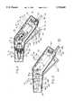
- FIG. 1is a pictorial view of a handpiece embodying the invention.
- FIG. 2is a laterally exploded pictorial view of the FIG. 1 handpiece.
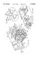
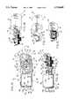
- FIG. 3is an enlarged elevational view of the FIG. 1 handpiece with the leftward housing part removed.
- FIG. 4is a view similar to FIG. 3 but with the suction hose removed, the left drive unit shell part removed and the drive unit exposed in central cross-section, such that FIG. 4 approximates a central cross-sectional view of the FIG. 1 handpiece.
- FIG. 4Ais an enlarged fragment of FIG. 4 detailing the rearward portion of the handle.
- FIG. 4Bis an enlarged fragmentary pictorial view, taken from the front, of the electrical contact support posts seen in FIG. 4A.
- FIG. 4Cis an enlarged fragmentary exploded pictorial view of the electrical contacts, associated with the FIG. 4B posts and associated electrical conductors from the battery supply.
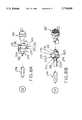
- FIG. 5is an enlarged, exploded, pictorial view of the drive unit of FIG. 2.
- FIG. 6is a sectional view substantially taken on the line 6--6 of FIG. 5, and provides a top view of the bottom drive unit shell part of FIG. 5 (the rightward one of FIG. 2) with the drive components removed to show the interior configuration of that shell part.
- FIG. 7is a sectional view substantially taken on the line 7--7 of FIG. 5, and provides a view similar to FIG. 6 but showing the interior configuration of the other drive unit shell part (the upper one in FIG. 5 and leftward one in FIG. 2).
- FIG. 8is an enlarged central cross-sectional view of a tip unit usable with the handpiece of FIG. 2 and showing same installed in a pump unit shown in central cross-section substantially as in FIG. 4.
- FIG. 8Ais a reduced size, fragmentary, side elevational view of the apparatus of FIG. 8.
- FIG. 8Bis a pictorial view of the apparatus of FIG. 8A.
- FIG. 9is an end elevational view of the drive unit, taken from the right end in FIGS. 2 and 3.
- FIG. 10is a sectional view substantially taken on the line 10--10 of FIG. 5 and showing the drive unit with one shell part (the left one in FIG. 2 and top one in FIG. 5) removed to show the motor and transmission.
- FIG. 11is an elevational view of the drive train substantially taken on the line 11--11 of FIG. 10.
- FIG. 12is a central cross-sectional view substantially taken on the line 12--12 of FIG. 10.
- FIG. 13is a fragmentary cross-sectional view substantially taken on the line 13--13 of FIG. 10.
- FIG. 14is a cross-sectional view substantially taken on the line 14--14 of FIG. 10.
- FIG. 15is a sectional view substantially taken on the line 15--15 of FIG. 10.
- FIG. 16is an exploded pictorial view of the pump unit of FIG. 2 in an enlarged scale.
- FIG. 17is a front end elevational view of the pump unit of FIG. 16 taken substantially from the left side of FIGS. 2-4 and 16.
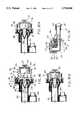
- FIG. 18is a central cross-sectional view of the pump unit of FIG. 17 taken substantially on the line 18--18 of FIG. 17.
- FIG. 18Ais a fragment of FIG. 18 showing the pump unit at the beginning of an intake stroke.
- FIG. 18Bis a fragment of FIG. 18 showing the pump nearing the end of an output pulse.
- FIG. 18Cis a fragmentary enlargement of FIG. 18 showing the valve member.
- FIG. 19is a fragmentary cross-sectional view showing the connection of the pump unit to the liquid supply hose.
- FIG. 20is a pictorial view of the electric power supply unit connected to the FIG. 2 handpiece.
- FIG. 21is a left end view of the FIG. 20 electric power supply unit.
- FIG. 22is an exploded pictorial view of the electric power supply unit of FIG. 20.
- FIG. 22Ais an electrical schematic of the FIG. 2 handpiece and FIG. 20 electric power supply unit.
- FIG. 23is a central cross-sectional view taken substantially on the line 23--23 of FIG. 22.
- FIG. 23Ais an enlarged fragmentary pictorial view of the support structure for battery contacts at the forward (left in FIG. 23) end of the electric power supply casing.
- FIG. 23Bis an enlarged pictorial view similar to FIG. 23A but showing the support structure for battery contacts at the rearward (rightward in FIG. 23) end of the power supply casing.
- FIG. 24is a sectional view substantially taken on the line 24--24 of FIG. 22 and showing the electric power supply unit with its top cover removed.
- FIG. 25is a sectional view substantially taken on the line 25--25 of FIG. 22 and showing the underside of the cover of the power supply casing.
- FIGS. 26, 27 and 28are enlarged pictorial views of battery contacts of FIG. 22.
- FIG. 29is an enlarged fragmentary pictorial view of an embodiment of the liquid supply and electric wiring harness of the apparatus of FIGS. 2 and 20 but showing a modification in the attachment of the electrical and liquid handling components.
- a pulsed irrigation handpiece 10embodying the invention comprises a hand-held housing 11 having a handle 12 and a barrel 13 which extends forward from the upper end of the handle 12 at about a 130° to 150° (here about 145°) angle thereto.
- the housing 11is hollow and, for convenience in assembling the handpiece 10, is constructed as laterally opposed concave left and right housing parts 14 and 15 (FIG. 2).
- the housing parts 14 and 15are preferably molded rigid plastic elements held together rigidly by any convenient means, here comprising undercut snap fit tabs 16 protruding from the top and bottom edges of the right housing part 15 to snap over an interior edge flange (not shown) on the top and bottom edge of the left housing part 14.
- any convenient meanshere comprising undercut snap fit tabs 16 protruding from the top and bottom edges of the right housing part 15 to snap over an interior edge flange (not shown) on the top and bottom edge of the left housing part 14.
- precise registry together of the two housing partscan be assisted by laterally projecting pins 20 distributed along the edges of one housing part (here the left housing part 14) piloted in holes 21 (FIG. 4) in the opposed edges of the other housing part (here 15).
- the two housing parts 14 and 15may be adhesively bonded together.
- the drive unit 25(FIGS. 2-15) is self contained in its own shell 26 (FIG. 2).
- the shell 26comprises two opposed concave shell parts 30 and 31 respectively disposed to the left and right in FIG. 2.
- the shell parts 30 and 31are preferably of rigid molded plastics material.
- the shell parts 30 and 31are held fixedly together by any convenient means, here by resilient snap connection of generally U-shaped clips 32, molded in spaced relation along the perimeter edge of the shell part 31 which overlap the perimeter edge of the shell part 30 and snap over tabs 33 protruding therefrom, as seen in FIGS. 5-7.
- Precise location of the shell parts 30 and 31 with respect to each otheris assisted by locator pins 34 fixedly protruding from the shell part 31 and holes 35 in the opposed portions of the shell part 30.
- a conventional DC energizable electric motor 36(FIGS. 4 and 5) is snugly housed in the space between the left and right (FIG. 2) shell parts 30 and 31 at the rear (left in FIGS. 5-7, 10 and 12) thereof.
- the motor 36is snugly axially located between the rear end wall 40 and a transverse internal bulkhead 41 of the shell 26 (FIGS. 5-7, 10 and 12).
- the rear end wall 40 and bulkhead 41have opposed parts in the left and right shell parts 30 and 31, as seen in FIGS. 6 and 7.
- Rear and front bosses 42 and 43respectively extend rearward and forward from the cylindrical casing 44 of the motor 36, as seen in FIGS. 10 and 12, and are supported in corresponding coaxial recesses 45 and 46 in the rear end wall 40 and bulkhead 41 respectively, so as to support the motor casing 44 with respect to the shell 26.
- a flat 47 on the rear boss 42(FIG. 9) co-acts with a corresponding flat in the surrounding recess 45 to prevent rotation of the motor casing 44 with respect to the shell parts 30 and 31, such that the motor 36 is antirotationally fixed within the shell 26.
- the drive unit 25further includes a transmission 50 (FIG. 5) coaxial with and forward of the motor 36.
- the transmissionincludes a reciprocating link member 51 and is driven from the forward extending, rotating output shaft 52 of the motor 36.
- the shaft 52extends coaxially forward through the front boss 43 (FIG. 12) of the motor 36.
- the transmission 50(FIGS. 5 and 12) includes a pinion gear 53 fixed on the motor shaft 52 for rotation thereby, and a face gear 54 which, as seen in FIG. 12, underlies the pinion gear 53.
- the face gear 54has a relatively large diameter central disk 56 carrying upward facing teeth 55 engaging corresponding teeth on the pinion gear 53 for rotation thereby.
- the face gear 54includes a secondary pinion gear 57 fixed coaxially beneath the disk 56, and of substantially lesser diameter, which in turn drives a relatively large diameter output gear 60.
- the pinion gear 53, face gear 54, secondary pinion 57 and output gear 60are all provided with a full circumferential (360°) set of teeth, so that continuous rotation of the motor shaft 52 results in continuous rotation of the output gear 60.
- some or all the gear teethare not shown in various of the drawings, the toothed meshing connection of the gears therein thus being only schematically shown. See for example FIGS. 4, 10, 12, 13 and 14.
- An output shaft 61is fixed to and coaxially upstanding from the output gear 60 (FIG. 12) and fixedly rotatably drives an eccentric member 62 (FIGS. 5, 10 and 12) spaced above the output gear 60.
- the output shaftis of rectangular cross-section to maximize its torque transmitting capability.
- the eccentric member 62comprises a radially extending disk 63 (FIG. 5) coaxial with the output shaft 61 and fixedly surmounted by an eccentric circular cylinder 64 eccentrically rotatable with the output shaft 61.
- the link member 51is generally T-shaped, as seen in FIG. 13, having a plate-like body 70 overlying the disk 63 of the eccentric member 62 and lying at right angles to the output shaft 61, and further having a plate-like fork 71 fixed at the rightward (FIGS. 5, 10, 12 and 13) end of the plate- like body 70 and extending in a plane substantially parallel to the output shaft 61.
- the plane of the plate-like fork 71is perpendicular to the intended direction of reciprocating movement of the link member 51.
- the body 70at its end portion remote from the fork 71, has an oblong through opening 72 snugly radially receiving the rotating eccentric cylinder 64 of the eccentric member 62, as seen in FIG. 10.
- the length direction of the oblong opening 72extends parallel to the plane of the fork 71 and is of sufficient length to accommodate 360° rotation of the eccentric cylinder 64 without movement of the body 70 parallel to the plane of the fork 71.
- the width of the oblong opening 72namely in a direction perpendicular to the plane of the fork 71, corresponds substantially to the diameter of the eccentric cylinder 64, providing a sliding clearance between the body 70 and eccentric cylinder 64, so that rotation of the eccentric cylinder 64 will result in reciprocation of the link member 51 in a direction perpendicular to the plane of the fork 71.
- the plate-like body 70includes a thickened rim 73 (FIG. 5) around the oblong opening 72 and may thus be said to form a yoke for coaction with the eccentric cylinder 64.
- the side edges of the body 70are preferably also thickened to form parallel longitudinal guide rails 74 (FIG. 10).
- the above discussed moving elements of the transmission 50are located and movably supported within the shell 26 as follows.
- the face gear 54has coaxial downward and upward (FIGS. 5-7, 10 and 12) extending stub shafts 75 and 76 respectively rotatably supported in coaxial bearing bosses 80 and 81 respectively fixed on the opposing faces of the shell parts 31 and 30 (FIGS. 6, 7 and 12).
- the output gear 60 and the eccentric member 62have respective downward and upward extending stub shafts 82 and 83 coaxial with the output shaft 61 and rotatably supported in respective cylindrical bearing bosses 84 and 85 in the respective shells 31 and 30 (FIGS. 5-7 and 12).
- the link member 51is slidably guided for reciprocation in a notch 90 (FIGS.
- the notch 90has parallel opposed guide faces 92 (FIG. 7) spaced apart to snugly slidably guide therebetween the opposite guide rails 74 of the link member 51, and thus spaced at substantially at the maximum width of the link member.
- the thickness of the link memberis guided for reciprocation between the peripheral edge 93 of the right (lower in FIG. 5) shell 31 and the width wall 94 (FIGS. 5 and 7) of the other shell part 30.
- the central length axis LA (FIG. 10) of the link memberintersects the central length axis MA of the motor shaft 52 at the axis SA of the output shaft 61 and stub shaft 83 (FIGS. 10 and 12), at an angle equal to the angle between the central length axis of the handle 12 and barrel 13 of the housing 11.
- the length axes of the handle and barrelalso intersect at the axis SA of the output shaft 61 when the drive unit 25 is installed in the handpiece housing 11 as hereafter discussed.
- the link member longitudinal axis LA and motor shaft axis MAdefine the length axis of the barrel 13 and handle 12, respectively, when the drive unit 25 is installed in the handpiece housing 11.
- the drive unit 25is located within the handle 12, as follows. As seen in FIGS. 3 and 4, transverse ribs 95 are molded into the interior surface of the handle 12 at opposing locations in the left and right housing parts 14 and 15 (FIGS. 2-4). For drawing convenience, only the ribs in the right housing part 15 are shown, the ribs in the left housing part 14 being compatible.
- the ribs 95locate the drive unit 25 in the rightward/leftward direction in FIG. 2.
- the drive unit shell bosses 84 and 85protrude sideways from the drive unit shell and are pivotally received in corresponding hollow cylindrical bosses, one of which is shown at 96 in FIG. 2, and which extend toward each other from the interior of the left and right housing parts 14 and 15.
- the hollow cylindrical boss 96 of the left housing part 14is not shown but is opposed to and compatible with the housing part 96 shown in the right housing part 15 of FIG. 2.
- the drive unit 25is thus, except for the lateral positioning defined by the ribs 95, pivotally located within the handpiece housing 11 and is thus capable of some pivotal floating in the housing to achieve proper alignment of the longitudinal movement axis LA (FIGS. 7) of the link member 51 with respect to the barrel 13 and a pump unit 100 (FIGS. 2-4 and 16-18) located in the barrel 13 as hereafter discussed.
- the pump unit 100includes a bellows 101 including an axially expandable and contractible flexible bellows wall 114 (FIG. 18) and a forwardly extending, rigid, annular flange wall 102.
- a flange wall 102is loosely telescoped over a rigid rearwardly extending annular flange 103 of a rigid, forwardly extending coaxial bellows housing 104.
- the bellows 101 and bellows housing 104are preferably of molded plastics material.
- a resilient O-ring 105(FIGS. 16 and 19) is snugly radially disposed between the radially opposed, axially extending annular flanges 102 and 103, to create a fluid seal therebetween and hence between the bellows 101 and bellows housing 104, to prevent fluid leakage therebetween.
- the bellows 101 and bellows housing 104have respective axially spaced radially extending steps 106 and 107 joined to the respective annular flanges 102 and 103 and axially spaced apart at a distance substantially greater than the diameter of the O-ring 105, as seen in FIG. 19.
- the axial extending flanges 102 and 103 and radially extending steps 105 and 106define an annular chamber 110 in which the O-ring 105 is axially loosely, and radially snugly and sealingly, disposed.
- the radially opposed surfaces of the axially extending annular flanges 102 and 103are cylindrical, such that neither has an annular groove in which the O-ring seats.
- the O-ringis free to roll on the radially opposed cylindrical surfaces of the axially extending flanges 102 and 103 and the O-ring 105 does not significantly interfere with axial separation of the bellows 101 and bellows housing 104 from each other.
- ribs 111are also schematically indicated in FIG. 18.
- the rear (right in FIG. 19) end of the bellows housing axial flange 103abuts the radially extending step 106 of the bellows 101 and the forward (leftward in FIG. 19) end of the bellows axial flange 102 axially abuts a radial flange 112 which extends radially outward from and forwardly from the bellows housing step 107.
- the forward end of the bellows axial flange 102thus radially overlaps the bellows housing step 107 in snug but axially slidable relation thereto.
- a small forwardly extending annular rib 113protrudes forwardly from the bellows radial step 106 toward the O-ring 105 to prevent rearward escape of the O-ring 105 from the space between the axially extending flanges 102 and 103, in the event of slight axial shifting of the bellows 101 and bellows housing 104 away from each other.
- the above-mentioned bellows wall 114extends rearward from the inner periphery of the radially extending annular step 106 of the bellows 101 (FIG. 18) and consists of an axially collapsible and extensible, flexible, wave cross- section, peripheral wall 114.
- the bellows wall 114surrounds an axially expansible and contractible pumping chamber 115.
- a radially extending drive end wall 116closes the rear end of the bellows wall 114 and pumping chamber 115.
- a stub 120having a radially enlarged head 121, is fixed to and extends coaxially rearwardly from the drive end wall 116.
- the above discussed link member 51 (FIG. 5) of the drive unit 25has its fork 71 provided with a central, radially opening, generally U-shaped slot 122 (FIGS. 11-13).
- the slot 122divides the fork 71 into a pair of tines 123 (FIG. 11).
- the slot 122opens leftwardly in FIG. 2, namely away from the rightward housing part 15 and toward the leftward housing part 14.
- the central portion 124 (FIG. 11) of the slot 122is undercut by inward tapering of an intermediate portion 125 of the slot 122 as seen in FIG. 11.
- the tapered portion 125 of the slot 122 (FIG. 11)defines a snap fit detente for resiliently trapping the bellows stub 120 in the drive unit slot 122.
- the bellows stub 120To install the bellows stub 120 in the slot 122, the bellows stub 120 must be resiliently forced through the tapered portion 125 of the slot 122 and upon passing the latter, the stub resiliently snaps into the central portion 124 of the slot.
- the inner ends of the tapered portion 125 of the slotresiliently maintain the stub radially inboard thereof, in the central portion 124 of the slot 122.
- the stub 120 and hence the bellows 101, and indeed the entire pump unit 100,is thus freely rotatable about its length axis with respect to the fork 71, so that the circumferential orientation of the drive unit 25 and the pump unit 100 is determined by the location thereof in the housing.
- the drive unit 25 and pump unit 100are thus, to an extent, free to circumferentially float with respect to each other, about the connection of the stub 120 and fork 71, without interfering with the circumferential location of the drive unit 25 and pump unit 100 in the housing 11.
- edges of the slot 122in particular of the central portion 124 thereof, are rounded in cross-section, as is the stub 120, to permit a modest amount of angular adjustment between the length axes MA and LA of the drive unit 25 and pump unit 100 and to allow the drive unit 25 and pump unit 100 to easily settle into their proper operating positions in the housing 11.
- a cylindrical plug 126is coaxially fixed to the interior side (left side in FIG. 18) of the bellows drive end wall 116 by a coaxial, rearward extending, undercut pin 127 snap fitted in a forwardly (leftwardly in FIG. 18) opening recess in the stub 120.
- the plug 126has a diametral slot 130 opening forward from its front end and which faces forward toward a resilient valve member 131 (FIGS. 16 and 18) to maintain liquid communication between the central and radially outer portions of the pumping chamber 115.
- the bellows 101is thus a single element which carries out four different functions, namely sealing at the forward end, changing the pump chamber size in the middle thereof, the rearend acts as a piston and as a drive point.
- the front annular flange 102helps locate the pump unit with respect to the housing barrel.
- the pump unit 100further includes a valve member 131, which is a one piece member of suitable resilient material and which by itself constitutes the entire moveable inlet and outlet valve system for the pump unit 100. More particularly, the valve member 131 comprises a short tubular central portion 132 (FIG. 18) which coaxially connects a forward (leftward in FIG. 18) tapering, duck bill type, outlet valve 133 and a rearwardly and radially outwardly extending umbrella type, inlet valve 134.
- the umbrella valve 134is annular and has a central opening 135 which communicates coaxially from the pumping chamber 115 in the bellows 101 forwardly through the tubular central portion 132 and outlet duck bill valve 133 of the valve member 131.
- the bellows housing 104comprises a rear (right in FIGS. 18 and 18C) facing recess having a perimeter defined by the annular flange 103 of the bellows housing 104 and a rear facing radial wall 136 which defines the front end of the pumping chamber 115.
- the umbrella valve 134lies coaxially in the resulting recess 103, 136.
- the forward facing perimeter 137 of the umbrella valve 134in its closed condition shown in FIGS. 18 and 18C, presses forward against the radial wall 136 to seal thereagainst.
- the valve member 131is held against the right (rearward) movement away from the bellows housing wall 136 by axial interference between a rightward facing, radially outward extending, annular step 140 (FIG. 18C) at the rear (right) end of the duck bill valve 133, and a radially inward extending, leftward facing, annular flange 141 of the bellows housing 104.
- the radially inward directed, annular flange 141is axially interposed between, and forms a port 142 between, the rear facing recess 103, 136 and a coaxial, forwardly extending, cylindrical, irrigation liquid outlet conduit 143 (FIGS. 18 and 18C).
- the tubular central portion 132 of the valve member 131extends snugly axially through the port 142.
- valve member 131To install the valve member 131 in the bellows housing 104, the tapered outlet duck bill valve 133 is pushed forward through the port 142, the bellows valve step 140 snaps forwardly (leftwardly in FIG. 18C) past the bellows housing flange 141, and the sealing perimeter 137 of the umbrella valve 134 is thereby pulled forwardly resiliently against the rearward facing bellows housing wall 136, leaving the valve member 131 with its duck bill valve 133 and umbrella valve 134 both in their closed condition shown in FIGS. 18 and 18C.
- the bellows housing 104further includes an annular liquid jacket 144 (FIGS. 18 and 18C) surrounding the rear portion of the liquid outlet conduit 143 and defining radially therebetween an annular liquid inlet chamber 145 (FIGS. 18, 18C and 19).
- the inlet chamber 145communicates between a radial inlet port 146 (FIGS. 16 and 19), which opens radially outward through the side of the bellows housing 104, and an annular space 147 (FIG. 18C).
- the annular space 147is bounded by the forward face 150 and tubular central portion 132 and sealing perimeter 137 of the umbrella valve 134 and the radial face 136 of the recess 103, 136 of the bellows housing 104.
- a rightward pullback of the bellows head 121axially expands the bellows, from its FIG. 18A position towards its FIG. 18 position. This reduces the pressure within the bellows. This in turn keeps the duck bill valve 133 closed and pulls the sealing perimeter 137 of the umbrella valve 134 rightwardly away from the bellows housing recess radial wall 136 and draws liquid from the port 146 through the annular inlet chamber 145, around the perimeter 137 of the open umbrella valve and into the interior of bellows.
- a leftward push forward of the bellows head 121axially compresses the bellows from its FIG. 18 position toward its FIG. 18B position and raises the pressure in the bellows, to close the umbrella valve 134 and open the duck bill valve 133 and force a pulse of liquid out of the bellows forwardly through the duck bill valve 133 and liquid outlet conduit 143.
- Irrigation liquidis drawn to the inlet port 146 of the bellows housing 104 through an elbow 151 (FIG. 19).
- the outlet end 152 of the elbow and the inlet port 146are cylindrical, with the elbow outlet end 152 being a snug axially sliding fit in the inlet port 146.
- An axially elongate, annular groove 153 in the outer periphery of the elbow outlet 152houses a seal ring, here an O-ring, 154 which bears sealing and rollingly on the radially opposed and surrounding surface of the inlet port 146 to prevent liquid leakage out of the elbow 151 at its interface with the inlet port 146.
- the elbow 151is not mechanically interlocked with the inlet port 146 but can slide in and out with respect thereto.
- the elbow 151is held in place with its outlet end 152 sealingly within the port 146 by bearing of a portion 155 (FIG. 4) of the handpiece housing barrel 13 against the outboard surface 156 of the elbow 151, with the pump unit installed in the handpiece housing 11.
- the elbow 151here fixedly carries a pair of parallel fins 157 (FIGS. 16, 17 and 19).
- the fins 157extend radially from the rear inlet end portion of the elbow 151 and axially sandwich therebetween the flanges 106 and 112 of the bellows 101 and bellows housing 104, at least to help the housing ribs 111 (FIG. 18) fins 157 prevent axial separation of the bellows and bellows housing.
- the housing ribs 111 and fins 157are more or less evenly circumferentially located around the bellows 101 and bellows housing 104.
- An elongate flexible irrigation liquid supply hose 160(FIGS. 2, 4, 16, 17, 19, 22, 23, 25 and 29) has a forward end 161 which telescopes sealing and fixedly over the rear end 162 of the elbow 151 as seen in FIGS. 19 and 29. Although an annular barb is shown at 162 (for example in FIG. 19) a barbless, cylindrical end 162 is satisfactory.
- the irrigation liquid hose 160extends rearward from the elbow 151 (FIG. 4) in the barrel 13 of the housing and angles downwardly and rearwardly along the bottom of the handpiece handle 12 to exit rearwardly and downwardly through a hole 163 (FIG. 2) in the bottom end wall 164 of the handpiece housing 11.
- a clamp plate 165(FIGS.
- a notch 167in the rightward end of the clamp plate 165 permits exit therethrough of irrigation liquid supply hose 160 from the handpiece housing 11 and snugly and frictionally grips such hose, without crushing or collapsing it, so that such hose 160 cannot easily be pulled out of the housing 11 or off the elbow 151.
- the irrigation liquid hose 160has fixed on the outside thereof, as by extruding or molding integrally therewith, a smaller diameter rib 170 (FIGS. 2, 16 and 17).
- a plurality (here three) of insulated electrical conductors (wires) 171have intermediate portions contained within and extending the length of the rib 170. Forward end portions of the insulated wires 171 emerge from the forward end of the rib 170 and carry conventional electrically conductive connectors 175.
- the forward end of the rib 170extends through the notch 167 (FIG. 2) and ends just inside the bottom portion of the handle 12 of the housing 11, as seen in FIG. 4.
- the forward ends of the conductors 171, carrying the connectors 175,extend into the lower portion of the handpiece handle 12 for purposes appearing hereinafter.
- the insulated electrical conductors 171extend along the length of the central portion of the liquid supply hose 160 and have rear ends provided with respective electrically conductive connectors 176 (FIGS. 22 and 29), such that electric current can flow from a given rear connector 176 through its corresponding insulated electrical conductor 171 and to its corresponding front electrically conductive connector 175 in a conventional manner. Short rear portions of the conductors 171 are loose and moveable with respect to the liquid supply hose 160 as seen in FIGS. 22 and 29.
- the electrical connectors 175 and 176are conventional crimp type connectors.
- the elongate central portion of the insulated electrical conductors 171may be fixed side by side, in a flat array, to the outside of the liquid hose 160, as shown in FIGS. 22 and 29, and such can be accomplished by adhesive bonding or by any other convenient means.
- the hose 160, 170thus serves the dual use of conveying both irrigation liquid and electric operating power.
- the rear end 177 (FIGS. 22 and 23) of the liquid hoseis here provided with a fitting 180 of hollow tubular construction open to axial liquid flow therethrough.
- the fitting 180comprises a forward end portion 181 (FIG. 23) fixed sealingly telescoped in the rear end 177 of the liquid hose 160, a square central flange 182 (FIG. 22) and a rear end portion (or "spike") 183 having a sharpened tip 184.
- the tip 184is capable of conventional insertion into a conventional source S (FIG.
- irrigation liquidfor example a conventional supply bag, for conveying irrigation liquid therefrom forward into the hose 160.
- the square flange 182prevents rotation of the fitting 180 in the casing 191, which helps when removing the spike 183 from the liquid supply bag.
- the rear end portion 183is covered by a protective cap 185 prior to use so that the sharpened tip 184 will not accidentally be dulled.
- the length of the liquid supply hose 160allows the irrigation liquid source S to be located at a distance from the handpiece and thus out of the way of the surgical personnel at the operating table where the handpiece 10 is to be used.
- a compact, self contained electrical power supply unit 190(FIGS. 20-25) is fixed on the rear end portion 177 of the liquid hose 160, and is thus located remotely from the handpiece 10, adjacent to the source S of irrigation liquid.
- the power supply unit 190comprises a casing 191 preferably of rigid molded plastics material.
- the casing 191here comprises a relatively deep, substantially rectangular pan 192 (FIG. 2) whose top (as oriented in FIGS. 22 and 23) is fixedly closed by a cover 193.
- the pan 192has front and rear end walls 194 and 195 (FIGS. 23, 23A and 24) having fixed upward opening slots 200 each defined by a laterally spaced, opposed pair of U-shaped flanges 201 (FIGS. 23A and 23B).
- the slots 200are undercut in that each has a mouth 202 laterally narrower than the remainder of the slot 200 and communicating between the remainder of the slot 200 and the interior cavity of the pan 192.
- the undercut slots 200are of constant cross-sectional size and shape vertically (i.e. into and out of the page in FIG. 24 and up and down in FIG. 23).
- the reference numerals 200 and 201are suffixed, so that the undercut slots and U-shaped flanges on the front pan wall 194 are indicated by the reference characters 200F and 201F and the undercut slots and U-shaped flanges on the rear pan wall 195 are indicated at 200R and 201R.
- the U-shaped flanges 201F defining the slots 200F on the forward end wall 194start substantially from the pan bottom wall 196 and extend a bit less than half way up the front end wall 194.
- the U-shaped flanges 201R of the slots 200R on the rearward end wall 195 of the panare spaced above the bottom wall 196 of the pan upon respective block-like pillars 203 which define an upfacing bottom 204 for each of the U-shaped flanges 201R on the rear pan wall 195.
- a central block 205Rising from bottom wall 196 of the pan between the two central pillars 203 to a height below the bottoms 204 of the slots 200R thereof, is a central block 205 from which forwardly extends, along the pan bottom wall 196, a T-shaped flange 206 (FIG. 23B) of constant cross section vertically and defining a pair of vertically open and laterally oppositely opening grooves 207 disposed immediately forward from the two central pillars 203 on the rear pan wall 195.
- Two such undercut slots 200Fare spaced symmetrically side by side on the front pan wall 194. Similarly, and at the same effective lateral spacing, two such slots 200R are spaced laterally side by side on the pan rear wall 195.
- Springy, electrically conductive sheet metal battery contacts of three different kindsare indicated at 210 and 211 and 212 and FIGS. 26, 27 and 28 respectively.
- a pair of such contacts 210are provided and each comprises a generally rectangular foot 213 adapted to snugly slide down into a respective undercut slot 200F at the pan front wall 194.
- Each foot 213is provided with resilient toes 214 angled out of the plane of the foot 213 and adapted to bite against the interior of the corresponding undercut slot 200F to fix the corresponding battery contact 210 in place therein.
- each of a pair of battery contacts 212has a resilient fork-shaped foot 215 adapted to fit snugly and slidingly down into the corresponding undercut groove 200R at the rear wall 195 of the pan 192 and with springy toes 216 for fixedly gripping the interior of the corresponding undercut slot 200R.
- the single, low speed battery contact 211(FIG. 27) has a resilient U-shaped foot 217 for sliding down over the T-shaped flange 206 (FIG. 23B), with springy toes 218 bent out of the plane of the foot 217 for bitingly engaging the walls of the grooves 207 of the T-shaped flange 206.
- Each of the battery contacts 210, 211 and 212thus slides with its corresponding foot into the desired location with respect to the grooves 200F, 200R and 207 and locks fixedly therein. This is generally indicated in FIGS. 22-24.
- the battery contacts 210, 211 and 212have respective resilient fingers 221, 222 and 223 (FIGS. 26, 27 and 28 respectively), two each for the battery contacts 210 and 211 and one each for the battery contacts 212.
- Such fingers 221, 222 and 223protrude from the respective slots 200F, 200R and 207 into the interior of the pan 192 for electrically contacting batteries 230 (FIG. 22) to be housed in the pan 192.
- the battery contact 211 and each of the battery contacts 212(FIGS. 27 and 28 respectively) have an upstanding terminal (224 and 225 respectively) of simple rectangular shape for releasable telescoped engagement within a respective one of the connectors 176 at the rear ends of the three insulated electrical conductors 171 (FIG. 22).
- one embodiment according to the inventionadvantageously uses batteries of a kind widely available in retail stores, namely AA size alkaline batteries.
- these batteriesadvantageously are inexpensive, have a long shelf life and provide full operating voltage until almost fully discharged.
- eight such batteries 230are provided and are individually indicated at B1, B2, B3, B4, B5, B6, B7 and B8.
- ribs 231 extending circumferentially within the pan 192cradle the batteries 230 fixedly but removably within the pan 192.
- the polarity of the eight batteriesis indicated by "plus" signs marked thereon.
- the batteries 230are arranged in four rows of two head-to-tail batteries each. Four of the batteries 230 lie in the bottom (FIGS. 22 and 23) of the pan in two rows of two each and the remaining four batteries 230 lie on top of those.
- the ends of the battery rowsbear variously on the above discussed battery contacts 210, 211 and 212 as generally indicated for example in FIG. 22 and also in the schematic circuit drawing in FIG. 22A. More particularly, the four batteries B1, B2, B3 and B4 defining a vertical plane nearest to the viewer in FIG. 23 are connected in series from the near connector 212 leftwardly through the top row of batteries, down through the near upstanding connector 210 and thence rightwardly through the bottom pair of batteries to the lower rear connector 211. The remaining four batteries B5-B8 are arranged in a vertical plane behind above-mentioned batteries B1-B4. More particularly, the batteries B5-B8 connect in series from the far side of the lower rear connector 211 forwardly (leftwardly in FIG. 22) to the far connector 210, upwardly therethrough, and then rearwardly back to the far upper connector 212.
- the cover 193(FIGS. 23 and 25) has plural, laterally extending, depending ribs 232 (FIGS. 23 and 25) intended to seat upon the uppermost batteries B1, B2, B7 and B8 and fix the batteries B1-B8 in the pan with the cover 193 fixed in its normal closed position atop the pan 192.
- the coveris fixedly securable atop the pan by any convenient means, such as snap fit connectors, a portion of which are generally shown in 233 in FIG. 22, and generally like those discussed above with respect to the handpiece housing 11, as at 16, and as generally discussed with respect to the drive unit shell 26, as at 32, 33.
- the aforementioned rear end 177 of the hose 160extends through the casing 191 along the horizontal parting plane between the pan 192 and cover 193, and so lies close adjacent the topmost batteries B1, B2, B7 and B8.
- Hollow front and rear bosses 234 and 235extend forward and rearward respectively, from the casing 191. At the parting plane between the pan 192 and cover 193, the bosses 234 and 235 are notched (for example at 236 in FIG. 22) for extension therethrough of the rear end 177 of the liquid hose 160.
- the rear hollow boss 235is sized and shaped to receive radially therein the square flange 182 (FIG. 23) on the rear end of the liquid hose 160, and thereby axially fix the rear end of the liquid supply hose 160 within the casing 191 and nonrotatably fix the fitting 180 to the battery casing 191.
- the notch 236 in the front boss portion 234 on the cover 193is indented by one or more small recesses 237 for receiving axially therethrough the rib 170 containing the insulated electrical conductors 171, whose rear end connectors 176 are respectively fixed to the terminals 224 and 225 of the battery contacts 211 and 212.
- the handpiece 10further includes a trigger unit 240 (FIGS. 2-4) for controlling actuation of the motor 36.
- the trigger unit 240comprises a generally L-shaped trigger member 241 (FIGS. 2, 4 and 4A) comprising an elongate trigger lever 242.
- the upper, forward (leftward in FIGS. 2 and 4) end of the trigger leveris pivoted by laterally extending integral pins 243 pivotally receivable in suitable holes in laterally opposed bosses 244 (one of which is shown in FIG. 2) in the opposing lower edges of the housing parts 14 and 15, near the rear end of the barrel 13. Snapping together of the two housing parts 14 and 15 thus captures the pivot pins 243 and pivotally mounts the trigger with respect to the handpiece housing 11.
- the trigger lever 242includes a transverse ridge 245 (FIG. 4) near to but spaced rearwardly from the pivot pins 243 and facing the underside of the barrel 13 and adapted to bear on the underside thereof in the manner of a fulcrum.
- This rearward trigger part 246is relatively rigid in the portion thereof spaced at least somewhat to the rear of the fulcrum ridge 245.
- Such rigidityis assisted by a forward facing longitudinal reinforcement rib 247 extending rearward along the front face of the trigger lever 242 from a point near the fulcrum ridge 245.
- the front of the trigger lever 242, to the rear of the fulcrum ridge 245is, in the embodiment shown, provided with transversely extending ribs 248 to provide the user with a non-slip grip of the trigger lever 242.
- the trigger lever 242is bendable near the fulcrum ridge 245, both to the front and rear thereof, in a resilient manner. In this way, the resilience of the trigger lever tends to hold it in its forward, inactive position shown in FIG. 4, with the fulcrum ridge 245 bearing on the underside of the handpiece barrel 13.
- the trigger leverbends in the region of the fulcrum ridge 245, tending to straighten from its relaxed convexly forwardly curved configuration of FIG. 4, so that the rear face of the trigger lever can be pulled into the dotted line position 242P, substantially against the front face of the handle 12.
- the natural resilience of the trigger lever 242unbends it back to its solid line forward position shown in FIG. 4. Accordingly, the trigger naturally returns forward to its non-operative position without need for a separate return spring.
- the trigger arm 251fixedly carries a thumb 250 (FIG. 4A) intermediate it ends in the housing handle 15 and which interferes with the housing wall adjacent the hole 252, to prevent the resilient restoring force of the trigger lever 242 from pulling the trigger arm 251 leftwardly (FIG. 4A) out of the housing handle 12.
- a plank-like switch contact support arm 251protrudes substantially at a right angle from the rear, or bottom, end of the trigger lever 242 and extends upwardly and rearwardly (in FIG. 4) into the lower portion of the handle 12, loosely through a hole 252 (FIG. 4A) in the opposing bottom wall of the handle.
- a plate-like electrically conductive contact blade 253fixedly extends through the thickness of the arm 251, and has a front portion exposed towards said motor and a rear portion exposed toward the bottom end 164 of the handpiece handle.
- a pair of rectangular posts 255 and 256protrude fixedly into the interior of the handle 12 from the inside of the right housing part 15, about midway between the drive unit 25 and the housing bottom end 164 (FIGS. 4A and 4B).
- Each post 255 and 256includes a T-shaped flange 260 extending substantially forward toward the drive unit 25.
- Each T-shaped flange 260defines a pair of oppositely facing grooves 261 (FIG. 4C).
- Electrically conductive, spring-like metal contacts 262 and 263each have a substantially U-shaped foot 264 for reception on the T-shaped flange 260 of the corresponding posts 255 and 256.
- the contacts 262 and 263further each have a substantially rectangular, projecting terminal 265 for telescopic fixing thereon, in electrically connected relation, a corresponding one of the front connectors 175 of the three insulated electrical conductors 171.
- the electrical contacts 262 and 263further have respective, generally L-shaped, plate-like, flexible contact leaves 266 and 267 (FIG. 4C). The contact leaves 266 and 267 extend toward the drive unit 25 as seen in FIG. 4A.
- the contact 271is a conventional terminal (like those at 224, 225 and 265) for receiving one of the front connectors 175 in fixed and electrically conductive relation thereon.
- the contact 270is an elongate, springy rectangular piece, bent intermediate its ends in dogleg fashion, and angling from the rear end of the motor 36 rearwardly and somewhat rightwardly (in FIG. 4A) to a free end portion spaced near the contact leaves 266 and 267.
- the free (rightward in FIG. 4A) end of the arm 251is beveled at 272 to help it ride over the contacts 266 and 267 as the trigger lever 242 is sequentially squeezed more and more toward the handle 12.
- the arm 251is progressively resiliently bent, like a leafspring, as its free end rides over the fixed contacts 266 and 267, to firmly press its contact blade 253 against the latter.
- the beveled free end of the arm 251rides over the contact leaf 266 past its dotted line position 253A and toward its dotted line position 253B.
- the contact blade 253slides into electrical contact with the contact leaf 266 and the motor contact 270 to establish electrical connection therebetween.
- the motor contact 270resiliently bends to allow continued travel of the contact blade 253 and arm 251 further into the handle, as indicated in dotted line at 270B, and to press firmly against the contact blade 253.
- the arm 251 and contact blade 253tend to stop in the position indicated in dotted lines at 253B, by reason of the free end of the arm 251 colliding with the contact leaf 267.
- electric currentis fed to the motor 36 only from half the battery collection, namely batteries B1, B2, B3 and B4 in FIG. 22A.
- the motor 36thus runs at only a preselected fraction of its full speed and the pump unit 100 outputs irrigation liquid pulses at a desired frequency and amplitude, which are less than the maximum available.
- the apparatusis thus operated in its low output mode.
- the colliding of the free end of the trigger arm 251 with the contact leaf 267gives tactile feedback to the user, that the low output mode of the handpiece has been selected.
- the contact blade 253establishes electrical contact between the motor contact 270 and the contact leaf 267, thereby applying the full series voltage of all eight of the batteries B1-B8 to the motor 36 to operate the latter at its full speed and thereby drive the pump unit 100 at its full output, namely to provide irrigation liquid pulses out of the pump unit 100 at maximum pulse amplitude and frequency.
- a flexible suction hose 280(FIGS. 2 and 3) is led along within the housing (within the lower part of the housing in FIG. 3) past the drive unit 25 and pump unit 100.
- the above-mentioned clamp plate 165includes a tubular structure molded thereinto and defined by a forward nipple 282 in the handle 12 and, in coaxial fluid communicating relation therewith, a rearward nipple 283 which extends rearwardly out of the bottom end 164 of the handpiece handle 12.
- the rear end portion 281 of the suction hose 280is sealingly and fixedly telescoped over the front nipple 282.
- a conventional flexible hose, not shown,is conventionally and sealing telescopable over the rear nipple 283 for connecting same to a conventional suction source, as schematically indicated at SS in FIG. 3.
- the front end portion 284 of the suction nose 280is sealingly telescoped over a rearward opening nipple 285 on a short suction conduit 286 (FIGS. 2, 3, 16, 17 and 18).
- the suction conduit 286(FIG. 18) is fixed side by side, in piggyback fashion, on the periphery of the irrigation liquid conduit 143 and hence is a part of (preferably an integral plastic molded part of) the bellows housing 104.
- the clamp plate 165serves several purposes. It provides a suction hose connection, bears on the irrigation liquid hose where it enters the handpiece housing, and helps align the rear (rightward in FIG. 4) end wall portions of the housing halves as they are assembled together, and in so doing, is itself fixed on the housing.
- the clamp plate 165is of one piece, preferably a plastic molding, and is partially recessed into the handpiece so that it does not make the handpiece look any bigger.
- a tip unit 291(FIGS. 8, 8A and 8B) is releasably fixable on the front end of the handpiece 10 and extends forward therefrom for applying irrigation liquid pulses and/or suction to a surgical site indicated schematically at SU in FIGS. 8 and 8B.
- the tip unit 291(FIG. 8) comprises a coupling 292, a front cover 293 fixed to the front of the coupling 292, and an elongate hollow wand 294 extending forwardly from the coupling and front cover for aiming at a surgical site SU.
- the coupling 292, cover 293 and wand 294are preferably one piece molded plastic units.
- the wand 294is preferably of clear plastics material.
- the tip unit 291and more specifically the coupling 292, is releasably fitted in fluid tight relation to the front of the bellows housing 104 of the pump unit 100 and is releasably latched within the open front end of the handpiece housing barrel 13 as hereinafter discussed.
- the coupling 292(FIG. 8) comprises a shallow, forward opening cup 295 having a flat base wall 296 from which forwardly extends a shallow peripheral wall 297, thereby defining a forward opening recess 300.
- Coaxial irrigation liquid nipples 301 and 302extend fixing rearwardly and forwardly, respectively, from the base wall 296 and together define a coaxial bore 303 therethrough and through the base wall 296.
- the rear nipple 301is snugly but slidably receivable rearwardly into the open front portion of the liquid outlet conduit 143 of the bellows housing 104.
- An O-ring 304seats in an annular groove outward facing on the rear nipple 301 and sealingly engages the interior of the liquid outlet conduit 143 to prevent irrigation liquid leakage therebetween.
- the wand 294includes a coaxial, relatively small diameter, irrigation liquid outlet tube 305 which at its rear end is telescoped fixedly and sealingly within the bore 303 of the front and rear nipples 301 and 302 for receiving a pulsed flow of irrigation liquid from the irrigation liquid outlet conduit 143 of the bellows housing 104.
- the coupling 292further includes a suction nipple 306 fixedly extending rearward from the base wall 296 in spaced parallel relation with the irrigation liquid nipple 301.
- the suction nipple 306is snugly insertable rearwardly coaxially into the front opening suction conduit 286 of the bellows housing 104.
- An O-ring 310is axially sandwiched between the rear end of the suction nipple 306 and a front facing annular step 311 at the rear end of the suction conduit 286 to prevent leakage therebetween.
- the coupling 292further includes a leaf spring-like, generally U-shaped latch arm 312 which extends rearward from the peripheral portion of the base wall 296, curves radially outwardly and forwardly, and extends forward past the front cover 293, in radially outwardly spaced relation from the wand 294.
- a wedge-shaped, transverse ridge 313 on the exterior base of the latch arm 312is approximately centered between the front and rear ends of the latch arm.
- a circumferentially extending, radially inward protruding rib 314(FIGS.
- the ridge 313has a front facing step which abuts interferingly with the housing rib 314 to releasably block removal of the tip unit from its installed condition shown in FIG. 8.
- the userTo remove the tip unit from the front end of the handpiece, the user simply presses radially inward against the forward protruding end portion 315 of the springy latch arm 312, sufficient to radially inward displace the ridge 313 out of interfering relation with the rib 314 and thereby unlatch the tip unit from the front end of the handpiece.
- Thisallows forward removing the tip unit 291 from the open front end of the handpiece barrel 13 and removing of the irrigation liquid and suction nipples 301 and 306 from the liquid outlet conduit 143 and suction conduit 286 of the bellows housing 104.
- the tip unit 29can be installed operatively on the front end of the handpiece 10 by inserting same into the open front end of the handpiece barrel 13 so that the nipples 301 and 306 enter the liquid and suction conduits 143 and 286 respectively, to their position shown in FIG. 8.
- the forward facing slope of the wedge cross-section transverse ridge 313slides rearwardly past the housing rib 314, bending the springy latch arm 312 radially inward as generally indicated by the arrow L in FIG. 8, so that the wedge cross-section ridge 313 can snap rearwardly past the rib 314 at the open front end of the housing barrel 13.
- the tip unit 314can be slid axially into the front end of the barrel 13 and upon reaching its innermost position latches itself against unintended removal.
- the tip unitIn its installed condition of FIG. 8, the tip unit is substantially rigidly fixed with respect to the front end of the bellows housing 104 and hence with respect to the handpiece barrel 13.
- the front cover 293(FIG. 8) comprises a plate 320 which extends radially of the wand 294 and of the length axes of the barrel 13 and the pump unit 100.
- the peripheral shape of the plate 320conforms to the cross-sectional shape of the front end of the barrel 13, so that the perimeter of the plate 320 is substantially flush with the outer periphery of the open front end of the barrel 13, and so that the plate 320 effectively covers the open front end of the barrel 13.
- the peripheral shape of the plate 320 and cross-sectional shape of the front end of the barrel 13 in one embodimentis generally D-shaped, with a generally flat underside and a convexly curved top and sides.
- the plate 320is not intended to seal the open front end of the barrel 13 and so need not tightly abut same. Since the peripheral wall 297 of the cup 295 fits easily within the open front end of the barrel 13, the plate 320 extends radially outwardly beyond the cup 295, as seen in FIGS. 8, 8A and 8B.
- the front cover 293includes an annular flange 322 extending axially rearwardly therefrom, radially snugly into the cup 295 of the coupling 292 to bottom rearwardly and sealingly against a resilient gasket 321 which is disposed against the front face of the base wall 296 of the cup 295. Respective holes in the gasket 321 loosely surround the front nipple 302 and leave fully open the communication between the interior of the suction nipple 306 and the interior of the cup 295.
- the front cover 293further includes a further annular flange 323 extending fixedly and forwardly from the plate 320 in coaxial alignment with the through hole 324 in the plate 320.
- the rearward annular flange 322 of the front cover 293is fixedly secured within the cup 295 of the coupling 292 by any convenient means, for example by snap fit connectors on the opposing faces of such flange 322 and the peripheral wall 297 of the cup 295.
- the cup peripheral wall 297may be provided with several circumferentially spaced rectangular holes 325 (FIGS. 8A and 8B) for snap fit reception therein of small radially outward extending protrusions schematically indicated at 326 on the outside of the rearward annular flange 322.
- the wand 294further includes a relatively large diameter elongate suction tube 330 (FIGS. 8A and 8B) which loosely coaxially surrounds the irrigation liquid outlet tube 305 (FIG. 8) and extends substantially to the front end of the latter.
- the rear end portion 331 of the suction tube 330is radially enlarged to provide a radially shallow, axially elongate flange protruding radially outward therefrom and which is axially trapped between the plate 320 and the gasket 321 backed by the base wall 296. This serves to rigidly fix the suction tube 330 with respect to the coupling 292 and front cover 293.
- a port 332 in the sidewall of the suction tube 330 near its rear endcommunicates with a loosely surrounding annular chamber 333 defined between the plate 320 and base wall 296 of the front cover 293 and coupling 292 respectively.
- the front end of the irrigation liquid tube 305is held coaxially fixed within the front end portion of the surrounding suction tube 330 by any convenient means, such as radial, circumferentially spaced, webs 334 (FIG. 8). Accordingly, with a tip unit 291, of the general type above described, installed on the front end of the handpiece, as shown in FIG. 8, irrigation liquid pulses from the pump 100 pass forwardly within the liquid tube 305 and are projected from the front (left in FIG. 8) end thereof, as schematically indicated by the arrows PL. At the same time, liquid and particulate debris at the surgical site SU are drawn into the front (left in FIG. 8) end of the suction tube 330, pass rearwardly along the length thereof, through the port 332 into the chamber 333 and rearwardly through the nipple 306 and suction nipple 285.
- the valve member 131may be of rubber or a synthetic substitute or similar resilient plastic.
- the bellows 101is preferably molded of a suitable resilient plastic material capable of the bellows expansion and contraction movements shown in the drawings.
- the trigger unit 240 and the latch arm 312, while of substantially rigid plastics material,are elastically bendable to the extent required to suit the present description.
- components to be snapfitted togetherare substantially rigid but have sufficient resilience to permit the required described snap fitting.
- the present inventioncan be constructed at relatively low cost and is thus practically manufacturable as a disposable tool, both the handpiece 10 itself and the accompanying electric power supply unit 190 being disposable after use with a single surgery patient.
- the apparatusis quickly and easily assembled.
- the drive unit 25(FIG. 12) is assembled by, in effect, "dropping in” elements in proper sequence into the right (lower in FIG. 12) shell 31 and covering same with the other shell 30. More particularly, output gear 60, face gear 54 and motor 36 (with attached pinion gear 53 and electric contacts 270 and 271) are "dropped” into their respective locations in the upturned shell part 31, in that sequence.
- the rectangular shaft 61, topped by the eccentric member 62drops into the corresponding hole in the output gear 60 and the link member 51 drops onto the eccentric member.
- the other shell part 30is then snap fitted over the filled shell part 31, completing the drive unit 25.
- the pump unit 100is assembled by coaxially telescoping together its elements shown in FIG. 18 and then plugging into the inlet port 146 (FIG. 19) the elbow 151 with the O-ring 154 and hose 160 assembled thereon.
- the stub 120 (FIG. 18) of the drive unit 100can then be snapped into the slot 122 of the drive unit fork 71 (FIG. 2) to connect the drive unit 25 operatively to the pump unit 100.
- the suction hose 280can then be connected to the pump unit nipple 285 and to the nipple 282 on the clamp plate 165.
- the two assemblies above describedcan be laid into the rightward (FIG. 2) housing part 15 in the following order, namely liquid hose 160 (FIG. 4), drive unit 25 and pump unit 100 (FIG. 3) and, last, suction hose 280 and clamp plate 165.
- the trigger unit 240is then placed, with its rightward (FIG. 2) pivot stub 243 located in the corresponding boss 244 in the rightward housing part 15, and its arm 251 inserted through the hole 252 (FIG. 4A) into the interior of the handle portion of the rightward housing part 15, as seen in FIGS. 4 and 4A.
- the trigger arm 251is "covered” by the rear portion 281 of the suction hose 280 in FIG. 3.
- the electrical contacts 262 and 263are placed on their respective posts 255 and 256 in the rear portion of the rightward housing part 15 and the three forward electrical connectors 175 are secured respectively to the mentioned contacts 262 and 263 and the motor contact 271 (FIG. 4A).
- the leftward (FIG. 2) housing part 14can be snap fitted to the rightward housing part 15 to close same and enclose the above mentioned apparatus, shown in FIG. 3, therein.
- the drive unitis fixedly located by engagement of its drive axis bosses 84 and 85 (FIG. 5) in corresponding bosses in the housing parts 14 and 15 (see for example at 96 in housing part 15 in FIG. 2).
- Location of the drive unit 25is assisted by the ribs 95 within the housing parts 14 and 15 and by snug resilient engagement of the drive unit 25 by the hoses 160 and 280 which flank it.
- the drive unit shell 26is configured to maintain the proper tolerances between meshing gears and related parts. Location of all the drive unit parts in the drive unit shell 26 reduces the need to maintain close tolerances in the larger and less specialized handle housing 11. Even the housing tolerances, for locating the pump unit 100 with respect to the drive unit 25 in the housing 11, need not be close since the bellows 101 are flexible enough to bend or otherwise distort to absorb minor mis-alignment or angulation of the reciprocation axis of the link member 51 with respect to the length axis of the pump unit 100. Indeed, the ribs 95 in the housing 11 permit pivoting of the drive unit 25 about the axis of the bosses 96 to allow the drive unit 25 and pump unit 100 to settle into their own working relative orientation. Accordingly, the precision in the handpiece housing 11 can be concentrated in aspects of fitting together of the two housing halves.
- the electric power supply unit 190(FIG. 22) is quickly and easily assembled. More particularly, the feet of the respective battery contacts 210, 211, 212 (FIGS. 26-28) are slid downward into their respective grooves (FIGS. 23A and 23B) in the pan 192 (FIG. 22) with their protruding toes resiliently gripping the sides of the grooves.
- the rear connectors 176are connected to the battery contact fingers 224 and 225 in the order shown in FIG. 22A.
- the batteries B1-B8are then slipped down into the pan in the orientation shown in FIG. 22 and into electrically conductive engagement with the battery contacts 210, 211 and 212 indicated in FIG. 22A.
- the rear portion of the liquid hose 160is laid atop the batteries as indicated in FIG. 23, with the square flange 182 nonrotatable in the boss 235, and the cover 193 is snap fitted atop the liquid hose 160 and battery filled pan 192, as shown in FIG. 23, to complete assembly of the power supply unit.
- the cap 185is pressed onto the sharpened tip 184 to protect it prior to use.
- the cap 185(FIG. 23) is removed from the pointed tip 183, which is then plugged into a standard output fitting on a conventional irrigation liquid supply bag.
- the power supply unit 190being fixed to the rear end of the irrigation liquid hose 160, can be allowed to simply hang from the irrigation liquid supply bag (not shown but schematically indicated at S in FIG. 22).
- the liquid supply bag S and power supply unit 190can be located well out of the way of the surgical team during use of the handpiece 10 at the surgical site. Even then, the power supply unit 190 is compact as compared to the adjacent conventional irrigational liquid supply bag (being very little larger than the eight conventional double AA batteries that it houses).
- the handpiece nipple 283(FIG. 3) can be connected by a conventional hose not shown to a conventional suction source SS (FIG. 3).
- tip units 291 of differing characteristicsmay be made available for alternative mounting on the handpiece 10.
- One exampleis shown in FIGS. 8, 8A and 8B.
- the userselects a tip unit 291 having a wand 294 of desired configuration, and rearwardly inserts its coupling 292 into the front end of the handpiece 11. More particularly, the nipples 301 and 306 of the tip unit are inserted coaxially rearwardly, in sealed relation (see FIG. 8) in the conduits 143 and 286 respectively of the bellows housing 104.
- the resilient latch arm 312enters the barrel 13 of the handpiece housing 11 adjacent to the bellows housing 104 until the plate 320 of the front cover 293 abuts the front end of the handpiece housing barrel 13. In the last part of this tip installation movement, the wedge shaped ridge 313 (FIG. 8) on the latch arm 312 snaps past the rib 314 of the housing barrel 13 to positively prevent forward removal of the tip unit from the handpiece.
- the usergrips the handpiece, either by the handle 12, in a pistol-like manner, or where the barrel 13 joins the handle 12, in a wand like manner.
- the userhas one or more fingers that can bear on and press inwardly the trigger lever 242 from its inoperative rest position shown in solid line in FIG. 4A forward and through its low speed and high speed positions indicated in broken lines at 253B and 253C in FIG. 4A.
- the blade 253connects the low speed (here six-volt) contact 266 to the motor contact 270.
- the blade 253connects the high speed, 12 volt contact 267 with the motor contact 270. Accordingly, the user can select between "off”, lower power pulsing and high power pulsing.
- pump strokewas about 1/4".
- the motor speedwas about 15,000 rpm and the speed reduction afforded by the transmission was about 15-1, providing the eccentric with about 1,000 rpm speed.
- the liquid pulse frequencymay change.
- a handpiece according to the inventionproduced about 1200 pulses per minute, dispensing about 1600 ml per minute of irrigation liquid in about 1.3 ml liquid pulses.
- the positive drive of the pump unit by the drive unit and the location of the pump unit, near the front end of the barrel 13 and in direct engagement with the tip unitprovides liquid pulses at the output of the tip unit which have sharp rise and fall slopes.
- the relationship of liquid pulse amplitude to timeapproximates a square wave form, more so than for example, the aforementioned device of U.S. Pat. No. 5,046,486.
- the force applied to the pulses by the present apparatusis higher (somewhat above one Newton) than in that prior art device, at the full power position of the trigger.
- a tab 316extends forward from the front plate 320 of the front cover 293, on the opposite side of the wand 294 from the latch arm 312. To release the latch arm 312 from the housing 11, the user can thus simply simultaneously grip with opposite fingers and pinch toward each other the latch arm 312 and tab 316. In other words the tab 316 provides base toward which to pinch, or pull, the latch arm 312 to release the tip unit 291 from the handpiece 11.
- the liquid and suction nipples of the tip unitconnect directly to the pump unit 100, and do not contact any part of the handpiece housing 11. Accordingly, neither the pump unit 100 nor tip unit 291 need fit with close tolerances the handpiece housing 11.
- the connection of the tip unit to the handpiece housingis merely to latch the tip unit against loss from the handpiece housing and to casually cover the open front end of the handpiece housing. Accordingly, the liquid tight fit is between the nipples of the tip unit and conduits of the pump unit, not with the housing.
Landscapes
- Health & Medical Sciences (AREA)
- Heart & Thoracic Surgery (AREA)
- Life Sciences & Earth Sciences (AREA)
- Veterinary Medicine (AREA)
- Anesthesiology (AREA)
- Biomedical Technology (AREA)
- Engineering & Computer Science (AREA)
- Hematology (AREA)
- Public Health (AREA)
- Animal Behavior & Ethology (AREA)
- General Health & Medical Sciences (AREA)
- Physics & Mathematics (AREA)
- Fluid Mechanics (AREA)
- Pulmonology (AREA)
- Vascular Medicine (AREA)
- Reciprocating Pumps (AREA)
Abstract
Description
Claims (23)
Priority Applications (6)
| Application Number | Priority Date | Filing Date | Title |
|---|---|---|---|
| US08/559,133US5718668A (en) | 1993-04-19 | 1995-11-17 | Irrigation handpiece with built in pulsing pump |
| US09/009,657US6022329A (en) | 1993-04-19 | 1998-01-20 | Irrigation handpiece with built in pulsing pump |
| US09/460,705US6746419B1 (en) | 1993-04-19 | 1999-12-14 | Irrigation handpiece with built in pulsing pump |
| US10/838,890US7144383B2 (en) | 1993-04-19 | 2004-05-04 | Surgical/medical irrigating handpiece with variable speed pump, integrated suction and battery pack |
| US11/563,504US20070149918A1 (en) | 1993-04-19 | 2006-11-27 | Medical/surgical irrigator with a tip through which irrigation fluid is discharged and a suction is drawn, a variable rate pulse pump for discharging the irrigation fluid and a seperate battery pack for powering the pump |
| US13/415,540US20130110035A1 (en) | 1993-04-19 | 2012-03-08 | Medical/surgical irrigator with a tip through which irrigation fluid is discharged and a suction is drawn, a variable rate pulse pump for discharging the irrigation fluid and a seperate battery pack for powering the pump |
Applications Claiming Priority (2)
| Application Number | Priority Date | Filing Date | Title |
|---|---|---|---|
| US08/049,144US5470305A (en) | 1993-04-19 | 1993-04-19 | Irrigation handpiece with built in pulsing pump |
| US08/559,133US5718668A (en) | 1993-04-19 | 1995-11-17 | Irrigation handpiece with built in pulsing pump |
Related Parent Applications (1)
| Application Number | Title | Priority Date | Filing Date |
|---|---|---|---|
| US08/049,144ContinuationUS5470305A (en) | 1993-04-19 | 1993-04-19 | Irrigation handpiece with built in pulsing pump |
Related Child Applications (1)
| Application Number | Title | Priority Date | Filing Date |
|---|---|---|---|
| US09/009,657ContinuationUS6022329A (en) | 1993-04-19 | 1998-01-20 | Irrigation handpiece with built in pulsing pump |
Publications (1)
| Publication Number | Publication Date |
|---|---|
| US5718668Atrue US5718668A (en) | 1998-02-17 |
Family
ID=21958270
Family Applications (3)
| Application Number | Title | Priority Date | Filing Date |
|---|---|---|---|
| US08/049,144Expired - LifetimeUS5470305A (en) | 1993-04-19 | 1993-04-19 | Irrigation handpiece with built in pulsing pump |
| US08/559,133Expired - LifetimeUS5718668A (en) | 1993-04-19 | 1995-11-17 | Irrigation handpiece with built in pulsing pump |
| US09/009,657Expired - LifetimeUS6022329A (en) | 1993-04-19 | 1998-01-20 | Irrigation handpiece with built in pulsing pump |
Family Applications Before (1)
| Application Number | Title | Priority Date | Filing Date |
|---|---|---|---|
| US08/049,144Expired - LifetimeUS5470305A (en) | 1993-04-19 | 1993-04-19 | Irrigation handpiece with built in pulsing pump |
Family Applications After (1)
| Application Number | Title | Priority Date | Filing Date |
|---|---|---|---|
| US09/009,657Expired - LifetimeUS6022329A (en) | 1993-04-19 | 1998-01-20 | Irrigation handpiece with built in pulsing pump |
Country Status (1)
| Country | Link |
|---|---|
| US (3) | US5470305A (en) |
Cited By (96)
| Publication number | Priority date | Publication date | Assignee | Title |
|---|---|---|---|---|
| USD398954S (en) | 1998-01-16 | 1998-09-29 | Wuu-Cheau Jou | Spray gun |
| US5968008A (en)* | 1997-08-04 | 1999-10-19 | Grams; Guenter A. | Cannula with parallel channels and sliding sheath |
| US6022329A (en) | 1993-04-19 | 2000-02-08 | Stryker Corporation | Irrigation handpiece with built in pulsing pump |
| US6096008A (en)* | 1996-12-04 | 2000-08-01 | Korejwo; Richard | Operations system |
| USD432209S (en)* | 1999-09-23 | 2000-10-17 | Wuu-Cheau Jou | Spray gun |
| US6149622A (en)* | 1996-10-18 | 2000-11-21 | Porgees | Handpiece for surgical aspiration and irrigation device |
| US6213970B1 (en) | 1993-12-30 | 2001-04-10 | Stryker Corporation | Surgical suction irrigation |
| US6461323B2 (en) | 2000-05-03 | 2002-10-08 | Reginald H. Fowler | Surgical system pump with flow sensor and method therefor |
| US6517511B2 (en)* | 2001-06-22 | 2003-02-11 | Tzu-Chiang Yao | Cleansable multi-purpose nasal discharge aspirator |
| US6527743B1 (en) | 2000-05-03 | 2003-03-04 | Ethicon Endo-Surgery, Inc. | Surgical system pump and method therefor |
| US20030109826A1 (en)* | 2000-05-03 | 2003-06-12 | Conmed Corp. | Surgical system pump and method therefor |
| US6585720B2 (en)* | 1996-03-15 | 2003-07-01 | Colocare Holdings Pty Ltd | Colostomy pump and aid |
| USD478964S1 (en) | 2002-07-10 | 2003-08-26 | Campbell Hausfeld/Scott Fetzer Company | Paint sprayer |
| US6626380B1 (en)* | 2002-07-10 | 2003-09-30 | Campbell Hausfeld/Scott Fetzer Company | Actuator for a paint sprayer |
| US6746419B1 (en) | 1993-04-19 | 2004-06-08 | Stryker Corporation | Irrigation handpiece with built in pulsing pump |
| US20050082389A1 (en)* | 2003-10-07 | 2005-04-21 | Sanchez Michael J. | Methods and apparatus for battery powered hand-held sprayer with remote spray gun assembly |
| US6958058B1 (en) | 2001-05-18 | 2005-10-25 | Medsafe Inc. | Methods and devices for pumping fluid and performing surgical procedures |
| US20060020288A1 (en)* | 2004-07-21 | 2006-01-26 | Robert Leonard | Surgical instrument handle |
| US7066406B2 (en) | 2002-07-10 | 2006-06-27 | Campbell Hausfeld/Scott Fetzer Company | Paint sprayer |
| USD523924S1 (en)* | 2004-11-01 | 2006-06-27 | Chaplin Manufacturing | Ergonomic sprayer handle |
| US20060255183A1 (en)* | 2005-05-02 | 2006-11-16 | Thomas Burdsall | Extension pole apparatus |
| USD533274S1 (en) | 2004-10-12 | 2006-12-05 | Allegiance Corporation | Handle for surgical suction-irrigation device |
| US20070202459A1 (en)* | 2006-02-27 | 2007-08-30 | Water Pik, Inc. | Tip for oral irrigator |
| US20080065001A1 (en)* | 2006-08-23 | 2008-03-13 | Dinucci Kent | Portable debridement and irrigation device |
| US7481791B2 (en) | 2000-09-11 | 2009-01-27 | Stryker Corporation | Surgical suction irrigator |
| US20100209870A1 (en)* | 2006-07-07 | 2010-08-19 | Water Pik, Inc. | Oral irrigator |
| US20100239998A1 (en)* | 2009-03-20 | 2010-09-23 | Water Pik, Inc. | Oral irrigator appliance with radiant energy delivery for bactericidal effect |
| US20100261137A1 (en)* | 2006-02-24 | 2010-10-14 | Water Pik, Inc. | Vibration damping for dental water jet |
| US7867196B1 (en) | 2005-09-13 | 2011-01-11 | Medsafe, Llc | Pump and method having reduced pressure and friction for providing fluid, especially for surgical procedures |
| US7947010B2 (en) | 2005-07-08 | 2011-05-24 | Depuy Products, Inc. | Composition and system for wound decontamination |
| US20110144588A1 (en)* | 2009-12-16 | 2011-06-16 | Water Pik, Inc. | Powered irrigator for sinus cavity rinse |
| USD694398S1 (en) | 2010-12-16 | 2013-11-26 | Water Pik, Inc. | Powered irrigator for sinus cavity rinse |
| USD707350S1 (en) | 2012-10-11 | 2014-06-17 | Water Pik, Inc. | Handheld water flosser |
| USD714929S1 (en) | 2013-03-14 | 2014-10-07 | Water Pik, Inc. | Base for water flosser |
| USD714930S1 (en) | 2013-03-14 | 2014-10-07 | Water Pik, Inc. | Reservoir for water flosser |
| USD717427S1 (en) | 2013-03-14 | 2014-11-11 | Water Pik, Inc. | Handle for water flosser |
| USD725770S1 (en) | 2013-03-14 | 2015-03-31 | Water Pik, Inc. | Reservoir for water flosser |
| USD756122S1 (en) | 2009-01-28 | 2016-05-17 | Water Pik, Inc. | Oral irrigator tip |
| USD772396S1 (en) | 2014-12-01 | 2016-11-22 | Water Pik, Inc. | Handheld oral irrigator |
| USD772397S1 (en) | 2014-12-01 | 2016-11-22 | Water Pik, Inc. | Oral irrigator with a charging device |
| USD780908S1 (en) | 2015-11-03 | 2017-03-07 | Water Pik, Inc. | Handheld oral irrigator |
| USD782656S1 (en) | 2016-01-25 | 2017-03-28 | Water Pik, Inc. | Oral irrigator |
| USD782657S1 (en) | 2016-03-02 | 2017-03-28 | Water Pik, Inc. | Oral irrigator handle |
| USD783809S1 (en) | 2016-01-25 | 2017-04-11 | Water Pik, Inc. | Oral irrigator handle |
| USD783810S1 (en) | 2016-02-22 | 2017-04-11 | Water Pik, Inc. | Handle for an oral irrigator |
| USD786422S1 (en) | 2016-01-25 | 2017-05-09 | Water Pik, Inc. | Oral irrigator |
| USD788907S1 (en) | 2013-03-14 | 2017-06-06 | Water Pik, Inc. | Water flosser base unit with reservoir lid |
| USD794773S1 (en) | 2016-07-19 | 2017-08-15 | Water Pik, Inc. | Oral irrigator |
| USD796028S1 (en) | 2016-07-19 | 2017-08-29 | Water Pik, Inc. | Oral irrigator |
| USD802119S1 (en) | 2016-03-02 | 2017-11-07 | Water Pik, Inc. | Oral irrigator |
| USD802120S1 (en) | 2007-02-27 | 2017-11-07 | Water Pik, Inc. | Tip for oral irrigator |
| USD802747S1 (en) | 2016-07-19 | 2017-11-14 | Water Pik, Inc. | Reservoir for oral irrigator |
| USD804016S1 (en) | 2016-02-05 | 2017-11-28 | Water Pik, Inc. | Handheld oral irrigator |
| USD804018S1 (en) | 2016-07-19 | 2017-11-28 | Water Pik, Inc. | Base for an oral irrigator |
| USD807822S1 (en) | 2016-07-19 | 2018-01-16 | Water Pik, Inc. | Power supply cartridge |
| USD809650S1 (en) | 2016-02-22 | 2018-02-06 | Water Pik, Inc. | Oral irrigator |
| USD809651S1 (en) | 2016-07-19 | 2018-02-06 | Water Pik, Inc. | Combination base and reservoir for an oral irrigator |
| US9980793B2 (en) | 2013-11-27 | 2018-05-29 | Water Pik, Inc. | Oral hygiene system |
| US9980794B2 (en) | 2002-12-31 | 2018-05-29 | Water Pik, Inc. | Irrigating device with variable pressure pulse |
| USD819956S1 (en) | 2016-01-25 | 2018-06-12 | Water Pik, Inc. | Kit bag |
| USD822196S1 (en) | 2016-01-14 | 2018-07-03 | Water Pik, Inc. | Oral irrigator |
| USD822826S1 (en) | 2016-12-15 | 2018-07-10 | Water Pik, Inc. | Oral irrigator base |
| US10016254B2 (en) | 2013-12-20 | 2018-07-10 | Water Pik, Inc. | Dental water jet |
| USD822825S1 (en) | 2016-12-15 | 2018-07-10 | Water Pik, Inc. | Oral irrigator unit |
| US10022207B2 (en) | 2013-11-27 | 2018-07-17 | Water Pik, Inc. | Oral irrigator with slide pause switch |
| USD825741S1 (en) | 2016-12-15 | 2018-08-14 | Water Pik, Inc. | Oral irrigator handle |
| USD829887S1 (en) | 2017-02-06 | 2018-10-02 | Water Pik, Inc. | Oral irrigator reservoir |
| USD829886S1 (en) | 2016-12-15 | 2018-10-02 | Water Pik, Inc. | Oral irrigator base |
| US10105201B2 (en) | 2012-10-11 | 2018-10-23 | Water Pik, Inc. | Interdental cleaner using water supply |
| USD831819S1 (en) | 2016-01-22 | 2018-10-23 | Medline Industries, Inc. | Irrigator |
| USD832420S1 (en) | 2016-12-15 | 2018-10-30 | Water Pik, Inc. | Oral irrigator base |
| USD832419S1 (en) | 2016-12-15 | 2018-10-30 | Water Pik, Inc. | Oral irrigator unit |
| USD832418S1 (en) | 2016-12-15 | 2018-10-30 | Water Pik, Inc. | Oral irrigator base |
| USD833000S1 (en) | 2016-12-15 | 2018-11-06 | Water Pik, Inc. | Oral irrigator unit |
| USD833601S1 (en) | 2017-02-06 | 2018-11-13 | Water Pik, Inc. | Oral irrigator |
| USD833602S1 (en) | 2017-02-06 | 2018-11-13 | Water Pik, Inc. | Oral irrigator base |
| USD833600S1 (en) | 2016-12-15 | 2018-11-13 | Water Pik, Inc. | Oral irrigator reservoir |
| USD834180S1 (en) | 2016-12-15 | 2018-11-20 | Water Pik, Inc. | Oral irrigator base |
| USD839409S1 (en) | 2016-12-15 | 2019-01-29 | Water Pik, Inc. | Oral irrigator unit |
| USD840022S1 (en) | 2016-12-15 | 2019-02-05 | Water Pik, Inc. | Oral irrigator handle |
| USD840023S1 (en) | 2016-12-15 | 2019-02-05 | Water Pik, Inc. | Oral irrigator reservoir |
| US10258442B2 (en) | 2009-03-20 | 2019-04-16 | Water Pik, Inc. | Oral irrigator appliance with radiant energy delivery for bactericidal effect |
| USD867579S1 (en) | 2016-12-15 | 2019-11-19 | Water Pik, Inc. | Oral irrigator unit |
| USD868243S1 (en) | 2018-03-16 | 2019-11-26 | Water Pik, Inc. | Oral irrigator tip |
| USD877324S1 (en) | 2018-05-17 | 2020-03-03 | Water Pik, Inc. | Oral irrigator handle |
| USD888936S1 (en) | 2019-02-22 | 2020-06-30 | Water Pik, Inc. | Cordless water flosser |
| USD889636S1 (en) | 2019-02-22 | 2020-07-07 | Water Pik, Inc. | Water flosser |
| US10779922B2 (en) | 2016-12-15 | 2020-09-22 | Water Pik, Inc. | Pause valve and swivel assemblies for oral irrigator handle |
| US10835356B2 (en) | 2016-01-25 | 2020-11-17 | Water Pik, Inc. | Swivel assembly for oral irrigator handle |
| WO2021033201A1 (en)* | 2019-08-18 | 2021-02-25 | Devendra Kumar Dubey | An integrated irrigation-suction device |
| US10993867B2 (en) | 2016-03-02 | 2021-05-04 | Water Pik, Inc. | Actuation assembly for an oral irrigator |
| US11213376B2 (en) | 2016-01-25 | 2022-01-04 | Water Pik, Inc. | Reduced form factor oral irrigator |
| US11389279B2 (en) | 2016-12-15 | 2022-07-19 | Water Pik, Inc. | Oral irrigator with magnetic attachment |
| USD966498S1 (en) | 2020-09-15 | 2022-10-11 | Water Pik, Inc. | Oral irrigator |
| US11826214B2 (en) | 2014-12-01 | 2023-11-28 | Water Pik, Inc. | Oral irrigator |
| USD1016274S1 (en) | 2021-02-16 | 2024-02-27 | Water Pik, Inc. | Oral irrigator |
Families Citing this family (71)
| Publication number | Priority date | Publication date | Assignee | Title |
|---|---|---|---|---|
| US5746721A (en)* | 1995-02-15 | 1998-05-05 | C.R. Bard, Inc. | Pulsed lavage pump with integral power source and variable flow control |
| US5792108A (en)* | 1995-10-23 | 1998-08-11 | C. R. Bard, Inc. | Self-priming pulsed lavage pump |
| US5882319A (en)* | 1996-02-15 | 1999-03-16 | Bristol-Myers Squibb Company | Lavage instrument |
| US6200292B1 (en)* | 1996-06-18 | 2001-03-13 | C. R. Bard, Inc. | Suction and irrigation handpiece and tip |
| US5941851A (en)* | 1996-07-12 | 1999-08-24 | C.R. Bard, Inc. | Pulsed lavage handpiece with improved handle |
| EP0923364A4 (en)* | 1996-08-05 | 2002-09-18 | Gregory T Camp | Water jet appliance |
| USD397788S (en) | 1996-08-21 | 1998-09-01 | Bristol-Myers Squibb Company | Irrigation and suction instrument |
| US6099494A (en)* | 1997-08-20 | 2000-08-08 | Stryker Corporation | Pulsed irrigator useful for surgical and medical procedures |
| USD435905S1 (en) | 1998-12-18 | 2001-01-02 | Water Pik, Inc., a California corporation | Oral irrigator handle |
| US6247929B1 (en) | 1998-12-18 | 2001-06-19 | Teledyne Industries, Inc. | Oral irrigator handle assembly having a pressure control valve and stop valve assembly |
| US6056710A (en)* | 1998-12-18 | 2000-05-02 | Teledyne Industries, Inc. | Oral irrigator housing |
| US6432113B1 (en) | 1999-02-23 | 2002-08-13 | Roger C. Parkin | Skin abrasion device |
| US6235039B1 (en)* | 1999-02-23 | 2001-05-22 | Roger C. Parkin | Skin abrasion device |
| US6241700B1 (en)* | 1999-03-08 | 2001-06-05 | Alcon Laboratories, Inc. | Surgical handpiece |
| US6176847B1 (en) | 1999-05-14 | 2001-01-23 | Circon Corporation | Surgical irrigation system incorporating flow sensor device |
| USD486573S1 (en) | 2002-12-31 | 2004-02-10 | Water Pik, Inc. | Hand held oral irrigator |
| US7988679B2 (en) | 2003-03-18 | 2011-08-02 | Navilyst Medical, Inc. | Pressure responsive slit valve assembly for a plurality of fluids and uses thereof |
| US7238010B2 (en) | 2003-04-14 | 2007-07-03 | Stryker Corporation | Surgical irrigation pump and tool system |
| US7435236B2 (en) | 2003-06-27 | 2008-10-14 | Navilyst Medical, Inc. | Pressure actuated valve with improved biasing member |
| US7252652B2 (en) | 2003-08-29 | 2007-08-07 | Boston Scientific Scimed, Inc. | Valved catheters including high flow rate catheters |
| PL1663349T3 (en)* | 2003-09-22 | 2008-10-31 | Innovation Tech Inc Gainesville | Wound irrigation device and method |
| US9314608B2 (en) | 2004-01-29 | 2016-04-19 | Angiodynamics, Inc | Pressure activated safety valve with high flow slit |
| US8187234B2 (en) | 2004-01-29 | 2012-05-29 | Navilyst Medical, Inc. | Pressure activated safety valve with anti-adherent coating |
| US8034035B2 (en) | 2004-01-29 | 2011-10-11 | Navilyst Medical, Inc. | Pressure activated safety valve with high flow slit |
| US9933079B2 (en) | 2004-01-29 | 2018-04-03 | Angiodynamics, Inc. | Stacked membrane for pressure actuated valve |
| USD530010S1 (en) | 2004-03-17 | 2006-10-10 | Water Pik, Inc. | Base for an oral implement |
| US8328768B2 (en) | 2005-02-11 | 2012-12-11 | Angiodynamics, Inc | Pressure activated safety valve with improved flow characteristics and durability |
| US20060217740A1 (en)* | 2005-03-25 | 2006-09-28 | Alcon, Inc. | Tip assembly |
| CA2623922C (en)* | 2005-09-27 | 2015-03-24 | Allegiance Corporation | Medical suction and irrigation device handpiece |
| US8585660B2 (en) | 2006-01-25 | 2013-11-19 | Navilyst Medical, Inc. | Valved catheter with power injection bypass |
| USD565175S1 (en) | 2006-02-24 | 2008-03-25 | Water Pik, Inc. | Water jet base |
| USD574952S1 (en) | 2006-02-24 | 2008-08-12 | Water Pik, Inc. | Water jet handle |
| US8486050B2 (en)* | 2006-03-17 | 2013-07-16 | Jackey Chiou | Bubble-type nose cleaner |
| JP2009533198A (en)* | 2006-04-17 | 2009-09-17 | アヤン,ムスタファ | Automatic maxillary enlargement device and moving device |
| US20080014545A1 (en)* | 2006-05-31 | 2008-01-17 | Doug Schippers | Apical irrigation fluid delivery apparatus |
| WO2008005996A2 (en)* | 2006-07-05 | 2008-01-10 | Stryker Corporation | Medical/surgical lavage system capable of selectively and sequentially discharging either a base solution or a solution which includes a therapeutic agent |
| US8137295B2 (en)* | 2008-01-15 | 2012-03-20 | John Castaldi | Manually powered pulsating jet device |
| US8257321B2 (en) | 2008-05-21 | 2012-09-04 | Navilyst Medical, Inc. | Pressure activated valve for high flow rate and pressure venous access applications |
| US20100012152A1 (en)* | 2008-07-21 | 2010-01-21 | Hansen Adam J | Systems and methods for trocar cleaning |
| EP2376232B1 (en)* | 2008-12-04 | 2017-03-22 | Thermogenesis Corp. | Apparatus and method for separating and isolating components of a biological fluid |
| US8337470B2 (en) | 2009-01-28 | 2012-12-25 | Angiodynamics, Inc. | Three-way valve for power injection in vascular access devices |
| US8083721B2 (en) | 2009-01-29 | 2011-12-27 | Navilyst Medical, Inc. | Power injection valve |
| US20100249703A1 (en)* | 2009-03-27 | 2010-09-30 | Cliff John A | Sterilizable vacuum handpiece |
| US8007468B2 (en) | 2009-07-13 | 2011-08-30 | Navilyst Medical, Inc. | Method to secure an elastic component in a valve |
| USD629884S1 (en) | 2009-12-16 | 2010-12-28 | Water Pik, Inc. | Powered irrigator for sinus cavity rinse |
| DE102010033240B4 (en)* | 2010-08-03 | 2015-07-09 | Volker A. Schwarz | Handpiece unit for a disposable irrigation nozzle unit for cleaning and / or irrigation of surgical wounds |
| JP2013536050A (en) | 2010-08-25 | 2013-09-19 | カモド,エルエルシー | Hand-held cleaning and suction device |
| KR101183829B1 (en) | 2011-01-05 | 2012-09-19 | 전북대학교산학협력단 | One body type burr handpiece and the apparatus using same |
| US9486186B2 (en) | 2011-12-05 | 2016-11-08 | Devicor Medical Products, Inc. | Biopsy device with slide-in probe |
| US9955955B2 (en)* | 2011-12-05 | 2018-05-01 | Devicor Medical Products, Inc. | Biopsy device with slide-in probe |
| US9895524B2 (en) | 2012-07-13 | 2018-02-20 | Angiodynamics, Inc. | Fluid bypass device for valved catheters |
| JP6431847B2 (en) | 2012-12-06 | 2018-11-28 | ストライカー・コーポレイション | Medical / surgical irrigation unit with a control assembly that can be set to momentary on or constant on |
| USD749716S1 (en)* | 2013-03-08 | 2016-02-16 | Mediplast Ab | Ear suction device |
| CA2905647C (en)* | 2013-03-14 | 2021-01-26 | Stryker Corporation | Medical/surgical lavage unit with a handpiece having a barrel that can be pivoted relative to the handgrip |
| US20160067401A1 (en)* | 2013-03-14 | 2016-03-10 | Stryker Corporation | Medical/surgical lavage unit with a handpiece having a barrel that can be pivoted relative to the handgrp |
| US9693896B2 (en) | 2013-03-15 | 2017-07-04 | Novartis Ag | Systems and methods for ocular surgery |
| USD708750S1 (en)* | 2013-04-12 | 2014-07-08 | Innerlite, Inc. | Dental aspiration device |
| JP5714063B2 (en)* | 2013-07-16 | 2015-05-07 | サーモジェネシス コーポレーション | Apparatus and method for separating and isolating body fluid components |
| EP3066973B8 (en)* | 2013-12-26 | 2019-09-11 | Olympus Corporation | Pneumoperitoneum apparatus |
| WO2015117104A1 (en)* | 2014-01-31 | 2015-08-06 | Camodo, Llc | Combination suction and irrigation tool |
| US10610678B2 (en) | 2016-08-11 | 2020-04-07 | Angiodynamics, Inc. | Bi-directional, pressure-actuated medical valve with improved fluid flow control and method of using such |
| US11351296B2 (en) | 2017-11-11 | 2022-06-07 | James Bowen Stiehl | Irrigation device and system for delivering pressurized fluid to same for wound lavage and biofilm control |
| JP6687583B2 (en)* | 2017-12-01 | 2020-04-22 | ストライカー・コーポレイション | Medical / surgical cleaning unit with pump having bellows chamber and complementary chamber |
| USD907744S1 (en)* | 2018-08-01 | 2021-01-12 | Lutz Pumpen Gmbh | Dispenser nozzle |
| USD905821S1 (en)* | 2018-09-10 | 2020-12-22 | ROMER Sp.Cywilna Andrzej Ciura, Wojciech Ciura | Spray gun |
| USD888891S1 (en)* | 2019-03-08 | 2020-06-30 | Brandon Allen | Jet lavage |
| CN110559494B (en)* | 2019-10-25 | 2021-12-24 | 河南省中医院(河南中医药大学第二附属医院) | Operation negative pressure suction device for obstetrics and gynecology department |
| US11229750B2 (en) | 2020-04-06 | 2022-01-25 | Veloject, Llc | Injection device |
| CN112206368A (en)* | 2020-10-23 | 2021-01-12 | 河南省洛阳正骨医院(河南省骨科医院) | Electric sound wave pulse brushing device for artificial joint infection renovation |
| US12138433B2 (en) | 2021-10-05 | 2024-11-12 | Veloject, Llc | Aspiration and injection devices |
| CN119587802B (en)* | 2025-02-10 | 2025-05-27 | 广州佳林医疗用品制造有限公司 | Medical pulse pump |
Citations (102)
| Publication number | Priority date | Publication date | Assignee | Title |
|---|---|---|---|---|
| US509220A (en)* | 1893-11-21 | John gustafson | ||
| US602666A (en)* | 1898-04-19 | Hydraulic pump | ||
| US790353A (en)* | 1904-08-31 | 1905-05-23 | Everett S Estlingen | Irrigator for urethral or other cavities. |
| US1317851A (en)* | 1918-12-05 | 1919-10-07 | Fred R Arnett | Syringe. |
| US1503279A (en)* | 1922-11-17 | 1924-07-29 | Nixon Leroy | Pulsator |
| US2243299A (en)* | 1940-10-08 | 1941-05-27 | Travers Ellis | Irrigating applicator |
| US2494088A (en)* | 1948-02-13 | 1950-01-10 | Nicholas M Dulity | Colon irrigating device |
| US2531793A (en)* | 1948-04-15 | 1950-11-28 | Sulek Steve | Hygienic syringe |
| US2595491A (en)* | 1950-10-31 | 1952-05-06 | Edward W Schweikert | Mouth washer |
| US2662485A (en)* | 1951-10-04 | 1953-12-15 | Standard Oil Dev Co | Well pump |
| US2684049A (en)* | 1952-01-17 | 1954-07-20 | Chemical Packaging Corp | Pasting machine paste ejector |
| US2781154A (en)* | 1955-12-23 | 1957-02-12 | North American Aviation Inc | Metallic powder projector |
| US2847007A (en)* | 1954-07-19 | 1958-08-12 | Fox Dorothy Brown | Fluid handling unit and apparatus |
| US2874696A (en)* | 1954-07-27 | 1959-02-24 | Julien A Bried | Colon flushing apparatus |
| US2993654A (en)* | 1959-02-10 | 1961-07-25 | Orlo C Norton | Flow control for fluids and the like |
| US3039272A (en)* | 1958-11-13 | 1962-06-19 | Union Carbide Corp | Fluid actuating device |
| US3048121A (en)* | 1960-04-14 | 1962-08-07 | John M Sheesley | Hydraulic actuated pump |
| US3070089A (en)* | 1961-05-17 | 1962-12-25 | Dale O Dick | Resuscitator |
| FR1325670A (en) | 1962-03-01 | 1963-05-03 | Utilisation Ration Gaz | Process for transforming the energy of a moving fluid under pressure into mechanical energy and applications of this process |
| US3227158A (en)* | 1961-05-08 | 1966-01-04 | Aquatec Corp | Method and apparatus for oral hygiene |
| US3263618A (en)* | 1964-04-21 | 1966-08-02 | Gen Motors Corp | Windshield washer pump |
| US3295371A (en)* | 1964-02-21 | 1967-01-03 | Smith Dev Co | Lease automatic custody transfer unit |
| US3353537A (en)* | 1965-08-11 | 1967-11-21 | George W Knox | Automatic multi-dosage inoculating instrument |
| US3359909A (en)* | 1965-06-10 | 1967-12-26 | Mitchell Co John E | Pump surge chamber and secondary liquid feeder |
| US3393673A (en)* | 1964-11-23 | 1968-07-23 | Aqua Tec Corp | Oral hygiene apparatus |
| US3416567A (en)* | 1964-02-20 | 1968-12-17 | Viggo Ab | Syringe valve |
| US3425410A (en)* | 1966-09-08 | 1969-02-04 | Aqua Tec Corp | Fluid pressure control for oral hygiene apparatus of the water jet type |
| US3426743A (en)* | 1964-02-26 | 1969-02-11 | United Aircraft Corp | Heart pump augmentation system |
| US3448766A (en)* | 1964-06-23 | 1969-06-10 | Albert Schule | Check valve |
| US3452746A (en)* | 1967-03-15 | 1969-07-01 | William M Shanhouse | Oral hygiene device |
| US3515130A (en)* | 1966-09-21 | 1970-06-02 | Yuryo Kikakuhin Kenkyusho Kk | Jet-injection hypodermic device |
| US3561433A (en)* | 1968-07-22 | 1971-02-09 | Leslie J Kovach | Dental cleaning and massaging device |
| US3601164A (en)* | 1969-03-03 | 1971-08-24 | Sterigard Corp | Apparatus for injecting propellant into a dispensing container |
| US3605556A (en)* | 1968-10-22 | 1971-09-20 | Itt | Booster pump |
| US3635607A (en)* | 1970-04-20 | 1972-01-18 | Novelty Tool Co Inc | Vacuum pump |
| US3702141A (en)* | 1971-02-22 | 1972-11-07 | Dresser Ind | Gas type safety valve |
| US3765802A (en)* | 1970-07-14 | 1973-10-16 | Audi Ag | Feed and proportioning pump |
| US3768472A (en)* | 1972-02-07 | 1973-10-30 | M Hodosh | Fluid dispensing gun |
| US3771522A (en)* | 1971-12-03 | 1973-11-13 | J Waysilk | System and apparatus for lavaging the lower intestinal tract |
| US3853245A (en)* | 1973-07-16 | 1974-12-10 | J Booth | Beverage dispenser |
| US3861383A (en)* | 1973-09-24 | 1975-01-21 | Leslie J Kovach | Skin massaging instrument |
| US3883074A (en)* | 1972-02-18 | 1975-05-13 | John W Lambert | Hydraulic oscillator and systems utilizing the same |
| US3895741A (en)* | 1971-09-28 | 1975-07-22 | Bestnu Engineering Pty | Intravenous fluids administration apparatus |
| US3965934A (en)* | 1972-07-05 | 1976-06-29 | Peretz Rosenberg | Fluid regulating devices |
| US3982540A (en)* | 1973-02-20 | 1976-09-28 | Ross John R | Gastrointestinal aspirator pump system and method |
| US3993054A (en)* | 1975-06-19 | 1976-11-23 | Stryker Corporation | Therapeutic lavage |
| US4007739A (en)* | 1974-08-02 | 1977-02-15 | Dan Bron | Fluid-operated hypodermic syringe |
| US4030498A (en)* | 1974-10-25 | 1977-06-21 | Baxter Travenol Laboratories, Inc. | Syringe |
| US4030495A (en)* | 1975-11-07 | 1977-06-21 | Baxter Travenol Laboratories, Inc. | Twin check valve pump system having fail-safe characteristic |
| US4061142A (en)* | 1976-06-16 | 1977-12-06 | Sandoz, Inc. | Apparatus for controlling blood flow |
| US4111391A (en)* | 1976-11-22 | 1978-09-05 | Sloan Valve Company | Pinch valve |
| US4215476A (en)* | 1977-03-25 | 1980-08-05 | Armstrong Alexander S | Health services combination irrigator and aspirator |
| US4250872A (en)* | 1978-05-25 | 1981-02-17 | Yehuda Tamari | Blood pulsating and/or pumping device |
| US4278078A (en)* | 1980-02-26 | 1981-07-14 | Stryker Corporation | Lavage handpiece |
| US4282867A (en)* | 1979-12-05 | 1981-08-11 | Christopher Edward | Cleaning fluid injection device |
| US4290454A (en)* | 1980-06-30 | 1981-09-22 | Shetler Earl B | Back flow valve |
| US4294251A (en)* | 1978-10-17 | 1981-10-13 | Greenwald A Seth | Method of suction lavage |
| US4300748A (en)* | 1980-01-16 | 1981-11-17 | The Singer Company | Axial flow valve |
| US4313699A (en)* | 1980-01-31 | 1982-02-02 | Dynamic Air Inc. | Quick mount high pressure booster valves |
| US4346869A (en)* | 1981-03-12 | 1982-08-31 | Macneill Robert L | Tube clamp |
| US4350477A (en)* | 1977-04-20 | 1982-09-21 | Mazal Charles N | Pneumatic pulsatile fluid pump |
| US4445819A (en)* | 1982-02-01 | 1984-05-01 | Walling John B | Single action pneumatic powered spring retractable pump |
| US4449827A (en)* | 1982-10-29 | 1984-05-22 | Ethyl Molded Products Company | Mixing device |
| US4460358A (en)* | 1980-11-07 | 1984-07-17 | Ivac Corporation | Combined load and latch mechanism for fluid flow control apparatus |
| US4468221A (en)* | 1981-04-10 | 1984-08-28 | Parker-Hannifin Corporation | Medication infusion pump |
| US4489750A (en)* | 1981-08-25 | 1984-12-25 | Davol, Inc. | Pressure operated pulsatile fluid flow device |
| US4493694A (en)* | 1980-10-17 | 1985-01-15 | Cooper Lasersonics, Inc. | Surgical pre-aspirator |
| US4502502A (en)* | 1982-09-22 | 1985-03-05 | C. R. Bard, Inc. | Overpressure safety valve |
| US4515532A (en)* | 1982-02-01 | 1985-05-07 | Walling John B | Single action pneumatic powered spring retractable pump |
| US4519385A (en)* | 1982-12-01 | 1985-05-28 | Snyder Laboratories, Inc. | Lavage handpiece |
| US4526573A (en)* | 1982-03-29 | 1985-07-02 | Smiths Industries Public Limited Company | Suction-irrigation equipment with control valve |
| US4553957A (en)* | 1983-05-03 | 1985-11-19 | Alcon Laboratories, Inc. | Irrigation/aspiration handpiece |
| US4561431A (en)* | 1982-12-01 | 1985-12-31 | Snyder Laboratories, Inc. | Lavage system with linear motor |
| US4561856A (en)* | 1983-08-18 | 1985-12-31 | Cochran Ulrich D | Infusion pump |
| US4583531A (en)* | 1984-03-02 | 1986-04-22 | Terry M. Mattchen | Hand-held pulsating jet lavage |
| US4596558A (en)* | 1985-09-13 | 1986-06-24 | Queen's University At Kingston | Pulsed external medication dispenser |
| US4655765A (en)* | 1984-06-01 | 1987-04-07 | Parker Hannifin Corporation | Fitting with prestressed septum |
| US4655197A (en)* | 1982-12-01 | 1987-04-07 | Snyder Laboratories, Inc. | Lavage system with variable frequency, flow rate and pressure |
| US4655744A (en)* | 1985-09-06 | 1987-04-07 | Research Corporation | Method for dissolving a solidified mass in vivo, and apparatus for use in said method |
| US4662829A (en)* | 1984-01-05 | 1987-05-05 | C. R. Bard, Inc. | Pulsatile pump |
| US4692140A (en)* | 1985-07-01 | 1987-09-08 | Snyder Laboratories, Inc. | Lavage/suction tip with dual splash shield |
| US4741678A (en)* | 1984-03-07 | 1988-05-03 | C. R. Bard, Inc. | Pulsatile pump |
| US4776840A (en)* | 1987-09-28 | 1988-10-11 | Alteron, Inc. | Hand-held medical evacuator and irrigation device |
| US4935005A (en)* | 1985-06-05 | 1990-06-19 | Nestle, S.A. | Opthalmic fluid flow control system |
| US4941872A (en)* | 1985-01-22 | 1990-07-17 | C. R. Bard, Inc. | Control handle for surgical irrigation and suction device |
| US4982739A (en)* | 1989-02-06 | 1991-01-08 | Board Of Regents For The Univeristy Of Oklahoma | Biosample aspirator |
| US5046486A (en)* | 1989-01-13 | 1991-09-10 | Stryker Corporation | Compact pulsing pump for irrigation handpiece |
| US5120305A (en)* | 1990-05-11 | 1992-06-09 | Boehringer Laboratories | Method and apparatus for delivering or withdrawing fluids |
| US5142723A (en)* | 1990-11-09 | 1992-09-01 | L. Paul Lustig | Tooth cleaning apparatus having powered brush and spray |
| US5170779A (en)* | 1991-01-22 | 1992-12-15 | Ginsberg Irwin A | Automated ear cleansing device |
| US5186714A (en)* | 1992-05-18 | 1993-02-16 | Yab Revo-Tech Inc. | Multifunctional surgical instrument |
| US5188591A (en)* | 1990-01-26 | 1993-02-23 | Dorsey Iii James H | Irrigation control valve for endoscopic instrument |
| US5195959A (en)* | 1991-05-31 | 1993-03-23 | Paul C. Smith | Electrosurgical device with suction and irrigation |
| US5197460A (en)* | 1989-06-20 | 1993-03-30 | Ricoh Elemex Corporation | Mouth cavity sanitary device |
| US5203769A (en)* | 1989-11-06 | 1993-04-20 | Mectra Labs, Inc. | Medical device valving mechanism |
| US5224929A (en)* | 1990-12-21 | 1993-07-06 | C. R. Bard, Inc. | Irrigation/aspiration cannula and valve assembly |
| US5261905A (en)* | 1992-09-04 | 1993-11-16 | Doresey Iii James H | Spatula-hook instrument for laparoscopic cholecystectomy |
| US5269750A (en)* | 1992-06-22 | 1993-12-14 | Stryker Corporation | Tip unit for fluid transfer surgical handpiece |
| US5295956A (en)* | 1992-10-09 | 1994-03-22 | Symbiosis Corporation | Endoscopic suction instrument having variable suction strength capabilities |
| US5322503A (en)* | 1991-10-18 | 1994-06-21 | Desai Ashvin H | Endoscopic surgical instrument |
| US5391145A (en)* | 1990-01-26 | 1995-02-21 | Dorsey, Iii; James H. | Irrigation control valve for endoscopic instrument |
| US5470305A (en) | 1993-04-19 | 1995-11-28 | Stryker Corporation | Irrigation handpiece with built in pulsing pump |
Family Cites Families (91)
| Publication number | Priority date | Publication date | Assignee | Title |
|---|---|---|---|---|
| US2733713A (en)* | 1956-02-07 | kabnictf | ||
| US738503A (en)* | 1902-12-11 | 1903-09-08 | Frederick R Waters | Pipe-coupling. |
| US1538007A (en)* | 1923-11-23 | 1925-05-19 | John C Schellin | Vacuum-hose coupling and mender |
| US1846596A (en)* | 1927-05-14 | 1932-02-23 | Hertzberg Harry | Pulsating irrigator |
| US2012886A (en)* | 1933-11-10 | 1935-08-27 | Samuel Lowry Henry | Attachment for dental hand pieces and stone protectors and water coolers |
| US2139653A (en)* | 1936-05-11 | 1938-12-13 | Frank R Belfrage | Syringe |
| US2112629A (en)* | 1936-09-29 | 1938-03-29 | Lloyd Russel | Trocar |
| US2197995A (en)* | 1937-04-06 | 1940-04-23 | Dill Mfg Co | Valve |
| US2634885A (en)* | 1949-10-19 | 1953-04-14 | Joseph M North | Lubricating apparatus |
| US2727678A (en)* | 1954-12-06 | 1955-12-20 | Gomco Surgical Mfg Corp | Suction pump |
| US2802466A (en)* | 1955-02-07 | 1957-08-13 | Leroy A Thomas | Syringe |
| US2908273A (en)* | 1956-11-07 | 1959-10-13 | John T Huston | Power vaginal irrigator |
| US3014623A (en)* | 1958-01-29 | 1961-12-26 | Borg Warner | Motor and pump mounting means |
| US3044465A (en)* | 1958-05-08 | 1962-07-17 | Andermac | Mixing and dispensing apparatus |
| US3001288A (en)* | 1958-06-17 | 1961-09-26 | Freedman Hyman | Dental mirror |
| US3237306A (en)* | 1962-01-09 | 1966-03-01 | American Hospital Supply Corp | Water coolant supply system for airdriven dental handpieces |
| US3135259A (en)* | 1963-12-12 | 1964-06-02 | Sterilon Corp | Infusion flow control valve |
| US3316845A (en)* | 1965-07-28 | 1967-05-02 | Alfred F Schumann | Bilge pump |
| US3484121A (en)* | 1966-09-26 | 1969-12-16 | Wayne E Quinton | Cannula extension and connector apparatus |
| US3508546A (en)* | 1968-06-04 | 1970-04-28 | Adelle M Rogers | Douche and enema apparatus |
| GB1264138A (en) | 1969-01-10 | 1972-02-16 | ||
| US3653377A (en)* | 1970-10-01 | 1972-04-04 | Bloom Leonard | Portable power-operated douching appliance |
| US3713533A (en)* | 1971-04-28 | 1973-01-30 | Codman & Shurtleff | Hemostatic clip holder |
| US3731676A (en)* | 1971-05-06 | 1973-05-08 | Bloom Leonard | Portable compact electric douche |
| US3731411A (en)* | 1971-06-11 | 1973-05-08 | Burlington Industries Inc | Process for producing durable press textiles |
| US3762411A (en)* | 1971-09-20 | 1973-10-02 | Aqua Fem Inc | Power aerated douche |
| US3784235A (en)* | 1971-10-08 | 1974-01-08 | Us Navy | Tubular adhesive joint with snap lock |
| US3794031A (en)* | 1972-03-28 | 1974-02-26 | Rebold J | Electric douche |
| US3949753A (en)* | 1972-11-27 | 1976-04-13 | Rolf Dockhorn | Apparatus for supplying aseptic fluids |
| DE2416099B1 (en) | 1974-04-03 | 1975-04-30 | Braun Ag, 6000 Frankfurt | Device for generating a pulsating jet of liquid for massaging the gums and cleaning the teeth and the oral cavity |
| GB1455599A (en)* | 1974-07-10 | 1976-11-17 | Vellender B F | Dental mirrors |
| US4123091A (en)* | 1977-11-21 | 1978-10-31 | Renal Systems, Inc. | Tube connector |
| DE2754894C2 (en)* | 1977-12-09 | 1983-10-13 | Fresenius AG, 6380 Bad Homburg | Device for balancing a fluid withdrawn from a patient with a replacement fluid |
| US4205676A (en)* | 1978-03-13 | 1980-06-03 | Deley C. Humphrey | Air pumping for medical uses |
| US4248589A (en)* | 1978-12-29 | 1981-02-03 | A-Dec, Inc. | Dental syringe with quick disconnect tip |
| US4257416A (en)* | 1979-05-03 | 1981-03-24 | David Prager | Multi-channel venipuncture infusion set |
| US4267947A (en)* | 1979-07-02 | 1981-05-19 | Alco Foodservice Equipment Company | Beverage dispenser valve arrangement |
| US4276023A (en)* | 1979-09-28 | 1981-06-30 | Stryker Corporation | Fluid flow control console |
| US4314560A (en)* | 1979-11-28 | 1982-02-09 | Helfgott Maxwell A | Powered handpiece for endophthalmic surgery |
| US4428748A (en) | 1980-04-09 | 1984-01-31 | Peyman Gholam A | Combined ultrasonic emulsifier and mechanical cutter for surgery |
| JPS5784030A (en) | 1980-11-12 | 1982-05-26 | Olympus Optical Co | Endoscope apparatus |
| US4395205A (en)* | 1981-02-12 | 1983-07-26 | Arthur D. Little, Inc. | Mechanically actuated tip seals for scroll apparatus and scroll apparatus embodying the same |
| US4512066A (en) | 1981-03-02 | 1985-04-23 | Arthur D. Little, Inc. | Method of fabricating scroll members |
| US4436495A (en) | 1981-03-02 | 1984-03-13 | Arthur D. Little, Inc. | Method of fabricating two-piece scroll members for scroll apparatus and resulting scroll members |
| US4892469A (en) | 1981-04-03 | 1990-01-09 | Arthur D. Little, Inc. | Compact scroll-type fluid compressor with swing-link driving means |
| DE3214059A1 (en) | 1981-05-20 | 1982-12-09 | Robert Bosch Gmbh, 7000 Stuttgart | FUEL FEEDING SYSTEM FOR AN INTERNAL COMBUSTION ENGINE |
| US4424010A (en)* | 1981-10-19 | 1984-01-03 | Arthur D. Little, Inc. | Involute scroll-type positive displacement rotary fluid apparatus with orbiting guide means |
| US4424055A (en)* | 1981-12-18 | 1984-01-03 | Herman Wesley K | Irrigation and aspiration syringe |
| JPS58133229A (en) | 1982-02-02 | 1983-08-08 | オリンパス光学工業株式会社 | Suction change-over valve of endoscope |
| US4482345A (en) | 1982-02-16 | 1984-11-13 | E. R. Squibb & Sons, Inc. | Automated control for a two-directional pump |
| US4535773A (en) | 1982-03-26 | 1985-08-20 | Inbae Yoon | Safety puncturing instrument and method |
| US4472120A (en) | 1982-07-15 | 1984-09-18 | Arthur D. Little, Inc. | Scroll type fluid displacement apparatus |
| US4451069A (en) | 1982-08-09 | 1984-05-29 | Smith Investment Company | Quick connect fluid coupling |
| JPS5969021A (en) | 1982-10-15 | 1984-04-19 | オリンパス光学工業株式会社 | Washing apparatus of endoscope pipeline |
| JPS59160431A (en) | 1983-03-01 | 1984-09-11 | オリンパス光学工業株式会社 | Air and liquid feeding apparatus of endoscope |
| US4484769A (en) | 1983-03-09 | 1984-11-27 | Hospitak, Inc. | Non-rigid universal coupling for health related equipment |
| US4604089A (en) | 1983-08-15 | 1986-08-05 | Codman & Shurtleff, Inc. | Pressure regulated irrigation system for arthroscopy |
| US4601710B1 (en) | 1983-08-24 | 1998-05-05 | United States Surgical Corp | Trocar assembly |
| US4508532A (en) | 1983-09-09 | 1985-04-02 | Ninetronix, Inc. | Ophthalmic aspirator/irrigator and cystotome |
| US4580816A (en) | 1984-01-25 | 1986-04-08 | E. R. Squibb & Sons, Inc. | Quick disconnect tube coupling |
| US4592749A (en) | 1984-06-22 | 1986-06-03 | Gish Biomedical, Inc. | Catheter system |
| US4634420A (en) | 1984-10-31 | 1987-01-06 | United Sonics Incorporated | Apparatus and method for removing tissue mass from an organism |
| US4655754A (en)* | 1984-11-09 | 1987-04-07 | Stryker Corporation | Vacuum wound drainage system and lipids baffle therefor |
| US4667655A (en) | 1985-01-21 | 1987-05-26 | Olympus Optical Co., Ltd. | Endoscope apparatus |
| US4696669A (en) | 1986-03-24 | 1987-09-29 | Menhusen Monty J | Hand held combination flush with adjustable nozzle and/or suction apparatus |
| US4748970A (en) | 1986-05-30 | 1988-06-07 | Olympus Optical Co., Ltd. | Endoscope systems |
| US4764165A (en) | 1986-07-17 | 1988-08-16 | Mentor O & O, Inc. | Ophthalmic aspirator-irrigator with valve |
| US4705500A (en) | 1986-07-17 | 1987-11-10 | Mentor O & O, Inc. | Ophthalmic aspirator-irrigator |
| JPS6363450A (en) | 1986-09-03 | 1988-03-19 | トノクラ医科工業株式会社 | Water jet operation apparatus |
| FR2610511A1 (en) | 1987-02-06 | 1988-08-12 | Issalene Robert | DENTAL INSTRUMENT AND CANNULAS FOR ASPIRATION, CLEANING, DRYING AND LIGHTING IN THE MOUTH |
| US4925450A (en) | 1987-03-20 | 1990-05-15 | The Cooper Companies, Inc. | Surgical aspirator cannula |
| US4799481A (en) | 1987-04-08 | 1989-01-24 | Ethicon, Inc. | Surgical hemostatic clips |
| US4765165A (en) | 1987-05-15 | 1988-08-23 | Gara James O | Lock/plate assembly, especially as a replacement in car doors |
| US4817599A (en) | 1987-12-30 | 1989-04-04 | Drews Robert C | To and fro washing system and method |
| US5053002A (en) | 1988-01-11 | 1991-10-01 | Olympus Corporation | Irrigation system for angioscope |
| US4911621A (en) | 1988-06-20 | 1990-03-27 | Arthur D. Little, Inc. | Scroll fluid device using flexible toothed ring synchronizer |
| US4927340A (en) | 1988-08-19 | 1990-05-22 | Arthur D. Little, Inc. | Synchronizing and unloading system for scroll fluid device |
| US5049071A (en) | 1988-09-06 | 1991-09-17 | Warren Davis | Dental syringe tip and adaptor |
| US4957483A (en) | 1988-10-21 | 1990-09-18 | Den-Tal-Ez, Inc. | Sterilizable syringe |
| CA1337714C (en) | 1989-07-31 | 1995-12-12 | Karen E. Kullas | Irrigation system for use with endoscopic procedure |
| US4978282A (en) | 1989-09-18 | 1990-12-18 | Industrial Technology Research Institute | Electrical fuel pump for small motorcycle engine |
| DE3933856A1 (en) | 1989-10-07 | 1991-04-18 | Wiest Peter P | DEVICE FOR RINSING AND SUCTIONING BODY CAVES |
| US5019038A (en) | 1989-10-25 | 1991-05-28 | Hall Surgical Division Of Zimmer Inc. | Irrigation system for surgical procedures |
| US5586977A (en) | 1990-01-26 | 1996-12-24 | C.R. Bard, Inc. | Quick disconnect fitting for coupling interchangeable probe tip to laparoscopic instrument |
| US5573504A (en) | 1990-01-26 | 1996-11-12 | C. R. Bard, Inc. | Composite irrigation and suction probe and valve |
| BR9102221A (en)* | 1991-05-29 | 1993-01-05 | Fundacao Abid Jatene | BOMB |
| AU656628B2 (en) | 1991-10-18 | 1995-02-09 | United States Surgical Corporation | Endoscopic surgical instrument for aspiration and irrigation |
| TW259716B (en) | 1992-10-09 | 1995-10-11 | Birtcher Med Syst | |
| US5305735A (en) | 1993-03-29 | 1994-04-26 | Welden David P | Direct fired hot water generator with more than one heat exchange zone |
| US5336238A (en) | 1993-07-19 | 1994-08-09 | Birtcher Medical Systems, Inc. | Surgical instrument capable of disassembly |
| US5484402A (en) | 1993-12-30 | 1996-01-16 | Stryker Corporation | Surgical suction irrigator |
- 1993
- 1993-04-19USUS08/049,144patent/US5470305A/ennot_activeExpired - Lifetime
- 1995
- 1995-11-17USUS08/559,133patent/US5718668A/ennot_activeExpired - Lifetime
- 1998
- 1998-01-20USUS09/009,657patent/US6022329A/ennot_activeExpired - Lifetime
Patent Citations (102)
| Publication number | Priority date | Publication date | Assignee | Title |
|---|---|---|---|---|
| US509220A (en)* | 1893-11-21 | John gustafson | ||
| US602666A (en)* | 1898-04-19 | Hydraulic pump | ||
| US790353A (en)* | 1904-08-31 | 1905-05-23 | Everett S Estlingen | Irrigator for urethral or other cavities. |
| US1317851A (en)* | 1918-12-05 | 1919-10-07 | Fred R Arnett | Syringe. |
| US1503279A (en)* | 1922-11-17 | 1924-07-29 | Nixon Leroy | Pulsator |
| US2243299A (en)* | 1940-10-08 | 1941-05-27 | Travers Ellis | Irrigating applicator |
| US2494088A (en)* | 1948-02-13 | 1950-01-10 | Nicholas M Dulity | Colon irrigating device |
| US2531793A (en)* | 1948-04-15 | 1950-11-28 | Sulek Steve | Hygienic syringe |
| US2595491A (en)* | 1950-10-31 | 1952-05-06 | Edward W Schweikert | Mouth washer |
| US2662485A (en)* | 1951-10-04 | 1953-12-15 | Standard Oil Dev Co | Well pump |
| US2684049A (en)* | 1952-01-17 | 1954-07-20 | Chemical Packaging Corp | Pasting machine paste ejector |
| US2847007A (en)* | 1954-07-19 | 1958-08-12 | Fox Dorothy Brown | Fluid handling unit and apparatus |
| US2874696A (en)* | 1954-07-27 | 1959-02-24 | Julien A Bried | Colon flushing apparatus |
| US2781154A (en)* | 1955-12-23 | 1957-02-12 | North American Aviation Inc | Metallic powder projector |
| US3039272A (en)* | 1958-11-13 | 1962-06-19 | Union Carbide Corp | Fluid actuating device |
| US2993654A (en)* | 1959-02-10 | 1961-07-25 | Orlo C Norton | Flow control for fluids and the like |
| US3048121A (en)* | 1960-04-14 | 1962-08-07 | John M Sheesley | Hydraulic actuated pump |
| US3227158A (en)* | 1961-05-08 | 1966-01-04 | Aquatec Corp | Method and apparatus for oral hygiene |
| US3070089A (en)* | 1961-05-17 | 1962-12-25 | Dale O Dick | Resuscitator |
| FR1325670A (en) | 1962-03-01 | 1963-05-03 | Utilisation Ration Gaz | Process for transforming the energy of a moving fluid under pressure into mechanical energy and applications of this process |
| US3416567A (en)* | 1964-02-20 | 1968-12-17 | Viggo Ab | Syringe valve |
| US3295371A (en)* | 1964-02-21 | 1967-01-03 | Smith Dev Co | Lease automatic custody transfer unit |
| US3426743A (en)* | 1964-02-26 | 1969-02-11 | United Aircraft Corp | Heart pump augmentation system |
| US3263618A (en)* | 1964-04-21 | 1966-08-02 | Gen Motors Corp | Windshield washer pump |
| US3448766A (en)* | 1964-06-23 | 1969-06-10 | Albert Schule | Check valve |
| US3393673A (en)* | 1964-11-23 | 1968-07-23 | Aqua Tec Corp | Oral hygiene apparatus |
| US3359909A (en)* | 1965-06-10 | 1967-12-26 | Mitchell Co John E | Pump surge chamber and secondary liquid feeder |
| US3353537A (en)* | 1965-08-11 | 1967-11-21 | George W Knox | Automatic multi-dosage inoculating instrument |
| US3425410A (en)* | 1966-09-08 | 1969-02-04 | Aqua Tec Corp | Fluid pressure control for oral hygiene apparatus of the water jet type |
| US3515130A (en)* | 1966-09-21 | 1970-06-02 | Yuryo Kikakuhin Kenkyusho Kk | Jet-injection hypodermic device |
| US3452746A (en)* | 1967-03-15 | 1969-07-01 | William M Shanhouse | Oral hygiene device |
| US3561433A (en)* | 1968-07-22 | 1971-02-09 | Leslie J Kovach | Dental cleaning and massaging device |
| US3605556A (en)* | 1968-10-22 | 1971-09-20 | Itt | Booster pump |
| US3601164A (en)* | 1969-03-03 | 1971-08-24 | Sterigard Corp | Apparatus for injecting propellant into a dispensing container |
| US3635607A (en)* | 1970-04-20 | 1972-01-18 | Novelty Tool Co Inc | Vacuum pump |
| US3765802A (en)* | 1970-07-14 | 1973-10-16 | Audi Ag | Feed and proportioning pump |
| US3702141A (en)* | 1971-02-22 | 1972-11-07 | Dresser Ind | Gas type safety valve |
| US3895741A (en)* | 1971-09-28 | 1975-07-22 | Bestnu Engineering Pty | Intravenous fluids administration apparatus |
| US3771522A (en)* | 1971-12-03 | 1973-11-13 | J Waysilk | System and apparatus for lavaging the lower intestinal tract |
| US3768472A (en)* | 1972-02-07 | 1973-10-30 | M Hodosh | Fluid dispensing gun |
| US3883074A (en)* | 1972-02-18 | 1975-05-13 | John W Lambert | Hydraulic oscillator and systems utilizing the same |
| US3965934A (en)* | 1972-07-05 | 1976-06-29 | Peretz Rosenberg | Fluid regulating devices |
| US3982540A (en)* | 1973-02-20 | 1976-09-28 | Ross John R | Gastrointestinal aspirator pump system and method |
| US3853245A (en)* | 1973-07-16 | 1974-12-10 | J Booth | Beverage dispenser |
| US3861383A (en)* | 1973-09-24 | 1975-01-21 | Leslie J Kovach | Skin massaging instrument |
| US4007739A (en)* | 1974-08-02 | 1977-02-15 | Dan Bron | Fluid-operated hypodermic syringe |
| US4030498A (en)* | 1974-10-25 | 1977-06-21 | Baxter Travenol Laboratories, Inc. | Syringe |
| US3993054A (en)* | 1975-06-19 | 1976-11-23 | Stryker Corporation | Therapeutic lavage |
| US4030495A (en)* | 1975-11-07 | 1977-06-21 | Baxter Travenol Laboratories, Inc. | Twin check valve pump system having fail-safe characteristic |
| US4061142A (en)* | 1976-06-16 | 1977-12-06 | Sandoz, Inc. | Apparatus for controlling blood flow |
| US4111391A (en)* | 1976-11-22 | 1978-09-05 | Sloan Valve Company | Pinch valve |
| US4215476A (en)* | 1977-03-25 | 1980-08-05 | Armstrong Alexander S | Health services combination irrigator and aspirator |
| US4350477A (en)* | 1977-04-20 | 1982-09-21 | Mazal Charles N | Pneumatic pulsatile fluid pump |
| US4250872A (en)* | 1978-05-25 | 1981-02-17 | Yehuda Tamari | Blood pulsating and/or pumping device |
| US4294251A (en)* | 1978-10-17 | 1981-10-13 | Greenwald A Seth | Method of suction lavage |
| US4282867A (en)* | 1979-12-05 | 1981-08-11 | Christopher Edward | Cleaning fluid injection device |
| US4300748A (en)* | 1980-01-16 | 1981-11-17 | The Singer Company | Axial flow valve |
| US4313699A (en)* | 1980-01-31 | 1982-02-02 | Dynamic Air Inc. | Quick mount high pressure booster valves |
| US4278078A (en)* | 1980-02-26 | 1981-07-14 | Stryker Corporation | Lavage handpiece |
| US4290454A (en)* | 1980-06-30 | 1981-09-22 | Shetler Earl B | Back flow valve |
| US4493694A (en)* | 1980-10-17 | 1985-01-15 | Cooper Lasersonics, Inc. | Surgical pre-aspirator |
| US4460358A (en)* | 1980-11-07 | 1984-07-17 | Ivac Corporation | Combined load and latch mechanism for fluid flow control apparatus |
| US4346869A (en)* | 1981-03-12 | 1982-08-31 | Macneill Robert L | Tube clamp |
| US4468221A (en)* | 1981-04-10 | 1984-08-28 | Parker-Hannifin Corporation | Medication infusion pump |
| US4489750A (en)* | 1981-08-25 | 1984-12-25 | Davol, Inc. | Pressure operated pulsatile fluid flow device |
| US4515532A (en)* | 1982-02-01 | 1985-05-07 | Walling John B | Single action pneumatic powered spring retractable pump |
| US4445819A (en)* | 1982-02-01 | 1984-05-01 | Walling John B | Single action pneumatic powered spring retractable pump |
| US4526573A (en)* | 1982-03-29 | 1985-07-02 | Smiths Industries Public Limited Company | Suction-irrigation equipment with control valve |
| US4502502A (en)* | 1982-09-22 | 1985-03-05 | C. R. Bard, Inc. | Overpressure safety valve |
| US4449827A (en)* | 1982-10-29 | 1984-05-22 | Ethyl Molded Products Company | Mixing device |
| US4519385A (en)* | 1982-12-01 | 1985-05-28 | Snyder Laboratories, Inc. | Lavage handpiece |
| US4561431A (en)* | 1982-12-01 | 1985-12-31 | Snyder Laboratories, Inc. | Lavage system with linear motor |
| US4655197A (en)* | 1982-12-01 | 1987-04-07 | Snyder Laboratories, Inc. | Lavage system with variable frequency, flow rate and pressure |
| US4553957A (en)* | 1983-05-03 | 1985-11-19 | Alcon Laboratories, Inc. | Irrigation/aspiration handpiece |
| US4561856A (en)* | 1983-08-18 | 1985-12-31 | Cochran Ulrich D | Infusion pump |
| US4662829A (en)* | 1984-01-05 | 1987-05-05 | C. R. Bard, Inc. | Pulsatile pump |
| US4583531A (en)* | 1984-03-02 | 1986-04-22 | Terry M. Mattchen | Hand-held pulsating jet lavage |
| US4741678A (en)* | 1984-03-07 | 1988-05-03 | C. R. Bard, Inc. | Pulsatile pump |
| US4655765A (en)* | 1984-06-01 | 1987-04-07 | Parker Hannifin Corporation | Fitting with prestressed septum |
| US4941872A (en)* | 1985-01-22 | 1990-07-17 | C. R. Bard, Inc. | Control handle for surgical irrigation and suction device |
| US4935005A (en)* | 1985-06-05 | 1990-06-19 | Nestle, S.A. | Opthalmic fluid flow control system |
| US4692140A (en)* | 1985-07-01 | 1987-09-08 | Snyder Laboratories, Inc. | Lavage/suction tip with dual splash shield |
| US4655744A (en)* | 1985-09-06 | 1987-04-07 | Research Corporation | Method for dissolving a solidified mass in vivo, and apparatus for use in said method |
| US4596558A (en)* | 1985-09-13 | 1986-06-24 | Queen's University At Kingston | Pulsed external medication dispenser |
| US4776840A (en)* | 1987-09-28 | 1988-10-11 | Alteron, Inc. | Hand-held medical evacuator and irrigation device |
| US5046486A (en)* | 1989-01-13 | 1991-09-10 | Stryker Corporation | Compact pulsing pump for irrigation handpiece |
| US4982739A (en)* | 1989-02-06 | 1991-01-08 | Board Of Regents For The Univeristy Of Oklahoma | Biosample aspirator |
| US5197460A (en)* | 1989-06-20 | 1993-03-30 | Ricoh Elemex Corporation | Mouth cavity sanitary device |
| US5203769A (en)* | 1989-11-06 | 1993-04-20 | Mectra Labs, Inc. | Medical device valving mechanism |
| US5391145A (en)* | 1990-01-26 | 1995-02-21 | Dorsey, Iii; James H. | Irrigation control valve for endoscopic instrument |
| US5188591A (en)* | 1990-01-26 | 1993-02-23 | Dorsey Iii James H | Irrigation control valve for endoscopic instrument |
| US5120305A (en)* | 1990-05-11 | 1992-06-09 | Boehringer Laboratories | Method and apparatus for delivering or withdrawing fluids |
| US5142723A (en)* | 1990-11-09 | 1992-09-01 | L. Paul Lustig | Tooth cleaning apparatus having powered brush and spray |
| US5224929A (en)* | 1990-12-21 | 1993-07-06 | C. R. Bard, Inc. | Irrigation/aspiration cannula and valve assembly |
| US5170779A (en)* | 1991-01-22 | 1992-12-15 | Ginsberg Irwin A | Automated ear cleansing device |
| US5195959A (en)* | 1991-05-31 | 1993-03-23 | Paul C. Smith | Electrosurgical device with suction and irrigation |
| US5322503A (en)* | 1991-10-18 | 1994-06-21 | Desai Ashvin H | Endoscopic surgical instrument |
| US5186714A (en)* | 1992-05-18 | 1993-02-16 | Yab Revo-Tech Inc. | Multifunctional surgical instrument |
| US5269750A (en)* | 1992-06-22 | 1993-12-14 | Stryker Corporation | Tip unit for fluid transfer surgical handpiece |
| US5261905A (en)* | 1992-09-04 | 1993-11-16 | Doresey Iii James H | Spatula-hook instrument for laparoscopic cholecystectomy |
| US5295956A (en)* | 1992-10-09 | 1994-03-22 | Symbiosis Corporation | Endoscopic suction instrument having variable suction strength capabilities |
| US5470305A (en) | 1993-04-19 | 1995-11-28 | Stryker Corporation | Irrigation handpiece with built in pulsing pump |
Cited By (168)
| Publication number | Priority date | Publication date | Assignee | Title |
|---|---|---|---|---|
| US6746419B1 (en) | 1993-04-19 | 2004-06-08 | Stryker Corporation | Irrigation handpiece with built in pulsing pump |
| US20040210186A1 (en)* | 1993-04-19 | 2004-10-21 | Stryker Corporation. | Irrigation handpiece with built in pulsing pump |
| US6022329A (en) | 1993-04-19 | 2000-02-08 | Stryker Corporation | Irrigation handpiece with built in pulsing pump |
| US20070149918A1 (en)* | 1993-04-19 | 2007-06-28 | Arnett Jeffery D | Medical/surgical irrigator with a tip through which irrigation fluid is discharged and a suction is drawn, a variable rate pulse pump for discharging the irrigation fluid and a seperate battery pack for powering the pump |
| US7144383B2 (en) | 1993-04-19 | 2006-12-05 | Stryker Corporation | Surgical/medical irrigating handpiece with variable speed pump, integrated suction and battery pack |
| US6213970B1 (en) | 1993-12-30 | 2001-04-10 | Stryker Corporation | Surgical suction irrigation |
| US7297133B2 (en) | 1993-12-30 | 2007-11-20 | Stryker Corporation | Surgical suction irrigator |
| US20050075600A1 (en)* | 1993-12-30 | 2005-04-07 | Stryker Corporation | Surgical suction irrigator |
| US6623445B1 (en) | 1993-12-30 | 2003-09-23 | Stryker Corporation | Surgical suction irrigator |
| US6585720B2 (en)* | 1996-03-15 | 2003-07-01 | Colocare Holdings Pty Ltd | Colostomy pump and aid |
| US6149622A (en)* | 1996-10-18 | 2000-11-21 | Porgees | Handpiece for surgical aspiration and irrigation device |
| US6096008A (en)* | 1996-12-04 | 2000-08-01 | Korejwo; Richard | Operations system |
| US5968008A (en)* | 1997-08-04 | 1999-10-19 | Grams; Guenter A. | Cannula with parallel channels and sliding sheath |
| USD398954S (en) | 1998-01-16 | 1998-09-29 | Wuu-Cheau Jou | Spray gun |
| USD432209S (en)* | 1999-09-23 | 2000-10-17 | Wuu-Cheau Jou | Spray gun |
| US6899697B2 (en) | 2000-05-03 | 2005-05-31 | Conmed Corp. | Surgical system pump and method therefor |
| US6635031B2 (en) | 2000-05-03 | 2003-10-21 | Ethicon Endo-Surgery, Inc. | Surgical system pump and method therefor |
| US6461323B2 (en) | 2000-05-03 | 2002-10-08 | Reginald H. Fowler | Surgical system pump with flow sensor and method therefor |
| US20030109826A1 (en)* | 2000-05-03 | 2003-06-12 | Conmed Corp. | Surgical system pump and method therefor |
| US6527743B1 (en) | 2000-05-03 | 2003-03-04 | Ethicon Endo-Surgery, Inc. | Surgical system pump and method therefor |
| US7481791B2 (en) | 2000-09-11 | 2009-01-27 | Stryker Corporation | Surgical suction irrigator |
| US6958058B1 (en) | 2001-05-18 | 2005-10-25 | Medsafe Inc. | Methods and devices for pumping fluid and performing surgical procedures |
| US6517511B2 (en)* | 2001-06-22 | 2003-02-11 | Tzu-Chiang Yao | Cleansable multi-purpose nasal discharge aspirator |
| USD478964S1 (en) | 2002-07-10 | 2003-08-26 | Campbell Hausfeld/Scott Fetzer Company | Paint sprayer |
| US7066406B2 (en) | 2002-07-10 | 2006-06-27 | Campbell Hausfeld/Scott Fetzer Company | Paint sprayer |
| US6669114B1 (en) | 2002-07-10 | 2003-12-30 | Campbell Hausfeld/Scott Fetzer Company | Actuator and handle for a paint sprayer |
| US6626380B1 (en)* | 2002-07-10 | 2003-09-30 | Campbell Hausfeld/Scott Fetzer Company | Actuator for a paint sprayer |
| US10617500B2 (en) | 2002-12-31 | 2020-04-14 | Water Pik, Inc. | Oral irrigator |
| US9980794B2 (en) | 2002-12-31 | 2018-05-29 | Water Pik, Inc. | Irrigating device with variable pressure pulse |
| WO2005037441A3 (en)* | 2003-10-07 | 2007-08-23 | United Ind Corp | Methods and apparatus for battery powered hand-held sprayer with remote spray gun assembly |
| US20050082389A1 (en)* | 2003-10-07 | 2005-04-21 | Sanchez Michael J. | Methods and apparatus for battery powered hand-held sprayer with remote spray gun assembly |
| US20060020288A1 (en)* | 2004-07-21 | 2006-01-26 | Robert Leonard | Surgical instrument handle |
| US20100191225A1 (en)* | 2004-07-21 | 2010-07-29 | Robert Leonard | Surgical instrument handle |
| USD533274S1 (en) | 2004-10-12 | 2006-12-05 | Allegiance Corporation | Handle for surgical suction-irrigation device |
| USD523924S1 (en)* | 2004-11-01 | 2006-06-27 | Chaplin Manufacturing | Ergonomic sprayer handle |
| US20060255183A1 (en)* | 2005-05-02 | 2006-11-16 | Thomas Burdsall | Extension pole apparatus |
| US7677476B2 (en)* | 2005-05-02 | 2010-03-16 | Campbell Hausfeld/Scott Fetzer Company | Extension pole apparatus |
| US8357115B2 (en) | 2005-07-08 | 2013-01-22 | Depuy Products, Inc. | Composition and system for wound decontamination |
| US20110196319A1 (en)* | 2005-07-08 | 2011-08-11 | Arscott Ii Edward F | Composition and system for wound decontamination |
| US7947010B2 (en) | 2005-07-08 | 2011-05-24 | Depuy Products, Inc. | Composition and system for wound decontamination |
| US7867196B1 (en) | 2005-09-13 | 2011-01-11 | Medsafe, Llc | Pump and method having reduced pressure and friction for providing fluid, especially for surgical procedures |
| US8641649B2 (en) | 2006-02-24 | 2014-02-04 | Water Pik, Inc. | Pump for dental water jet |
| US11197745B2 (en) | 2006-02-24 | 2021-12-14 | Water Pik, Inc. | Removable fluid connection fitting for oral irrigator |
| US20100266980A1 (en)* | 2006-02-24 | 2010-10-21 | Water Pik. Inc. | Adjustable flow regulator for dental water jet |
| US20100261134A1 (en)* | 2006-02-24 | 2010-10-14 | Water Pik, Inc. | Pump for dental water jet |
| US11432916B2 (en) | 2006-02-24 | 2022-09-06 | Water Pik, Inc. | Oral irrigator with handle support |
| US20100261137A1 (en)* | 2006-02-24 | 2010-10-14 | Water Pik, Inc. | Vibration damping for dental water jet |
| US11872097B2 (en) | 2006-02-24 | 2024-01-16 | Water Pik, Inc. | Dental water jet with storage container reservoir cover |
| US8888727B2 (en) | 2006-02-24 | 2014-11-18 | Water Pik, Inc. | Vibration damping for dental water jet |
| US8408483B2 (en) | 2006-02-24 | 2013-04-02 | Water Pik, Inc. | Adjustable flow regulator for dental water jet |
| US20100330527A1 (en)* | 2006-02-24 | 2010-12-30 | Water Pik, Inc. | Dental water jet irrigator handle |
| US9050157B2 (en) | 2006-02-24 | 2015-06-09 | Water Pik, Inc. | Dental water jet with storage container reservoir cover |
| US8808209B2 (en) | 2006-02-24 | 2014-08-19 | Water Pik, Inc. | Dental water jet irrigator handle |
| US10010389B2 (en) | 2006-02-24 | 2018-07-03 | Water Pik, Inc. | Dental water jet device |
| US20070202459A1 (en)* | 2006-02-27 | 2007-08-30 | Water Pik, Inc. | Tip for oral irrigator |
| US20100209870A1 (en)* | 2006-07-07 | 2010-08-19 | Water Pik, Inc. | Oral irrigator |
| US9775692B2 (en) | 2006-07-07 | 2017-10-03 | Water Pik, Inc. | Oral irrigator with variable pressure |
| USD747464S1 (en) | 2006-07-07 | 2016-01-12 | Water Pik, Inc. | Handheld oral irrigator |
| US8403665B2 (en) | 2006-07-07 | 2013-03-26 | Water Pik, Inc. | Oral irrigator |
| US20080065001A1 (en)* | 2006-08-23 | 2008-03-13 | Dinucci Kent | Portable debridement and irrigation device |
| USD802120S1 (en) | 2007-02-27 | 2017-11-07 | Water Pik, Inc. | Tip for oral irrigator |
| USD867580S1 (en) | 2007-02-27 | 2019-11-19 | Water Pik, Inc. | Oral irrigator tip with bristles |
| USD756122S1 (en) | 2009-01-28 | 2016-05-17 | Water Pik, Inc. | Oral irrigator tip |
| US20100239998A1 (en)* | 2009-03-20 | 2010-09-23 | Water Pik, Inc. | Oral irrigator appliance with radiant energy delivery for bactericidal effect |
| US11173020B2 (en) | 2009-03-20 | 2021-11-16 | Water Pik, Inc. | Oral irrigator appliance with radiant energy delivery for bactericidal effect |
| US10258442B2 (en) | 2009-03-20 | 2019-04-16 | Water Pik, Inc. | Oral irrigator appliance with radiant energy delivery for bactericidal effect |
| US20110144588A1 (en)* | 2009-12-16 | 2011-06-16 | Water Pik, Inc. | Powered irrigator for sinus cavity rinse |
| US9061096B2 (en) | 2009-12-16 | 2015-06-23 | Water Pik, Inc. | Powered irrigator for sinus cavity rinse |
| US8808245B2 (en) | 2009-12-16 | 2014-08-19 | Water Pik, Inc. | Powered irrigator for sinus cavity rinse with detachable reservoir |
| US8801667B2 (en) | 2009-12-16 | 2014-08-12 | Water Pik, Inc. | Pump for powered irrigator for sinus cavity rinse |
| USD694398S1 (en) | 2010-12-16 | 2013-11-26 | Water Pik, Inc. | Powered irrigator for sinus cavity rinse |
| US10105201B2 (en) | 2012-10-11 | 2018-10-23 | Water Pik, Inc. | Interdental cleaner using water supply |
| USD707350S1 (en) | 2012-10-11 | 2014-06-17 | Water Pik, Inc. | Handheld water flosser |
| USD740936S1 (en) | 2013-03-14 | 2015-10-13 | Water Pik, Inc. | Water flosser base unit |
| USD798440S1 (en) | 2013-03-14 | 2017-09-26 | Water Pik, Inc. | Water flosser base unit |
| USD731640S1 (en) | 2013-03-14 | 2015-06-09 | Water Pik, Inc. | Reservoir for a water flosser |
| USD754330S1 (en) | 2013-03-14 | 2016-04-19 | Water Pik, Inc. | Handle for a water flosser |
| US9642677B2 (en) | 2013-03-14 | 2017-05-09 | Water Pik, Inc. | Oral irrigator with massage mode |
| USD717427S1 (en) | 2013-03-14 | 2014-11-11 | Water Pik, Inc. | Handle for water flosser |
| USD788907S1 (en) | 2013-03-14 | 2017-06-06 | Water Pik, Inc. | Water flosser base unit with reservoir lid |
| US10945912B2 (en) | 2013-03-14 | 2021-03-16 | Water Pik, Inc. | Oral irrigator with variable output fluid characteristics |
| USD718855S1 (en) | 2013-03-14 | 2014-12-02 | Water Pik, Inc. | Base for water flosser |
| USD714930S1 (en) | 2013-03-14 | 2014-10-07 | Water Pik, Inc. | Reservoir for water flosser |
| USD725770S1 (en) | 2013-03-14 | 2015-03-31 | Water Pik, Inc. | Reservoir for water flosser |
| US9597161B2 (en) | 2013-03-14 | 2017-03-21 | Water Pik, Inc. | Oral irrigator with integrated lid and base |
| USD714929S1 (en) | 2013-03-14 | 2014-10-07 | Water Pik, Inc. | Base for water flosser |
| US10022207B2 (en) | 2013-11-27 | 2018-07-17 | Water Pik, Inc. | Oral irrigator with slide pause switch |
| US9980793B2 (en) | 2013-11-27 | 2018-05-29 | Water Pik, Inc. | Oral hygiene system |
| US11039906B2 (en) | 2013-11-27 | 2021-06-22 | Water Pik, Inc. | Tip ejection assembly for an oral irrigator |
| US10016254B2 (en) | 2013-12-20 | 2018-07-10 | Water Pik, Inc. | Dental water jet |
| US11826214B2 (en) | 2014-12-01 | 2023-11-28 | Water Pik, Inc. | Oral irrigator |
| USD819196S1 (en) | 2014-12-01 | 2018-05-29 | Water Pik, Inc. | Handheld oral irrigator |
| US12383387B2 (en) | 2014-12-01 | 2025-08-12 | Water Pik, Inc. | Oral irrigator |
| USD772397S1 (en) | 2014-12-01 | 2016-11-22 | Water Pik, Inc. | Oral irrigator with a charging device |
| USD772396S1 (en) | 2014-12-01 | 2016-11-22 | Water Pik, Inc. | Handheld oral irrigator |
| USD780908S1 (en) | 2015-11-03 | 2017-03-07 | Water Pik, Inc. | Handheld oral irrigator |
| USD907763S1 (en) | 2016-01-14 | 2021-01-12 | Water Pik, Inc. | Oral irrigator |
| USD880688S1 (en) | 2016-01-14 | 2020-04-07 | Water Pik, Inc. | Oral irrigator handle |
| USD822196S1 (en) | 2016-01-14 | 2018-07-03 | Water Pik, Inc. | Oral irrigator |
| USD873025S1 (en) | 2016-01-14 | 2020-01-21 | Water Pik, Inc. | Toothbrush handle |
| USD896364S1 (en) | 2016-01-22 | 2020-09-15 | Medline Industries, Inc. | Irrigator |
| USD831819S1 (en) | 2016-01-22 | 2018-10-23 | Medline Industries, Inc. | Irrigator |
| USD874643S1 (en) | 2016-01-22 | 2020-02-04 | Medline Industries, Inc. | Irrigator |
| USD783809S1 (en) | 2016-01-25 | 2017-04-11 | Water Pik, Inc. | Oral irrigator handle |
| US10835356B2 (en) | 2016-01-25 | 2020-11-17 | Water Pik, Inc. | Swivel assembly for oral irrigator handle |
| USD782656S1 (en) | 2016-01-25 | 2017-03-28 | Water Pik, Inc. | Oral irrigator |
| US11642203B2 (en) | 2016-01-25 | 2023-05-09 | Water Pik, Inc. | Oral irrigator handle with hose connector fittings |
| USD819956S1 (en) | 2016-01-25 | 2018-06-12 | Water Pik, Inc. | Kit bag |
| US11213376B2 (en) | 2016-01-25 | 2022-01-04 | Water Pik, Inc. | Reduced form factor oral irrigator |
| USD786422S1 (en) | 2016-01-25 | 2017-05-09 | Water Pik, Inc. | Oral irrigator |
| US12207983B2 (en) | 2016-01-25 | 2025-01-28 | Water Pik, Inc. | Oral irrigator handle with hose connector fittings |
| US12186147B2 (en) | 2016-01-25 | 2025-01-07 | Water Pik, Inc. | Reduced form factor oral irrigator |
| USD815274S1 (en) | 2016-02-05 | 2018-04-10 | Water Pik, Inc. | Handheld oral irrigator |
| USD804016S1 (en) | 2016-02-05 | 2017-11-28 | Water Pik, Inc. | Handheld oral irrigator |
| USD809650S1 (en) | 2016-02-22 | 2018-02-06 | Water Pik, Inc. | Oral irrigator |
| USD839410S1 (en) | 2016-02-22 | 2019-01-29 | Water Pik, Inc. | Oral irrigator |
| USD783810S1 (en) | 2016-02-22 | 2017-04-11 | Water Pik, Inc. | Handle for an oral irrigator |
| USD873409S1 (en) | 2016-02-22 | 2020-01-21 | Water Pik, Inc. | Oral irrigator |
| USD802119S1 (en) | 2016-03-02 | 2017-11-07 | Water Pik, Inc. | Oral irrigator |
| US10993867B2 (en) | 2016-03-02 | 2021-05-04 | Water Pik, Inc. | Actuation assembly for an oral irrigator |
| USD782657S1 (en) | 2016-03-02 | 2017-03-28 | Water Pik, Inc. | Oral irrigator handle |
| US11607359B2 (en) | 2016-03-02 | 2023-03-21 | Water Pik, Inc. | Actuation assembly for an oral irrigator |
| USD802747S1 (en) | 2016-07-19 | 2017-11-14 | Water Pik, Inc. | Reservoir for oral irrigator |
| USD794773S1 (en) | 2016-07-19 | 2017-08-15 | Water Pik, Inc. | Oral irrigator |
| USD809651S1 (en) | 2016-07-19 | 2018-02-06 | Water Pik, Inc. | Combination base and reservoir for an oral irrigator |
| USD807822S1 (en) | 2016-07-19 | 2018-01-16 | Water Pik, Inc. | Power supply cartridge |
| USD804018S1 (en) | 2016-07-19 | 2017-11-28 | Water Pik, Inc. | Base for an oral irrigator |
| USD796028S1 (en) | 2016-07-19 | 2017-08-29 | Water Pik, Inc. | Oral irrigator |
| USD893017S1 (en) | 2016-12-15 | 2020-08-11 | Water Pik, Inc. | Oral irrigator unit |
| USD870268S1 (en) | 2016-12-15 | 2019-12-17 | Water Pik, Inc. | Oral irrigator handle |
| USD839409S1 (en) | 2016-12-15 | 2019-01-29 | Water Pik, Inc. | Oral irrigator unit |
| USD834180S1 (en) | 2016-12-15 | 2018-11-20 | Water Pik, Inc. | Oral irrigator base |
| USD840023S1 (en) | 2016-12-15 | 2019-02-05 | Water Pik, Inc. | Oral irrigator reservoir |
| USD867579S1 (en) | 2016-12-15 | 2019-11-19 | Water Pik, Inc. | Oral irrigator unit |
| USD872855S1 (en) | 2016-12-15 | 2020-01-14 | Water Pik, Inc. | Oral irrigator unit |
| US11389279B2 (en) | 2016-12-15 | 2022-07-19 | Water Pik, Inc. | Oral irrigator with magnetic attachment |
| USD833600S1 (en) | 2016-12-15 | 2018-11-13 | Water Pik, Inc. | Oral irrigator reservoir |
| US10779922B2 (en) | 2016-12-15 | 2020-09-22 | Water Pik, Inc. | Pause valve and swivel assemblies for oral irrigator handle |
| USD829886S1 (en) | 2016-12-15 | 2018-10-02 | Water Pik, Inc. | Oral irrigator base |
| USD840022S1 (en) | 2016-12-15 | 2019-02-05 | Water Pik, Inc. | Oral irrigator handle |
| USD832420S1 (en) | 2016-12-15 | 2018-10-30 | Water Pik, Inc. | Oral irrigator base |
| USD822826S1 (en) | 2016-12-15 | 2018-07-10 | Water Pik, Inc. | Oral irrigator base |
| USD822825S1 (en) | 2016-12-15 | 2018-07-10 | Water Pik, Inc. | Oral irrigator unit |
| USD825741S1 (en) | 2016-12-15 | 2018-08-14 | Water Pik, Inc. | Oral irrigator handle |
| USD833000S1 (en) | 2016-12-15 | 2018-11-06 | Water Pik, Inc. | Oral irrigator unit |
| USD832418S1 (en) | 2016-12-15 | 2018-10-30 | Water Pik, Inc. | Oral irrigator base |
| USD832419S1 (en) | 2016-12-15 | 2018-10-30 | Water Pik, Inc. | Oral irrigator unit |
| USD833601S1 (en) | 2017-02-06 | 2018-11-13 | Water Pik, Inc. | Oral irrigator |
| USD833602S1 (en) | 2017-02-06 | 2018-11-13 | Water Pik, Inc. | Oral irrigator base |
| USD829887S1 (en) | 2017-02-06 | 2018-10-02 | Water Pik, Inc. | Oral irrigator reservoir |
| USD890917S1 (en) | 2018-03-16 | 2020-07-21 | Water Pik, Inc. | Oral irrigator tip |
| USD868243S1 (en) | 2018-03-16 | 2019-11-26 | Water Pik, Inc. | Oral irrigator tip |
| USD975843S1 (en) | 2018-05-17 | 2023-01-17 | Water Pik, Inc. | Oral irrigator handle |
| USD877324S1 (en) | 2018-05-17 | 2020-03-03 | Water Pik, Inc. | Oral irrigator handle |
| USD950710S1 (en) | 2018-05-17 | 2022-05-03 | Water Pik, Inc. | Oral irrigator handle |
| USD912241S1 (en) | 2019-02-22 | 2021-03-02 | Water Pik, Inc. | Water flosser |
| USD969994S1 (en) | 2019-02-22 | 2022-11-15 | Water Pik, Inc. | Cordless water flosser |
| USD980414S1 (en) | 2019-02-22 | 2023-03-07 | Water Pik, Inc. | Reservoir for water flosser |
| USD913486S1 (en) | 2019-02-22 | 2021-03-16 | Water Pik, Inc. | Cordless water flosser |
| USD992728S1 (en) | 2019-02-22 | 2023-07-18 | Water Pik, Inc. | Base for water flosser |
| USD902385S1 (en) | 2019-02-22 | 2020-11-17 | Water Pik, Inc. | Cordless water flosser |
| USD945601S1 (en) | 2019-02-22 | 2022-03-08 | Water Pik, Inc. | Cordless water flosser |
| USD889636S1 (en) | 2019-02-22 | 2020-07-07 | Water Pik, Inc. | Water flosser |
| USD888936S1 (en) | 2019-02-22 | 2020-06-30 | Water Pik, Inc. | Cordless water flosser |
| USD956957S1 (en) | 2019-02-22 | 2022-07-05 | Water Pik, Inc. | Reservoir for water flosser |
| WO2021033201A1 (en)* | 2019-08-18 | 2021-02-25 | Devendra Kumar Dubey | An integrated irrigation-suction device |
| USD966498S1 (en) | 2020-09-15 | 2022-10-11 | Water Pik, Inc. | Oral irrigator |
| USD1016274S1 (en) | 2021-02-16 | 2024-02-27 | Water Pik, Inc. | Oral irrigator |
Also Published As
| Publication number | Publication date |
|---|---|
| US6022329A (en) | 2000-02-08 |
| US5470305A (en) | 1995-11-28 |
Similar Documents
| Publication | Publication Date | Title |
|---|---|---|
| US5718668A (en) | Irrigation handpiece with built in pulsing pump | |
| US6746419B1 (en) | Irrigation handpiece with built in pulsing pump | |
| US6213970B1 (en) | Surgical suction irrigation | |
| US11744690B2 (en) | Toothbrush tip | |
| CN114504184B (en) | Cleaning appliance | |
| US4442830A (en) | Mouth douche | |
| US5807313A (en) | Battery powered surgical irrigator | |
| US7207500B2 (en) | Battery-powered pump for liquid sprayer | |
| US4824368A (en) | Oral hygiene appliances | |
| US8641649B2 (en) | Pump for dental water jet | |
| US8795232B2 (en) | Disposable surgical suction/irrigation trumpet valve tube cassette | |
| US6652488B1 (en) | Surgical suction irrigator | |
| EP0942687B1 (en) | Dental scaler | |
| US5303847A (en) | Toy dispersing water from fingertip sheath | |
| US20200205949A1 (en) | Combination Electric Toothbrush and Water Irrigation Device | |
| JPH0347856B2 (en) | ||
| CN110693367B (en) | Facial Cleansing Device | |
| GB2063674A (en) | Cleaning fluid injection device | |
| GB2278543A (en) | Vaginal cleansing apparatus | |
| CN215306893U (en) | Portable oral cavity cleaning device | |
| EP4456948A1 (en) | Anal irrigation system, pump unit, methods of assembly and of anal irrigation | |
| AU2018100597A4 (en) | A dental cleaning appliance | |
| CN209074977U (en) | Cleaning appliance | |
| CA1215879A (en) | Oral hygiene methods and apparatus | |
| GB2326984A (en) | Fluid pump with magnetic operation |
Legal Events
| Date | Code | Title | Description |
|---|---|---|---|
| STCF | Information on status: patent grant | Free format text:PATENTED CASE | |
| AS | Assignment | Owner name:BANK OF AMERICA NATIONAL TRUST AND SAVINGS ASSOCIA Free format text:SECURITY AGREEMENT;ASSIGNORS:STRYKER CORPORATION;STRYKER FAR EAST, INC.;REEL/FRAME:014137/0212 Effective date:19981204 Owner name:BANK OF AMERICA NATIONAL TRUST AND SAVINGS ASSOCIA Free format text:SECURITY INTEREST;ASSIGNORS:STRYKER CORPORATION;STRYKER FAR EAST, INC.;STRYKER INTERNATIONAL INC.;AND OTHERS;REEL/FRAME:009817/0001 Effective date:19981204 | |
| FPAY | Fee payment | Year of fee payment:4 | |
| AS | Assignment | Owner name:STRYKER CORPORATION, MICHIGAN Free format text:RELEASE OF SECURITY INTEREST;ASSIGNOR:BANK OF AMERICA, N.A. (F/K/A BANK OF AMERICA NATIONAL TRUST AND SAVINGS ASSOCIATION);REEL/FRAME:012539/0557 Effective date:20020124 Owner name:STRYKER FAR EAST, INC., MICHIGAN Free format text:RELEASE OF SECURITY INTEREST;ASSIGNOR:BANK OF AMERICA, N.A. (F/K/A BANK OF AMERICA NATIONAL TRUST AND SAVINGS ASSOCIATION);REEL/FRAME:012539/0557 Effective date:20020124 Owner name:STRYKER INTERNATIONAL, INC., MICHIGAN Free format text:RELEASE OF SECURITY INTEREST;ASSIGNOR:BANK OF AMERICA, N.A. (F/K/A BANK OF AMERICA NATIONAL TRUST AND SAVINGS ASSOCIATION);REEL/FRAME:012539/0557 Effective date:20020124 Owner name:HOWMEDICA OSTEONICS CORPORATION, MICHIGAN Free format text:RELEASE OF SECURITY INTEREST;ASSIGNOR:BANK OF AMERICA, N.A. (F/K/A BANK OF AMERICA NATIONAL TRUST AND SAVINGS ASSOCIATION);REEL/FRAME:012539/0557 Effective date:20020124 Owner name:PHYSIOTHERAPY ASSOCIATES, INC., MICHIGAN Free format text:RELEASE OF SECURITY INTEREST;ASSIGNOR:BANK OF AMERICA, N.A. (F/K/A BANK OF AMERICA NATIONAL TRUST AND SAVINGS ASSOCIATION);REEL/FRAME:012539/0557 Effective date:20020124 Owner name:STRYKER PUERTO RICO INC., MICHIGAN Free format text:RELEASE OF SECURITY INTEREST;ASSIGNOR:BANK OF AMERICA, N.A. (F/K/A BANK OF AMERICA NATIONAL TRUST AND SAVINGS ASSOCIATION);REEL/FRAME:012539/0557 Effective date:20020124 Owner name:STRYKER SALES CORPORATION, MICHIGAN Free format text:RELEASE OF SECURITY INTEREST;ASSIGNOR:BANK OF AMERICA, N.A. (F/K/A BANK OF AMERICA NATIONAL TRUST AND SAVINGS ASSOCIATION);REEL/FRAME:012539/0557 Effective date:20020124 Owner name:STRYKER TECHNOLOGIES CORPORATION, MICHIGAN Free format text:RELEASE OF SECURITY INTEREST;ASSIGNOR:BANK OF AMERICA, N.A. (F/K/A BANK OF AMERICA NATIONAL TRUST AND SAVINGS ASSOCIATION);REEL/FRAME:012539/0557 Effective date:20020124 Owner name:STRYKER FOREIGN HOLDCO, INC., MICHIGAN Free format text:RELEASE OF SECURITY INTEREST;ASSIGNOR:BANK OF AMERICA, N.A. (F/K/A BANK OF AMERICA NATIONAL TRUST AND SAVINGS ASSOCIATION);REEL/FRAME:012539/0557 Effective date:20020124 Owner name:SMD CORPORATION, MICHIGAN Free format text:RELEASE OF SECURITY INTEREST;ASSIGNOR:BANK OF AMERICA, N.A. (F/K/A BANK OF AMERICA NATIONAL TRUST AND SAVINGS ASSOCIATION);REEL/FRAME:012539/0557 Effective date:20020124 Owner name:HOWMEDICAL LEIBINGER, INC., MICHIGAN Free format text:RELEASE OF SECURITY INTEREST;ASSIGNOR:BANK OF AMERICA, N.A. (F/K/A BANK OF AMERICA NATIONAL TRUST AND SAVINGS ASSOCIATION);REEL/FRAME:012539/0557 Effective date:20020124 | |
| FPAY | Fee payment | Year of fee payment:8 | |
| FEPP | Fee payment procedure | Free format text:PAYOR NUMBER ASSIGNED (ORIGINAL EVENT CODE: ASPN); ENTITY STATUS OF PATENT OWNER: LARGE ENTITY | |
| FPAY | Fee payment | Year of fee payment:12 |