US5718497A - Surface light source device - Google Patents
Surface light source deviceDownload PDFInfo
- Publication number
- US5718497A US5718497AUS08/487,674US48767495AUS5718497AUS 5718497 AUS5718497 AUS 5718497AUS 48767495 AUS48767495 AUS 48767495AUS 5718497 AUS5718497 AUS 5718497A
- Authority
- US
- United States
- Prior art keywords
- light
- conducting member
- light source
- opposite
- edge
- Prior art date
- Legal status (The legal status is an assumption and is not a legal conclusion. Google has not performed a legal analysis and makes no representation as to the accuracy of the status listed.)
- Expired - Lifetime
Links
Images


Classifications
- G—PHYSICS
- G02—OPTICS
- G02B—OPTICAL ELEMENTS, SYSTEMS OR APPARATUS
- G02B6/00—Light guides; Structural details of arrangements comprising light guides and other optical elements, e.g. couplings
- G02B6/0001—Light guides; Structural details of arrangements comprising light guides and other optical elements, e.g. couplings specially adapted for lighting devices or systems
- G02B6/0011—Light guides; Structural details of arrangements comprising light guides and other optical elements, e.g. couplings specially adapted for lighting devices or systems the light guides being planar or of plate-like form
- G02B6/0033—Means for improving the coupling-out of light from the light guide
- G02B6/0035—Means for improving the coupling-out of light from the light guide provided on the surface of the light guide or in the bulk of it
- G02B6/0038—Linear indentations or grooves, e.g. arc-shaped grooves or meandering grooves, extending over the full length or width of the light guide
- G—PHYSICS
- G02—OPTICS
- G02B—OPTICAL ELEMENTS, SYSTEMS OR APPARATUS
- G02B6/00—Light guides; Structural details of arrangements comprising light guides and other optical elements, e.g. couplings
- G02B6/0001—Light guides; Structural details of arrangements comprising light guides and other optical elements, e.g. couplings specially adapted for lighting devices or systems
- G02B6/0011—Light guides; Structural details of arrangements comprising light guides and other optical elements, e.g. couplings specially adapted for lighting devices or systems the light guides being planar or of plate-like form
- G02B6/0033—Means for improving the coupling-out of light from the light guide
- G02B6/0035—Means for improving the coupling-out of light from the light guide provided on the surface of the light guide or in the bulk of it
- G02B6/0036—2-D arrangement of prisms, protrusions, indentations or roughened surfaces
- G—PHYSICS
- G02—OPTICS
- G02B—OPTICAL ELEMENTS, SYSTEMS OR APPARATUS
- G02B6/00—Light guides; Structural details of arrangements comprising light guides and other optical elements, e.g. couplings
- G02B6/0001—Light guides; Structural details of arrangements comprising light guides and other optical elements, e.g. couplings specially adapted for lighting devices or systems
- G02B6/0011—Light guides; Structural details of arrangements comprising light guides and other optical elements, e.g. couplings specially adapted for lighting devices or systems the light guides being planar or of plate-like form
- G02B6/0033—Means for improving the coupling-out of light from the light guide
- G02B6/0058—Means for improving the coupling-out of light from the light guide varying in density, size, shape or depth along the light guide
- G02B6/0061—Means for improving the coupling-out of light from the light guide varying in density, size, shape or depth along the light guide to provide homogeneous light output intensity
- G—PHYSICS
- G02—OPTICS
- G02B—OPTICAL ELEMENTS, SYSTEMS OR APPARATUS
- G02B6/00—Light guides; Structural details of arrangements comprising light guides and other optical elements, e.g. couplings
- G02B6/0001—Light guides; Structural details of arrangements comprising light guides and other optical elements, e.g. couplings specially adapted for lighting devices or systems
- G02B6/0011—Light guides; Structural details of arrangements comprising light guides and other optical elements, e.g. couplings specially adapted for lighting devices or systems the light guides being planar or of plate-like form
- G02B6/0033—Means for improving the coupling-out of light from the light guide
- G02B6/005—Means for improving the coupling-out of light from the light guide provided by one optical element, or plurality thereof, placed on the light output side of the light guide
- G02B6/0055—Reflecting element, sheet or layer
- G—PHYSICS
- G02—OPTICS
- G02B—OPTICAL ELEMENTS, SYSTEMS OR APPARATUS
- G02B6/00—Light guides; Structural details of arrangements comprising light guides and other optical elements, e.g. couplings
- G02B6/0001—Light guides; Structural details of arrangements comprising light guides and other optical elements, e.g. couplings specially adapted for lighting devices or systems
- G02B6/0011—Light guides; Structural details of arrangements comprising light guides and other optical elements, e.g. couplings specially adapted for lighting devices or systems the light guides being planar or of plate-like form
- G02B6/0066—Light guides; Structural details of arrangements comprising light guides and other optical elements, e.g. couplings specially adapted for lighting devices or systems the light guides being planar or of plate-like form characterised by the light source being coupled to the light guide
- G02B6/0068—Arrangements of plural sources, e.g. multi-colour light sources
- G—PHYSICS
- G02—OPTICS
- G02B—OPTICAL ELEMENTS, SYSTEMS OR APPARATUS
- G02B6/00—Light guides; Structural details of arrangements comprising light guides and other optical elements, e.g. couplings
- G02B6/0001—Light guides; Structural details of arrangements comprising light guides and other optical elements, e.g. couplings specially adapted for lighting devices or systems
- G02B6/0011—Light guides; Structural details of arrangements comprising light guides and other optical elements, e.g. couplings specially adapted for lighting devices or systems the light guides being planar or of plate-like form
- G02B6/0066—Light guides; Structural details of arrangements comprising light guides and other optical elements, e.g. couplings specially adapted for lighting devices or systems the light guides being planar or of plate-like form characterised by the light source being coupled to the light guide
- G02B6/007—Incandescent lamp or gas discharge lamp
- G02B6/0071—Incandescent lamp or gas discharge lamp with elongated shape, e.g. tube
- Y—GENERAL TAGGING OF NEW TECHNOLOGICAL DEVELOPMENTS; GENERAL TAGGING OF CROSS-SECTIONAL TECHNOLOGIES SPANNING OVER SEVERAL SECTIONS OF THE IPC; TECHNICAL SUBJECTS COVERED BY FORMER USPC CROSS-REFERENCE ART COLLECTIONS [XRACs] AND DIGESTS
- Y10—TECHNICAL SUBJECTS COVERED BY FORMER USPC
- Y10S—TECHNICAL SUBJECTS COVERED BY FORMER USPC CROSS-REFERENCE ART COLLECTIONS [XRACs] AND DIGESTS
- Y10S385/00—Optical waveguides
- Y10S385/901—Illuminating or display apparatus
Definitions
- This inventionrelates to a surface light source device to be used as a backlight for a liquid crystal display unit.
- FIG. 1shows a conventional surface light source device that has a light-conducting member.
- This devicecomprises a linear light source 1, such as a cold-cathode fluorescent tube, a light-conducting member 2 that has an edge surface of incidence 2a disposed adjacent the light source 1, a diffusion plate 3 that is located on or adjacent a front surface 2b (a top surface in FIG. 1) of the light-conducting member 2, and a reflective surface that is disposed adjacent a rear surface 2c (a lower surface in FIG. 1) of the light conducting member 2.
- a linear light source 1such as a cold-cathode fluorescent tube
- a light-conducting member 2that has an edge surface of incidence 2a disposed adjacent the light source 1
- a diffusion plate 3that is located on or adjacent a front surface 2b (a top surface in FIG. 1) of the light-conducting member 2
- a reflective surfacethat is disposed adjacent a rear surface 2c (a lower surface in FIG. 1) of the light conducting member 2.
- the surface 2c of the light-conducting member 2is provided with either a roughened surface or spots 2e formed by painting to scatter part of the conducted light, in such a way that part of the light, while travelling toward the surface 2d, spreads out from the surface 2b without being reflected by the surface.
- a roughened surface or spots 2eformed by painting to scatter part of the conducted light, in such a way that part of the light, while travelling toward the surface 2d, spreads out from the surface 2b without being reflected by the surface.
- this surface light source devicecan be used, for example, as a back-light of a liquid crystal display, this requires the diffused light to be bright enough for such an application.
- the surface light source deviceis provided with means to increase the brightness.
- each of these devicescomprises a light source, a light-conducting member, a diffusion plate and a reflective plate.
- the surface 2c of the light-conducting member 2which is opposite to the front or emitting surface 2b, i.e. the surface 2c adjacent to the reflective surface 4, forms a large number of minute pyramids which are arranged concavely or convexly to increase the brightness on the diffusion plate.
- Various sizes of these pyramidsare arranged according to the area chosen to produce a uniform brightness distribution.
- An object of this inventionis to provide a surface light source device comprising a planar light-conducting member of transparent material, a linear light source which is located adjacent at least one edge surface of the light-conducting member, a diffusion plate located on the front surface of the light-conducting member, and a reflective surface disposed on or adjacent the rear surface of the light-conducting member, characterized that the rear surface of the light-conducting member has a multiplicity of minute projections or depressions formed thereon and that these projections-or depressions have rought surfaces.
- the rough surfacehas a multiplicity of microscopic projections and depressions, and resembles the face of a sand-paper in a configuration.
- the light reflected by, or transmitted through, the rough surfaceis scattered as a diffused light.
- the fact that the roughness is greatmeans that, in considering the depth and the width of both the microscopic projection and depression, and the pitch of the projections and depressions in their vertical cross-section, when both the width and the pitch are constant, the depth is great, when both the depth and the pitch are constant, the width is great, and when both the depth and the width are constant, the pitch is small.
- Another object of this inventionis to provide a surface light source device wherein various shapes and sizes of minute projections or depressions are formed on the rear surface of the light-conducting member, each of these projections or depressions having a rough surface.
- a still another object of this inventionis to provide a surface light source device wherein the rear surface of the light-conducting member has continuous corrugations, each of these corrugations having a rough surface.
- FIG. 1is a sectional view of a surface light source device of the prior art.
- FIG. 2is a sectional view of a first embodiment of this invention.
- FIG. 3is an enlarged section view of a light-conducting member used in the first embodiment.
- FIG. 4is a section view of a second embodiment of this invention.
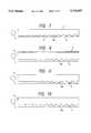
- FIG. 5is an enlarged section view of a light-conducting member used in the second embodiment.
- FIG. 6is an enlarged section view of a light-conducting member used in a third embodiment of this invention.
- FIG. 7is a sectional view of a variation of a light-conducting member used in the third embodiment.
- FIG. 8 through FIG. 10are views of variants of a light-conducting member shown in FIG. 5 through FIG. 7, respectively.
- FIG. 11is an enlarged section view of a light-conducting member used in a fourth embodiment of this invention.
- FIG. 12is an enlarged section view of a light-conducting member used in a fifth embodiment of this invention.
- FIG. 13is an enlarged section view of a light-conducting member used in a sixth embodiment of this invention.
- FIG. 14 through FIG. 16are views of variants of a light-conducting member shown in FIG. 11 through FIG. 13, respectively.
- FIG. 17is a sectional view of a seventh embodiment of this invention.
- FIG. 18is a view of a variation of the seventh embodiment of this invention.
- FIG. 19is a sectional view of an eighth embodiment of this invention.
- FIG. 20is a view of the light-conducting member as viewed from its top (from its light-emitting side).
- FIGS. 21 and 22are views of the curves of corrugations in the light-conducting member used in the eighth embodiment of this invention.
- FIG. 23 through FIG. 29are views of variants of the light-conducting member used in the eighth embodiment of this invention, respectively.
- FIG. 30is a view showing the configuration of a metal mold with rough surfaces that is used to form a light-conducting member having corresponding rough surfaces.
- FIG. 31is a view of a pattern of rough surfaces.
- FIG. 2is a sectional view of a first embodiment of a surface light source device of this invention.
- the device of FIG. 1comprises a light source 1, a light-conducting member 2, a diffusion plate 3 and a reflective plate 4.
- a pair of the light source 1are located adjacent to both ends 2a, 2d of the light-conducting member 2.
- a surface 2c of the light-conducting member 2, which is opposite to an emitting surface 2b,has a multiplicity of small depressions 5 formed thereon. Each of these depression a has a rough surface.
- the surface 2c of the light-conducting member 2has a large number of depressions 5, the direction of total reflection from the surface 2c will be altered by the depressions 5.
- the size, shape and position of the depression 5is appropriately selected, it is possible to produce a relatively uniform brightness distribution on the diffusion plate 3. Further, due to the rough surface 11 formed on the depression 5, it is possible to make more uniform the brightness distribution.
- FIG. 3is an enlarged view of a light-conducting member 2 for use in the first embodiment.
- This light-conducting member 2has a number of conical-, or pyramidal-shaped depressions 5 formed thereon. If a multiplicity of conical or pyramidal depressions are formed and their size, shape and position is appropriately selected, it is possible to provide a uniform brightness distribution on the surface light source device.
- this embodimenthas a pair of light sources.
- four units of light sourcesare used, one each on the surface 2b on four sides of the square-, or rectangular-shaped light-conducting member 2, it is possible to enhance the brightness of a surface light source device.
- only one light sourcemay be adequate for a certain need.
- This embodimenthas a disadvantage in that, as the depressions of the light-conducting member 2 have conical or pyramidal shape, only their apex or corners etc. will appear recognizably bright with emitted light.
- this inventionhas a major feature in providing depressions on the rear surface of the light-conducting member 2, as well as in the shapes etc. of these depressions.
- these depressions and their shapesare shown in expanded form in the drawings. In practice, however, the depression or projection has a size of about 0.1 to 1 mm.
- FIG. 4is a sectional view of a second embodiment of this invention.
- This embodimenthas a light source 1, a light-conducting member 2, a diffusion plate 3 and a reflective plate 4, in the same configuration as that of the surface light source device of FIG. 2.
- a surface 2chas hemispherical depressions 5 formed thereon. These depressions 5 are formed in a pattern such that the radius of curvature becomes the smallest for those which are located close to the light source 1 and gradually increases along the length of the surface 2c.
- depressions on the surface 2cmay be formed in a pattern such that they will have the increased depth along its length as they lie farther from the light source 1, with the most shallow ones close to the light source 1.
- FIG. 6is an enlarged sectional view of a third embodiment of this invention wherein a light-conducting member 2 has differently shaped depressions 6, which are of cylinderical form.
- the depressions 6have the increased dimensions as they lie farther apart from the light source 1.
- FIG. 6shows depressions 6 having a change in the length t 1 as well as depth t 2 , it is possible to achieve the same effect by changing either the length t 1 or the depth t 2 alone.
- FIG. 7is a sectional view of a variation of the third embodiment of the light-conducting member, shown in FIG. 6, wherein the light-conducting member 2 has depressions of cylindrical form, whose innermost surface 6a is spherical.
- a surface 2c of the light-conducting member 2may have projections in place of depressions. These projections may be spherical, as shown in FIG. 8, or cylindrical, as shown in FIGS. 9 and 10. These projections have the increased dimensions as they lie farther from the light source 1.
- the projections or depressions of the light-conducting member 2should preferably have rough surfaces on their surfaces 5a, 6a, 5b, 6b, respectively. Further, the roughness of the surfaces should preferably become greater as they lie farther from the light source 1.
- FIGS. 11 through 13are enlarged views of a light-conducting member for use in a fourth embodiment of this invention.
- the depressions used thereinare of conical, pyramidal, or hemispherical form, etc.
- the depressions shown in FIGS. 11 to 13may be of any shape consisting of curves, and each of the depressions has a rough surface.
- the depressionshave various sizes and depths. These depressions have different degrees of roughness. Thus, it is possible to cause the light to be uniformly emitted from the entire surface 2b.
- a surface 2c of the light-conducting member 2has depressions of the same shape and size that are equally spaced.
- This embodimenthas a depression 10 with a rough surface 11 formed thereon. Due to the distribution of these rough surfaces 11, the light emitted from the surface 2b becomes uniform throughout the surface 2b, thereby providing a uniform brightness distribution of a diffuse light that has passed through the diffusion plate 3. More particularly, the roughness of the surfaces 11 becomes greater as they lie farther from an edge surface of incidence 2a.
- the surface 2c of the light-conducting member 2has a multiplicity of depressions 10
- the light that is incident on the edge 2ais reflected from the depressions 10 and then emitted from the emitting surface 2b.
- the emitted lightpasses through the diffusion plate. 3 to form a diffuse light.
- the light that is incident on the surface 2a, but that is transmitted through the depressions 10is reflected from the reflective plate 4 and re-enter into the light-conducting member 2.
- the reflected lightis then emitted from the emitting surface 2b and passes through the diffusion plate 3 to form a diffuse light.
- the light emitted from the light-conducting member 2tends to have the declining intensity with respect to its areas lying farther from the edge surface of incidence 2a.
- this fourth embodimenthaving a distribution of depressions mentioned above, it is possible to provide a uniform brightness distribution.
- FIG. 12is a sectional view of a fifth embodiment of a light-conducting member for use in this invention, wherein depressions 12 have different sizes in different areas. More particularly, while having the same depth, the depressions 10 have the increased width as they lie farther from the edge surface of incidence. Due to the distribution of depressions as noted above, this embodiment provides a substantially uniform brightness distribution. In this embodiment, each of the depressions have substantially the same roughness.
- FIG. 13is a sectional view of a sixth embodiment of a light-conducting member for use in this invention, wherein the light-conducting member 2 has depressions 13 with different depths in different areas. More particularly, depressions 13 have the increased depths as they lie farther from the edge surface of incidence. In this way, as with the light-conducting member of FIG. 12, it is possible to cause the light to be uniformly emitted from the entire emitting surface 2b.
- FIGS. 14, 15 and 16are views of variants of the light-conducting member 2 of FIGS. 11, 12 and 13, wherein depressions 10, 12 and 13 are replaced by projections 10', 12' and 13' respectively
- the light-conducting member 2 of FIG. 14has each of projections of the same size and shape. Also, the protrusions have different roughness in different areas, as in FIG. 11. By contrast, the light-conducting member of FIGS. 15 and 16 have projections 12' or 13' of different sizes in different areas.
- the surface 2c of the light-conducting member 2has depressions or projections each of which is symmetrical with respect to its vertical center line.
- FIG. 17is a sectional view of a seventh embodiment of a light-conducting member, wherein the light-conducting member 2 has depressions 12 of asymmetrical form about the x--x line.
- This embodimentis accomplished in such a way that conical or pyramidal depressions of the light-conducting member 2 in the first embodiment of FIG. 3 are replaced by those of asymmetrical form.
- conical or pyramidal projectionsmay be replaced by those of asymmetrical form.
- symmetrical depressionsmay be replaced by those of asymmetrical form.
- projections shown thereinmay be replaced by those of asymmetrical form.
- FIG. 18is a view of a variant of the light-conducting member of FIG. 17, wherein a surface 2c of the light-conducting member is of curved form.
- the apexes 12a of the depressions 12should preferably have curved surfaces.
- the rough surfaces 11are formed only on depressions or projections of the light-conducting member 2.
- the rough surfacesmay be formed in portions between depressions or projections.
- FIG. 19is a view of an eighth embodiment of a light-conducting member.
- a surface 2c of the light-conducting member 2has smooth, continuous corrugations in all the directions along its surface.
- FIG. 19is a sectional view of the light-conducting member taken in a direction of the arrow A--A of FIG. 20, which is a plan view of the member as viewed from its top.
- the section of the surface 2c in a direction of an arrow B--B, which is at right angles to the direction of the arrow A--A,is also of corrugation.
- the section of the surface 2c in an oblique direction of the arrow C--C, set at an angle to the directions of the arrows A--A and B--Bhas also a corrugated one.
- the light that is directed onto the incidence surface 2a of the light-conducting member 2is totally reflected from the surfaces 2b and 2c as it travels toward the surface 2d. While traveling toward the surface 2d, the light is totally reflected in different directions by the provision of corrugations. Also, part of the light is refracted by, and transmitted through, the corrugations.
- the transmitted lightis reflected by the reflective plate 4 and, after having been refracted by the corrugations, it re-enters into the light-conducting member 2 passing through the corrugations.
- a diffused lighti.e., the light that has emitted through the surface 2b and then passed through the diffusion plate 3 will appear substantially uniform and in large amounts on the diffusion plate 3.
- the diffused light thus obtainedis so uniform that there occurs no bright spots at all.
- Corrugations of FIG. 19may be changed with respect to their size and shape etc.
- FIGS. 21 and 22are views of the corrugation shape.
- the corrugation shape of FIG. 21may be altered with respect to its various dimensions, such as height h, spacing between adjacent corrugations f, and incline of slope g, that is, angle ⁇ of FIG. 22.
- FIGS. 23 through 27are views of variants of a light-conducting member for use in an eighth embodiemnt of this invention, wherein corrugations of different sizes and shapes etc. are provided in different locations.
- the light-conducting member 2 of FIG. 23has corrugations with an increased height as they lie farther from the light source. Thus, a light is uniformly emitted through the surface 2b of the light-conducting member 2.
- the surface 2chas corrugations with an decreased spacing between adjacent corrugations as they lie farther from the light source.
- a lightis allowed to be uniformly emitted through the surface 2b of the light-conducting member 2.
- the light-conducting member 2 of FIG. 25is intended for use in a surface light source device wherein a pair of light sources 1 are placed adjacent both edge surfaces 2a and 2d of the light-conducting member 2.
- the surface 2c of the light-conducting member 2has corrugations in such a way that their height at both edge surfaces 2a and 2d, is the lowest and it is the highest at the center of the light-conducting member 2.
- the surface 2chas corrugations with an increased angle ⁇ of the slope g as they lie farther from the light source.
- the angle ⁇ at the edge surface 2dis 45° to 60°.
- the light-conducting member 2 of FIG. 27has an edge surface 2d opposite to an edge surface of incidence 2a, and the edge surface acts as a reflective surface. The light that is directed onto the edge surface 2a is reflected back from the opposite edge surface 2d after having reaching it. The light will not escape through the edge surface 2d. As a result, the region adjacent to a reflective plate 7 shines brightly and thus it is impossible to provide a uniform brightness distribution.
- the light-conducting member 2 of FIG. 27has a surface 2c formed with corrugations in such way that their height is the lowest for those close to the edge surface 2a and it becomes gradually higher as they lie farther away from the edge surface 2a, and then their height becomes lower toward the edge surface 2d.
- the light-conducting member 2 of FIG. 28is tapered in thickness. It has a thickest portion close to the light source and has an decreased thickness along its length.
- the tapered surface 2chas corrugations.
- the light-conducting member 2 of FIG. 29is tapered in thickness toward its center where it has a thinnest portion.
- a pair of light sourcesare positioned adjacent opposite edge surfaces of the light-conducting member 2.
- a lower surface 2chas corrugations.
- the light-conducting memberis generally made of transparent synthetic resins.
- a mold used in molding the light-conducting member of synthetic resinsshould have rough surfaces.
- an electric-discharge machining(a spark erosion process) may be used for this invention.
- a light-conducting member 2requires to have a pattern with a multiplicity of tiny spots 16, as shown in FIG. 31.
- the moldis prepared by a spark erosion process to form a corresponding pattern of spots.
- an electrode 17is maintained very close to a mold 15.
- the electrode 17 of male formhas a large number of projections 17a that correspond to tiny spots 16 in FIG. 31.
- the mold 15 and electrode 17are positioned in opposed relation.
- the mold 15is made to act as the other electrode so that the electric-spark machining is carried out.
- a surface 15a of the mold 15 which is placed very close to the electrode 17will be machined in areas facing the projections 17a of the electrode 17 to form a desired pattern of the roughness on the rough surfaces.
- the electric-spark machiningis made with the current of 3-7 A, and at a pulse duration of 5-20 microseconds.
Landscapes
- Physics & Mathematics (AREA)
- General Physics & Mathematics (AREA)
- Optics & Photonics (AREA)
- Planar Illumination Modules (AREA)
- Optical Elements Other Than Lenses (AREA)
- Liquid Crystal (AREA)
- Light Guides In General And Applications Therefor (AREA)
Abstract
Description
This is a division of application Ser. No. 07/982,942, filed Nov. 30, 1992, now U.S. Pat. No. 5,584,556.
1. Field of the Invention
This invention relates to a surface light source device to be used as a backlight for a liquid crystal display unit.
2. Description of the Prior Art
FIG. 1 shows a conventional surface light source device that has a light-conducting member. This device comprises alinear light source 1, such as a cold-cathode fluorescent tube, a light-conductingmember 2 that has an edge surface ofincidence 2a disposed adjacent thelight source 1, adiffusion plate 3 that is located on or adjacent afront surface 2b (a top surface in FIG. 1) of the light-conductingmember 2, and a reflective surface that is disposed adjacent arear surface 2c (a lower surface in FIG. 1) of thelight conducting member 2. In this surface light source device, an incident light from thesource 1 is directed toward the edge surface ofincidence 2a of the light-conductingmember 2. The light-conductingmember 2 conducts the light toward arearward edge surface 2d by total internal reflection from thesurfaces
In the conventional device, however, thesurface 2c of the light-conductingmember 2 is provided with either a roughened surface orspots 2e formed by painting to scatter part of the conducted light, in such a way that part of the light, while travelling toward thesurface 2d, spreads out from thesurface 2b without being reflected by the surface. Thus, in the surface light source device of FIG. 1, when therear surface 2c of the light-conductingmember 2 has a rough surface or forms an array ofspots 2e, as shown in FIG. 1, so that, while the incident light from thesource 1 is advanced passing through the light-conductingmember 2, part of this light spreads out from thesurface 2b and then passes through thediffusion plate 3 to form a diffused light, which is available for use as a surface light source.
In this surface light source device, it is necessary to ensure that the diffused light that has passed through thediffusion plate 3 should appear uniformly over an entire surface of thediffusion plate 3.
Also, because this surface light source device can be used, for example, as a back-light of a liquid crystal display, this requires the diffused light to be bright enough for such an application. Thus, the surface light source device is provided with means to increase the brightness.
Typical surface light source devices of the prior art that have means to increase the brightness, are disclosed in Japanese Patent Kokai Publication No. 3-189679A and Japanese Utility Kokai Publication No. 3-31782A. Like the device of FIG. 1, each of these devices comprises a light source, a light-conducting member, a diffusion plate and a reflective plate. Thesurface 2c of the light-conductingmember 2, which is opposite to the front or emittingsurface 2b, i.e. thesurface 2c adjacent to thereflective surface 4, forms a large number of minute pyramids which are arranged concavely or convexly to increase the brightness on the diffusion plate. Various sizes of these pyramids are arranged according to the area chosen to produce a uniform brightness distribution.
These prior art devices, however, have a problem in that, although it is possible to increase the brightness if the pyramid has a relatively large surface area, it is difficult to produce a uniform brightness distribution on thediffusion plate 3. Also, the pyramid formed on the light-conducting member has a disadvantage in that the light will shine at their corners.
An object of this invention is to provide a surface light source device comprising a planar light-conducting member of transparent material, a linear light source which is located adjacent at least one edge surface of the light-conducting member, a diffusion plate located on the front surface of the light-conducting member, and a reflective surface disposed on or adjacent the rear surface of the light-conducting member, characterized that the rear surface of the light-conducting member has a multiplicity of minute projections or depressions formed thereon and that these projections-or depressions have rought surfaces.
The rough surface has a multiplicity of microscopic projections and depressions, and resembles the face of a sand-paper in a configuration. The light reflected by, or transmitted through, the rough surface is scattered as a diffused light. The greater the roughness of the rough surface is, the greater the extent of the diffusion of the scattered light is. The fact that the roughness is great means that, in considering the depth and the width of both the microscopic projection and depression, and the pitch of the projections and depressions in their vertical cross-section, when both the width and the pitch are constant, the depth is great, when both the depth and the pitch are constant, the width is great, and when both the depth and the width are constant, the pitch is small.
Another object of this invention is to provide a surface light source device wherein various shapes and sizes of minute projections or depressions are formed on the rear surface of the light-conducting member, each of these projections or depressions having a rough surface.
A still another object of this invention is to provide a surface light source device wherein the rear surface of the light-conducting member has continuous corrugations, each of these corrugations having a rough surface.
FIG. 1 is a sectional view of a surface light source device of the prior art.
FIG. 2 is a sectional view of a first embodiment of this invention.
FIG. 3 is an enlarged section view of a light-conducting member used in the first embodiment.
FIG. 4 is a section view of a second embodiment of this invention.
FIG. 5 is an enlarged section view of a light-conducting member used in the second embodiment.
FIG. 6 is an enlarged section view of a light-conducting member used in a third embodiment of this invention.
FIG. 7 is a sectional view of a variation of a light-conducting member used in the third embodiment.
FIG. 8 through FIG. 10 are views of variants of a light-conducting member shown in FIG. 5 through FIG. 7, respectively.
FIG. 11 is an enlarged section view of a light-conducting member used in a fourth embodiment of this invention.
FIG. 12 is an enlarged section view of a light-conducting member used in a fifth embodiment of this invention.
FIG. 13 is an enlarged section view of a light-conducting member used in a sixth embodiment of this invention.
FIG. 14 through FIG. 16 are views of variants of a light-conducting member shown in FIG. 11 through FIG. 13, respectively.
FIG. 17 is a sectional view of a seventh embodiment of this invention.
FIG. 18 is a view of a variation of the seventh embodiment of this invention.
FIG. 19 is a sectional view of an eighth embodiment of this invention.
FIG. 20 is a view of the light-conducting member as viewed from its top (from its light-emitting side).
FIGS. 21 and 22 are views of the curves of corrugations in the light-conducting member used in the eighth embodiment of this invention.
FIG. 23 through FIG. 29 are views of variants of the light-conducting member used in the eighth embodiment of this invention, respectively.
FIG. 30 is a view showing the configuration of a metal mold with rough surfaces that is used to form a light-conducting member having corresponding rough surfaces.
FIG. 31 is a view of a pattern of rough surfaces.
FIG. 2 is a sectional view of a first embodiment of a surface light source device of this invention. The device of FIG. 1 comprises alight source 1, a light-conductingmember 2, adiffusion plate 3 and areflective plate 4. A pair of thelight source 1 are located adjacent to bothends member 2. Asurface 2c of the light-conductingmember 2, which is opposite to an emittingsurface 2b, has a multiplicity ofsmall depressions 5 formed thereon. Each of these depression a has a rough surface.
In this first embodiment, because thesurface 2c of the light-conductingmember 2 has a large number ofdepressions 5, the direction of total reflection from thesurface 2c will be altered by thedepressions 5. Thus, if the size, shape and position of thedepression 5 is appropriately selected, it is possible to produce a relatively uniform brightness distribution on thediffusion plate 3. Further, due to therough surface 11 formed on thedepression 5, it is possible to make more uniform the brightness distribution.
FIG. 3 is an enlarged view of a light-conductingmember 2 for use in the first embodiment. This light-conductingmember 2 has a number of conical-, or pyramidal-shaped depressions 5 formed thereon. If a multiplicity of conical or pyramidal depressions are formed and their size, shape and position is appropriately selected, it is possible to provide a uniform brightness distribution on the surface light source device.
As shown in FIG. 2, this embodiment has a pair of light sources. However, if four units of light sources are used, one each on thesurface 2b on four sides of the square-, or rectangular-shaped light-conductingmember 2, it is possible to enhance the brightness of a surface light source device. Alternatively, only one light source may be adequate for a certain need.
In this first embodiment, by increasing the number of light sources used and providing a light-conducting member with depressions, it is possible to provide a bright surface light source device. Also, by appropriately selecting the size etc. of the depressions, it is possible to produce a uniform brightness distribution.
This embodiment has a disadvantage in that, as the depressions of the light-conductingmember 2 have conical or pyramidal shape, only their apex or corners etc. will appear recognizably bright with emitted light.
Throughout this embodiment as well as other embodiments that will be described hereafter, this invention has a major feature in providing depressions on the rear surface of the light-conductingmember 2, as well as in the shapes etc. of these depressions. Thus, to enable clear understanding, these depressions and their shapes are shown in expanded form in the drawings. In practice, however, the depression or projection has a size of about 0.1 to 1 mm.
FIG. 4 is a sectional view of a second embodiment of this invention. This embodiment has alight source 1, a light-conductingmember 2, adiffusion plate 3 and areflective plate 4, in the same configuration as that of the surface light source device of FIG. 2. In this second embodiment, however, as shown in FIG. 5, asurface 2c hashemispherical depressions 5 formed thereon. Thesedepressions 5 are formed in a pattern such that the radius of curvature becomes the smallest for those which are located close to thelight source 1 and gradually increases along the length of thesurface 2c. In this way, by providing a multiplicity of hemispherical depressions that have differences in the radius of curvature, it is possible to make uniform a brightness distribution on thediffusion plate 3, as can be achieved in the first embodiment. Also, the problem of a local shining can be overcome as hemispherical depressions are provided.
In this embodiment, depressions on thesurface 2c may be formed in a pattern such that they will have the increased depth along its length as they lie farther from thelight source 1, with the most shallow ones close to thelight source 1.
FIG. 6 is an enlarged sectional view of a third embodiment of this invention wherein a light-conductingmember 2 has differently shapeddepressions 6, which are of cylinderical form. Thedepressions 6 have the increased dimensions as they lie farther apart from thelight source 1.
In this embodiment, while FIG. 6 showsdepressions 6 having a change in the length t1 as well as depth t2, it is possible to achieve the same effect by changing either the length t1 or the depth t2 alone.
FIG. 7 is a sectional view of a variation of the third embodiment of the light-conducting member, shown in FIG. 6, wherein the light-conductingmember 2 has depressions of cylindrical form, whoseinnermost surface 6a is spherical.
Also, as shown in FIGS. 8, 9 and 10, asurface 2c of the light-conductingmember 2 may have projections in place of depressions. These projections may be spherical, as shown in FIG. 8, or cylindrical, as shown in FIGS. 9 and 10. These projections have the increased dimensions as they lie farther from thelight source 1.
In this third embodiment, to make more uniform the brightness distribution on thediffusion plate 3, the projections or depressions of the light-conductingmember 2 should preferably have rough surfaces on theirsurfaces light source 1.
FIGS. 11 through 13 are enlarged views of a light-conducting member for use in a fourth embodiment of this invention. In the first, second and third embodiments, the depressions used therein are of conical, pyramidal, or hemispherical form, etc. By contrast, the depressions shown in FIGS. 11 to 13 may be of any shape consisting of curves, and each of the depressions has a rough surface. Further, in FIGS. 12 and 13, the depressions have various sizes and depths. These depressions have different degrees of roughness. Thus, it is possible to cause the light to be uniformly emitted from theentire surface 2b.
In the fourth embodiment of FIG. 11, asurface 2c of the light-conductingmember 2 has depressions of the same shape and size that are equally spaced. This embodiment has adepression 10 with arough surface 11 formed thereon. Due to the distribution of theserough surfaces 11, the light emitted from thesurface 2b becomes uniform throughout thesurface 2b, thereby providing a uniform brightness distribution of a diffuse light that has passed through thediffusion plate 3. More particularly, the roughness of thesurfaces 11 becomes greater as they lie farther from an edge surface ofincidence 2a.
In this fourth embodiment of FIG. 11, because thesurface 2c of the light-conductingmember 2 has a multiplicity ofdepressions 10, the light that is incident on theedge 2a is reflected from thedepressions 10 and then emitted from the emittingsurface 2b. The emitted light passes through the diffusion plate. 3 to form a diffuse light. The light that is incident on thesurface 2a, but that is transmitted through thedepressions 10 is reflected from thereflective plate 4 and re-enter into the light-conductingmember 2. The reflected light is then emitted from the emittingsurface 2b and passes through thediffusion plate 3 to form a diffuse light. In this case, the light emitted from the light-conductingmember 2 tends to have the declining intensity with respect to its areas lying farther from the edge surface ofincidence 2a. In this fourth embodiment having a distribution of depressions mentioned above, it is possible to provide a uniform brightness distribution.
FIG. 12 is a sectional view of a fifth embodiment of a light-conducting member for use in this invention, whereindepressions 12 have different sizes in different areas. More particularly, while having the same depth, thedepressions 10 have the increased width as they lie farther from the edge surface of incidence. Due to the distribution of depressions as noted above, this embodiment provides a substantially uniform brightness distribution. In this embodiment, each of the depressions have substantially the same roughness.
FIG. 13 is a sectional view of a sixth embodiment of a light-conducting member for use in this invention, wherein the light-conductingmember 2 hasdepressions 13 with different depths in different areas. More particularly,depressions 13 have the increased depths as they lie farther from the edge surface of incidence. In this way, as with the light-conducting member of FIG. 12, it is possible to cause the light to be uniformly emitted from the entire emittingsurface 2b.
FIGS. 14, 15 and 16 are views of variants of the light-conductingmember 2 of FIGS. 11, 12 and 13, whereindepressions member 2 of FIG. 14 has each of projections of the same size and shape. Also, the protrusions have different roughness in different areas, as in FIG. 11. By contrast, the light-conducting member of FIGS. 15 and 16 have projections 12' or 13' of different sizes in different areas.
In the above-mentioned embodiments, it must be noted that thesurface 2c of the light-conductingmember 2 has depressions or projections each of which is symmetrical with respect to its vertical center line.
FIG. 17 is a sectional view of a seventh embodiment of a light-conducting member, wherein the light-conductingmember 2 hasdepressions 12 of asymmetrical form about the x--x line. This embodiment is accomplished in such a way that conical or pyramidal depressions of the light-conductingmember 2 in the first embodiment of FIG. 3 are replaced by those of asymmetrical form. Alternatively, conical or pyramidal projections may be replaced by those of asymmetrical form. Further, regarding the light-conducting member of FIGS. 11 through 13, symmetrical depressions may be replaced by those of asymmetrical form. Also, regarding the light-conducting member of FIGS. 15, 16 and 17, projections shown therein may be replaced by those of asymmetrical form.
FIG. 18 is a view of a variant of the light-conducting member of FIG. 17, wherein asurface 2c of the light-conducting member is of curved form. In the embodiments of FIGS. 17 and 18, theapexes 12a of thedepressions 12 should preferably have curved surfaces.
In the first through seventh embodiments, noted above, therough surfaces 11 are formed only on depressions or projections of the light-conductingmember 2. However, the rough surfaces may be formed in portions between depressions or projections.
FIG. 19 is a view of an eighth embodiment of a light-conducting member. In this embodiment, asurface 2c of the light-conductingmember 2 has smooth, continuous corrugations in all the directions along its surface. FIG. 19 is a sectional view of the light-conducting member taken in a direction of the arrow A--A of FIG. 20, which is a plan view of the member as viewed from its top. The section of thesurface 2c in a direction of an arrow B--B, which is at right angles to the direction of the arrow A--A, is also of corrugation. Further, the section of thesurface 2c in an oblique direction of the arrow C--C, set at an angle to the directions of the arrows A--A and B--B, has also a corrugated one.
In this eighth embodiment, the light that is directed onto theincidence surface 2a of the light-conductingmember 2 is totally reflected from thesurfaces surface 2d. While traveling toward thesurface 2d, the light is totally reflected in different directions by the provision of corrugations. Also, part of the light is refracted by, and transmitted through, the corrugations.
The transmitted light is reflected by thereflective plate 4 and, after having been refracted by the corrugations, it re-enters into the light-conductingmember 2 passing through the corrugations. Thus, a diffused light, i.e., the light that has emitted through thesurface 2b and then passed through thediffusion plate 3 will appear substantially uniform and in large amounts on thediffusion plate 3. The diffused light thus obtained is so uniform that there occurs no bright spots at all.
In this embodiment, to provide a more uniform light on thediffusion plate 3, it will be effective that the corrugations have rough surfaces.
In this embodiment, there occurs no bright spots at all because thesurface 2c of the light-conductingmember 2 has continuous corrugations in all directions, as noted above. Further, it is relatively easy to provide rough surfaces for the corrugations.
Corrugations of FIG. 19 may be changed with respect to their size and shape etc. FIGS. 21 and 22 are views of the corrugation shape. The corrugation shape of FIG. 21 may be altered with respect to its various dimensions, such as height h, spacing between adjacent corrugations f, and incline of slope g, that is, angle θ of FIG. 22.
FIGS. 23 through 27 are views of variants of a light-conducting member for use in an eighth embodiemnt of this invention, wherein corrugations of different sizes and shapes etc. are provided in different locations.
The light-conductingmember 2 of FIG. 23 has corrugations with an increased height as they lie farther from the light source. Thus, a light is uniformly emitted through thesurface 2b of the light-conductingmember 2.
In the light-conductingmember 2 of FIG. 24, thesurface 2c has corrugations with an decreased spacing between adjacent corrugations as they lie farther from the light source. Thus, as in FIG. 23, a light is allowed to be uniformly emitted through thesurface 2b of the light-conductingmember 2.
The light-conductingmember 2 of FIG. 25 is intended for use in a surface light source device wherein a pair oflight sources 1 are placed adjacent bothedge surfaces member 2. Thesurface 2c of the light-conductingmember 2 has corrugations in such a way that their height at bothedge surfaces member 2.
In the light-conductingmember 2 of FIG. 26, thesurface 2c has corrugations with an increased angle θ of the slope g as they lie farther from the light source. The angle θ at theedge surface 2d is 45° to 60°.
The light-conductingmember 2 of FIG. 27 has anedge surface 2d opposite to an edge surface ofincidence 2a, and the edge surface acts as a reflective surface. The light that is directed onto theedge surface 2a is reflected back from theopposite edge surface 2d after having reaching it. The light will not escape through theedge surface 2d. As a result, the region adjacent to a reflective plate 7 shines brightly and thus it is impossible to provide a uniform brightness distribution. To provide a uniform brightness, the light-conductingmember 2 of FIG. 27 has asurface 2c formed with corrugations in such way that their height is the lowest for those close to theedge surface 2a and it becomes gradually higher as they lie farther away from theedge surface 2a, and then their height becomes lower toward theedge surface 2d.
The light-conductingmember 2 of FIG. 28 is tapered in thickness. It has a thickest portion close to the light source and has an decreased thickness along its length. The taperedsurface 2c has corrugations.
The light-conductingmember 2 of FIG. 29 is tapered in thickness toward its center where it has a thinnest portion. A pair of light sources are positioned adjacent opposite edge surfaces of the light-conductingmember 2. Alower surface 2c has corrugations.
In the light-conducting member of FIGS. 23 to 29, noted above, it is possible to provide the corrugations with rough surfaces.
Now, description will be made on means to form rough surfaces on asurface 2c of the light-conducting member in the first through eighth embodiments. The light-conducting member is generally made of transparent synthetic resins. Thus, a mold used in molding the light-conducting member of synthetic resins should have rough surfaces.
To form rough surfaces on the mold, an electric-discharge machining (a spark erosion process) may be used for this invention. As a typical example, a light-conductingmember 2 requires to have a pattern with a multiplicity oftiny spots 16, as shown in FIG. 31. The mold is prepared by a spark erosion process to form a corresponding pattern of spots.
In this process, as shown in FIG. 30, anelectrode 17 is maintained very close to amold 15. Theelectrode 17 of male form has a large number ofprojections 17a that correspond totiny spots 16 in FIG. 31. As shown in FIG. 30, themold 15 andelectrode 17 are positioned in opposed relation. Themold 15 is made to act as the other electrode so that the electric-spark machining is carried out. In this way, a surface 15a of themold 15 which is placed very close to theelectrode 17 will be machined in areas facing theprojections 17a of theelectrode 17 to form a desired pattern of the roughness on the rough surfaces. Typically, the electric-spark machining is made with the current of 3-7 A, and at a pulse duration of 5-20 microseconds. By changing the operating conditions of the electric-spark machining process, it is possible to provide different patterns of the roughness on the rough surfaces.
When a multiplicity of dots are formed on the projections or depressions of therear surface 2c of the lightconductive member 2 by printing in place of providing the rough surface on them, the extent of the diffusion of the scattered light is substantially the same as in the later ease. The fact that a number of the dots per unit area is great corresponds to that the roughness of the rough surface is great.
Claims (16)
1. A surface light source device comprising:
a light conducting member having i) a light emitting surface on one side thereof, ii) a surface opposite said light emitting surface on a side opposite said one side, thereof, and iii) an edge surface;
a reflective surface adjacent said opposite surface; and
a linear light source disposed adjacent to said edge surface of said light conducting member,
said opposite surface of said light conducting member including smooth surface portions and a plurality of projections projecting outwardly from said smooth surface portions, said projections providing rough surface portions which are rough in comparison to said smooth surface portions.
2. The surface light source device of claim 1 wherein said projections have a hemispherical shape.
3. The surface light source device of claim 1 wherein said projections have a cylindrical shape.
4. The surface light source device of claim 1 wherein said projections have a curved shape.
5. The surface light source device of any of claims 2, 3 and 4 wherein said projections have an increased size as said projects lie farther from said edge surface with the smallest projections lying adjacent to said edge surface.
6. The surface light source device of claim 1 wherein said projections are identically shaped and sized and equally spaced with respect to one another, and wherein said said rough surface portions of said projections become rougher as they lie farther from said edge surface.
7. The surface light source device of claim 1 wherein said projections have an identical diameter, and wherein said projections are distributed in such a manner that the density thereof becomes greater as said projections lie farther from said edge surface.
8. The surface light source device of claim 1 wherein said projections have an increased diameter along a length of said light conducting member, and wherein the projections of the smallest diameter lie adjacent to said edge surface of incidence.
9. A surface light source device comprising:
a linear light source;
a light-conducting member having i) a light emitting surface disposed on one side thereof, ii) a surface opposite said light emitting surface on a side opposite said one side, thereof, and iii) an edge surface disposed adjacent to said light source; and
a reflective surface disposed adjacent to said opposite surface
said device comprising corrugations formed on said opposite surface of said light-conducting member, said corrugations being defined by alternating crests and bases on said opposite surface of said light-conducting member, wherein surface portions intermediate said crests and said bases generally extend from said bases toward said crests at an angle of less than 45° with respect to the horizontal at areas adjacent said edge surface, and wherein said angle increases to within 45°-60° at areas disposed further away from said edge surface than said areas adjacent said edge surface.
10. A surface light source device comprising: a linear light source;
a light-conducting member having one edge disposed adjacent to said light source and an opposite edge, a light emitting surface disposed on one side of the light conducting member, and an opposite surface disposed on a side of said light-conducting member opposite said one side; and
a reflective surface adjacent said opposite surface of said light-conducting member;
said device comprising corrugations formed on said opposite surface of said light-conducting member, said corrugations being defined by a waveform of alternating crests and bases on said opposite surface of said light-conducting member, wherein an angle of inclination between any particular base and crest of said waveform relative to the horizontal increase as said waveform approaches said opposite edge, and is between 45° to 60° at said opposite edge.
11. A surface light source device comprising:
a light conducting member having a light-emitting surface disposed on one side thereof, an opposite surface disposed on a side opposite said one side, thereof, and an edge surface; and
a linear light source disposed adjacent to said edge surface of said light conducting member,
wherein said opposite surface of the light conducting member includes smooth surface portions and a plurality of depressed regions depressed inwardly relative to said smooth surface portions, said depressed regions providing rough surface portions which are rough in comparison with said smooth surface portions.
12. The surface light source device of claim 11 wherein said depressed regions are identically shaped and sized and equally spaced with respect to one another, and wherein said rough surface portions of said depressed regions become rougher as said rough surface portions lie farther from said edge surface.
13. The surface light source device of claim 11 wherein said depressed regions are identically shaped, and wherein said depressed regions become larger as said depressed regions lie farther from said edge surface, with the largest depressed regions lying adjacent to said edge surface.
14. The surface light source device of claim 11 wherein said depressed regions have an identical depth, and wherein said depressed regions have an increased diameter as said depressed regions lie farther from said edge surface.
15. The surface light source device of claim 11 wherein said depressed regions have an identical diameter, and wherein said depressed regions have an increased depth as said depressed regions lie farther from said edge surface.
16. A surface light source device comprising:
a light conducting member having a light-emitting surface disposed on one side thereof, an opposite surface disposed on a side opposite said one side, thereof, and an edge surface; and
a linear light source disposed adjacent to said edge surface of said light conducting member;
wherein said opposite surface of the light conducting member comprises a plurality of discreet rough surface regions separated by smooth surface regions which are smoother in comparison with said rough surface regions.
Priority Applications (1)
| Application Number | Priority Date | Filing Date | Title |
|---|---|---|---|
| US08/487,674US5718497A (en) | 1991-11-28 | 1995-06-07 | Surface light source device |
Applications Claiming Priority (14)
| Application Number | Priority Date | Filing Date | Title |
|---|---|---|---|
| JPU.M.3-105334 | 1991-11-28 | ||
| JP10533491UJPH0547922U (en) | 1991-11-28 | 1991-11-28 | Surface light source |
| JP3341747AJP2838614B2 (en) | 1991-12-02 | 1991-12-02 | How to make a light guide molding die |
| JP3-341747 | 1991-12-02 | ||
| JPU.M.4-16237 | 1992-02-20 | ||
| JP1992016237UJP2580451Y2 (en) | 1992-02-20 | 1992-02-20 | Surface light source device |
| JPU.M.4-24608 | 1992-03-25 | ||
| JP1992024601UJP2581308Y2 (en) | 1992-03-25 | 1992-03-25 | Surface light source device |
| JP2460892 | 1992-03-25 | ||
| JPU.M.4-24601 | 1992-03-25 | ||
| JP4296666AJPH06123885A (en) | 1992-10-09 | 1992-10-09 | Surface light source device |
| JP4-296666 | 1992-10-09 | ||
| US07/982,942US5584556A (en) | 1991-11-28 | 1992-11-30 | Surface light source device |
| US08/487,674US5718497A (en) | 1991-11-28 | 1995-06-07 | Surface light source device |
Related Parent Applications (1)
| Application Number | Title | Priority Date | Filing Date |
|---|---|---|---|
| US07/982,942DivisionUS5584556A (en) | 1991-11-28 | 1992-11-30 | Surface light source device |
Publications (1)
| Publication Number | Publication Date |
|---|---|
| US5718497Atrue US5718497A (en) | 1998-02-17 |
Family
ID=27548639
Family Applications (2)
| Application Number | Title | Priority Date | Filing Date |
|---|---|---|---|
| US07/982,942Expired - LifetimeUS5584556A (en) | 1991-11-28 | 1992-11-30 | Surface light source device |
| US08/487,674Expired - LifetimeUS5718497A (en) | 1991-11-28 | 1995-06-07 | Surface light source device |
Family Applications Before (1)
| Application Number | Title | Priority Date | Filing Date |
|---|---|---|---|
| US07/982,942Expired - LifetimeUS5584556A (en) | 1991-11-28 | 1992-11-30 | Surface light source device |
Country Status (3)
| Country | Link |
|---|---|
| US (2) | US5584556A (en) |
| EP (1) | EP0544332B1 (en) |
| DE (1) | DE69217177T2 (en) |
Cited By (86)
| Publication number | Priority date | Publication date | Assignee | Title |
|---|---|---|---|---|
| US5797668A (en)* | 1996-04-04 | 1998-08-25 | Dai Nippon Printing Co., Ltd. | Surface illumination device suitable for a backlit display |
| US6099135A (en)* | 1996-02-01 | 2000-08-08 | Mitsubishi Rayon Co., Ltd. | Surface light source element and liquid crystal display device, sign device and traffic control sign device using same |
| US6164791A (en)* | 1999-01-07 | 2000-12-26 | Industrial Technology Research Institute | Backlight source device |
| US6234639B1 (en)* | 1998-06-15 | 2001-05-22 | Asahi Kogaku Kogyo Kabushiki Kaisha | Polarization converter and lighting device for LCD panel |
| US6280043B1 (en)* | 1997-05-14 | 2001-08-28 | Enplas Corporation | Surface light source device of side light type |
| US6375336B1 (en)* | 1999-02-16 | 2002-04-23 | Minebea Co., Ltd. | Spread illumination apparatus |
| US6425673B1 (en)* | 1999-09-20 | 2002-07-30 | Mitsubisshi Chemical Corporation | Light guide pipe having elongate roughened protrusions and/or roughened concaves, planar light source unit having a broad viewing angle characteristic, and liquid crystal display device |
| US6502946B1 (en)* | 1999-07-21 | 2003-01-07 | Nippon Sheet Glass Co., Ltd. | Planar display lamp and method of forming a light scatterer pattern |
| US6523980B2 (en)* | 1999-05-20 | 2003-02-25 | Zumtobel Staff Gmbh | Optical element for deflecting light beams and method of production |
| US6644823B2 (en)* | 2000-07-03 | 2003-11-11 | Minebea Co., Ltd. | Spread illumination apparatus having trapezoidally-shaped grooves |
| US6672734B2 (en)* | 2000-10-25 | 2004-01-06 | Lumileds Lighting U.S., Llc | Illumination system and display device |
| US6700716B2 (en)* | 1999-05-20 | 2004-03-02 | Zumiobel Staff Gmbh | Optical element with a microprism structure for deflecting light beams |
| US20040095743A1 (en)* | 2002-11-20 | 2004-05-20 | Tai-Cheng Yu | Light guide plate |
| US6755534B2 (en) | 2001-08-24 | 2004-06-29 | Brookhaven Science Associates | Prismatic optical display |
| US20040136667A1 (en)* | 2002-12-20 | 2004-07-15 | Charles Leu | Light guide plate with diffusion dots having scattering particles and surface light source unit incorporating the light guide plate |
| US20040212757A1 (en)* | 2001-12-27 | 2004-10-28 | Lee Jeong-Hwan | Liquid crystal display apparatus |
| US20040228603A1 (en)* | 2003-03-06 | 2004-11-18 | Taiwan Nano Electro-Optical Technology Co., Ltd. | Backlighting device |
| US20040246697A1 (en)* | 2001-10-04 | 2004-12-09 | Tomoyoshi Yamashita | Area light source and lightguide used therefor |
| DE10330050A1 (en)* | 2003-07-03 | 2005-02-03 | Veutron Corporation | Background illumination module for liquid crystal display panel using light wave conductor plate illuminated via lamp adjacent its side edge with cylindrical reflectors spaced across its bottom surface |
| US20050094961A1 (en)* | 2003-10-31 | 2005-05-05 | Hon Hai Precision Industry Co., Ltd. | Light guide plate and back light system using same |
| US20050213348A1 (en)* | 1998-12-30 | 2005-09-29 | Marko Parikka | Backlighting light pipe for illuminating a flat-panel display |
| US20060056791A1 (en)* | 2002-12-20 | 2006-03-16 | Wolfgang Tzschoppe | Arrangement for two-dimensional or three-dimensional representation |
| US20060054904A1 (en)* | 2004-09-14 | 2006-03-16 | Industrial Technology Research Institute | Light emitting diode and fabrication method thereof |
| US20060062016A1 (en)* | 2004-08-24 | 2006-03-23 | Norihiro Dejima | Illumination device and display device using the same |
| US20060067084A1 (en)* | 2004-09-24 | 2006-03-30 | Schefenacker Vision Systems Germany Gmbh | Light guide for lights, in particular for motor vehicle lights |
| US20060092669A1 (en)* | 2004-10-29 | 2006-05-04 | Hon Hai Precision Industry Co., Ltd. | Backlight module with nano-material light coupling layer |
| US20060104093A1 (en)* | 2004-11-18 | 2006-05-18 | Tsinghua University | Light guide device and a backlight module using the same |
| US20060139957A1 (en)* | 2004-12-29 | 2006-06-29 | Hon Hai Precision Industry Co., Ltd. | Light guide plate having high-density dots |
| US20060203874A1 (en)* | 2005-03-12 | 2006-09-14 | Innolux Display Corp. | Backlight module and liquid crystal display having same |
| US20060203517A1 (en)* | 2002-06-26 | 2006-09-14 | Sung-Yong Kang | Backlight assembly and liquid crystal display apparatus having the same |
| US20070125634A1 (en)* | 2005-12-05 | 2007-06-07 | Samsung Electronics Co.; Ltd | Keypad and method for fabricating same |
| US20070297193A1 (en)* | 2005-03-18 | 2007-12-27 | Fujitsu Limited | Light guiding board and light source and display panel unit and electronic apparatus |
| US20080031011A1 (en)* | 2004-09-28 | 2008-02-07 | Kentaro Hayashi | Light Guide For Surface Light Source Device And Surface Light Source Device |
| US20080198626A1 (en)* | 2007-02-21 | 2008-08-21 | Wintek Corporation | Backlight module |
| CN100417989C (en)* | 2004-03-19 | 2008-09-10 | 友达光电股份有限公司 | Backlight module and light guide plate thereof |
| US20080219026A1 (en)* | 2007-03-06 | 2008-09-11 | Hon Hai Precision Industry Co., Ltd. | Light guide plate and method for making the same |
| US20090002600A1 (en)* | 2007-06-29 | 2009-01-01 | Wen-Feng Cheng | Diffusion Plate Assembly |
| US20090103310A1 (en)* | 2007-10-22 | 2009-04-23 | Sung-Nan Chen | Light Emitting Diode Illumination Device Capable of Providing Uniformly Polarized Light |
| US20090135627A1 (en)* | 2007-11-26 | 2009-05-28 | Hitachi Displays, Ltd. | Liquid crystal display device |
| US20090214828A1 (en)* | 2008-02-26 | 2009-08-27 | Vicki Herzl Watkins | Blunt tip prism film and methods for making the same |
| US20100006412A1 (en)* | 2008-07-11 | 2010-01-14 | Darfon Electronics Corp. | Keycap and press key structure using the same |
| US20100124076A1 (en)* | 2008-10-31 | 2010-05-20 | Makoto Kurihara | Illumination device and display device |
| US20100239783A1 (en)* | 2007-09-06 | 2010-09-23 | Gouping Mao | Methods of forming molds and methods of forming articles using said molds |
| US20100277949A1 (en)* | 2009-04-30 | 2010-11-04 | Coretronic Corporation | Light guide plate and backlight module |
| US20100288614A1 (en)* | 2007-09-06 | 2010-11-18 | Ender David A | Lightguides having light extraction structures providing regional control of light output |
| US20100294954A1 (en)* | 2007-12-12 | 2010-11-25 | 3M Innovative Properties Company | Method for making structures with improved edge definition |
| US20100296106A1 (en)* | 2007-10-11 | 2010-11-25 | Gates Brian J | Chromatic confocal sensor |
| US20100308497A1 (en)* | 2007-09-06 | 2010-12-09 | David Moses M | Tool for making microstructured articles |
| CN102301272A (en)* | 2008-12-18 | 2011-12-28 | 3M创新有限公司 | Light guide with enhanced light extraction |
| US20120140522A1 (en)* | 2010-12-03 | 2012-06-07 | Shinji Yagasaki | Reflecting structure, light-scattering member, light-guiding plate and lighting device |
| US20130272028A1 (en)* | 2010-12-23 | 2013-10-17 | Lg Innotek Co., Ltd. | Light guide plate for plane light source, method for manufacturing the same, and plane light source unit using the same |
| CN103388752A (en)* | 2012-07-31 | 2013-11-13 | 厦门伟然科技有限公司 | Light guide bar-type LED (light emitting diode) daylight lamp |
| US8605256B2 (en) | 2008-02-26 | 2013-12-10 | 3M Innovative Properties Company | Multi-photon exposure system |
| US8646194B2 (en)* | 2004-10-29 | 2014-02-11 | George O. Podd | Lighting device |
| US20140355302A1 (en)* | 2013-03-15 | 2014-12-04 | Cree, Inc. | Outdoor and/or Enclosed Structure LED Luminaire for General Illumination Applications, Such as Parking Lots and Structures |
| US20140355290A1 (en)* | 2013-05-31 | 2014-12-04 | Kyocera Document Solutions Inc. | Light guide and illumination device |
| US20150055373A1 (en)* | 2013-08-23 | 2015-02-26 | Hon Hai Precision Industry Co., Ltd. | Light guide plate and method for manufacturing same |
| US20150109820A1 (en)* | 2013-03-15 | 2015-04-23 | Cree, Inc. | Outdoor and/or Enclosed Structure LED Luminaire |
| CN104714269A (en)* | 2013-12-17 | 2015-06-17 | 三星显示有限公司 | Light guide panel, backlight unit and liquid crystal display comprising the same |
| US20150168630A1 (en)* | 2013-12-17 | 2015-06-18 | Samsung Display Co. Ltd. | Light guide panel, backlight unit, and liquid crystal display |
| US20150345715A1 (en)* | 2014-05-30 | 2015-12-03 | Cree, Inc. | LED Luminaire and Components Therefor |
| US9214101B2 (en) | 2013-02-14 | 2015-12-15 | Mark Richmond | Backlit graphic display device |
| US9291320B2 (en) | 2013-01-30 | 2016-03-22 | Cree, Inc. | Consolidated troffer |
| US9343003B2 (en)* | 2004-10-29 | 2016-05-17 | George O. Podd | Backlit graphic display device with device-to-surface mounts |
| US9366396B2 (en) | 2013-01-30 | 2016-06-14 | Cree, Inc. | Optical waveguide and lamp including same |
| US9366799B2 (en) | 2013-03-15 | 2016-06-14 | Cree, Inc. | Optical waveguide bodies and luminaires utilizing same |
| US9389367B2 (en) | 2013-01-30 | 2016-07-12 | Cree, Inc. | Optical waveguide and luminaire incorporating same |
| US9442243B2 (en) | 2013-01-30 | 2016-09-13 | Cree, Inc. | Waveguide bodies including redirection features and methods of producing same |
| US9625638B2 (en) | 2013-03-15 | 2017-04-18 | Cree, Inc. | Optical waveguide body |
| USD790096S1 (en) | 2015-12-02 | 2017-06-20 | MotorMood, LLC | Vehicular illuminated display device |
| US9690029B2 (en) | 2013-01-30 | 2017-06-27 | Cree, Inc. | Optical waveguides and luminaires incorporating same |
| US9798072B2 (en) | 2013-03-15 | 2017-10-24 | Cree, Inc. | Optical element and method of forming an optical element |
| US9869432B2 (en) | 2013-01-30 | 2018-01-16 | Cree, Inc. | Luminaires using waveguide bodies and optical elements |
| US9920901B2 (en) | 2013-03-15 | 2018-03-20 | Cree, Inc. | LED lensing arrangement |
| US20180095330A1 (en)* | 2015-04-07 | 2018-04-05 | Corning Incorporated | Texture gradient for uniform light output from a transparent backlight |
| US20180249149A1 (en)* | 2015-03-26 | 2018-08-30 | Koninklijke Philips N.V. | Display device with directional control of the output, and a backlight for such a display device and a light direction method |
| US10180527B2 (en) | 2014-03-19 | 2019-01-15 | Sharp Kabushiki Kaisha | Lighting device and display device |
| US10209429B2 (en) | 2013-03-15 | 2019-02-19 | Cree, Inc. | Luminaire with selectable luminous intensity pattern |
| US10416377B2 (en) | 2016-05-06 | 2019-09-17 | Cree, Inc. | Luminaire with controllable light emission |
| US10436970B2 (en) | 2013-03-15 | 2019-10-08 | Ideal Industries Lighting Llc | Shaped optical waveguide bodies |
| US11112083B2 (en) | 2013-03-15 | 2021-09-07 | Ideal Industries Lighting Llc | Optic member for an LED light fixture |
| US20230161127A1 (en)* | 2020-04-15 | 2023-05-25 | CommScope Connectivity Belgium BV | Device and method for sealing cables in telecommunications enclosures |
| US20230213163A1 (en)* | 2020-10-16 | 2023-07-06 | Ningbo Geely Automobile Research & Development Co., Ltd. | Optical lens system for vehicle lighting applications |
| US11719882B2 (en) | 2016-05-06 | 2023-08-08 | Ideal Industries Lighting Llc | Waveguide-based light sources with dynamic beam shaping |
| US11719874B2 (en) | 2021-12-02 | 2023-08-08 | Zkw Group Gmbh | Light guide |
| US12372219B2 (en)* | 2014-05-30 | 2025-07-29 | Cree Lighting Usa Llc | LED luminaire with a cavity, finned interior, and a curved outer wall extending from a surface on which the light source is mounted |
Families Citing this family (198)
| Publication number | Priority date | Publication date | Assignee | Title |
|---|---|---|---|---|
| US5349503A (en)* | 1991-12-31 | 1994-09-20 | At&T Bell Laboratories | Illuminated transparent display with microtextured back reflector |
| JPH06314069A (en)* | 1993-03-03 | 1994-11-08 | Fujitsu Ltd | Lighting equipment |
| US5863113A (en)* | 1993-06-22 | 1999-01-26 | Mitsubishi Rayon Co., Ltd. | Plane light source unit |
| AU680265B2 (en)* | 1993-08-18 | 1997-07-24 | Ramasoft3 Pty Limited | Optical fibre flat screen |
| EP0727678B1 (en)* | 1993-11-05 | 2003-03-26 | Enplas Corporation | Surface light source device |
| JPH07270603A (en)* | 1994-03-29 | 1995-10-20 | Enplas Corp | Optical control member |
| DE69522183T2 (en)* | 1994-12-16 | 2002-04-25 | Canon Kk | Lighting device and liquid crystal display containing the same |
| EP0726695A3 (en)* | 1995-02-07 | 1997-08-20 | Matsushita Electric Industrial Co Ltd | Lighting method and associated apparatus |
| US7108414B2 (en) | 1995-06-27 | 2006-09-19 | Solid State Opto Limited | Light emitting panel assemblies |
| US6712481B2 (en)* | 1995-06-27 | 2004-03-30 | Solid State Opto Limited | Light emitting panel assemblies |
| JP3368110B2 (en)* | 1995-08-01 | 2003-01-20 | キヤノン株式会社 | Light source device and optical equipment |
| EP0781959A1 (en)* | 1995-12-28 | 1997-07-02 | AT&T Corp. | Transparent display with diffuser-backed microtextured illuminating device and method of manufacture therefor |
| US5961198A (en)* | 1996-02-02 | 1999-10-05 | Hitachi, Ltd. | Liquid crystal display device and method of manufacturing backlighting light guide panel therefor |
| US5838403A (en)* | 1996-02-14 | 1998-11-17 | Physical Optics Corporation | Liquid crystal display system with internally reflecting waveguide for backlighting and non-Lambertian diffusing |
| US6072551A (en)* | 1996-02-14 | 2000-06-06 | Physical Optics Corporation | Backlight apparatus for illuminating a display with controlled light output characteristics |
| JP3473882B2 (en)* | 1996-02-20 | 2003-12-08 | 株式会社エンプラス | Light guide plate and side light type surface light source device |
| US5980054A (en)* | 1996-05-09 | 1999-11-09 | Matsushita Electric Industrial Co., Ltd. | Panel-form illuminating system |
| US6002464A (en)* | 1996-05-13 | 1999-12-14 | Kuraray Co., Ltd. | Light diffusing sheet having a layer incorporated with light diffusing material and a layer with a corrugated surface |
| US5897184A (en)* | 1996-07-02 | 1999-04-27 | Dimension Technologies, Inc. | Reduced-thickness backlighter for autostereoscopic display and display using the backlighter |
| US5831698A (en)* | 1996-08-20 | 1998-11-03 | International Business Machines Corporation | Electrically variable diffuser |
| US6264343B1 (en)* | 1996-11-14 | 2001-07-24 | Seiko Epson Corporation | Input tablet and liquid crystal display device utilizing such tablet |
| NO965312L (en)* | 1996-12-11 | 1998-06-12 | Skiltprodusenten G O Mekaniske | Device for illuminating traffic signs, advertising signs, information signs and the like |
| DE19652209A1 (en)* | 1996-12-16 | 1998-06-18 | Bosch Gmbh Robert | Lighting unit |
| US6334689B1 (en) | 1997-01-30 | 2002-01-01 | Hitachi, Ltd. | Liquid crystal display |
| US6478438B1 (en) | 1997-02-14 | 2002-11-12 | Enplas Corporation | Side light type surface light source device |
| US6879354B1 (en)* | 1997-03-28 | 2005-04-12 | Sharp Kabushiki Kaisha | Front-illuminating device and a reflection-type liquid crystal display using such a device |
| WO1998058282A2 (en)* | 1997-06-17 | 1998-12-23 | Baker Electronivcs, Inc. | Optimized highly efficient large area modular flat panel display lighting device |
| US6154595A (en)* | 1997-07-14 | 2000-11-28 | Matsushita Electric Works, Ltd. | Side-face illuminating optical fiber |
| US6036327A (en)* | 1997-07-28 | 2000-03-14 | Lucent Technologies Inc. | Transparent display with diffuser backed microtextured illuminating device and method of manufacture therefor |
| JP3257457B2 (en)* | 1997-07-31 | 2002-02-18 | 株式会社日立製作所 | Liquid crystal display |
| DE29716013U1 (en)* | 1997-09-06 | 1997-10-23 | Hella Kg Hueck & Co | Lighting device |
| US6164805A (en)* | 1998-04-20 | 2000-12-26 | Federal-Mogul World Wide, Inc. | Illuminated door handle for a vehicle |
| US6168302B1 (en) | 1997-12-09 | 2001-01-02 | Cooper Automotive Products, Inc. | Hybrid distributed lighting system for a vehicle |
| US6193399B1 (en) | 1997-12-09 | 2001-02-27 | Cooper Automotive Products, Inc. | Optical waveguide structures for vehicle lighting |
| FR2776811B1 (en)* | 1998-03-25 | 2001-12-14 | Christophe Blanc | ILLUMINATED LIGHTING DEVICE |
| TW412646B (en)* | 1998-06-02 | 2000-11-21 | Nissha Printing | Front light-combined touch panel device |
| WO1999066355A2 (en)* | 1998-06-19 | 1999-12-23 | Fiberstars, Inc. | Lighting fixture for fiber optics and method |
| TW523627B (en) | 1998-07-14 | 2003-03-11 | Hitachi Ltd | Liquid crystal display device |
| JP2000111900A (en)* | 1998-10-02 | 2000-04-21 | Sony Corp | Reflective display |
| US6430339B1 (en)* | 1998-10-15 | 2002-08-06 | Federal-Mogul World Wide, Inc. | Low profile waveguide system |
| JP3839998B2 (en)* | 1998-10-28 | 2006-11-01 | シャープ株式会社 | Backlight |
| TW422346U (en)* | 1998-11-17 | 2001-02-11 | Ind Tech Res Inst | A reflector device with arc diffusion uint |
| US6256447B1 (en) | 1998-12-31 | 2001-07-03 | Physical Optics Corporation | Backlight for correcting diagonal line distortion |
| US6402334B1 (en)* | 1999-02-18 | 2002-06-11 | Garmin Corporation | Light pipe with quadraspherical depressions for display panels |
| US6752505B2 (en)* | 1999-02-23 | 2004-06-22 | Solid State Opto Limited | Light redirecting films and film systems |
| WO2000050808A1 (en)* | 1999-02-24 | 2000-08-31 | 3M Innovative Properties Company | Illumination device for producing predetermined intensity patterns |
| AU2003203437B2 (en)* | 1999-03-26 | 2006-12-21 | Nebbel Pty Ltd | Display device |
| AUPP944699A0 (en)* | 1999-03-26 | 1999-04-22 | B.T.B.H. Holdings Limited | A display system |
| KR20010001951A (en) | 1999-06-10 | 2001-01-05 | 구본준 | A reflection type liquid crystal display device with a surface light source device. |
| JP2000352719A (en)* | 1999-06-14 | 2000-12-19 | Nec Corp | Light guide plate for liquid crystal display device, and its production |
| AU1468200A (en)* | 1999-07-01 | 2001-01-22 | 3M Innovative Properties Company | Display assembly having a front light guide |
| JP3570708B2 (en)* | 1999-09-10 | 2004-09-29 | 株式会社エンプラス | Light guide plate, side light type surface light source device and liquid crystal display device |
| DE50012190D1 (en)* | 1999-12-01 | 2006-04-20 | Siteco Beleuchtungstech Gmbh | Optical fiber lamp with a non-uniform refractive structure |
| FR2802308B1 (en) | 1999-12-09 | 2002-03-08 | Gc Comm | LASER MACHINING METHOD AND DEVICE FOR LIGHT GUIDES, LIGHT GUIDES OBTAINED AND BACKLIGHT SCREENS INCORPORATING THESE GUIDES |
| JP2001194534A (en) | 2000-01-13 | 2001-07-19 | Nitto Denko Corp | Light guide plate and method of manufacturing the same |
| EP1143270B1 (en)* | 2000-01-13 | 2007-03-14 | Nitto Denko Corporation | Optical film and liquid-crystal display device |
| EP1143269B1 (en)* | 2000-01-13 | 2007-03-14 | Nitto Denko Corporation | Optical path changing polarizer |
| CA2436596C (en)* | 2000-01-25 | 2005-10-25 | 4D-Vision Gmbh | Method and arrangement for the three-dimensional display |
| JP4609962B2 (en)* | 2000-02-02 | 2011-01-12 | 日東電工株式会社 | Optical film |
| JP4442836B2 (en) | 2000-02-02 | 2010-03-31 | 日東電工株式会社 | Optical film |
| JP2001228315A (en)* | 2000-02-14 | 2001-08-24 | Nitto Denko Corp | Reflector and liquid crystal display |
| DE10053867B4 (en)* | 2000-03-15 | 2006-01-12 | X3D Technologies Gmbh | lighting device |
| TW514709B (en)* | 2000-05-04 | 2002-12-21 | Koninkl Philips Electronics Nv | Illumination system and display device |
| US6331915B1 (en)* | 2000-06-13 | 2001-12-18 | Kenneth J. Myers | Lighting element including light emitting diodes, microprism sheet, reflector, and diffusing agent |
| KR20020041431A (en)* | 2000-07-11 | 2002-06-01 | 미우라 아키라 | Surface light source device |
| JP2002131552A (en) | 2000-10-24 | 2002-05-09 | Nitto Denko Corp | Light guide plate, surface light source device and reflection type liquid crystal display device |
| US6485166B1 (en)* | 2000-10-31 | 2002-11-26 | Acuity Brands, Inc. | Plastic globe for use in lighting applications and method of making same |
| KR100432438B1 (en)* | 2001-01-18 | 2004-05-22 | 주식회사 송산 | Prism Diffuser |
| JP4662402B2 (en) | 2001-03-12 | 2011-03-30 | 日東電工株式会社 | Light guide plate for front light for both external light and illumination modes, surface light source device for front light for both external light and illumination modes, and front light type reflective liquid crystal display device for both external light and illumination modes |
| US6471379B2 (en) | 2001-03-21 | 2002-10-29 | Federal-Mogul World Wide, Inc. | Waveguide illumination assembly for an automobile license plate |
| KR100799156B1 (en)* | 2001-07-13 | 2008-01-29 | 삼성전자주식회사 | Light guide plate, manufacturing method thereof, liquid crystal display device using the same |
| CN100392495C (en)* | 2001-07-27 | 2008-06-04 | 株式会社恩普乐 | Surface light source device and light guide plate |
| JP4049624B2 (en) | 2001-07-27 | 2008-02-20 | 株式会社エンプラス | Surface light source device, image display device, and light guide plate |
| US6827460B2 (en)* | 2001-08-03 | 2004-12-07 | Casio Computer Co., Ltd. | Lighting panel having light-collecting function and display device using same |
| JP3823289B2 (en)* | 2001-09-21 | 2006-09-20 | ミネベア株式会社 | Surface lighting device |
| US6796700B2 (en) | 2002-02-02 | 2004-09-28 | Edward Robert Kraft | Flat panel luminaire with remote light source and hollow light pipe for back lit signage applications |
| AU2003210819A1 (en)* | 2002-02-02 | 2003-09-02 | Edward R. Kraft | Light emitting flat panel with embedded light guides for general lighting luminaire |
| US6908204B2 (en) | 2002-02-02 | 2005-06-21 | Edward Robert Kraft | Flat panel luminaire having embedded light guides |
| FI20020761A0 (en)* | 2002-04-19 | 2002-04-19 | Nokia Corp | Method for making a plastic molded indicator symbol and a plastic molded indicator symbol |
| JP2004061922A (en)* | 2002-07-30 | 2004-02-26 | Sony Corp | Light reflection display method, light reflection display device and electronic equipment |
| KR100472468B1 (en)* | 2002-08-07 | 2005-03-10 | 삼성전자주식회사 | Optical guide and image forming apparatus employing it |
| TW587708U (en)* | 2002-12-17 | 2004-05-11 | Hon Hai Prec Ind Co Ltd | Large size light guide plate and surface lighting system using the same |
| DE10261657A1 (en)* | 2002-12-20 | 2004-07-01 | X3D Technologies Gmbh | Arrangement for 2D or 3D representation has second mode in which light from radiation plane between filter array and image reproduction device passes through reproduction device but not filter array |
| TWI280427B (en)* | 2003-01-29 | 2007-05-01 | Hon Hai Prec Ind Co Ltd | Back light module |
| US7278766B2 (en)* | 2003-04-04 | 2007-10-09 | Honeywell International Inc. | LED based light guide for dual mode aircraft formation lighting |
| DE10325146A1 (en) | 2003-05-30 | 2004-12-16 | X3D Technologies Gmbh | Method and arrangement for spatial representation |
| TWM243658U (en)* | 2003-06-13 | 2004-09-11 | Hon Hai Prec Ind Co Ltd | Planar light source device |
| TWI461758B (en)* | 2003-08-13 | 2014-11-21 | Sumitomo Chemical Co | Method for preparing anti-glare optical film |
| JP4273930B2 (en)* | 2003-10-31 | 2009-06-03 | ソニー株式会社 | Light guide plate and backlight device |
| KR100971392B1 (en)* | 2003-12-24 | 2010-07-21 | 엘지디스플레이 주식회사 | LCD Display |
| JP2005276453A (en)* | 2004-03-23 | 2005-10-06 | Yowa:Kk | Light source plate for surface light source |
| EP1780464A4 (en)* | 2004-08-06 | 2009-08-19 | Kuraray Co | LIGHT GUIDE PLATE, MANUFACTURING METHOD THEREFOR, AND SUPERFICIAL LIGHT SOURCE DEVICE WITH SAID PLATE |
| KR101133756B1 (en)* | 2004-08-30 | 2012-04-09 | 삼성전자주식회사 | A light guiding plate and a backlight assembly and a liquid crystal display provided with the same |
| JP4220479B2 (en)* | 2004-09-02 | 2009-02-04 | 鴻富錦精密工業(深▲セン▼)有限公司 | Light guide plate and backlight module |
| US20060077555A1 (en)* | 2004-10-08 | 2006-04-13 | Chen Ching W | Diffuse optical films |
| US20060104089A1 (en)* | 2004-11-18 | 2006-05-18 | Tsinghua University | Light guide plate and a backlight module using the same |
| US7908080B2 (en) | 2004-12-31 | 2011-03-15 | Google Inc. | Transportation routing |
| US7284893B2 (en)* | 2005-03-09 | 2007-10-23 | K-Bridge Electronics Co., Ltd. | Light equalizing structure of backlight modules |
| EP1875126A4 (en)* | 2005-04-29 | 2009-08-05 | Eveready Battery Inc | A light distributor |
| KR101253057B1 (en)* | 2005-07-07 | 2013-04-10 | 삼성디스플레이 주식회사 | Liquid Crystal Display |
| JP4548254B2 (en)* | 2005-07-21 | 2010-09-22 | オムロン株式会社 | Surface light source device |
| US20070171529A1 (en)* | 2005-10-26 | 2007-07-26 | Speed Tech Corp. | Method for manufacturing optical element |
| TW200725076A (en)* | 2005-12-29 | 2007-07-01 | Speed Tech Corp | Method of adjusting diffusing and condensing light ability of optical element |
| WO2007080772A1 (en)* | 2006-01-10 | 2007-07-19 | Rohm Co., Ltd. | Light guiding member and linear light source apparatus using same |
| ITMI20061203A1 (en)* | 2006-06-22 | 2007-12-23 | X | X |
| JP4695626B2 (en)* | 2006-06-30 | 2011-06-08 | 株式会社東芝 | Illumination device and liquid crystal display device |
| TWI301533B (en)* | 2006-08-14 | 2008-10-01 | Ind Tech Res Inst | Optical diffusion module |
| TWI295355B (en)* | 2006-08-30 | 2008-04-01 | Ind Tech Res Inst | Optical diffusion module and method of manufacturing optical diffusion structure |
| US8620422B2 (en)* | 2006-09-28 | 2013-12-31 | Cvrx, Inc. | Electrode array structures and methods of use for cardiovascular reflex control |
| EP2080045A1 (en) | 2006-10-20 | 2009-07-22 | Pixtronix Inc. | Light guides and backlight systems incorporating light redirectors at varying densities |
| DE202006017445U1 (en)* | 2006-11-14 | 2007-08-02 | Demmel Ag | Light module, in particular for a backlit lettering in a front panel |
| CN101191862A (en)* | 2006-11-20 | 2008-06-04 | 鸿富锦精密工业(深圳)有限公司 | Optical plate and its preparation method |
| GB2443849A (en)* | 2006-11-20 | 2008-05-21 | Sharp Kk | Backlight and display |
| US7967495B2 (en)* | 2007-01-17 | 2011-06-28 | Toyoda Gosei Co., Ltd. | Scuff plate |
| TWI368082B (en)* | 2007-03-15 | 2012-07-11 | Au Optronics Corp | Display panel |
| DE102007015747A1 (en)* | 2007-03-30 | 2008-10-02 | Erich Utsch Ag | Optical fiber arrangement for mounting device for illuminating retroreflecting vehicle number plate, has laminar expanded transparent optical fiber with front side light transmission surface and rear side light transmission surface |
| WO2008135072A1 (en)* | 2007-05-04 | 2008-11-13 | Noctron Soparfi S.A. | Lighting device and liquid crystal screen having such a lighting device |
| US20080292871A1 (en)* | 2007-05-22 | 2008-11-27 | Cheng-Hsin Yeh | Optical Film Device |
| CN101339268B (en)* | 2007-07-06 | 2011-07-27 | 鸿富锦精密工业(深圳)有限公司 | Backlight module group and its optical plate |
| JP2009075253A (en)* | 2007-09-19 | 2009-04-09 | Nippon Sheet Glass Co Ltd | Line illuminating unit |
| TWI363900B (en) | 2007-10-04 | 2012-05-11 | Ind Tech Res Inst | Light guiding film |
| JP4935627B2 (en)* | 2007-10-30 | 2012-05-23 | ソニー株式会社 | OPTICAL ELEMENT AND METHOD FOR PRODUCING OPTICAL ELEMENT MANUFACTURING MASTER |
| TW200921733A (en)* | 2007-11-08 | 2009-05-16 | Chicony Electronics Co Ltd | Energy-efficient light-emitting module |
| US8248560B2 (en) | 2008-04-18 | 2012-08-21 | Pixtronix, Inc. | Light guides and backlight systems incorporating prismatic structures and light redirectors |
| GB0809385D0 (en)* | 2008-05-23 | 2008-07-02 | Design Led Products Ltd | Light-guide apparatus |
| TWM347535U (en)* | 2008-06-17 | 2008-12-21 | yun-heng Xu | Structural improvement of light guide plate |
| JP2010008569A (en)* | 2008-06-25 | 2010-01-14 | Brother Ind Ltd | Destaticizer and process cartridge |
| TWI418855B (en)* | 2008-08-28 | 2013-12-11 | Ind Tech Res Inst | Illuminant module with an optical film of multiple curvatures |
| TWI363888B (en)* | 2008-09-22 | 2012-05-11 | Au Optronics Corp | Light guide plate, backlight module and liquid crystal dislay |
| EP2184628A3 (en) | 2008-11-06 | 2010-10-06 | CEAG Notlichtsysteme GmbH | Lights, in particular emergency, rescue or safety lights |
| US8070341B2 (en)* | 2008-12-18 | 2011-12-06 | Visteon Global Technologies, Inc. | Light pipe with uniformly lit appearance |
| US20110019130A1 (en)* | 2009-07-24 | 2011-01-27 | Jun Seok Park | Lcd including led |
| TWI409544B (en)* | 2009-11-23 | 2013-09-21 | Global Lighting Technologies | Method and Structure of Luminous Homogenization of Backlight Module |
| TW201124007A (en)* | 2009-12-30 | 2011-07-01 | Au Optronics Corp | Substrate and substrate bonding device using the same |
| JP5028501B2 (en)* | 2010-01-20 | 2012-09-19 | 株式会社ジャパンディスプレイイースト | Liquid crystal display |
| US20110219648A1 (en)* | 2010-03-12 | 2011-09-15 | Trevor James | Led edge-lit signage utilizing digital print technology |
| TWI413820B (en)* | 2010-04-01 | 2013-11-01 | Young Lighting Technology Corp | Lighting apparatus and light guide plate |
| KR101767452B1 (en)* | 2010-07-05 | 2017-08-14 | 삼성디스플레이 주식회사 | Backlight unit of liquid crystal display |
| CN102011981B (en)* | 2010-09-27 | 2012-06-27 | 友达光电股份有限公司 | Display with switchable viewing angle and backlight module thereof |
| US9134008B2 (en)* | 2010-10-06 | 2015-09-15 | Shoot The Moon Products Ii, Llc | Light emitting decorative panels |
| US9200781B2 (en) | 2010-10-06 | 2015-12-01 | Shoot The Moon Products Ii, Llc | Light emitting decorative panels |
| KR101724065B1 (en)* | 2010-11-01 | 2017-04-07 | 삼성전자주식회사 | Directional waveguide plate, directional surface light source, and 3D image display apparatus employing the directional surface light source |
| US8562167B1 (en) | 2010-11-05 | 2013-10-22 | Peter Meier Inc, Llc | Cabinet having a light-emitting-translucent-shelf |
| JP2013012422A (en)* | 2011-06-30 | 2013-01-17 | Hitachi Consumer Electronics Co Ltd | Backlight device, and liquid crystal display device using the same |
| JP5753012B2 (en)* | 2011-07-05 | 2015-07-22 | 株式会社小糸製作所 | Vehicle lighting |
| JP5776401B2 (en)* | 2011-07-21 | 2015-09-09 | セイコーエプソン株式会社 | Liquid crystal display device, electronic device and lighting device |
| US9303204B2 (en)* | 2011-11-30 | 2016-04-05 | Chin Piao Kuo | Planar light source device and method of manufacturing same |
| TWI553358B (en)* | 2011-12-23 | 2016-10-11 | 鴻海精密工業股份有限公司 | Light guide plate and backlight module using the same |
| CN103176238B (en)* | 2011-12-26 | 2017-03-01 | 鸿富锦精密工业(深圳)有限公司 | Light guide plate and backlight module using the same |
| CN103176637B (en)* | 2011-12-26 | 2016-06-08 | 群康科技(深圳)有限公司 | The manufacture method of display panel and decoration frame thereof and the touch control display system of application |
| FR2985300A1 (en)* | 2012-01-04 | 2013-07-05 | Peugeot Citroen Automobiles Sa | PROTECTIVE DEVICE PROVIDING AT LEAST ONE LIGHT TRANSFER LIGHTING FUNCTION USING DEFINED STIFFEN (S) IN A TRANSPARENT WALL |
| JP5553077B2 (en)* | 2012-03-15 | 2014-07-16 | オムロン株式会社 | Surface light source device |
| US9442240B2 (en)* | 2012-03-16 | 2016-09-13 | Radiant Opto-Electronics Corporation | Light guide plate and light source module |
| DE102012103997B4 (en)* | 2012-05-07 | 2023-07-27 | HELLA GmbH & Co. KGaA | Lighting device for vehicles |
| US9976724B2 (en)* | 2012-06-11 | 2018-05-22 | Energizer Brands, Llc | Lighting device construction |
| WO2013188278A1 (en) | 2012-06-11 | 2013-12-19 | Eveready Battery Company, Inc | A lighting device and light panel construction |
| KR20140020493A (en)* | 2012-08-08 | 2014-02-19 | 삼성디스플레이 주식회사 | Light guide plate and manufacturing method of the same |
| TWI490607B (en) | 2012-10-15 | 2015-07-01 | 群康科技(深圳)有限公司 | Display apparatus and light emitting module and light-guiding plate thereof |
| TWI485483B (en)* | 2012-10-16 | 2015-05-21 | Innocom Tech Shenzhen Co Ltd | Light-guiding plate, light emitting module and display apparatus |
| TWI475301B (en)* | 2012-10-16 | 2015-03-01 | Innocom Tech Shenzhen Co Ltd | Light emitting module and display apparatus |
| US9133989B2 (en)* | 2012-12-15 | 2015-09-15 | Lumenetix, Inc. | Mechanical attachment system for linear light modules |
| JP6143467B2 (en)* | 2013-01-10 | 2017-06-07 | 株式会社ジャパンディスプレイ | Liquid crystal display |
| US20140192521A1 (en)* | 2013-01-10 | 2014-07-10 | Ledil Oy | Light guide element |
| TW201430457A (en)* | 2013-01-24 | 2014-08-01 | Hon Hai Prec Ind Co Ltd | Liquid crystal display device |
| CN104006353A (en)* | 2013-02-22 | 2014-08-27 | 扬升照明股份有限公司 | Reflector, light source module and display device |
| US20140268879A1 (en)* | 2013-03-14 | 2014-09-18 | Panasonic Corporation | Transparent waveguide diffuser for lighting and methods of manufacturing transparent waveguide diffuser |
| JP5956953B2 (en)* | 2013-05-17 | 2016-07-27 | カルソニックカンセイ株式会社 | Light guide for light emitting pointer |
| TWI500985B (en)* | 2013-07-23 | 2015-09-21 | Cheng Tao Lee | Light guide |
| US9239420B2 (en)* | 2013-07-26 | 2016-01-19 | Dai Nippon Printing Co., Ltd. | Light guide plate, surface source device and transmission-type display device |
| DE102013220122A1 (en)* | 2013-10-04 | 2015-04-09 | Automotive Lighting Reutlingen Gmbh | Light guide for automotive lighting device |
| TWI500982B (en)* | 2013-10-09 | 2015-09-21 | Avision Inc | Dual-slope light guide, light source module and optical assembly for scanner |
| KR102147938B1 (en)* | 2013-12-27 | 2020-08-25 | 엘지이노텍 주식회사 | Lighting device |
| KR102147940B1 (en) | 2013-12-27 | 2020-08-25 | 엘지이노텍 주식회사 | Lighting device |
| CN104932140B (en)* | 2014-03-21 | 2017-12-26 | 扬升照明股份有限公司 | Backlight module |
| US9958602B2 (en) | 2014-06-13 | 2018-05-01 | Lutron Electronics Co., Inc. | Device with illuminated light bar |
| JP6190790B2 (en)* | 2014-10-15 | 2017-08-30 | ミネベアミツミ株式会社 | Surface lighting device |
| CN104566181B (en)* | 2015-01-15 | 2017-06-06 | 华南理工大学 | One kind is without light guide plate natural light flat lamp |
| JP2018510468A (en)* | 2015-04-02 | 2018-04-12 | フィリップス ライティング ホールディング ビー ヴィ | Illumination system using light guide and illumination method |
| TWI698403B (en)* | 2015-05-15 | 2020-07-11 | 美商康寧公司 | Glass article comprising light extraction features and methods for making the same |
| CN105137524B (en)* | 2015-06-10 | 2017-12-29 | 深圳市华星光电技术有限公司 | Liquid crystal display device and its light guide plate |
| WO2017029281A1 (en)* | 2015-08-20 | 2017-02-23 | Philips Lighting Holding B.V. | An optical element and lighting system utilizing the same |
| EP3360150B1 (en)* | 2015-10-09 | 2021-04-28 | Lutron Technology Company LLC | Wireless control device having a faceplate with illuminated indicia |
| TWI616246B (en)* | 2017-05-03 | 2018-03-01 | 達方電子股份有限公司 | Light-guiding device and manufacture therof by use of rolling article |
| CN109116571A (en)* | 2017-06-22 | 2019-01-01 | 台达电子工业股份有限公司 | Stereoscopic display apparatus capable of being used vertically and horizontally |
| US10591660B2 (en) | 2017-09-09 | 2020-03-17 | Svv Technology Innovations, Inc. | Wide-area solid-state illumination devices and systems |
| GB2566711B (en)* | 2017-09-22 | 2020-08-19 | Visteon Global Tech Inc | A backlight panel for providing area backlighting of a panel display device |
| US20190154904A1 (en)* | 2017-11-21 | 2019-05-23 | Wuhan China Star Optoelectronics Technology Co., Ltd. | Array substrate and fabricating method thereof, flexible display panel, and flexible display device |
| US10739513B2 (en) | 2018-08-31 | 2020-08-11 | RAB Lighting Inc. | Apparatuses and methods for efficiently directing light toward and away from a mounting surface |
| US10801679B2 (en) | 2018-10-08 | 2020-10-13 | RAB Lighting Inc. | Apparatuses and methods for assembling luminaires |
| US11204458B2 (en) | 2018-11-12 | 2021-12-21 | S.V.V. Technology Innovations, Inc. | Wide-area solid-state illumination devices and systems employing sheet-form light guides and method of making the same |
| KR102635966B1 (en)* | 2018-12-26 | 2024-02-13 | 에스엘 주식회사 | Light Guide |
| DE102019204061B4 (en) | 2019-03-25 | 2023-03-23 | Volkswagen Aktiengesellschaft | Component with at least one backlit surface |
| US10962701B2 (en) | 2019-04-04 | 2021-03-30 | S.V.V. Technology Innovations, Inc. | Wide-area solid-state illumination devices and systems |
| CN117970647A (en) | 2019-04-26 | 2024-05-03 | 松下知识产权经营株式会社 | Optical systems, lighting systems, display systems and mobile vehicles |
| DE102020131517A1 (en) | 2020-11-27 | 2022-06-02 | Marelli Automotive Lighting Reutlingen (Germany) GmbH | Lighting device with a light guide and light guide for the lighting device |
| DE102021202098B4 (en) | 2021-03-04 | 2023-05-17 | ITP GmbH Gesellschaft für intelligente textile Produkte | Flexible surface light as well as textile surface construction or clothing with a flexible surface light |
| GB2620185A (en)* | 2022-07-01 | 2024-01-03 | Continental Automotive Tech Gmbh | A digital display apparatus and method of assembling the same |
| KR20240083467A (en)* | 2022-12-05 | 2024-06-12 | 엘지디스플레이 주식회사 | Back light unit and Display including the same |
Citations (14)
| Publication number | Priority date | Publication date | Assignee | Title |
|---|---|---|---|---|
| US2242872A (en)* | 1939-07-08 | 1941-05-20 | Holophane Co Inc | Luminaire |
| DE834837C (en)* | 1950-11-18 | 1952-03-24 | Preh Elektro Feinmechanik | Lighting device with floodlight rod for several single objects that belong together |
| GB834837A (en) | 1957-05-22 | 1960-05-11 | Calor Gas Distributing Company | Improvements in and relating to electromagnetic flame failure gas valves |
| US4373282A (en)* | 1979-12-26 | 1983-02-15 | Hughes Aircraft Company | Thin-panel illuminator for front-lit displays |
| US4811507A (en)* | 1986-04-18 | 1989-03-14 | Blanchet Pierre A | Apparatus for the display of illuminated translucent documents |
| JPH0331782A (en)* | 1989-06-29 | 1991-02-12 | Toyobo Co Ltd | Magnetic encoder |
| US5005108A (en)* | 1989-02-10 | 1991-04-02 | Lumitex, Inc. | Thin panel illuminator |
| US5040098A (en)* | 1989-04-13 | 1991-08-13 | Fujitsu Limited | Backlight for an electronic display |
| JPH03189679A (en)* | 1989-12-20 | 1991-08-19 | Shin Etsu Polymer Co Ltd | Surface light source device |
| US5046826A (en)* | 1987-09-19 | 1991-09-10 | Canon Kabushiki Kaisha | Illuminator and display panel employing the illuminator |
| US5057974A (en)* | 1990-06-22 | 1991-10-15 | Tatsuji Mizobe | System for uniformly illuminating liquid crystal display board from rear side |
| US5064276A (en)* | 1988-07-01 | 1991-11-12 | Hitachi, Ltd. | Light source for planar illumination in liquid crystal device |
| US5070431A (en)* | 1989-08-03 | 1991-12-03 | Pioneer Electronic Corporation | Display board illuminating device for passive displays |
| US5227773A (en)* | 1989-05-25 | 1993-07-13 | Hughes Aircraft Company | High-intensity light display device |
Family Cites Families (2)
| Publication number | Priority date | Publication date | Assignee | Title |
|---|---|---|---|---|
| DE3313288A1 (en)* | 1983-04-13 | 1984-10-18 | Bosch Gmbh Robert | Device for illuminating passive displays |
| FR2632432A1 (en)* | 1988-06-03 | 1989-12-08 | Daric Sa Guy | Device for distributing white light over a flat screen, especially a liquid crystal screen |
- 1992
- 1992-11-27EPEP92120336Apatent/EP0544332B1/ennot_activeExpired - Lifetime
- 1992-11-27DEDE69217177Tpatent/DE69217177T2/ennot_activeExpired - Fee Related
- 1992-11-30USUS07/982,942patent/US5584556A/ennot_activeExpired - Lifetime
- 1995
- 1995-06-07USUS08/487,674patent/US5718497A/ennot_activeExpired - Lifetime
Patent Citations (14)
| Publication number | Priority date | Publication date | Assignee | Title |
|---|---|---|---|---|
| US2242872A (en)* | 1939-07-08 | 1941-05-20 | Holophane Co Inc | Luminaire |
| DE834837C (en)* | 1950-11-18 | 1952-03-24 | Preh Elektro Feinmechanik | Lighting device with floodlight rod for several single objects that belong together |
| GB834837A (en) | 1957-05-22 | 1960-05-11 | Calor Gas Distributing Company | Improvements in and relating to electromagnetic flame failure gas valves |
| US4373282A (en)* | 1979-12-26 | 1983-02-15 | Hughes Aircraft Company | Thin-panel illuminator for front-lit displays |
| US4811507A (en)* | 1986-04-18 | 1989-03-14 | Blanchet Pierre A | Apparatus for the display of illuminated translucent documents |
| US5046826A (en)* | 1987-09-19 | 1991-09-10 | Canon Kabushiki Kaisha | Illuminator and display panel employing the illuminator |
| US5064276A (en)* | 1988-07-01 | 1991-11-12 | Hitachi, Ltd. | Light source for planar illumination in liquid crystal device |
| US5005108A (en)* | 1989-02-10 | 1991-04-02 | Lumitex, Inc. | Thin panel illuminator |
| US5040098A (en)* | 1989-04-13 | 1991-08-13 | Fujitsu Limited | Backlight for an electronic display |
| US5227773A (en)* | 1989-05-25 | 1993-07-13 | Hughes Aircraft Company | High-intensity light display device |
| JPH0331782A (en)* | 1989-06-29 | 1991-02-12 | Toyobo Co Ltd | Magnetic encoder |
| US5070431A (en)* | 1989-08-03 | 1991-12-03 | Pioneer Electronic Corporation | Display board illuminating device for passive displays |
| JPH03189679A (en)* | 1989-12-20 | 1991-08-19 | Shin Etsu Polymer Co Ltd | Surface light source device |
| US5057974A (en)* | 1990-06-22 | 1991-10-15 | Tatsuji Mizobe | System for uniformly illuminating liquid crystal display board from rear side |
Cited By (144)
| Publication number | Priority date | Publication date | Assignee | Title |
|---|---|---|---|---|
| US6244719B1 (en) | 1996-01-02 | 2001-06-12 | Mitsubishi Rayon Co., Ltd. | Surface light source device and liquid crystal display device sign display apparatus and traffic sign display apparatus using the surface light source device |
| US6332691B2 (en) | 1996-02-01 | 2001-12-25 | Mitsubishi Rayon Co., Ltd. | Surface light source device, and liquid crystal display device, sign display apparatus and traffic sign display apparatus using the surface light source device |
| US6099135A (en)* | 1996-02-01 | 2000-08-08 | Mitsubishi Rayon Co., Ltd. | Surface light source element and liquid crystal display device, sign device and traffic control sign device using same |
| US5797668A (en)* | 1996-04-04 | 1998-08-25 | Dai Nippon Printing Co., Ltd. | Surface illumination device suitable for a backlit display |
| US6280043B1 (en)* | 1997-05-14 | 2001-08-28 | Enplas Corporation | Surface light source device of side light type |
| US6234639B1 (en)* | 1998-06-15 | 2001-05-22 | Asahi Kogaku Kogyo Kabushiki Kaisha | Polarization converter and lighting device for LCD panel |
| US20050213348A1 (en)* | 1998-12-30 | 2005-09-29 | Marko Parikka | Backlighting light pipe for illuminating a flat-panel display |
| US7192175B2 (en) | 1998-12-30 | 2007-03-20 | Nokia Mobile Phones, Ltd. | Backlighting light pipe for illuminating a flat-panel display |
| US7712942B2 (en) | 1998-12-30 | 2010-05-11 | Nokia Corporation | Backlighting light pipe for illuminating a flat-panel display |
| US20060187677A1 (en)* | 1998-12-30 | 2006-08-24 | Marko Parikka | Backlighting light pipe for illuminating a flat-panel display |
| US7114820B1 (en)* | 1998-12-30 | 2006-10-03 | Nokia Mobile Phones, Ltd. | Backlighting light pipe for illuminating a flat-panel display |
| US6164791A (en)* | 1999-01-07 | 2000-12-26 | Industrial Technology Research Institute | Backlight source device |
| US6375336B1 (en)* | 1999-02-16 | 2002-04-23 | Minebea Co., Ltd. | Spread illumination apparatus |
| US6523980B2 (en)* | 1999-05-20 | 2003-02-25 | Zumtobel Staff Gmbh | Optical element for deflecting light beams and method of production |
| US6700716B2 (en)* | 1999-05-20 | 2004-03-02 | Zumiobel Staff Gmbh | Optical element with a microprism structure for deflecting light beams |
| US6502946B1 (en)* | 1999-07-21 | 2003-01-07 | Nippon Sheet Glass Co., Ltd. | Planar display lamp and method of forming a light scatterer pattern |
| US6776494B2 (en)* | 1999-07-21 | 2004-08-17 | Nippon Sheet Glass Co., Ltd. | Planar light source and method for forming a light scatterer for a planar light source |
| US6425673B1 (en)* | 1999-09-20 | 2002-07-30 | Mitsubisshi Chemical Corporation | Light guide pipe having elongate roughened protrusions and/or roughened concaves, planar light source unit having a broad viewing angle characteristic, and liquid crystal display device |
| US6644823B2 (en)* | 2000-07-03 | 2003-11-11 | Minebea Co., Ltd. | Spread illumination apparatus having trapezoidally-shaped grooves |
| US6672734B2 (en)* | 2000-10-25 | 2004-01-06 | Lumileds Lighting U.S., Llc | Illumination system and display device |
| US6755534B2 (en) | 2001-08-24 | 2004-06-29 | Brookhaven Science Associates | Prismatic optical display |
| US20040246697A1 (en)* | 2001-10-04 | 2004-12-09 | Tomoyoshi Yamashita | Area light source and lightguide used therefor |
| US20080232136A1 (en)* | 2001-10-04 | 2008-09-25 | Mitsubishi Rayon Co., Ltd. | Area light source and lightguide used therefore |
| US7736045B2 (en) | 2001-10-04 | 2010-06-15 | Mitsubishi Rayon Co., Ltd. | Area light source and lightguide used therefore |
| US20040212757A1 (en)* | 2001-12-27 | 2004-10-28 | Lee Jeong-Hwan | Liquid crystal display apparatus |
| US20060203517A1 (en)* | 2002-06-26 | 2006-09-14 | Sung-Yong Kang | Backlight assembly and liquid crystal display apparatus having the same |
| US6979112B2 (en)* | 2002-11-20 | 2005-12-27 | Hon Hai Precision Ind. Co., Ltd. | Light guide plate |
| US20040095743A1 (en)* | 2002-11-20 | 2004-05-20 | Tai-Cheng Yu | Light guide plate |
| US20040136667A1 (en)* | 2002-12-20 | 2004-07-15 | Charles Leu | Light guide plate with diffusion dots having scattering particles and surface light source unit incorporating the light guide plate |
| US20060056791A1 (en)* | 2002-12-20 | 2006-03-16 | Wolfgang Tzschoppe | Arrangement for two-dimensional or three-dimensional representation |
| US7085460B2 (en)* | 2002-12-20 | 2006-08-01 | Hon Hai Precision Ind. Co., Ltd. | Light guide plate with diffusion dots having scattering particles and surface light source unit incorporating the light guide plate |
| US7164842B2 (en)* | 2003-03-06 | 2007-01-16 | Taiwan Nano Electro-Optical Technology Co., Ltd. | Backlighting device |
| US20040228603A1 (en)* | 2003-03-06 | 2004-11-18 | Taiwan Nano Electro-Optical Technology Co., Ltd. | Backlighting device |
| US20050111814A9 (en)* | 2003-03-06 | 2005-05-26 | Taiwan Nano Electro-Optical Technology Co., Ltd. | Backlighting device |
| DE10330050A1 (en)* | 2003-07-03 | 2005-02-03 | Veutron Corporation | Background illumination module for liquid crystal display panel using light wave conductor plate illuminated via lamp adjacent its side edge with cylindrical reflectors spaced across its bottom surface |
| US7292767B2 (en)* | 2003-10-31 | 2007-11-06 | Hon Hai Precision Industry Co., Ltd. | Light guide plate and back light system using same |
| US20050094961A1 (en)* | 2003-10-31 | 2005-05-05 | Hon Hai Precision Industry Co., Ltd. | Light guide plate and back light system using same |
| CN100417989C (en)* | 2004-03-19 | 2008-09-10 | 友达光电股份有限公司 | Backlight module and light guide plate thereof |
| US20060062016A1 (en)* | 2004-08-24 | 2006-03-23 | Norihiro Dejima | Illumination device and display device using the same |
| CN1740846B (en)* | 2004-08-25 | 2011-06-15 | 精工电子有限公司 | Illuminating equipment and display equipment using the same |
| US7484873B2 (en) | 2004-08-25 | 2009-02-03 | Seiko Instruments Inc. | Illumination device having elliptical body and display device using the same |
| US7339197B2 (en)* | 2004-09-14 | 2008-03-04 | Industrial Technology Research Institute | Light emitting diode and fabrication method thereof |
| US20060054904A1 (en)* | 2004-09-14 | 2006-03-16 | Industrial Technology Research Institute | Light emitting diode and fabrication method thereof |
| US20060067084A1 (en)* | 2004-09-24 | 2006-03-30 | Schefenacker Vision Systems Germany Gmbh | Light guide for lights, in particular for motor vehicle lights |
| US7815357B2 (en)* | 2004-09-28 | 2010-10-19 | Mitsubishi Rayon Co., Ltd. | Light guide for surface light source device and surface light source device |
| US20080031011A1 (en)* | 2004-09-28 | 2008-02-07 | Kentaro Hayashi | Light Guide For Surface Light Source Device And Surface Light Source Device |
| US20060092669A1 (en)* | 2004-10-29 | 2006-05-04 | Hon Hai Precision Industry Co., Ltd. | Backlight module with nano-material light coupling layer |
| US8646194B2 (en)* | 2004-10-29 | 2014-02-11 | George O. Podd | Lighting device |
| US9343003B2 (en)* | 2004-10-29 | 2016-05-17 | George O. Podd | Backlit graphic display device with device-to-surface mounts |
| US7393132B2 (en)* | 2004-10-29 | 2008-07-01 | Hon Hai Precision Industry Co., Ltd. | Backlight module with nano-material light coupling layer |
| US20060104093A1 (en)* | 2004-11-18 | 2006-05-18 | Tsinghua University | Light guide device and a backlight module using the same |
| US7374329B2 (en)* | 2004-11-18 | 2008-05-20 | Tsinghua University | Light guide device and a backlight module using the same |
| CN100376966C (en)* | 2004-12-29 | 2008-03-26 | 鸿富锦精密工业(深圳)有限公司 | light guide plate |
| US20060139957A1 (en)* | 2004-12-29 | 2006-06-29 | Hon Hai Precision Industry Co., Ltd. | Light guide plate having high-density dots |
| US7401966B2 (en)* | 2004-12-29 | 2008-07-22 | Hon Hai Precision Industry Co., Ltd. | Light guide plate having high-density dots |
| US20060203874A1 (en)* | 2005-03-12 | 2006-09-14 | Innolux Display Corp. | Backlight module and liquid crystal display having same |
| US20070297193A1 (en)* | 2005-03-18 | 2007-12-27 | Fujitsu Limited | Light guiding board and light source and display panel unit and electronic apparatus |
| US7572994B2 (en)* | 2005-12-05 | 2009-08-11 | Samsung Electronics Co., Ltd. | Keypad and method for fabricating same |
| US20070125634A1 (en)* | 2005-12-05 | 2007-06-07 | Samsung Electronics Co.; Ltd | Keypad and method for fabricating same |
| US20080198626A1 (en)* | 2007-02-21 | 2008-08-21 | Wintek Corporation | Backlight module |
| US7740391B2 (en)* | 2007-02-21 | 2010-06-22 | Wintek Corporation | Backlight module |
| US20080219026A1 (en)* | 2007-03-06 | 2008-09-11 | Hon Hai Precision Industry Co., Ltd. | Light guide plate and method for making the same |
| US7540648B2 (en)* | 2007-06-29 | 2009-06-02 | Entire Technology Co., Ltd. | Diffusion plate assembly |
| US20090002600A1 (en)* | 2007-06-29 | 2009-01-01 | Wen-Feng Cheng | Diffusion Plate Assembly |
| US20100308497A1 (en)* | 2007-09-06 | 2010-12-09 | David Moses M | Tool for making microstructured articles |
| US8545037B2 (en) | 2007-09-06 | 2013-10-01 | 3M Innovative Properties Company | Lightguides having light extraction structures providing regional control of light output |
| US20100239783A1 (en)* | 2007-09-06 | 2010-09-23 | Gouping Mao | Methods of forming molds and methods of forming articles using said molds |
| US9102083B2 (en) | 2007-09-06 | 2015-08-11 | 3M Innovative Properties Company | Methods of forming molds and methods of forming articles using said molds |
| US20100288614A1 (en)* | 2007-09-06 | 2010-11-18 | Ender David A | Lightguides having light extraction structures providing regional control of light output |
| US9440376B2 (en) | 2007-09-06 | 2016-09-13 | 3M Innovative Properties Company | Methods of forming molds and methods of forming articles using said molds |
| US8322874B2 (en) | 2007-09-06 | 2012-12-04 | 3M Innovative Properties Company | Lightguides having light extraction structures providing regional control of light output |
| EP2198332A4 (en)* | 2007-09-06 | 2011-11-30 | 3M Innovative Properties Co | Lightguides having light extraction structures providing regional control of light output |
| US8451457B2 (en) | 2007-10-11 | 2013-05-28 | 3M Innovative Properties Company | Chromatic confocal sensor |
| US20100296106A1 (en)* | 2007-10-11 | 2010-11-25 | Gates Brian J | Chromatic confocal sensor |
| US20090103310A1 (en)* | 2007-10-22 | 2009-04-23 | Sung-Nan Chen | Light Emitting Diode Illumination Device Capable of Providing Uniformly Polarized Light |
| US7537352B2 (en)* | 2007-10-22 | 2009-05-26 | Young Optics Inc. | Light emitting diode illumination device capable of providing uniformly polarized light |
| US20090135627A1 (en)* | 2007-11-26 | 2009-05-28 | Hitachi Displays, Ltd. | Liquid crystal display device |
| US8523421B2 (en)* | 2007-11-26 | 2013-09-03 | Hitachi Displays, Ltd. | Liquid crystal display device |
| TWI381224B (en)* | 2007-11-26 | 2013-01-01 | Hitachi Displays Ltd | Liquid crystal display device |
| US8455846B2 (en) | 2007-12-12 | 2013-06-04 | 3M Innovative Properties Company | Method for making structures with improved edge definition |
| US20100294954A1 (en)* | 2007-12-12 | 2010-11-25 | 3M Innovative Properties Company | Method for making structures with improved edge definition |
| US20090214828A1 (en)* | 2008-02-26 | 2009-08-27 | Vicki Herzl Watkins | Blunt tip prism film and methods for making the same |
| US8605256B2 (en) | 2008-02-26 | 2013-12-10 | 3M Innovative Properties Company | Multi-photon exposure system |
| US8885146B2 (en) | 2008-02-26 | 2014-11-11 | 3M Innovative Properties Company | Multi-photon exposure system |
| US20100006412A1 (en)* | 2008-07-11 | 2010-01-14 | Darfon Electronics Corp. | Keycap and press key structure using the same |
| US8251565B2 (en)* | 2008-10-31 | 2012-08-28 | Seiko Instruments Inc. | Illumination device and display device |
| US20100124076A1 (en)* | 2008-10-31 | 2010-05-20 | Makoto Kurihara | Illumination device and display device |
| CN102301272B (en)* | 2008-12-18 | 2015-06-24 | 3M创新有限公司 | Light guide with enhanced light extraction |
| CN102301272A (en)* | 2008-12-18 | 2011-12-28 | 3M创新有限公司 | Light guide with enhanced light extraction |
| US20100277949A1 (en)* | 2009-04-30 | 2010-11-04 | Coretronic Corporation | Light guide plate and backlight module |
| TWI407162B (en)* | 2009-04-30 | 2013-09-01 | Coretronic Corp | Light guide plate and backlight module |
| US8628230B2 (en)* | 2010-12-03 | 2014-01-14 | Olympus Corporation | Reflecting structure, light-scattering member, light-guiding plate and lighting device |
| US20120140522A1 (en)* | 2010-12-03 | 2012-06-07 | Shinji Yagasaki | Reflecting structure, light-scattering member, light-guiding plate and lighting device |
| US20130272028A1 (en)* | 2010-12-23 | 2013-10-17 | Lg Innotek Co., Ltd. | Light guide plate for plane light source, method for manufacturing the same, and plane light source unit using the same |
| US9110211B2 (en)* | 2010-12-23 | 2015-08-18 | Lg Innotek Co., Ltd. | Light guide plate for plane light source, method for manufacturing the same, and plane light source unit using the same |
| CN103388752A (en)* | 2012-07-31 | 2013-11-13 | 厦门伟然科技有限公司 | Light guide bar-type LED (light emitting diode) daylight lamp |
| US9291320B2 (en) | 2013-01-30 | 2016-03-22 | Cree, Inc. | Consolidated troffer |
| US9442243B2 (en) | 2013-01-30 | 2016-09-13 | Cree, Inc. | Waveguide bodies including redirection features and methods of producing same |
| US11644157B2 (en) | 2013-01-30 | 2023-05-09 | Ideal Industries Lighting Llc | Luminaires using waveguide bodies and optical elements |
| US10436969B2 (en) | 2013-01-30 | 2019-10-08 | Ideal Industries Lighting Llc | Optical waveguide and luminaire incorporating same |
| US9869432B2 (en) | 2013-01-30 | 2018-01-16 | Cree, Inc. | Luminaires using waveguide bodies and optical elements |
| US9823408B2 (en) | 2013-01-30 | 2017-11-21 | Cree, Inc. | Optical waveguide and luminaire incorporating same |
| US9690029B2 (en) | 2013-01-30 | 2017-06-27 | Cree, Inc. | Optical waveguides and luminaires incorporating same |
| US9366396B2 (en) | 2013-01-30 | 2016-06-14 | Cree, Inc. | Optical waveguide and lamp including same |
| US9581751B2 (en) | 2013-01-30 | 2017-02-28 | Cree, Inc. | Optical waveguide and lamp including same |
| US9389367B2 (en) | 2013-01-30 | 2016-07-12 | Cree, Inc. | Optical waveguide and luminaire incorporating same |
| US9519095B2 (en) | 2013-01-30 | 2016-12-13 | Cree, Inc. | Optical waveguides |
| US9214101B2 (en) | 2013-02-14 | 2015-12-15 | Mark Richmond | Backlit graphic display device |
| US10502899B2 (en)* | 2013-03-15 | 2019-12-10 | Ideal Industries Lighting Llc | Outdoor and/or enclosed structure LED luminaire |
| US11112083B2 (en) | 2013-03-15 | 2021-09-07 | Ideal Industries Lighting Llc | Optic member for an LED light fixture |
| US9366799B2 (en) | 2013-03-15 | 2016-06-14 | Cree, Inc. | Optical waveguide bodies and luminaires utilizing same |
| US9625638B2 (en) | 2013-03-15 | 2017-04-18 | Cree, Inc. | Optical waveguide body |
| US10436970B2 (en) | 2013-03-15 | 2019-10-08 | Ideal Industries Lighting Llc | Shaped optical waveguide bodies |
| US20150109820A1 (en)* | 2013-03-15 | 2015-04-23 | Cree, Inc. | Outdoor and/or Enclosed Structure LED Luminaire |
| US10379278B2 (en)* | 2013-03-15 | 2019-08-13 | Ideal Industries Lighting Llc | Outdoor and/or enclosed structure LED luminaire outdoor and/or enclosed structure LED luminaire having outward illumination |
| US9798072B2 (en) | 2013-03-15 | 2017-10-24 | Cree, Inc. | Optical element and method of forming an optical element |
| US10209429B2 (en) | 2013-03-15 | 2019-02-19 | Cree, Inc. | Luminaire with selectable luminous intensity pattern |
| US20140355302A1 (en)* | 2013-03-15 | 2014-12-04 | Cree, Inc. | Outdoor and/or Enclosed Structure LED Luminaire for General Illumination Applications, Such as Parking Lots and Structures |
| US9920901B2 (en) | 2013-03-15 | 2018-03-20 | Cree, Inc. | LED lensing arrangement |
| US20140355290A1 (en)* | 2013-05-31 | 2014-12-04 | Kyocera Document Solutions Inc. | Light guide and illumination device |
| US9709728B2 (en)* | 2013-05-31 | 2017-07-18 | Kyocera Document Solutions Inc. | Light guide and illumination device |
| US20150055373A1 (en)* | 2013-08-23 | 2015-02-26 | Hon Hai Precision Industry Co., Ltd. | Light guide plate and method for manufacturing same |
| US20150168630A1 (en)* | 2013-12-17 | 2015-06-18 | Samsung Display Co. Ltd. | Light guide panel, backlight unit, and liquid crystal display |
| US10088621B2 (en)* | 2013-12-17 | 2018-10-02 | Samsung Display Co. Ltd. | Light guide panel, backlight unit, and liquid crystal display |
| US10330846B2 (en) | 2013-12-17 | 2019-06-25 | Samsung Display Co. Ltd. | Light guide panel, backlight unit, and liquid crystal display |
| CN104714269A (en)* | 2013-12-17 | 2015-06-17 | 三星显示有限公司 | Light guide panel, backlight unit and liquid crystal display comprising the same |
| US10180527B2 (en) | 2014-03-19 | 2019-01-15 | Sharp Kabushiki Kaisha | Lighting device and display device |
| US20150345715A1 (en)* | 2014-05-30 | 2015-12-03 | Cree, Inc. | LED Luminaire and Components Therefor |
| US12372219B2 (en)* | 2014-05-30 | 2025-07-29 | Cree Lighting Usa Llc | LED luminaire with a cavity, finned interior, and a curved outer wall extending from a surface on which the light source is mounted |
| US10935211B2 (en)* | 2014-05-30 | 2021-03-02 | Ideal Industries Lighting Llc | LED luminaire with a smooth outer dome and a cavity with a ridged inner surface |
| US10397557B2 (en)* | 2015-03-26 | 2019-08-27 | Koninklijke Philips N.V. | Display device with directional control of the output, and a backlight for such a display device and a light direction method |
| US20180249149A1 (en)* | 2015-03-26 | 2018-08-30 | Koninklijke Philips N.V. | Display device with directional control of the output, and a backlight for such a display device and a light direction method |
| US20180095330A1 (en)* | 2015-04-07 | 2018-04-05 | Corning Incorporated | Texture gradient for uniform light output from a transparent backlight |
| USD790096S1 (en) | 2015-12-02 | 2017-06-20 | MotorMood, LLC | Vehicular illuminated display device |
| US10890714B2 (en) | 2016-05-06 | 2021-01-12 | Ideal Industries Lighting Llc | Waveguide-based light sources with dynamic beam shaping |
| US11372156B2 (en) | 2016-05-06 | 2022-06-28 | Ideal Industries Lighting Llc | Waveguide-based light sources with dynamic beam shaping |
| US10416377B2 (en) | 2016-05-06 | 2019-09-17 | Cree, Inc. | Luminaire with controllable light emission |
| US11719882B2 (en) | 2016-05-06 | 2023-08-08 | Ideal Industries Lighting Llc | Waveguide-based light sources with dynamic beam shaping |
| US12353005B2 (en) | 2016-05-06 | 2025-07-08 | Cree Lighting Usa Llc | Waveguide-based light sources with dynamic beam shaping |
| US10527785B2 (en) | 2016-05-06 | 2020-01-07 | Ideal Industries Lighting Llc | Waveguide-based light sources with dynamic beam shaping |
| US20230161127A1 (en)* | 2020-04-15 | 2023-05-25 | CommScope Connectivity Belgium BV | Device and method for sealing cables in telecommunications enclosures |
| US20230213163A1 (en)* | 2020-10-16 | 2023-07-06 | Ningbo Geely Automobile Research & Development Co., Ltd. | Optical lens system for vehicle lighting applications |
| US11879613B2 (en)* | 2020-10-16 | 2024-01-23 | Ningbo Geely Automobile Research & Dev. Co., Ltd. | Optical lens system for vehicle lighting applications |
| US11719874B2 (en) | 2021-12-02 | 2023-08-08 | Zkw Group Gmbh | Light guide |
Also Published As
| Publication number | Publication date |
|---|---|
| DE69217177D1 (en) | 1997-03-13 |
| DE69217177T2 (en) | 1997-05-15 |
| US5584556A (en) | 1996-12-17 |
| EP0544332A1 (en) | 1993-06-02 |
| EP0544332B1 (en) | 1997-01-29 |
Similar Documents
| Publication | Publication Date | Title |
|---|---|---|
| US5718497A (en) | Surface light source device | |
| KR100580358B1 (en) | Guide plate, surface light source device of side light type and liquid crystal display | |
| US6612709B2 (en) | Lighting device and display device using the lighting device | |
| US6174064B1 (en) | Light guide panel and plane illuminator apparatus | |
| EP0675318B1 (en) | Backlighting device with a transparent sheet having straight ridges | |
| US7626655B2 (en) | Surface light source device of side light type, liquid crystal display and guide plate | |
| US8668371B2 (en) | Light redirecting films having a pattern of dome-shaped optical elements | |
| US6755546B2 (en) | Light guide plate, surface light source device and display | |
| TW546520B (en) | Backlight for liquid crystal display device | |
| JP4205932B2 (en) | Illumination device and liquid crystal display device | |
| JP2004192828A (en) | Backlight device and liquid crystal display | |
| KR19980087012A (en) | Side light type surface light source device | |
| JPH0961631A (en) | Light guide plate and surface type lighting body using the plate | |
| JP4172008B2 (en) | Surface light source device | |
| JPH06250025A (en) | Light diffusing device | |
| US6816214B1 (en) | Guide plate, surface light source device of side light type and liquid crystal display | |
| JP2005203182A (en) | Light guide plate and surface light source device using it | |
| JPH06123885A (en) | Surface light source device | |
| JPH0829624A (en) | Surface light source | |
| JPH0579537U (en) | Surface light source | |
| KR100523081B1 (en) | Light guide for back light unit | |
| JPH10123517A (en) | Light transmission plate and plane illuminator | |
| KR101158524B1 (en) | Light guide plate with scattering pattern | |
| JP3941319B2 (en) | Edge light panel | |
| JPH07151921A (en) | Molded edge light panel |
Legal Events
| Date | Code | Title | Description |
|---|---|---|---|
| STCF | Information on status: patent grant | Free format text:PATENTED CASE | |
| FEPP | Fee payment procedure | Free format text:PAYOR NUMBER ASSIGNED (ORIGINAL EVENT CODE: ASPN); ENTITY STATUS OF PATENT OWNER: LARGE ENTITY | |
| FPAY | Fee payment | Year of fee payment:4 | |
| FPAY | Fee payment | Year of fee payment:8 | |
| FPAY | Fee payment | Year of fee payment:12 |