US5718478A - Integrated attachments-seat frame - Google Patents
Integrated attachments-seat frameDownload PDFInfo
- Publication number
- US5718478A US5718478AUS08/654,565US65456596AUS5718478AUS 5718478 AUS5718478 AUS 5718478AUS 65456596 AUS65456596 AUS 65456596AUS 5718478 AUS5718478 AUS 5718478A
- Authority
- US
- United States
- Prior art keywords
- assembly
- extending
- seat
- wing
- occupant
- Prior art date
- Legal status (The legal status is an assumption and is not a legal conclusion. Google has not performed a legal analysis and makes no representation as to the accuracy of the status listed.)
- Expired - Fee Related
Links
- 239000000725suspensionSubstances0.000claimsabstractdescription15
- 239000000463materialSubstances0.000claimsdescription5
- 230000000717retained effectEffects0.000claimsdescription2
- 239000004744fabricSubstances0.000abstractdescription4
- 239000006260foamSubstances0.000description2
- 230000000712assemblyEffects0.000description1
- 238000000429assemblyMethods0.000description1
- 230000007613environmental effectEffects0.000description1
- 239000010985leatherSubstances0.000description1
- 210000003141lower extremityAnatomy0.000description1
- 238000000034methodMethods0.000description1
- 238000012986modificationMethods0.000description1
- 230000004048modificationEffects0.000description1
- 238000005096rolling processMethods0.000description1
Images

Classifications
- B—PERFORMING OPERATIONS; TRANSPORTING
- B60—VEHICLES IN GENERAL
- B60N—SEATS SPECIALLY ADAPTED FOR VEHICLES; VEHICLE PASSENGER ACCOMMODATION NOT OTHERWISE PROVIDED FOR
- B60N2/00—Seats specially adapted for vehicles; Arrangement or mounting of seats in vehicles
- B60N2/58—Seat coverings
- B60N2/5816—Seat coverings attachments thereof
- B60N2/5825—Seat coverings attachments thereof by hooks, staples, clips, snap fasteners or the like
- B—PERFORMING OPERATIONS; TRANSPORTING
- B60—VEHICLES IN GENERAL
- B60N—SEATS SPECIALLY ADAPTED FOR VEHICLES; VEHICLE PASSENGER ACCOMMODATION NOT OTHERWISE PROVIDED FOR
- B60N2/00—Seats specially adapted for vehicles; Arrangement or mounting of seats in vehicles
- B60N2/02—Seats specially adapted for vehicles; Arrangement or mounting of seats in vehicles the seat or part thereof being movable, e.g. adjustable
- B60N2/04—Seats specially adapted for vehicles; Arrangement or mounting of seats in vehicles the seat or part thereof being movable, e.g. adjustable the whole seat being movable
- B60N2/06—Seats specially adapted for vehicles; Arrangement or mounting of seats in vehicles the seat or part thereof being movable, e.g. adjustable the whole seat being movable slidable
- B60N2/07—Slide construction
- B60N2/0702—Slide construction characterised by its cross-section
- B60N2/0705—Slide construction characterised by its cross-section omega-shaped
- B—PERFORMING OPERATIONS; TRANSPORTING
- B60—VEHICLES IN GENERAL
- B60N—SEATS SPECIALLY ADAPTED FOR VEHICLES; VEHICLE PASSENGER ACCOMMODATION NOT OTHERWISE PROVIDED FOR
- B60N2/00—Seats specially adapted for vehicles; Arrangement or mounting of seats in vehicles
- B60N2/02—Seats specially adapted for vehicles; Arrangement or mounting of seats in vehicles the seat or part thereof being movable, e.g. adjustable
- B60N2/04—Seats specially adapted for vehicles; Arrangement or mounting of seats in vehicles the seat or part thereof being movable, e.g. adjustable the whole seat being movable
- B60N2/06—Seats specially adapted for vehicles; Arrangement or mounting of seats in vehicles the seat or part thereof being movable, e.g. adjustable the whole seat being movable slidable
- B60N2/07—Slide construction
- B60N2/0702—Slide construction characterised by its cross-section
- B60N2/0715—C or U-shaped
- B—PERFORMING OPERATIONS; TRANSPORTING
- B60—VEHICLES IN GENERAL
- B60N—SEATS SPECIALLY ADAPTED FOR VEHICLES; VEHICLE PASSENGER ACCOMMODATION NOT OTHERWISE PROVIDED FOR
- B60N2/00—Seats specially adapted for vehicles; Arrangement or mounting of seats in vehicles
- B60N2/02—Seats specially adapted for vehicles; Arrangement or mounting of seats in vehicles the seat or part thereof being movable, e.g. adjustable
- B60N2/04—Seats specially adapted for vehicles; Arrangement or mounting of seats in vehicles the seat or part thereof being movable, e.g. adjustable the whole seat being movable
- B60N2/06—Seats specially adapted for vehicles; Arrangement or mounting of seats in vehicles the seat or part thereof being movable, e.g. adjustable the whole seat being movable slidable
- B60N2/07—Slide construction
- B60N2/0702—Slide construction characterised by its cross-section
- B60N2/072—Complex cross-section, e.g. obtained by extrusion
Definitions
- the subject inventionrelates to an automotive seat assembly and, more particularly, to the frame of such an assembly.
- Conventional seat assemblies for the driver and first passenger for automotive vehiclestypically include a seat frame covered with cushions and trim with the frame mounted to the vehicle by a seat track having upper and lower rails for adjusting the fore and aft position of the seat.
- the seatstypically include a suspension for supporting a foam cushion, which is, in turn, covered by trim such as fabric.
- trimsuch as fabric
- a seat assembly of the type utilized in automotive vehicles for supporting an occupantcomprising a seat frame defining an occupant sitting area and a back frame defining an occupant back supporting area. At least a section of one of the frames has oppositely facing first and second sides characterized by a retaining wing integral with and extending from spaced one of the sides.
- the trimmay be simply attached to the seat frame by hooks which attach to the trim and hook over the wing.
- FIG. 1is an environmental view of an automotive seat assembly incorporating the subject invention
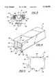
- FIG. 2is a perspective view of a first embodiment of a seat track constructed in accordance with the subject invention
- FIG. 3is a cross sectional view of the assembly of FIG. 2;
- FIG. 4is a perspective view of a second embodiment of a seat track constructed in accordance with the subject invention.
- FIG. 5is an end view of the upper track member of the assembly of FIG. 4;
- FIG. 6is a view similar to FIG. 2 but showing the seat trimmed out
- FIG. 7is a cross sectional view of an alternative channel member of the subject invention.
- the seat assembly 10includes a seat frame 12 defining an occupant sitting area and a back frame 14 defining an occupant back supporting area.
- a headrest 16is supported on the top of the seatback frame 14.
- the frames of the assembly 10include at least one section of the subject invention, and as illustrated that section is the upper rail, generally indicated at 18, of the seat track assembly, which track assembly also includes a lower rail 20 attached to the floor 22 of a vehicle by the brackets 24.
- the upper rail 18is an integral channel having oppositely facing first and second sides 26 and 28.
- the rail section 18is characterized by a retaining wing 30 integral with and extending from and in spaced relationship to the first side 26.
- the wing 30extends to a distal end spaced from the first side 26.
- the upper track section 18is a C-shaped channel as viewed in cross-section with a top 34 extending between the first 26 and 28 second sides and a bottom having a longitudinal slot 36 to define bottom flanges 38 extending inwardly from the lower extremities of the sides 26 and 28 to the edges of the slot 36.
- a tab 40extends outwardly from the first side 26 and forms a co-planar extension of the top wall 34.
- the lower rail 20is slidably disposed and retained in the upper rail 18 by bolts or mounts 42 which extend through the slot 36 in the bottom of the C-shaped upper rail 18, the bolts 42 being supported by the brackets 24.
- a lip 44extends along the distal end of the wing 30 on the side thereof facing the adjacent side 26.
- the lower railhas a generally T-shaped cross section with the top flanges supported on ball bearings 46 which are in rolling engagement with the bottom flanges 38 of the C-shaped channel to define roller elements disposed between the upper and lower rails to facilitate the sliding movement between the rails.
- a bearing cage 48separates the balls along the rails.
- the lower rail 20'is slidably supported within the upper seat supporting rail 18.
- a pair of the channel members 18are spaced from one another on opposite sides of the seat assembly with the tabs 40 extending outwardly from the sides and a suspension 50 extends between the spaced channel members 18.
- a plurality of suspension hooks 52are attached to the suspension 50 on each side and are hooked over the tab 40 of the adjacent channel member 18.
- the suspension 50is one of many well known types, such as a wire net, or the like.
- a foam cushion 54is disposed on the suspension 50 and a trim material 56 covers the cushion 54.
- the trim material 56is attached to the channel member 18 by a plurality of trim hooks 58 attached to the trim 56 and hooked over the wing 30.
- the trimis typically fabric, leather, or the like.
- the hooks 52 and 58are preferably identical for efficiency.
- FIG. 7An alternative embodiment is shown in FIG. 7 wherein the like numerals with an indicate like or corresponding parts to the previous embodiments.
- An assembly as shown in FIG. 7 side 26', 28'includes a recess 60 in each side 26', 28' and a wing 30' extends from each side 26', 28 in the plane of the adjacent side so as to define one wall of the recess 60.
- the channel memberis symmetrical about any transverse axis to include a pair of the recesses 60 and a pair of the wings 30' extend in opposite directions from opposite sides 26' 28' of the channel.
- the channel shown in FIG. 7is most advantageously used as the seat back frame.
Landscapes
- Engineering & Computer Science (AREA)
- Aviation & Aerospace Engineering (AREA)
- Transportation (AREA)
- Mechanical Engineering (AREA)
- Seats For Vehicles (AREA)
Abstract
Description
The subject invention relates to an automotive seat assembly and, more particularly, to the frame of such an assembly.
Conventional seat assemblies for the driver and first passenger for automotive vehicles typically include a seat frame covered with cushions and trim with the frame mounted to the vehicle by a seat track having upper and lower rails for adjusting the fore and aft position of the seat. The seats typically include a suspension for supporting a foam cushion, which is, in turn, covered by trim such as fabric. There is a constant need for improved methods of attaching the suspension systems and/or fabric covers to the seat frame.
A seat assembly of the type utilized in automotive vehicles for supporting an occupant and comprising a seat frame defining an occupant sitting area and a back frame defining an occupant back supporting area. At least a section of one of the frames has oppositely facing first and second sides characterized by a retaining wing integral with and extending from spaced one of the sides.
In accordance with the subject invention, the trim may be simply attached to the seat frame by hooks which attach to the trim and hook over the wing.
Other advantages of the present invention will be readily appreciated as the same becomes better understood by reference to the following detailed description when considered in connection with the accompanying drawings wherein:
FIG. 1 is an environmental view of an automotive seat assembly incorporating the subject invention;
FIG. 2 is a perspective view of a first embodiment of a seat track constructed in accordance with the subject invention;
FIG. 3 is a cross sectional view of the assembly of FIG. 2;
FIG. 4 is a perspective view of a second embodiment of a seat track constructed in accordance with the subject invention;
FIG. 5 is an end view of the upper track member of the assembly of FIG. 4;
FIG. 6 is a view similar to FIG. 2 but showing the seat trimmed out; and
FIG. 7 is a cross sectional view of an alternative channel member of the subject invention.
Referring to the Figures, wherein like numerals reference like or corresponding parts throughout the several views, a seat assembly of the type utilized in automotive vehicles for supporting an occupant is generally shown at 10. The seat assembly 10 includes a seat frame 12 defining an occupant sitting area and a back frame 14 defining an occupant back supporting area. A headrest 16 is supported on the top of the seatback frame 14.
The frames of the assembly 10 include at least one section of the subject invention, and as illustrated that section is the upper rail, generally indicated at 18, of the seat track assembly, which track assembly also includes alower rail 20 attached to the floor 22 of a vehicle by thebrackets 24.
Theupper rail 18 is an integral channel having oppositely facing first andsecond sides rail section 18 is characterized by aretaining wing 30 integral with and extending from and in spaced relationship to thefirst side 26. Thewing 30 extends to a distal end spaced from thefirst side 26.
Theupper track section 18 is a C-shaped channel as viewed in cross-section with atop 34 extending between the first 26 and 28 second sides and a bottom having alongitudinal slot 36 to definebottom flanges 38 extending inwardly from the lower extremities of thesides slot 36. Atab 40 extends outwardly from thefirst side 26 and forms a co-planar extension of thetop wall 34.
Thelower rail 20 is slidably disposed and retained in theupper rail 18 by bolts ormounts 42 which extend through theslot 36 in the bottom of the C-shapedupper rail 18, thebolts 42 being supported by thebrackets 24.
Alip 44 extends along the distal end of thewing 30 on the side thereof facing theadjacent side 26.
In the embodiment of FIGS. 1 through 3, the lower rail has a generally T-shaped cross section with the top flanges supported onball bearings 46 which are in rolling engagement with thebottom flanges 38 of the C-shaped channel to define roller elements disposed between the upper and lower rails to facilitate the sliding movement between the rails. Abearing cage 48 separates the balls along the rails. In the embodiment of FIGS. 4 and 5, the lower rail 20' is slidably supported within the upperseat supporting rail 18.
In accordance with the subject invention, a pair of thechannel members 18 are spaced from one another on opposite sides of the seat assembly with thetabs 40 extending outwardly from the sides and asuspension 50 extends between thespaced channel members 18. A plurality ofsuspension hooks 52 are attached to thesuspension 50 on each side and are hooked over thetab 40 of theadjacent channel member 18. Thesuspension 50 is one of many well known types, such as a wire net, or the like. Afoam cushion 54 is disposed on thesuspension 50 and atrim material 56 covers thecushion 54. Thetrim material 56 is attached to thechannel member 18 by a plurality oftrim hooks 58 attached to thetrim 56 and hooked over thewing 30. The trim is typically fabric, leather, or the like. Thehooks
An alternative embodiment is shown in FIG. 7 wherein the like numerals with an indicate like or corresponding parts to the previous embodiments. An assembly as shown in FIG. 7 side 26', 28' includes arecess 60 in each side 26', 28' and a wing 30' extends from eachside 26', 28 in the plane of the adjacent side so as to define one wall of therecess 60. The channel member is symmetrical about any transverse axis to include a pair of therecesses 60 and a pair of the wings 30' extend in opposite directions from opposite sides 26' 28' of the channel. The channel shown in FIG. 7 is most advantageously used as the seat back frame.
The invention has been described in an illustrative manner, and it is to be understood that the terminology which has been used is intended to be in the nature of words of description rather than of limitation.
Obviously, many modifications and variations of the present invention are possible in light of the above teachings. It is, therefore, to be understood that within the scope of the appended claims, wherein reference numerals are merely for convenience and are not to be in any way limiting, the invention may be practiced otherwise than as specifically described.
Claims (10)
1. A seat assembly of the type utilized in automotive vehicles for supporting an occupant, said assembly comprising:
a seat frame defining an occupant sitting area;
a back frame defining an occupant back supporting area;
at least a section of one of said frames having oppositely facing parallel and symmetrical first and second sides wherein said section is a channel member as viewed in cross-section with a top extending between said first and second sides;
a retaining wing integral with and extending outwardly from said first side to a distal end spaced from said first side;
a tab integral with said top extending outwardly from said first side and forming a linear extension of said top; and including trim material and at least one trim hook attached to said trim material and hooked over said wing.
2. An assembly as set forth in claim 1 including a pair of said channel members spaced from one another on opposite sides of said seat assembly with said tabs extending outwardly from said sides, a suspension extending between said spaced channel members, and at least one suspension hook attached to said suspension on each side and hooked over said tab of the adjacent channel member.
3. An assembly as set forth in claim 2 including mounts secured to said lower rail and extending downwardly for securing said seat assembly to the structure of a vehicle.
4. An assembly as set forth in claim 3 including roller elements disposed between said upper and lower rails to facilitate the sliding movement between said rails.
5. An assembly as set forth in claim 1 wherein said channel defines the upper rail of a seat track, said seat track including a lower rail slidably disposed and retained in said upper rail.
6. An assembly as set forth in claim 1 including a lip extending along said distal end of said wing and on the inward side of said wing toward the adjacent side.
7. An assembly as set forth in claim 1 wherein said first side defines a plane and includes a recess and said wing extends from said first side along the plane of said side and defines one wall of said recess.
8. An assembly as set forth in claim 7 wherein said channel member is symmetrical to include a pair of said recesses and a pair of said wings extending in opposite directions from opposite sides of said channel.
9. A seat assembly of the type utilized in automotive vehicles for supporting an occupant, said assembly comprising:
a seat frame defining an occupant sitting area;
a back frame defining an occupant back supporting area;
at least a section of one of said frames having oppositely facing first and second sides;
a retaining wing integral with and extending from said first side to a distal end spaced from said first side;
said side defining a plane and including a recess, said wing extending from said side along the plane of said side and defining one wall of said recess; and
said section is symmetrical to include a pair of said recesses and a pair of said wings extending in opposite directions from opposite sides of said section.
10. A seat assembly of the type utilized in automotive vehicles for supporting an occupant, said assembly comprising:
a seat frame defining an occupant sitting area;
a back frame defining an occupant back supporting area;
at least one of said frames including a pair of channel members spaced from one another on opposite sides of said seat assembly;
each of said channel members including oppositely facing parallel and symmetrical first and second sides with a top extending between said sides;
a retaining wing integral with and extending outwardly from said first side to a distal end spaced from said side;
a tab integral with said top extending outwardly from said first side and forming a linear extension of said top;
trim material extending between said spaced channel members and having at least one trim hook attached to said trim and hooked over said wing on each channel member; and
a suspension extending between said spaced channel members and having at least one suspension hook attached to said suspension on each side and hooked over said tab of said respective adjacent channel member.
Priority Applications (3)
| Application Number | Priority Date | Filing Date | Title |
|---|---|---|---|
| US08/654,565US5718478A (en) | 1996-05-29 | 1996-05-29 | Integrated attachments-seat frame |
| DE19781805TDE19781805T1 (en) | 1996-05-29 | 1997-05-22 | Seating arrangement |
| PCT/US1997/008789WO1997045289A1 (en) | 1996-05-29 | 1997-05-22 | Integrated attachments-seat frame |
Applications Claiming Priority (1)
| Application Number | Priority Date | Filing Date | Title |
|---|---|---|---|
| US08/654,565US5718478A (en) | 1996-05-29 | 1996-05-29 | Integrated attachments-seat frame |
Publications (1)
| Publication Number | Publication Date |
|---|---|
| US5718478Atrue US5718478A (en) | 1998-02-17 |
Family
ID=24625369
Family Applications (1)
| Application Number | Title | Priority Date | Filing Date |
|---|---|---|---|
| US08/654,565Expired - Fee RelatedUS5718478A (en) | 1996-05-29 | 1996-05-29 | Integrated attachments-seat frame |
Country Status (3)
| Country | Link |
|---|---|
| US (1) | US5718478A (en) |
| DE (1) | DE19781805T1 (en) |
| WO (1) | WO1997045289A1 (en) |
Cited By (32)
| Publication number | Priority date | Publication date | Assignee | Title |
|---|---|---|---|---|
| US5826939A (en)* | 1997-08-13 | 1998-10-27 | Lear Corporation | Method and apparatus for attaching a trim cover to a seat frame |
| US5879051A (en)* | 1996-11-14 | 1999-03-09 | Itw De France | Device and method for fixing a seat covering and the seat obtained |
| US5931538A (en)* | 1996-06-19 | 1999-08-03 | Bertrand Faure Equipements S.A. | Vehicle seat element including a cover tensioned over a metal frame |
| US6000345A (en)* | 1998-01-30 | 1999-12-14 | Gillotti; Michael | Folding table |
| US6189975B1 (en)* | 1998-03-05 | 2001-02-20 | Aisin Seiki Kabushiki Kaisha | Seat frame assembly |
| US6220661B1 (en) | 1999-04-19 | 2001-04-24 | Steelcase Development Inc. | Chair back and method of assembly |
| US6406093B1 (en)* | 2000-03-29 | 2002-06-18 | Lear Corporation | Attachment for seat assembly |
| US20020125759A1 (en)* | 1999-04-19 | 2002-09-12 | Peterson Gordon J. | Method of manufacturing cushion construction for seating unit |
| US6585321B1 (en)* | 2000-11-28 | 2003-07-01 | Tachi-S Co., Ltd. | Seat adjuster for vehicle seat |
| US20030151294A1 (en)* | 2002-02-13 | 2003-08-14 | Glater Irving W. | Interchangeable seat cushions for automotive bucket seats |
| US6616230B2 (en)* | 2001-01-31 | 2003-09-09 | Johnson Controls Automotive Systems Corporation | Slidable vehicle seat assembly |
| US20040155511A1 (en)* | 2003-01-15 | 2004-08-12 | Euromotive Gmbh And Co. Kg | Rear seat back for a vehicle back seat |
| US20050215663A1 (en)* | 2004-01-21 | 2005-09-29 | Berge Charles T | Inkjet inks containing crosslinked polyurethanes |
| US20070011853A1 (en)* | 2005-07-13 | 2007-01-18 | Smith Lyle J | System for attaching trim covers to a flexible substrate |
| FR2898859A1 (en)* | 2006-03-21 | 2007-09-28 | Faurecia Sieges Automobile | Seat element e.g. seat base, trimming method for motor vehicle, involves exerting pressure on seat element trim in direction of trimming towards armature for engaging fixation element e.g. clip, on armature |
| US20080258523A1 (en)* | 2007-04-19 | 2008-10-23 | Hope Global, Division Of Nfa Corp. | Festooned trim clip system and method for attaching festooned clips to a substrate |
| US20090064471A1 (en)* | 2007-09-07 | 2009-03-12 | Hope Global, Division Of Nfa Corp. | Low-profile upholstery clip for attaching a bead to a foam substrate |
| US20090121535A1 (en)* | 2006-05-10 | 2009-05-14 | Johnson Control Technology Company | Structural element for vehicle seat |
| US20100148551A1 (en)* | 2008-12-11 | 2010-06-17 | Ykk Corporation Of America | Soft cover for covering a seat |
| US20110049948A1 (en)* | 2009-08-27 | 2011-03-03 | Lear Corporation | Seat assembly having a trim cover |
| US20120133193A1 (en)* | 2010-11-30 | 2012-05-31 | Toyota Boshoku Kabushiki Kaisha | Vehicle seat |
| US20130062918A1 (en)* | 2011-09-08 | 2013-03-14 | Eleven International Co., Ltd | Seat cover and cover attaching tool |
| USD689319S1 (en) | 2012-09-20 | 2013-09-10 | Steelcase Inc. | Chair |
| JP2014223236A (en)* | 2013-05-17 | 2014-12-04 | スズキ株式会社 | Seat cushion |
| USD758774S1 (en) | 2015-04-24 | 2016-06-14 | Steelcase Inc. | Headrest assembly |
| USD759415S1 (en) | 2015-04-24 | 2016-06-21 | Steelcase Inc. | Headrest |
| USD760526S1 (en) | 2015-04-24 | 2016-07-05 | Steelcase Inc. | Headrest assembly |
| US9446698B2 (en)* | 2014-04-25 | 2016-09-20 | Toyota Boshoku Kabushiki Kaisha | Vehicle seat |
| USD781605S1 (en) | 2015-04-24 | 2017-03-21 | Steelcase Inc. | Chair |
| USD781604S1 (en) | 2015-04-24 | 2017-03-21 | Steelcase Inc. | Chair |
| JPWO2015105000A1 (en)* | 2014-01-07 | 2017-03-23 | 株式会社タチエス | Vehicle seat |
| US9834431B2 (en) | 2015-08-28 | 2017-12-05 | Hope Global, Division Of Nfa Corp. | Listing bead for upholstery clips |
Families Citing this family (1)
| Publication number | Priority date | Publication date | Assignee | Title |
|---|---|---|---|---|
| US8459605B2 (en) | 2006-11-15 | 2013-06-11 | Johnson Controls Technology Company | Rail system and vehicle seat |
Citations (9)
| Publication number | Priority date | Publication date | Assignee | Title |
|---|---|---|---|---|
| US3685872A (en)* | 1969-11-19 | 1972-08-22 | Cox Of Watford Ltd | Slide for a vehicle seat |
| US3930632A (en)* | 1972-12-27 | 1976-01-06 | Nissan Motor Company Limited | Adjustable seat assembly |
| US4492408A (en)* | 1982-01-19 | 1985-01-08 | Allen Industries, Inc. | Vehicle seat construction and method of making the same |
| US4666209A (en)* | 1981-07-28 | 1987-05-19 | Aisin Seiki Kabushiki Kaisha | Seat assembly for vehicles |
| US4720073A (en)* | 1984-07-25 | 1988-01-19 | Brose Fahrzeugteile Gmbh & Co. Kg. | Seat longitudinal adjusting mechanism |
| US4828214A (en)* | 1988-02-16 | 1989-05-09 | Tachi-S Company Limited | Slide rail device for vehicle seat |
| US4948189A (en)* | 1988-03-24 | 1990-08-14 | Aisin Seiki Kabushiki Kaisha | Seat slide assembly |
| US5188329A (en)* | 1991-10-23 | 1993-02-23 | Tachi-S Co. Ltd. | Structure for covering slide railing seat adjuster |
| US5439271A (en)* | 1993-11-08 | 1995-08-08 | Hoover Universal, Inc. | Vehicle seat with extruded frame members |
Family Cites Families (4)
| Publication number | Priority date | Publication date | Assignee | Title |
|---|---|---|---|---|
| FR1530540A (en)* | 1967-05-16 | 1968-06-28 | Mecanismes Comp Ind De | Backstage seat improvements |
| JPS61295143A (en)* | 1985-06-24 | 1986-12-25 | Tachi S Co Ltd | seat frame |
| EP0607489A1 (en)* | 1993-01-22 | 1994-07-27 | Ignaz Vogel GmbH & Co KG, Fahrzeugsitze | Fast covering |
| IT1266193B1 (en)* | 1994-08-04 | 1996-12-23 | Ferrero Guilio Spa | SLIDE-GUIDE ASSEMBLY, PARTICULARLY FOR VEHICLE SEATS. |
- 1996
- 1996-05-29USUS08/654,565patent/US5718478A/ennot_activeExpired - Fee Related
- 1997
- 1997-05-22WOPCT/US1997/008789patent/WO1997045289A1/enactiveApplication Filing
- 1997-05-22DEDE19781805Tpatent/DE19781805T1/ennot_activeWithdrawn
Patent Citations (9)
| Publication number | Priority date | Publication date | Assignee | Title |
|---|---|---|---|---|
| US3685872A (en)* | 1969-11-19 | 1972-08-22 | Cox Of Watford Ltd | Slide for a vehicle seat |
| US3930632A (en)* | 1972-12-27 | 1976-01-06 | Nissan Motor Company Limited | Adjustable seat assembly |
| US4666209A (en)* | 1981-07-28 | 1987-05-19 | Aisin Seiki Kabushiki Kaisha | Seat assembly for vehicles |
| US4492408A (en)* | 1982-01-19 | 1985-01-08 | Allen Industries, Inc. | Vehicle seat construction and method of making the same |
| US4720073A (en)* | 1984-07-25 | 1988-01-19 | Brose Fahrzeugteile Gmbh & Co. Kg. | Seat longitudinal adjusting mechanism |
| US4828214A (en)* | 1988-02-16 | 1989-05-09 | Tachi-S Company Limited | Slide rail device for vehicle seat |
| US4948189A (en)* | 1988-03-24 | 1990-08-14 | Aisin Seiki Kabushiki Kaisha | Seat slide assembly |
| US5188329A (en)* | 1991-10-23 | 1993-02-23 | Tachi-S Co. Ltd. | Structure for covering slide railing seat adjuster |
| US5439271A (en)* | 1993-11-08 | 1995-08-08 | Hoover Universal, Inc. | Vehicle seat with extruded frame members |
Cited By (50)
| Publication number | Priority date | Publication date | Assignee | Title |
|---|---|---|---|---|
| US5931538A (en)* | 1996-06-19 | 1999-08-03 | Bertrand Faure Equipements S.A. | Vehicle seat element including a cover tensioned over a metal frame |
| US5879051A (en)* | 1996-11-14 | 1999-03-09 | Itw De France | Device and method for fixing a seat covering and the seat obtained |
| US5826939A (en)* | 1997-08-13 | 1998-10-27 | Lear Corporation | Method and apparatus for attaching a trim cover to a seat frame |
| US6000345A (en)* | 1998-01-30 | 1999-12-14 | Gillotti; Michael | Folding table |
| US6375268B2 (en) | 1998-03-05 | 2002-04-23 | Aisin Seiki Kabushiki Kaisha | Seat frame assembly |
| US6189975B1 (en)* | 1998-03-05 | 2001-02-20 | Aisin Seiki Kabushiki Kaisha | Seat frame assembly |
| US6220661B1 (en) | 1999-04-19 | 2001-04-24 | Steelcase Development Inc. | Chair back and method of assembly |
| US6880215B2 (en)* | 1999-04-19 | 2005-04-19 | Steelcase Development Corporation | Method of manufacturing cushion construction for seating unit |
| US20020125759A1 (en)* | 1999-04-19 | 2002-09-12 | Peterson Gordon J. | Method of manufacturing cushion construction for seating unit |
| US6508509B2 (en) | 1999-04-19 | 2003-01-21 | Steelcase Development Corporation | Back for seating unit and method of assembly |
| US7216936B2 (en) | 1999-04-19 | 2007-05-15 | Steelcase Development Corporation | Cushion construction for seating unit |
| US20050206212A1 (en)* | 1999-04-19 | 2005-09-22 | Peterson Gordon J | Cushion construction for seating unit |
| US6406093B1 (en)* | 2000-03-29 | 2002-06-18 | Lear Corporation | Attachment for seat assembly |
| US6585321B1 (en)* | 2000-11-28 | 2003-07-01 | Tachi-S Co., Ltd. | Seat adjuster for vehicle seat |
| US6616230B2 (en)* | 2001-01-31 | 2003-09-09 | Johnson Controls Automotive Systems Corporation | Slidable vehicle seat assembly |
| US20030151294A1 (en)* | 2002-02-13 | 2003-08-14 | Glater Irving W. | Interchangeable seat cushions for automotive bucket seats |
| US20040155511A1 (en)* | 2003-01-15 | 2004-08-12 | Euromotive Gmbh And Co. Kg | Rear seat back for a vehicle back seat |
| US6981748B2 (en)* | 2003-01-15 | 2006-01-03 | Euromotive Gmbh & Co. Kg | Rear seat back for a vehicle back seat |
| US20050215663A1 (en)* | 2004-01-21 | 2005-09-29 | Berge Charles T | Inkjet inks containing crosslinked polyurethanes |
| US20070011853A1 (en)* | 2005-07-13 | 2007-01-18 | Smith Lyle J | System for attaching trim covers to a flexible substrate |
| US7752720B2 (en) | 2005-07-13 | 2010-07-13 | Smith Lyle J | System for attaching trim covers to a flexible substrate |
| US7487575B2 (en) | 2005-07-13 | 2009-02-10 | Lyle J Smith | System for attaching trim covers to a flexible substrate |
| US20090165263A1 (en)* | 2005-07-13 | 2009-07-02 | Smith Lyle J | System for attaching trim covers to a flexible substrate |
| FR2898859A1 (en)* | 2006-03-21 | 2007-09-28 | Faurecia Sieges Automobile | Seat element e.g. seat base, trimming method for motor vehicle, involves exerting pressure on seat element trim in direction of trimming towards armature for engaging fixation element e.g. clip, on armature |
| US20090121535A1 (en)* | 2006-05-10 | 2009-05-14 | Johnson Control Technology Company | Structural element for vehicle seat |
| US7905550B2 (en)* | 2006-05-10 | 2011-03-15 | Johnson Controls Technology Company | Structural element for vehicle seat |
| US20080258523A1 (en)* | 2007-04-19 | 2008-10-23 | Hope Global, Division Of Nfa Corp. | Festooned trim clip system and method for attaching festooned clips to a substrate |
| US8091184B2 (en) | 2007-04-19 | 2012-01-10 | Hope Global, Division Of Nfa Corp. | Festooned trim clip system and method for attaching festooned clips to a substrate |
| US20090064471A1 (en)* | 2007-09-07 | 2009-03-12 | Hope Global, Division Of Nfa Corp. | Low-profile upholstery clip for attaching a bead to a foam substrate |
| US8099837B2 (en) | 2007-09-07 | 2012-01-24 | Hope Global, Division Of Nfa Corporation | Low-profile upholstery clip for attaching a bead to a foam substrate |
| US20100148551A1 (en)* | 2008-12-11 | 2010-06-17 | Ykk Corporation Of America | Soft cover for covering a seat |
| US7857383B2 (en)* | 2008-12-11 | 2010-12-28 | Ykk Corporation | Soft cover for covering a seat |
| US20110049948A1 (en)* | 2009-08-27 | 2011-03-03 | Lear Corporation | Seat assembly having a trim cover |
| US8240759B2 (en)* | 2009-08-27 | 2012-08-14 | Lear Corporation | Seat assembly having a trim cover |
| US20120133193A1 (en)* | 2010-11-30 | 2012-05-31 | Toyota Boshoku Kabushiki Kaisha | Vehicle seat |
| US20130062918A1 (en)* | 2011-09-08 | 2013-03-14 | Eleven International Co., Ltd | Seat cover and cover attaching tool |
| US8979195B2 (en)* | 2011-09-08 | 2015-03-17 | Eleven International Co., Ltd. | Seat cover and cover attaching tool |
| USD690547S1 (en) | 2012-09-20 | 2013-10-01 | Steelcase Inc. | Chair |
| USD699959S1 (en) | 2012-09-20 | 2014-02-25 | Steelcase Inc. | Chair |
| USD689319S1 (en) | 2012-09-20 | 2013-09-10 | Steelcase Inc. | Chair |
| JP2014223236A (en)* | 2013-05-17 | 2014-12-04 | スズキ株式会社 | Seat cushion |
| JPWO2015105000A1 (en)* | 2014-01-07 | 2017-03-23 | 株式会社タチエス | Vehicle seat |
| US9446698B2 (en)* | 2014-04-25 | 2016-09-20 | Toyota Boshoku Kabushiki Kaisha | Vehicle seat |
| USD758774S1 (en) | 2015-04-24 | 2016-06-14 | Steelcase Inc. | Headrest assembly |
| USD759415S1 (en) | 2015-04-24 | 2016-06-21 | Steelcase Inc. | Headrest |
| USD760526S1 (en) | 2015-04-24 | 2016-07-05 | Steelcase Inc. | Headrest assembly |
| USD781605S1 (en) | 2015-04-24 | 2017-03-21 | Steelcase Inc. | Chair |
| USD781604S1 (en) | 2015-04-24 | 2017-03-21 | Steelcase Inc. | Chair |
| US9834431B2 (en) | 2015-08-28 | 2017-12-05 | Hope Global, Division Of Nfa Corp. | Listing bead for upholstery clips |
| US10508019B2 (en) | 2015-08-28 | 2019-12-17 | Hope Global, Division Of Nfa Corp. | Listing bead for upholstery clips |
Also Published As
| Publication number | Publication date |
|---|---|
| DE19781805T1 (en) | 1999-07-15 |
| WO1997045289A1 (en) | 1997-12-04 |
Similar Documents
| Publication | Publication Date | Title |
|---|---|---|
| US5718478A (en) | Integrated attachments-seat frame | |
| US6672666B2 (en) | Mesh seat with displaceable bolsters | |
| US5213300A (en) | Extruded automotive seat track | |
| US9849817B2 (en) | Composite seat structure | |
| US6672662B1 (en) | Vehicle seat | |
| US5527084A (en) | Collapsible arm rest, door interior trim panel and arm rest support assembly | |
| US5246270A (en) | Passenger seat arrangement | |
| US10442326B2 (en) | Seating assembly with suspension | |
| EP0175110B1 (en) | Integral seat frame and track | |
| EP0590237A1 (en) | Automotive seat having integrally mounted seat belt assembly | |
| US4969687A (en) | Passenger seat for motor vehicle | |
| US6065795A (en) | Seating arrangement for a motor vehicle | |
| CA1227116A (en) | Lightweight seat frame for vehicles | |
| US9802515B2 (en) | Vehicle seat strap retaining assembly | |
| US20080100113A1 (en) | Power seat motor mounting assembly | |
| US10513204B2 (en) | Seating assembly pivot bracket | |
| US6036253A (en) | Light weight seat track assembly | |
| US5645318A (en) | Seat back support connection | |
| US9963052B2 (en) | Seat system | |
| EP2154018B1 (en) | Vehicle seat | |
| JPH0539944Y2 (en) | ||
| US9802516B2 (en) | Vehicle seat strap retaining assembly | |
| DE102008061973A1 (en) | Vehicle seat, has cushion carrier comprising module-like base body that is made from profile units, and ramp designed as contour section that is manufactured from hard foam unit, where foam unit is supported on base body in sections | |
| EP0665141A1 (en) | Front seat arrangement for light trucks, vans or the like | |
| JPS58112833A (en) | Automobile seat adjuster |
Legal Events
| Date | Code | Title | Description |
|---|---|---|---|
| AS | Assignment | Owner name:LEAR CORPORATION, MICHIGAN Free format text:ASSIGNMENT OF ASSIGNORS INTEREST;ASSIGNOR:ALLISON, GREGORY;REEL/FRAME:008036/0803 Effective date:19960528 | |
| FEPP | Fee payment procedure | Free format text:PAYOR NUMBER ASSIGNED (ORIGINAL EVENT CODE: ASPN); ENTITY STATUS OF PATENT OWNER: LARGE ENTITY | |
| REMI | Maintenance fee reminder mailed | ||
| LAPS | Lapse for failure to pay maintenance fees | ||
| STCH | Information on status: patent discontinuation | Free format text:PATENT EXPIRED DUE TO NONPAYMENT OF MAINTENANCE FEES UNDER 37 CFR 1.362 | |
| FP | Lapsed due to failure to pay maintenance fee | Effective date:20020217 |