US5718442A - Power wheelchair with extended power seat frame tilt - Google Patents
Power wheelchair with extended power seat frame tiltDownload PDFInfo
- Publication number
- US5718442A US5718442AUS08/579,150US57915095AUS5718442AUS 5718442 AUS5718442 AUS 5718442AUS 57915095 AUS57915095 AUS 57915095AUS 5718442 AUS5718442 AUS 5718442A
- Authority
- US
- United States
- Prior art keywords
- seat frame
- cross member
- frame
- base frame
- seat
- Prior art date
- Legal status (The legal status is an assumption and is not a legal conclusion. Google has not performed a legal analysis and makes no representation as to the accuracy of the status listed.)
- Expired - Fee Related
Links
- 239000000725suspensionSubstances0.000claimsdescription36
- 238000000034methodMethods0.000claimsdescription9
- 230000013011matingEffects0.000claimsdescription6
- 230000000295complement effectEffects0.000claimsdescription2
- 230000008878couplingEffects0.000claims3
- 238000010168coupling processMethods0.000claims3
- 238000005859coupling reactionMethods0.000claims3
- 238000010009beatingMethods0.000claims1
- 230000001419dependent effectEffects0.000description3
- 210000005069earsAnatomy0.000description2
- 208000027418Wounds and injuryDiseases0.000description1
- 238000009825accumulationMethods0.000description1
- 230000003213activating effectEffects0.000description1
- 230000006378damageEffects0.000description1
- 238000010586diagramMethods0.000description1
- 201000010099diseaseDiseases0.000description1
- 208000037265diseases, disorders, signs and symptomsDiseases0.000description1
- 238000005553drillingMethods0.000description1
- 208000014674injuryDiseases0.000description1
- 238000009434installationMethods0.000description1
- 238000004519manufacturing processMethods0.000description1
- 238000012986modificationMethods0.000description1
- 230000004048modificationEffects0.000description1
- 230000008450motivationEffects0.000description1
- 230000002459sustained effectEffects0.000description1
- 239000002699waste materialSubstances0.000description1
Images


Classifications
- A—HUMAN NECESSITIES
- A61—MEDICAL OR VETERINARY SCIENCE; HYGIENE
- A61G—TRANSPORT, PERSONAL CONVEYANCES, OR ACCOMMODATION SPECIALLY ADAPTED FOR PATIENTS OR DISABLED PERSONS; OPERATING TABLES OR CHAIRS; CHAIRS FOR DENTISTRY; FUNERAL DEVICES
- A61G5/00—Chairs or personal conveyances specially adapted for patients or disabled persons, e.g. wheelchairs
- A61G5/10—Parts, details or accessories
- A61G5/1056—Arrangements for adjusting the seat
- A61G5/1075—Arrangements for adjusting the seat tilting the whole seat backwards
- A—HUMAN NECESSITIES
- A61—MEDICAL OR VETERINARY SCIENCE; HYGIENE
- A61G—TRANSPORT, PERSONAL CONVEYANCES, OR ACCOMMODATION SPECIALLY ADAPTED FOR PATIENTS OR DISABLED PERSONS; OPERATING TABLES OR CHAIRS; CHAIRS FOR DENTISTRY; FUNERAL DEVICES
- A61G5/00—Chairs or personal conveyances specially adapted for patients or disabled persons, e.g. wheelchairs
- A61G5/10—Parts, details or accessories
- A61G5/1081—Parts, details or accessories with shock absorbers or other suspension arrangements between frame and seat
- A—HUMAN NECESSITIES
- A61—MEDICAL OR VETERINARY SCIENCE; HYGIENE
- A61G—TRANSPORT, PERSONAL CONVEYANCES, OR ACCOMMODATION SPECIALLY ADAPTED FOR PATIENTS OR DISABLED PERSONS; OPERATING TABLES OR CHAIRS; CHAIRS FOR DENTISTRY; FUNERAL DEVICES
- A61G5/00—Chairs or personal conveyances specially adapted for patients or disabled persons, e.g. wheelchairs
- A61G5/10—Parts, details or accessories
- A61G5/1056—Arrangements for adjusting the seat
- A61G5/107—Arrangements for adjusting the seat positioning the whole seat forward or rearward
- A—HUMAN NECESSITIES
- A61—MEDICAL OR VETERINARY SCIENCE; HYGIENE
- A61G—TRANSPORT, PERSONAL CONVEYANCES, OR ACCOMMODATION SPECIALLY ADAPTED FOR PATIENTS OR DISABLED PERSONS; OPERATING TABLES OR CHAIRS; CHAIRS FOR DENTISTRY; FUNERAL DEVICES
- A61G5/00—Chairs or personal conveyances specially adapted for patients or disabled persons, e.g. wheelchairs
- A61G5/10—Parts, details or accessories
- A61G5/12—Rests specially adapted therefor, e.g. for the head or the feet
Definitions
- This inventionrelates in general to power wheelchairs and more particularly to such wheelchairs having extended power seat frame tilt capabilities.
- a conventional battery-powered wheelchairfor example, Invacare Ranger X Storm Series (Model & Trademarks of Invacare Corp.), has a framework including a fixed suspension.
- the frameworkcomprises a base frame having horizontally arranged, spaced-apart, side square tubes and a front cross member. Over the base frame is suspended a cylindrical tubular seat frame which is made up of side members and of front and rear cross members.
- This seat framesupports a dismountable seat structure which includes a seat pan that supports a seat, armrests, a back, footrests and sometimes a headrest.
- the dealerBefore delivering the power wheelchair to the end user, the dealer can preadjust the seat frame's tilt within a limited range, typically it is adjusted to about 5°.
- the above described power wheelchairis all they desire or can afford.
- the wheelchairmay become uncomfortable for lack of extended power seat tilting. Such tilting may become needed following a sustained injury or disease, or for purely personal rather than clinical reasons.
- the prior artcould provide power seat frame tilting only by (1) removing the seat structure together with the seat frame on which it is mounted, and (2) by replacing it with a new seat structure together with a new seat frame that can become attached to the original manufacturer's framework by bolts driven through the already existing holes therein.
- the dealerBefore delivering a power wheelchair to the user, the dealer can remove the existing suspension and install the new kit on the existing framework using only existing holes therein.
- the original seat frameis modified and the seat structure thereon is utilized, thereby avoiding unnecessary and very costly waste.
- the new suspensionuses support/pivot means on the base frame and complementary pivot means on a structural member of the original seat frame.
- the lower end of a power actuatorcan be mounted on a lower bracket coupled to the front cross member of the base frame, and its upper end can be mounted on an upper bracket coupled to the front cross member of the seat frame.
- the novel kit of this inventionincludes pivot means for converting the fixed rear end suspension into a pivotable rear end suspension.
- the kitprovides left and right side pivots for use on an existing rear cross member of the seat frame so that the selected cross member can serve as a pivot axle for the seat frame and rotate on a pair of rear support/bearing blocks mounted over the base frame's side members.
- the existing electronic control moduleis mounted on the lower bracket underneath the seat frame.
- the actuatorWhen the actuator receives power from the existing wheelchair's battery through the kits' control toggle switch, it extends/contracts its shaft in steps, thereby applying tilting forces to the front end of the seat frame which cause it to pivot in opposite angular directions relative to the stationary base frame.
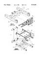
- FIGS. 1 and 2are exploded views of a typical prior art power wheelchair framework and its suspension showing the base frame, the seat frame, and the electronic module;
- FIG. 3is an exploded view of the parts which make up the kit of this invention, with the parts being shown in position for installation on the existing framework shown in FIGS. 1 and 2.
- the kit's partsare installed using existing holes on the framework.
- the existing seat frame in modified formis utilized in the new process of providing the desired extended power seat tilting;
- FIG. 4is a perspective view of the novel wheelchair whose framework is shown in FIGS. 1 and 2 but which is modified to incorporate the kit of this invention, thereby providing the desired wheelchair with extended power seat frame tilting;
- FIG. 5is a schematic electric circuit diagram of the connections between the actuator, the toggle switch, and the existing power source on the wheelchair.
- FIGS. 1 and 2show a power wheelchair framework, generally designated as 8, such as is included in a popular power wheelchair sold by Invacare Corporation under its model/trademark Ranger X Storm Series.
- Framework 8includes a base frame 10 (FIG. 1) having horizontally-arranged, spaced-apart, square tubular side frame members 12,12' having holes 13, a front tubular cross member 14 having one pair of spaced apart holes 15 for removably accepting the bolts that secure an electronic control module 16 to cross member 14, and another pair of spaced apart holes 15'.
- Framework 8has a suspension, generally designated as 9 (FIG. 2), that suspends over base frame 10 a seat frame, generally-designated as 20, that supports a dismountable seat structure shown in FIG. 4, which includes a seat pan that supports a cushion seat, armrests, a back, and footrests.
- a suspensiongenerally designated as 9 (FIG. 2), that suspends over base frame 10 a seat frame, generally-designated as 20, that supports a dismountable seat structure shown in FIG. 4, which includes a seat pan that supports a cushion seat, armrests, a back, and footrests.
- Seat frame 20is made up of horizontally-arranged, spaced-apart, cylindrical side members 22,22', which are linked to a cylindrical front cross member 24 having holes 25, and to a cylindrical rear cross cylindrical member 26 having a dependent cross member 26', which has at each end thereof a plastic plug 29 to prevent moisture accumulation therein, and which carries a pair of horizontally spaced ears or tabs 28.
- a pair of rear seat support brackets 30,30'are bolted to the rear ends of base frame's side members 12,12' through holes 13. Ears 28 become pivotably connected to rear brackets 30,30', respectively.
- a pair of front seat support brackets 32,32'are bolted, through the spaced apart holes 15', to the base frame's cross member 14. Brackets 32,32' have vertically spaced height adjustment holes 33.
- the lower ends of a pair of links 34are removably and adjustably received within holes 33 in seat brackets 32,32'.
- the upper ends of links 34are bolted to seat frame's front cross member 24 through its spaced-apart holes 25.
- the angle of seat frame tiltingis preadjusted by the manufacturer or its dealer by raising or lowering both links 34 within their mating front support bracket 32,32' together with their connecting pins that extend through the vertically spaced-holes 33.
- the standard preadjustment fixed tilt angle for seat frame 20is about 5° which makes the standard seat to floor dimension about 17.5 inches.
- rear seat brackets 30,30', front seat brackets 32,32', rear cross member 26 and its dependent cross member 26', and adjustment links 34together form the existing seat suspension 9 which fixedly suspends seat frame 20 over base frame 10.
- this inventionprovides a new suspension 36 (FIG. 3) for the existing wheelchair's framework 8 (FIGS. 1, 2).
- This new suspension 36replaces the original suspension 9, which is limited to providing only a fixed support for seat frame 20.
- the new suspension 36offers a tiltable pivotal support to seat frame 20 by using an existing structural member of seat frame 20.
- this existing membercan be rear cylindrical cross member 26 or its dependent cylindrical cross member 26'.
- the new suspension 36also uses a novel kit 40 which includes pivot means 41 for use with rear cross member 26 (FIG. 3) so that the pivot means 41 and cross member 26 together form a pivot axle PA for seat frame 20 to rotate about on a pair of rear support/bearing blocks 42,42' mounted over the base frame's side members 12,12'.
- a power actuator 50can be mounted between a lower bracket 46 and an upper bracket 48 to provide extended power seat frame tilting (FIGS. 3, 4, 5) to the standard power wheelchair, without replacing the manufacturer's seat frame 20, as is presently the prevailing practice.
- the novel kit 40also includes a toggle switch 54 (FIG. 5), a power supply harness 52, and bottom seat frame stops 56.
- kit 40requires first disconnecting from framework 8 (FIGS. 1, 2) the seat frame's existing suspension 9 and other parts that may be attached to either base frame 10 and/or seat frame 20.
- Removing seat frame suspension 9involves disconnecting
- rear seat support brackets 30,30'from base frame's side members 12,12' and from pivot lugs 28 on rear seat cross member 26',
- the novel suspension 36includes: cross member 26 (FIGS. 3-4) having a pivot 41 at each end thereof, support/bearing blocks 42,42' bolted to the rear ends of base frame's side members 12,12' through holes 13, each block carrying on its inner face a self-lubricating bearing 44 in which is journaled a pivot 41, lower actuator bracket 46 connected to the front face of base frame's cross member 14 through holes 15', and upper actuator bracket 48 connected to the rear face of seat frame's front cross member 24 through holes 25.
- cross member 26Since cross member 26 has a pivot 41 at each end thereof, it serves as pivot axle for seat frame 20 to rotate in opposite angular directions relative to stationary base frame 10 about pivot axis PA extending through both pivots 41.
- Actuator 50(FIGS. 3-5) is preferably a 24-volt DC, ball bearing, screw actuator available from Rayco International Corp. It is controlled by high-amp toggle switch 54 to provide a continuously adjustable seat frame tilt as the actuator's shaft 51 linearly moves in steps.
- actuator 50Because the lower end of actuator 50 is pivotably connected to mount tabs 58 on lower bracket 46 and its upper end is pivotably connected to mount tabs 59 on upper bracket 48, it can be easily installed or removed for repair without disturbing the wheelchair's framework.
- electronic control module 16can be connected to tabs 60 on lower bracket 46 underneath seat frame 20. In one embodiment, to so position electronic module 16 resulted in an increase of the seat to ground distance from 17.5" to 19.5".
- the kit's harness 52interconnects battery 53, toggle switch 54 and the motor of actuator 50.
- this inventionalso provides a novel wheelchair 62 which incorporates the novel suspension 36.
- the seat frame 20is shown to support a conventional, dismountable seat structure 64 that includes a seat pan 66 supporting a seat 68, armrests 70, a back 72, and footrests 74.
- the wheelchair 62also has the usual joystick 76, rear wheels 78 and front caster wheels 80.
- the toggle switch 54is conveniently mounted next to joystick 76 or it can be incorporated therewithin.
- the inventionprovides to the user of an existing power wheelchair the option of obtaining extended power seat frame tilting, which is relatively inexpensive primarily because the seat frame and the seat structure thereon that originally came with the new power wheelchair are utilized.
- This optioncan be obtained from using the novel kit 40.
- the dealercan easily remove the existing suspension and install the new kit on the existing framework.
- the original seat frameis slightly modified without affecting the utility assigned to it by the manufacturer.
- the kititself is relatively simple, practical, compact, light weight, strong, and very easy to install using only existing holes on the wheelchair's framework.
- each pivot 41could extend inwardly from each inner side of rear mounting blocks 42,42', and each end of rear cross member 26 could accept a bearing therein for supporting its mating and opposite pivot 41.
Landscapes
- Health & Medical Sciences (AREA)
- Life Sciences & Earth Sciences (AREA)
- Animal Behavior & Ethology (AREA)
- General Health & Medical Sciences (AREA)
- Public Health (AREA)
- Veterinary Medicine (AREA)
- Carriages For Children, Sleds, And Other Hand-Operated Vehicles (AREA)
Abstract
Description
Claims (16)
Priority Applications (1)
| Application Number | Priority Date | Filing Date | Title |
|---|---|---|---|
| US08/579,150US5718442A (en) | 1995-12-27 | 1995-12-27 | Power wheelchair with extended power seat frame tilt |
Applications Claiming Priority (1)
| Application Number | Priority Date | Filing Date | Title |
|---|---|---|---|
| US08/579,150US5718442A (en) | 1995-12-27 | 1995-12-27 | Power wheelchair with extended power seat frame tilt |
Publications (1)
| Publication Number | Publication Date |
|---|---|
| US5718442Atrue US5718442A (en) | 1998-02-17 |
Family
ID=24315764
Family Applications (1)
| Application Number | Title | Priority Date | Filing Date |
|---|---|---|---|
| US08/579,150Expired - Fee RelatedUS5718442A (en) | 1995-12-27 | 1995-12-27 | Power wheelchair with extended power seat frame tilt |
Country Status (1)
| Country | Link |
|---|---|
| US (1) | US5718442A (en) |
Cited By (28)
| Publication number | Priority date | Publication date | Assignee | Title |
|---|---|---|---|---|
| US5884935A (en)* | 1997-06-09 | 1999-03-23 | Tholkes; Alan L. | Modular standing support |
| US5957474A (en)* | 1997-02-24 | 1999-09-28 | Pdg Inc. | Wheelchair for large individuals |
| US5964473A (en)* | 1994-11-18 | 1999-10-12 | Degonda-Rehab S.A. | Wheelchair for transporting or assisting the displacement of at least one user, particularly for handicapped person |
| US6154690A (en)* | 1999-10-08 | 2000-11-28 | Coleman; Raquel | Multi-feature automated wheelchair |
| US6257609B1 (en)* | 1998-03-27 | 2001-07-10 | O'neill, Sr. Theodore C. | Tilt-in-space wheelchair |
| US6409265B1 (en) | 2000-05-31 | 2002-06-25 | Sunrise Medical Hhg, Inc. | Tilting and reclining wheelchair |
| US6419253B1 (en)* | 2000-05-01 | 2002-07-16 | Invacare Corporation | Wheelchair having a double turnbuckle height adjustment |
| US6450518B1 (en) | 1999-05-28 | 2002-09-17 | Jerald R. Howard | Wheelchair |
| US6588792B1 (en)* | 2000-05-31 | 2003-07-08 | Sunrise Medical Hhg Inc. | Method of programming and operating tilt and recline functions in a wheelchair |
| US6611975B1 (en)* | 2001-02-23 | 2003-09-02 | Roy D. Ricketts | Motorized bed assembly |
| US6715784B2 (en) | 2000-05-31 | 2004-04-06 | Sunrise Medical Hhg Inc. | Method programming and operating a wheelchair having tilt and recline functions |
| US20050046129A1 (en)* | 2003-08-15 | 2005-03-03 | Antonishak Stephen J. | Constant center of gravity lift and tilt mechanisms for a wheelchair seat |
| US6979010B1 (en)* | 2004-06-01 | 2005-12-27 | Kwapis Randal J | Sport utility wheelchair |
| US20060076747A1 (en)* | 2004-10-08 | 2006-04-13 | Sunrise Medical Hhg Inc. | Wheelchair suspension system |
| US20060087097A1 (en)* | 2004-08-16 | 2006-04-27 | Kramer Kenneth L | Home care equipment system |
| EP1721592A3 (en)* | 2005-05-14 | 2006-11-22 | Specialised Orthotic Services Limited | Wheelchairs |
| US20070050096A1 (en)* | 2005-08-31 | 2007-03-01 | Invacare Corporation | Programmable actuator controller for power positioning seat or leg support of a wheelchair |
| US20070055424A1 (en)* | 2005-08-31 | 2007-03-08 | Darryl Peters | Method and apparatus for setting or modifying programmable parameter in power driven wheelchair |
| US20070074917A1 (en)* | 2005-08-31 | 2007-04-05 | Invacare Corp. | Adjustable mount for controller of power driven wheelchair |
| US20070085301A1 (en)* | 2005-10-18 | 2007-04-19 | Watkins Mervyn M | Center-of-gravity tilt-in-space wheelchair |
| US20090186747A1 (en)* | 2008-01-22 | 2009-07-23 | Invacare Corporation | Seat |
| US20100007180A1 (en)* | 2008-07-08 | 2010-01-14 | Invacare Corporation | Standing Frame with Supine Mode |
| US20100013276A1 (en)* | 2004-10-12 | 2010-01-21 | Altimate Medical, Inc. | Modular standing frame |
| US20100101882A1 (en)* | 2008-10-28 | 2010-04-29 | Thompson Scott R | Portable Powered Mobility Device with Removable Cushions To Improve Foldability |
| EP2306353A1 (en) | 2004-07-30 | 2011-04-06 | CareFusion 303, Inc. | System and method for managing medical databases for patient care devices |
| EP2330523A1 (en) | 2001-02-26 | 2011-06-08 | CareFusion 303, Inc. | System and method for managing patient care |
| US20110215624A1 (en)* | 2010-03-05 | 2011-09-08 | Pride Mobility Products Corporation | Apparatus for tilting a wheelchair seat |
| US20150137548A1 (en)* | 2012-05-04 | 2015-05-21 | Carole PURDUE | Wheelchair with user controlled tilt mechanism |
Citations (14)
| Publication number | Priority date | Publication date | Assignee | Title |
|---|---|---|---|---|
| US4759561A (en)* | 1986-06-05 | 1988-07-26 | Huka Developments B.V. | Wheelchair with tilting seat part |
| US4966379A (en)* | 1987-10-19 | 1990-10-30 | Mulholland Designs, Inc. | Reclinable wheelchair |
| US4972351A (en)* | 1988-07-14 | 1990-11-20 | The Cleveland Clinic Foundation | Computer aided fabrication of wheelchair seats or other body supports |
| US5033000A (en)* | 1988-06-09 | 1991-07-16 | Natco Corporation | Variable keyed power distribution and control system for motorized wheelchair |
| US5044647A (en)* | 1989-11-17 | 1991-09-03 | Folio Products, Inc. | Stabilized reclining wheelchair seat |
| US5123495A (en)* | 1988-06-10 | 1992-06-23 | Quest Technologies, Inc. | Wheelchair stair climbing control system |
| US5294141A (en)* | 1990-11-14 | 1994-03-15 | Invacare Corporation | Attended to self propelled convertible pivoting wheelchair |
| US5531284A (en)* | 1992-06-02 | 1996-07-02 | Quickie Designs Inc. | Powered wheelchair with a detachable power drive assembly |
| US5540297A (en)* | 1994-06-15 | 1996-07-30 | Invacare (Deutschland) Gmbh | Two-motor wheelchair with battery space |
| US5542690A (en)* | 1993-04-01 | 1996-08-06 | Forth Research, Inc. | Wheelchair for controlled environments |
| US5549357A (en)* | 1994-12-12 | 1996-08-27 | Quickie Designs Inc. | Adjustable backrest apparatus for wheelchairs |
| US5555949A (en)* | 1992-02-18 | 1996-09-17 | Cerebral Palsy Research Foundation Of Kansas | Electricaly operable wheelchair having a controller responsive to different types of inputs |
| US5575348A (en)* | 1994-04-15 | 1996-11-19 | Invacare Corporation | Powered wheelchair with adjustable center of gravity and independent suspension |
| US5592997A (en)* | 1993-08-23 | 1997-01-14 | Ball; Richard D. | Pediatric wheelchair |
- 1995
- 1995-12-27USUS08/579,150patent/US5718442A/ennot_activeExpired - Fee Related
Patent Citations (14)
| Publication number | Priority date | Publication date | Assignee | Title |
|---|---|---|---|---|
| US4759561A (en)* | 1986-06-05 | 1988-07-26 | Huka Developments B.V. | Wheelchair with tilting seat part |
| US4966379A (en)* | 1987-10-19 | 1990-10-30 | Mulholland Designs, Inc. | Reclinable wheelchair |
| US5033000A (en)* | 1988-06-09 | 1991-07-16 | Natco Corporation | Variable keyed power distribution and control system for motorized wheelchair |
| US5123495A (en)* | 1988-06-10 | 1992-06-23 | Quest Technologies, Inc. | Wheelchair stair climbing control system |
| US4972351A (en)* | 1988-07-14 | 1990-11-20 | The Cleveland Clinic Foundation | Computer aided fabrication of wheelchair seats or other body supports |
| US5044647A (en)* | 1989-11-17 | 1991-09-03 | Folio Products, Inc. | Stabilized reclining wheelchair seat |
| US5294141A (en)* | 1990-11-14 | 1994-03-15 | Invacare Corporation | Attended to self propelled convertible pivoting wheelchair |
| US5555949A (en)* | 1992-02-18 | 1996-09-17 | Cerebral Palsy Research Foundation Of Kansas | Electricaly operable wheelchair having a controller responsive to different types of inputs |
| US5531284A (en)* | 1992-06-02 | 1996-07-02 | Quickie Designs Inc. | Powered wheelchair with a detachable power drive assembly |
| US5542690A (en)* | 1993-04-01 | 1996-08-06 | Forth Research, Inc. | Wheelchair for controlled environments |
| US5592997A (en)* | 1993-08-23 | 1997-01-14 | Ball; Richard D. | Pediatric wheelchair |
| US5575348A (en)* | 1994-04-15 | 1996-11-19 | Invacare Corporation | Powered wheelchair with adjustable center of gravity and independent suspension |
| US5540297A (en)* | 1994-06-15 | 1996-07-30 | Invacare (Deutschland) Gmbh | Two-motor wheelchair with battery space |
| US5549357A (en)* | 1994-12-12 | 1996-08-27 | Quickie Designs Inc. | Adjustable backrest apparatus for wheelchairs |
Non-Patent Citations (12)
| Title |
|---|
| Advertisement for "EZ Tilt--Fixed Position Recliner" by Falcon. |
| Advertisement for EZ Tilt Fixed Position Recliner by Falcon.* |
| Brochure titled "4XP; An innovative new line of seating systems from the makers of Tarsys" (Genus Medical Inc.). |
| Brochure titled "Introducing . . . The Tilt Master" (Mechanical Application Designs, Inc.). |
| Brochure titled "LaBac Systems; Tilt Seating Systems--Power Base Wheelchairs" (LaBac Systems). |
| Brochure titled "Positioning Redefined. Tarsys Tilt and Recline System for Action Storm." (Genus Medical Inc.). |
| Brochure titled "Vectors Mobility; We Look Different . . . Because We Are?" (Vector Mobility, Inc.). |
| Brochure titled 4XP; An innovative new line of seating systems from the makers of Tarsys (Genus Medical Inc.).* |
| Brochure titled Introducing . . . The Tilt Master (Mechanical Application Designs, Inc.).* |
| Brochure titled LaBac Systems; Tilt Seating Systems Power Base Wheelchairs (LaBac Systems).* |
| Brochure titled Positioning Redefined. Tarsys Tilt and Recline System for Action Storm. (Genus Medical Inc.).* |
| Brochure titled Vectors Mobility; We Look Different . . . Because We Are (Vector Mobility, Inc.).* |
Cited By (60)
| Publication number | Priority date | Publication date | Assignee | Title |
|---|---|---|---|---|
| US5964473A (en)* | 1994-11-18 | 1999-10-12 | Degonda-Rehab S.A. | Wheelchair for transporting or assisting the displacement of at least one user, particularly for handicapped person |
| US5957474A (en)* | 1997-02-24 | 1999-09-28 | Pdg Inc. | Wheelchair for large individuals |
| US5884935A (en)* | 1997-06-09 | 1999-03-23 | Tholkes; Alan L. | Modular standing support |
| US6257609B1 (en)* | 1998-03-27 | 2001-07-10 | O'neill, Sr. Theodore C. | Tilt-in-space wheelchair |
| US6450518B1 (en) | 1999-05-28 | 2002-09-17 | Jerald R. Howard | Wheelchair |
| US6154690A (en)* | 1999-10-08 | 2000-11-28 | Coleman; Raquel | Multi-feature automated wheelchair |
| US6419253B1 (en)* | 2000-05-01 | 2002-07-16 | Invacare Corporation | Wheelchair having a double turnbuckle height adjustment |
| US6409265B1 (en) | 2000-05-31 | 2002-06-25 | Sunrise Medical Hhg, Inc. | Tilting and reclining wheelchair |
| US6588792B1 (en)* | 2000-05-31 | 2003-07-08 | Sunrise Medical Hhg Inc. | Method of programming and operating tilt and recline functions in a wheelchair |
| US6715784B2 (en) | 2000-05-31 | 2004-04-06 | Sunrise Medical Hhg Inc. | Method programming and operating a wheelchair having tilt and recline functions |
| US6611975B1 (en)* | 2001-02-23 | 2003-09-02 | Roy D. Ricketts | Motorized bed assembly |
| EP2330523A1 (en) | 2001-02-26 | 2011-06-08 | CareFusion 303, Inc. | System and method for managing patient care |
| US20050046129A1 (en)* | 2003-08-15 | 2005-03-03 | Antonishak Stephen J. | Constant center of gravity lift and tilt mechanisms for a wheelchair seat |
| US6979010B1 (en)* | 2004-06-01 | 2005-12-27 | Kwapis Randal J | Sport utility wheelchair |
| EP2306353A1 (en) | 2004-07-30 | 2011-04-06 | CareFusion 303, Inc. | System and method for managing medical databases for patient care devices |
| US20060087097A1 (en)* | 2004-08-16 | 2006-04-27 | Kramer Kenneth L | Home care equipment system |
| US8419124B2 (en) | 2004-08-16 | 2013-04-16 | Hill-Rom Services, Inc. | Chair with movable arms and tables sections |
| US20110163575A1 (en)* | 2004-08-16 | 2011-07-07 | Kramer Kenneth L | Chair with movable arms and tables sections |
| US7537069B2 (en) | 2004-08-16 | 2009-05-26 | Hill-Rom Services, Inc. | Home care equipment system |
| US7905306B2 (en) | 2004-08-16 | 2011-03-15 | Hill-Rom Services, Inc. | Home care equipment system |
| US20090236165A1 (en)* | 2004-08-16 | 2009-09-24 | Kramer Kenneth L | Home care equipment system |
| US20060076747A1 (en)* | 2004-10-08 | 2006-04-13 | Sunrise Medical Hhg Inc. | Wheelchair suspension system |
| US8567808B2 (en) | 2004-10-12 | 2013-10-29 | Altimate Medical, Inc. | Modular standing frame |
| US20100013276A1 (en)* | 2004-10-12 | 2010-01-21 | Altimate Medical, Inc. | Modular standing frame |
| EP2263630A1 (en)* | 2005-05-14 | 2010-12-22 | Specialised Orthotic Services Limited | Wheelchairs |
| EP1721592A3 (en)* | 2005-05-14 | 2006-11-22 | Specialised Orthotic Services Limited | Wheelchairs |
| US8127875B2 (en)* | 2005-08-31 | 2012-03-06 | Invacare Corporation | Power driven wheelchair |
| US8977431B2 (en) | 2005-08-31 | 2015-03-10 | Invacare Corporation | Method and apparatus for setting or modifying programmable parameter in power driven wheelchair |
| US11071665B2 (en) | 2005-08-31 | 2021-07-27 | Invacare Corporation | Method and apparatus for setting or modifying programmable parameter in power driven wheelchair |
| US10130534B2 (en) | 2005-08-31 | 2018-11-20 | Invacare Corporation | Method and apparatus for automated positioning of user support surfaces in power driven wheelchair |
| US20070074917A1 (en)* | 2005-08-31 | 2007-04-05 | Invacare Corp. | Adjustable mount for controller of power driven wheelchair |
| US20070056780A1 (en)* | 2005-08-31 | 2007-03-15 | Invacare Corporation | Method and apparatus for setting or modifying programmable parameters in power driven wheelchair |
| US20070056782A1 (en)* | 2005-08-31 | 2007-03-15 | Invacare Corporation | Context-sensitive help for display device associated with power driven wheelchair |
| US20070056781A1 (en)* | 2005-08-31 | 2007-03-15 | Invacare Corporation | Power driven wheelchair |
| US20070055424A1 (en)* | 2005-08-31 | 2007-03-08 | Darryl Peters | Method and apparatus for setting or modifying programmable parameter in power driven wheelchair |
| US9522091B2 (en) | 2005-08-31 | 2016-12-20 | Invacare Corporation | Method and apparatus for automated positioning of user support surfaces in power driven wheelchair |
| US9456942B2 (en) | 2005-08-31 | 2016-10-04 | Invacare Corporation | Method and apparatus for setting or modifying programmable parameter in power driven wheelchair |
| US8073585B2 (en) | 2005-08-31 | 2011-12-06 | Invacare Corporation | Method and apparatus for setting or modifying programmable parameters in power driven wheelchair |
| US8073588B2 (en) | 2005-08-31 | 2011-12-06 | Invacare Corporation | Method and apparatus for setting or modifying programmable parameter in power driven wheelchair |
| US9084705B2 (en) | 2005-08-31 | 2015-07-21 | Invacare Corporation | Method and apparatus for setting or modifying programmable parameters in power driven wheelchair |
| US8145373B2 (en) | 2005-08-31 | 2012-03-27 | Invacare Corporation | Method and apparatus for programming parameters of a power driven wheelchair for a plurality of drive settings |
| US8793032B2 (en) | 2005-08-31 | 2014-07-29 | Invacare Corporation | Method and apparatus for setting or modifying programmable parameter in power driven wheelchair |
| US8646551B2 (en) | 2005-08-31 | 2014-02-11 | Invacare Corporation | Power driven wheelchair |
| US8285440B2 (en) | 2005-08-31 | 2012-10-09 | Invacare Corporation | Method and apparatus for setting or modifying programmable parameters in power driven wheelchair |
| US8065051B2 (en) | 2005-08-31 | 2011-11-22 | Invacare Corporation | Context-sensitive help for display device associated with power driven wheelchair |
| US20080249694A1 (en)* | 2005-08-31 | 2008-10-09 | Invacare Corporation | Method and Apparatus for Programming Parameters of a Power Driven Wheelchair for a Plurality of Drive Settings |
| US20070050096A1 (en)* | 2005-08-31 | 2007-03-01 | Invacare Corporation | Programmable actuator controller for power positioning seat or leg support of a wheelchair |
| US8437899B2 (en) | 2005-08-31 | 2013-05-07 | Invacare Corporation | Method and apparatus for programming parameters of a power driven wheelchair for a plurality of drive settings |
| US20070085301A1 (en)* | 2005-10-18 | 2007-04-19 | Watkins Mervyn M | Center-of-gravity tilt-in-space wheelchair |
| US8388505B2 (en) | 2008-01-22 | 2013-03-05 | Invacare Corp. | Seat |
| US20090186747A1 (en)* | 2008-01-22 | 2009-07-23 | Invacare Corporation | Seat |
| US8123664B2 (en) | 2008-01-22 | 2012-02-28 | Invacare Corp. | Seat |
| US9079089B2 (en) | 2008-01-22 | 2015-07-14 | Altimate Medical, Inc. | Seat |
| US20100007180A1 (en)* | 2008-07-08 | 2010-01-14 | Invacare Corporation | Standing Frame with Supine Mode |
| US8104835B2 (en) | 2008-07-08 | 2012-01-31 | Invacare Corp. | Standing frame with supine mode |
| US20100101882A1 (en)* | 2008-10-28 | 2010-04-29 | Thompson Scott R | Portable Powered Mobility Device with Removable Cushions To Improve Foldability |
| US8322741B2 (en) | 2010-03-05 | 2012-12-04 | Pride Mobility Products Corporation | Apparatus for tilting a wheelchair seat |
| US20110215624A1 (en)* | 2010-03-05 | 2011-09-08 | Pride Mobility Products Corporation | Apparatus for tilting a wheelchair seat |
| US20150137548A1 (en)* | 2012-05-04 | 2015-05-21 | Carole PURDUE | Wheelchair with user controlled tilt mechanism |
| US9408763B2 (en)* | 2012-05-04 | 2016-08-09 | Carole PURDUE | Wheelchair with user controlled tilt mechanism |
Similar Documents
| Publication | Publication Date | Title |
|---|---|---|
| US5718442A (en) | Power wheelchair with extended power seat frame tilt | |
| US6003891A (en) | Tilt wheelchair with center of gravity compensation | |
| US9872804B2 (en) | Powered wheelchair configurations and related methods of use | |
| US6231067B1 (en) | Motorized standing wheelchair | |
| US7735591B2 (en) | Powered wheelchair having an articulating beam and related methods of use | |
| US6068280A (en) | Self-leveling seat for a wheelchair | |
| US4192549A (en) | Weeelchair tilt cradle | |
| US7104346B2 (en) | Power wheelchair | |
| US8752658B2 (en) | Motorized walker | |
| US6450581B1 (en) | Power legrest for a wheelchair | |
| AU1463102A (en) | Obstacle traversing wheelchair | |
| CA2219430A1 (en) | New adjustable wheelchair | |
| JPH0764239B2 (en) | Automatic leveling device | |
| US6385797B1 (en) | Apparatus for raising and lowering a seat | |
| JP2002527314A (en) | Lift preferably for seating on wheelchairs | |
| GB2275029A (en) | Wheelchairs | |
| US20050279540A1 (en) | Adjustable wheelchair | |
| US6250661B1 (en) | Tilt system for a powered wheelchair seat | |
| US11123242B2 (en) | Motorized wheelchair chassis and motorized wheelchair comprising the same | |
| GB2188889A (en) | Electrically driven wheelchair | |
| US11813212B2 (en) | Assistive mobility device | |
| JPH11506971A (en) | Device for converting wheelchairs and chairs with casters to wheelchairs | |
| CN220139357U (en) | Auxiliary positioning device for monitoring state of BLDC motor | |
| CN216318472U (en) | Adjustable closestool wheelchair | |
| US20240366444A1 (en) | Assistive mobility device |
Legal Events
| Date | Code | Title | Description |
|---|---|---|---|
| AS | Assignment | Owner name:MECHANICAL APPLICATION DESIGNS, INC., TEXAS Free format text:ASSIGNMENT OF ASSIGNORS INTEREST;ASSIGNORS:ALEXANDER, DALVA R.;ASHMORE, RUCKER;REEL/FRAME:008681/0725 Effective date:19970625 | |
| FEPP | Fee payment procedure | Free format text:PAYOR NUMBER ASSIGNED (ORIGINAL EVENT CODE: ASPN); ENTITY STATUS OF PATENT OWNER: LARGE ENTITY | |
| AS | Assignment | Owner name:SUNRISE MEDICAL HHG INC., COLORADO Free format text:ASSIGNMENT OF ASSIGNORS INTEREST;ASSIGNOR:MECHANICAL APPLICATION DESIGNS, INC.;REEL/FRAME:008854/0173 Effective date:19971120 | |
| FEPP | Fee payment procedure | Free format text:PAT HLDR NO LONGER CLAIMS SMALL ENT STAT AS INDIV INVENTOR (ORIGINAL EVENT CODE: LSM1); ENTITY STATUS OF PATENT OWNER: LARGE ENTITY | |
| AS | Assignment | Owner name:BANKERS TRUST COMPANY, NEW YORK Free format text:SECURITY INTEREST;ASSIGNOR:SUNRISE MEDICAL HHG INC.;REEL/FRAME:011506/0787 Effective date:20001213 | |
| FPAY | Fee payment | Year of fee payment:4 | |
| AS | Assignment | Owner name:SUNRISE MEDICAL HHG INC, COLORADO Free format text:PATENT RELEASE;ASSIGNOR:DEUTSCHE BANK TRUST COMPANY AMERICAS;REEL/FRAME:014683/0526 Effective date:20040512 | |
| AS | Assignment | Owner name:DEUTSCHE BANK TRUST COMPANY AMERICAS, NEW YORK Free format text:SECURITY AGREEMENT;ASSIGNOR:SUNRISE MEDICAL HHG INC.;REEL/FRAME:015302/0454 Effective date:20040513 | |
| REMI | Maintenance fee reminder mailed | ||
| LAPS | Lapse for failure to pay maintenance fees | ||
| LAPS | Lapse for failure to pay maintenance fees | Free format text:PATENT EXPIRED FOR FAILURE TO PAY MAINTENANCE FEES (ORIGINAL EVENT CODE: EXP.); ENTITY STATUS OF PATENT OWNER: LARGE ENTITY | |
| STCH | Information on status: patent discontinuation | Free format text:PATENT EXPIRED DUE TO NONPAYMENT OF MAINTENANCE FEES UNDER 37 CFR 1.362 | |
| FP | Lapsed due to failure to pay maintenance fee | Effective date:20060217 | |
| AS | Assignment | Owner name:SUNRISE MEDICAL HHG INC., COLORADO Free format text:RELEASE BY SECURED PARTY;ASSIGNOR:DEUTSCHE BANK TRUST COMPANY AMERICAS;REEL/FRAME:035135/0273 Effective date:20121130 |