US5718226A - Photonically controlled ultrasonic probes - Google Patents
Photonically controlled ultrasonic probesDownload PDFInfo
- Publication number
- US5718226A US5718226AUS08/693,350US69335096AUS5718226AUS 5718226 AUS5718226 AUS 5718226AUS 69335096 AUS69335096 AUS 69335096AUS 5718226 AUS5718226 AUS 5718226A
- Authority
- US
- United States
- Prior art keywords
- optical
- accordance
- wavelength
- ultrasonic array
- array system
- Prior art date
- Legal status (The legal status is an assumption and is not a legal conclusion. Google has not performed a legal analysis and makes no representation as to the accuracy of the status listed.)
- Expired - Fee Related
Links
- 239000000523sampleSubstances0.000titleclaimsabstractdescription52
- 230000003287optical effectEffects0.000claimsabstractdescription100
- 230000010287polarizationEffects0.000claimsabstractdescription58
- 239000000835fiberSubstances0.000claimsabstractdescription29
- 230000001934delayEffects0.000claimsabstractdescription13
- 239000013307optical fiberSubstances0.000claimsdescription28
- 238000012545processingMethods0.000claimsdescription23
- 239000006185dispersionSubstances0.000claimsdescription10
- 238000010561standard procedureMethods0.000claimsdescription8
- 230000010363phase shiftEffects0.000claimsdescription6
- 230000004044responseEffects0.000claimsdescription5
- 239000005262ferroelectric liquid crystals (FLCs)Substances0.000claimsdescription4
- 238000001914filtrationMethods0.000claimsdescription4
- 230000002452interceptive effectEffects0.000claimsdescription4
- XLOMVQKBTHCTTD-UHFFFAOYSA-NZinc monoxideChemical compound[Zn]=OXLOMVQKBTHCTTD-UHFFFAOYSA-N0.000claimsdescription2
- 239000000463materialSubstances0.000claimsdescription2
- 239000004988Nematic liquid crystalSubstances0.000claims5
- 238000013461designMethods0.000abstractdescription11
- 238000003491arrayMethods0.000abstractdescription5
- 239000004973liquid crystal related substanceSubstances0.000abstractdescription5
- 238000001356surgical procedureMethods0.000abstractdescription4
- 239000010409thin filmSubstances0.000abstractdescription3
- 238000002560therapeutic procedureMethods0.000abstractdescription2
- 239000003086colorantSubstances0.000description10
- 238000003384imaging methodMethods0.000description10
- 238000000034methodMethods0.000description6
- 230000008878couplingEffects0.000description5
- 238000010168coupling processMethods0.000description5
- 238000005859coupling reactionMethods0.000description5
- 238000001514detection methodMethods0.000description3
- 230000009467reductionEffects0.000description3
- 230000008033biological extinctionEffects0.000description2
- 230000005540biological transmissionEffects0.000description2
- 210000004204blood vesselAnatomy0.000description2
- 239000013078crystalSubstances0.000description2
- 230000003111delayed effectEffects0.000description2
- 238000010586diagramMethods0.000description2
- 238000005516engineering processMethods0.000description2
- 230000003993interactionEffects0.000description2
- 230000005693optoelectronicsEffects0.000description2
- 238000002604ultrasonographyMethods0.000description2
- 208000000913Kidney CalculiDiseases0.000description1
- 206010029148NephrolithiasisDiseases0.000description1
- 239000006096absorbing agentSubstances0.000description1
- 230000003321amplificationEffects0.000description1
- 210000001367arteryAnatomy0.000description1
- 238000005452bendingMethods0.000description1
- 230000000747cardiac effectEffects0.000description1
- 238000006243chemical reactionMethods0.000description1
- 238000004891communicationMethods0.000description1
- 230000001419dependent effectEffects0.000description1
- 230000000694effectsEffects0.000description1
- 238000010291electrical methodMethods0.000description1
- 230000007613environmental effectEffects0.000description1
- 210000003238esophagusAnatomy0.000description1
- 239000010408filmSubstances0.000description1
- 230000035876healingEffects0.000description1
- 230000036541healthEffects0.000description1
- 238000002608intravascular ultrasoundMethods0.000description1
- 230000003211malignant effectEffects0.000description1
- 238000005459micromachiningMethods0.000description1
- 238000012544monitoring processMethods0.000description1
- 230000009022nonlinear effectEffects0.000description1
- 238000003199nucleic acid amplification methodMethods0.000description1
- 229940097139perfect choiceDrugs0.000description1
- 238000011084recoveryMethods0.000description1
- 210000000664rectumAnatomy0.000description1
- 230000002441reversible effectEffects0.000description1
- 239000004065semiconductorSubstances0.000description1
- 230000035939shockEffects0.000description1
- 239000007787solidSubstances0.000description1
- 230000001225therapeutic effectEffects0.000description1
- 238000012285ultrasound imagingMethods0.000description1
Images


Classifications
- G—PHYSICS
- G01—MEASURING; TESTING
- G01S—RADIO DIRECTION-FINDING; RADIO NAVIGATION; DETERMINING DISTANCE OR VELOCITY BY USE OF RADIO WAVES; LOCATING OR PRESENCE-DETECTING BY USE OF THE REFLECTION OR RERADIATION OF RADIO WAVES; ANALOGOUS ARRANGEMENTS USING OTHER WAVES
- G01S15/00—Systems using the reflection or reradiation of acoustic waves, e.g. sonar systems
- G01S15/88—Sonar systems specially adapted for specific applications
- G01S15/89—Sonar systems specially adapted for specific applications for mapping or imaging
- G01S15/8906—Short-range imaging systems; Acoustic microscope systems using pulse-echo techniques
- G01S15/8965—Short-range imaging systems; Acoustic microscope systems using pulse-echo techniques using acousto-optical or acousto-electronic conversion techniques
- G01S15/8968—Short-range imaging systems; Acoustic microscope systems using pulse-echo techniques using acousto-optical or acousto-electronic conversion techniques using acoustical modulation of a light beam
- G—PHYSICS
- G10—MUSICAL INSTRUMENTS; ACOUSTICS
- G10K—SOUND-PRODUCING DEVICES; METHODS OR DEVICES FOR PROTECTING AGAINST, OR FOR DAMPING, NOISE OR OTHER ACOUSTIC WAVES IN GENERAL; ACOUSTICS NOT OTHERWISE PROVIDED FOR
- G10K11/00—Methods or devices for transmitting, conducting or directing sound in general; Methods or devices for protecting against, or for damping, noise or other acoustic waves in general
- G10K11/18—Methods or devices for transmitting, conducting or directing sound
- G10K11/26—Sound-focusing or directing, e.g. scanning
- G10K11/34—Sound-focusing or directing, e.g. scanning using electrical steering of transducer arrays, e.g. beam steering
Definitions
- the present inventionrelates to a fiber optic based ultrasonic intracavity photonic tool for ultrasonic transmit probing (e.g., acoustic knife) and ultrasonic receive probing (e.g., imaging) in human patients and other living creatures.
- ultrasonic transmit probinge.g., acoustic knife
- ultrasonic receive probinge.g., imaging
- ultrasonic energy-based intracavity or endoscopic (i.e., inserted into a cavity such as a blood vessel, esophagus or rectum) probesas ultrasonic energy offers excellent properties for imaging, healing or ablating selected parts of a human body and other life forms.
- HIFUHigh-Intensity Focussed Ultrasound
- an "acoustic knife" operating at a typical ultrasonic frequency of 55 Khzis used to thermally ablate malignant tissue inside the body without effecting the surrounding healthy tissue.
- HIFUhas the potential to provide bloodless, minimal patient stress, short recovery time and fast surgery, thus benefiting both the patient and the health care provider.
- Another important example of endoscopic ultrasonicsis lithotripsy, where an intracavity probe operating around 20-40 Khz is inserted near a kidney stone to be destroyed. Both HIFU and lithotripsy applications use relatively low ultrasonic frequencies ( ⁇ 100 Khz), particularly when compared to the 5-15 Mhz band used in diagnostic, external, cavity imaging ultrasound.
- ultrasonic frequencye.g., 100 Mhz
- ultrasonic beamformingshould be implemented electronically, as is done in most high end ultrasound imaging machines.
- a potentially compact, high performance, photonic beamforming controller for wideband ultrasonic arraysis disclosed herein using current, mature fiber-optic (FO) technology to develop low cost, high performance ultrasonic system.
- a novel FO control system suited for intracavity ultrasonic probes, particularly for wide instantaneous bandwidth high resolution imaging,is also disclosed.
- the inventionincludes a photonically controlled ultrasonic array system having a wave division multiplexed photonic beamformer, an optical fiber cable, and a wave division multiplexed photonic ultrasonic array remote probe.
- the optical fiber cablereceives wave division multiplexed light from the wave division multiplexed photonic beamformer, and the wave division multiplexed photonic ultrasonic array remote probe generates ultrasonic energy from the wave division multiplexed light received from the optical fiber cable.
- the wave division multiplexed photonic beamformerincludes a multiple wavelength light source which acts as a continuous local oscillator for the wave division multiplexed photonic ultrasonic array remote probe, the optical fiber cable receives multiple wavelength light from the light source, and the wave division multiplexed photonic ultrasonic array remote probe modulates the multiple wavelength light in response to received ultrasonic energy and transmits the modulated multiple wavelength light through the optical fiber cable to the wave division multiplexed photonic beamformer.
- the inventionincludes the use of a novel multiple channel polarization control module having a wavelength demultiplexer which physically separates the different wavelength light beams, two pixelated and orthogonally oriented polarization mode converters which receive and convert the polarization of the different wavelength light beams, a Mach-Zehnder interferometer or the like including a cube beamsplitter, a cube broadband polarizing beam splitter (PBS) which receives near equal amplitude p and s states of polarization (SOPs) from the polarization mode converters and individually directs the p and s SOPs to separate first and second paths, which are designed to be equal, respectively, in the Mach-Zehnder interferometer.
- a Mach-Zehnder interferometerincluding a cube beamsplitter, a cube broadband polarizing beam splitter (PBS) which receives near equal amplitude p and s states of polarization (SOPs) from the polarization mode converters and individually
- this polarization control modulehas first and second phase shifters in the first and second paths which provide the required optical phase shift of the s and p SOP beams, first and second 90° polarization rotators operating 180° out-of-phase to determine whether p or s linear SOP is output from the polarization control module, wherein by controlling the first and second mode converters, the first and second phase shifters, and the first and second rotators, the two beams interfering at the cube beamsplitter can be made to be equal in amplitude, in-phase or 180 degree out-of-phase, and hence of the desired p or s linear SOP. Further, multiplexers recombine the different wavelengths to create the desired s or p SOP collinear multi-wavelength output beams.
- the inventionincludes the use of a novel multi-wavelength photonic signal control module having a first acousto-optic tunable filter (AOTF) to spatially separate at least one selected wavelength of light from others in a multiwavelength beam, an external signal processing port which diverts and realigns a beam of one or more of the wavelengths into an optical processing element, the external signal processing port re-aligning the selected light in an optical path of the photonic signal control module, a second AOTF and a spatial block for Fourier plane filtering and to reduce noise.
- AOTFacousto-optic tunable filter
- the exemplary embodimentsinvolve medical applications.
- FIG. 1is a representational block diagram of a photonically controlled ultrasonic probe in accordance with the present invention
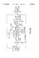
- FIG. 2illustrates an exemplary photonically controlled transmit ultrasonic probe in accordance with the present invention
- FIG. 3illustrates an exemplary photonically controlled receive ultrasonic probe in accordance with the present invention
- FIGS. 4a and 4billustrate an optical or electrical adder module that can be incorporated in the receive ultrasonic probe of FIG. 3;
- FIG. 5illustrates an exemplary multi-wavelength polarization controller, shown for three channels, that can be incorporated in the embodiments of FIGS. 3 and 4 in accordance with the present invention.
- FIGS. 6a and 6bare transmissive and reflective acousto-optic tunable filter (AOTF) based multi-wavelength photonic signal control (PSC) modules which serves as a switched delay line incorporated in the embodiments of FIGS. 3 and 4 in accordance with the present invention.
- AOTFacousto-optic tunable filter
- PSCphotonic signal control
- Optical fibersare extremely low loss (e.g., ⁇ 0.5 dB/km), highly flexible (in terms of twisting and bending), lightweight, electromagnetic interference (EMI) free, very wide radio frequency (rf) bandwidth (e.g., 100 Ghz) optical energy guides.
- EMIelectromagnetic interference
- rfradio frequency
- an optical fiber cableis a near perfect choice in terms of electrical, optical and mechanical properties for a conduit of optical energy that controls and senses ultrasonic energy at the intracavity site.
- a wideband intracavity ultrasonic probewould have at most a few hundred independent transducers (or processing channels) with a few meters of fiber for placing the transducer at remote locations inside a body. Also, there is a relatively low power consumption requirement (both at the probe and in the external beamformer) due to the short (e.g., 1 cm) endoscopic field of view. Unlike rf and microwave antenna arrays that require short nanosecond regime time delays that can in most cases be implemented using non-fiber delay designs, the high frequency ultrasonic application requires very long delays that go into the microsecond regime.
- the low loss of optical fibersprovides an excellent medium to get these rather long time delays using small reels of fibers (coils of optical fibers, e.g., 1 cm in diameter).
- FOsdoes have its limitations, particularly in the optical interconnection and coupling area where optical losses can quickly add up, and the low noise optical modulation area where optical noise increases in the much higher radar band.
- ultrasonic intracavity applicationsrequire lower operation frequencies (e.g., ⁇ 100 Mhz), fewer independent array processing channels, with low power dissipation and consumption.
- WDMchannel optical wavelength division multiplexing
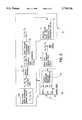
- FIG. 1shows a block diagram of the basic photonically controlled ultrasonic array system 10.
- the photonically controlled ultrasonic array system 10includes a wave division multiplexed (WDM) photonic beamformer 11, an ultra-thin, zero dispersion intracavity optical fiber cable 12, and a WDM photonic miniature ultrasonic array intracavity probe 13.
- WDMwave division multiplexed
- the first part of the systemis the WDM photonic beamformer 11 that optically generates the required beamforming signal set parameters, i.e., ultrasonic signal center frequency, instantaneous bandwidth or pulse width, amplitude variation or pulse shape, transmit pulse peak power, receive signal modulation depth/dynamic range, signal set time/phase delays, and ultrasonic beam scan width and scan resolution.
- the required beamforming signal set parametersi.e., ultrasonic signal center frequency, instantaneous bandwidth or pulse width, amplitude variation or pulse shape, transmit pulse peak power, receive signal modulation depth/dynamic range, signal set time/phase delays, and ultrasonic beam scan width and scan resolution.
- the photonic beamformer 11includes certain standard or existing and/or commercially-available WDM optics such as FO multiplexers (MUX), demultiplexers (DEMUX), optical fibers with gratings, dispersive optical fibers, FO circulators, plus other general polarization optics such as polarizers (P), polarization beam splitters (PBSs), and polarization maintaining fibers (PMFs) as described below. More importantly, in addition to the novel configuration, the photonic beamformer 11 includes two novel WDM modules 21 and 22.
- WDM opticssuch as FO multiplexers (MUX), demultiplexers (DEMUX), optical fibers with gratings, dispersive optical fibers, FO circulators, plus other general polarization optics such as polarizers (P), polarization beam splitters (PBSs), and polarization maintaining fibers (PMFs) as described below. More importantly, in addition to the novel configuration, the photonic beamformer 11 includes two novel WDM modules 21 and 22.
- the first novel moduleis a photonic signal control (PSC) module acting as a multi-wavelength optical delay line module 21 (FIGS. 2 and 3) using two high speed (i.e., ⁇ 10 microseconds wavelength switching time), bulk acousto-optic tunable filters 61, 62 (FIG. 6) that provided collinear, high power, multi-wavelength optical input and output beams.
- This wavelength selection module 21also provides high optical throughput (e.g., 80% efficiency) and excellent (e.g., -30 db) optical blockage of the unwanted leakage (undiffracted) light, preventing noise propagation when such modules are cascade connected to provide many variable switched signal time delays.
- the second novel module in the photonic beamformer 11is another multi-wavelength module 22 (FIGS. 2 and 3) that adjusts the optical polarization of the optical beams at various stages of the polarization sensitive ultrasonic control system 10.
- This polarization controller 22is important for high efficiency operation of the overall system, and is based on an interferometric, zero-path length difference optical design, using a variety of low loss two dimensional pixelated thin-film device arrays of various types of liquid crystals such as twisted nematic, parallel-rub birefringent-mode, and ferroelectric liquid crystals. These liquid crystal devices form the desired polarization mode converters, phase shifters and half-wave plates used to form this novel polarization control module 22.
- the photonic beamformer 11is remotely connected to the ultrasonic probe via a single zero-dispersion optical fiber 12.
- the zero-dispersion optical fiber 12is desired so as to not introduce any relative wavelength dependent time delays, as this would likely cause unwanted ultrasonic beam location error in the system, although this type of error can be compensated for if a single zero-dispersion fiber is not used.
- FIGS. 2 and 3respectively show the present inventor's photonically controlled transmit 20 and receive ultrasonic probe 30 system architectures. The novel aspects of these photonically controlled ultrasonic probe systems 10, 20 and 30 are described herein with like parts being provided with like reference numbers.
- a WDM beamformer 11is used to minimize both the beamforming hardware, and more importantly, the intracavity remote FO cable 12 and front-end optical sensor or probe 13 hardware. This reduces the number of FO point-to-point interconnections, and thus minimize excessive coupling losses.
- the processed light energyessentially travels in one physical optical channel that is sometimes an optical fiber and sometimes a free-space or solid-optics channel. Only at the ultrasonic system's front-end 13, and possibly a receive electrical adder 39 (described below), are the multiple wavelengths separated into different physical channels. This leads to major hardware reduction, and also allows the use of a flexible, ultra-thin (e.g., 100 micron), hair-like, optical cable 12 for remote intracavity operation.
- ultra-thine.g. 100 micron
- N-wavelength broadband optical sourcee.g., CW or pulsed laser
- a single broadband optical modulator 24that produces short optical pulses (e.g., 0.1 ⁇ s width) of any particular shape at a desired rate (e.g., 10 Khz) according to a transmit ultrasonic rf signal.
- the optical pulse output from the modulator 24might have different state of polarization (SOP) for the different wavelengths.
- SOPstate of polarization
- the N-wavelengths input to the polarization-based delay module 21should be of a given linear polarization (e.g., p or parallel polarization)
- a multi-wavelength polarization control module 22is used.
- the different wavelengthsacquire different time delays, as required for forming the desired ultrasonic beam at the remote probe location.
- these N-wavelength signalsare fed through a zero-dispersion fiber cable 12 that feeds this optical energy to the probe 13 intracavity site in the body where the ultrasonic energy medical procedure is desired.
- non-imaging modalitiessuch as therapy, lithotripsy and surgery (e.g., dental and cardiac)
- only the transmit operation of the intracavity probe 13is generally required.
- the N-wavelength time delayed optical energyis demultiplexed by a demultiplexer 26 (e.g., via a tiny diffractive optical element such as a grating) in the intracavity probe 13.
- a demultiplexer 26e.g., via a tiny diffractive optical element such as a grating
- These physically separated N light beamsthen shine on an N-element ultrasonic transducer array 27 that generates the desired ultrasonic beam at the required intracavity site.
- the N delayed light pulsescould activate N photoconductive switches (PCSs) that electrically drive N piezoelectric transducer elements.
- PCSsphotoconductive switches
- Another optionis to replace the PCSs with a photoacoustic material.
- FIG. 3shows a receive-only photonically controlled ultrasonic probe system 30 that, in effect, uses many of the same modules used for the transmit-only probe system 20.
- a multi-wavelength polarization control module 22is used, at this time, the receive ultrasonic pulse modulated optical beams coming through the remote zero-dispersion fiber 12 might have different SOPs for the different wavelengths.
- the continuous multi-wavelength source 33directly (without passing through the delay line module 21) feeds the remote front-end sensor array 37 through the optical fiber cable 12, and thus acts as a continuous local oscillator for the receive front-end ultrasonic sensor array 37.
- a general fiber-grating sensor array 37is shown in FIG. 3 for ultrasonic energy detection.
- this WDM FO sensor array 37As developed by the FO sensor community, there are several methods to form this WDM FO sensor array 37, including using acoustically sensitive fiber Bragg grating tips with light absorbers and fiber gratings, and Zinc Oxide (ZnO) piezoelectric coated fibers (these act as all-fiber optical phase shifters).
- the traveling ultrasonic pressure wavecompresses and expands the fiber grating, hence optically phase and wavelength modulating the light in the fiber channel.
- Both interferometric and non-interferometric optical modulation detection techniquescan be used for the ultrasonic fiber sensor receive array 37, and these have been discussed in FO sensor literature.
- ultrasonic receive pulse modulated optical signals at different wavelengthsare transmitted from the receive array 37 through optical fibers and combined by a passive wavelength multiplexer/demultiplexer 36, travel through the zero-dispersion fiber 12 into the single physical channel multi-wavelength time delay module 21 after passing through an optical circulator 38, commercially available through, e.g., Melles-Griot in Irvine, Calif., and the polarization controller 22.
- the received ultrasonic signal modulationsare added via optical or electrical means 34, as shown in FIG. 4.
- the different wavelengthsare added in intensity, and the heterodyne wavelength mixing harmonics, if present, is out of the electrical bandwidth of a photoreceiver 41.
- the modulated light ⁇ 1 , ⁇ 2 , ⁇ 3 without relative delaysare detected by a high dynamic range photo receiver 41, such as an avalanche photodiode, with threshold logic.
- the detected light signalis passed through a band-pass electrical filter 42, the band-pass filtered signal is then amplified by a low noise amplifier 43, passed through another filter 44 and a high gain amplifier 45 for final output, in this example. This then gives the desired linear summation of the ultrasonic receive pulse modulations.
- the different wavelengths or ultrasonic receive pulse signal modulationsare detected by respective photoreceivers 53a, 53b, 53c after being separated by a WDM demultiplexer 51 and passed through an optical filter bank 52.
- the resultis filtered by an electrical filter 56 before output.
- linear signal summation in an electrical adder 55is done after photo-detection and amplification by respective low noise amplifiers 54a, 54b, 54c each with threshold logic.
- This methodadds more hardware, but can improve receive signal dynamic range and reduce nonlinear effects in the optoelectronics.
- FIGS. 4a and 4bare not new, and have been proposed by the present inventor for antenna and radar array processing applications.
- FIG. 5shows an exemplary novel multi-wavelength polarization controller (PC) module 22.
- PCmulti-wavelength polarization controller
- this PC module 22is a multichannel (e.g., 100 channels for 100 wavelengths) module that uses compact, low cost, and low interconnection complexity 3-D bulk optics with low loss 2-D electrically controlled pixelated thin-film liquid crystal devices. This results in a high channel count, high optical throughput PC module.
- collinear, unknown SOP broadband light containing different colorsenters the PC module 22 via an optical fiber or free-space/solid optics entry port 51a.
- the spherical lens S1makes those beams collinear.
- Lightthen passes through two pixelated and orthogonally oriented polarization mode converters TN1 and TN2.
- These mode converters TN1 and TN2can be 90 degree twist NLC devices, where a first mode converter TN1 rotates p to s (or vertical linear) SOP, with full 90 degree rotation obtained when the device has no applied voltage, while essentially no linear SOP rotation when fully on, i.e., when a high voltage (e.g., 5 V) is applied. More importantly, the first mode converter TN1 provides high resolution grey-scale linear SOP rotation between 90 and zero degrees for a variable applied voltage.
- the second mode converter TN2is a similar, but orthogonally oriented 90 degree twist NLC device.
- the second mode converter TN2rotates s to p linear SOP over a grey-scale rotation angle controlled by the variable applied voltage.
- the first and second mode converters TN1 and TN2are used to take any input polarization, and generate light with near equal amplitude p and s SOPs that are then individually directed by the cube broadband polarizing beam splitter (PBS) 53 to path 2 and path 1, which are designed to be equal, respectively, in the Mach-Zehnder interferometer 52.
- PBScube broadband polarizing beam splitter
- First and second phase shifters P1 and P2act as analog grey-scale control optical phase shifters providing the required optical phase shift of the s and p SOP beams, respectively, that occur after the PBS 53.
- the first and second phase shifters P1 and P2are preferably parallel-rub, birefringent-mode, electrically controllable NLC devices.
- First and second 90° polarization rotators R1 and R2operate 180° out-of-phase, and determine whether p or s linear SOP is desired at the output of the PC module 22.
- the first and second rotators R1 and R2act as broadband 90 degree on/off mode linear SOP rotators, and can be 90 degree twist NLC devices or binary ferroelectric liquid crystal (FLC) devices.
- FLCbinary ferroelectric liquid crystal
- the light at the other output portcan be maximized through a feedback loop (not shown).
- the high extinction fixed polarizers P1(s) and P2(p)can suppress any unwanted polarization noise in the PC module 22.
- the spherical lenses S2 and S3 and gratings G2 and G3form N:1 multiplexers 57a, 57b which are used to recombine the different wavelengths to create the desired s or p SOP collinear multi-wavelength beam.
- the PC module 22is designed to exist as one solid-optical block with no moving parts and no free-space gaps.
- the speed of the PC module 22depends on the switching speed of the electrically activated devices and also on the feedback loop processing speed. With current high speed (e.g., Mhz rate) photosensor arrays and digital electronic processing power, at present, the PC module speed is limited by the millisecond regime response of the grey-scale single cell twisted and birefringent-mode NLC devices that make up the first and second mode converters TN1, TN2, and the first and second phase shifters P1 and P2. With faster grey-scale optical phase and SOP mode conversion devices, the PC module 22 can operate in the few microseconds regime. Hence, this PC module 22 can be successfully used in the proposed photonically controlled ultrasonic probe system.
- FIGS. 6a and 6bshow novel, multi-wavelength input light, bulk AOTF device pair-based photonic signal control (PSC) module structure 21 that can perform various electrical and optical signal processing and control functions including a switched delay line.
- PSCphotonic signal control
- this PSC module 21is configured as a multi-wavelength variable optical delay line, where high speed (e.g., ⁇ 10 microseconds) switched variable or fixed time delay can be obtained by either trammissive (FIG. 6a) or reflective (FIG. 6b) optical structure designs.
- the optical delay line for long time delays (in microseconds), such as required for the ultrasonic probe,can be made by various known methods using dispersive or non-dispersive polarization maintaining fibers (PMFs), PMFs or non-PMFs with spatially distributed gratings, and dispersive or non-dispersive PMFs.
- the PSC module 21 designuses light having a linear SOP at the critical beam splitting, switching, and combining planes, such as at the bulk AOTFs, PBSs and polarizer planes.
- This PSC module 21provides certain unique properties that are not available in other known multi-wavelength optoelectronic PSC modules.
- OSPoptical signal processing
- PCS module 21in any cascaded optical structure such as a K-bit optical delay system formed by serially cascading K PSC modules 21 shown in FIG. 2. Both input and output light for this PSC module 21 have the same linear SOP, e.g., p SOP as shown in FIGS. 6a and 6b. If the input light is not in a linear SOP, the multiwavelength active PC module 67, identical to PC module 22, can be used to produce the desired linear SOP for all the colors.
- a passive PC module 67can also be provided using a PBS-Mirror-90 degree polarization rotator arrangement to convert all input light into two adjacent beams that have the same linear SOP.
- This PSC module 21relies on an active noise reduction method using a second AOTF 62 in the in-line optical structure and Fourier plane filtering using a undiffracted beam spatial block 63.
- the input lighthas only three distinct wavelengths ⁇ 1 , ⁇ 2 , ⁇ 3 with the same p SOP in this example for simplicity.
- the first AOTF 61is driven by an rf frequency f2 that diffracts and selects the 2nd wavelength from the input light, for example. Other frequencies would cause the AOTF 61 to select other frequencies. Due to the birefringent nature of the AOTF bulk crystal, the diffracted light has the s or orthogonal SOP compared to the input light.
- the first AOTF 61shows a non-collinear AOTF design where the acoustic wave and optical wave travel in orthogonal directions. Bulk AOTFs are also made in collinear interaction geometries. In general, AOTFs are designed such that the diffraction angle is insensitive to the input band of wavelengths that is also called the optical filter 3-dB bandwidth.
- This PCS module 21can be used with both non-collinear (FIG. 6) and collinear interaction geometry AOTFs. Furthermore, this PCS module 21 does not require that the AOTF diffraction angle be essentially wavelength insensitive to give the desired multi-wavelength collinear output beam.
- imaging optics in the modulemake all the wavelengths collinear, even if they are physically separated at the Fourier plane of the second spherical lens S2.
- the first AOTF 61 rf drive frequenciesselect the colors that are to go to an external signal processing port or selected wavelength light diverter formed by two polarizing beam splitters 64 and 65 which respectively divert and re-align a beam of one or more of the wavelengths, e.g., ⁇ 2 , into an optical processing element, such as a delay line 66 and an optional polarizing controller 67 as shown in FIG. 6a.
- the two polarizing beam splitters 64 and 65are replaced by a single polarizing beam splitter 70 in combination with mutually opposing mirrors 71 and 72 on the transverse sides of the beam splitter 70 and a Faraday 45° rotator 73 on one transverse side of the beam splitter 70.
- the undiffracted lightcontains all the colors that were not selected, plus some leakage light of the colors selected by the first AOTF 61.
- This leakage lightis noise in the PSC module 21, and should be removed.
- the use of the second orthogonally oriented AOTF 62removes the leakage light noise. This is done by feeding the second AOTF 62 with rf frequencies that select all the colors not selected by the first AOTF 61. In this way, leakage light from both AOTFs 61 and 62 can be spatially separated from the selected colors, and hence physically blocked at the Fourier plane of fourth spherical lens S4 using the undiffracted beam block 63.
- the first AOTF 61selects the colors (wavelengths) that need signal processing, while the second AOTF 62 acts as a leakage noise filter and multi-wavelength beam recombiner.
- polarizers 68a and 68b at the input and output of the PSC module 21, as well as a rotator 69 at the outputcan be included.
- the final light output of the PSC module 21is collinear, of one high extinction ratio linear SOP, and contains the colors that have undergone the required optical signal processing (e.g., phase shift, time delay, amplitude control, etc.). Multi-wavelength collinearity at the output of the PSC module 21 makes simpler and more efficient FO coupling, thus allowing the use of optical fibers with this module design.
- the second AOTF 62can also be oriented in the same way as first AOTF 61 (as shown for the reflective delay line application). In this case, all the diffracted and selected beams have the same positive Doppler shift.
- the issue of Doppler shiftsis important when heterodyne signal processing is involved using the PSC module 21. Both positive and negative Doppler shift AOTF operations are possible with the PSC module 21, giving flexibility to the system designer.
- this PSC module 21can be used for different optical signal processing tasks with appropriate placement of optics in the free-space path.
- the two PBSs between the second and third spherical lenses S2 and S3can be replaced by a thick birefringent crystal or thin-birefringent film cell to form an optical phase shifter, as the diffracted light will suffer a different optical phase shift compared to the undiffracted light from the first AOTF 61.
- a variable broadband optical phase shifteris formed using the PSC module 21.
- the PSC module 21is as a high speed programmable optical filter for a broadband high power light source that eventually feeds wavelength sensitive photonic sensors and instruments used in other medical, scientific, industrial and environmental (e.g., spectroscopic) applications.
- the PSC module 21does not have the two PBSs 64 and 65 and delay line 66, and colors are selected by controlling the AOTF drive frequencies.
- the high speed programmable optical filtercan also be used for multi-wavelength optical gain equalization such as needed in WDM FO communication networks. In this case, gain equalization is achieved by controlling the amplitude of the rf drive frequencies for the two AOTFs 61 and 62.
- the PSC module 21is configured as a switched multi-wavelength optical delay line for ultrasonic band (e.g., 100 kHz-100 MHz) modulation, photonic signal processing.
- ultrasonic bande.g. 100 kHz-100 MHz
- the disclosed photonically controlled ultrasonic probe system 10uses a single FO signal processing and remoting channel that greatly helps in reducing inter-channel differential time delay errors, as all N wavelength channels essentially pass through the same photonic control modules.
- a single FO signal processing and remoting channelthat greatly helps in reducing inter-channel differential time delay errors, as all N wavelength channels essentially pass through the same photonic control modules.
- an N-element FO ultrasonic sensor (receive) array 37can be embedded alongside the N-element ultrasonic transmit (T) array 27, forming an ultracompact photonically controlled ultrasonic probe.
- broadband (WDM-type) optical (semiconductor and doped-fiber) amplifierscan be used in this PSC and PC module based control system 10.
Landscapes
- Physics & Mathematics (AREA)
- Acoustics & Sound (AREA)
- Engineering & Computer Science (AREA)
- Radar, Positioning & Navigation (AREA)
- Remote Sensing (AREA)
- Computer Networks & Wireless Communication (AREA)
- General Physics & Mathematics (AREA)
- Multimedia (AREA)
- Optical Modulation, Optical Deflection, Nonlinear Optics, Optical Demodulation, Optical Logic Elements (AREA)
Abstract
Description
1) Field of the Invention
The present invention relates to a fiber optic based ultrasonic intracavity photonic tool for ultrasonic transmit probing (e.g., acoustic knife) and ultrasonic receive probing (e.g., imaging) in human patients and other living creatures.
2) Discussion of Related Art
There is an increasing need for developing minimally invasive low cost medical tools for therapeutic, diagnostic and surgical applications. In particular, there is a push for developing ultrasonic energy-based intracavity or endoscopic (i.e., inserted into a cavity such as a blood vessel, esophagus or rectum) probes, as ultrasonic energy offers excellent properties for imaging, healing or ablating selected parts of a human body and other life forms. One recent example for ultrasonic surgery is called High-Intensity Focussed Ultrasound (HIFU) where an "acoustic knife" operating at a typical ultrasonic frequency of 55 Khz is used to thermally ablate malignant tissue inside the body without effecting the surrounding healthy tissue. HIFU has the potential to provide bloodless, minimal patient stress, short recovery time and fast surgery, thus benefiting both the patient and the health care provider. Another important example of endoscopic ultrasonics is lithotripsy, where an intracavity probe operating around 20-40 Khz is inserted near a kidney stone to be destroyed. Both HIFU and lithotripsy applications use relatively low ultrasonic frequencies (<100 Khz), particularly when compared to the 5-15 Mhz band used in diagnostic, external, cavity imaging ultrasound.
Today, with endoscopic applications in mind, a very high ultrasonic frequency (e.g., 100 Mhz) probe with high (>50%) instantaneous bandwidths is desirable as higher frequencies give higher imaging resolution and smaller physical dimensions of the front-end intracavity transducer array. This allows for placement of probes in small cavities like arteries for imaging blood vessels. N. Born and J. Roelandt, Intravascular Ultrasound, Dordrecht:Kluwer Academic, 1989. Furthermore, in all the previously mentioned ultrasonic applications, it is highly desirable to implement non-mechanical steering of the ultrasonic energy, thus efficiently directing energy to the desired site. In particular, for intracavity probes where front-end transducer space and power are limited, mechanically moving parts must be avoided. Hence, ultrasonic beamforming should be implemented electronically, as is done in most high end ultrasound imaging machines.
It is desirable to have ultrasonic energy control systems that, with minimal hardware changes, operate over wide tunable and instantaneous bandwidths, such as required for the different ultrasonic medical modes. A potentially compact, high performance, photonic beamforming controller for wideband ultrasonic arrays is disclosed herein using current, mature fiber-optic (FO) technology to develop low cost, high performance ultrasonic system. A novel FO control system suited for intracavity ultrasonic probes, particularly for wide instantaneous bandwidth high resolution imaging, is also disclosed.
Specifically, the invention includes a photonically controlled ultrasonic array system having a wave division multiplexed photonic beamformer, an optical fiber cable, and a wave division multiplexed photonic ultrasonic array remote probe.
In an ultrasonic transmission embodiment or transmission section, the optical fiber cable receives wave division multiplexed light from the wave division multiplexed photonic beamformer, and the wave division multiplexed photonic ultrasonic array remote probe generates ultrasonic energy from the wave division multiplexed light received from the optical fiber cable.
In an ultrasonic receive embodiment or reception section, the wave division multiplexed photonic beamformer includes a multiple wavelength light source which acts as a continuous local oscillator for the wave division multiplexed photonic ultrasonic array remote probe, the optical fiber cable receives multiple wavelength light from the light source, and the wave division multiplexed photonic ultrasonic array remote probe modulates the multiple wavelength light in response to received ultrasonic energy and transmits the modulated multiple wavelength light through the optical fiber cable to the wave division multiplexed photonic beamformer.
The invention includes the use of a novel multiple channel polarization control module having a wavelength demultiplexer which physically separates the different wavelength light beams, two pixelated and orthogonally oriented polarization mode converters which receive and convert the polarization of the different wavelength light beams, a Mach-Zehnder interferometer or the like including a cube beamsplitter, a cube broadband polarizing beam splitter (PBS) which receives near equal amplitude p and s states of polarization (SOPs) from the polarization mode converters and individually directs the p and s SOPs to separate first and second paths, which are designed to be equal, respectively, in the Mach-Zehnder interferometer. Additionally, this polarization control module has first and second phase shifters in the first and second paths which provide the required optical phase shift of the s and p SOP beams, first and second 90° polarization rotators operating 180° out-of-phase to determine whether p or s linear SOP is output from the polarization control module, wherein by controlling the first and second mode converters, the first and second phase shifters, and the first and second rotators, the two beams interfering at the cube beamsplitter can be made to be equal in amplitude, in-phase or 180 degree out-of-phase, and hence of the desired p or s linear SOP. Further, multiplexers recombine the different wavelengths to create the desired s or p SOP collinear multi-wavelength output beams.
The invention includes the use of a novel multi-wavelength photonic signal control module having a first acousto-optic tunable filter (AOTF) to spatially separate at least one selected wavelength of light from others in a multiwavelength beam, an external signal processing port which diverts and realigns a beam of one or more of the wavelengths into an optical processing element, the external signal processing port re-aligning the selected light in an optical path of the photonic signal control module, a second AOTF and a spatial block for Fourier plane filtering and to reduce noise.
Although other, non-medical applications are possible with the photonically controlled ultrasonic system disclosed herein, the exemplary embodiments involve medical applications.
The invention will now be described by way of exemplary embodiments shown in the accompanying drawing figures in which:
FIG. 1 is a representational block diagram of a photonically controlled ultrasonic probe in accordance with the present invention;
FIG. 2 illustrates an exemplary photonically controlled transmit ultrasonic probe in accordance with the present invention;
FIG. 3 illustrates an exemplary photonically controlled receive ultrasonic probe in accordance with the present invention;
FIGS. 4a and 4b illustrate an optical or electrical adder module that can be incorporated in the receive ultrasonic probe of FIG. 3;
FIG. 5 illustrates an exemplary multi-wavelength polarization controller, shown for three channels, that can be incorporated in the embodiments of FIGS. 3 and 4 in accordance with the present invention; and
FIGS. 6a and 6b are transmissive and reflective acousto-optic tunable filter (AOTF) based multi-wavelength photonic signal control (PSC) modules which serves as a switched delay line incorporated in the embodiments of FIGS. 3 and 4 in accordance with the present invention.
There are several reasons for turning to fiber optics (FOs) for intracavity applications. Optical fibers are extremely low loss (e.g., <0.5 dB/km), highly flexible (in terms of twisting and bending), lightweight, electromagnetic interference (EMI) free, very wide radio frequency (rf) bandwidth (e.g., 100 Ghz) optical energy guides. Compared to a radio frequency (rf) multiwire cable feeding a typical 256 element intracavity probe, an optical fiber cable is a near perfect choice in terms of electrical, optical and mechanical properties for a conduit of optical energy that controls and senses ultrasonic energy at the intracavity site. More importantly, in multiwire cable systems at a high rf such as 50 Mhz required for ultracompact imaging probes, the rf cable losses, EMI, and electronic beamformer design are not trivial. In particular, running a multi-wire cable within the human body is potentially dangerous for the patient because of possible high rf fields and electrical shock hazards. The use of fiber optics avoids these hazards.
Unlike the multitude of transducers used in optically controlled radar beamforming, a wideband intracavity ultrasonic probe would have at most a few hundred independent transducers (or processing channels) with a few meters of fiber for placing the transducer at remote locations inside a body. Also, there is a relatively low power consumption requirement (both at the probe and in the external beamformer) due to the short (e.g., 1 cm) endoscopic field of view. Unlike rf and microwave antenna arrays that require short nanosecond regime time delays that can in most cases be implemented using non-fiber delay designs, the high frequency ultrasonic application requires very long delays that go into the microsecond regime. Hence, the low loss of optical fibers provides an excellent medium to get these rather long time delays using small reels of fibers (coils of optical fibers, e.g., 1 cm in diameter). Nevertheless, FOs does have its limitations, particularly in the optical interconnection and coupling area where optical losses can quickly add up, and the low noise optical modulation area where optical noise increases in the much higher radar band. Fortunately, unlike advanced radar, ultrasonic intracavity applications require lower operation frequencies (e.g., <100 Mhz), fewer independent array processing channels, with low power dissipation and consumption.
Hence, described herein is a novel FO-based ultrasonic intracavity system that minimizes FO interconnection and coupling complexity, and provides a high efficiency and powerful (particularly in terms of operational bandwidths) photonic tool for ultrasonic transmit and receive probing. In particular, channel optical wavelength division multiplexing (WDM) is used to minimize FO interconnection and coupling complexity. WDM has been proposed for use by the optical telecommunications industry, FO sensor industry, and phased array antenna/radar community for hardware reduction.
FIG. 1 shows a block diagram of the basic photonically controlledultrasonic array system 10. The photonically controlledultrasonic array system 10 includes a wave division multiplexed (WDM)photonic beamformer 11, an ultra-thin, zero dispersion intracavityoptical fiber cable 12, and a WDM photonic miniature ultrasonicarray intracavity probe 13.
The first part of the system is the WDMphotonic beamformer 11 that optically generates the required beamforming signal set parameters, i.e., ultrasonic signal center frequency, instantaneous bandwidth or pulse width, amplitude variation or pulse shape, transmit pulse peak power, receive signal modulation depth/dynamic range, signal set time/phase delays, and ultrasonic beam scan width and scan resolution.
Thephotonic beamformer 11 includes certain standard or existing and/or commercially-available WDM optics such as FO multiplexers (MUX), demultiplexers (DEMUX), optical fibers with gratings, dispersive optical fibers, FO circulators, plus other general polarization optics such as polarizers (P), polarization beam splitters (PBSs), and polarization maintaining fibers (PMFs) as described below. More importantly, in addition to the novel configuration, thephotonic beamformer 11 includes twonovel WDM modules
The first novel module is a photonic signal control (PSC) module acting as a multi-wavelength optical delay line module 21 (FIGS. 2 and 3) using two high speed (i.e., <10 microseconds wavelength switching time), bulk acousto-optictunable filters 61, 62 (FIG. 6) that provided collinear, high power, multi-wavelength optical input and output beams. Thiswavelength selection module 21 also provides high optical throughput (e.g., 80% efficiency) and excellent (e.g., -30 db) optical blockage of the unwanted leakage (undiffracted) light, preventing noise propagation when such modules are cascade connected to provide many variable switched signal time delays.
The second novel module in thephotonic beamformer 11 is another multi-wavelength module 22 (FIGS. 2 and 3) that adjusts the optical polarization of the optical beams at various stages of the polarization sensitiveultrasonic control system 10. Thispolarization controller 22 is important for high efficiency operation of the overall system, and is based on an interferometric, zero-path length difference optical design, using a variety of low loss two dimensional pixelated thin-film device arrays of various types of liquid crystals such as twisted nematic, parallel-rub birefringent-mode, and ferroelectric liquid crystals. These liquid crystal devices form the desired polarization mode converters, phase shifters and half-wave plates used to form this novelpolarization control module 22.
As shown in FIG. 1, thephotonic beamformer 11 is remotely connected to the ultrasonic probe via a single zero-dispersionoptical fiber 12. The zero-dispersionoptical fiber 12 is desired so as to not introduce any relative wavelength dependent time delays, as this would likely cause unwanted ultrasonic beam location error in the system, although this type of error can be compensated for if a single zero-dispersion fiber is not used. Much work has been done by the FO sensor community for developing WDM and grating-based FO strain sensors, and these concepts can be used for theultrasonic system 10. FIGS. 2 and 3 respectively show the present inventor's photonically controlled transmit 20 and receive ultrasonic probe 30 system architectures. The novel aspects of these photonically controlledultrasonic probe systems
As mentioned above, aWDM beamformer 11 is used to minimize both the beamforming hardware, and more importantly, the intracavityremote FO cable 12 and front-end optical sensor or probe 13 hardware. This reduces the number of FO point-to-point interconnections, and thus minimize excessive coupling losses. As shown for both the transmit-mode probe system 20 in FIG. 2, and the receive-mode probe system 30 in FIG. 3, the processed light energy essentially travels in one physical optical channel that is sometimes an optical fiber and sometimes a free-space or solid-optics channel. Only at the ultrasonic system's front-end 13, and possibly a receive electrical adder 39 (described below), are the multiple wavelengths separated into different physical channels. This leads to major hardware reduction, and also allows the use of a flexible, ultra-thin (e.g., 100 micron), hair-like,optical cable 12 for remote intracavity operation.
For transmit-only operation as shown in FIG. 2, light from a high power (e.g., 1 Watt CW) N-wavelength broadband optical source (e.g., CW or pulsed laser) 23 is fed to a single broadbandoptical modulator 24 that produces short optical pulses (e.g., 0.1 μs width) of any particular shape at a desired rate (e.g., 10 Khz) according to a transmit ultrasonic rf signal. This N=3 wavelength (only three wavelengths are shown for simplicity) optical pulse is first fed to the N=3 channelpolarization control module 22, and then into the single physical optical channel, K-bit, switched, FOdelay line module 21. This is because the optical pulse output from themodulator 24 might have different state of polarization (SOP) for the different wavelengths. Because high efficiency operation suggests that the N-wavelengths input to the polarization-baseddelay module 21 should be of a given linear polarization (e.g., p or parallel polarization), a multi-wavelengthpolarization control module 22 is used.
Based on the settings of the variabletime delay module 21, the different wavelengths acquire different time delays, as required for forming the desired ultrasonic beam at the remote probe location. These N-wavelength signals (e.g., N=100 using a 100 nm optical bandwidth with a 1 nm channel spacing) with appropriate delays are fed through a zero-dispersion fiber cable 12 that feeds this optical energy to theprobe 13 intracavity site in the body where the ultrasonic energy medical procedure is desired. In non-imaging modalities such as therapy, lithotripsy and surgery (e.g., dental and cardiac), only the transmit operation of theintracavity probe 13 is generally required. In this case, the N-wavelength time delayed optical energy (transmit pulse) is demultiplexed by a demultiplexer 26 (e.g., via a tiny diffractive optical element such as a grating) in theintracavity probe 13. These physically separated N light beams then shine on an N-elementultrasonic transducer array 27 that generates the desired ultrasonic beam at the required intracavity site. For instance, the N delayed light pulses could activate N photoconductive switches (PCSs) that electrically drive N piezoelectric transducer elements. Another option is to replace the PCSs with a photoacoustic material. These options, along with advances in micromachining technology, can result in an ultracompact optically fedultrasonic probe 13.
FIG. 3 shows a receive-only photonically controlled ultrasonic probe system 30 that, in effect, uses many of the same modules used for the transmit-only probe system 20. Again, a multi-wavelengthpolarization control module 22 is used, at this time, the receive ultrasonic pulse modulated optical beams coming through the remote zero-dispersion fiber 12 might have different SOPs for the different wavelengths. In FIG. 3, it is important to note that the continuousmulti-wavelength source 33 directly (without passing through the delay line module 21) feeds the remote front-end sensor array 37 through theoptical fiber cable 12, and thus acts as a continuous local oscillator for the receive front-endultrasonic sensor array 37. By example, a general fiber-gratingsensor array 37 is shown in FIG. 3 for ultrasonic energy detection. As developed by the FO sensor community, there are several methods to form this WDMFO sensor array 37, including using acoustically sensitive fiber Bragg grating tips with light absorbers and fiber gratings, and Zinc Oxide (ZnO) piezoelectric coated fibers (these act as all-fiber optical phase shifters). The traveling ultrasonic pressure wave compresses and expands the fiber grating, hence optically phase and wavelength modulating the light in the fiber channel. Both interferometric and non-interferometric optical modulation detection techniques can be used for the ultrasonic fiber sensor receivearray 37, and these have been discussed in FO sensor literature.
These ultrasonic receive pulse modulated optical signals at different wavelengths are transmitted from the receivearray 37 through optical fibers and combined by a passive wavelength multiplexer/demultiplexer 36, travel through the zero-dispersion fiber 12 into the single physical channel multi-wavelengthtime delay module 21 after passing through anoptical circulator 38, commercially available through, e.g., Melles-Griot in Irvine, Calif., and thepolarization controller 22. In this receive system 30, after multichannel signal processing (e.g., relative time delay cancellation) via the multi-channelphotonic delay module 21, the received ultrasonic signal modulations are added via optical or electrical means 34, as shown in FIG. 4.
In the optical method shown in FIG. 4(a), the different wavelengths are added in intensity, and the heterodyne wavelength mixing harmonics, if present, is out of the electrical bandwidth of aphotoreceiver 41. Specifically, the modulated light λ1, λ2, λ3 without relative delays are detected by a high dynamicrange photo receiver 41, such as an avalanche photodiode, with threshold logic. The detected light signal is passed through a band-passelectrical filter 42, the band-pass filtered signal is then amplified by alow noise amplifier 43, passed through anotherfilter 44 and ahigh gain amplifier 45 for final output, in this example. This then gives the desired linear summation of the ultrasonic receive pulse modulations.
Using the electrical method shown in FIG. 4(b), the different wavelengths or ultrasonic receive pulse signal modulations are detected byrespective photoreceivers WDM demultiplexer 51 and passed through anoptical filter bank 52. The result is filtered by anelectrical filter 56 before output. In this case, linear signal summation in anelectrical adder 55 is done after photo-detection and amplification by respectivelow noise amplifiers
FIG. 5 shows an exemplary novel multi-wavelength polarization controller (PC)module 22. Unlike previous polarization control modules that rely on single channel fiber and integrated-optic (IO) devices that are high loss and expensive to produce, thisPC module 22 is a multichannel (e.g., 100 channels for 100 wavelengths) module that uses compact, low cost, and low interconnection complexity 3-D bulk optics with low loss 2-D electrically controlled pixelated thin-film liquid crystal devices. This results in a high channel count, high optical throughput PC module.
In the most general case, collinear, unknown SOP broadband light containing different colors enters thePC module 22 via an optical fiber or free-space/solidoptics entry port 51a. A 1:Nspatial wavelength demultiplexer 51 including diffraction grating G1 (or any other wavelength spatially dispersive optical element, e.g., a prism) and a spherical lens S1 physically separates the different wavelength light beams. The spherical lens S1 makes those beams collinear. Light then passes through two pixelated and orthogonally oriented polarization mode converters TN1 and TN2. These mode converters TN1 and TN2 can be 90 degree twist NLC devices, where a first mode converter TN1 rotates p to s (or vertical linear) SOP, with full 90 degree rotation obtained when the device has no applied voltage, while essentially no linear SOP rotation when fully on, i.e., when a high voltage (e.g., 5 V) is applied. More importantly, the first mode converter TN1 provides high resolution grey-scale linear SOP rotation between 90 and zero degrees for a variable applied voltage.
The second mode converter TN2 is a similar, but orthogonally oriented 90 degree twist NLC device. In this case, the second mode converter TN2 rotates s to p linear SOP over a grey-scale rotation angle controlled by the variable applied voltage. The first and second mode converters TN1 and TN2 are used to take any input polarization, and generate light with near equal amplitude p and s SOPs that are then individually directed by the cube broadband polarizing beam splitter (PBS) 53 topath 2 andpath 1, which are designed to be equal, respectively, in the Mach-Zehnder interferometer 52.
First and second phase shifters P1 and P2 act as analog grey-scale control optical phase shifters providing the required optical phase shift of the s and p SOP beams, respectively, that occur after thePBS 53. The first and second phase shifters P1 and P2 are preferably parallel-rub, birefringent-mode, electrically controllable NLC devices.
First and second 90° polarization rotators R1 and R2 operate 180° out-of-phase, and determine whether p or s linear SOP is desired at the output of thePC module 22. The first and second rotators R1 and R2 act as broadband 90 degree on/off mode linear SOP rotators, and can be 90 degree twist NLC devices or binary ferroelectric liquid crystal (FLC) devices. By controlling the mode converters TN1, TN2, the phase shifters P1, P2, and the rotators R1 and R2, the two beams interfering at the cube 50:50 beamsplitter (BS) 55 can be made to be equal in amplitude, in-phase or 180 degree out-of-phase, and hence of the desired p or s linear SOP.
By monitoring light levels via a beam splitter-photosensor (not shown) placed between one of the output polarizer P1(s) and P2(p) and a corresponding lens pair S2 or S3 at one of the module output ports (e.g., L1 and/or L2), and hence minimizing this light output, the light at the other output port can be maximized through a feedback loop (not shown). Furthermore, the high extinction fixed polarizers P1(s) and P2(p) can suppress any unwanted polarization noise in thePC module 22. The spherical lenses S2 and S3 and gratings G2 and G3 form N:1multiplexers
Because thisPC module 22 is based on interference of two equal amplitude and similar linear SOP beams, thePC module 22 is designed to exist as one solid-optical block with no moving parts and no free-space gaps. The speed of thePC module 22 depends on the switching speed of the electrically activated devices and also on the feedback loop processing speed. With current high speed (e.g., Mhz rate) photosensor arrays and digital electronic processing power, at present, the PC module speed is limited by the millisecond regime response of the grey-scale single cell twisted and birefringent-mode NLC devices that make up the first and second mode converters TN1, TN2, and the first and second phase shifters P1 and P2. With faster grey-scale optical phase and SOP mode conversion devices, thePC module 22 can operate in the few microseconds regime. Hence, thisPC module 22 can be successfully used in the proposed photonically controlled ultrasonic probe system.
FIGS. 6a and 6b show novel, multi-wavelength input light, bulk AOTF device pair-based photonic signal control (PSC)module structure 21 that can perform various electrical and optical signal processing and control functions including a switched delay line.
As shown in FIGS. 6a and 6b, thisPSC module 21 is configured as a multi-wavelength variable optical delay line, where high speed (e.g., <10 microseconds) switched variable or fixed time delay can be obtained by either trammissive (FIG. 6a) or reflective (FIG. 6b) optical structure designs. The optical delay line for long time delays (in microseconds), such as required for the ultrasonic probe, can be made by various known methods using dispersive or non-dispersive polarization maintaining fibers (PMFs), PMFs or non-PMFs with spatially distributed gratings, and dispersive or non-dispersive PMFs. Note that it may be desirable to use thePC module 67 in the optical delay path, if the optical delay line design scrambles the input linear SOP. ThePSC module 21 design uses light having a linear SOP at the critical beam splitting, switching, and combining planes, such as at the bulk AOTFs, PBSs and polarizer planes.
ThisPSC module 21 provides certain unique properties that are not available in other known multi-wavelength optoelectronic PSC modules. First, because of the bulk nature of the optics used in the module structure, very high peak and CW optical power (e.g., 1 watt) can be processed by this module. Second, the free-space design of thePSC module 21 allows for placement of various optical signal processing (OSP) modules such as an optical delay line or polarization filters or spatial blocks. Third, using currently available high diffraction efficiency (e.g., 90%) bulk AOTFs, high optical efficiency (>80%) can be obtained for thisPCS module 21. This is unlike IO AOTFs. Fourth, for collinear multi-wavelength input light, themodule 21 outputs collinear multiwavelength processed light. This simplifies placement of thePCS module 21 in any cascaded optical structure such as a K-bit optical delay system formed by serially cascadingK PSC modules 21 shown in FIG. 2. Both input and output light for thisPSC module 21 have the same linear SOP, e.g., p SOP as shown in FIGS. 6a and 6b. If the input light is not in a linear SOP, the multiwavelengthactive PC module 67, identical toPC module 22, can be used to produce the desired linear SOP for all the colors. Apassive PC module 67 can also be provided using a PBS-Mirror-90 degree polarization rotator arrangement to convert all input light into two adjacent beams that have the same linear SOP.
ThisPSC module 21 relies on an active noise reduction method using asecond AOTF 62 in the in-line optical structure and Fourier plane filtering using a undiffracted beamspatial block 63. In the example of FIGS. 6a and 6b, the input light has only three distinct wavelengths λ1, λ2, λ3 with the same p SOP in this example for simplicity. Thefirst AOTF 61 is driven by an rf frequency f2 that diffracts and selects the 2nd wavelength from the input light, for example. Other frequencies would cause theAOTF 61 to select other frequencies. Due to the birefringent nature of the AOTF bulk crystal, the diffracted light has the s or orthogonal SOP compared to the input light. Thefirst AOTF 61 shows a non-collinear AOTF design where the acoustic wave and optical wave travel in orthogonal directions. Bulk AOTFs are also made in collinear interaction geometries. In general, AOTFs are designed such that the diffraction angle is insensitive to the input band of wavelengths that is also called the optical filter 3-dB bandwidth. ThisPCS module 21 can be used with both non-collinear (FIG. 6) and collinear interaction geometry AOTFs. Furthermore, thisPCS module 21 does not require that the AOTF diffraction angle be essentially wavelength insensitive to give the desired multi-wavelength collinear output beam. This is because appropriate imaging optics in the module (spherical lenses S1 & S2 and S3 & S4 positioned on either side of theAOFTs 61 and 62) make all the wavelengths collinear, even if they are physically separated at the Fourier plane of the second spherical lens S2.
Thefirst AOTF 61 rf drive frequencies select the colors that are to go to an external signal processing port or selected wavelength light diverter formed by twopolarizing beam splitters delay line 66 and an optionalpolarizing controller 67 as shown in FIG. 6a. In a reflective design, the twopolarizing beam splitters polarizing beam splitter 70 in combination with mutually opposingmirrors beam splitter 70 and aFaraday 45°rotator 73 on one transverse side of thebeam splitter 70. The undiffracted light contains all the colors that were not selected, plus some leakage light of the colors selected by thefirst AOTF 61. This leakage light is noise in thePSC module 21, and should be removed. In thisPSC module 21, the use of the second orthogonally orientedAOTF 62 removes the leakage light noise. This is done by feeding thesecond AOTF 62 with rf frequencies that select all the colors not selected by thefirst AOTF 61. In this way, leakage light from both AOTFs 61 and 62 can be spatially separated from the selected colors, and hence physically blocked at the Fourier plane of fourth spherical lens S4 using theundiffracted beam block 63. Hence, thefirst AOTF 61 selects the colors (wavelengths) that need signal processing, while thesecond AOTF 62 acts as a leakage noise filter and multi-wavelength beam recombiner. Additionally,polarizers PSC module 21, as well as arotator 69 at the output can be included. Thus, the final light output of thePSC module 21 is collinear, of one high extinction ratio linear SOP, and contains the colors that have undergone the required optical signal processing (e.g., phase shift, time delay, amplitude control, etc.). Multi-wavelength collinearity at the output of thePSC module 21 makes simpler and more efficient FO coupling, thus allowing the use of optical fibers with this module design.
Note that thesecond AOTF 62 can also be oriented in the same way as first AOTF 61 (as shown for the reflective delay line application). In this case, all the diffracted and selected beams have the same positive Doppler shift. The issue of Doppler shifts is important when heterodyne signal processing is involved using thePSC module 21. Both positive and negative Doppler shift AOTF operations are possible with thePSC module 21, giving flexibility to the system designer.
As mentioned before, thisPSC module 21 can be used for different optical signal processing tasks with appropriate placement of optics in the free-space path. For example, the two PBSs between the second and third spherical lenses S2 and S3 can be replaced by a thick birefringent crystal or thin-birefringent film cell to form an optical phase shifter, as the diffracted light will suffer a different optical phase shift compared to the undiffracted light from thefirst AOTF 61. If the birefringence is electrically controlled, a variable broadband optical phase shifter is formed using thePSC module 21.
Another application of thePSC module 21 is as a high speed programmable optical filter for a broadband high power light source that eventually feeds wavelength sensitive photonic sensors and instruments used in other medical, scientific, industrial and environmental (e.g., spectroscopic) applications. In this case, thePSC module 21 does not have the two PBSs 64 and 65 anddelay line 66, and colors are selected by controlling the AOTF drive frequencies. The high speed programmable optical filter can also be used for multi-wavelength optical gain equalization such as needed in WDM FO communication networks. In this case, gain equalization is achieved by controlling the amplitude of the rf drive frequencies for the two AOTFs 61 and 62.
Because current bulk AOTFs are available over a very broad spectrum of optical wavelengths, i.e., 200-4500 nm (Brimrose Corp.), a wide variety of applications are possible with thePSC module 21, including the highlighted ultrasonic probe application where thePSC module 21 is configured as a switched multi-wavelength optical delay line for ultrasonic band (e.g., 100 kHz-100 MHz) modulation, photonic signal processing.
The disclosed photonically controlledultrasonic probe system 10 uses a single FO signal processing and remoting channel that greatly helps in reducing inter-channel differential time delay errors, as all N wavelength channels essentially pass through the same photonic control modules. Although we have shown separate photonic systems for the transmit and receive ultrasonic probes, one reversible system is possible with the use of additional transmit-receive optical and electrical switching hardware. In particular, for ultrasonic imaging needs, an N-element FO ultrasonic sensor (receive)array 37 can be embedded alongside the N-element ultrasonic transmit (T)array 27, forming an ultracompact photonically controlled ultrasonic probe. Also, to overcome optical losses, broadband (WDM-type) optical (semiconductor and doped-fiber) amplifiers can be used in this PSC and PC module basedcontrol system 10.
The present invention has been described by way of exemplary embodiments to which it is not limited. The scope of the invention is to be determined in the accompanying claims.
Claims (34)
1. A photonically controlled ultrasonic array system comprising:
a wave division multiplexed photonic beamformer;
an optical fiber cable; and
a wave division multiplexed photonic ultrasonic array remote probe, wherein said wave dispersion multiplex photonic ultrasonic array remote probe is remotely connected to said wave dispersion multiplex photonic beamformer by said optical fiber cable.
2. A photonically controlled ultrasonic array system in accordance with claim 1, wherein said optical fiber cable receives wave division multiplexed light from said wave division multiplexed photonic beamformer; and wherein said wave division multiplexed photonic ultrasonic array remote probe generates ultrasonic energy from said wave division multiplexed light received from said optical fiber cable.
3. A photonically controlled ultrasonic array system in accordance with claim 2, wherein said photonic beamformer includes:
a multiple wavelength broadband optical light source; and
a single broadband optical modulator which receives light from said light source and produces optical pulses at a desired rate according to an ultrasonic rf signal.
4. A photonically controlled ultrasonic array system in accordance with claim 3, wherein said broadband optical source is a light source selected from a group consisting of continuous wave lasers and pulsed lasers.
5. A photonically controlled ultrasonic array system in accordance with claim 2, wherein said photonic beamformer includes a multiple channel polarization control module.
6. A photonically controlled ultrasonic array system in accordance with claim 2, wherein said photonic beamformer includes a fiber optic delay line module.
7. A photonically controlled ultrasonic array system in accordance with claim 6, wherein said delay line module imparts different time delays on different wavelengths as required for forming the desired ultrasonic beam at the remote probe location.
8. A photonically controlled ultrasonic array system in accordance with claim 2, wherein said optical fiber cable is an ultra-thin, zero dispersion optical fiber cable.
9. A photonically controlled ultrasonic array system in accordance with claim 2, wherein said ultrasonic array remote probe includes a demultiplexer for demultiplexing said wave division multiplexed light in the remote probe.
10. A photonically controlled ultrasonic array system in accordance with claim 9, wherein said demultiplexer includes diffractive optical elements.
11. A photonically controlled ultrasonic array system in accordance with claim 9, wherein said remote probe includes a multiple element ultrasonic transducer array that generates the desired ultrasonic beam in response to said demultiplexed light at a remote site.
12. A photonically controlled ultrasonic array system in accordance with claim 11, wherein said multiple element ultrasonic transducer array includes photoconductive switches and corresponding piezoelectric transducer elements driven by said photoconductive switches.
13. A photonically controlled ultrasonic array system in accordance with claim 11, wherein said multiple element ultrasonic transducer array includes photoacoustic material.
14. A photonically controlled ultrasonic array system in accordance with claim 1,
wherein said wave division multiplexed photonic beamformer including a multiple wavelength light source which acts as a continuous local oscillator for said wave division multiplexed photonic ultrasonic array remote probe;
wherein said optical fiber cable receives multiple wavelength light from said light source; and
wherein said wave division multiplexed photonic ultrasonic array remote probe which modulates said multiple wavelength light in response to received ultrasonic energy and transmits said modulated multiple wavelength light through said optical fiber cable to said wave division multiplexed photonic beamformer.
15. A photonically controlled ultrasonic array system in accordance with claim 14, wherein said photonic beamformer includes a multiple channel polarization control module.
16. A photonically controlled ultrasonic array system in accordance with claims 5 or 15, wherein said multiple channel polarization control module includes:
a wavelength demultiplexer physically separates the different wavelength light beams;
two pixelated and orthogonally oriented polarization mode converters receiving and converting the polarization of said different wavelength light beams;
a Mach-Zehnder interferometer including a cube beamsplitter;
a cube broadband polarizing beam splitter (PBS) receiving near equal amplitude p and s states of polarization (SOPs) from said polarization mode converters and individually directing the p and s SOPs to separate first and second paths, which are designed to be equal, respectively, in said Mach-Zehnder interferometer;
first and second phase shifters in said first and second paths providing the required optical phase shift of the s and p SOP beams;
first and second 90° polarization rotators operating 180° out-of-phase to determine whether p or s linear SOP is output from said polarization control module,
wherein by controlling said first and second mode converters, said first and second phase shifters, and said first and second rotators, the two beams interfering at said cube beamsplitter can be made to be equal in amplitude, in-phase or 180 degree out-of-phase, and hence of the desired p or s linear SOP; and
multiplexers which recombine the different wavelengths to create the desired s or p SOP collinear multi-wavelength output beams.
17. A photonically controlled ultrasonic array system in accordance with claim 16, wherein said wavelength demultiplexer includes a wavelength spatially dispersive optical element and a spherical collimating lens.
18. A photonically controlled ultrasonic array system in accordance with claim 16, wherein said polarization mode converters include 90 degree twist nematic liquid crystal (NLC) devices, where a first mode converter rotates p to s state of polarization (SOP), with full 90 degree rotation obtained when the device has no applied voltage, while essentially no linear SOP rotation when a voltage is applied; the first mode converter provides high resolution grey-scale linear SOP rotation between 90 and zero degrees for a variable applied voltage, and the second mode converter is a similar, but orthogonally oriented 90 degree twist NLC device wherein the second mode converter rotates s to p linear SOP over a grey-scale rotation angle controlled by the variable applied voltage.
19. A photonically controlled ultrasonic array system in accordance with claim 16, wherein said first and second phase shifters include parallel-rub, birefringent-mode, electrically controllable nematic liquid crystal devices.
20. A photonically controlled ultrasonic array system in accordance with claim 16, wherein said first and second rotators act as broadband 90 degree on/off mode linear state of polarization rotators, and include at least one of 90 degree twist nematic liquid crystal devices and binary ferroelectric liquid crystal devices.
21. A photonically controlled ultrasonic array system in accordance with claim 14, wherein said photonic beamformer includes a single physical optical channel, fiber optic delay line module.
22. A photonically controlled ultrasonic array system in accordance with claim 21, wherein said delay line module removes different time delays on different wavelengths as required for forming a desired ultrasonic image at said photonic beamformer.
23. A photonically controlled ultrasonic array system in accordance with claim 22, wherein said ultrasonic array remote probe includes a multiplexer/demultiplexer for separating and combining in said remote probe different wavelengths transmitted over said optical fiber cable.
24. A photonically controlled ultrasonic array system in accordance with claim 23, wherein said remote probe includes a multiple element ultrasonic transducer array that modulates said demultiplexed wavelengths to provide ultrasonic signal modulations in response to an ultrasonic beam at a remote site.
25. A photonically controlled ultrasonic array system in accordance with claim 24, wherein said multiple element ultrasonic transducer array includes at least one of acoustically sensitive fiber Bragg grating tips, and Zinc Oxide (ZnO) piezoelectric coated fibers.
26. A photonically controlled ultrasonic array system in accordance with claims 6 or 21, wherein said single physical optical channel, fiber optic delay line module includes:
a first acousto-optic tunable filter (AOTF) to spatially separate at least one selected wavelength of light from others;
a selected wavelength light diverter to divert said selected light;
an optical delay line to delay said selected light, said diverter re-aligning said selected light in an optical path of said fiber optic delay line module; and
a second AOTF and a spatial block for Fourier plane filtering to reduce noise.
27. A photonically controlled ultrasonic array system in accordance with claim 26, wherein said first AOTF is driven by an rf frequency that diffracts and selects light of a given wavelength from the input light.
28. A photonically controlled ultrasonic array system in accordance with claim 27, wherein said single physical optical channel, fiber optic delay line module further includes spherical lenses positioned on either side of said first and second AOFTs and collimate all beams of wavelengths.
29. A photonically controlled ultrasonic array system in accordance with claim 14, further comprising an optical circulator.
30. A photonically controlled ultrasonic array system in accordance with claim 14, further comprising means for adding the received ultrasonic signal modulations.
31. A multiple channel polarization control module comprising:
a wavelength demultiplexer physically separates the different wavelength light beams;
two pixelated and orthogonally oriented polarization mode converters receiving and converting the polarization of said different wavelength light beams;
a Mach-Zehnder interferometer including a cube beamsplitter;
a cube broadband polarizing beam splitter (PBS) receiving near equal amplitude p and s states of polarization (SOPs) from said polarization mode converters and individually directing the p and s SOPs to separate first and second paths, which are designed to be equal, respectively, in said Mach-Zehnder interferometer;
first and second phase shifters in said first and second paths providing the required optical phase shift of the s and p SOP beams;
first and second 90° polarization rotators operating 180° out-of-phase to determine whether p or s linear SOP is output from said polarization control module,
wherein by controlling said first and second mode converters, said first and second phase shifters, and said first and second rotators, the two beams interfering at said cube beamsplitter can be made to be equal in amplitude, in-phase or 180 degree out-of-phase, and hence of the desired p or s linear SOP; and
multiplexers which recombine the different wavelengths to create the desired s or p SOP collinear multi-wavelength output beams.
32. An multi-wavelength photonic signal control module comprising:
a first acousto-optic tunable filter (AOTF) to spatially separate at least one selected wavelength of light from others in a multiwavelength beam;
an external signal processing port which diverts and re-aligns a beam of one or more of the wavelengths into an optical processing element, said external signal processing port re-aligning said selected light in an optical path of said photonic signal control module; and
a second AOTF and a spatial block for Fourier plane filtering to reduce noise.
33. An multi-wavelength photonic signal control module in accordance with claim 32, wherein said first AOTF is driven by an rf frequency that diffracts and selects light of a given wavelength from the input light.
34. An multi-wavelength photonic signal control module in accordance with claim 32, wherein said external signal processing port includes an optical delay line to delay said selected light, said diverter re-aligning said selected light in an optical path of said signal control module.
Priority Applications (1)
| Application Number | Priority Date | Filing Date | Title |
|---|---|---|---|
| US08/693,350US5718226A (en) | 1996-08-06 | 1996-08-06 | Photonically controlled ultrasonic probes |
Applications Claiming Priority (1)
| Application Number | Priority Date | Filing Date | Title |
|---|---|---|---|
| US08/693,350US5718226A (en) | 1996-08-06 | 1996-08-06 | Photonically controlled ultrasonic probes |
Publications (1)
| Publication Number | Publication Date |
|---|---|
| US5718226Atrue US5718226A (en) | 1998-02-17 |
Family
ID=24784298
Family Applications (1)
| Application Number | Title | Priority Date | Filing Date |
|---|---|---|---|
| US08/693,350Expired - Fee RelatedUS5718226A (en) | 1996-08-06 | 1996-08-06 | Photonically controlled ultrasonic probes |
Country Status (1)
| Country | Link |
|---|---|
| US (1) | US5718226A (en) |
Cited By (49)
| Publication number | Priority date | Publication date | Assignee | Title |
|---|---|---|---|---|
| EP0938017A1 (en)* | 1998-02-20 | 1999-08-25 | Fujitsu Limited | Acousto-optical tunable filters cascaded together |
| US6031658A (en)* | 1998-09-25 | 2000-02-29 | University Of Central Florida | Digital control polarization based optical scanner |
| US6124827A (en)* | 1996-12-30 | 2000-09-26 | Green; Leon | Photonic phase and time delay-steered arrays |
| US6161426A (en)* | 1997-10-09 | 2000-12-19 | Abb Research Ltd. | Photoacoustic free fall measuring cell |
| JP2001284690A (en)* | 2000-03-02 | 2001-10-12 | Lucent Technol Inc | Optical communication network having wideband optical amplifier |
| US20020087151A1 (en)* | 2000-12-29 | 2002-07-04 | Afx, Inc. | Tissue ablation apparatus with a sliding ablation instrument and method |
| US20020128642A1 (en)* | 1998-10-23 | 2002-09-12 | Afx, Inc. | Directional microwave ablation instrument with marking device |
| US6455841B2 (en) | 2000-03-02 | 2002-09-24 | Chorum Technologies Lp | Optical wavelength router based on polarization interferometer |
| US6471710B1 (en) | 1999-08-13 | 2002-10-29 | Advanced Sensor Technology, Llc | Probe position sensing system and method of employment of same |
| US6490390B1 (en)* | 2001-01-05 | 2002-12-03 | Phaethon Communications | Grating writing systems based on an acousto-optic element |
| US20020193783A1 (en)* | 2000-01-18 | 2002-12-19 | Afx, Inc. | Microwave ablation instrument with flexible antenna assembly and method |
| US6506171B1 (en)* | 2000-07-27 | 2003-01-14 | Insightec-Txsonics, Ltd | System and methods for controlling distribution of acoustic energy around a focal point using a focused ultrasound system |
| US6510257B1 (en)* | 2002-03-08 | 2003-01-21 | Measurement Microsystems A-Z Inc. | Multi-wavelength polarization monitor for use in fibre optic networks |
| US6512615B2 (en) | 1996-10-29 | 2003-01-28 | Chorum Technologies Lp | Method and apparatus for wavelength multiplexing/demultiplexing |
| US6515786B1 (en) | 2001-08-03 | 2003-02-04 | Chorum Technologies Lp | Bandwidth variable wavelength router and method of operation |
| US6519060B1 (en) | 1999-06-04 | 2003-02-11 | Chorum Technologies Lp | Synchronous optical network in frequency domain |
| US6545779B1 (en) | 1996-10-29 | 2003-04-08 | Chorum Technologies Lp | System for dealing with faults in an optical link |
| US6545783B1 (en) | 1996-10-29 | 2003-04-08 | Chorum Technologies Lp | Optical wavelength add/drop multiplexer |
| US20030220639A1 (en)* | 2002-02-19 | 2003-11-27 | Afx, Inc. | Apparatus and method for assessing transmuarlity of a tissue ablation |
| US20040067000A1 (en)* | 2002-10-07 | 2004-04-08 | Bates Kenneth N. | Systems and methods for minimally-invasive optical-acoustic imaging |
| US20040071466A1 (en)* | 2002-10-10 | 2004-04-15 | Buckman Lisa A. | Controlled optical splitter using a diffractive optical element and optical demultiplexer incorporating same |
| US20040077949A1 (en)* | 2001-01-11 | 2004-04-22 | Blofgett David W. | Assessment of tooth structure using laser based ultrasonics |
| US6728487B2 (en) | 2000-01-14 | 2004-04-27 | Fujitsu Limited | Drive method for a plurality of acousto-optic filters, acousto-optic filter apparatus, and selective wavelength extension method |
| US20040082844A1 (en)* | 1998-03-05 | 2004-04-29 | Vardi Gil M. | Optical-acoustic imaging device |
| US20040138652A1 (en)* | 2000-04-12 | 2004-07-15 | Afx, Inc. | Electrode arrangement for use in a medical instrument |
| US6768458B1 (en) | 1996-12-30 | 2004-07-27 | Raytheon Corporation | Photonically controlled active array radar system |
| US6847786B2 (en) | 1996-10-29 | 2005-01-25 | Ec-Optics Technology, Inc. | Compact wavelength filter using optical birefringence and reflective elements |
| US20050059448A1 (en)* | 2003-09-11 | 2005-03-17 | Scott Sims | Method and apparatus for playing card game |
| US20050075629A1 (en)* | 2002-02-19 | 2005-04-07 | Afx, Inc. | Apparatus and method for assessing tissue ablation transmurality |
| US20050083534A1 (en)* | 2003-08-28 | 2005-04-21 | Riza Nabeel A. | Agile high sensitivity optical sensor |
| US6934433B2 (en)* | 2001-12-28 | 2005-08-23 | Fujitsu Limited | Control method and control apparatus of optical device |
| JP2005279274A (en)* | 2004-03-29 | 2005-10-13 | General Electric Co <Ge> | Ultrasound system |
| US20060063121A1 (en)* | 2004-09-22 | 2006-03-23 | Barry David L | Containment apparatus for multi-pass ovens |
| US7099717B2 (en) | 2002-01-03 | 2006-08-29 | Afx Inc. | Catheter having improved steering |
| US20070116408A1 (en)* | 2005-11-22 | 2007-05-24 | Eberle Michael J | Optical imaging probe connector |
| US7226446B1 (en) | 1999-05-04 | 2007-06-05 | Dinesh Mody | Surgical microwave ablation assembly |
| US7346399B2 (en) | 1999-05-28 | 2008-03-18 | Afx, Inc. | Monopole tip for ablation catheter |
| US20100087732A1 (en)* | 2008-10-02 | 2010-04-08 | Vascular Imaging Corporation | Optical ultrasound receiver |
| US20110190617A1 (en)* | 2008-05-30 | 2011-08-04 | Stc.Unm | Photoacoustic imaging devices and methods of making and using the same |
| US20110208035A1 (en)* | 2010-02-23 | 2011-08-25 | Canon Kabushiki Kaisha | Subject information processing apparatus |
| US20120010513A1 (en)* | 2010-07-08 | 2012-01-12 | Wong Stephen T C | Chemically-selective, label free, microendoscopic system based on coherent anti-stokes raman scattering and microelectromechanical fiber optic probe |
| US8170384B1 (en) | 2008-03-10 | 2012-05-01 | University Of Central Florida Research Foundation, Inc. | Hybrid photonic signal processing modules |
| US8317703B2 (en)* | 2011-02-17 | 2012-11-27 | Vivant Medical, Inc. | Energy-delivery device including ultrasound transducer array and phased antenna array, and methods of adjusting an ablation field radiating into tissue using same |
| US9177543B2 (en) | 2009-08-26 | 2015-11-03 | Insightec Ltd. | Asymmetric ultrasound phased-array transducer for dynamic beam steering to ablate tissues in MRI |
| US9412357B2 (en) | 2009-10-14 | 2016-08-09 | Insightec Ltd. | Mapping ultrasound transducers |
| US9852727B2 (en) | 2010-04-28 | 2017-12-26 | Insightec, Ltd. | Multi-segment ultrasound transducers |
| CN108983355A (en)* | 2018-08-30 | 2018-12-11 | 上海大学 | A kind of changeable acousto-optic optical fiber orthomode transducer |
| CN113960713A (en)* | 2021-10-21 | 2022-01-21 | 中国船舶重工集团公司第七二三研究所 | Broadband optical multi-beam integrated chip with flexibly controllable beam number |
| CN114446274A (en)* | 2021-12-23 | 2022-05-06 | 西安交通大学 | Axial pressure-torsion chiral phononic crystal and band gap adjustable method |
Citations (1)
| Publication number | Priority date | Publication date | Assignee | Title |
|---|---|---|---|---|
| US5231405A (en)* | 1992-01-27 | 1993-07-27 | General Electric Company | Time-multiplexed phased-array antenna beam switching system |
- 1996
- 1996-08-06USUS08/693,350patent/US5718226A/ennot_activeExpired - Fee Related
Patent Citations (1)
| Publication number | Priority date | Publication date | Assignee | Title |
|---|---|---|---|---|
| US5231405A (en)* | 1992-01-27 | 1993-07-27 | General Electric Company | Time-multiplexed phased-array antenna beam switching system |
Cited By (101)
| Publication number | Priority date | Publication date | Assignee | Title |
|---|---|---|---|---|
| US6847786B2 (en) | 1996-10-29 | 2005-01-25 | Ec-Optics Technology, Inc. | Compact wavelength filter using optical birefringence and reflective elements |
| US6545783B1 (en) | 1996-10-29 | 2003-04-08 | Chorum Technologies Lp | Optical wavelength add/drop multiplexer |
| US6512615B2 (en) | 1996-10-29 | 2003-01-28 | Chorum Technologies Lp | Method and apparatus for wavelength multiplexing/demultiplexing |
| US6545779B1 (en) | 1996-10-29 | 2003-04-08 | Chorum Technologies Lp | System for dealing with faults in an optical link |
| US6124827A (en)* | 1996-12-30 | 2000-09-26 | Green; Leon | Photonic phase and time delay-steered arrays |
| US6768458B1 (en) | 1996-12-30 | 2004-07-27 | Raytheon Corporation | Photonically controlled active array radar system |
| US6161426A (en)* | 1997-10-09 | 2000-12-19 | Abb Research Ltd. | Photoacoustic free fall measuring cell |
| US7116907B1 (en) | 1998-02-20 | 2006-10-03 | Fujitsu Limited | Acousto-optical tunable filters cascaded together |
| EP0938017A1 (en)* | 1998-02-20 | 1999-08-25 | Fujitsu Limited | Acousto-optical tunable filters cascaded together |
| US9532766B2 (en) | 1998-03-05 | 2017-01-03 | Vascular Imaging Corporation | Optical-acoustic imaging device |
| US7527594B2 (en)* | 1998-03-05 | 2009-05-05 | Vascular Imaging Corporation | Optical-acoustic imaging device |
| US8926519B2 (en) | 1998-03-05 | 2015-01-06 | Vascular Imaging Corporation | Opitcal-acoustic imaging device |
| US20040082844A1 (en)* | 1998-03-05 | 2004-04-29 | Vardi Gil M. | Optical-acoustic imaging device |
| US6031658A (en)* | 1998-09-25 | 2000-02-29 | University Of Central Florida | Digital control polarization based optical scanner |
| US7052491B2 (en) | 1998-10-23 | 2006-05-30 | Afx, Inc. | Vacuum-assisted securing apparatus for a microwave ablation instrument |
| US20020128642A1 (en)* | 1998-10-23 | 2002-09-12 | Afx, Inc. | Directional microwave ablation instrument with marking device |
| US7387627B2 (en) | 1998-10-23 | 2008-06-17 | Maquet Cardiovascular Llc | Vacuum-assisted securing apparatus for a microwave ablation instrument |
| US7115126B2 (en) | 1998-10-23 | 2006-10-03 | Afx Inc. | Directional microwave ablation instrument with off-set energy delivery portion |
| US20030036754A1 (en)* | 1998-10-23 | 2003-02-20 | Lyndall Erb | Vacuum-assisted securing apparatus for a microwave ablation instrument |
| US7226446B1 (en) | 1999-05-04 | 2007-06-05 | Dinesh Mody | Surgical microwave ablation assembly |
| US7346399B2 (en) | 1999-05-28 | 2008-03-18 | Afx, Inc. | Monopole tip for ablation catheter |
| US6519060B1 (en) | 1999-06-04 | 2003-02-11 | Chorum Technologies Lp | Synchronous optical network in frequency domain |
| US6471710B1 (en) | 1999-08-13 | 2002-10-29 | Advanced Sensor Technology, Llc | Probe position sensing system and method of employment of same |
| US6728487B2 (en) | 2000-01-14 | 2004-04-27 | Fujitsu Limited | Drive method for a plurality of acousto-optic filters, acousto-optic filter apparatus, and selective wavelength extension method |
| US7301131B2 (en) | 2000-01-18 | 2007-11-27 | Afx, Inc. | Microwave ablation instrument with flexible antenna assembly and method |
| US7033352B1 (en) | 2000-01-18 | 2006-04-25 | Afx, Inc. | Flexible ablation instrument |
| US20060116673A1 (en)* | 2000-01-18 | 2006-06-01 | Jules Gauthier | Ablation instrument and method |
| US20020193783A1 (en)* | 2000-01-18 | 2002-12-19 | Afx, Inc. | Microwave ablation instrument with flexible antenna assembly and method |
| EP1130826A3 (en)* | 2000-03-02 | 2002-01-30 | Agere Systems Optoelectronics Guardian Corporation | Broad band optical amplifier using free space demultiplexing |
| US6455841B2 (en) | 2000-03-02 | 2002-09-24 | Chorum Technologies Lp | Optical wavelength router based on polarization interferometer |
| JP2001284690A (en)* | 2000-03-02 | 2001-10-12 | Lucent Technol Inc | Optical communication network having wideband optical amplifier |
| US20040138652A1 (en)* | 2000-04-12 | 2004-07-15 | Afx, Inc. | Electrode arrangement for use in a medical instrument |
| US6976986B2 (en) | 2000-04-12 | 2005-12-20 | Afx, Inc. | Electrode arrangement for use in a medical instrument |
| US20050251129A1 (en)* | 2000-04-12 | 2005-11-10 | Dany Berube | Electrode arrangement for use in a medical instrument |
| US7156841B2 (en) | 2000-04-12 | 2007-01-02 | Afx, Inc. | Electrode arrangement for use in a medical instrument |
| US6506171B1 (en)* | 2000-07-27 | 2003-01-14 | Insightec-Txsonics, Ltd | System and methods for controlling distribution of acoustic energy around a focal point using a focused ultrasound system |
| US20020087151A1 (en)* | 2000-12-29 | 2002-07-04 | Afx, Inc. | Tissue ablation apparatus with a sliding ablation instrument and method |
| US7303560B2 (en) | 2000-12-29 | 2007-12-04 | Afx, Inc. | Method of positioning a medical instrument |
| US20030050631A1 (en)* | 2000-12-29 | 2003-03-13 | Afx, Inc. | Tissue ablation apparatus with a sliding ablation instrument and method |
| US20030109868A1 (en)* | 2000-12-29 | 2003-06-12 | Afx, Inc. | Medical instrument positioning tool and method |
| US6490390B1 (en)* | 2001-01-05 | 2002-12-03 | Phaethon Communications | Grating writing systems based on an acousto-optic element |
| US7285091B2 (en)* | 2001-01-11 | 2007-10-23 | The Johns Hopkins University | Assessment of tooth structure using laser based ultrasonics |
| US20040077949A1 (en)* | 2001-01-11 | 2004-04-22 | Blofgett David W. | Assessment of tooth structure using laser based ultrasonics |
| US6515786B1 (en) | 2001-08-03 | 2003-02-04 | Chorum Technologies Lp | Bandwidth variable wavelength router and method of operation |
| US20050226550A1 (en)* | 2001-12-28 | 2005-10-13 | Fujitsu Limited | Control method and control apparatus of optical device |
| US6934433B2 (en)* | 2001-12-28 | 2005-08-23 | Fujitsu Limited | Control method and control apparatus of optical device |
| US7362925B2 (en) | 2001-12-28 | 2008-04-22 | Fujitsu Limited | Control method and control apparatus of optical device |
| US7099717B2 (en) | 2002-01-03 | 2006-08-29 | Afx Inc. | Catheter having improved steering |
| US20030220639A1 (en)* | 2002-02-19 | 2003-11-27 | Afx, Inc. | Apparatus and method for assessing transmuarlity of a tissue ablation |
| US7192427B2 (en) | 2002-02-19 | 2007-03-20 | Afx, Inc. | Apparatus and method for assessing transmurality of a tissue ablation |
| US20050075629A1 (en)* | 2002-02-19 | 2005-04-07 | Afx, Inc. | Apparatus and method for assessing tissue ablation transmurality |
| US6510257B1 (en)* | 2002-03-08 | 2003-01-21 | Measurement Microsystems A-Z Inc. | Multi-wavelength polarization monitor for use in fibre optic networks |
| US20040067000A1 (en)* | 2002-10-07 | 2004-04-08 | Bates Kenneth N. | Systems and methods for minimally-invasive optical-acoustic imaging |
| US9339192B2 (en) | 2002-10-07 | 2016-05-17 | Vascular Imaging Corporation | Systems and methods for minimally-invasive optical-acoustic imaging |
| US7245789B2 (en) | 2002-10-07 | 2007-07-17 | Vascular Imaging Corporation | Systems and methods for minimally-invasive optical-acoustic imaging |
| US7660492B2 (en) | 2002-10-07 | 2010-02-09 | Vascular Imaging Corporation | Systems and methods for minimally-invasive optical-acoustic imaging |
| US8059923B2 (en) | 2002-10-07 | 2011-11-15 | Vascular Imaging Corporation | Systems and methods for minimally-invasive optical-acoustic imaging |
| US20100135111A1 (en)* | 2002-10-07 | 2010-06-03 | Vascular Imaging Corporation | Systems and methods for minimally-invasive optical-acoustic imaging |
| US7447388B2 (en) | 2002-10-07 | 2008-11-04 | Vascular Imaging Corporation | Systems and methods for minimally-invasive optical-acoustic imaging |
| US20090059727A1 (en)* | 2002-10-07 | 2009-03-05 | Vascular Imaging Corporation | Systems and methods for minimally-invasive optical-acoustic imaging |
| US8731340B2 (en) | 2002-10-07 | 2014-05-20 | Vascular Imaging Corporation | Systems and methods for minimally-invasive optical-acoustic imaging |
| US9192307B2 (en) | 2002-10-07 | 2015-11-24 | Vascular Imaging Corporation | Systems and methods for minimally-invasive optical-acoustic imaging |
| US8391652B2 (en) | 2002-10-07 | 2013-03-05 | Vascular Imaging Corporation | Systems and methods for minimally-invasive optical-acoustic imaging |
| US20040071466A1 (en)* | 2002-10-10 | 2004-04-15 | Buckman Lisa A. | Controlled optical splitter using a diffractive optical element and optical demultiplexer incorporating same |
| US20050083534A1 (en)* | 2003-08-28 | 2005-04-21 | Riza Nabeel A. | Agile high sensitivity optical sensor |
| US20050059448A1 (en)* | 2003-09-11 | 2005-03-17 | Scott Sims | Method and apparatus for playing card game |
| US7367945B2 (en)* | 2004-03-29 | 2008-05-06 | General Electric Company | Ultrasound system |
| US7615009B2 (en) | 2004-03-29 | 2009-11-10 | General Electric Company | System and method for optical data transmission in ultrasound imaging |
| JP2005279274A (en)* | 2004-03-29 | 2005-10-13 | General Electric Co <Ge> | Ultrasound system |
| US20060063121A1 (en)* | 2004-09-22 | 2006-03-23 | Barry David L | Containment apparatus for multi-pass ovens |
| US9198581B2 (en) | 2005-11-22 | 2015-12-01 | Vascular Imaging Corporation | Optical imaging probe |
| US20100014810A1 (en)* | 2005-11-22 | 2010-01-21 | Vascular Imaging Corporation | Optical imaging probe connector |
| US9557490B2 (en) | 2005-11-22 | 2017-01-31 | Vascular Imaging Corporation | Optical imaging probe |
| US7881573B2 (en) | 2005-11-22 | 2011-02-01 | Vascular Imaging Corporation | Optical imaging probe connector |
| US7599588B2 (en) | 2005-11-22 | 2009-10-06 | Vascular Imaging Corporation | Optical imaging probe connector |
| US8320723B2 (en) | 2005-11-22 | 2012-11-27 | Vascular Imaging Corporation | Optical imaging probe connector |
| US20110123154A1 (en)* | 2005-11-22 | 2011-05-26 | Vascular Imaging Corporation | Optical imaging probe connector |
| US8861908B2 (en) | 2005-11-22 | 2014-10-14 | Vascular Imaging Corporation | Optical imaging probe |
| US20070116408A1 (en)* | 2005-11-22 | 2007-05-24 | Eberle Michael J | Optical imaging probe connector |
| US8170384B1 (en) | 2008-03-10 | 2012-05-01 | University Of Central Florida Research Foundation, Inc. | Hybrid photonic signal processing modules |
| US20110190617A1 (en)* | 2008-05-30 | 2011-08-04 | Stc.Unm | Photoacoustic imaging devices and methods of making and using the same |
| US8880141B2 (en)* | 2008-05-30 | 2014-11-04 | Stc. Unm | Photoacoustic imaging devices and methods of making and using the same |
| US8560048B2 (en) | 2008-10-02 | 2013-10-15 | Vascular Imaging Corporation | Optical ultrasound receiver |
| US9579026B2 (en) | 2008-10-02 | 2017-02-28 | Vascular Imaging Corporation | Optical ultrasound receiver |
| US9078561B2 (en) | 2008-10-02 | 2015-07-14 | Vascular Imaging Corporation | Optical ultrasound receiver |
| US20100087732A1 (en)* | 2008-10-02 | 2010-04-08 | Vascular Imaging Corporation | Optical ultrasound receiver |
| US9177543B2 (en) | 2009-08-26 | 2015-11-03 | Insightec Ltd. | Asymmetric ultrasound phased-array transducer for dynamic beam steering to ablate tissues in MRI |
| US9412357B2 (en) | 2009-10-14 | 2016-08-09 | Insightec Ltd. | Mapping ultrasound transducers |
| US8905931B2 (en)* | 2010-02-23 | 2014-12-09 | Canon Kabushiki Kaisha | Subject information processing apparatus |
| US20110208035A1 (en)* | 2010-02-23 | 2011-08-25 | Canon Kabushiki Kaisha | Subject information processing apparatus |
| US9852727B2 (en) | 2010-04-28 | 2017-12-26 | Insightec, Ltd. | Multi-segment ultrasound transducers |
| US20120022367A1 (en)* | 2010-07-08 | 2012-01-26 | Wong Stephen T C | Chemically-selective, label free, microendoscopic system based on coherent anti-stokes raman scattering and microelectromechanical fiber optic probe |
| US20120010513A1 (en)* | 2010-07-08 | 2012-01-12 | Wong Stephen T C | Chemically-selective, label free, microendoscopic system based on coherent anti-stokes raman scattering and microelectromechanical fiber optic probe |
| WO2012006641A3 (en)* | 2010-07-08 | 2012-03-29 | The Methodist Hospital | Chemically-selective, label free, microendoscopic system based on coherent anti-stokes raman scattering and microelectromechanical fiber optic probe |
| US8636664B2 (en)* | 2011-02-17 | 2014-01-28 | Covidien Lp | Energy-delivery device including ultrasound transducer array and phased antenna array, and methods of adjusting an ablation field radiating into tissue using same |
| US9192441B2 (en) | 2011-02-17 | 2015-11-24 | Covidien Lp | Energy-delivery device including ultrasound transducer array and phased antenna array, and methods of adjusting an ablation field radiating into tissue using same |
| US8317703B2 (en)* | 2011-02-17 | 2012-11-27 | Vivant Medical, Inc. | Energy-delivery device including ultrasound transducer array and phased antenna array, and methods of adjusting an ablation field radiating into tissue using same |
| US20130053695A1 (en)* | 2011-02-17 | 2013-02-28 | Vivant Medical, Inc. | Energy-delivery device including ultrasound transducer array and phased antenna array, and methods of adjusting an ablation field radiating into tissue using same |
| CN108983355A (en)* | 2018-08-30 | 2018-12-11 | 上海大学 | A kind of changeable acousto-optic optical fiber orthomode transducer |
| CN113960713A (en)* | 2021-10-21 | 2022-01-21 | 中国船舶重工集团公司第七二三研究所 | Broadband optical multi-beam integrated chip with flexibly controllable beam number |
| CN114446274A (en)* | 2021-12-23 | 2022-05-06 | 西安交通大学 | Axial pressure-torsion chiral phononic crystal and band gap adjustable method |
Similar Documents
| Publication | Publication Date | Title |
|---|---|---|
| US5718226A (en) | Photonically controlled ultrasonic probes | |
| EP0978740B1 (en) | Wavelength division multi/demultiplexer | |
| CA1176093A (en) | Tunable polarization independent wavelength filter | |
| KR100265865B1 (en) | All-fiber acousto-optic tunable filter | |
| US5002349A (en) | Integrated acousto-optic filters and switches | |
| EP1547217B1 (en) | Spectroscopic catheter system with widely tunable source | |
| US6982818B2 (en) | Electronically tunable optical filtering modules | |
| CA2528417A1 (en) | Measurements of optical inhomogeneity and other properties in substances using propagation modes of light | |
| TW320689B (en) | ||
| JP2003508795A (en) | ADM with line in reflection and wavelength-selective optical cross-connect | |
| US6343165B1 (en) | Optical add drop multiplexer | |
| US6046839A (en) | Polarizaiton scrambler | |
| US6016216A (en) | Polarization-independent acousto-optic tunable filter | |
| US7269312B2 (en) | Bipolar RF-photonic transversal filter with dynamically reconfigurable passbands | |
| Riza | Photonically controlled ultrasonic arrays: scenarios and systems | |
| US6850655B2 (en) | Optical apparatus with faraday rotator, static gain flattening filter and variable optical attenuator | |
| EP0938017B1 (en) | Optical filter apparatus based on cascaded acousto-optical tunable filters | |
| US6466705B2 (en) | Acousto-optic variable-wavelength TE/TM mode converter, and a variable-wavelength optical filter using this converter | |
| US6870972B2 (en) | Connecting method of optical devices, and optical apparatus | |
| EP1324525B1 (en) | Control method and control apparatus of optical wavelength variable filter | |
| JPS62123411A (en) | grating optical coupler | |
| Burla et al. | Separate carrier tuning scheme for integrated optical delay lines in photonic beamformers | |
| JP3938498B2 (en) | Optical wavelength filter | |
| DE60038101D1 (en) | WAVELENGTHELECTIVE MODULATOR | |
| US6847742B2 (en) | Tunable dynamic gain flattening filter using polarization delays |
Legal Events
| Date | Code | Title | Description |
|---|---|---|---|
| AS | Assignment | Owner name:CENTRAL FLORIDA RESEARCH FOUNDATION, UNIVERSITY OF Free format text:ASSIGNMENT OF ASSIGNORS INTEREST;ASSIGNOR:RIZA, NABEEL A.;REEL/FRAME:008273/0983 Effective date:19961014 | |
| AS | Assignment | Owner name:CENTRAL FLORIDA, UNIVERSITY OF, FLORIDA Free format text:ASSIGNMENT OF ASSIGNORS INTEREST;ASSIGNOR:CENTRAL FLORIDA RESEARCH FOUNDATION, UNIVERSITY OF;REEL/FRAME:008584/0986 Effective date:19970516 | |
| FEPP | Fee payment procedure | Free format text:PAYOR NUMBER ASSIGNED (ORIGINAL EVENT CODE: ASPN); ENTITY STATUS OF PATENT OWNER: SMALL ENTITY | |
| REMI | Maintenance fee reminder mailed | ||
| FPAY | Fee payment | Year of fee payment:4 | |
| SULP | Surcharge for late payment | ||
| FPAY | Fee payment | Year of fee payment:8 | |
| REMI | Maintenance fee reminder mailed | ||
| LAPS | Lapse for failure to pay maintenance fees | ||
| STCH | Information on status: patent discontinuation | Free format text:PATENT EXPIRED DUE TO NONPAYMENT OF MAINTENANCE FEES UNDER 37 CFR 1.362 | |
| FP | Lapsed due to failure to pay maintenance fee | Effective date:20100217 |