US5717533A - Removable optoelectronic module - Google Patents
Removable optoelectronic moduleDownload PDFInfo
- Publication number
- US5717533A US5717533AUS08/417,914US41791495AUS5717533AUS 5717533 AUS5717533 AUS 5717533AUS 41791495 AUS41791495 AUS 41791495AUS 5717533 AUS5717533 AUS 5717533A
- Authority
- US
- United States
- Prior art keywords
- connector
- optoelectronic module
- module
- housing
- circuit board
- Prior art date
- Legal status (The legal status is an assumption and is not a legal conclusion. Google has not performed a legal analysis and makes no representation as to the accuracy of the status listed.)
- Expired - Lifetime
Links
Images


Classifications
- G—PHYSICS
- G02—OPTICS
- G02B—OPTICAL ELEMENTS, SYSTEMS OR APPARATUS
- G02B6/00—Light guides; Structural details of arrangements comprising light guides and other optical elements, e.g. couplings
- G02B6/24—Coupling light guides
- G02B6/42—Coupling light guides with opto-electronic elements
- G02B6/4201—Packages, e.g. shape, construction, internal or external details
- G02B6/4274—Electrical aspects
- G02B6/4277—Protection against electromagnetic interference [EMI], e.g. shielding means
- G—PHYSICS
- G02—OPTICS
- G02B—OPTICAL ELEMENTS, SYSTEMS OR APPARATUS
- G02B6/00—Light guides; Structural details of arrangements comprising light guides and other optical elements, e.g. couplings
- G02B6/24—Coupling light guides
- G02B6/42—Coupling light guides with opto-electronic elements
- G02B6/4201—Packages, e.g. shape, construction, internal or external details
- G02B6/4246—Bidirectionally operating package structures
- G—PHYSICS
- G02—OPTICS
- G02B—OPTICAL ELEMENTS, SYSTEMS OR APPARATUS
- G02B6/00—Light guides; Structural details of arrangements comprising light guides and other optical elements, e.g. couplings
- G02B6/24—Coupling light guides
- G02B6/42—Coupling light guides with opto-electronic elements
- G02B6/4201—Packages, e.g. shape, construction, internal or external details
- G02B6/4274—Electrical aspects
- G02B6/4284—Electrical aspects of optical modules with disconnectable electrical connectors
- G—PHYSICS
- G02—OPTICS
- G02B—OPTICAL ELEMENTS, SYSTEMS OR APPARATUS
- G02B6/00—Light guides; Structural details of arrangements comprising light guides and other optical elements, e.g. couplings
- G02B6/24—Coupling light guides
- G02B6/42—Coupling light guides with opto-electronic elements
- G02B6/4292—Coupling light guides with opto-electronic elements the light guide being disconnectable from the opto-electronic element, e.g. mutually self aligning arrangements
- H—ELECTRICITY
- H01—ELECTRIC ELEMENTS
- H01R—ELECTRICALLY-CONDUCTIVE CONNECTIONS; STRUCTURAL ASSOCIATIONS OF A PLURALITY OF MUTUALLY-INSULATED ELECTRICAL CONNECTING ELEMENTS; COUPLING DEVICES; CURRENT COLLECTORS
- H01R13/00—Details of coupling devices of the kinds covered by groups H01R12/70 or H01R24/00 - H01R33/00
- H01R13/648—Protective earth or shield arrangements on coupling devices, e.g. anti-static shielding
- H01R13/658—High frequency shielding arrangements, e.g. against EMI [Electro-Magnetic Interference] or EMP [Electro-Magnetic Pulse]
- H01R13/6598—Shield material
- H01R13/6599—Dielectric material made conductive, e.g. plastic material coated with metal
- G—PHYSICS
- G02—OPTICS
- G02B—OPTICAL ELEMENTS, SYSTEMS OR APPARATUS
- G02B6/00—Light guides; Structural details of arrangements comprising light guides and other optical elements, e.g. couplings
- G02B6/24—Coupling light guides
- G02B6/36—Mechanical coupling means
- G02B6/38—Mechanical coupling means having fibre to fibre mating means
- G02B6/3807—Dismountable connectors, i.e. comprising plugs
- G02B6/381—Dismountable connectors, i.e. comprising plugs of the ferrule type, e.g. fibre ends embedded in ferrules, connecting a pair of fibres
- G02B6/3817—Dismountable connectors, i.e. comprising plugs of the ferrule type, e.g. fibre ends embedded in ferrules, connecting a pair of fibres containing optical and electrical conductors
- G—PHYSICS
- G02—OPTICS
- G02B—OPTICAL ELEMENTS, SYSTEMS OR APPARATUS
- G02B6/00—Light guides; Structural details of arrangements comprising light guides and other optical elements, e.g. couplings
- G02B6/24—Coupling light guides
- G02B6/36—Mechanical coupling means
- G02B6/38—Mechanical coupling means having fibre to fibre mating means
- G02B6/3807—Dismountable connectors, i.e. comprising plugs
- G02B6/381—Dismountable connectors, i.e. comprising plugs of the ferrule type, e.g. fibre ends embedded in ferrules, connecting a pair of fibres
- G02B6/3826—Dismountable connectors, i.e. comprising plugs of the ferrule type, e.g. fibre ends embedded in ferrules, connecting a pair of fibres characterised by form or shape
- G02B6/3831—Dismountable connectors, i.e. comprising plugs of the ferrule type, e.g. fibre ends embedded in ferrules, connecting a pair of fibres characterised by form or shape comprising a keying element on the plug or adapter, e.g. to forbid wrong connection
- G—PHYSICS
- G02—OPTICS
- G02B—OPTICAL ELEMENTS, SYSTEMS OR APPARATUS
- G02B6/00—Light guides; Structural details of arrangements comprising light guides and other optical elements, e.g. couplings
- G02B6/24—Coupling light guides
- G02B6/36—Mechanical coupling means
- G02B6/38—Mechanical coupling means having fibre to fibre mating means
- G02B6/3807—Dismountable connectors, i.e. comprising plugs
- G02B6/3833—Details of mounting fibres in ferrules; Assembly methods; Manufacture
- G02B6/3847—Details of mounting fibres in ferrules; Assembly methods; Manufacture with means preventing fibre end damage, e.g. recessed fibre surfaces
- G02B6/3849—Details of mounting fibres in ferrules; Assembly methods; Manufacture with means preventing fibre end damage, e.g. recessed fibre surfaces using mechanical protective elements, e.g. caps, hoods, sealing membranes
- G—PHYSICS
- G02—OPTICS
- G02B—OPTICAL ELEMENTS, SYSTEMS OR APPARATUS
- G02B6/00—Light guides; Structural details of arrangements comprising light guides and other optical elements, e.g. couplings
- G02B6/24—Coupling light guides
- G02B6/36—Mechanical coupling means
- G02B6/38—Mechanical coupling means having fibre to fibre mating means
- G02B6/3807—Dismountable connectors, i.e. comprising plugs
- G02B6/3897—Connectors fixed to housings, casing, frames or circuit boards
- H—ELECTRICITY
- H01—ELECTRIC ELEMENTS
- H01R—ELECTRICALLY-CONDUCTIVE CONNECTIONS; STRUCTURAL ASSOCIATIONS OF A PLURALITY OF MUTUALLY-INSULATED ELECTRICAL CONNECTING ELEMENTS; COUPLING DEVICES; CURRENT COLLECTORS
- H01R13/00—Details of coupling devices of the kinds covered by groups H01R12/70 or H01R24/00 - H01R33/00
- H01R13/648—Protective earth or shield arrangements on coupling devices, e.g. anti-static shielding
- H01R13/658—High frequency shielding arrangements, e.g. against EMI [Electro-Magnetic Interference] or EMP [Electro-Magnetic Pulse]
- H01R13/6581—Shield structure
Definitions
- This inventionrelates to generally to optoelectronic transceiver module and in particular, it relates to an optoelectronic transceiver module, and its method of manufacture, whereby the module is inexpensive to manufacture, has a small yet robust package, and can be installed and replaced via a ribbon style connector.
- Optoelectronic transceiver modulesprovide for the bi-directional transmission of data between an electrical interface and an optical data link.
- the modulereceives electrically encoded data signals which are converted into optical signals and transmitted over the optical data link.
- the modulereceives optically encoded data signals which are converted into electrical signals and transmitted onto the electrical interface.
- the transceiveris mounted onto one of the circuit card assemblies of a host computer, input/output system, peripheral device, or switch. Therefore, as with all electronic equipment, there is a need for a transceiver having an outer package design which occupies as little circuit card surface area as possible.
- transceiver modulewhich is highly reliable and durable.
- One method presently used to ensure reliability and durabilityis to encapsulate the electronics of the transceiver within an insulative potting material. Encapsulating the transceiver electronics results in reducing vibration sensitivity and prevents unauthorized personnel from meddling with the module's electronics.
- the molding of the potting material around the transceiver electronicsis performed by placing the electronics within a silicone mold. Any portion of the electronics which extends outside of the mold is caulked, by hand, with a silicone compound which provides for a liquid tight seal. Once the mold is sealed, potting material is inserted therein. After the potting material is allowed to cure, the silicone mold is peeled away from the newly formed module.
- the optoelectronic moduleis provided with a plurality of electrical pins for forming an electrical connection with a circuit card assembly.
- the electrical pinsconsist of solid wire strands with each pin having one end connected to the electronics within the module and the other end protruding from the module's potting material.
- each pin which protrudes from the potting materialis either soldered within a plated through-hole, which is provided by the circuit card assembly, or placed within a connector which grasps onto the pin.
- the flimsy wire pinsare very susceptible to deformation during both the normal handling of the module and its removal and installation onto a circuit card assembly.
- the flimsy pins currently used in the prior artare difficult and time consuming to attach to a circuit card assembly since they must be periodically inspected and realigned.
- the pinsmay break if they are realigned too many times.
- the moduleIn addition to the electrical pins, the module also is equipped with two mounting ports for physically securing the module onto the circuit card assembly.
- the moduleis placed onto the circuit card assembly so that the mounting ports align with holes provided in the circuit card assembly. Once the module is properly aligned, screws are inserted through the holes in the circuit card assembly and into the mounting ports of the module. The screws are then tightened until the module is firmly affixed to the circuit card assembly.
- the present inventionis such an apparatus.
- Another object of the present inventionis to provide a module package design that can quickly and easily be produced.
- a further object of the present inventionis to provide a module package that can be produced inexpensively.
- a robust optoelectronic transceiver modulewhich is quick, easy, and inexpensive to manufacture.
- the transceiver modulehas a main housing which consists of a potting box with potting material inserted therein.
- a circuit boardis encased by the potting material.
- the inventionfurther provides for an optical subassembly to be mounted on a circuit board.
- the potting boxhas a recess which allows the optical subassembly to extend outside of the potting box.
- a recess covermay be provided for forming a liquid tight seal between the recess cover, the potting box, and the optical subassembly.
- the optoelectronic transceiver modulemay also have a ribbon style connector attached to the circuit board and protruding from the main housing.
- the ribbon style connectormay protrude from either the bottom or one end of the main housing.
- the ribbon style connectormay comprise of either a male ribbon style connector or a resilient male ribbon style connector.
- an optoelectronic transceiver modulewhich mounts onto a circuit card assembly.
- the modulehas a main housing with a bottom. Protruding from the bottom of the main housing is a ribbon style connector which allows for quickly installing and replacing the module from the circuit card assembly.
- a method of assembling an optoelectronic transceiver moduleconsists of placing a circuit board within a potting box and injecting potting material within the potting box.
- the circuit boardmay be affixed within the potting box after the circuit board is positioned within the potting box.
- a liquid tight recess covermay be mounted within the potting box's recess after the circuit board is positioned within the potting box.
- the method of manufactureprovides for coating the potting box with a conductive metal before the circuit board is placed within the potting box or after the potting material is injected within the potting box.
- a connector shellmay be mounted onto the potting box after the potting material is injected within the potting box.
- a method of assembling an optoelectronic transceiverincludes the steps of affixing a circuit board within a housing and securing a conductive metal coating onto the housing.
- a potting boxfor potting optoelectronic components which include an optical subassembly.
- the potting boxincludes a wall having a recess which allows the optical subassembly to extend outside of the potting box.
- a recess coveris provided for forming a liquid tight seal between the recess cover, the potting box, and the optical subassembly.
- the inventionprovides for the potting box to have a standoff column for mounting a circuit board within the potting box and an alignment guide for engaging a groove within the recess cover.
- FIG. 1is an enlarged perspective view of an optoelectronic transceiver module in accordance with the present invention and having a partial fragmentary view depicting the module's circuit board and potting material;
- FIG. 2is a front view of the optoelectronic transceiver module depicted in FIG. 1;
- FIG. 3is a bottom perspective view of the optoelectronic transceiver module depicted in FIG. 1;
- FIG. 4is an enlarged perspective view of the potting box used in the manufacture of the optoelectronic module depicted in FIGS. 1-3;
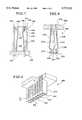
- FIG. 5is a perspective view of the recess cover used with the potting box of FIG. 4;
- FIG. 6is another enlarged perspective view of the potting box of FIG. 4;
- FIG. 7is an enlarged cut-away side view of the female ribbon style connector taken along line 7--7 of FIG. 1;
- FIG. 8is an enlarged perspective view, along with a partial fragmentary view, of a resilient male ribbon style connector for use with the optoelectronic transceiver module of FIGS. 1-3;
- FIG. 9is a cut-away side view of the resilient male ribbon style connector taken along line 9--9 of FIG. 8.
- the module 10has a main housing 12 which generally has the shape of an oblong box.
- the main housing 12has a generally rectangular top 14 with a first end 16 and an opposite second end 18 extending perpendicularly from the top. Attached to the first end 16 of the main housing 12 is a transceiver connector 20 for receiving fiber optic plugs.
- FIG. 2a front view of the optoelectronic transceiver module 10 is depicted.
- the transceiver connector 20is attached to the first end 16 of the main housing 12 by two screws 22,24.
- the two screws 22,24extend through the transceiver connector's mounting ears 26,28 and into the main housing 12.
- Extending perpendicularly from the mounting ears 26,28is a generally rectangularly shaped connector shell 30.
- the connector shell 30provides two receptacles 32,34 for receiving fiber optic connector plugs.
- the receptacles 32,34are formed by the connector shell 30 along with a divider wall 36 which extends along the center of the connector shell.
- a keying channel 40,42located in the bottom 38 of each receptacle 32,34 is a keying channel 40,42 which extends toward the first end 16 of the main housing.
- the receptacles 32,34 of the connector shell 30are specifically dimensioned to receive an SC duplex plug. Therefore, the keying channels 40,42 ensure that an SC plug will be inserted so that receptacle 32 will only accept a plug for sending data and receptacle 34 will only accept a plug for receiving data.
- each optical subassembly 44,46Extending from the main housing 12 and into each of the receptacles 32,34 is an optical subassembly 44,46.
- the optical subassembly 44is for sending transmissions over a data link and the optical subassembly 46 is for receiving transmissions over a data link.
- each optical subassemblyhas a ferrule receiving portion 48,50.
- the ferrule receiving portion 48,50couples with the SC plug.
- the transceiver's latch members 52,54,56, and 58firmly hold the SC plug in contact with connector 20.
- the actual sending and receiving of optically encoded datais performed by a laser diode within the optical subassembly 44 and a photo diode within the optical subassembly 46. Both the laser diode and the photo diode are electrically connected to a circuit board which is mounted within the main housing 12.
- circuit board 60Incorporated onto the circuit board 60 is circuitry for transmitting and receiving optically encoded data (circuitry not shown).
- the circuit board 60is encased in potting material 62 and a potting box 64 which forms the main housing 12.
- the potting material 62encases the circuit board 60 such that only the circuit board's male ribbon style connector 66 extends from the potting material 62.
- FIG. 3a perspective view of the bottom 68 of the transceiver module 10 is depicted.
- the bottom 68has two mounting ports 70,70 which are adjacent to the first end 16 of the main housing 12.
- the male ribbon style connector 66protrudes perpendicularly from the bottom 68 and is adjacent to the second end 18 of the main housing 12.
- the ribbon style connector 66may protrude perpendicularly from the second end 18 of the module 10 so that it can be connected to a circuit card assembly in a direction which is parallel to the direction of insertion of the optic plugs into the module's receptacles.
- another recess coverwill be needed in order to prevent potting material from escaping the second end of the potting box.
- FIG. 4an enlarged perspective view of the optoelectronic module's potting box 64 is depicted.
- the potting box 64forms the outer housing of the optoelectronic module.
- the potting boxgenerally has the shape of an oblong box with a rectangular bottom 72, two parallel side walls 74,74, a first end wall 76, and an opposite second end wall 78.
- the potting box 64is injection molded of a polymer material such as VALOX, STANYL, or any other glass-filled heat resistent material which can withstand solder reflow temperatures. The use of such a potting box eliminates the need for a silicone mold required by prior art modules.
- the potting box 64be either plated, wet plated, or vacuum metalizied with an aluminum or stainless steel coating in order to dissipate an electrostatic discharge and provide for electromagnetic shielding.
- the transceiver connector 20may be plated, wet plated, or vacuum metalized, in order to reduce emissions and enhance grounding of the module.
- Such metalization of the connector 20can bring the module in compliance with FCC Rules, Part 15.
- the connector 20is metalized separately from the potting box 64 so that each attachment portion is metalized and provides for conductivity between the parts.
- the connector 20will be attached to a chassis containing fiber optic connectors which are at ground potential, the connector will ground the metalized potting box 64 which is attached to a daughter board.
- groundingenhances the module's ability to dissipate electrostatic discharge and provide for electromagnetic shielding.
- the transceiver connector 20also includes a grounding clip 25 attached at the slot 23.
- the transceiver's latch members 52, 54, 56, and 58extend from the first wall 76 of the potting box 64. Also, the first end wall 76 of the potting box furnishes the mounting ports 70,70 which are located on the bottom of the main housing. In a preferred embodiment, the latch members 52, 54, 56 and 58 are integrally molded with the potting box 64.
- Circuit board standoff columns 80are also provided by the potting box 64 (only one standoff column is depicted in FIG. 4). Each standoff column protrudes from the bottom 72 of the potting box 64 and is positioned next to the first end wall 76 and one of the side walls 74,74 for supporting the circuit board 60.
- the standoff columns 80have a length equal to approximately half the depth of the potting box 64 with the distal end of the column having a circuit board mounting port 82.
- the first wall 76 of the potting box 64has a recess 84 for allowing the placement of the circuit board's optical subassemblies.
- the recess 84has two semicircular through-ports 86,86. Within each through-port 86,86 are two guide beams 88,90 which are positioned on each end of the through-port's semicircle for positioning the optical subassemblies 44,46.
- the alignment guide beams 92,94boarder each side of the recess 84 and extend along the entire depth of the recess.
- the bottom of the recess 84has three flat mating surfaces 95 (only two of the mating surfaces are depicted in FIG. 4).
- a recess cover 96is depicted for placement within the recess located in the first wall of the potting box.
- the recess cover 96is made of the same material as the potting box and is either plated, wet plated, or vacuum metalizied with an aluminum or stainless steel coating.
- the recess cover 96has two semicircular through-ports 98,100. Within each of the through-ports 98,100 are two guide beams 102,104 positioned on each end of the through-port's semicircle. Also, the top of the recess cover includes three flat mating surfaces 105.
- the recess cover 96firmly mounts within the recess of the potting box's first wall so that the mating surfaces 95 and 105 of both the recess 84 and the recess cover 96 will abut each other.
- the recess cover 96includes three indentions 106 which allow the cover to be positioned around the location where the latch members 52, 54, 56, and 58 attach to the potting box.
- alignment grooves 108, 110which provide for sliding engagement with the alignment guide beams 92,94 bordering the recess within the potting box's first wall.
- the circuit boardis placed in the potting box 64 with the male ribbon connector protruding outside of the potting box and the circuit board's optical subassemblies protruding out of the recess 84 in the first wall 76.
- the optical subassemblies 44,46are properly positioned within the potting box 64 by the alignment guides 88,90 located within each through-port 86,86.
- the circuit board 60is affixed by two screws which are mounted to the standoff columns 80 via the circuit board mounting ports 82.
- the recess cover 96is mounted onto the first end wall 76.
- the recess cover 96is mounted by engaging its alignment grooves 108,110 with the potting box's recess cover alignment guide beams 92,94.
- the cover's through-ports 98,100 and associated alignment guide beams 102,104will adjoin the circuit board's optical subassemblies 44,46.
- a liquid tight sealwill be formed between the potting box 64, the recess cover 96, and the optical subassemblies 44,46.
- the connector shell 20(See FIGS. 1 & 2) is mounted onto the first end wall 76 of the potting box 64 after the potting material has cured. Alignment of the connector shell 20 is provided by two mounting posts 112,112. Each mounting post 112 has a bore 114 which facilitates the attachment of the connector shell 20, by the use of the previously mentioned screws, onto the potting box 64.
- the ribbon style connector 66may protrude perpendicularly from the second end 18 of the module 10 so that it can be connected to a circuit card assembly in a direction which is parallel to the direction of insertion of the optic plugs into the module's receptacles.
- another recess coverwill be needed in order to prevent potting material from escaping the second end of the potting box.
- the male ribbon style connector 66 protruding from the module 10has a beam portion 116, made of insulative material, which extends perpendicularly across the length of the circuit board 60.
- the male ribbon style connector 66also has a first side 118, an opposite second side 120, and a distal end 122. Extending perpendicularly from the circuit board 60 on both the first side 118 and the second side 120 of the male ribbon style connector 66 are twenty-eight electrical contacts 124.
- Each electrical contact 124consists of a strip of conductive material which is affixed to the male ribbon style connector 66 and is electrically connected to the circuitry mounted on the circuit board 60.
- the male ribbon style connector 66couples to a female ribbon style connector 126 which is mounted onto the circuit card assembly 128.
- FIG. 7an enlarged cut-away side view is shown of the female ribbon style connector 126 taken along line 7--7 of FIG. 1.
- the female ribbon style connector 126has two parallel rows of twenty-eight (28) contact beams 130,130 contained within a contact chamber 132 (only one contact from each row is depicted).
- Each contact beam 130is constructed of a flat strip of conductive metallic material.
- each contact beam 130has a first end 134, a second distal end 136, and a bend 138 which is located adjacent to the second end and extends toward the contact beam located in the opposite row.
- the female ribbon style connector 126is mounted onto the circuit card 128 such that the first end 134 of each contact beam 130 extends through the circuit card assembly. Likewise, the second end 136 of each contact beam 130 extends within a travel limitation slot 140 formed in the top 142 of the female ribbon style connector 126. Each slot 140 provides a backstop 144, consisting of one of the connector's walls 146, and a frontstop 148. Correspondingly, contact beams 130,130 are positioned in the chamber 132 such that the second end 136 of each contact beam 130 resiliently urges against the frontstop 148.
- the top 142 of the connectorhas a slot 150 positioned between the two rows of contact beams.
- the distal end 122 of the male ribbon style connectoris inserted within the female connector's slot 150.
- each contact beam 130will resiliently urge against a corresponding electrical contact 124 mounted on the male ribbon style connector 66.
- the male connector 66is simply pulled from the chamber 132 of the female connector. Once the male ribbon style connector 66 has been removed from the chamber 132, the contact beams 130 of the female connector 126 will resiliently regain the configuration of FIG. 7, whereby the second end 136 of each contact beam will abut its corresponding frontstop 148.
- FIG. 8an enlarged perspective view, along with a partial fragmentary view, is depicted of a resilient male ribbon style connector 166.
- the connector 166includes a beam type housing 216 having a first side 218, an opposite second side 220, and a distal end 222.
- the resilient male ribbon style connector 166 in FIG. 8serves as another embodiment of the male ribbon style connector depicted in FIGS. 1-3 wherein the male connector in FIG. 8 is resilient and the male connector in FIGS. 1-3 is non-resilient. It should be noted, however, that other means for quickly installing and replacing the module from a circuit card assembly may be used.
- each contact beam 230is constructed of a flat strip of conductive metallic material. Furthermore, each contact beam 230 has a first end 234, a second distal end 236, and a bend 238 which is located adjacent to the second end and extends away from the contact beam located in the opposite row.
- the male ribbon style connector 166is mounted onto the module's circuit board 260 such that the first end 234 of each contact beam 230 extends through the circuit board.
- the first end 234 of the contact 230is inserted within a through-hole of the circuit board 260 which contains traces for providing an electrical connection from the contact 260 to components mounted on the board.
- the second end 236 of each contact beam 230extends within a travel limitation slot 240 formed in the top 242 of the resilient male ribbon style connector 166.
- Each slot 240provides a backstop 244, consisting of the connector's support wall 246, and a frontstop 248.
- contact beams 230,230are positioned such that the second end 236 of each contact beam 230 resiliently urges against the frontstop 248.
- Access for making an electrical connection with the contact beams 230,230is provided since they protrude from the male ribbon style connector 166 in the area around the bends 238,238.
- the distal end 222 of the male ribbon style connectoris inserted within a slot provided by the female connector.
- the two rows of contact beams 230,230will be forced to compress towards each other.
- each contact beam 230will resiliently urge against a corresponding electrical contact mounted within the female ribbon style connector.
- an electrical connectionwill be formed between the male ribbon style connector's electrical contact beams 230,230 and the female connector's contact beams.
- the male connectoris simply pulled from the female connector.
- the contact beams 230,230will resiliently regain the configuration of FIG. 9, whereby the second end 236 of each contact beam will abut its corresponding frontstop 248.
- top and bottom portions of the transceiver module and its respective potting box componentsare used by way of example only due to the orientation of the drawings. It should also be understood that various changes and modifications to the presently preferred embodiments described herein will be apparent to those skilled in the art.
- the transceiver module depicted in the presently preferred embodimenthas its male ribbon style connector extending from the bottom, it should be understood from the outset that the connector can be configured to extend, for example, from the second end of the transceiver. Therefore, changes and modifications may be made without departing from the spirit and scope of the present invention and without diminishing its attendant advantages. Thus, it is intended that such changes and modifications be covered by the appended claims.
Landscapes
- Physics & Mathematics (AREA)
- General Physics & Mathematics (AREA)
- Optics & Photonics (AREA)
- Electromagnetism (AREA)
- Optical Couplings Of Light Guides (AREA)
Abstract
Description
Claims (12)
Priority Applications (16)
| Application Number | Priority Date | Filing Date | Title |
|---|---|---|---|
| US08/417,914US5717533A (en) | 1995-01-13 | 1995-04-06 | Removable optoelectronic module |
| TW084103710ATW294863B (en) | 1995-01-13 | 1995-04-15 | |
| US08/485,310US5734558A (en) | 1995-01-13 | 1995-06-07 | Removable optoelectronic module |
| US08/538,897US5864468A (en) | 1995-01-13 | 1995-10-04 | Removable optoelectronic module with grounding means |
| GB9525323AGB2297007B (en) | 1995-01-13 | 1995-12-12 | Removable transceiver module and receptacle |
| DE19601949ADE19601949B4 (en) | 1995-01-13 | 1996-01-10 | System for providing static discharge and electromagnetic shielding |
| DE19655315.6ADE19655315B4 (en) | 1995-01-13 | 1996-01-10 | Removable transmitter / receiver module and recording |
| SG9905134ASG101415A1 (en) | 1995-01-13 | 1996-01-12 | Removable tranceiver module and receptacle |
| JP8005170AJP3002691B2 (en) | 1995-01-13 | 1996-01-16 | Transceiver module and receptacle assembly |
| US08/872,319US6201704B1 (en) | 1995-01-13 | 1997-06-10 | Transceive module with EMI shielding |
| US08/954,679US5879173A (en) | 1995-01-13 | 1997-10-17 | Removable transceiver module and receptacle |
| US09/295,743US6267606B1 (en) | 1995-01-13 | 1999-04-20 | Removable transceiver module and receptacle |
| JP11124468AJP2000040562A (en) | 1995-01-13 | 1999-04-30 | Transceiver module and receptacle assembly |
| US09/920,421US6551117B2 (en) | 1995-01-13 | 2001-08-01 | Removable transceiver module |
| US10/154,658US20020142634A1 (en) | 1995-01-13 | 2002-05-24 | Removable transceiver module and receptacle |
| US10/734,863US20040127102A1 (en) | 1995-01-13 | 2003-12-12 | Removable transceiver module and receptacle |
Applications Claiming Priority (2)
| Application Number | Priority Date | Filing Date | Title |
|---|---|---|---|
| US08/372,780US5546281A (en) | 1995-01-13 | 1995-01-13 | Removable optoelectronic transceiver module with potting box |
| US08/417,914US5717533A (en) | 1995-01-13 | 1995-04-06 | Removable optoelectronic module |
Related Parent Applications (1)
| Application Number | Title | Priority Date | Filing Date |
|---|---|---|---|
| US08/372,780Continuation-In-PartUS5546281A (en) | 1995-01-13 | 1995-01-13 | Removable optoelectronic transceiver module with potting box |
Related Child Applications (4)
| Application Number | Title | Priority Date | Filing Date |
|---|---|---|---|
| US08/485,310Continuation-In-PartUS5734558A (en) | 1995-01-13 | 1995-06-07 | Removable optoelectronic module |
| US51581395AContinuation-In-Part | 1995-01-13 | 1995-08-16 | |
| US08/538,897Continuation-In-PartUS5864468A (en) | 1995-01-13 | 1995-10-04 | Removable optoelectronic module with grounding means |
| US08/872,319ContinuationUS6201704B1 (en) | 1995-01-13 | 1997-06-10 | Transceive module with EMI shielding |
Publications (1)
| Publication Number | Publication Date |
|---|---|
| US5717533Atrue US5717533A (en) | 1998-02-10 |
Family
ID=27005912
Family Applications (2)
| Application Number | Title | Priority Date | Filing Date |
|---|---|---|---|
| US08/417,914Expired - LifetimeUS5717533A (en) | 1995-01-13 | 1995-04-06 | Removable optoelectronic module |
| US08/872,319Expired - LifetimeUS6201704B1 (en) | 1995-01-13 | 1997-06-10 | Transceive module with EMI shielding |
Family Applications After (1)
| Application Number | Title | Priority Date | Filing Date |
|---|---|---|---|
| US08/872,319Expired - LifetimeUS6201704B1 (en) | 1995-01-13 | 1997-06-10 | Transceive module with EMI shielding |
Country Status (2)
| Country | Link |
|---|---|
| US (2) | US5717533A (en) |
| TW (1) | TW294863B (en) |
Cited By (72)
| Publication number | Priority date | Publication date | Assignee | Title |
|---|---|---|---|---|
| US6042392A (en)* | 1996-10-28 | 2000-03-28 | Yazaki Corporation | Printed circuit board connector fitting structure |
| USRE36820E (en) | 1995-01-13 | 2000-08-15 | Methode Electronics, Inc. | Removable optoelectronic module |
| US6146150A (en)* | 1998-11-24 | 2000-11-14 | International Business Machines Corporation | Circuit card with separate interfaces for different bus architectures |
| US6179627B1 (en) | 1998-04-22 | 2001-01-30 | Stratos Lightwave, Inc. | High speed interface converter module |
| US6201704B1 (en) | 1995-01-13 | 2001-03-13 | Stratos Lightwave, Inc. | Transceive module with EMI shielding |
| US6203333B1 (en) | 1998-04-22 | 2001-03-20 | Stratos Lightwave, Inc. | High speed interface converter module |
| US6213651B1 (en) | 1999-05-26 | 2001-04-10 | E20 Communications, Inc. | Method and apparatus for vertical board construction of fiber optic transmitters, receivers and transceivers |
| US6217228B1 (en) | 1999-07-14 | 2001-04-17 | Stratos Lightwave, Inc. | Fiber channel drive adapter |
| US6220878B1 (en) | 1995-10-04 | 2001-04-24 | Methode Electronics, Inc. | Optoelectronic module with grounding means |
| US6220873B1 (en) | 1999-08-10 | 2001-04-24 | Stratos Lightwave, Inc. | Modified contact traces for interface converter |
| US20010048793A1 (en)* | 1999-05-27 | 2001-12-06 | Edwin Dair | Method and apparatus for multiboard fiber optic modules and fiber optic module arrays |
| US6350063B1 (en) | 1999-12-13 | 2002-02-26 | Stratos Lightwave, Inc. | Pluggable optical transceiver module having a high speed serial data connector (HSSDC) |
| US20020023853A1 (en)* | 2000-07-31 | 2002-02-28 | Michael Lax | Case with internal lock |
| US20020028048A1 (en)* | 1999-05-27 | 2002-03-07 | Edwin Dair | Method and apparatus for multiboard fiber optic modules and fiber optic module arrays |
| US20020030872A1 (en)* | 1999-05-27 | 2002-03-14 | Edwin Dair | Method and apparatus for multiboard fiber optic modules and fiber optic module arrays |
| US20020033979A1 (en)* | 1999-05-27 | 2002-03-21 | Edwin Dair | Method and apparatus for multiboard fiber optic modules and fiber optic module arrays |
| US20020110338A1 (en)* | 2001-02-12 | 2002-08-15 | Edwin Dair | Fiber-optic modules with shielded housing/covers having mixed finger types |
| US20020110336A1 (en)* | 2001-02-12 | 2002-08-15 | Edwin Dair | Fiber-optic modules with housing/shielding |
| US6464517B1 (en)* | 2001-11-27 | 2002-10-15 | Hon Hai Precision Ind. Co., Ltd. | GBIC having spring-mounted shielding door |
| US20020150344A1 (en)* | 2001-04-14 | 2002-10-17 | Chiu Liew C. | Pull-action de-latching mechanisms for fiber optic modules |
| US6494623B1 (en) | 2001-08-09 | 2002-12-17 | Infineon Technologies Ag | Release mechanism for pluggable fiber optic transceiver |
| US20030000856A1 (en)* | 2001-06-27 | 2003-01-02 | Autronic Plastics, Inc. | Storage case |
| US20030020986A1 (en)* | 1999-05-27 | 2003-01-30 | Pang Ron Cheng Chuan | Method and apparatus for pluggable fiber optic modules |
| US6570768B2 (en) | 2000-11-30 | 2003-05-27 | Stratos Lightwave | Pluggable transceiver module with extended release and removal lever |
| US20030111367A1 (en)* | 2000-10-25 | 2003-06-19 | Michael Lax | Storage case |
| US20030133667A1 (en)* | 2001-04-14 | 2003-07-17 | E2O Communications, Inc. | De-latching mechanisms for fiber optic modules |
| US6632030B2 (en) | 1999-05-27 | 2003-10-14 | E20 Communications, Inc. | Light bending optical block for fiber optic modules |
| US20040033027A1 (en)* | 2001-04-14 | 2004-02-19 | Pang Ron Cheng Chuan | Cam-follower release mechanism for fiber optic modules with side delatching mechanisms |
| US20040069997A1 (en)* | 1999-05-27 | 2004-04-15 | Edwin Dair | Method and apparatus for multiboard fiber optic modules and fiber optic module arrays |
| US20040129587A1 (en)* | 2003-02-07 | 2004-07-08 | Lax Michael R. | Lockable container having an integral and internal locking mechanism and methods of use |
| US20040156598A1 (en)* | 2003-01-29 | 2004-08-12 | Delta Electronics, Inc. | Pluggable optical transceiver module |
| US6780053B1 (en) | 2000-08-09 | 2004-08-24 | Picolight Incorporated | Pluggable small form factor transceivers |
| US6789958B2 (en) | 2001-08-31 | 2004-09-14 | Infineon Technologies Ag | Release mechanism for pluggable fiber optic transceiver |
| US20040185696A1 (en)* | 2003-03-22 | 2004-09-23 | Tyco Electronics Corporation | Push button de-latch mechanism for pluggable electronic module |
| US20040188286A1 (en)* | 2003-03-26 | 2004-09-30 | Autronic Plastics, Inc. | Benefit denial systems for securing an asset within a container and methods of use |
| US20040259870A1 (en)* | 2003-03-25 | 2004-12-23 | Syrrx, Inc. | Dipeptidyl peptidase inhibitors |
| US6840680B1 (en) | 2001-04-14 | 2005-01-11 | Jds Uniphase Corporation | Retention and release mechanisms for fiber optic modules |
| US6846115B1 (en) | 2001-01-29 | 2005-01-25 | Jds Uniphase Corporation | Methods, apparatus, and systems of fiber optic modules, elastomeric connections, and retention mechanisms therefor |
| US20050019973A1 (en)* | 2003-07-23 | 2005-01-27 | Palo Alto Research Center, Incorporated | Phase array oxide-confined VCSEL |
| US6863448B2 (en) | 2001-04-14 | 2005-03-08 | Jds Uniphase Corporation | Method and apparatus for push button release fiber optic modules |
| US6873800B1 (en) | 1999-05-26 | 2005-03-29 | Jds Uniphase Corporation | Hot pluggable optical transceiver in a small form pluggable package |
| US6901221B1 (en) | 1999-05-27 | 2005-05-31 | Jds Uniphase Corporation | Method and apparatus for improved optical elements for vertical PCB fiber optic modules |
| US20050158902A1 (en)* | 1997-02-07 | 2005-07-21 | Xerox Corporation | Method and structure for eliminating polarization instability in laterally - oxidized VCSELs |
| US6942395B1 (en) | 2001-01-29 | 2005-09-13 | Jds Uniphase Corporation | Method and apparatus of pull-lever release for fiber optic modules |
| US20050271396A1 (en)* | 2004-03-19 | 2005-12-08 | John Iannelli | Directly modulated laser optical transmission system |
| US20050271333A1 (en)* | 2004-06-04 | 2005-12-08 | Industrial Technology Research Institute | Light transceiver module |
| US20060018583A1 (en)* | 2004-05-05 | 2006-01-26 | Iannelli John M | Method and apparatus for distortion control for optical transmitters |
| US20060023434A1 (en)* | 2004-07-31 | 2006-02-02 | Bogdan Andrei | Latch system |
| US6994478B1 (en) | 2001-04-14 | 2006-02-07 | Jds Uniphase Corporation | Modules having rotatable release and removal lever |
| US20060029332A1 (en)* | 2002-08-09 | 2006-02-09 | Jds Uniphase Corporation | Retention and release mechanisms for fiber optic modules |
| US20060042330A1 (en)* | 1999-11-02 | 2006-03-02 | Autronic Plastics, Inc. | Storage case locking member |
| US7013088B1 (en) | 1999-05-26 | 2006-03-14 | Jds Uniphase Corporation | Method and apparatus for parallel optical interconnection of fiber optic transmitters, receivers and transceivers |
| US20060088251A1 (en)* | 2004-10-15 | 2006-04-27 | Xiaozhong Wang | Integrated optical fiber and electro-optical converter |
| US20060108252A1 (en)* | 2004-10-11 | 2006-05-25 | Lax Michael R | Lockable container with merchandising features |
| US20060116899A1 (en)* | 2003-02-10 | 2006-06-01 | R Lax Michael | Apparatus and methods for processing items |
| US7090509B1 (en) | 1999-06-11 | 2006-08-15 | Stratos International, Inc. | Multi-port pluggable transceiver (MPPT) with multiple LC duplex optical receptacles |
| US20060210282A1 (en)* | 2005-03-15 | 2006-09-21 | John Iannelli | Directly modulated laser optical transmission system with phase modulation |
| US20060222004A1 (en)* | 2005-04-01 | 2006-10-05 | International Business Machines Corporation | Methods and apparatus for transferring data |
| US20070081310A1 (en)* | 2005-09-23 | 2007-04-12 | Kowalkowski Anthony S | Cageless, pluggable optoelectronic device |
| US20070117458A1 (en)* | 2005-11-18 | 2007-05-24 | Picolight Incorporated | Pluggable module and cage |
| USD544743S1 (en) | 2005-09-26 | 2007-06-19 | Autronic Plastics, Inc. | Media storage case |
| US20070206962A1 (en)* | 2006-03-02 | 2007-09-06 | Emcore Corporation | Externally modulated laser optical transmission system with feed forward noise cancellation |
| US20070206961A1 (en)* | 2006-03-02 | 2007-09-06 | Emcore Corporation | Directly modulated or externally modulated laser optical transmission system with feed forward noise cancellation |
| US20070280604A1 (en)* | 2006-05-23 | 2007-12-06 | John Jablonski | Cageless, pluggable optoelectronic device which enables belly-to-belly layouts |
| USRE40150E1 (en) | 1994-04-25 | 2008-03-11 | Matsushita Electric Industrial Co., Ltd. | Fiber optic module |
| US20080170375A1 (en)* | 2007-01-16 | 2008-07-17 | John Jablonski | Optoelectronic device in combination with a push-in cage |
| US20080219304A1 (en)* | 2004-04-02 | 2008-09-11 | Vladimir Kupershmidt | Analog external cavity laser |
| US20090226166A1 (en)* | 2001-02-05 | 2009-09-10 | Aronson Lewis B | Optoelectronic Transceiver with Digital Diagnostics |
| US20090305572A1 (en)* | 2006-11-17 | 2009-12-10 | Nintendo Co., Ltd. | Secure and/or lockable connecting arrangement for video game system |
| US20100002587A1 (en)* | 2008-07-01 | 2010-01-07 | Gayle Loretta Ray Noble | Diagnostics for Serial Communication Busses |
| USRE44647E1 (en) | 2005-03-15 | 2013-12-17 | Emcore Corporation | Directly modulated laser optical transmission system with phase modulation |
| CZ307861B6 (en)* | 2018-04-26 | 2019-07-03 | SQS Vláknová optika a.s. | Plug-in and slide-out device for connecting and disconnecting optical and / or electrical connectors |
Families Citing this family (39)
| Publication number | Priority date | Publication date | Assignee | Title |
|---|---|---|---|---|
| US6583902B1 (en) | 1999-12-09 | 2003-06-24 | Alvesta, Inc. | Modular fiber-optic transceiver |
| JP2001264593A (en)* | 2000-03-22 | 2001-09-26 | Sumitomo Electric Ind Ltd | Optical device |
| JP3534393B2 (en)* | 2000-04-14 | 2004-06-07 | インターナショナル・ビジネス・マシーンズ・コーポレーション | Electrical connection structure of electronic component unit, computer device and electronic device |
| US6624507B1 (en) | 2000-05-09 | 2003-09-23 | National Semiconductor Corporation | Miniature semiconductor package for opto-electronic devices |
| US6642613B1 (en)* | 2000-05-09 | 2003-11-04 | National Semiconductor Corporation | Techniques for joining an opto-electronic module to a semiconductor package |
| US6767140B2 (en)* | 2000-05-09 | 2004-07-27 | National Semiconductor Corporation | Ceramic optical sub-assembly for opto-electronic module utilizing LTCC (low-temperature co-fired ceramic) technology |
| US6497518B1 (en)* | 2000-11-14 | 2002-12-24 | National Semiconductor Corporation | Miniature opto-electronic transceiver |
| US6916121B2 (en) | 2001-08-03 | 2005-07-12 | National Semiconductor Corporation | Optical sub-assembly for optoelectronic modules |
| US6380482B1 (en)* | 2000-08-31 | 2002-04-30 | Avaya Technology Corp. | Electromagnetic compatibility sleeve for electrical interconnections |
| US6797882B1 (en)* | 2000-10-18 | 2004-09-28 | Silicon Bandwidth, Inc. | Die package for connection to a substrate |
| US7101091B2 (en)* | 2001-02-21 | 2006-09-05 | Zarlink Semiconductor, Inc. | Apparatus for coupling a fiber optic cable to an optoelectronic device, a system including the apparatus, and a method of forming the same |
| JP2002286976A (en)* | 2001-03-26 | 2002-10-03 | Auto Network Gijutsu Kenkyusho:Kk | Optical connector device and optical connector |
| US7023705B2 (en) | 2001-08-03 | 2006-04-04 | National Semiconductor Corporation | Ceramic optical sub-assembly for optoelectronic modules |
| US7269027B2 (en)* | 2001-08-03 | 2007-09-11 | National Semiconductor Corporation | Ceramic optical sub-assembly for optoelectronic modules |
| US6973225B2 (en)* | 2001-09-24 | 2005-12-06 | National Semiconductor Corporation | Techniques for attaching rotated photonic devices to an optical sub-assembly in an optoelectronic package |
| US6666589B2 (en) | 2001-11-05 | 2003-12-23 | International Business Machines Corporation | Internal EMI shield for multiple array optoelectronic devices |
| US6634803B2 (en) | 2001-11-05 | 2003-10-21 | International Business Machines Corporation | External EMI shield for multiple array optoelectronic devices |
| US7204648B2 (en)* | 2002-03-19 | 2007-04-17 | Finisar Corporation | Apparatus for enhancing impedance-matching in a high-speed data communications system |
| US6804119B2 (en) | 2002-07-31 | 2004-10-12 | Hewlett-Packard Development Company, L.P. | Method and edge connector providing electrostatic discharge arrest features and digital camera employing same |
| US6822879B2 (en) | 2002-08-06 | 2004-11-23 | Emcore Corporation | Embedded electromagnetic interference shield |
| US7156562B2 (en)* | 2003-07-15 | 2007-01-02 | National Semiconductor Corporation | Opto-electronic module form factor having adjustable optical plane height |
| US6985668B2 (en)* | 2003-07-15 | 2006-01-10 | National Semiconductor Corporation | Multi-purpose optical light pipe |
| US20050013559A1 (en)* | 2003-07-16 | 2005-01-20 | Agilent Technologies, Inc. | Interface adaptor |
| US7172347B1 (en)* | 2004-09-07 | 2007-02-06 | Finisar Corporation | Optoelectronic arrangement with a pluggable optoelectronic module and an electrical connector to be mounted on a host-printed circuit board and electrical connector |
| US7660128B2 (en)* | 2004-09-30 | 2010-02-09 | Emcore Corporation | Apparatus for electrical and optical interconnection |
| US7373031B2 (en)* | 2004-09-30 | 2008-05-13 | Intel Corporation | Apparatus for an electro-optical device connection |
| US7056156B1 (en) | 2004-12-06 | 2006-06-06 | Jds Uniphase Corporation | Vertically offset EMI projections |
| US7355857B2 (en)* | 2006-02-07 | 2008-04-08 | Methode Electronics, Inc. | Heat sink gasket |
| US7733659B2 (en)* | 2006-08-18 | 2010-06-08 | Delphi Technologies, Inc. | Lightweight audio system for automotive applications and method |
| TWI355155B (en)* | 2007-03-21 | 2011-12-21 | Delta Electronics Inc | Optical communicating device |
| JP5200857B2 (en)* | 2008-10-28 | 2013-06-05 | 住友電装株式会社 | Electrical junction box |
| US8053683B2 (en)* | 2009-03-30 | 2011-11-08 | Lockheed Martin Corporation | Equipment container retention and bonding system and method |
| US8803269B2 (en) | 2011-05-05 | 2014-08-12 | Cisco Technology, Inc. | Wafer scale packaging platform for transceivers |
| CN103166052A (en)* | 2011-12-16 | 2013-06-19 | 鸿富锦精密工业(深圳)有限公司 | Connector anti-loosening device |
| CN103178393A (en)* | 2011-12-22 | 2013-06-26 | 鸿富锦精密工业(深圳)有限公司 | Anti-loosening device for connectors |
| US8911158B2 (en) | 2012-07-09 | 2014-12-16 | Avago Technologies General Ip (Singapore) Pte. Ltd. | Z-pluggable optical communications module, an optical communications system, and a method |
| US9304274B2 (en) | 2012-07-09 | 2016-04-05 | Avago Technologies General Ip (Singapore) Pte. Ltd. | Metal strain relief device for use in an optical communications system, an optical fiber cable that employs the strain relief device, and a method |
| US8950954B2 (en) | 2012-07-31 | 2015-02-10 | Avago Technologies General Ip ( Singapore) Pte. Ltd. | Side-edge mountable parallel optical communications module, an optical communications system that incorporates the module, and a method |
| CN109041280A (en) | 2017-06-09 | 2018-12-18 | 捷温股份有限公司 | Heating cushion with the electric control unit for being integrated with connector |
Citations (16)
| Publication number | Priority date | Publication date | Assignee | Title |
|---|---|---|---|---|
| US4176897A (en)* | 1976-11-19 | 1979-12-04 | Bunker Ramo Corporation | EMI protected connector assembly |
| US4380360A (en)* | 1981-06-03 | 1983-04-19 | Amp Incorporated | Cartridge, holder and connector system |
| US4388671A (en)* | 1981-06-29 | 1983-06-14 | Honeywell Information Systems Inc. | Cathode ray tube display terminal having an enclosure for protection of a logic board |
| US4486059A (en)* | 1982-09-20 | 1984-12-04 | Magnetic Controls Company | Receptacle assembly |
| US4652976A (en)* | 1982-09-30 | 1987-03-24 | Canon Kabushiki Kaisha | Electronic equipment |
| EP0228278A2 (en)* | 1985-12-27 | 1987-07-08 | E.I. Du Pont De Nemours And Company | Electrical connector assembly |
| US4720630A (en)* | 1985-04-05 | 1988-01-19 | Hitachi, Ltd. | Active optical connector including an electronic circuit board and an optical fiber |
| US4798430A (en)* | 1987-06-08 | 1989-01-17 | Siemens Ag | Lightwave guide connector with release levers |
| US4811165A (en)* | 1987-12-07 | 1989-03-07 | Motorola, Inc. | Assembly for circuit modules |
| US4849944A (en)* | 1986-08-18 | 1989-07-18 | Tokyo Electric Company, Ltd. | Connecting structure for connecting a memory unit to a memory unit controller |
| US5013247A (en)* | 1989-10-16 | 1991-05-07 | International Business Machines Corporation | Fiber optic connector assembly adapted for providing circuit card charging |
| US5039194A (en)* | 1990-01-09 | 1991-08-13 | International Business Machines Corporation | Optical fiber link card |
| US5202943A (en)* | 1991-10-04 | 1993-04-13 | International Business Machines Corporation | Optoelectronic assembly with alignment member |
| GB2264843A (en)* | 1992-02-28 | 1993-09-08 | Texas Instruments Ltd | An interface device for coupling a host device to a computer network |
| US5345530A (en)* | 1992-05-28 | 1994-09-06 | Motorola, Inc. | Molded waveguide and method for making same |
| EP0652696A1 (en)* | 1993-11-09 | 1995-05-10 | AT&T Corp. | Shielded arrangement |
Family Cites Families (341)
| Publication number | Priority date | Publication date | Assignee | Title |
|---|---|---|---|---|
| US2899669A (en) | 1959-08-11 | Electrical connector | ||
| DE1301186B (en) | 1963-09-19 | 1969-08-14 | Basf Ag | Process for the metallization of surfaces of plastic objects |
| US3264601A (en) | 1964-03-10 | 1966-08-02 | Boeing Co | Electrical connector |
| US3497866A (en) | 1967-01-25 | 1970-02-24 | Hood Gust Irish & Lundy | Electrical connector |
| US3474380A (en) | 1968-02-19 | 1969-10-21 | Edwin A Miller | Electrical connectors |
| US3673545A (en) | 1969-11-10 | 1972-06-27 | Bunker Ramo | Miniature connector construction{13 adjustable or floating |
| US3670290A (en) | 1971-04-21 | 1972-06-13 | Wilhelm Angele | Electrical connector |
| US3737729A (en) | 1971-06-14 | 1973-06-05 | Zeltex Inc | Electronic package and method of construction |
| DE2204559A1 (en) | 1972-02-01 | 1973-08-09 | Franckh Sche Verlagshandlung W | BUILDING PLATE FOR CONSTRUCTION OF ELECTRICAL AND ELECTRONIC CIRCUITS |
| US3792284A (en) | 1972-10-13 | 1974-02-12 | Gte Sylvania Inc | Electro-optic transmission link |
| US3809908A (en) | 1973-06-29 | 1974-05-07 | Itt | Electro-optical transmission line |
| FR2262407B1 (en) | 1974-02-22 | 1977-09-16 | Radiotechnique Compelec | |
| US4156903A (en) | 1974-02-28 | 1979-05-29 | Burroughs Corporation | Data driven digital data processor |
| US4369494A (en) | 1974-12-09 | 1983-01-18 | Compagnie Honeywell Bull | Apparatus and method for providing synchronization between processes and events occurring at different times in a data processing system |
| US4427879A (en) | 1975-04-18 | 1984-01-24 | Allied Corporation | Optoelectronic connector assembly |
| US3990761A (en) | 1975-08-11 | 1976-11-09 | Gte Sylvania Incorporated | Zero force connector assembly |
| CA1080307A (en) | 1976-01-29 | 1980-06-24 | Andrew E. Deczky | Optical telemetry for aluminium reduction plant bridge cranes |
| US4217019A (en) | 1976-11-19 | 1980-08-12 | Bunker Ramo Corporation | EMI protected connector assembly |
| US4217488A (en) | 1977-01-21 | 1980-08-12 | Bell Telephone Laboratories, Incorporated | Secure optical communication components, method, and system |
| IT1094110B (en) | 1977-04-29 | 1985-07-26 | Rau Swf Autozubehoer | FASTENING DEVICE FOR SWITCHES |
| US4149072A (en) | 1977-08-05 | 1979-04-10 | Minnesota Mining And Manufacturing Company | System for flat ribbon optical fiber data communications link |
| FR2410884A1 (en) | 1977-11-30 | 1979-06-29 | Thomson Csf | CONNECTION DEVICE TO AN OPTICAL BUS LINE AND BUS LINE INCLUDING SUCH A DEVICE |
| US4161650A (en) | 1978-04-06 | 1979-07-17 | Lockheed Aircraft Corporation | Self-powered fiber optic interconnect system |
| US4399563A (en) | 1978-04-18 | 1983-08-16 | Honeywell Information Systems Inc. | Fiber optics high speed modem |
| JPS5818299Y2 (en) | 1978-04-28 | 1983-04-13 | 富士通株式会社 | Electronic equipment with built-in printed circuit board unit |
| US4234968A (en) | 1978-09-05 | 1980-11-18 | Ncr Corporation | Optical coupler module in a distributed processing system |
| US4347655A (en) | 1978-09-28 | 1982-09-07 | Optical Information Systems, Inc. | Mounting arrangement for semiconductor optoelectronic devices |
| GB2055196B (en) | 1978-11-08 | 1983-03-30 | Rozenwaig Boris | Tches comprising such device signal switching device through optical means and self swi |
| US4268756A (en) | 1978-11-13 | 1981-05-19 | Trw Inc. | Optical transceiver |
| US4295181A (en) | 1979-01-15 | 1981-10-13 | Texas Instruments Incorporated | Module for an integrated circuit system |
| US4273413A (en) | 1979-02-26 | 1981-06-16 | Amp Incorporated | Photoelectric element/optical cable connector |
| US4393516A (en) | 1979-03-09 | 1983-07-12 | Electric Power Research Institute, Inc. | Data transmission system and method |
| US4276656A (en) | 1979-03-19 | 1981-06-30 | Honeywell Information Systems Inc. | Apparatus and method for replacement of a parallel, computer-to-peripheral wire link with a serial optical link |
| US4257124A (en) | 1979-04-02 | 1981-03-17 | The Boeing Company | Optical repeater for use in active multiport fiber optic data bus coupler |
| US4360248A (en) | 1979-04-18 | 1982-11-23 | International Telephone And Telegraph Corporation | Multiport optical communication system and optical star structure therefor |
| GB2056661A (en) | 1979-08-16 | 1981-03-18 | Cossor Ltd A C | Telemetry system |
| US4249266A (en) | 1979-11-06 | 1981-02-03 | Perkins Research & Mfg. Co., Inc. | Fiber optics communication system |
| DE3001638A1 (en) | 1980-01-17 | 1981-07-23 | Siemens AG, 1000 Berlin und 8000 München | PASSIVE BUS SYSTEM FOR DECENTRALLY STRUCTURED MULTIPLE COMPUTER ARRANGEMENTS, IN PARTICULAR MULTIMICRO COMPUTER ARRANGEMENTS |
| US4531810A (en) | 1980-01-17 | 1985-07-30 | Gte Laboratories Incorporated | Optical fiber holders |
| FR2476349A1 (en) | 1980-02-15 | 1981-08-21 | Philips Ind Commerciale | DISTRIBUTED DATA PROCESSING SYSTEM |
| US4301543A (en) | 1980-02-20 | 1981-11-17 | General Dynamics Corporation, Pomona Division | Fiber optic transceiver and full duplex point-to-point data link |
| US4408273A (en) | 1980-05-27 | 1983-10-04 | International Business Machines Corporation | Method and means for cataloging data sets using dual keyed data sets and direct pointers |
| US4366565A (en) | 1980-07-29 | 1982-12-28 | Herskowitz Gerald J | Local area network optical fiber data communication |
| US4330870A (en) | 1980-09-05 | 1982-05-18 | Datapoint Corporation | Optical data link |
| SE421150B (en) | 1980-09-17 | 1981-11-30 | John Ivan Fridolf Rogstadius | PROCEDURE FOR ASTADCOM A CLEAR CONCENTRIC FIXING OF AN OPTICAL FIBER IN A PROP |
| US4345808A (en) | 1980-11-20 | 1982-08-24 | International Telephone And Telegraph Corporation | Electrical connector |
| US4539476A (en) | 1980-11-28 | 1985-09-03 | Tokyo Shibaura Denki Kabushiki Kaisha | Module for a fiber optic link |
| JPS57104339A (en) | 1980-12-19 | 1982-06-29 | Ricoh Co Ltd | Optical communication network |
| CH651972A5 (en) | 1981-03-05 | 1985-10-15 | Bbc Brown Boveri & Cie | Power distribution system. |
| DE3112939A1 (en) | 1981-03-31 | 1982-10-07 | Siemens AG, 1000 Berlin und 8000 München | PRISM COUPLER FOR IN AND / OR OUT COUPLING RADIATION IN OR FROM AN OPTICAL WAVE GUIDE |
| US4453903A (en) | 1981-04-15 | 1984-06-12 | North American Philips Corporation | Insert molding gate design for encapsulating electronic ceramics with thermoplastic materials |
| DE3171379D1 (en) | 1981-04-28 | 1985-08-22 | Ibm | Bus arrangement for interconnectiong circuit chips |
| US4439006A (en) | 1981-05-18 | 1984-03-27 | Motorola, Inc. | Low cost electro-optical connector |
| DE3123448A1 (en) | 1981-06-12 | 1982-12-30 | Siemens AG, 1000 Berlin und 8000 München | ARRANGEMENT FOR CONTROLLING THE BUS ACCESS OF A VARIETY OF DEVICES USING A BUS IN A NETWORK CONSTRUCTED WITH AT LEAST ONE OPTICAL MIXER AS A PASSIVE BUS SYSTEM, ESPECIALLY FOR MULTIPLE COMPUTER SYSTEMS |
| FR2512216A1 (en) | 1981-08-26 | 1983-03-04 | Cables De Lyon Geoffroy Delore | CABLE CONNECTING DEVICE COMPRISING OPTICAL FIBERS AND METAL CONDUCTORS |
| DE3138895A1 (en) | 1981-09-30 | 1983-04-14 | Siemens AG, 1000 Berlin und 8000 München | COUPLING ELEMENT FOR IN OR OUT COUPLING LIGHT OUTPUT IN OR FROM A LIGHT GUIDE |
| FR2515222A1 (en) | 1981-10-27 | 1983-04-29 | Telecommunications Sa | DEVICE FOR PREPARING THE NAPPERS OF OPTICAL FIBER EXTENSIONS AROUND A STRUCTURE WITH AN AXIAL SYMMETRY |
| FR2515364B1 (en) | 1981-10-28 | 1985-07-05 | Cables De Lyon Geoffroy Delore | DEVICE FOR REINFORCING THE END WELDING OF TWO OPTICAL FIBERS |
| DE3142918A1 (en) | 1981-10-29 | 1983-05-11 | Licentia Patent-Verwaltungs-Gmbh, 6000 Frankfurt | OPTO-ELECTRICAL COUPLING |
| US4556279A (en) | 1981-11-09 | 1985-12-03 | Board Of Trustees Of The Leland Stanford Junior University | Passive fiber optic multiplexer |
| US4511207A (en) | 1981-11-19 | 1985-04-16 | The Board Of Trustees Of The Leland Stanford Junior University | Fiber optic data distributor |
| JPS5897015A (en) | 1981-12-05 | 1983-06-09 | Kokusai Denshin Denwa Co Ltd <Kdd> | Watertight optical fiber connector |
| US4461537A (en) | 1981-12-24 | 1984-07-24 | Molex Incorporated | Fiber optic connector assembly |
| DE3201240C2 (en) | 1982-01-16 | 1984-05-10 | Schiederwerk Günter Schmidt KG Fabrik für Apparate der Fernmelde- und Elektrotechnik, 8500 Nürnberg | Device for the detachable connection of optical waveguide fibers |
| US4573760A (en) | 1982-01-19 | 1986-03-04 | Fan Robert J | Connector system for a single optical fiber |
| US4535233A (en) | 1982-01-22 | 1985-08-13 | Digital Equipment Corporation | Bootstrap-transimpedance preamplifier for a fiber optic receiver |
| DE3203929A1 (en) | 1982-02-05 | 1983-08-11 | Siemens AG, 1000 Berlin und 8000 München | DETACHABLE COUPLING FOR LIGHT GUIDE |
| US4459658A (en) | 1982-02-26 | 1984-07-10 | Bell Telephone Laboratories Incorporated | Technique for enabling operation of a computer system with a consistent state of a linked list data structure after a main memory failure |
| US4519670A (en) | 1982-03-02 | 1985-05-28 | Spinner Gmbh, Elektrotechnische Fabrik | Light-rotation coupling for a plurality of channels |
| US4569569A (en) | 1982-03-31 | 1986-02-11 | Plessey Overseas Limited | Optical coupling devices |
| FR2524987A1 (en) | 1982-04-09 | 1983-10-14 | Cables De Lyon Geoffroy Delore | DEVICE FOR CONNECTING THE END OF TWO FIBER OPTIC SUBMARINE CABLES AND METHOD OF MANUFACTURING THE SAME |
| US4544234A (en) | 1982-04-09 | 1985-10-01 | At&T Bell Laboratories | Low loss optical fiber splicing |
| GB2121975B (en) | 1982-04-28 | 1985-07-17 | Barr & Stroud Ltd | Optical communications |
| US4432604A (en) | 1982-04-28 | 1984-02-21 | Bell Telephone Laboratories, Incorporated | Self-adjusting fiberoptic connector assembly |
| US4550975A (en) | 1982-04-29 | 1985-11-05 | At&T Bell Laboratories | Optical coupling devices |
| US4501021A (en) | 1982-05-03 | 1985-02-19 | General Signal Corporation | Fiber optic data highway |
| US4530566A (en) | 1982-05-12 | 1985-07-23 | Bicc Public Limited Company | Optical fiber duplex coupler |
| US4534616A (en) | 1982-05-24 | 1985-08-13 | Amp Incorporated | Fiber optic connector having lens |
| DE3229571A1 (en) | 1982-08-07 | 1984-02-09 | Philips Kommunikations Industrie AG, 8500 Nürnberg | OPTICAL STAR COUPLER |
| US4514586A (en)* | 1982-08-30 | 1985-04-30 | Enthone, Inc. | Method of using a shielding means to attenuate electromagnetic radiation in the radio frequency range |
| US4563057A (en) | 1982-08-31 | 1986-01-07 | The United States Of America As Represented By The Secretary Of The Air Force | Fiber optic cable connector |
| US4588256A (en) | 1982-09-07 | 1986-05-13 | Minnesota Mining And Manufacturing Company | Optical fiber connector |
| US4493113A (en) | 1982-09-10 | 1985-01-08 | At&T Bell Laboratories | Bidirectional fiber optic transmission systems and photodiodes for use in such systems |
| FR2533322B1 (en) | 1982-09-17 | 1985-01-25 | Telecommunications Sa | OPTICAL FIBER END CONNECTION DEVICE |
| GB2127990B (en) | 1982-09-29 | 1986-05-14 | Gen Electric Co Plc | Coupling optical fibre and opto-electronic device |
| US4595839A (en) | 1982-09-30 | 1986-06-17 | Tetra-Tech, Inc. | Bidirectional optical electronic converting connector with integral preamplification |
| US4545074A (en) | 1982-10-22 | 1985-10-01 | International Business Machines Corporation | Fiber optic loop system with bypass mode |
| JPS5977402A (en) | 1982-10-26 | 1984-05-02 | Toshiba Corp | optical link |
| US4545077A (en) | 1982-10-29 | 1985-10-01 | Lockheed Corporation | Electro-optical data bus |
| DE3243595C2 (en) | 1982-11-25 | 1985-10-17 | Smit Transformatoren B.V., Nijmegen | Winding arrangement for a gas-cooled transformer |
| US4597631A (en) | 1982-12-02 | 1986-07-01 | The United States Of America As Represented By The Secretary Of The Navy | Printed circuit card hybrid |
| US4527286A (en) | 1982-12-20 | 1985-07-02 | Rca Corporation | Repeater for fiber optic bus distribution system |
| US4767179A (en) | 1982-12-20 | 1988-08-30 | Molex Incorporated | Fiber optic connector assembly |
| DE3248147A1 (en)* | 1982-12-27 | 1984-06-28 | Siemens AG, 1000 Berlin und 8000 München | METALIZED PLASTIC MOLDED PARTS FOR TECHNICAL HOUSING FOR SHIELDING AGAINST ELECTROMAGNETIC INTERFERENCE |
| US4510553A (en) | 1983-01-24 | 1985-04-09 | Burroughs Corporation | Electromechanical assembly for aligning, discharging, and sequentially engaging conductors of a P.C. board with a backplane |
| US4798440A (en) | 1983-01-24 | 1989-01-17 | Amp Incorporated | Fiber optic connector assembly |
| US4541685A (en) | 1983-03-07 | 1985-09-17 | At&T Bell Laboratories | Optical connector sleeve |
| USRE32502E (en) | 1983-03-10 | 1987-09-15 | Amp Incorporated | Grounding mating hardware |
| US4533208A (en) | 1983-03-21 | 1985-08-06 | Gould Inc. | Evanescent-wave star coupler on a substrate |
| US4540246A (en) | 1983-03-28 | 1985-09-10 | Polaroid Corporation | Holographic optical apparatus for use with expanded-beam type fiber optical components |
| US4678264A (en) | 1983-03-30 | 1987-07-07 | Amp Incorporated | Electrical and fiber optic connector assembly |
| JPS59180514A (en) | 1983-03-31 | 1984-10-13 | Toshiba Corp | Optical receiver module |
| US4549783A (en) | 1983-04-06 | 1985-10-29 | Tektronix, Inc. | Connector for optically connecting an electrically-energizable light source to an optical fiber |
| US4526986A (en) | 1983-04-13 | 1985-07-02 | Standard Oil Company (Indiana) | Halomethyl, methyl maleic anhydride and synthesis of bromomethyl, methyl maleic anhydride |
| US4506937A (en) | 1983-05-02 | 1985-03-26 | Amp Incorporated | Latching-grounding blocks |
| US4545643A (en) | 1983-05-04 | 1985-10-08 | The United States Of America As Represented By The Secretary Of The Navy | Retro-reflective alignment technique for fiber optical connectors |
| US4526438A (en) | 1983-05-13 | 1985-07-02 | Allied Corporation | Alignment sleeve for fiber optic connectors |
| US4553813A (en) | 1983-05-16 | 1985-11-19 | International Business Machines Corporation | Fiber optic connector system for integrated circuit modules |
| US4549782A (en) | 1983-06-06 | 1985-10-29 | At&T Bell Laboratories | Active optical fiber tap |
| US4534617A (en) | 1983-06-23 | 1985-08-13 | Luxtec Corporation | Fiberoptic cable assemblies |
| US4544231A (en) | 1983-06-29 | 1985-10-01 | The United States Of America As Represented By The Secretary Of The Department Of Health & Human Services | Method of joining plastic optical fibers and connections obtained |
| US4560234A (en) | 1983-08-15 | 1985-12-24 | Board Of Trustees Of The Leland Stanford Junior University | Fiber optic switchable coupler |
| US4580872A (en) | 1983-08-17 | 1986-04-08 | Fiberlan, Inc. | Collision detection apparatus utilizing tap means connected to each transmitting optical fiber for fiber optic Local Area Networks |
| US4589728A (en) | 1983-08-26 | 1986-05-20 | Andrew Corporation | Optical fiber polarizer |
| US4533813A (en) | 1983-09-06 | 1985-08-06 | Illinois Tool Works Inc. | Optical selective demetallization apparatus |
| US4553814A (en) | 1983-09-14 | 1985-11-19 | International Business Machines Corporation | Detachable fiber optic connector assembly |
| US4557551A (en) | 1983-09-28 | 1985-12-10 | Andrew Corporation | Non-linear optical fiber coupler and a method of making same |
| US4545644A (en) | 1983-10-04 | 1985-10-08 | At&T Bell Laboratories | Optical fiber connector and articles connected therewith |
| US4548465A (en) | 1983-10-11 | 1985-10-22 | Rca Corporation | Panel seal and support structure for fiber optic cable |
| US4533209A (en) | 1983-10-24 | 1985-08-06 | Motorola, Inc. | Connectorless fiber optic package |
| US4580295A (en) | 1983-12-07 | 1986-04-01 | Allied Corporation | System for monitoring optical data bus transmissions |
| US4556281A (en) | 1983-12-19 | 1985-12-03 | Gte Products Corporation | End plug for a fiber optic in-line splice case assembly |
| US4857002A (en) | 1984-01-18 | 1989-08-15 | Methode Electronics, Inc. | Terminator assembly for interconnecting computer devices |
| AU577099B2 (en) | 1984-03-19 | 1988-09-15 | E.I. Du Pont De Nemours And Company | Receptacle, plug and optical connector |
| US4614836A (en) | 1984-03-19 | 1986-09-30 | Axia Incorporated | Ground connector for microelectronic circuit case |
| JPS60198509A (en) | 1984-03-22 | 1985-10-08 | Sumitomo Electric Ind Ltd | Optical connector ferrule and its manufacturing method |
| US4612670A (en) | 1984-05-16 | 1986-09-16 | General Dynamics Corporation | Electro-optical connection between electronic modules |
| US5259052A (en) | 1984-06-08 | 1993-11-02 | Amp Incorporated | High precision optical fiber connectors |
| US4541036A (en) | 1984-07-06 | 1985-09-10 | General Motors Corporation | Latch for terminal block |
| FR2567652B1 (en) | 1984-07-11 | 1986-11-07 | Smh Alcatel | OPTO-ELECTRONIC DEVICE FOR DETECTING THE PASSAGE OF OBJECTS |
| US4629270A (en) | 1984-07-16 | 1986-12-16 | Amp Incorporated | Zero insertion force card edge connector with flexible film circuitry |
| US4634239A (en) | 1984-08-03 | 1987-01-06 | Gte Laboratories Incorporated | Multiple port optical fiber switch |
| CA1270682A (en) | 1984-09-04 | 1990-06-26 | Toshiaki Kakii | Optical connector and method of manufacturing a pair of ferrules therefor |
| US4737008A (en) | 1984-10-01 | 1988-04-12 | Mitsumi Electric Co., Ltd. | Optical transmitting and/or receiving module |
| US4663240A (en)* | 1984-11-06 | 1987-05-05 | Enthone, Incorporated | RFI shielded plastic articles and process for making same |
| US4641371A (en) | 1985-01-16 | 1987-02-03 | Westinghouse Electric Corp. | Multi-star fiber optic network |
| GB2189620B (en) | 1986-04-23 | 1990-03-28 | Stc Plc | Optical fibre transmission package |
| US4695106A (en) | 1985-05-13 | 1987-09-22 | Amp Incorporated | Surface mount, miniature connector |
| IT1182558B (en) | 1985-09-20 | 1987-10-05 | Weber Spa | AUTOMATIC CONTROL SYSTEM IN MINIMUM ROTATION CONDITIONS OF THE TYPE OF COMBUSTIBLE MIXTURE ADOPTED TO AN ENDOTHERMAL ENGINE COMORENDING AN ELECTRONIC INJECTION SYSTEM |
| US4756593A (en) | 1985-12-11 | 1988-07-12 | Hitachi, Ltd. | Connector comprising a plug having a built-in optoelectronic conversion means and a socket |
| KR920001121B1 (en) | 1985-12-26 | 1992-02-01 | 에이 엠 피 인코포레이티드 | Fiber optic connector |
| DE3790062T (en) | 1986-02-06 | 1988-01-28 | ||
| US5006286A (en) | 1986-03-31 | 1991-04-09 | Amp Incorporated | Polymeric electrical interconnection apparatus and method of use |
| US4697864A (en) | 1986-06-19 | 1987-10-06 | Amp Incorporated | Printed circuit board receptacle for sealed connector |
| US4772931A (en) | 1986-07-08 | 1988-09-20 | Ibm Corporation | Interdigitated Schottky barrier photodetector |
| US4679883A (en) | 1986-09-08 | 1987-07-14 | Amp Incorporated | Shoulder eyelet board lock |
| US4789218A (en) | 1987-03-30 | 1988-12-06 | Methode Electronics, Inc. | Spring-biased fiber optic contact |
| US4872212A (en) | 1987-05-15 | 1989-10-03 | Eip Microwave, Inc. | Microwave main frame |
| US4807006A (en) | 1987-06-19 | 1989-02-21 | International Business Machines Corporation | Heterojunction interdigitated schottky barrier photodetector |
| US4808115A (en) | 1987-07-28 | 1989-02-28 | Amp Incorporated | Line replaceable connector assembly for use with printed circuit boards |
| US4807955A (en) | 1987-08-06 | 1989-02-28 | Amp Incorporated | Opto-electrical connecting means |
| US5218519A (en) | 1987-09-08 | 1993-06-08 | Digital Equipment Corporation | Card cage system |
| US4884336A (en) | 1987-09-22 | 1989-12-05 | Amp Incorporated | Method and apparatus for mounting electrical connectors to printed circuit boards |
| US4912521A (en) | 1987-10-30 | 1990-03-27 | International Business Machines Corporation | Electro-optical transducer assembly |
| US4989934A (en) | 1987-11-13 | 1991-02-05 | Kopin Corporation | Monolithic integrated transceiver of III-V devices on silicon |
| US4821145A (en) | 1987-11-17 | 1989-04-11 | International Business Machines Corporation | Pluggable assembly for printed circuit cards |
| US4840451A (en) | 1987-12-08 | 1989-06-20 | Molex Incorporated | Shielded fiber optic connector assembly |
| US4838630A (en) | 1987-12-21 | 1989-06-13 | Physical Optics Corporation | Holographic planar optical interconnect |
| US4897711A (en) | 1988-03-03 | 1990-01-30 | American Telephone And Telegraph Company | Subassembly for optoelectronic devices |
| US4872736A (en) | 1988-04-19 | 1989-10-10 | American Telephone And Telegraph Company, At&T Bell Laboratories | Connector assembly having a latching mechanism |
| US4977329A (en) | 1988-05-23 | 1990-12-11 | Hughes Aircraft Company | Arrangement for shielding electronic components and providing power thereto |
| US4881789A (en) | 1988-05-26 | 1989-11-21 | Finisar Corporation | Integrated optical coupler and connector |
| US4812133A (en) | 1988-06-30 | 1989-03-14 | Amp Incorporated | Floating mounting means for electrical connector assembly |
| US4945229A (en) | 1988-12-29 | 1990-07-31 | Thomas & Betts Corporation | Fiber optic receiver and transceiver |
| US4911519A (en) | 1989-02-01 | 1990-03-27 | At&T Bell Laboratories | Packaging techniques for optical transmitters/receivers |
| US5043775A (en) | 1989-02-21 | 1991-08-27 | Wai-Hon Lee | Semiconductor laser assembly |
| US4913511A (en)* | 1989-03-30 | 1990-04-03 | Northern Telecom Limited | Transient voltage suppression for electro-optic modules |
| US5035482A (en) | 1989-04-06 | 1991-07-30 | Amp Incorporated | Optical switch |
| JP2612339B2 (en) | 1989-04-18 | 1997-05-21 | 三菱電機株式会社 | Electronic equipment housing |
| US4906197A (en) | 1989-04-21 | 1990-03-06 | Hughes Aircraft Company | Spring engagement mechanism for mating electrical and fiber optic connectors independently |
| US5084802A (en) | 1989-05-16 | 1992-01-28 | At&T Bell Laboratories | Method for manufacture of EMI reducing circuit card apparatus |
| US4991062A (en) | 1989-05-16 | 1991-02-05 | At&T Bell Laboratories | EMI reducing circuit card apparatus |
| US4969924A (en) | 1989-05-18 | 1990-11-13 | General Motors Corporation | Electro-optical connector plug |
| AU646223B2 (en) | 1989-05-19 | 1994-02-17 | Bt&D Technologies Limited | Housing for an opto-electronic device |
| US5011246A (en) | 1989-05-19 | 1991-04-30 | E. I. Du Pont De Nemours And Company | Housing for an opto-electronic device |
| US4927225A (en) | 1989-05-30 | 1990-05-22 | Finisar Corporation | 2×2 Optical bypass switch |
| NL8901438A (en) | 1989-06-06 | 1991-01-02 | Du Pont Nederland | CONNECTOR. |
| US5045635A (en) | 1989-06-16 | 1991-09-03 | Schlegel Corporation | Conductive gasket with flame and abrasion resistant conductive coating |
| US5086422A (en) | 1989-06-19 | 1992-02-04 | Ricoh Company, Ltd. | Optical disk apparatus |
| US4953929A (en) | 1989-07-21 | 1990-09-04 | International Business Machines | Fiber optic connector assembly and adapter for use therewith |
| US5060373A (en) | 1989-08-22 | 1991-10-29 | The Phoenix Company Of Chicago, Inc. | Methods for making coaxial connectors |
| US5107404A (en) | 1989-09-14 | 1992-04-21 | Astec International Ltd. | Circuit board assembly for a cellular telephone system or the like |
| IT1237759B (en) | 1989-11-10 | 1993-06-17 | Amp Italia | WATERPROOF BULKY CONNECTOR FOR VEHICLES. |
| US5047835A (en) | 1989-12-26 | 1991-09-10 | At&T Bell Laboratories | Lightwave packaging for pairs of optical devices |
| US5280191A (en) | 1989-12-26 | 1994-01-18 | At&T Bell Laboratories | Lightwave packaging for pairs of optical devices having thermal dissipation means |
| US5046955A (en) | 1990-01-09 | 1991-09-10 | Amp Incorporated | Active connector assembly |
| US4979787A (en)* | 1990-01-12 | 1990-12-25 | Pco, Inc. | Optical-electronic interface module |
| US5117476A (en) | 1990-01-19 | 1992-05-26 | Amp Incorporated | Optical transceiver package with insertable subassembly |
| US5082344A (en) | 1990-03-09 | 1992-01-21 | Mulholland Denis G | Adapter assembly with improved receptacle for a push-pull coupling type of optical fiber connector |
| US5004434A (en) | 1990-03-12 | 1991-04-02 | Amp Incorporated | Printed circuit board edge connector |
| CA2036727C (en) | 1990-03-13 | 1998-12-22 | Hisao Go | Optical module including receptacle, and method of producing the same |
| EP0446410B1 (en) | 1990-03-13 | 1999-12-22 | Sumitomo Electric Industries, Ltd. | Optical module and process of producing the same |
| US5029254A (en) | 1990-03-23 | 1991-07-02 | Instrument Specialties Company, Inc. | Clip mounted electromagnetic shielding device |
| US5005939A (en) | 1990-03-26 | 1991-04-09 | International Business Machines Corporation | Optoelectronic assembly |
| NL9000967A (en) | 1990-04-23 | 1991-11-18 | Du Pont Nederland | DEVICE FOR ELECTRO-OPTICAL SIGNAL CONVERSION. |
| US5548641A (en) | 1990-05-15 | 1996-08-20 | Siecor Puerto Rico, Inc. | Protected telephone network termination module |
| US4990104A (en) | 1990-05-31 | 1991-02-05 | Amp Incorporated | Snap-in retention system for coaxial contact |
| US5120578A (en)* | 1990-05-31 | 1992-06-09 | Shipley Company Inc. | Coating composition |
| US5116239A (en) | 1990-06-14 | 1992-05-26 | Amp Incorporated | Multiconductor flat cable connector, apparatus and method |
| US5093879A (en) | 1990-06-22 | 1992-03-03 | International Business Machines Corporation | Electro-optical connectors |
| US5125849A (en) | 1990-07-09 | 1992-06-30 | Amp Incorporated | Connector guide means |
| US5108294A (en) | 1990-07-25 | 1992-04-28 | Amp Incorporated | Terminator connector |
| US5019769A (en) | 1990-09-14 | 1991-05-28 | Finisar Corporation | Semiconductor laser diode controller and laser diode biasing control method |
| US5118362A (en) | 1990-09-24 | 1992-06-02 | Mobil Solar Energy Corporation | Electrical contacts and methods of manufacturing same |
| US5071219A (en) | 1990-11-09 | 1991-12-10 | General Motors Corporation | Fiber optic connection system and method |
| US5113467A (en) | 1990-11-13 | 1992-05-12 | International Business Machines Corporation | Laser transmitter interlock |
| US5136152A (en) | 1990-12-19 | 1992-08-04 | Hoetron, Inc. | Hybrid optical pickup with integrated power emission and reading photodetectors |
| US5122893A (en) | 1990-12-20 | 1992-06-16 | Compaq Computer Corporation | Bi-directional optical transceiver |
| US5118904A (en) | 1991-02-04 | 1992-06-02 | At&T Bell Laboratories | Strip with contact regions for use with EMI reducing circuit card apparatus |
| US5134677A (en) | 1991-02-15 | 1992-07-28 | Augat Communications Group | Fiber-optic connector and method of assembly |
| US5091991A (en) | 1991-02-25 | 1992-02-25 | Amp Incorporated | Optical fiber connector with alignment feature |
| US5109453A (en) | 1991-02-25 | 1992-04-28 | Amp Incorporated | Optical fiber connector with latching beam mechanism |
| US5361244A (en) | 1991-04-10 | 1994-11-01 | Hitachi, Ltd. | Optical head and information recording apparatus |
| US5140663A (en) | 1991-04-17 | 1992-08-18 | Amp Incorporated | Latching beam mechanism having plug stops for optical connector |
| US5113466A (en) | 1991-04-25 | 1992-05-12 | At&T Bell Laboratories | Molded optical packaging arrangement |
| US5155786A (en) | 1991-04-29 | 1992-10-13 | International Business Machines Corporation | Apparatus and a method for an optical fiber interface |
| US5241614A (en) | 1991-04-29 | 1993-08-31 | International Business Machines Corporation | Apparatus and a method for an optical fiber interface |
| US5136603A (en) | 1991-04-29 | 1992-08-04 | At&T Bell Laboratories | Self-monitoring semiconductor laser device |
| US5094623A (en) | 1991-04-30 | 1992-03-10 | Thomas & Betts Corporation | Controlled impedance electrical connector |
| US5101463A (en) | 1991-05-03 | 1992-03-31 | Minnesota Mining And Manufacturing Company | Push-pull optical fiber connector |
| EP0512556B1 (en) | 1991-05-10 | 1997-09-03 | Nec Corporation | Optical transmitter and receiver device with a single optical module |
| US5134679A (en) | 1991-05-20 | 1992-07-28 | At&T Bell Laboratories | Connector for coupling an optical fiber on a backplane to a component on a circuit board |
| JP2544978Y2 (en) | 1991-06-06 | 1997-08-20 | 住友電気工業株式会社 | Optical module |
| US5207597A (en) | 1991-06-21 | 1993-05-04 | Amp Incorporated | Shielded connector with dual cantilever panel grounding beam |
| US5262923A (en) | 1991-06-21 | 1993-11-16 | Tandon Corporation | Railing with grounding tabs for grounding and mounting computer components in a computer |
| US5168537A (en) | 1991-06-28 | 1992-12-01 | Digital Equipment Corporation | Method and apparatus for coupling light between an optoelectronic device and a waveguide |
| US5170146A (en) | 1991-08-01 | 1992-12-08 | Motorola, Inc. | Leadless resistor |
| US5124885A (en) | 1991-08-22 | 1992-06-23 | Enlight Corporation | Personal computer with an upstanding structure |
| EP0532166B1 (en) | 1991-09-11 | 1995-06-14 | ITT INDUSTRIES, INC. (a Delaware corporation) | Memory card grounding apparatus |
| US5138678A (en) | 1991-09-20 | 1992-08-11 | Briggs Robert C | Connector with a variable direction strain relief |
| US5138537A (en) | 1991-10-28 | 1992-08-11 | Howard Wang | Variable light beam flashlight |
| US5271079A (en) | 1991-11-08 | 1993-12-14 | Finisar Corporation | Light mixing device with fiber optic output |
| US5225760A (en) | 1991-11-18 | 1993-07-06 | Leiserson Steven G | Rechargeable power pack |
| US5183405A (en) | 1991-12-20 | 1993-02-02 | Amp Incorporated | Grounded electrical connector assembly |
| US5212754A (en) | 1991-12-27 | 1993-05-18 | At&T Bell Laboratories | Optical laser connector |
| US5259054A (en) | 1992-01-10 | 1993-11-02 | At&T Bell Laboratories | Self-aligned optical subassembly |
| US5195911A (en) | 1992-01-22 | 1993-03-23 | Molex Incorporated | Shielded electrical connector with improved shield |
| US5202536A (en) | 1992-02-03 | 1993-04-13 | Schlegel Corporation | EMI shielding seal with partial conductive sheath |
| EP0628220B1 (en) | 1992-02-24 | 1995-09-06 | Itt Industries, Inc. | IC card grounding system |
| GB9204202D0 (en) | 1992-02-27 | 1992-04-08 | Ferodo Beral Gmbh | Improvements in and relating to textile treatment |
| US5234353A (en) | 1992-03-03 | 1993-08-10 | Amp Incorporated | Hybrid input/output connector having low mating force and high cycle life and contacts therefor |
| US5296813A (en) | 1992-03-05 | 1994-03-22 | Picker International, Inc. | Magnetic resonance scanner with improved packaging for circuitry within the magnetic field |
| US5183404A (en) | 1992-04-08 | 1993-02-02 | Megahertz Corporation | Systems for connection of physical/electrical media connectors to computer communications cards |
| US5315679A (en) | 1992-04-27 | 1994-05-24 | International Business Machines Corporation | Optical fibers duplex connector assembly |
| US5366664A (en) | 1992-05-04 | 1994-11-22 | The Penn State Research Foundation | Electromagnetic shielding materials |
| US5285466A (en) | 1992-05-20 | 1994-02-08 | Wisconsin Alumni Research Foundation | Feedback mechanism for vertical cavity surface emitting lasers |
| DE69227522T2 (en) | 1992-05-20 | 1999-05-06 | Seiko Epson Corp., Tokio/Tokyo | CASSETTE FOR AN ELECTRONIC DEVICE |
| US5212752A (en) | 1992-05-27 | 1993-05-18 | At&T Bell Laboratories | Optical fiber ferrule connector having enhanced provisions for tuning |
| JP2986613B2 (en) | 1992-05-27 | 1999-12-06 | 株式会社日立製作所 | Optical transmission module |
| US5247532A (en) | 1992-06-01 | 1993-09-21 | Finisar Corporation | Method and apparatus for stimulating a laser diode in a fiber optic transmitter |
| US5289347A (en) | 1992-06-04 | 1994-02-22 | Digital Equipment Corporation | Enclosure for electronic modules |
| US5238426A (en) | 1992-06-11 | 1993-08-24 | At&T Bell Laboratories | Universal patch panel for communications use in buildings |
| US5285512A (en) | 1992-06-24 | 1994-02-08 | Litton Systems, Inc. | Fiber optic transceiver with integrated coupler |
| US5243678A (en) | 1992-06-29 | 1993-09-07 | Amp Incorporated | Alignment cover for a fiber optic receptacle |
| FR2693042B1 (en) | 1992-06-29 | 1996-12-13 | Souriau & Cie | CONNECTION ASSEMBLY WITH PLUG AND SOCKET, PARTICULARLY FOR AVIONICS. |
| US5333221A (en) | 1992-06-30 | 1994-07-26 | The Whitaker Corporation | Universal adapter for optical connectors |
| US5274729A (en) | 1992-07-30 | 1993-12-28 | At&T Bell Laboratories | Universal optical fiber buildout system |
| US5308251A (en) | 1992-08-10 | 1994-05-03 | The Whitaker Corporation | Mounting bracket with ESD protection for an electrical connector |
| EP0582992B1 (en) | 1992-08-11 | 1998-06-03 | Sumitomo Electric Industries, Ltd | Optical module with improved grounding of an optical element |
| US5432630A (en) | 1992-09-11 | 1995-07-11 | Motorola, Inc. | Optical bus with optical transceiver modules and method of manufacture |
| US5375040A (en) | 1992-09-29 | 1994-12-20 | Eldec Corporation | Modular electronic circuit housing and wiring board |
| US5305182A (en) | 1992-10-14 | 1994-04-19 | Chen Teng Ka | Read/write unit for two integrated circuit cards |
| US5325455A (en) | 1992-10-21 | 1994-06-28 | Minnesota Mining And Manufacturing Company | Fiber optic edge card connector |
| US5325454A (en) | 1992-11-13 | 1994-06-28 | International Business Machines, Corporation | Fiber optic connector housing |
| US5295214A (en) | 1992-11-16 | 1994-03-15 | International Business Machines Corporation | Optical module with tolerant wave soldered joints |
| US5604831A (en) | 1992-11-16 | 1997-02-18 | International Business Machines Corporation | Optical module with fluxless laser reflow soldered joints |
| US5337398A (en) | 1992-11-30 | 1994-08-09 | At&T Bell Laboratories | Single in-line optical package |
| NL9202173A (en) | 1992-12-16 | 1994-07-18 | Framatome Connectors Belgium | Connector assembly. |
| US5286207A (en) | 1992-12-21 | 1994-02-15 | Foxconn International, Inc. | Memory card connector |
| US5285511A (en) | 1993-01-04 | 1994-02-08 | At&T Laboratories | Optoelectronic cable connector |
| US5337396A (en)* | 1993-01-22 | 1994-08-09 | Optical Communication Products, Inc. | Conductive plastic optical-electronic interface module |
| US5329604A (en)* | 1993-02-11 | 1994-07-12 | International Business Machines Corporation | Optical fiber coupling device and optoelectronic system utilizing same |
| EP0613032B1 (en) | 1993-02-23 | 1999-01-20 | The Whitaker Corporation | Fiber optic coupling devices |
| JPH07105759B2 (en)* | 1993-03-30 | 1995-11-13 | 山一電機株式会社 | Photoelectric converter |
| WO1994023318A1 (en) | 1993-03-31 | 1994-10-13 | Sumitomo Electric Industries, Ltd. | Optical fiber array |
| US5416871A (en) | 1993-04-09 | 1995-05-16 | Sumitomo Electric Industries, Ltd. | Molded optical connector module |
| US5337391A (en) | 1993-05-03 | 1994-08-09 | Motorola, Inc. | Optoelectronic sub-module and method of making same |
| US5422930A (en) | 1993-05-20 | 1995-06-06 | Motorola, Inc. | Method and apparatus for sharing radio frequency spectrum in a radio frequency communication system |
| US5317663A (en) | 1993-05-20 | 1994-05-31 | Adc Telecommunications, Inc. | One-piece SC adapter |
| US5345524A (en) | 1993-05-20 | 1994-09-06 | Motorola, Inc. | Optoelectronic transceiver sub-module and method for making |
| US5372515A (en) | 1993-06-10 | 1994-12-13 | Martin Marietta Corporation | Mechanical ESD protector |
| US5388995A (en) | 1993-06-11 | 1995-02-14 | The Whitaker Corporation | EMI/RFI protective cable interface for high density junction box |
| US5329428A (en) | 1993-06-21 | 1994-07-12 | International Business Machines Corporation | High-density packaging for multiple removable electronics subassemblies |
| US5600470A (en) | 1993-06-21 | 1997-02-04 | Hewlett-Packard Co | Mixed fiber adapter cable |
| US5416872A (en) | 1993-07-06 | 1995-05-16 | At&T Corp. | Arrangement for interconnecting an optical fiber an optoelectronic component |
| US5428704A (en) | 1993-07-19 | 1995-06-27 | Motorola, Inc. | Optoelectronic interface and method of making |
| US5304069A (en) | 1993-07-22 | 1994-04-19 | Molex Incorporated | Grounding electrical connectors |
| JP2546506B2 (en) | 1993-07-27 | 1996-10-23 | 日本電気株式会社 | Coupling structure of optical semiconductor device and optical waveguide and its coupling method |
| US5333225A (en) | 1993-08-03 | 1994-07-26 | International Business Machines Corporation | Substrate-embedded pluggable receptacles for connecting clustered optical cables to a module |
| US5482658A (en) | 1993-08-13 | 1996-01-09 | Motorola, Inc. | Method of making an optoelectronic interface module |
| JPH0764131A (en) | 1993-08-31 | 1995-03-10 | Nec Corp | Optical communication device |
| US5398295A (en) | 1993-09-08 | 1995-03-14 | Chang; Peter C. | Duplex clip for optical fiber connector assembly |
| US5356300A (en) | 1993-09-16 | 1994-10-18 | The Whitaker Corporation | Blind mating guides with ground contacts |
| US5475783A (en)* | 1993-09-30 | 1995-12-12 | Sumitomo Electric Industries, Ltd. | Optical module, method of manufacturing the same, and sleeve |
| US5527991A (en) | 1993-11-03 | 1996-06-18 | Carlingswitch, Inc. | Grounding strap for panel mounted electrical switch |
| TW255015B (en) | 1993-11-05 | 1995-08-21 | Motorola Inc | |
| JP2597289Y2 (en) | 1993-11-08 | 1999-07-05 | 矢崎総業株式会社 | Connector housing with locking mechanism |
| US5499312A (en) | 1993-11-09 | 1996-03-12 | Hewlett-Packard Company | Passive alignment and packaging of optoelectronic components to optical waveguides using flip-chip bonding technology |
| US5416870A (en) | 1993-12-03 | 1995-05-16 | Motorola, Inc. | Optoelectronic interface device and method with reflective surface |
| JPH07162186A (en) | 1993-12-08 | 1995-06-23 | Fujitsu Ltd | Optical transceiver unit |
| TW349320B (en) | 1993-12-09 | 1999-01-01 | Methode Electronics Inc | Printed plastic circuits and contracts and method for making same |
| TW281818B (en) | 1993-12-14 | 1996-07-21 | Market Kk | |
| US5383793A (en) | 1993-12-17 | 1995-01-24 | Ncr Corporation | Adustable height and position printed circuit board retainer |
| US5598319A (en) | 1993-12-29 | 1997-01-28 | Goldstar Co., Ltd. | Magnetic recording and reproducing apparatus with game pack driver |
| JPH07220780A (en) | 1993-12-29 | 1995-08-18 | Whitaker Corp:The | Surface mount type connector |
| US5491613A (en) | 1994-01-31 | 1996-02-13 | Hubbell Incorporated | Electrical circuit card with reduced EMI emission |
| US5561727A (en) | 1994-02-15 | 1996-10-01 | Sumitomo Electric Industries, Ltd. | Card-shaped optical data link device |
| US5469332A (en) | 1994-02-17 | 1995-11-21 | Robodyne Corporation | PC card assembly |
| US5428703A (en) | 1994-02-18 | 1995-06-27 | Augat Inc. | One-piece SC fiber optic connector |
| US5554037A (en) | 1994-03-01 | 1996-09-10 | United Technologies Automotive, Inc. | Terminal support for use with an electronic component |
| US5606572A (en) | 1994-03-24 | 1997-02-25 | Vixel Corporation | Integration of laser with photodiode for feedback control |
| US5463532A (en) | 1994-04-15 | 1995-10-31 | Hubbell Incorporated | Electrical circuit card with EMI shielding strip adapted to make contact with non-outwardly facing surface of card-receiving housing |
| JP3326959B2 (en) | 1994-04-25 | 2002-09-24 | 松下電器産業株式会社 | Optical fiber module |
| US5547385A (en) | 1994-05-27 | 1996-08-20 | The Whitaker Corporation | Blind mating guides on backwards compatible connector |
| US5504657A (en) | 1994-06-27 | 1996-04-02 | At&T Corp. | System for providing air flow control and EMR shielding of front panels of computers and similar electronic equipment |
| US5477418A (en) | 1994-07-15 | 1995-12-19 | Intel Corporation | I/O connector for add in printed circuit cards for computer systems |
| US5534662A (en) | 1994-08-31 | 1996-07-09 | International Business Machines Corporation | Chassis mounted electromagnetic interference grounding assembly for electronic modules |
| US5478253A (en) | 1994-09-21 | 1995-12-26 | The Whitaker Corporation | Electrostatic discharge contacts for blind mating connectors |
| US5535296A (en) | 1994-09-28 | 1996-07-09 | Optobahn Corporation | Integrated optoelectronic coupling and connector |
| US5528408A (en) | 1994-10-12 | 1996-06-18 | Methode Electronics, Inc. | Small footprint optoelectronic transceiver with laser |
| US5452387A (en) | 1994-10-21 | 1995-09-19 | Motorola, Inc. | Coaxial optoelectronic mount and method of making same |
| US5491712A (en) | 1994-10-31 | 1996-02-13 | Lin; Hong | Integration of surface emitting laser and photodiode for monitoring power output of surface emitting laser |
| US5545845A (en) | 1994-11-21 | 1996-08-13 | Dsc Communications Corporation | Transportable weathertight EMI shielded cabinet structure |
| US5470259A (en) | 1994-12-05 | 1995-11-28 | The Whitaker Corporation | Grounding shroud for surface mounted electrical connector |
| US5604978A (en) | 1994-12-05 | 1997-02-25 | International Business Machines Corporation | Method for cooling of chips using a plurality of materials |
| EP0717472A3 (en) | 1994-12-13 | 1999-03-31 | Molex Incorporated | Grounding clip for IC-cards |
| US5613860A (en) | 1994-12-14 | 1997-03-25 | Molex Incorporated | Universal grounding clip for card-receiving connector |
| US5499311A (en) | 1994-12-16 | 1996-03-12 | International Business Machines Corporation | Receptacle for connecting parallel fiber optic cables to a multichip module |
| KR0129947B1 (en) | 1994-12-30 | 1998-04-18 | 김광호 | Recording and reproducing method of digital video tape for trick play |
| US5734558A (en) | 1995-01-13 | 1998-03-31 | Poplawski; Daniel S. | Removable optoelectronic module |
| US5864468A (en)* | 1995-01-13 | 1999-01-26 | Methode Electronics, Inc. | Removable optoelectronic module with grounding means |
| US5546281A (en) | 1995-01-13 | 1996-08-13 | Methode Electronics, Inc. | Removable optoelectronic transceiver module with potting box |
| US5717533A (en) | 1995-01-13 | 1998-02-10 | Methode Electronics Inc. | Removable optoelectronic module |
| US5879173A (en) | 1995-01-13 | 1999-03-09 | Methode Electronics, Inc. | Removable transceiver module and receptacle |
| EP0740294A1 (en) | 1995-04-26 | 1996-10-30 | Matsushita Electric Industrial Co., Ltd. | Optical head |
| US5653596A (en) | 1995-06-02 | 1997-08-05 | Molex Incorporated | Grounding system for PC cards |
| DE19523916A1 (en) | 1995-06-30 | 1997-01-02 | Telefunken Microelectron | Chip card |
| US5588850A (en) | 1995-08-08 | 1996-12-31 | Tongrand Limited | Grounding means for memory card connector |
| US5726864A (en) | 1995-08-24 | 1998-03-10 | Digital Equipment Corporation | Cage system |
| US5779504A (en) | 1995-09-29 | 1998-07-14 | Reltec Corporation | Modular terminal block assembly |
| US5767999A (en) | 1996-05-02 | 1998-06-16 | Vixel Corporation | Hot-pluggable/interchangeable circuit module and universal guide system having a standard form factor |
- 1995
- 1995-04-06USUS08/417,914patent/US5717533A/ennot_activeExpired - Lifetime
- 1995-04-15TWTW084103710Apatent/TW294863B/zhnot_activeIP Right Cessation
- 1997
- 1997-06-10USUS08/872,319patent/US6201704B1/ennot_activeExpired - Lifetime
Patent Citations (16)
| Publication number | Priority date | Publication date | Assignee | Title |
|---|---|---|---|---|
| US4176897A (en)* | 1976-11-19 | 1979-12-04 | Bunker Ramo Corporation | EMI protected connector assembly |
| US4380360A (en)* | 1981-06-03 | 1983-04-19 | Amp Incorporated | Cartridge, holder and connector system |
| US4388671A (en)* | 1981-06-29 | 1983-06-14 | Honeywell Information Systems Inc. | Cathode ray tube display terminal having an enclosure for protection of a logic board |
| US4486059A (en)* | 1982-09-20 | 1984-12-04 | Magnetic Controls Company | Receptacle assembly |
| US4652976A (en)* | 1982-09-30 | 1987-03-24 | Canon Kabushiki Kaisha | Electronic equipment |
| US4720630A (en)* | 1985-04-05 | 1988-01-19 | Hitachi, Ltd. | Active optical connector including an electronic circuit board and an optical fiber |
| EP0228278A2 (en)* | 1985-12-27 | 1987-07-08 | E.I. Du Pont De Nemours And Company | Electrical connector assembly |
| US4849944A (en)* | 1986-08-18 | 1989-07-18 | Tokyo Electric Company, Ltd. | Connecting structure for connecting a memory unit to a memory unit controller |
| US4798430A (en)* | 1987-06-08 | 1989-01-17 | Siemens Ag | Lightwave guide connector with release levers |
| US4811165A (en)* | 1987-12-07 | 1989-03-07 | Motorola, Inc. | Assembly for circuit modules |
| US5013247A (en)* | 1989-10-16 | 1991-05-07 | International Business Machines Corporation | Fiber optic connector assembly adapted for providing circuit card charging |
| US5039194A (en)* | 1990-01-09 | 1991-08-13 | International Business Machines Corporation | Optical fiber link card |
| US5202943A (en)* | 1991-10-04 | 1993-04-13 | International Business Machines Corporation | Optoelectronic assembly with alignment member |
| GB2264843A (en)* | 1992-02-28 | 1993-09-08 | Texas Instruments Ltd | An interface device for coupling a host device to a computer network |
| US5345530A (en)* | 1992-05-28 | 1994-09-06 | Motorola, Inc. | Molded waveguide and method for making same |
| EP0652696A1 (en)* | 1993-11-09 | 1995-05-10 | AT&T Corp. | Shielded arrangement |
Non-Patent Citations (2)
| Title |
|---|
| IBM Technical Disclosure Bulletin vol. 29 No. 10 Mar. 1987, p.4388 "Minimizing Electrostatic Discharge to a Cartridge". |
| IBM Technical Disclosure Bulletin vol. 29 No. 10 Mar. 1987, p.4388 Minimizing Electrostatic Discharge to a Cartridge .* |
Cited By (129)
| Publication number | Priority date | Publication date | Assignee | Title |
|---|---|---|---|---|
| USRE40154E1 (en) | 1994-04-25 | 2008-03-18 | Matsushita Electric Industrial Co., Ltd. | Fiber optic module |
| USRE40150E1 (en) | 1994-04-25 | 2008-03-11 | Matsushita Electric Industrial Co., Ltd. | Fiber optic module |
| USRE36820E (en) | 1995-01-13 | 2000-08-15 | Methode Electronics, Inc. | Removable optoelectronic module |
| US6267606B1 (en) | 1995-01-13 | 2001-07-31 | Stratos Lightwave, Inc. | Removable transceiver module and receptacle |
| US6201704B1 (en) | 1995-01-13 | 2001-03-13 | Stratos Lightwave, Inc. | Transceive module with EMI shielding |
| US6220878B1 (en) | 1995-10-04 | 2001-04-24 | Methode Electronics, Inc. | Optoelectronic module with grounding means |
| US6042392A (en)* | 1996-10-28 | 2000-03-28 | Yazaki Corporation | Printed circuit board connector fitting structure |
| US20050158902A1 (en)* | 1997-02-07 | 2005-07-21 | Xerox Corporation | Method and structure for eliminating polarization instability in laterally - oxidized VCSELs |
| US20060187991A1 (en)* | 1997-02-07 | 2006-08-24 | Xerox Corporation | Laterally oxidized vertical cavity surface emitting lasers |
| US7160749B2 (en) | 1997-02-07 | 2007-01-09 | Xerox Corporation | Method and structure for eliminating polarization instability in laterally—oxidized VCSELs |
| US7596161B2 (en) | 1997-02-07 | 2009-09-29 | Xerox Corporation | Laterally oxidized vertical cavity surface emitting lasers |
| US6203333B1 (en) | 1998-04-22 | 2001-03-20 | Stratos Lightwave, Inc. | High speed interface converter module |
| US6179627B1 (en) | 1998-04-22 | 2001-01-30 | Stratos Lightwave, Inc. | High speed interface converter module |
| US6146150A (en)* | 1998-11-24 | 2000-11-14 | International Business Machines Corporation | Circuit card with separate interfaces for different bus architectures |
| US6213651B1 (en) | 1999-05-26 | 2001-04-10 | E20 Communications, Inc. | Method and apparatus for vertical board construction of fiber optic transmitters, receivers and transceivers |
| US6873800B1 (en) | 1999-05-26 | 2005-03-29 | Jds Uniphase Corporation | Hot pluggable optical transceiver in a small form pluggable package |
| US6840686B2 (en) | 1999-05-26 | 2005-01-11 | Jds Uniphase Corporation | Method and apparatus for vertical board construction of fiber optic transmitters, receivers and transceivers |
| US7013088B1 (en) | 1999-05-26 | 2006-03-14 | Jds Uniphase Corporation | Method and apparatus for parallel optical interconnection of fiber optic transmitters, receivers and transceivers |
| USRE41147E1 (en)* | 1999-05-27 | 2010-02-23 | Jds Uniphase Corporation | Method and apparatus for pluggable fiber optic modules |
| US20020033979A1 (en)* | 1999-05-27 | 2002-03-21 | Edwin Dair | Method and apparatus for multiboard fiber optic modules and fiber optic module arrays |
| US20020028048A1 (en)* | 1999-05-27 | 2002-03-07 | Edwin Dair | Method and apparatus for multiboard fiber optic modules and fiber optic module arrays |
| US20020030872A1 (en)* | 1999-05-27 | 2002-03-14 | Edwin Dair | Method and apparatus for multiboard fiber optic modules and fiber optic module arrays |
| US20040069997A1 (en)* | 1999-05-27 | 2004-04-15 | Edwin Dair | Method and apparatus for multiboard fiber optic modules and fiber optic module arrays |
| US20030020986A1 (en)* | 1999-05-27 | 2003-01-30 | Pang Ron Cheng Chuan | Method and apparatus for pluggable fiber optic modules |
| US7116912B2 (en) | 1999-05-27 | 2006-10-03 | Jds Uniphase Corporation | Method and apparatus for pluggable fiber optic modules |
| US6952532B2 (en) | 1999-05-27 | 2005-10-04 | Jds Uniphase Corporation | Method and apparatus for multiboard fiber optic modules and fiber optic module arrays |
| US20010048793A1 (en)* | 1999-05-27 | 2001-12-06 | Edwin Dair | Method and apparatus for multiboard fiber optic modules and fiber optic module arrays |
| US6632030B2 (en) | 1999-05-27 | 2003-10-14 | E20 Communications, Inc. | Light bending optical block for fiber optic modules |
| US6901221B1 (en) | 1999-05-27 | 2005-05-31 | Jds Uniphase Corporation | Method and apparatus for improved optical elements for vertical PCB fiber optic modules |
| US7090509B1 (en) | 1999-06-11 | 2006-08-15 | Stratos International, Inc. | Multi-port pluggable transceiver (MPPT) with multiple LC duplex optical receptacles |
| US6217228B1 (en) | 1999-07-14 | 2001-04-17 | Stratos Lightwave, Inc. | Fiber channel drive adapter |
| US6220873B1 (en) | 1999-08-10 | 2001-04-24 | Stratos Lightwave, Inc. | Modified contact traces for interface converter |
| US20060042330A1 (en)* | 1999-11-02 | 2006-03-02 | Autronic Plastics, Inc. | Storage case locking member |
| US6350063B1 (en) | 1999-12-13 | 2002-02-26 | Stratos Lightwave, Inc. | Pluggable optical transceiver module having a high speed serial data connector (HSSDC) |
| US20020023853A1 (en)* | 2000-07-31 | 2002-02-28 | Michael Lax | Case with internal lock |
| US20040173477A1 (en)* | 2000-07-31 | 2004-09-09 | Autronic Plastics, Inc. | Case with internal lock |
| US7257971B2 (en) | 2000-07-31 | 2007-08-21 | Autronics Plastics Inc. | Case with internal lock |
| US7260962B2 (en) | 2000-07-31 | 2007-08-28 | Autronics Plastics Inc. | Case with internal lock |
| US20040170005A1 (en)* | 2000-08-09 | 2004-09-02 | Bryan Yunker | Pluggable small form factor transceivers |
| US7529521B2 (en) | 2000-08-09 | 2009-05-05 | Jds Uniphase Corporation | Pluggable small form factor transceivers |
| US6780053B1 (en) | 2000-08-09 | 2004-08-24 | Picolight Incorporated | Pluggable small form factor transceivers |
| US20030111367A1 (en)* | 2000-10-25 | 2003-06-19 | Michael Lax | Storage case |
| US6570768B2 (en) | 2000-11-30 | 2003-05-27 | Stratos Lightwave | Pluggable transceiver module with extended release and removal lever |
| US6846115B1 (en) | 2001-01-29 | 2005-01-25 | Jds Uniphase Corporation | Methods, apparatus, and systems of fiber optic modules, elastomeric connections, and retention mechanisms therefor |
| US6942395B1 (en) | 2001-01-29 | 2005-09-13 | Jds Uniphase Corporation | Method and apparatus of pull-lever release for fiber optic modules |
| US8086100B2 (en) | 2001-02-05 | 2011-12-27 | Finisar Corporation | Optoelectronic transceiver with digital diagnostics |
| US9577759B2 (en) | 2001-02-05 | 2017-02-21 | Finisar Corporation | Method of monitoring an optoelectronic transceiver with multiple flag values for a respective operating condition |
| US10291324B2 (en) | 2001-02-05 | 2019-05-14 | Finisar Corporation | Method of monitoring an optoelectronic transceiver with multiple flag values for a respective operating condition |
| US20090226166A1 (en)* | 2001-02-05 | 2009-09-10 | Aronson Lewis B | Optoelectronic Transceiver with Digital Diagnostics |
| US9184850B2 (en) | 2001-02-05 | 2015-11-10 | Finisar Corporation | Method of monitoring an optoelectronic transceiver with multiple flag values for a respective operating condition |
| US8849123B2 (en) | 2001-02-05 | 2014-09-30 | Finisar Corporation | Method of monitoring an optoelectronic transceiver with multiple flag values for a respective operating condition |
| US8515284B2 (en) | 2001-02-05 | 2013-08-20 | Finisar Corporation | Optoelectronic transceiver with multiple flag values for a respective operating condition |
| US20020110338A1 (en)* | 2001-02-12 | 2002-08-15 | Edwin Dair | Fiber-optic modules with shielded housing/covers having mixed finger types |
| US6659655B2 (en) | 2001-02-12 | 2003-12-09 | E20 Communications, Inc. | Fiber-optic modules with housing/shielding |
| US20020110336A1 (en)* | 2001-02-12 | 2002-08-15 | Edwin Dair | Fiber-optic modules with housing/shielding |
| US6874953B2 (en) | 2001-02-12 | 2005-04-05 | Jds Uniphase Corporation | Methods and apparatus for fiber-optic modules with shielded housings/covers with fingers |
| US6814502B2 (en) | 2001-04-14 | 2004-11-09 | Jds Uniphase Corporation | De-latching mechanisms for fiber optic modules |
| US6974265B2 (en) | 2001-04-14 | 2005-12-13 | Jds Uniphase Corporation | Fiber optic modules with de-latching mechanisms having a pull-action |
| US20030133665A1 (en)* | 2001-04-14 | 2003-07-17 | Chiu Liew C. | De-latching lever actuator for fiber optic modules |
| US6863448B2 (en) | 2001-04-14 | 2005-03-08 | Jds Uniphase Corporation | Method and apparatus for push button release fiber optic modules |
| US6943854B2 (en) | 2001-04-14 | 2005-09-13 | Jds Uniphase Corporation | De-latching mechanisms for fiber optic modules |
| US6851867B2 (en) | 2001-04-14 | 2005-02-08 | Jds Uniphase Corporation | Cam-follower release mechanism for fiber optic modules with side delatching mechanisms |
| US20020150344A1 (en)* | 2001-04-14 | 2002-10-17 | Chiu Liew C. | Pull-action de-latching mechanisms for fiber optic modules |
| US20050013548A1 (en)* | 2001-04-14 | 2005-01-20 | Chiu Liew C. | Fiber optic modules with a lever-actuator de-latching mechanism |
| US6840680B1 (en) | 2001-04-14 | 2005-01-11 | Jds Uniphase Corporation | Retention and release mechanisms for fiber optic modules |
| US20040033027A1 (en)* | 2001-04-14 | 2004-02-19 | Pang Ron Cheng Chuan | Cam-follower release mechanism for fiber optic modules with side delatching mechanisms |
| US20030133666A1 (en)* | 2001-04-14 | 2003-07-17 | Chiu Liew C. | De-latching mechanisms for fiber optic modules |
| US6832856B2 (en) | 2001-04-14 | 2004-12-21 | E2O Communications, Inc. | De-latching mechanisms for fiber optic modules |
| US6994478B1 (en) | 2001-04-14 | 2006-02-07 | Jds Uniphase Corporation | Modules having rotatable release and removal lever |
| US6692159B2 (en) | 2001-04-14 | 2004-02-17 | E20 Communications, Inc. | De-latching mechanisms for fiber optic modules |
| US6811317B2 (en) | 2001-04-14 | 2004-11-02 | Jds Uniphase Corporation | De-latching lever actuator for fiber optic modules |
| US20030133667A1 (en)* | 2001-04-14 | 2003-07-17 | E2O Communications, Inc. | De-latching mechanisms for fiber optic modules |
| US6796715B2 (en) | 2001-04-14 | 2004-09-28 | E20 Communications, Inc. | Fiber optic modules with pull-action de-latching mechanisms |
| US6883971B2 (en) | 2001-04-14 | 2005-04-26 | Jds Uniphase Corporation | Pull-action de-latching mechanisms for fiber optic modules |
| US20030000856A1 (en)* | 2001-06-27 | 2003-01-02 | Autronic Plastics, Inc. | Storage case |
| US6494623B1 (en) | 2001-08-09 | 2002-12-17 | Infineon Technologies Ag | Release mechanism for pluggable fiber optic transceiver |
| US6789958B2 (en) | 2001-08-31 | 2004-09-14 | Infineon Technologies Ag | Release mechanism for pluggable fiber optic transceiver |
| US6464517B1 (en)* | 2001-11-27 | 2002-10-15 | Hon Hai Precision Ind. Co., Ltd. | GBIC having spring-mounted shielding door |
| US7118281B2 (en) | 2002-08-09 | 2006-10-10 | Jds Uniphase Corporation | Retention and release mechanisms for fiber optic modules |
| US20060029332A1 (en)* | 2002-08-09 | 2006-02-09 | Jds Uniphase Corporation | Retention and release mechanisms for fiber optic modules |
| US20040156598A1 (en)* | 2003-01-29 | 2004-08-12 | Delta Electronics, Inc. | Pluggable optical transceiver module |
| US20040129587A1 (en)* | 2003-02-07 | 2004-07-08 | Lax Michael R. | Lockable container having an integral and internal locking mechanism and methods of use |
| US8054194B2 (en) | 2003-02-10 | 2011-11-08 | Autronic Plastics, Inc. | System and method for verifying a security status of a lockable container |
| US20060116899A1 (en)* | 2003-02-10 | 2006-06-01 | R Lax Michael | Apparatus and methods for processing items |
| US20040185696A1 (en)* | 2003-03-22 | 2004-09-23 | Tyco Electronics Corporation | Push button de-latch mechanism for pluggable electronic module |
| US6916196B2 (en) | 2003-03-22 | 2005-07-12 | Tyco Electronics Corporation | Push button de-latch mechanism for pluggable electronic module |
| US20040259870A1 (en)* | 2003-03-25 | 2004-12-23 | Syrrx, Inc. | Dipeptidyl peptidase inhibitors |
| US7140489B2 (en) | 2003-03-26 | 2006-11-28 | Autronic Plastics, Inc. | Denial system for securing an asset within a container and methods of use |
| US20040188286A1 (en)* | 2003-03-26 | 2004-09-30 | Autronic Plastics, Inc. | Benefit denial systems for securing an asset within a container and methods of use |
| US7257141B2 (en) | 2003-07-23 | 2007-08-14 | Palo Alto Research Center Incorporated | Phase array oxide-confined VCSELs |
| US20050019973A1 (en)* | 2003-07-23 | 2005-01-27 | Palo Alto Research Center, Incorporated | Phase array oxide-confined VCSEL |
| US20050271396A1 (en)* | 2004-03-19 | 2005-12-08 | John Iannelli | Directly modulated laser optical transmission system |
| US7466925B2 (en) | 2004-03-19 | 2008-12-16 | Emcore Corporation | Directly modulated laser optical transmission system |
| US20080219304A1 (en)* | 2004-04-02 | 2008-09-11 | Vladimir Kupershmidt | Analog external cavity laser |
| US20060018583A1 (en)* | 2004-05-05 | 2006-01-26 | Iannelli John M | Method and apparatus for distortion control for optical transmitters |
| US7412174B2 (en) | 2004-05-05 | 2008-08-12 | Emcore Corporation | Method and apparatus for distortion control for optical transmitters |
| US20050271333A1 (en)* | 2004-06-04 | 2005-12-08 | Industrial Technology Research Institute | Light transceiver module |
| US7300215B2 (en) | 2004-06-04 | 2007-11-27 | Industrial Technology Research Institute | Light transceiver module |
| US7680389B2 (en) | 2004-06-04 | 2010-03-16 | Industrial Technology Research Institute | Light transceiver module |
| US20060023434A1 (en)* | 2004-07-31 | 2006-02-02 | Bogdan Andrei | Latch system |
| US20060108252A1 (en)* | 2004-10-11 | 2006-05-25 | Lax Michael R | Lockable container with merchandising features |
| US7575380B2 (en) | 2004-10-15 | 2009-08-18 | Emcore Corporation | Integrated optical fiber and electro-optical converter |
| US20060088251A1 (en)* | 2004-10-15 | 2006-04-27 | Xiaozhong Wang | Integrated optical fiber and electro-optical converter |
| US20060210282A1 (en)* | 2005-03-15 | 2006-09-21 | John Iannelli | Directly modulated laser optical transmission system with phase modulation |
| US7848661B2 (en) | 2005-03-15 | 2010-12-07 | Emcore Corporation | Directly modulated laser optical transmission system with phase modulation |
| USRE44647E1 (en) | 2005-03-15 | 2013-12-17 | Emcore Corporation | Directly modulated laser optical transmission system with phase modulation |
| US20060222004A1 (en)* | 2005-04-01 | 2006-10-05 | International Business Machines Corporation | Methods and apparatus for transferring data |
| US7227745B2 (en) | 2005-09-23 | 2007-06-05 | Stratos International, Inc. | Cageless, pluggable optoelectronic device |
| US20070081310A1 (en)* | 2005-09-23 | 2007-04-12 | Kowalkowski Anthony S | Cageless, pluggable optoelectronic device |
| USD544743S1 (en) | 2005-09-26 | 2007-06-19 | Autronic Plastics, Inc. | Media storage case |
| US20070117458A1 (en)* | 2005-11-18 | 2007-05-24 | Picolight Incorporated | Pluggable module and cage |
| US20080233799A1 (en)* | 2005-11-18 | 2008-09-25 | Jds Uniphase Corporation | Pluggable Module And Cage |
| US7881621B2 (en) | 2006-03-02 | 2011-02-01 | Emcore Corporation | Optical transmission system with directly modulated laser and feed forward noise cancellation |
| US20070206962A1 (en)* | 2006-03-02 | 2007-09-06 | Emcore Corporation | Externally modulated laser optical transmission system with feed forward noise cancellation |
| US20070206961A1 (en)* | 2006-03-02 | 2007-09-06 | Emcore Corporation | Directly modulated or externally modulated laser optical transmission system with feed forward noise cancellation |
| US20110020005A1 (en)* | 2006-03-02 | 2011-01-27 | Emcore Corporation | Externally modulated laser optical transmission system with feed forward noise cancellation |
| US7792432B2 (en) | 2006-03-02 | 2010-09-07 | Emcore Corporation | Externally modulated laser optical transmission system with feed forward noise cancellation |
| US8023830B2 (en) | 2006-03-02 | 2011-09-20 | Emcore Corporation | Externally modulated laser optical transmission system with feed forward noise cancellation |
| US7377702B2 (en) | 2006-05-23 | 2008-05-27 | Stratos International, Inc. | Cageless, pluggable optoelectronic device which enables belly-to-belly layouts |
| US20070280604A1 (en)* | 2006-05-23 | 2007-12-06 | John Jablonski | Cageless, pluggable optoelectronic device which enables belly-to-belly layouts |
| US20090305572A1 (en)* | 2006-11-17 | 2009-12-10 | Nintendo Co., Ltd. | Secure and/or lockable connecting arrangement for video game system |
| US7722409B2 (en)* | 2006-11-17 | 2010-05-25 | Junji Takamoto | Secure and/or lockable connecting arrangement for video game system |
| US20100197402A1 (en)* | 2006-11-17 | 2010-08-05 | Nintendo Co., Ltd. | Secure and/or lockable connecting arrangement for video game system |
| US7419313B2 (en) | 2007-01-16 | 2008-09-02 | Stratos International, Inc. | Optoelectronic device in combination with a push-in cage |
| US20080170375A1 (en)* | 2007-01-16 | 2008-07-17 | John Jablonski | Optoelectronic device in combination with a push-in cage |
| US20100002587A1 (en)* | 2008-07-01 | 2010-01-07 | Gayle Loretta Ray Noble | Diagnostics for Serial Communication Busses |
| US8159956B2 (en) | 2008-07-01 | 2012-04-17 | Finisar Corporation | Diagnostics for serial communication busses |
| US8406142B2 (en) | 2008-07-01 | 2013-03-26 | Finisar Corporation | Diagnostics for a serial communications device |
| CZ307861B6 (en)* | 2018-04-26 | 2019-07-03 | SQS Vláknová optika a.s. | Plug-in and slide-out device for connecting and disconnecting optical and / or electrical connectors |
Also Published As
| Publication number | Publication date |
|---|---|
| US6201704B1 (en) | 2001-03-13 |
| TW294863B (en) | 1997-01-01 |
Similar Documents
| Publication | Publication Date | Title |
|---|---|---|
| US5717533A (en) | Removable optoelectronic module | |
| US5864468A (en) | Removable optoelectronic module with grounding means | |
| US5546281A (en) | Removable optoelectronic transceiver module with potting box | |
| US6220878B1 (en) | Optoelectronic module with grounding means | |
| US5734558A (en) | Removable optoelectronic module | |
| US5879173A (en) | Removable transceiver module and receptacle | |
| JP3002691B2 (en) | Transceiver module and receptacle assembly | |
| US11125958B2 (en) | Optical pluggable module for a communication system | |
| EP0535473B1 (en) | Optoelectronic assembly with alignment member | |
| US6502998B2 (en) | Optoelectronic transceiver module | |
| US5117476A (en) | Optical transceiver package with insertable subassembly | |
| US6241534B1 (en) | GBIC connector with circuit board mating faces | |
| US6179627B1 (en) | High speed interface converter module | |
| CA1246915A (en) | Fiber optic connector assembly | |
| KR100208058B1 (en) | Multi-port modular jack assembly | |
| US6558191B2 (en) | Stacked transceiver receptacle assembly | |
| US6478611B1 (en) | Electrical connector with visual indicator | |
| US6007359A (en) | Receptacle connector | |
| US4976628A (en) | Modules for cable assemblies | |
| US6556446B1 (en) | Optoelectronic transceiver module assembly | |
| US6299362B1 (en) | High speed optical interface converter module having mounting halves | |
| US5397241A (en) | High density electrical connector | |
| US20030118293A1 (en) | Snap together optoelectronic module | |
| US6358067B1 (en) | Docking-style intermediate connector | |
| EP0974176A1 (en) | Floating guided connector and method |
Legal Events
| Date | Code | Title | Description |
|---|---|---|---|
| STCF | Information on status: patent grant | Free format text:PATENTED CASE | |
| CC | Certificate of correction | ||
| FEPP | Fee payment procedure | Free format text:PAYOR NUMBER ASSIGNED (ORIGINAL EVENT CODE: ASPN); ENTITY STATUS OF PATENT OWNER: LARGE ENTITY | |
| AS | Assignment | Owner name:STRATOS LIGHTWAVE LLC, ILLINOIS Free format text:ASSIGNMENT OF ASSIGNORS INTEREST;ASSIGNORS:METHODE ELECTRONICS, INC.;STRATOS LIGHTWAVE LLC;REEL/FRAME:010949/0722;SIGNING DATES FROM 20000605 TO 20000621 | |
| FEPP | Fee payment procedure | Free format text:PAYER NUMBER DE-ASSIGNED (ORIGINAL EVENT CODE: RMPN); ENTITY STATUS OF PATENT OWNER: LARGE ENTITY | |
| REMI | Maintenance fee reminder mailed | ||
| FPAY | Fee payment | Year of fee payment:4 | |
| SULP | Surcharge for late payment | ||
| FPAY | Fee payment | Year of fee payment:8 | |
| AS | Assignment | Owner name:STRATOS LIGHTWAVE, INC., ILLINOIS Free format text:ASSIGNMENT OF ASSIGNORS INTEREST;ASSIGNOR:STRATOS LIGHTWAVE LLC;REEL/FRAME:022542/0100 Effective date:20000621 Owner name:STRATOS INTERNATIONAL, INC., ILLINOIS Free format text:CHANGE OF NAME;ASSIGNOR:STRATOS LIGHTWAVE, INC.;REEL/FRAME:022542/0180 Effective date:20031121 | |
| AS | Assignment | Owner name:METHODE ELECTRONICS, INC., ILLINOIS Free format text:ASSIGNMENT OF ASSIGNORS INTEREST;ASSIGNORS:POPLAWSKI, DANIEL S;MCGINLEY, JAMES W;REEL/FRAME:022575/0661;SIGNING DATES FROM 19950112 TO 19950113 | |
| FPAY | Fee payment | Year of fee payment:12 | |
| AS | Assignment | Owner name:KEYBANK NATIONAL ASSOCIATION, AS ADMINISTRATIVE AG Free format text:INTELLECTUAL PROPERTY SECURITY AGREEMENT;ASSIGNOR:STRATOS INTERNATIONAL, LLC;REEL/FRAME:033429/0049 Effective date:20140725 |