US5717484A - Position detecting system - Google Patents
Position detecting systemDownload PDFInfo
- Publication number
- US5717484A US5717484AUS08/405,781US40578195AUS5717484AUS 5717484 AUS5717484 AUS 5717484AUS 40578195 AUS40578195 AUS 40578195AUS 5717484 AUS5717484 AUS 5717484A
- Authority
- US
- United States
- Prior art keywords
- light
- cycle
- detecting system
- light receiving
- fluorescent
- Prior art date
- Legal status (The legal status is an assumption and is not a legal conclusion. Google has not performed a legal analysis and makes no representation as to the accuracy of the status listed.)
- Expired - Lifetime
Links
- 230000001360synchronised effectEffects0.000claimsdescription10
- 230000000694effectsEffects0.000claimsdescription9
- 125000004122cyclic groupChemical group0.000claims4
- 238000005070samplingMethods0.000abstractdescription5
- 238000010586diagramMethods0.000description44
- 230000003287optical effectEffects0.000description11
- 238000001514detection methodMethods0.000description7
- 238000000034methodMethods0.000description7
- 230000001678irradiating effectEffects0.000description4
- 230000005540biological transmissionEffects0.000description3
- 230000003247decreasing effectEffects0.000description2
- 230000004044responseEffects0.000description2
- 238000013459approachMethods0.000description1
- 230000010485copingEffects0.000description1
- 238000013461designMethods0.000description1
- 238000000605extractionMethods0.000description1
- 230000014509gene expressionEffects0.000description1
- 230000012447hatchingEffects0.000description1
- 230000003137locomotive effectEffects0.000description1
- 238000005259measurementMethods0.000description1
- 238000012986modificationMethods0.000description1
- 230000004048modificationEffects0.000description1
- 230000000149penetrating effectEffects0.000description1
Images


Classifications
- G—PHYSICS
- G01—MEASURING; TESTING
- G01S—RADIO DIRECTION-FINDING; RADIO NAVIGATION; DETERMINING DISTANCE OR VELOCITY BY USE OF RADIO WAVES; LOCATING OR PRESENCE-DETECTING BY USE OF THE REFLECTION OR RERADIATION OF RADIO WAVES; ANALOGOUS ARRANGEMENTS USING OTHER WAVES
- G01S5/00—Position-fixing by co-ordinating two or more direction or position line determinations; Position-fixing by co-ordinating two or more distance determinations
- G01S5/16—Position-fixing by co-ordinating two or more direction or position line determinations; Position-fixing by co-ordinating two or more distance determinations using electromagnetic waves other than radio waves
- G—PHYSICS
- G05—CONTROLLING; REGULATING
- G05D—SYSTEMS FOR CONTROLLING OR REGULATING NON-ELECTRIC VARIABLES
- G05D1/00—Control of position, course, altitude or attitude of land, water, air or space vehicles, e.g. using automatic pilots
- G05D1/02—Control of position or course in two dimensions
- G05D1/021—Control of position or course in two dimensions specially adapted to land vehicles
- G05D1/0231—Control of position or course in two dimensions specially adapted to land vehicles using optical position detecting means
- G—PHYSICS
- G05—CONTROLLING; REGULATING
- G05D—SYSTEMS FOR CONTROLLING OR REGULATING NON-ELECTRIC VARIABLES
- G05D1/00—Control of position, course, altitude or attitude of land, water, air or space vehicles, e.g. using automatic pilots
- G05D1/02—Control of position or course in two dimensions
- G05D1/021—Control of position or course in two dimensions specially adapted to land vehicles
- G05D1/0268—Control of position or course in two dimensions specially adapted to land vehicles using internal positioning means
- G05D1/027—Control of position or course in two dimensions specially adapted to land vehicles using internal positioning means comprising intertial navigation means, e.g. azimuth detector
Definitions
- the present inventiongenerally relates to position detecting systems, and more particularly, to a position detecting system incorporated into an autonomous traveling vehicle, a locomotive robot, or the like.
- An autonomous traveling vehicle or robot introduced in a factory or the likeautonomously travels with reference to map information input in advance and information from various sensors such as a distance sensor, an obstacle sensor, a gyrosensor and the like obtained during traveling.
- various sensorssuch as a distance sensor, an obstacle sensor, a gyrosensor and the like obtained during traveling.
- the vehicle or robotcan avoid the obstacle in some cases, and cannot avoid the obstacle in other cases.
- One object of the present inventionis to grasp the relative position between two objects autonomously in a position detecting system.
- Another object of the present inventionis to calculate the relative position between two objects precisely in a position detecting system.
- Still another object of the present inventionis to increase a degree of freedom in a system design in a position detecting system.
- a further object of the present inventionis to eliminate the influence of light of a fluorescent lamp in a position detecting system.
- a position detecting systemfor detecting the relative position between a first object and a second object, includes two signal emitters provided on the first object and separated from each other, two signal receivers provided on the second object different from the first object, separated from each other, and each receiving signals emitted from the signal emitters, and a calculator calculating the relative position based on outputs of the signal receivers.
- the position detecting systemstructured as described above calculates the relative position between the first object and the second object based on outputs from two signal receivers receiving the signals emitted from the two signal emitters.
- FIG. 1is a block diagram showing a structure of a light emitting unit according to a first embodiment of the present invention.
- FIG. 2is a block diagram showing a structure of a light receiving unit according to the first embodiment of the present invention.
- FIG. 3is a plan view showing the positional relationship between a moving body and a station according to the first embodiment of the present invention.
- FIG. 4is a diagram, corresponding to FIG. 3, showing the relationship of azimuth of each of light receiving portions with respect to each of light emitting portions.
- FIG. 5is a diagram, corresponding to FIG. 4, showing an absolute coordinate or the like of each of the light receiving portions with respect to the origin in the station.
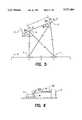
- FIG. 6is a diagram showing an example of the relationship between the moving body and the station seen from the side, according to the first embodiment of the present invention.
- FIG. 7is a diagram showing another example of the relationship between the moving body and the station seen from the side, according to the first embodiment of the present invention.
- FIG. 8is a diagram showing the relationship between the moving body and the station seen from the side, according to a second embodiment of the present invention.
- FIG. 9is a diagram showing a structure of a first light receiving device according to the first embodiment of the present invention.
- FIG. 10is a diagram showing a structure for rotating first and second light receiving devices according to the first embodiment of the present invention.
- FIG. 11is a diagram showing a structure of the first light receiving device according to a third embodiment of the present invention.
- FIG. 12is a diagram showing a structure for rotating first and second light receiving devices according to the third embodiment of the present invention.
- FIG. 13is a diagram showing the relationship between the moving body and the station seen from the side, when they are used in a house or building where a fluorescent lamp is used for lighting, according to a fourth embodiment of the present invention.
- FIG. 14is a diagram showing an example of a quantity of light emitted from the fluorescent lamp and each of the light emitting portions along a time axis, according to the fourth embodiment of the present invention.
- FIG. 15is a diagram showing another example of a quantity of light emitted from the fluorescent lamp and each of the light emitting portions along a time axis, according to the fourth embodiment of the present invention.
- FIG. 16is a diagram showing still another example of a quantity of light emitted from the fluorescent lamp and each of the light emitting portions along a time axis, according to the fourth embodiment of the present invention.
- FIG. 17is a diagram showing characteristics of light receiving data when two light emitting pulses are simultaneously received by a light receiving sensor having a wide directivity, according to the fourth embodiment of the present invention.
- FIG. 18is a diagram showing characteristics of light receiving data when two light emitting pulses are simultaneously received by a light receiving sensor having a narrow directivity, according to the fourth embodiment of the present invention.
- FIG. 19is a diagram showing a quantity of light emitted from the fluorescent lamp and each of the light emitting portions when the light receiving sensor having a wide directivity shown in FIG. 17 is used.
- FIG. 20is a circuit diagram showing a structure of an optical trigger circuit according to a fifth embodiment of the present invention.
- FIG. 21is a waveform diagram of current or voltage at each node in the circuit diagram of FIG. 20.
- FIG. 22is a circuit diagram showing a structure of the optical trigger circuit and the light emitting portion according to the fifth embodiment of the present invention.
- FIG. 23is a diagram showing a pulse signal at each node in the circuit diagram of FIG. 22.
- FIG. 24is a diagram showing an example of the positional relationship between the moving body and the station when the position detecting system according to each embodiment of the present invention is incorporated.
- FIG. 25is a diagram showing another example of the positional relationship between the moving body and the station when the position detecting system according to each embodiment of the present invention is incorporated.
- FIG. 26is a diagram showing an example of control operation of the moving body according to a sixth embodiment of the present invention.
- FIG. 27is a diagram showing another example of control operation of the moving body according to the sixth embodiment of the present invention.
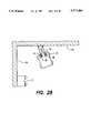
- FIG. 28is a diagram showing an example of control operation of the moving body according to a seventh embodiment of the present invention.
- FIG. 29shows the relationship between the quantity of light and time according to another method of removing the quantity of light of a fluorescent lamp, according to the fourth embodiment of the present invention.
- FIG. 1is a block diagram showing a structure of a light emitting unit according to the first embodiment of the present invention.
- a light emitting unit 1includes a control portion 3 configured with a CPU at its center, and a synchronizing signal generating portion 5, a first light emitting portion 7 including a light emitting diode, and a second light emitting portion 9 including a light emitting diode, all connected to control portion 3.
- First light emitting portion 7 and second light emitting portion 9are controlled by control portion 3 to emit light in synchronism with a signal generated by synchronizing signal generating portion 5.
- the directivity of light emitting portion 9 (7)is wide in order to emit light in as wide a range as possible. Therefore, in this embodiment, a light emitting portion having a directivity of 180° is used.
- FIG. 2is a block diagram showing a structure of a light receiving unit attached to a moving body according to the first embodiment of the present invention.
- a light receiving unit 10is structured with a control unit 23 including a CPU as its center.
- a control portion 23including a CPU as its center.
- a light receiving portion 13including a photodiode
- a rotating portion 15rotating light receiving portion 13 for changing the light receiving direction of light receiving portion 13, which configure a first light receiving device 11.
- a light receiving portion 19including a photodiode
- a rotating portion 21rotating light receiving portion 19, which configure a second light receiving device 17 spaced by a prescribed distance in a plane from first light receiving device 11.
- a synchronizing signal generating portion 31 for generating a synchronizing signal synchronizing light receiving timings of light receiving portions 13 and 19, and a calculating portion 25 for performing a prescribed calculation based on quantities of light reception obtained from light receiving portions 13 and 19are also connected to control portion 23. Further, a drive control portion 27 controlling a driving portion 29 of the moving body based on the result of calculating portion 25 is connected to calculating portion 25.
- light receiving portion 19 (13) having a directivity of ⁇ 10°is used. However, a light receiving portion having a narrower directivity may be used, thereby increasing the detection precision.
- FIG. 3is a plan view showing a state where the light emitting unit and the light receiving unit shown in FIGS. 1 and 2 are incorporated in a station serving as a reference station and a moving body, according to the first embodiment of the present invention.
- light receiving portion 13 and light receiving portion 19are provided on the upper surface of a moving body 33 which is a first object or a second object including driving wheels 35 separately from each other by a prescribed distance, and rotate with the direction penetrating the sheet of paper in the figure as a rotating axis.
- first light emitting portion 7 and second light emitting portion 9are spaced from each other in a plane on the side surface of a station 37 serving as a reference station which is the first object.
- Light receiving portion 13 and light receiving portion 19rotate in order to receive light emitted from first light emitting portion 7 and second light emitting portion 9. With the rotation, the quantity of light reception changes according to the directivity of the light receiving portion. When the peak of the directivity of the light receiving portion matches the direction of the light emitting portion, the quantity of light reception is maximized.
- FIG. 4is a diagram showing the relationship of azimuths of the light receiving portions with respect to the light emitting portions in the relation between moving body 33 and station 37 shown in FIG. 3.
- FIG. 5is a diagram showing the mutual positional relationship between respective light receiving portions and respective light emitting portions by extraction from FIG. 4.
- light emitting portion 7 and light emitting portion 9are attached at the positions of length L and length -L around the origin 0 of station 37.
- light receiving portion 13 and light receiving portion 19 in moving body 33are spaced from each other by a prescribed distance R in a plane.
- the straight-line distances of light receiving portion 13 from light emitting portion 7 and light emitting portion 9are Lr2 and Lr1, respectively, and the azimuths are ⁇ r2 and ⁇ r1, respectively.
- the straight-line distances of light receiving portion 19 from light emitting portion 7 and light emitting portion 9are Lf2 and Lf1, respectively, and the azimuths are ⁇ f2 and ⁇ f1.
- the absolute coordinates of light receiving portion 13 and light receiving portion 19 around the origin 0are (Xr, Yr) and (Xf, Yf). More specifically, (Xf, Yf) and (Xr, Yr) are the absolute coordinates around the starting position (origin 0) of station 37, based on which the relative position and the relative direction between the moving body and the station are detected.
- each of the light receiving portionsis detected based on the rotation angle of the light receiving portion when the quantity of light reception takes the maximum value. Based on the detected azimuth, the straight-line distances of light receiving portions 13 and 19 from light emitting portions 7 and 9 and the absolute coordinates thereof around the origin 0 are found according to the following expressions: ##EQU1##
- FIG. 6is a diagram showing the relationship between moving body 33 and station 37 in FIG. 3 seen from the side.
- light receiving portion 13 (19) provided on moving body 33receives light emitted from first light emitting portion 7 (second light emitting portion 9) provided on the side face of station 37. Therefore, positioning the light receiving portion and the light emitting portion at an approximately equal horizontal level increases the quantity of light reception and improves the detection precision of the azimuth.
- a convex cylindrical lens 8a (8b)in front of the light emitting portion, and by collecting light emitted from light emitting portion 7 (9) in the vertical direction at the height position of the light receiving portion, the quantity of light reception can be increased, and the decision precision of the azimuth can be improved.
- FIG. 8shows at (1) the relationship between the moving body and the station according to the second embodiment of the present invention, and shows at (2) a perspective view of the moving body.
- first light emitting portion 7(second light emitting portion 9) provided on station 37 is positioned higher than light receiving portion 13 (19) at the horizontal level.
- first light emitting portion 7(second light emitting portion 9) provided on station 37 is positioned higher than light receiving portion 13 (19) at the horizontal level.
- a concave cylindrical lens 43is provided in front of first light receiving portion 13 (second light receiving portion 19), so that the directivity of the light receiving portion is extended in the vertical direction.
- the light emitting portion and the light receiving portioncan be positioned under a decreased restriction upon height. As a result, a degree of freedom in designing a position detecting system is increased, enabling efficient designing.
- the caseis shown where the light emitting portion is positioned higher than the light receiving portion. However, it is needless to say that the similar effects can be expected in the case where the light receiving portion is positioned higher than the light emitting portion.
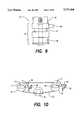
- FIG. 9is a side view showing a structure of first light receiving device 11 shown in FIG. 3.
- FIG. 10is a diagram showing a structure of a rotation driving device of first light receiving device 11 and second light receiving device 17 of FIG. 3.
- first light receiving device 11includes a torque limiter 47 provided on a pulley 49, and a contacting member 45 provided thereon. Pulley 49, torque limiter 47, and contacting member 45 form a rotating portion 15. Light receiving portion 13 is fixedly mounted on contacting member 45. Note that second light receiving device 17 is structured similar to first light receiving device 11.
- Timing belt 53is driven by a motor 51.
- rotating portion 15 and a rotating portion 21rotate clockwise through timing belt 53 as shown in FIG. 10.
- Stoppers 48 and 50are provided at the positions opposing contacting members 45 and 46.
- torque limiter 47operates and driving from the pulleys to rotate contacting members 45 and 46, that is, light receiving portions 13 and 19 is disconnected. Accordingly, the origin can be precisely positioned at the time of rotation of light receiving portions 13 and 19.
- stoppers 48 and 50have a position adjustment function for fine adjustment of a stopper position, not shown.
- motor 51may be provided for each of light receiving portions 13 and 19.
- FIGS. 11 and 12show the third embodiment of the present invention, corresponding to the first embodiment shown in FIGS. 9 and 10, respectively.
- a contacting member 55is provided directly on a pulley 57. Contacting member 55 and pulley 57 form rotating portion 15. Light receiving portion 13 is fixedly mounted on rotating portion 15. Second light receiving device 17 is structured similar to first light receiving device 11.
- Pulley 57 of first light receiving device 11 and the pulley of second light receiving device 17are bridged by a timing belt 54.
- Timing belt 54is placed with its smooth face in contact with the pulleys and its face with projections towards outside.
- Motor 51engages the face with projections of timing belt 54.
- each of first light receiving device 11 and second light receiving device 17rotates clockwise as shown in the figure.
- Stoppers 48 and 50are provided opposing contacting members 55 and 56, respectively.
- the smooth face of timing belt 54operates similar to the torque limiter in the previous embodiment. More specifically, there is a slip between pulley 57 and timing belt 54, causing timing belt 54 to run idly. Accordingly, the origin can be precisely positioned at the time of rotation of light receiving portions 13 and 19.
- a driving motor and a timing beltmay be provided for each light receiving device.
- FIG. 13is a side view showing the positional relationship between the moving body and the station under the circumstances where a fluorescent lamp is on, according to the fourth embodiment of the present invention.
- moving body 33when a traveling vehicle or robot is used in a house or building where fluorescent lamps 59 and 61 are used for lighting, light receiving portion 13 (19) of moving body 33 receives not only light emitted from first light emitting portion 7 (second light emitting portion 9), but also light emitted from fluorescent lamps 59 and 61. As a result, there is a possibility that the detection precision of azimuth is reduced by change in the quantity of light of light receiving portion 13 (19). Therefore, in this embodiment, moving body 33 and station 37 are respectively provided with fluorescent lamp light receiving portions 63 and 65 for receiving only light emitted from the fluorescent lamps on their upper surfaces.
- First light emitting portion 7(second light emitting portion 9) emits light in synchronism with a frequency 1/2 of a light emitting frequency of the fluorescent lamp detected by light reception of fluorescent lamp light receiving portion 65.
- light receiving portion 13 (19)is controlled to receive light in synchronism with a frequency of the fluorescent lamp detected by light reception of fluorescent lamp light receiving portion 63. Accordingly, by finding the difference between two continuous quantities of light reception provided corresponding to the frequency of the fluorescent lamp, the quantity of light received from the fluorescent lamp can be eliminated.
- the positional relationshipcan be detected similar to the case where light receiving portion 13 (19) receives only light emitted from first light emitting portion 7 (second light emitting portion 9).
- the positional relationship between moving body 33 and station 37can be precisely detected.
- FIG. 14is a diagram showing the relationship between the quantities of light emitted from a fluorescent lamp and a light emitting portion over time according to the fourth embodiment shown in FIG. 13.
- the light emitting portionemits light in a light emitting cycle, i.e. period, which is two times that of the fluorescent lamp.
- a light receiving data reception timelight is received in a light receiving cycle as long which is the same as the light emitting cycle of the fluorescent lamp.
- the light emitting cycleis an integer multiple of the light receiving cycle.
- the light receiving portion of the moving bodycontinues to detect a quantity of light while shifting the phase of the light receiving cycle, and starts synchronization with the light emitting portion at the point where the difference between the quantities of light reception at adjacent data reception times is the largest.
- the light emitting portioncan be synchronized with the light receiving portion.
- the light receiving portionagain continues detection of a quantity of light while shifting the phase of the light receiving cycle a prescribed time after the start of sampling, and again starts synchronization with the light emitting portion at the point where the quantity of light takes the maximum value. Accordingly, it is possible to carry out precise light emission and light reception.
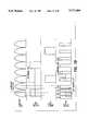
- FIG. 29shows the relationship between the quantity of light and time according to another method of removing the quantity of light of a fluorescent lamp, according to the fourth embodiment of the present invention.
- the light emitting cycle of the light emitting unitis basically set to an even multiple of the fluorescent light cycle
- the light receiving cycle of the light receiving unitis basically set to one half the light emitting cycle.
- the fluorescent light cycleis an integer multiple of the light receiving cycle.
- the light emitting cycleis set to two times the fluorescent light cycle.
- the circuit shown in FIG. 20is set equal to the fluorescent light cycle.
- the light emitting cycleis four times the fluorescent light cycle
- the light receiving cycleis one half the light emitting cycle (two times the fluorescent light cycle).
- Shown at (3) of FIG. 29is a modification of the example shown at (1) of FIG. 29.
- the light emitting cycleis twice the length of the fluorescent light cycle, and the time during which light is emitted by the light emitting unit is shorter than one fluorescent light cycle. Also in this case, by setting the light receiving cycle one half the light emitting cycle, the quantity of fluorescent light can be removed.
- the operations cycle of the light emitting unitis twice that of the fluorescent lamp, and the operating cycle of the light receiving unit is one-half that of the fluorescent lamp.
- the duty cycle of light emissionis set so that light is emitted for 1/2 cycle and light is not emitted for 1/2 cycle.
- are calculated based on the values of the quantities of light reception D1, D2, D3, and D4 at four continuous data reception times. With a larger output as valid data, the quantity of light emitted from the fluorescent lamp is canceled, whereby the quantity of light emitted from only the light emitting unit can be measured.
- the light receiving unitcan always receive precisely either one of the above two absolute value data obtained in the light emitting cycle of one light emitting pulse. Consequently, the same effect can be brought about as the case where the light receiving unit is synchronized with the light emitting unit.
- the light emitting unitemits light during a cycle which is twice that of the fluorescent lamp in this embodiment.
- the light emitting unitmay emit light not only over a cycle which is twice that of the fluorescent lamp, but also over a cycle which is n times (wherein n is an integer) that of the fluorescent lamp.
- the duty cycle of light emissionis set so that light is emitted for 1/n cycle, and light is not emitted for (n-1)/n cycle.
- the light receiving unitcalculates
- the light receiving portionagain receives light at a frequency two times that of the fluorescent light, and it is again synchronized with the light emitting portion with a timing, at which accurate data is received, as a valid light receiving timing, whereby transmission and reception of data can be carried out precisely.
- the above-described method of removing the quantity of light of the fluorescent lampcan be applied to a system other than the position detecting system of this embodiment.
- this methodcan be applied to a system detecting the relative position between a first object having only one light emitting unit and a second object having only one light receiving unit by the light receiving unit receiving light from the light emitting unit, a system, such as a distance measuring system of a camera, for measuring the distance to an object to be photographed by reflecting light emitted from a light emitting unit by the object to be photographed, and receiving the reflected light by a light receiving unit, and the like.
- a systemsuch as a distance measuring system of a camera, for measuring the distance to an object to be photographed by reflecting light emitted from a light emitting unit by the object to be photographed, and receiving the reflected light by a light receiving unit, and the like.
- FIG. 17shows light receiving data in the case where a sensor having a wide directivity is used as a light receiving sensor on the moving body.
- FIG. 18shows light receiving data in the case where a sensor having a narrow directivity is used as a light receiving sensor.
- the peak of a light receiving signalcannot be determined, resulting in the case where angular data cannot be calculated. Therefore, when a light receiving sensor having a wide directivity is used, two light emitting portions do not emit light simultaneously. Rather, as shown in FIG. 19, two light emitting portions emit light alternately at a frequency 1/4 that of the fluorescent light. As a result, the same effect can be brought about as the case where a light receiving sensor having a narrow directivity is used, and the position detection is implemented using an inexpensive light receiving sensor.
- FIG. 20is a circuit diagram of an optical trigger circuit according to the fifth embodiment of the present invention.
- FIG. 21is a waveform diagram at each node in the circuit of FIG. 20.
- the light receiving unitin addition to light receiving portions for detecting light reception, includes an optical trigger circuit mainly receiving light of the fluorescent lamp and providing a synchronizing signal. More specifically, the light receiving portion receives light in synchronism with a trigger signal provided from the optical trigger circuit, so that the light receiving portion can be completely synchronized with light emission of the fluorescent lamp.
- the optical trigger circuitincludes a photodiode 67 for receiving light of the fluorescent lamp, an amplifying portion 69 for amplifying a voltage generated by light of the fluorescent lamp entering photodiode 67 with a feedback resistor, a high-pass filter 71 for differentiating the amplified voltage, a comparing portion 73 including a comparator comparing a voltage provided from high-pass filter 71 and a prescribed voltage, and an output portion 75 providing a signal output from comparing portion 73 as an optical trigger signal.
- FIG. 21shows a waveform diagram of a voltage value V1 at a node N1 of FIG. 20 at (1), a waveform diagram of a voltage value V2 at a node N2 together with the threshold value at (2), and a pulse signal V3 as an optical trigger signal provided from an output terminal SO of output portion 75 at (3).
- the light receiving portioncan be completely synchronized with light emission of the fluorescent lamp.
- FIG. 22is a circuit diagram of an optical trigger circuit provided in the light emitting unit of the station, according to the fifth embodiment of the present invention.
- FIG. 23is a waveform diagram of an output signal at nodes N 3 , N 4 , and N 5 of FIG. 22.
- amplifying portion 69, high-pass filter 71, and comparing portion 73are structured similar to those of the trigger circuit on the light receiving device side shown in FIG. 20.
- This optical trigger circuitfurther includes a light emitting signal output portion 77 including a flip-flop 78 provided on the output side of comparing portion 73, and a monostable multivibrator 78' receiving an output from flip-flop 78, and a light emitting portion 79 including a light emitting diode 81 receiving an output from light emitting signal output portion 77.
- a pulse signal in synchronism with the light emitting cycle of the fluorescent lampis provided at node N 3 .
- flip-flop 78counts an input signal and inverts output for every input of one pulse. More specifically, a pulse signal as shown at (2) of FIG.
- both the light emitting portion and the light receiving portioncan emit and receive light completely in synchronism with the light emitting cycle of the fluorescent lamp, resulting in very high precision of calculation of azimuth based on light reception.
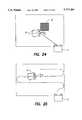
- FIG. 24is a plan view showing the relationship between the moving body in which the position detecting system is incorporated and the station according to the above each embodiment of the present invention.
- two light receiving portions having a rotation function of the light receiving unit provided on moving body 33repeatedly rotate to sample signals from two light emitting portions provided on station 37 serving as a reference station.
- the light receiving portionscalculate the absolute position and the direction (deviation angle, that is, position angle ⁇ ) of moving body 33 with respect to station 37 when the light receiving signal takes the maximum value, and provide the calculation results to a drive control portion.
- moving body 33can return to station 37 with safety.
- the light emitting unit and the light receiving unitmay be positioned oppositely. However, the light emitting unit consumes more power than the light receiving unit generally. It is preferable to place the light emitting unit on the side of a larger power supplying ability of a power source.
- FIG. 25is a plan view showing a state where the moving body travels by dead reckoning in the relationship between the moving body in which the position detecting system is incorporated and the station according to the above each embodiment of the present invention.
- dead reckoningthat is, the case where moving body 33 estimates and recognizes its own position based on data from an internal sensor (data from an encoder or gyrosensor provided to right and left driving wheels, for example), and travels on the floor.
- the position detecting systemwould detect the relative position and the direction of moving body 33 with respect to station 37 serving as a reference station, and calculate the angle and distance to be corrected to the reference traveling route based on the detection results.
- the position detecting systemprovides the calculation results to a driving portion, whereby the system can guide moving body 33 to the reference traveling route while correcting the relative position of moving body 33.
- FIG. 26is a diagram showing an example where light emitting portions and light receiving portions are provided on the moving body itself according to the sixth embodiment of the present invention.
- the position detecting systemhas a function of measuring the distance to an obstacle such as a wall, in addition to the above function.
- moving body 33approaches a wall 84.
- beam light irradiating units 85 and 87On the upper surface of moving body 33, provided are beam light irradiating units 85 and 87, and rotatable light receiving portions 13 and 19.
- beam light 86 directed to wall 84 from beam light irradiating unit 85is diffused and reflected by wall 84, and received by light receiving portion 13.
- Light receiving portion 13carries out sampling while rotating, and detects a deviation angle of light receiving portion 13 with respect to a wall face 80 when the light receiving signal takes the maximum value. Based on the detected deviation angle, the distance between moving body 33 and wall 84 is calculated according to the principle of trigonometric distance measurement, and the calculation result is provided to a driving portion 35, whereby the traveling of moving body 33 can be controlled.
- the moving bodyBy using light receiving portions for detecting the position and the direction of the moving body with respect to the station as described above, it is possible to calculate the distance to wall 84.
- the moving bodycan stop to avoid collision, or travel along the wall with a constant distance kept from the wall as shown in FIG. 27, while measuring the distance to the wall.
- FIG. 28shows a diagram according to the seventh embodiment of the present invention.
- Beam light irradiating units 88 and 89are provided on the upper surfaces of rotatable light receiving portions 13 and 19.
- beam light emitted from beam light irradiating units 88 and 89 towards wall 84is diffused and reflected by wall 84, and received by light receiving portions 13 and 19.
- Light receiving portions 13 and 19carry out sampling while rotating, and detect deviation angles of light receiving portions 13 and 19 with respect to wall face 80 when the light receiving signals take the maximum value. Based on the detected deviation angles, light receiving portions 13 and 19 calculate the distance and the angle between moving body 33 and wall 84, and provide the calculation results to driving portion 35. Accordingly, the light receiving portions can control the traveling of moving body 33.
- lightis used for transmission and reception between the light emitting unit and the light receiving unit in the above each embodiment.
- transmission and receptioncan be carried out using a supersonic wave or electromagnetic wave.
Landscapes
- Engineering & Computer Science (AREA)
- Physics & Mathematics (AREA)
- Radar, Positioning & Navigation (AREA)
- Remote Sensing (AREA)
- General Physics & Mathematics (AREA)
- Electromagnetism (AREA)
- Aviation & Aerospace Engineering (AREA)
- Automation & Control Theory (AREA)
- Length Measuring Devices By Optical Means (AREA)
Abstract
Description
Claims (27)
Applications Claiming Priority (4)
| Application Number | Priority Date | Filing Date | Title |
|---|---|---|---|
| JP5057594 | 1994-03-22 | ||
| JP6-050575 | 1994-03-22 | ||
| JP7-015750 | 1995-02-02 | ||
| JP7015750AJPH07311041A (en) | 1994-03-22 | 1995-02-02 | Position detector |
Publications (1)
| Publication Number | Publication Date |
|---|---|
| US5717484Atrue US5717484A (en) | 1998-02-10 |
Family
ID=26351954
Family Applications (1)
| Application Number | Title | Priority Date | Filing Date |
|---|---|---|---|
| US08/405,781Expired - LifetimeUS5717484A (en) | 1994-03-22 | 1995-03-17 | Position detecting system |
Country Status (2)
| Country | Link |
|---|---|
| US (1) | US5717484A (en) |
| JP (1) | JPH07311041A (en) |
Cited By (33)
| Publication number | Priority date | Publication date | Assignee | Title |
|---|---|---|---|---|
| US6142252A (en)* | 1996-07-11 | 2000-11-07 | Minolta Co., Ltd. | Autonomous vehicle that runs while recognizing work area configuration, and method of selecting route |
| US6574536B1 (en)* | 1996-01-29 | 2003-06-03 | Minolta Co., Ltd. | Moving apparatus for efficiently moving on floor with obstacle |
| US20060050285A1 (en)* | 2004-09-06 | 2006-03-09 | Weller Keith S | Position Encoder with Directional Output |
| US20060190133A1 (en)* | 2005-02-18 | 2006-08-24 | Irobot Corporation | Autonomous surface cleaning robot for wet cleaning |
| US20070016328A1 (en)* | 2005-02-18 | 2007-01-18 | Andrew Ziegler | Autonomous surface cleaning robot for wet and dry cleaning |
| US20070114975A1 (en)* | 2004-01-21 | 2007-05-24 | Irobot Corporation | Autonomous robot auto-docking and energy management systems and methods |
| US20070179670A1 (en)* | 2002-01-24 | 2007-08-02 | Irobot Corporation | Navigational control system for a robotic device |
| US20070213892A1 (en)* | 2001-06-12 | 2007-09-13 | Irobot Corporation | Method and System for Multi-Mode Coverage For An Autonomous Robot |
| US20070250212A1 (en)* | 2005-12-02 | 2007-10-25 | Halloran Michael J | Robot system |
| US20080065265A1 (en)* | 2006-05-31 | 2008-03-13 | Irobot Corporation | Detecting robot stasis |
| US20080091305A1 (en)* | 2005-12-02 | 2008-04-17 | Irobot Corporation | Coverage robot mobility |
| US20080276408A1 (en)* | 2007-05-09 | 2008-11-13 | Irobot Corporation | Autonomous coverage robot |
| US20090319083A1 (en)* | 2001-01-24 | 2009-12-24 | Irobot Corporation | Robot Confinement |
| US20100032853A1 (en)* | 2008-08-11 | 2010-02-11 | Nitto Denko Corporation | Method for manufacturing optical waveguide |
| US20100049365A1 (en)* | 2001-06-12 | 2010-02-25 | Irobot Corporation | Method and System for Multi-Mode Coverage For An Autonomous Robot |
| US20100049364A1 (en)* | 2002-09-13 | 2010-02-25 | Irobot Corporation | Navigational Control System for a Robotic Device |
| US7706917B1 (en) | 2004-07-07 | 2010-04-27 | Irobot Corporation | Celestial navigation system for an autonomous robot |
| US20100115716A1 (en)* | 2004-01-28 | 2010-05-13 | Irobot Corporation | Debris Sensor for Cleaning Apparatus |
| US20100257690A1 (en)* | 2002-01-03 | 2010-10-14 | Irobot Corporation | Autonomous floor-cleaning robot |
| US20100271617A1 (en)* | 2007-08-01 | 2010-10-28 | Koninklijke Philips Electronics N.V. | Vehicle positioning measurement system and method |
| US20100275405A1 (en)* | 2005-02-18 | 2010-11-04 | Christopher John Morse | Autonomous surface cleaning robot for dry cleaning |
| US20110125323A1 (en)* | 2009-11-06 | 2011-05-26 | Evolution Robotics, Inc. | Localization by learning of wave-signal distributions |
| US8380350B2 (en) | 2005-12-02 | 2013-02-19 | Irobot Corporation | Autonomous coverage robot navigation system |
| US8412377B2 (en) | 2000-01-24 | 2013-04-02 | Irobot Corporation | Obstacle following sensor scheme for a mobile robot |
| US8418303B2 (en) | 2006-05-19 | 2013-04-16 | Irobot Corporation | Cleaning robot roller processing |
| US8428778B2 (en) | 2002-09-13 | 2013-04-23 | Irobot Corporation | Navigational control system for a robotic device |
| US8584305B2 (en) | 2005-12-02 | 2013-11-19 | Irobot Corporation | Modular robot |
| US8788092B2 (en) | 2000-01-24 | 2014-07-22 | Irobot Corporation | Obstacle following sensor scheme for a mobile robot |
| US8800107B2 (en) | 2010-02-16 | 2014-08-12 | Irobot Corporation | Vacuum brush |
| US8972052B2 (en) | 2004-07-07 | 2015-03-03 | Irobot Corporation | Celestial navigation system for an autonomous vehicle |
| US9008835B2 (en) | 2004-06-24 | 2015-04-14 | Irobot Corporation | Remote control scheduler and method for autonomous robotic device |
| US9320398B2 (en) | 2005-12-02 | 2016-04-26 | Irobot Corporation | Autonomous coverage robots |
| EP2236069B1 (en)* | 2009-04-01 | 2019-12-25 | Vorwerk & Co. Interholding GmbH | Self-propelled device, in particular self-propelled dust collection device |
Families Citing this family (4)
| Publication number | Priority date | Publication date | Assignee | Title |
|---|---|---|---|---|
| JPH11349280A (en)* | 1998-06-05 | 1999-12-21 | Shinko Electric Co Ltd | Suspended conveying device |
| KR100854653B1 (en)* | 2006-05-12 | 2008-08-27 | 주식회사 한울로보틱스 | Location recognition device of mobile robot using charging station |
| CN103251354A (en)* | 2012-02-16 | 2013-08-21 | 恩斯迈电子(深圳)有限公司 | Control method of sweeping robot |
| JP6636289B2 (en)* | 2015-09-29 | 2020-01-29 | 東芝ライフスタイル株式会社 | Traveling device |
Citations (5)
| Publication number | Priority date | Publication date | Assignee | Title |
|---|---|---|---|---|
| US2830487A (en)* | 1955-05-31 | 1958-04-15 | Louis E Griffith | Automatic range finding device |
| US4328545A (en)* | 1978-08-01 | 1982-05-04 | Imperial Chemical Industries Limited | Driverless vehicle autoguide by light signals and two directional detectors |
| US4688933A (en)* | 1985-05-10 | 1987-08-25 | The Laitram Corporation | Electro-optical position determining system |
| US4910464A (en)* | 1985-11-06 | 1990-03-20 | Formula Systems Limited | Proximity detector |
| US5039217A (en)* | 1989-03-27 | 1991-08-13 | Mitsubishi Denki Kabushiki Kaisha | Optical transceiver apparatus for detecting distance between two cars |
- 1995
- 1995-02-02JPJP7015750Apatent/JPH07311041A/ennot_activeWithdrawn
- 1995-03-17USUS08/405,781patent/US5717484A/ennot_activeExpired - Lifetime
Patent Citations (5)
| Publication number | Priority date | Publication date | Assignee | Title |
|---|---|---|---|---|
| US2830487A (en)* | 1955-05-31 | 1958-04-15 | Louis E Griffith | Automatic range finding device |
| US4328545A (en)* | 1978-08-01 | 1982-05-04 | Imperial Chemical Industries Limited | Driverless vehicle autoguide by light signals and two directional detectors |
| US4688933A (en)* | 1985-05-10 | 1987-08-25 | The Laitram Corporation | Electro-optical position determining system |
| US4910464A (en)* | 1985-11-06 | 1990-03-20 | Formula Systems Limited | Proximity detector |
| US5039217A (en)* | 1989-03-27 | 1991-08-13 | Mitsubishi Denki Kabushiki Kaisha | Optical transceiver apparatus for detecting distance between two cars |
Cited By (134)
| Publication number | Priority date | Publication date | Assignee | Title |
|---|---|---|---|---|
| US6574536B1 (en)* | 1996-01-29 | 2003-06-03 | Minolta Co., Ltd. | Moving apparatus for efficiently moving on floor with obstacle |
| US6142252A (en)* | 1996-07-11 | 2000-11-07 | Minolta Co., Ltd. | Autonomous vehicle that runs while recognizing work area configuration, and method of selecting route |
| US9446521B2 (en) | 2000-01-24 | 2016-09-20 | Irobot Corporation | Obstacle following sensor scheme for a mobile robot |
| US8478442B2 (en) | 2000-01-24 | 2013-07-02 | Irobot Corporation | Obstacle following sensor scheme for a mobile robot |
| US8761935B2 (en) | 2000-01-24 | 2014-06-24 | Irobot Corporation | Obstacle following sensor scheme for a mobile robot |
| US8412377B2 (en) | 2000-01-24 | 2013-04-02 | Irobot Corporation | Obstacle following sensor scheme for a mobile robot |
| US8565920B2 (en) | 2000-01-24 | 2013-10-22 | Irobot Corporation | Obstacle following sensor scheme for a mobile robot |
| US8788092B2 (en) | 2000-01-24 | 2014-07-22 | Irobot Corporation | Obstacle following sensor scheme for a mobile robot |
| US9144361B2 (en) | 2000-04-04 | 2015-09-29 | Irobot Corporation | Debris sensor for cleaning apparatus |
| US9582005B2 (en) | 2001-01-24 | 2017-02-28 | Irobot Corporation | Robot confinement |
| US8659255B2 (en) | 2001-01-24 | 2014-02-25 | Irobot Corporation | Robot confinement |
| US8659256B2 (en) | 2001-01-24 | 2014-02-25 | Irobot Corporation | Robot confinement |
| US9622635B2 (en) | 2001-01-24 | 2017-04-18 | Irobot Corporation | Autonomous floor-cleaning robot |
| US20100312429A1 (en)* | 2001-01-24 | 2010-12-09 | Irobot Corporation | Robot confinement |
| US8686679B2 (en) | 2001-01-24 | 2014-04-01 | Irobot Corporation | Robot confinement |
| US20100268384A1 (en)* | 2001-01-24 | 2010-10-21 | Irobot Corporation | Robot confinement |
| US8368339B2 (en) | 2001-01-24 | 2013-02-05 | Irobot Corporation | Robot confinement |
| US20090319083A1 (en)* | 2001-01-24 | 2009-12-24 | Irobot Corporation | Robot Confinement |
| US9167946B2 (en) | 2001-01-24 | 2015-10-27 | Irobot Corporation | Autonomous floor cleaning robot |
| US9038233B2 (en) | 2001-01-24 | 2015-05-26 | Irobot Corporation | Autonomous floor-cleaning robot |
| US20100049365A1 (en)* | 2001-06-12 | 2010-02-25 | Irobot Corporation | Method and System for Multi-Mode Coverage For An Autonomous Robot |
| US8396592B2 (en) | 2001-06-12 | 2013-03-12 | Irobot Corporation | Method and system for multi-mode coverage for an autonomous robot |
| US9104204B2 (en) | 2001-06-12 | 2015-08-11 | Irobot Corporation | Method and system for multi-mode coverage for an autonomous robot |
| US8838274B2 (en) | 2001-06-12 | 2014-09-16 | Irobot Corporation | Method and system for multi-mode coverage for an autonomous robot |
| US20070213892A1 (en)* | 2001-06-12 | 2007-09-13 | Irobot Corporation | Method and System for Multi-Mode Coverage For An Autonomous Robot |
| US8463438B2 (en) | 2001-06-12 | 2013-06-11 | Irobot Corporation | Method and system for multi-mode coverage for an autonomous robot |
| US20100263142A1 (en)* | 2001-06-12 | 2010-10-21 | Irobot Corporation | Method and system for multi-mode coverage for an autonomous robot |
| US8671507B2 (en) | 2002-01-03 | 2014-03-18 | Irobot Corporation | Autonomous floor-cleaning robot |
| US8516651B2 (en) | 2002-01-03 | 2013-08-27 | Irobot Corporation | Autonomous floor-cleaning robot |
| US20100257691A1 (en)* | 2002-01-03 | 2010-10-14 | Irobot Corporation | Autonomous floor-cleaning robot |
| US20100257690A1 (en)* | 2002-01-03 | 2010-10-14 | Irobot Corporation | Autonomous floor-cleaning robot |
| US8474090B2 (en) | 2002-01-03 | 2013-07-02 | Irobot Corporation | Autonomous floor-cleaning robot |
| US8656550B2 (en) | 2002-01-03 | 2014-02-25 | Irobot Corporation | Autonomous floor-cleaning robot |
| US20110131741A1 (en)* | 2002-01-03 | 2011-06-09 | Jones Joseph L | Autonomous Floor-Cleaning Robot |
| US8763199B2 (en) | 2002-01-03 | 2014-07-01 | Irobot Corporation | Autonomous floor-cleaning robot |
| US20100263158A1 (en)* | 2002-01-03 | 2010-10-21 | Irobot Corporation | Autonomous floor-cleaning robot |
| US20070179670A1 (en)* | 2002-01-24 | 2007-08-02 | Irobot Corporation | Navigational control system for a robotic device |
| US9128486B2 (en) | 2002-01-24 | 2015-09-08 | Irobot Corporation | Navigational control system for a robotic device |
| US20100049364A1 (en)* | 2002-09-13 | 2010-02-25 | Irobot Corporation | Navigational Control System for a Robotic Device |
| US8515578B2 (en) | 2002-09-13 | 2013-08-20 | Irobot Corporation | Navigational control system for a robotic device |
| US8793020B2 (en) | 2002-09-13 | 2014-07-29 | Irobot Corporation | Navigational control system for a robotic device |
| US9949608B2 (en) | 2002-09-13 | 2018-04-24 | Irobot Corporation | Navigational control system for a robotic device |
| US8386081B2 (en) | 2002-09-13 | 2013-02-26 | Irobot Corporation | Navigational control system for a robotic device |
| US8428778B2 (en) | 2002-09-13 | 2013-04-23 | Irobot Corporation | Navigational control system for a robotic device |
| US9215957B2 (en) | 2004-01-21 | 2015-12-22 | Irobot Corporation | Autonomous robot auto-docking and energy management systems and methods |
| US20070267998A1 (en)* | 2004-01-21 | 2007-11-22 | Irobot Corporation | Autonomous Robot Auto-Docking and Energy Management Systems and Methods |
| US20070114975A1 (en)* | 2004-01-21 | 2007-05-24 | Irobot Corporation | Autonomous robot auto-docking and energy management systems and methods |
| US8854001B2 (en) | 2004-01-21 | 2014-10-07 | Irobot Corporation | Autonomous robot auto-docking and energy management systems and methods |
| US8749196B2 (en) | 2004-01-21 | 2014-06-10 | Irobot Corporation | Autonomous robot auto-docking and energy management systems and methods |
| US8390251B2 (en) | 2004-01-21 | 2013-03-05 | Irobot Corporation | Autonomous robot auto-docking and energy management systems and methods |
| US20080007203A1 (en)* | 2004-01-21 | 2008-01-10 | Irobot Corporation | Autonomous robot auto-docking and energy management systems and methods |
| US8461803B2 (en) | 2004-01-21 | 2013-06-11 | Irobot Corporation | Autonomous robot auto-docking and energy management systems and methods |
| US8456125B2 (en) | 2004-01-28 | 2013-06-04 | Irobot Corporation | Debris sensor for cleaning apparatus |
| US8253368B2 (en) | 2004-01-28 | 2012-08-28 | Irobot Corporation | Debris sensor for cleaning apparatus |
| US20100115716A1 (en)* | 2004-01-28 | 2010-05-13 | Irobot Corporation | Debris Sensor for Cleaning Apparatus |
| US8378613B2 (en) | 2004-01-28 | 2013-02-19 | Irobot Corporation | Debris sensor for cleaning apparatus |
| US9008835B2 (en) | 2004-06-24 | 2015-04-14 | Irobot Corporation | Remote control scheduler and method for autonomous robotic device |
| US9486924B2 (en) | 2004-06-24 | 2016-11-08 | Irobot Corporation | Remote control scheduler and method for autonomous robotic device |
| US8874264B1 (en) | 2004-07-07 | 2014-10-28 | Irobot Corporation | Celestial navigation system for an autonomous robot |
| US8634958B1 (en)* | 2004-07-07 | 2014-01-21 | Irobot Corporation | Celestial navigation system for an autonomous robot |
| US7706917B1 (en) | 2004-07-07 | 2010-04-27 | Irobot Corporation | Celestial navigation system for an autonomous robot |
| US8972052B2 (en) | 2004-07-07 | 2015-03-03 | Irobot Corporation | Celestial navigation system for an autonomous vehicle |
| US9229454B1 (en) | 2004-07-07 | 2016-01-05 | Irobot Corporation | Autonomous mobile robot system |
| US8594840B1 (en) | 2004-07-07 | 2013-11-26 | Irobot Corporation | Celestial navigation system for an autonomous robot |
| US9223749B2 (en) | 2004-07-07 | 2015-12-29 | Irobot Corporation | Celestial navigation system for an autonomous vehicle |
| US8634956B1 (en) | 2004-07-07 | 2014-01-21 | Irobot Corporation | Celestial navigation system for an autonomous robot |
| US20060050285A1 (en)* | 2004-09-06 | 2006-03-09 | Weller Keith S | Position Encoder with Directional Output |
| US20100275405A1 (en)* | 2005-02-18 | 2010-11-04 | Christopher John Morse | Autonomous surface cleaning robot for dry cleaning |
| US20080127445A1 (en)* | 2005-02-18 | 2008-06-05 | Irobot Corporation | Autonomous surface cleaning robot for wet cleaning |
| US8382906B2 (en) | 2005-02-18 | 2013-02-26 | Irobot Corporation | Autonomous surface cleaning robot for wet cleaning |
| US8387193B2 (en) | 2005-02-18 | 2013-03-05 | Irobot Corporation | Autonomous surface cleaning robot for wet and dry cleaning |
| US8985127B2 (en) | 2005-02-18 | 2015-03-24 | Irobot Corporation | Autonomous surface cleaning robot for wet cleaning |
| US8966707B2 (en) | 2005-02-18 | 2015-03-03 | Irobot Corporation | Autonomous surface cleaning robot for dry cleaning |
| US8670866B2 (en) | 2005-02-18 | 2014-03-11 | Irobot Corporation | Autonomous surface cleaning robot for wet and dry cleaning |
| US9445702B2 (en) | 2005-02-18 | 2016-09-20 | Irobot Corporation | Autonomous surface cleaning robot for wet and dry cleaning |
| US20080155768A1 (en)* | 2005-02-18 | 2008-07-03 | Irobot Corporation | Autonomous surface cleaning robot for wet and dry cleaning |
| US8855813B2 (en) | 2005-02-18 | 2014-10-07 | Irobot Corporation | Autonomous surface cleaning robot for wet and dry cleaning |
| US8739355B2 (en) | 2005-02-18 | 2014-06-03 | Irobot Corporation | Autonomous surface cleaning robot for dry cleaning |
| US10470629B2 (en) | 2005-02-18 | 2019-11-12 | Irobot Corporation | Autonomous surface cleaning robot for dry cleaning |
| US20070016328A1 (en)* | 2005-02-18 | 2007-01-18 | Andrew Ziegler | Autonomous surface cleaning robot for wet and dry cleaning |
| US20060190133A1 (en)* | 2005-02-18 | 2006-08-24 | Irobot Corporation | Autonomous surface cleaning robot for wet cleaning |
| US8392021B2 (en) | 2005-02-18 | 2013-03-05 | Irobot Corporation | Autonomous surface cleaning robot for wet cleaning |
| US8774966B2 (en) | 2005-02-18 | 2014-07-08 | Irobot Corporation | Autonomous surface cleaning robot for wet and dry cleaning |
| US8782848B2 (en) | 2005-02-18 | 2014-07-22 | Irobot Corporation | Autonomous surface cleaning robot for dry cleaning |
| US8600553B2 (en) | 2005-12-02 | 2013-12-03 | Irobot Corporation | Coverage robot mobility |
| US20110077802A1 (en)* | 2005-12-02 | 2011-03-31 | Halloran Michael J | Robot System |
| US10524629B2 (en) | 2005-12-02 | 2020-01-07 | Irobot Corporation | Modular Robot |
| US20070250212A1 (en)* | 2005-12-02 | 2007-10-25 | Halloran Michael J | Robot system |
| US20080091305A1 (en)* | 2005-12-02 | 2008-04-17 | Irobot Corporation | Coverage robot mobility |
| US8661605B2 (en) | 2005-12-02 | 2014-03-04 | Irobot Corporation | Coverage robot mobility |
| US8606401B2 (en) | 2005-12-02 | 2013-12-10 | Irobot Corporation | Autonomous coverage robot navigation system |
| US8584307B2 (en) | 2005-12-02 | 2013-11-19 | Irobot Corporation | Modular robot |
| US9599990B2 (en) | 2005-12-02 | 2017-03-21 | Irobot Corporation | Robot system |
| US8954192B2 (en) | 2005-12-02 | 2015-02-10 | Irobot Corporation | Navigating autonomous coverage robots |
| US8950038B2 (en) | 2005-12-02 | 2015-02-10 | Irobot Corporation | Modular robot |
| US8584305B2 (en) | 2005-12-02 | 2013-11-19 | Irobot Corporation | Modular robot |
| US9392920B2 (en) | 2005-12-02 | 2016-07-19 | Irobot Corporation | Robot system |
| US8978196B2 (en) | 2005-12-02 | 2015-03-17 | Irobot Corporation | Coverage robot mobility |
| US9320398B2 (en) | 2005-12-02 | 2016-04-26 | Irobot Corporation | Autonomous coverage robots |
| US8761931B2 (en) | 2005-12-02 | 2014-06-24 | Irobot Corporation | Robot system |
| US9149170B2 (en) | 2005-12-02 | 2015-10-06 | Irobot Corporation | Navigating autonomous coverage robots |
| US9144360B2 (en) | 2005-12-02 | 2015-09-29 | Irobot Corporation | Autonomous coverage robot navigation system |
| US8380350B2 (en) | 2005-12-02 | 2013-02-19 | Irobot Corporation | Autonomous coverage robot navigation system |
| US8374721B2 (en) | 2005-12-02 | 2013-02-12 | Irobot Corporation | Robot system |
| US9492048B2 (en) | 2006-05-19 | 2016-11-15 | Irobot Corporation | Removing debris from cleaning robots |
| US9955841B2 (en) | 2006-05-19 | 2018-05-01 | Irobot Corporation | Removing debris from cleaning robots |
| US10244915B2 (en) | 2006-05-19 | 2019-04-02 | Irobot Corporation | Coverage robots and associated cleaning bins |
| US8418303B2 (en) | 2006-05-19 | 2013-04-16 | Irobot Corporation | Cleaning robot roller processing |
| US8572799B2 (en) | 2006-05-19 | 2013-11-05 | Irobot Corporation | Removing debris from cleaning robots |
| US8528157B2 (en) | 2006-05-19 | 2013-09-10 | Irobot Corporation | Coverage robots and associated cleaning bins |
| US8417383B2 (en) | 2006-05-31 | 2013-04-09 | Irobot Corporation | Detecting robot stasis |
| US20080065265A1 (en)* | 2006-05-31 | 2008-03-13 | Irobot Corporation | Detecting robot stasis |
| US9317038B2 (en) | 2006-05-31 | 2016-04-19 | Irobot Corporation | Detecting robot stasis |
| US8839477B2 (en) | 2007-05-09 | 2014-09-23 | Irobot Corporation | Compact autonomous coverage robot |
| US10299652B2 (en) | 2007-05-09 | 2019-05-28 | Irobot Corporation | Autonomous coverage robot |
| US10070764B2 (en) | 2007-05-09 | 2018-09-11 | Irobot Corporation | Compact autonomous coverage robot |
| US9480381B2 (en) | 2007-05-09 | 2016-11-01 | Irobot Corporation | Compact autonomous coverage robot |
| US20080281470A1 (en)* | 2007-05-09 | 2008-11-13 | Irobot Corporation | Autonomous coverage robot sensing |
| US20080276408A1 (en)* | 2007-05-09 | 2008-11-13 | Irobot Corporation | Autonomous coverage robot |
| US8726454B2 (en) | 2007-05-09 | 2014-05-20 | Irobot Corporation | Autonomous coverage robot |
| US8239992B2 (en) | 2007-05-09 | 2012-08-14 | Irobot Corporation | Compact autonomous coverage robot |
| US11498438B2 (en) | 2007-05-09 | 2022-11-15 | Irobot Corporation | Autonomous coverage robot |
| US8438695B2 (en) | 2007-05-09 | 2013-05-14 | Irobot Corporation | Autonomous coverage robot sensing |
| US20100271617A1 (en)* | 2007-08-01 | 2010-10-28 | Koninklijke Philips Electronics N.V. | Vehicle positioning measurement system and method |
| US8174683B2 (en)* | 2007-08-01 | 2012-05-08 | Koninklijke Philips Electronics N.V. | Vehicle positioning measurement system and method |
| US20100032853A1 (en)* | 2008-08-11 | 2010-02-11 | Nitto Denko Corporation | Method for manufacturing optical waveguide |
| EP2236069B1 (en)* | 2009-04-01 | 2019-12-25 | Vorwerk & Co. Interholding GmbH | Self-propelled device, in particular self-propelled dust collection device |
| US8930023B2 (en) | 2009-11-06 | 2015-01-06 | Irobot Corporation | Localization by learning of wave-signal distributions |
| US9623557B2 (en) | 2009-11-06 | 2017-04-18 | Irobot Corporation | Localization by learning of wave-signal distributions |
| US9440354B2 (en) | 2009-11-06 | 2016-09-13 | Irobot Corporation | Localization by learning of wave-signal distributions |
| US20110125323A1 (en)* | 2009-11-06 | 2011-05-26 | Evolution Robotics, Inc. | Localization by learning of wave-signal distributions |
| US10314449B2 (en) | 2010-02-16 | 2019-06-11 | Irobot Corporation | Vacuum brush |
| US8800107B2 (en) | 2010-02-16 | 2014-08-12 | Irobot Corporation | Vacuum brush |
| US11058271B2 (en) | 2010-02-16 | 2021-07-13 | Irobot Corporation | Vacuum brush |
Also Published As
| Publication number | Publication date |
|---|---|
| JPH07311041A (en) | 1995-11-28 |
Similar Documents
| Publication | Publication Date | Title |
|---|---|---|
| US5717484A (en) | Position detecting system | |
| US4729660A (en) | Position measuring apparatus of moving vehicle | |
| KR930004881B1 (en) | Inter-vehicle distance detection device | |
| RU2419104C2 (en) | Method and system to locate moving transport facilities | |
| EP0346538A1 (en) | Control method for an unmanned vehicle | |
| EP1421409A1 (en) | Six dimensional laser tracking system and method | |
| JPS62263507A (en) | Guiding device for movable body | |
| KR102595870B1 (en) | Compact Lidar Sensor | |
| JPH01316808A (en) | Self-propelled vehicle steering control device | |
| Beom et al. | Mobile robot localization using a single rotating sonar and two passive cylindrical beacons | |
| JPH0690042B2 (en) | Position control device for self-propelled vehicle | |
| WO2019064750A1 (en) | Distance measurement device and moving body | |
| KR20230153970A (en) | Compact Lidar Sensor | |
| US7233389B2 (en) | System and method for the measurement of the velocity and acceleration of objects | |
| KR20180023608A (en) | Driving system of automated guided vehicle | |
| JP2007101492A (en) | Mobile robot distance and position detection device | |
| JP2005063184A (en) | Self-propelled mobile device and position correction method | |
| WO2020045445A1 (en) | Distance measuring device, distance measuring device group, and distance measuring device system | |
| JP2717826B2 (en) | Steering control device for self-propelled vehicles | |
| US20180017678A1 (en) | Power efficient lidar | |
| Seki et al. | Positioning system for indoor mobile robot using active ultrasonic beacons | |
| JP2739262B2 (en) | Moving object position measurement device | |
| CN114594769B (en) | Walking navigation system, computer room inspection system and computer room inspection method | |
| JPS6316267A (en) | Measurement system for moving body | |
| JPH0716164Y2 (en) | Vehicle position / speed detector |
Legal Events
| Date | Code | Title | Description |
|---|---|---|---|
| AS | Assignment | Owner name:MINOLTA CO., LTD., JAPAN Free format text:ASSIGNMENT OF ASSIGNORS INTEREST;ASSIGNORS:HAMAGUCHI, TAKAYUKI;KAWAGOE, NOBUKAZU;KAWAKAMI, YUICHI;AND OTHERS;REEL/FRAME:007392/0545 Effective date:19950313 | |
| FEPP | Fee payment procedure | Free format text:PAYOR NUMBER ASSIGNED (ORIGINAL EVENT CODE: ASPN); ENTITY STATUS OF PATENT OWNER: LARGE ENTITY | |
| STCF | Information on status: patent grant | Free format text:PATENTED CASE | |
| FPAY | Fee payment | Year of fee payment:4 | |
| FPAY | Fee payment | Year of fee payment:8 | |
| FPAY | Fee payment | Year of fee payment:12 | |
| AS | Assignment | Owner name:KONICA MINOLTA HOLDINGS, INC., JAPAN Free format text:MERGER;ASSIGNOR:MINOLTA CO., LTD.;REEL/FRAME:031815/0890 Effective date:20031010 Owner name:KONICA MINOLTA, INC., JAPAN Free format text:CHANGE OF NAME;ASSIGNOR:KONICA MINOLTA HOLDINGS, INC.;REEL/FRAME:031815/0828 Effective date:20130401 | |
| AS | Assignment | Owner name:MONEUAL, INC., KOREA, REPUBLIC OF Free format text:ASSIGNMENT OF ASSIGNORS INTEREST;ASSIGNOR:KONICA MINOLTA, INC.;REEL/FRAME:033580/0231 Effective date:20140820 |