US5717465A - Apparatus for coding an object region of a video signal by using a rearranged block-based coding technique - Google Patents
Apparatus for coding an object region of a video signal by using a rearranged block-based coding techniqueDownload PDFInfo
- Publication number
- US5717465A US5717465AUS08/674,944US67494496AUS5717465AUS 5717465 AUS5717465 AUS 5717465AUS 67494496 AUS67494496 AUS 67494496AUS 5717465 AUS5717465 AUS 5717465A
- Authority
- US
- United States
- Prior art keywords
- subblock
- row
- column
- shifted
- processing block
- Prior art date
- Legal status (The legal status is an assumption and is not a legal conclusion. Google has not performed a legal analysis and makes no representation as to the accuracy of the status listed.)
- Expired - Lifetime
Links
- 238000000034methodMethods0.000titledescription22
- 230000008707rearrangementEffects0.000claimsabstractdescription12
- 230000000694effectsEffects0.000claimsdescription77
- 238000003491arrayMethods0.000claimsdescription50
- 238000004364calculation methodMethods0.000claimsdescription7
- 230000003044adaptive effectEffects0.000claimsdescription3
- 238000010586diagramMethods0.000description4
- 230000005540biological transmissionEffects0.000description3
- 230000004044responseEffects0.000description3
- 238000003786synthesis reactionMethods0.000description3
- 238000013139quantizationMethods0.000description2
- 238000004891communicationMethods0.000description1
- 238000013144data compressionMethods0.000description1
- 239000011159matrix materialSubstances0.000description1
- 238000012986modificationMethods0.000description1
- 230000004048modificationEffects0.000description1
Images


Classifications
- H—ELECTRICITY
- H04—ELECTRIC COMMUNICATION TECHNIQUE
- H04N—PICTORIAL COMMUNICATION, e.g. TELEVISION
- H04N19/00—Methods or arrangements for coding, decoding, compressing or decompressing digital video signals
- H04N19/10—Methods or arrangements for coding, decoding, compressing or decompressing digital video signals using adaptive coding
- H04N19/169—Methods or arrangements for coding, decoding, compressing or decompressing digital video signals using adaptive coding characterised by the coding unit, i.e. the structural portion or semantic portion of the video signal being the object or the subject of the adaptive coding
- H04N19/17—Methods or arrangements for coding, decoding, compressing or decompressing digital video signals using adaptive coding characterised by the coding unit, i.e. the structural portion or semantic portion of the video signal being the object or the subject of the adaptive coding the unit being an image region, e.g. an object
- H—ELECTRICITY
- H04—ELECTRIC COMMUNICATION TECHNIQUE
- H04N—PICTORIAL COMMUNICATION, e.g. TELEVISION
- H04N19/00—Methods or arrangements for coding, decoding, compressing or decompressing digital video signals
- H04N19/10—Methods or arrangements for coding, decoding, compressing or decompressing digital video signals using adaptive coding
- H04N19/169—Methods or arrangements for coding, decoding, compressing or decompressing digital video signals using adaptive coding characterised by the coding unit, i.e. the structural portion or semantic portion of the video signal being the object or the subject of the adaptive coding
- H—ELECTRICITY
- H04—ELECTRIC COMMUNICATION TECHNIQUE
- H04N—PICTORIAL COMMUNICATION, e.g. TELEVISION
- H04N19/00—Methods or arrangements for coding, decoding, compressing or decompressing digital video signals
- H04N19/10—Methods or arrangements for coding, decoding, compressing or decompressing digital video signals using adaptive coding
- H04N19/102—Methods or arrangements for coding, decoding, compressing or decompressing digital video signals using adaptive coding characterised by the element, parameter or selection affected or controlled by the adaptive coding
- H04N19/119—Adaptive subdivision aspects, e.g. subdivision of a picture into rectangular or non-rectangular coding blocks
- H—ELECTRICITY
- H04—ELECTRIC COMMUNICATION TECHNIQUE
- H04N—PICTORIAL COMMUNICATION, e.g. TELEVISION
- H04N19/00—Methods or arrangements for coding, decoding, compressing or decompressing digital video signals
- H04N19/10—Methods or arrangements for coding, decoding, compressing or decompressing digital video signals using adaptive coding
- H04N19/134—Methods or arrangements for coding, decoding, compressing or decompressing digital video signals using adaptive coding characterised by the element, parameter or criterion affecting or controlling the adaptive coding
- H04N19/136—Incoming video signal characteristics or properties
- H04N19/14—Coding unit complexity, e.g. amount of activity or edge presence estimation
- H—ELECTRICITY
- H04—ELECTRIC COMMUNICATION TECHNIQUE
- H04N—PICTORIAL COMMUNICATION, e.g. TELEVISION
- H04N19/00—Methods or arrangements for coding, decoding, compressing or decompressing digital video signals
- H04N19/10—Methods or arrangements for coding, decoding, compressing or decompressing digital video signals using adaptive coding
- H04N19/169—Methods or arrangements for coding, decoding, compressing or decompressing digital video signals using adaptive coding characterised by the coding unit, i.e. the structural portion or semantic portion of the video signal being the object or the subject of the adaptive coding
- H04N19/17—Methods or arrangements for coding, decoding, compressing or decompressing digital video signals using adaptive coding characterised by the coding unit, i.e. the structural portion or semantic portion of the video signal being the object or the subject of the adaptive coding the unit being an image region, e.g. an object
- H04N19/176—Methods or arrangements for coding, decoding, compressing or decompressing digital video signals using adaptive coding characterised by the coding unit, i.e. the structural portion or semantic portion of the video signal being the object or the subject of the adaptive coding the unit being an image region, e.g. an object the region being a block, e.g. a macroblock
- H—ELECTRICITY
- H04—ELECTRIC COMMUNICATION TECHNIQUE
- H04N—PICTORIAL COMMUNICATION, e.g. TELEVISION
- H04N19/00—Methods or arrangements for coding, decoding, compressing or decompressing digital video signals
- H04N19/20—Methods or arrangements for coding, decoding, compressing or decompressing digital video signals using video object coding
Definitions
- the present inventionrelates to an apparatus for encoding an object region of a video signal; and, more particularly, to an apparatus for effectively encoding an object region of a video signal by using a rearranged block-based coding technique.
- a large amount of digital datais needed to define each video frame signal since a video line signal in the video frame signal comprises a sequence of digital data referred to as pixel values. Since, however, the available frequency bandwidth of a conventional transmission channel is limited, in order to transmit the large amount of digital data therethrough, it is inevitable to compress or reduce the volume of data through the use of a data compression technique, especially in the case of a low bit-rate video signal encoder, e.g., video-telephone or teleconference system.
- One of such techniques for encoding video signals for a low bit-rate encoding systemis the so-called object-oriented analysis-synthesis coding technique(see Michael Hotter, "Object-Oriented Analysis-Synthesis Coding Based on Moving Two-Dimensional Objects", Signal Processing: Image Communication, 2, No. 4, pp. 409-428(December, 1990)).
- an input video imageis first divided into two parts: i.e., one or more object regions; and a background region. Then, the background region and the object region are separately coded by using various block-based coding techniques, e.g., DCT (discrete cosine transform) and quantization, on a block-by-block basis.
- various block-based coding techniquese.g., DCT (discrete cosine transform) and quantization
- DCTdiscrete cosine transform
- quantizatione.g., discrete cosine transform
- the object regionmay be of an arbitrary shape
- a processing block encompassing the object regionis used for encoding the object region by using the block-based DCT coding technique, wherein the processing block is first divided into a number of equal-sized subblocks. The equal-sized subblocks are then sequentially coded by using the DCT coding technique.
- the area lying outside the object region in a subblockis padded by using a certain value which is determined by using a known padding technique, e.g., an extended interpolation (EI) or a shape-adaptive (SA) DCT coding technique.
- a known padding techniquee.g., an extended interpolation (EI) or a shape-adaptive (SA) DCT coding technique.
- an object of the inventionto provide an apparatus for effectively coding an object region of a video signal by using a block-based video coding circuit, capable of providing a minimum number of subblocks encompassing the object region, to thereby improve the coding efficiency of the video signal.
- Another object of the present inventionis to provide an apparatus having a subblock rearrangement circuit which is capable of effectively providing the minimum number of subblocks encompassing the object region by using a mean activity for the rearranged subblocks.
- an apparatus for coding an arbitrarily shaped object region of a video signalwherein the video signal includes a zero-masked region, the object region, and shape information representing the shape of the object region, and is divided into a plurality of equal-sized subblocks, each subblock having M ⁇ M pixels with M being a positive integer, which comprises:
- processing block decision meansfor selecting a processing block encompassing the object region based on the shape information to generate a processing block signal and processing block position data, wherein the processing block includes P ⁇ Q subblocks, P and Q being positive integers;
- subblock rearrangement meansfor rearranging the subblocks of the processing block to generate a rearranged processing block having a minimum number of the subblocks encompassing the object region and position information representing positions of the rearranged subblocks;
- transform coding meansfor converting the rearranged processing block on a subblock-by-subblock basis into a transform coded video signal.
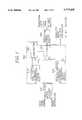
- FIG. 1is a schematic block diagram showing a video encoding apparatus employing a subblock rearrangement circuit in accordance with the present invention
- FIG. 2Adescribes an exemplary processing block encompassing an object region
- FIG. 2Bshows an exemplary row rearranged processing block
- FIG. 2Cdepicts an exemplary column rearranged processing block
- FIG. 3offers a detailed block diagram of the row-shifted subblock generation circuit shown in FIG. 1;
- FIG. 4demonstrates a detailed block diagram of the column-shifted subblock generation circuit shown in FIG. 1.
- the video encoding apparatusincludes a processing block decision circuit 200, a subblock rearrangement circuit 300, and a transform coding circuit 400.
- the processing block decision circuit 200decides a processing block by using the zero masked video frame signal and the shape information, wherein the processing block includes a multiplicity of equal sized subblocks encompassing the object region, e.g., P ⁇ Q subblocks, P and Q being positive integers.
- Each of the subblockshas M ⁇ M pixels, M being a positive integer, e.g., 8 ⁇ 8 pixels or 16 ⁇ 16 pixels.
- the multiplicity of the subblocksis arranged in a matrix form having P number of row subblock arrays and Q number of column subblock arrays. For instance, referring to FIG. 2A, there is shown an exemplary processing block 110 which has only 5 ⁇ 5 subblocks encompassing an object region 120 for the sake of simplicity.
- the processing block 110includes 5 row subblock arrays 10, 21, 31, 41 and 51, each having 5 subblocks, and 5 column subblock arrays 11, 12, 13, 14 and 15, each having 5 subblocks.
- a processing block signal representing the processing block and processing block position information denoting the position of the processing blockis generated and provided to the subblock rearrangement circuit 300, wherein the subblock rearrangement circuit 300 includes a row-shifted subblock generation circuit 310, a column-shifted subblock generation circuit 320, a comparator 330 and a selector 340.
- the subblocks of the processing blockare rearranged; and a rearranged processing block signal and rearranged subblock array position information are generated, wherein the rearranged processing block signal includes the minimum number of the subblocks encompassing the object region.
- the rearranged processing block signalincludes the minimum number of the subblocks encompassing the object region.
- each of the row subblock arraysis first shifted to obtain a row rearranged processing block entailing a minimum mean activity and then rearranged subblock array position information representing positions of the shifted row subblock arrays and a row mean activity signal denoting the mean activity of the row rearranged processing block are generated.
- each of the column subblock arraysis first shifted to obtain a column rearranged processing block entailing another minimum mean activity and then column subblock array position information representing positions of the shifted column subblock arrays and a column activity signal denoting the activity of the second rearranged processing block are generated. Details of the row-shifted and the column-shifted subblock generation circuits 310 and 320 will be described with reference to FIGS. 3 and 4.
- the row and the column rearranged processing blocks, and the row and the column subblock array position informationare provided to the selector 340, while the row and column mean activity signals are relayed to the comparator 330.
- the row mean activity signal and the column mean activity signalare compared and a rearranged processing block having a mean activity smaller than the other is selected to generate a selection signal representing the selected rearranged processing block.
- the selected rearranged processing blockis provided as the rearranged processing block to be transmitted to the transform coding circuit 400.
- the subblock array position information of the selected rearranged processing blockis also relayed via the selector 340 to a known next processor, e.g., a variable length coder (not shown).
- the transform coding circuit 400processes the rearranged processing block outputted from the selector 340 to provide a set of transform coefficients to the next processor.
- the transform coding circuit 400is implemented by using a known discrete cosine transform (DCT) coding circuit employing a known extended interpolation (EI) technique or a known shape adaptive (SA) DCT coding technique.
- DCTdiscrete cosine transform
- EIextended interpolation
- SAshape adaptive
- the transform coding circuitcan also include a known quantization circuit.
- the row-shifted subblock generation circuit 310includes M number of row shift circuits 311-1, 311-2, . . . , 311-M, M number of mean activity calculators 312-1, 312-2, . . . , 312-M, a comparator 313, a selector 314, a row activity calculation circuit 315, and a buffer 316.
- FIG. 3is intended to show M number of the row shift circuits, only 3 circuits are depicted for the sake of simplicity.
- the row shift circuits 311-1, 311-2, . . . , and 311-Mreceive a row subblock array simultaneously and each shifts the row subblock array by a predetermined pixel position, e.g., one pixel, to generate a shifted row subblock array. For instance, referring to FIG.
- the row subblock array 10is simultaneously relayed to the row shift circuits 311-1 to 311-M and a first row shift circuit 311-1 provides a first shifted subblock array 10-1 shifted by one pixel position in row direction.
- a second row shift circuit 311-2 and an Mth row shift circuit 311-Mprovide a second shifted subblock array 10-2 shifted by two pixel positions and an Mth shifted subblock array 10-M shifted by M pixel positions in row direction, respectively. If the subblock is, as described above, formed of 8 ⁇ 8 pixels, M is 8.
- the row shift circuits 311-1 to 311-Mprovides respective subblock array position information and a set of shifted subblock arrays to the selector 314 and to the corresponding mean activity calculator 312-1 to 312-M, respectively.
- Each of the mean activity calculator 312-1 to 312-Mprovides the comparator 313 with a mean activity for each of the shifted subblock arrays.
- the mean activity valuesare compared with each other to select one of the shifted subblock arrays with the minimum mean activity. For example, if the second shifted subblock array has the minimum mean activity value among the shifted subblock arrays, the second shifted subblock is selected and the comparator 313 generates a selection signal denoting the second shifted subblock array as the selected shifted subblock array. The selection signal is then relayed to the selector 314 which, in response to the selection signal, provides the selected shifted subblock array and the corresponding subblock array position information to the buffer 316. The comparator 313 also provides the row activity calculator 315 with the mean activity value of the selected shifted subblock array.
- the above processis repeated until all of the P row subblock arrays (e.g., 10, 21, 31, 41 and 51 of FIG. 2A) are processed.
- the row activity calculator 315accumulates the mean activity values for each selected shifted subblock array as an accumulated mean activity value and then divides the accumulated mean activity value by the total number of selected shifted subblock arrays to generate the row mean activity signal which is transmitted to the comparator 330 shown in FIG. 1.
- the buffer 316temporarily stores the selected shifted subblock arrays until all of the selected shifted subblock arrays are stored and sequentially generates the stored subblocks as the row rearranged processing block (e.g. 130 of FIG. 2B) which is relayed to the selector 340 shown in FIG. 1.
- the column-shifted subblock generation circuit 320includes M number of column shift circuits 411-1, 411-2, . . . , 411-M, M number of mean activity calculators 412-1, 412-2, . . . , 412-M, a comparator 413, a selector 414, a column activity calculation circuit 415, and a buffer 416.
- the column shift circuits 411-1 to 411-Mreceive a column subblock array simultaneously and each shifts the column subblock array by a predetermined pixel position, e.g., one pixel, to generate a shifted column subblock array. For instance, referring to FIG.
- the column subblock array 11is simultaneously relayed to the column shift circuits 411-1 to 411-M and a first column shift circuit 411-1 provides a first shifted subblock array 11-1 shifted by one pixel position in column direction.
- a second column shift circuit 411-2 and an Mth column shift circuit 411-Mprovide a second shifted subblock array 11-2 shifted by two pixel positions and an Mth shifted subblock array 11-M shifted by M pixel positions in column direction, respectively. If the subblock is, as described above, formed of 8 ⁇ 8 pixels, M is 8.
- the column shift circuits 411-1 to 411-Mprovides respective subblock array position information and a set of shifted subblock arrays to the selector 414 and to the corresponding mean activity calculator 412-1 to 412-M, respectively.
- Each of the mean activity calculator 412-1 to 412-Mprovides the comparator 413 with a mean activity for each of the shifted subblock arrays.
- the mean activity valuesare compared with each other to select one of the shifted subblock arrays with the minimum mean activity. For example, if the second shifted subblock array has the minimum mean activity value among all the shifted subblock arrays, the second shifted subblock is selected and the comparator 413 generates a selection signal denoting the second shifted subblock as the selected shifted subblock array. The selection signal is then relayed to the selector 414 which, in response to the selection signal, provides the selected shifted subblock array and the corresponding subblock array position information to the buffer 416. The comparator 413 also provides the column activity calculator 415 with the mean activity value of the selected shifted subblock array.
- the above processis repeated until all of the Q column subblock arrays (e.g.,11, 12, 13, 14 and 15 of FIG. 2A) are processed.
- the column activity calculator 415accumulates the mean activity values for each selected shifted subblock array as an accumulated mean activity value and then divides the accumulated mean activity value by the total number of selected shifted subblock arrays to generate the column mean activity signal which is transmitted to the comparator 330 shown in FIG. 1.
- the buffer 416temporarily stores the selected shifted subblock arrays until all of the selected shifted subblock arrays are stored and sequentially generates the stored subblocks as the column rearranged processing block (e.g., 140 of FIG. 2B) which is relayed to the selector 340 shown in FIG. 1.
- the number of subblocks encompassing the object region to be codedis effectively minimized so that data to be coded by the block-based coding technique, e.g., DCT coding technique can be greatly reduced to thereby improve the coding efficiency of the video encoder. Furthermore, the minimum number of subblocks encompassing the object region can be effectively achieved by using mean activity calculation technique.
Landscapes
- Engineering & Computer Science (AREA)
- Multimedia (AREA)
- Signal Processing (AREA)
- Compression Or Coding Systems Of Tv Signals (AREA)
- Compression Of Band Width Or Redundancy In Fax (AREA)
Abstract
Description
Claims (9)
Applications Claiming Priority (2)
| Application Number | Priority Date | Filing Date | Title |
|---|---|---|---|
| KR1019960017810AKR100235064B1 (en) | 1996-05-23 | 1996-05-23 | Apparatus for coding objects using block based coding technique |
| KR96-17810 | 1996-05-23 |
Publications (1)
| Publication Number | Publication Date |
|---|---|
| US5717465Atrue US5717465A (en) | 1998-02-10 |
Family
ID=19459718
Family Applications (1)
| Application Number | Title | Priority Date | Filing Date |
|---|---|---|---|
| US08/674,944Expired - LifetimeUS5717465A (en) | 1996-05-23 | 1996-07-03 | Apparatus for coding an object region of a video signal by using a rearranged block-based coding technique |
Country Status (7)
| Country | Link |
|---|---|
| US (1) | US5717465A (en) |
| EP (1) | EP0809404B1 (en) |
| JP (1) | JP3833744B2 (en) |
| KR (1) | KR100235064B1 (en) |
| CN (1) | CN1103531C (en) |
| DE (1) | DE69638109D1 (en) |
| IN (1) | IN189531B (en) |
Cited By (10)
| Publication number | Priority date | Publication date | Assignee | Title |
|---|---|---|---|---|
| US5892849A (en)* | 1995-07-10 | 1999-04-06 | Hyundai Electronics Industries Co., Ltd. | Compaction/motion estimation method using a grid moving method for minimizing image information of an object |
| WO2000021207A1 (en)* | 1998-10-05 | 2000-04-13 | Sarnoff Corporation | Parameterized quantization matrix adaptation for video encoding |
| US6072908A (en)* | 1996-09-25 | 2000-06-06 | Hyundai Electronics Ind Co., Ltd. | Grid moving method using selective pixel search method and apparatus using the grid moving method |
| US6249548B1 (en) | 1998-07-10 | 2001-06-19 | U.S. Phillips Corporation | Motion vector processing |
| US6256417B1 (en) | 1996-06-28 | 2001-07-03 | Matsushita Electric Industrial Co., Ltd. | Image coding apparatus, image decoding apparatus, image coding method, image decoding method, image coding program recording media, image decoding program recording media |
| US6516095B1 (en)* | 1996-05-17 | 2003-02-04 | Matsushita Electric Industrial Co., Ltd. | Decoding apparatus for shape signal |
| KR100382516B1 (en)* | 1999-01-15 | 2003-05-01 | 주식회사 팬택앤큐리텔 | Object-based image signal coding/decoding apparatus and method |
| US20050031129A1 (en)* | 2003-08-04 | 2005-02-10 | Devantier Allan O. | System for selecting speaker locations in an audio system |
| US20050031130A1 (en)* | 2003-08-04 | 2005-02-10 | Devantier Allan O. | System for selecting correction factors for an audio system |
| US20050031135A1 (en)* | 2003-08-04 | 2005-02-10 | Devantier Allan O. | Statistical analysis of potential audio system configurations |
Families Citing this family (5)
| Publication number | Priority date | Publication date | Assignee | Title |
|---|---|---|---|---|
| EP1109409A3 (en)* | 1999-12-17 | 2011-11-30 | Canon Kabushiki Kaisha | Digital signal coding with division into tiles |
| JP2002271790A (en)* | 2001-03-07 | 2002-09-20 | Nikon Corp | Image compression device, electronic camera, and image processing program |
| IL158970A0 (en)* | 2001-05-22 | 2004-05-12 | Soliton Holdings Corp | Method for digital quantization |
| JP4218446B2 (en) | 2003-07-03 | 2009-02-04 | 株式会社ニコン | Electronic camera |
| CN114157867B (en)* | 2021-11-15 | 2025-09-02 | 北京达佳互联信息技术有限公司 | Image processing method, device, electronic device and storage medium |
Citations (6)
| Publication number | Priority date | Publication date | Assignee | Title |
|---|---|---|---|---|
| US4796087A (en)* | 1986-05-29 | 1989-01-03 | Jacques Guichard | Process for coding by transformation for the transmission of picture signals |
| US4837724A (en)* | 1986-05-12 | 1989-06-06 | U.S. Philips Corporation | Discrete cosine transform arrangement |
| US4858005A (en)* | 1986-02-17 | 1989-08-15 | Independent Broadcasting Authority | System for encoding broadcast quality television signals to enable transmission as an embedded code |
| US5363146A (en)* | 1992-03-02 | 1994-11-08 | Sony United Kingdom Ltd. | Motion compensated image processing |
| US5519503A (en)* | 1992-04-13 | 1996-05-21 | Sony Corporation | Picture reproducing apparatus |
| US5563718A (en)* | 1993-11-30 | 1996-10-08 | Polaroid Corporation | Image coding by use of discrete cosine transforms |
Family Cites Families (3)
| Publication number | Priority date | Publication date | Assignee | Title |
|---|---|---|---|---|
| JPH067828A (en)* | 1992-06-29 | 1994-01-18 | Kawasaki Steel Corp | Method for turning over thick plate |
| EP1098527A1 (en)* | 1994-11-04 | 2001-05-09 | Matsushita Electric Industrial Co., Ltd. | Picture coding apparatus and decoding apparatus |
| MY121607A (en)* | 1995-07-10 | 2006-02-28 | Hyundai Curitel Inc | Grid moving method of object image and apparatus using the same and compaction/motion estimation method using the same and apparatus thereof |
- 1996
- 1996-05-23KRKR1019960017810Apatent/KR100235064B1/ennot_activeExpired - Fee Related
- 1996-06-28DEDE69638109Tpatent/DE69638109D1/ennot_activeExpired - Lifetime
- 1996-06-28EPEP19960304819patent/EP0809404B1/ennot_activeExpired - Lifetime
- 1996-07-03USUS08/674,944patent/US5717465A/ennot_activeExpired - Lifetime
- 1996-07-04JPJP19276596Apatent/JP3833744B2/ennot_activeExpired - Fee Related
- 1996-07-04ININ1225CA1996patent/IN189531B/enunknown
- 1996-07-05CNCN96106955Apatent/CN1103531C/ennot_activeExpired - Fee Related
Patent Citations (6)
| Publication number | Priority date | Publication date | Assignee | Title |
|---|---|---|---|---|
| US4858005A (en)* | 1986-02-17 | 1989-08-15 | Independent Broadcasting Authority | System for encoding broadcast quality television signals to enable transmission as an embedded code |
| US4837724A (en)* | 1986-05-12 | 1989-06-06 | U.S. Philips Corporation | Discrete cosine transform arrangement |
| US4796087A (en)* | 1986-05-29 | 1989-01-03 | Jacques Guichard | Process for coding by transformation for the transmission of picture signals |
| US5363146A (en)* | 1992-03-02 | 1994-11-08 | Sony United Kingdom Ltd. | Motion compensated image processing |
| US5519503A (en)* | 1992-04-13 | 1996-05-21 | Sony Corporation | Picture reproducing apparatus |
| US5563718A (en)* | 1993-11-30 | 1996-10-08 | Polaroid Corporation | Image coding by use of discrete cosine transforms |
Non-Patent Citations (2)
| Title |
|---|
| Hotter, "Object-Oriented Analysis-Synthesis Coding Based On Moving Two-Dimensional Objects", Signal Processing: Image Communication, 2, No. 4, pp. 409-428, Dec. 1990. |
| Hotter, Object Oriented Analysis Synthesis Coding Based On Moving Two Dimensional Objects , Signal Processing: Image Communication, 2, No. 4, pp. 409 428, Dec. 1990.* |
Cited By (17)
| Publication number | Priority date | Publication date | Assignee | Title |
|---|---|---|---|---|
| US5892849A (en)* | 1995-07-10 | 1999-04-06 | Hyundai Electronics Industries Co., Ltd. | Compaction/motion estimation method using a grid moving method for minimizing image information of an object |
| US5903670A (en)* | 1995-07-10 | 1999-05-11 | Hyundai Electronics Industries Co., Ltd. | Grid moving apparatus for minimizing image information of an object |
| US6115501A (en)* | 1995-07-10 | 2000-09-05 | Hyundai Electronics Industries Co., Ltd. | Grid moving method for minimizing image information of an object |
| US6597814B2 (en)* | 1996-05-17 | 2003-07-22 | Matsushita Electric Industrial Co., Ltd. | Image coding for transmitting information of shape, pixel value, and coding modes |
| US6516095B1 (en)* | 1996-05-17 | 2003-02-04 | Matsushita Electric Industrial Co., Ltd. | Decoding apparatus for shape signal |
| US6256417B1 (en) | 1996-06-28 | 2001-07-03 | Matsushita Electric Industrial Co., Ltd. | Image coding apparatus, image decoding apparatus, image coding method, image decoding method, image coding program recording media, image decoding program recording media |
| US6072908A (en)* | 1996-09-25 | 2000-06-06 | Hyundai Electronics Ind Co., Ltd. | Grid moving method using selective pixel search method and apparatus using the grid moving method |
| US6249548B1 (en) | 1998-07-10 | 2001-06-19 | U.S. Phillips Corporation | Motion vector processing |
| US6546049B1 (en) | 1998-10-05 | 2003-04-08 | Sarnoff Corporation | Parameterized quantization matrix adaptation for video encoding |
| WO2000021207A1 (en)* | 1998-10-05 | 2000-04-13 | Sarnoff Corporation | Parameterized quantization matrix adaptation for video encoding |
| KR100382516B1 (en)* | 1999-01-15 | 2003-05-01 | 주식회사 팬택앤큐리텔 | Object-based image signal coding/decoding apparatus and method |
| US20050031129A1 (en)* | 2003-08-04 | 2005-02-10 | Devantier Allan O. | System for selecting speaker locations in an audio system |
| US20050031130A1 (en)* | 2003-08-04 | 2005-02-10 | Devantier Allan O. | System for selecting correction factors for an audio system |
| US20050031135A1 (en)* | 2003-08-04 | 2005-02-10 | Devantier Allan O. | Statistical analysis of potential audio system configurations |
| US8705755B2 (en)* | 2003-08-04 | 2014-04-22 | Harman International Industries, Inc. | Statistical analysis of potential audio system configurations |
| US8755542B2 (en) | 2003-08-04 | 2014-06-17 | Harman International Industries, Incorporated | System for selecting correction factors for an audio system |
| US8761419B2 (en) | 2003-08-04 | 2014-06-24 | Harman International Industries, Incorporated | System for selecting speaker locations in an audio system |
Also Published As
| Publication number | Publication date |
|---|---|
| KR100235064B1 (en) | 1999-12-15 |
| DE69638109D1 (en) | 2010-02-25 |
| JP3833744B2 (en) | 2006-10-18 |
| CN1103531C (en) | 2003-03-19 |
| KR970078658A (en) | 1997-12-12 |
| EP0809404A2 (en) | 1997-11-26 |
| IN189531B (en) | 2003-03-22 |
| EP0809404B1 (en) | 2010-01-06 |
| CN1168603A (en) | 1997-12-24 |
| JPH09327019A (en) | 1997-12-16 |
| EP0809404A3 (en) | 2003-11-19 |
Similar Documents
| Publication | Publication Date | Title |
|---|---|---|
| US5825929A (en) | Transformation block optimization method | |
| US5717465A (en) | Apparatus for coding an object region of a video signal by using a rearranged block-based coding technique | |
| US6339616B1 (en) | Method and apparatus for compression and decompression of still and motion video data based on adaptive pixel-by-pixel processing and adaptive variable length coding | |
| US5126962A (en) | Discrete cosine transform processing system | |
| US4816914A (en) | Method and apparatus for efficiently encoding and decoding image sequences | |
| KR100246878B1 (en) | Inverse discrete cosine transform processor | |
| JP5507077B2 (en) | Apparatus and method for encoding and calculating a discrete cosine transform using a butterfly processor | |
| JP2000507412A (en) | Sprite encoding | |
| US5351086A (en) | Low-bit rate interframe video encoder with adaptive transformation block selection | |
| CA2091579A1 (en) | Coding and decoding device for time-varying image | |
| JPH09233477A (en) | Motion vector generating method | |
| JP3202433B2 (en) | Quantization device, inverse quantization device, image processing device, quantization method, inverse quantization method, and image processing method | |
| JP3766686B2 (en) | Coder for TV image subband compatible coding. | |
| KR100242635B1 (en) | Variable length coding and variable length decoding system | |
| JPH08274650A (en) | Method of generating data structure representing haffman code method of generating haffman code and its device | |
| US5760845A (en) | Method for determining motion vectors based on a block matching motion estimation technique | |
| US5534930A (en) | Method for constructing a quantization pattern codebook | |
| JPH06169452A (en) | Image compression method with weighted screen | |
| EP0923250A1 (en) | Method and apparatus for adaptively encoding a binary shape signal | |
| KR100203694B1 (en) | Method and apparatus for encoding an image signal having an object by using an extension-interpolation technique | |
| KR100203713B1 (en) | Method and apparatus for processing an image signal including an object using a tension-interpolation technique | |
| JP2696869B2 (en) | Image coding device | |
| KR0178203B1 (en) | Improved Pattern Vector Coding System | |
| KR0178204B1 (en) | Pattern vector coding system using subband transform and method thereof | |
| CN1221291A (en) | Method and apparatus for adaptively encoding binary shape signal |
Legal Events
| Date | Code | Title | Description |
|---|---|---|---|
| AS | Assignment | Owner name:DAEWOO ELECTRONICS, CO., LTD., KOREA, REPUBLIC OF Free format text:ASSIGNMENT OF ASSIGNORS INTEREST;ASSIGNOR:KIM, JIN-HUN;REEL/FRAME:008087/0469 Effective date:19960618 | |
| FEPP | Fee payment procedure | Free format text:PAYOR NUMBER ASSIGNED (ORIGINAL EVENT CODE: ASPN); ENTITY STATUS OF PATENT OWNER: LARGE ENTITY | |
| STCF | Information on status: patent grant | Free format text:PATENTED CASE | |
| FPAY | Fee payment | Year of fee payment:4 | |
| AS | Assignment | Owner name:DAEWOO ELECTRONICS CORPORATION, KOREA, REPUBLIC OF Free format text:ASSIGNMENT OF ASSIGNORS INTEREST;ASSIGNOR:DAEWOO ELECTRONICS CO., LTD.;REEL/FRAME:013645/0159 Effective date:20021231 | |
| FPAY | Fee payment | Year of fee payment:8 | |
| FPAY | Fee payment | Year of fee payment:12 | |
| AS | Assignment | Owner name:MAPLE VISION TECHNOLOGIES INC., CANADA Free format text:ASSIGNMENT OF ASSIGNORS INTEREST;ASSIGNOR:DAEWOO ELECTRONICS CORPORATION;REEL/FRAME:027437/0446 Effective date:20111215 | |
| AS | Assignment | Owner name:QUARTERHILL INC., CANADA Free format text:MERGER AND CHANGE OF NAME;ASSIGNORS:MAPLE VISION TECHNOLOGIES INC.;QUARTERHILL INC.;REEL/FRAME:042935/0282 Effective date:20170601 | |
| AS | Assignment | Owner name:WI-LAN INC., CANADA Free format text:ASSIGNMENT OF ASSIGNORS INTEREST;ASSIGNOR:QUARTERHILL INC.;REEL/FRAME:043182/0859 Effective date:20170601 |