US5716327A - Body wall retraction system for wide cavity retraction - Google Patents
Body wall retraction system for wide cavity retractionDownload PDFInfo
- Publication number
- US5716327A US5716327AUS08/671,828US67182896AUS5716327AUS 5716327 AUS5716327 AUS 5716327AUS 67182896 AUS67182896 AUS 67182896AUS 5716327 AUS5716327 AUS 5716327A
- Authority
- US
- United States
- Prior art keywords
- lifting
- rods
- rod
- distal
- lifting rod
- Prior art date
- Legal status (The legal status is an assumption and is not a legal conclusion. Google has not performed a legal analysis and makes no representation as to the accuracy of the status listed.)
- Expired - Lifetime
Links
Images


Classifications
- A—HUMAN NECESSITIES
- A61—MEDICAL OR VETERINARY SCIENCE; HYGIENE
- A61B—DIAGNOSIS; SURGERY; IDENTIFICATION
- A61B17/00—Surgical instruments, devices or methods
- A61B17/02—Surgical instruments, devices or methods for holding wounds open, e.g. retractors; Tractors
- A61B17/0281—Abdominal wall lifters
- A—HUMAN NECESSITIES
- A61—MEDICAL OR VETERINARY SCIENCE; HYGIENE
- A61B—DIAGNOSIS; SURGERY; IDENTIFICATION
- A61B17/00—Surgical instruments, devices or methods
- A61B17/02—Surgical instruments, devices or methods for holding wounds open, e.g. retractors; Tractors
- A61B17/0218—Surgical instruments, devices or methods for holding wounds open, e.g. retractors; Tractors for minimally invasive surgery
- A—HUMAN NECESSITIES
- A61—MEDICAL OR VETERINARY SCIENCE; HYGIENE
- A61B—DIAGNOSIS; SURGERY; IDENTIFICATION
- A61B90/00—Instruments, implements or accessories specially adapted for surgery or diagnosis and not covered by any of the groups A61B1/00 - A61B50/00, e.g. for luxation treatment or for protecting wound edges
- A61B90/50—Supports for surgical instruments, e.g. articulated arms
- A—HUMAN NECESSITIES
- A61—MEDICAL OR VETERINARY SCIENCE; HYGIENE
- A61B—DIAGNOSIS; SURGERY; IDENTIFICATION
- A61B17/00—Surgical instruments, devices or methods
- A61B17/32—Surgical cutting instruments
- A61B2017/320044—Blunt dissectors
- A61B2017/320048—Balloon dissectors
Definitions
- the present inventionrelates to the field of surgical retractors and particularly to lifting the abdominal wall and retracting the abdominal contents during laparoscopic surgery.
- Laparoscopydates back to the turn of the 20th Century. Early laparoscopic techniques were used primarily for diagnostic purposes to view the internal organs, without the necessity of conventional surgery. Since the 1930s, laparoscopy has been used for sterilization and, more recently, for suturing hernias. U.S. Pat. Nos. 4,919,152 and 4,944,443 are concerned with techniques for suturing hernias. Another recent innovation is the use of laparoscopic surgery for removing the gallbladder.
- a well-known method of raising the abdominal wallis to insufflate the abdominal cavity with a suitable insufflation gas, such as air, or carbon dioxide.
- a suitable insufflation gassuch as air, or carbon dioxide.
- a significant disadvantage of gas insufflationis that instruments must be passed into the abdominal cavity through gas-tight seals, which significantly reduce the surgeon's feel of the instruments.
- the Californiayerli Endoscopic Retractor Model 1described in SURGICALLAPAROSCOPY AND ENDOSCOPY, Vol. 1, No. 2, 1991, pages 98-100, has a rigid rod with a hinged blade at the distal end.
- the bladecan rotate through 360 degrees about an axis perpendicular to the long axis of the rod.
- the bladeis aligned with the long axis of the rod for insertion into the abdomen through a small puncture. Once inside the abdomen, the blade is swivelled through about 90 degrees to form a T-shaped structure.
- the proximal end of the rodcan be raised by hand or by a rope, pulley and weight arrangement. Raising the rod causes the blade to engage the abdominal wall and to lift it.
- French patent application no. 90-03980shows a wire structure that is threaded into the abdomen through a small puncture to engage and to lift the abdominal wall.
- the applicationalso shows a fan retractor that has a first angle-shaped member having a first leg that engages with the abdominal wall, a tubular second leg having a bore, and a third leg, remote from the first leg, that has a hook-shaped member on its end distal from the second leg.
- a second angle-shaped memberhas a first leg that engages with the abdominal wall, a second leg that pivots within the bore of the second leg of the first angle-shaped member, and a third leg, remote from the first leg, that serves as an operating lever for the second angle-shaped member.
- the first legs of the angle-shaped membersare dosed together to insert them into the abdominal cavity through an incision.
- the third leg of the second angle-shaped memberis then operated to spread the first leg of the second angle-shaped member apart from the first leg of the first angle-shaped member.
- the first legsare engaged with the peritoneum inside the abdominal cavity.
- a lifting forceis then applied to the hook-shaped member to lift the retractor and hence to lift the abdominal wall.
- U.S. patent application Ser. No. 07/706,781the application of which this application is a Continuation-in-Part, describes a number of different mechanical devices that are inserted through one or more punctures into the abdomen. All or part of the device is then lifted to lift the abdominal wall away from the underlying abdominal organs.
- One of the devices described in this applicationis a fan retractor that is inserted in a closed condition into the abdomen, spread apart once inside the abdomen, and brought into contact with the peritoneum inside the abdomen. The fan retractor is then raised by a lifting arm to lift the abdominal wall.
- Another of the devicesis an inflatable device which is introduced laparoscopically and, once in place, inflated to engage and lift an extensive area of the abdominal wall.
- An abdominal wall retractorhas a lifting body and retraction rods that are capable of extending individually from the lifting body into the abdominal cavity.
- the retraction rodsare advanced into the abdominal cavity where they are used to raise and support the abdominal wall, thus creating a work space for laparoscopic surgery.
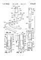
- FIG. 1is a perspective view of a first exemplary embodiment of the retraction system according to the invention showing the retraction rods in the closed position and further showing, in phantom lines, the retraction rods in the open position.
- FIG. 2is a top view of the first embodiment of FIG. 1 showing the retraction rods in the closed position and further showing, in phantom lines, the retraction rods in the open position.
- FIG. 3is a front view of the first embodiment of FIG. 1.
- FIG. 4is a side view of the first embodiment of FIG. 1.
- FIGS. 5 and 6are cross-sectional top views of the first embodiment of FIG. 1 taken along the planes designated 5--5 and 6--6, respectively, in FIG. 3.
- FIG. 7is a cross-sectional view of a retraction rod taken along the plane designated 7--7 in FIG. 2.
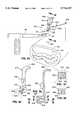
- FIGS. 8 through 10are a series of perspective views schematically showing use of the first embodiment of FIG. 1.
- FIG. 11is a perspective view of a second embodiment of the invention showing the retraction rods in the closed position and further showing, in phantom lines, the retraction rods in the open position.
- FIG. 12is a top view of the second embodiment of FIG. 11 showing the retraction rods in the closed position and further showing, in phantom lines, the retraction rods in the open position.
- FIG. 13is a front view of the second embodiment of FIG. 11.
- FIG. 14is a side view of the second embodiment of FIG. 11.
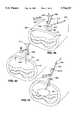
- FIG. 15is a perspective view of the third and preferred embodiment of a retraction system according to the invention.
- FIG. 16is an exploded cross-sectional view of a portion of the lifting body of the preferred retraction system of FIG. 15.
- FIG. 17is a cross-sectional side view of a portion of the lifting body of the preferred embodiment of FIG. 15 showing the positioning of its components prior to application of a lifting force.
- FIG. 18is a cross-sectional side view of a portion of the lifting body of the preferred embodiment of FIG. 15 showing the positioning of its components during loading.
- FIG. 19is a top view of the preferred retraction system of FIG. 15 with the splines and keys not shown.
- FIG. 20is a side view of the preferred retraction system of FIG. 15 with the splines and keys not shown.
- FIG. 21is a top view of the preferred retraction system of FIG. 15 utilizing paddles configured for upper abdominal retraction.
- FIG. 22is a perspective view of a fourth embodiment according to the present invention.
- FIG. 23is a perspective view of a fifth embodiment according to the present invention, showing the retraction rods in the closed position and further showing, in phantom lines, the retraction rods in the open position.
- FIG. 24is a top view of the fifth embodiment of FIG. 23 showing the retraction rods in the closed position and further showing, in phantom lines, the retraction rods in the open position.
- FIG. 25is a front view of the fifth embodiment of FIG. 23 showing the retraction rods in the closed position and further showing, in phantom lines, the retraction rods in the open position.
- FIG. 26is a side view of the fifth embodiment of FIG. 23 showing the retraction rods in the closed position and further showing, in phantom lines, the retraction rods in the open position.
- FIG. 27is a perspective view of a sixth embodiment according to the invention, showing the retraction rods in the closed position and further showing, in phantom lines, the retraction rods in the open position.
- FIG. 28is a top view of the sixth embodiment of FIG. 27 showing the retraction rods in the closed position and further showing, in phantom lines, the retraction rods in the open position.
- FIG. 29is a top view of the sixth embodiment of FIG. 27 showing the retraction rods in the closed position and further showing, in phantom lines, the retraction rods in the open position.
- FIGS. 30is a partial front view of a modified version of the sixth embodiment of FIG. 27 showing a roller system for simultaneously extending the retraction rods.
- FIG. 31is a perspective view of a seventh embodiment according to the invention showing the retraction rods in the closed position and further showing, in phantom lines, the retraction rods in the open position.
- FIG. 32is a top view of the seventh embodiment of FIG. 31 showing the retraction rods in the closed position and further showing, in phantom lines, the retraction rods in the open position.
- FIG. 33is a front view of the seventh embodiment of FIG. 31 showing the retraction rods in the closed position and further showing, in phantom lines, the retraction rods in the open position.
- FIG. 34is a perspective view, schematically showing an eighth embodiment of a retraction system according to the invention prior to its insertion into the abdominal cavity.
- FIG. 35is a perspective view of the lifting body and handle of the eighth embodiment of FIG. 34.
- FIG. 36is a cross-sectional side view of the lifting body and handle of the eighth embodiment taken along the plane designated as 36--36 in FIG. 34.
- FIG. 37is a cross-sectional top view of the lifting body of the eighth embodiment taken along the plane designated as 37--37 in FIG. 36.
- FIG. 38is a cross-sectional top view of the lifting body of the eighth embodiment taken along the plane designated as 38--38 in FIG. 36.
- FIG. 39is a perspective view, schematically showing the lifting body according to the eighth embodiment positioned in the puncture opening with the retraction rods in position for insertion through the lifting body.
- FIG. 40is a perspective view, schematically showing the application of a lifting force to the eighth embodiment of the retraction system according the invention.
- FIG. 41is a perspective view, schematically showing the use of retraction rods for lifting retraction and a balloon retractor for abdominal organ retraction with the eighth embodiment.
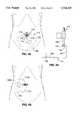
- FIG. 42is a top view of an ninth embodiment of a retraction system according to the invention schematically showing the device connected to a lifting arm and positioned within a lower abdominal region.
- FIG. 43is a side view of the ninth embodiment of FIG. 42.
- FIG. 44is a perspective view of a lifting body of the ninth embodiment of FIG. 42.
- FIG. 45is an exploded view of a lifting body of the ninth embodiment of FIG. 42.
- FIG. 46is a top section view of a lifting body of the ninth embodiment of FIG. 42 taken along the plane designated 46--46 in FIG. 48.
- FIG. 47is a side section view of a lifting body of the ninth embodiment of FIG. 42 showing the lifting body prior to loading.
- FIG. 48is a side section view of a lifting body of the ninth embodiment of FIG. 42 showing the lifting body during loading.
- FIG. 49is a top view of the ninth embodiment with a modified paddle and schematically showing the device laterally positioned within an abdominal region.
- the present inventionprovides a lifting body having retraction rods which are selectively extensible therefrom for supporting the abdominal wall during lifting.
- the inventionwill be described with reference to nine exemplary embodiments.
- FIGS. 1-10show the first embodiment of the present retraction system.
- the first embodimentis comprised of a cylindrical lifting body 10 having proximal and distal portions 16 and 18, respectively.
- the distal portion 18 of the cylindrical lifting bodymay be connected to the proximal portion 16 by a swivel connector (see FIGS. 15-18) which enables the distal portion to swivel about its axis relative to the proximal portion.
- the swivel connectorpreferably has a locking mechanism to prevent swiveling during lifting of the abdominal wall.
- a dovetail connector 14is mounted on the proximal portion 16 for connecting the fan retractor to a lifting bar or holding bar 80 (See FIG. 10).
- the dovetail connectoris constructed to form a positive lock with a dovetail slot formed in a lifting bar adaptor 82 (see FIG. 10).
- cut-out sections 24A and 24Bare substantially perpendicular to the longitudinal axis of the lifting body. As shown in FIG. 3, one cutout section 24A is positioned proximal and lateral of the other cut-out section 24B.
- each cut-out sectionis a mirror-image of the other.
- cut-out section 24Ais comprised of a bore 26A which passes through the cylindrical lifting body, converges towards midline m, and connects with a cut-out triangular section 28A which extends to the perimeter of the cylindrical lifting body.
- the included angle A, shown in FIG. 2, between the bores 26A, 26B of the cut-out sectionsis approximately 120°.
- Each of the retraction rods used with the first embodimentis comprised of a proximal portion 32 and a distal portion 34 joined at an elbow 36.
- the rodsare positioned in the cut-out sections 24A, 24B such that their proximal portions 32 pass through the bores 26a, 26B, and their distal portions 34 are situated within the triangular sections 28a, 28B and extend substantially parallel to each other, away from the cylindrical lifting body.
- the rodsare configured such that they are substantially perpendicular to the longitudinal axis of the cylindrical lifting body when they are not loaded.
- a short vertical portion 35which serves as a handle for use in sliding the rods within the bores.
- the rodsmay have square, oval, or "D"-shaped (see FIG. 7) cross-sections, at least at their proximal portions 32, and the bores 26A, 26B in the cylindrical lifting body have corresponding cross-sections (not shown) which prevent the rods from rotating in the bores.
- the rodsare designed such that they will deform slightly downwards during lifting to conform to the shape of the raised abdomen and to thereby distribute the weight of the abdominal wall along the length of the rods.
- the distal sections of the rodspreferably bend towards each other slightly during lifting so as to distribute the load naturally along the length of the rods.
- the first embodimentallows the surgeon to choose the degree to which the rods will be extended for lifting. Advancing the proximal portions 32 through the cylindrical lifting body 10 as indicated by arrows in FIGS. 1 and 2 causes distal portions 34 to advance further out of the cut-out sections 24A, 24B and to move laterally away from each other.
- the apparatusmay be provided with a locking device which enables the rods to be locked in place after they have been extended to the desired position.
- the rodsare first withdrawn in a proximal direction to position the distal portions 34 immediately adjacent to one another as shown in FIG. 8.
- the proximal portions 32diverge from the bore entrances at the rear of the cylindrical body as shown in FIG. 8.
- the distal portions 34 of the rodsare inserted into a puncture opening BB in the abdominal wall CC at a slightly downward angle.
- the cylindrical body 10is then pivoted upwards to orient the rods such that they are substantially parallel to the horizontal plane.
- the rodsare then advanced through the bores in a distal direction, as indicated by arrows in FIG. 9, causing the distal ends to spread apart while maintaining their parallel relationship.
- the dovetail connector 14is connected to a mechanical lifting arm 80, shown in FIG. 10, which is then raised to elevate the abdominal cavity.
- the D-shaped cross-sections of the boresprevent the similarly shaped rods from rotating during loading.
- FIGS. 11-14A second embodiment is shown in FIGS. 11-14.
- This configurationis asymmetrical in design to allow for distension of the left or right abdominal cavity.
- the cavity-specific configurationis comprised of one fixed, substantially straight, rod 116 and one angular rod 112 which is preferably identical in design to the rods of the first embodiment.
- the straight rod 116is secured within a bore 118 which passes through the cylindrical body in a direction parallel to midline m.
- the angular rod 112is comprised of an angled proximal portion 132 and a straight distal portion 134 joined at an elbow. At the proximal end of the proximal portion 132 is a handle 135. The angled rod 112 is positioned with the proximal portion 132 slidably disposed within a cut-out section in the cylindrical body 110, which may be identical to the section shown in FIG. 5. The cut-out section 124 is positioned proximal and lateral of bore 118.
- the angular rod 112is withdrawn such that its distal portion 134 is close to and parallel with the straight rod as in FIGS. 11-14. After insertion, the angular rod 112 is advanced distally as indicated by arrows in FIGS. 11 and 12 to broaden the gap between the two parallel rods. Phantom lines in FIGS. 12 and 13 illustrate the positioning of angular rod 112 after it has been fully extended.
- FIGS. 15 through 22show additional rod configurations which utilize one fixed rod and one sliding rod.
- a sliding rod 212 and a fixed rod 220each have a substantially straight intermediate portion 222, 224 and an angled distal portion 226, 228.
- Fixed rod 220has a proximal portion 230 that is substantially perpendicular to intermediate portion 224 and that extends generally axially from cylindrical lifting body 210.
- Sliding rod 212has a proximal portion 232 having a first connecting member 234 slidably disposed within a bore (not shown) in the cylindrical body 210.
- a second connecting member 236connects the first connecting member 234 with the intermediate portion 222 of the sliding rod 212.
- the angled distal portion 226 and the intermediate straight portion 222 of the slidable rod 212are parallel to their counterparts 228, 224, respectively, on the fixed rod 220.
- the intermediate straight portion 222 of the slidable rod 212is longer than that of the fixed rod 220.
- Each of the rods 212, 220has a paddle 238, 240 fixed to its distal end. As shown in FIG. 20, each paddle has a substantially straight side 242, 244 and a tapered side 246, 248. The distal end 226 is curved slightly in the downward direction such that paddle 238 of the sliding rod 212 is located slightly below paddle 240 of the fixed rod 220.
- the paddlesare oriented such that they are positioned with their substantially straight sides 242, 244 flat against each other when the slidable rod 212 is positioned in its most proximal position as shown in FIGS. 19 and 20.
- the paddlesare shaped having an elongated cross-section near the distal end to reduce unit load on the patient's tissue and enhance insertion while positioned side by side. It should be noted that it is intended that similar paddles can be used in all embodiments of the invention described herein on load bearing rods, and configured to best suite the particular application intended.
- a bearing 250holds the intermediate straight portions 222, 224 such that they are adjacent and substantially parallel to one another.
- Sliding rod 212is capable of sliding longitudinally within the bearing such that the intermediate straight portions 222, 224 and the angled portions 226, 228 remain substantially parallel to their respective counterpart as in FIG. 15.
- the lifting body 210 of the preferred embodimentis configured to facilitate positioning of the rods prior to lifting by enabling rotation of the lifting rods 212, 220 relative to the lifting body. Because the configuration of the abdominal wall causes an irregular distribution of loading forces on the lifting rods during lifting, the lifting body is further configured to prevent the rods from rotating in response to torsional loading.
- the lifting body 210is comprised of a splined tubular section 216, a keyed column 252, and a base section 218.
- the splined tubular section 216has a throughbore 254 having a splined proximal portion 256.
- a shoulder 258is positioned in the throughbore 254 at the distal end of the tubular section 216.
- a dovetail mount 214is connected to the exterior of the splined tubular section 216 for attachment to a mechanical lifting arm such as the one designated 80 in FIG. 10.
- the keyed column 252 of the lifting body 210is comprised of an elongate column having spaced keys 260 on its proximal section 261.
- the proximal section 261forms a shoulder 266 with a middle section 268 which has a smaller diameter than the proximal section 261.
- Fixed to the distal end of the keyed column 252is a rectangular block 270 which is in turn fixed to the proximal section 230 of fixed rod 220.
- the keyed column 252 of the lifting body 210is proportioned to fit inside the throughbore 254 of the splined tubular section 216 with a compression spring 262 disposed around middle section 266 and supported by shoulder 258 as shown in FIGS. 17 and 18.
- the keyed column 252 and the splined tubular section 216are in turn disposed within a throughbore 264 in base section 218 of the lifting body 210. As shown in FIGS. 17 and 18, when the lifting body 210 is fully assembled, the keyed column 252 and the base section 218 are secured to one another by virtue of the rectangular block 270 of the keyed column 252 which is positioned below a rectangular opening 272 in the base section 218 and secured against a plate 274 surrounding the opening 272.
- the keys 260 of the keyed column 252are positioned proximal of the splined tubular section 216, as shown in FIG. 17.
- the keyed column 252 and the base section 218are capable of rotating jointly about their common longitudinal axis while the splined tubular section 216 remains fixed.
- the base section 218pulls the keyed column 252 such that it moves longitudinally in the distal direction within the throughbore 254 of the splined tubular section 216, causing keys 260 to become engaged with splines 259 on the splined tubular section 216. Engagement of the splines 259 and the keys 260 prevents rotation of the keyed column 252 and base section 218.
- the springserves to allow engagement of the keys 260 and splines 259 only when the tensile force exceeds a minimum level.
- Application of the tensile force between the splined tubular section 216 and the base section 218causes spring 262 to be compressed between shoulders 258 and 266.
- the springis preferably one having a spring constant that will prevent engagement of the keys 260 and splines 259 until the tensile load reaches approximately five pounds.
- the sliding rod 212is positioned in its most proximal position such that the substantially straight sides 242, 244 of paddles 238, 240 are opposing each other as shown in FIG. 20.
- the paddles 238, 240are next inserted into the abdominal cavity.
- a lifting forceis next applied to the lifting body 210 by the lifting arm.
- spring 262will compress sufficiently to cause the keys 260 to engage with the splines 259 and to thereby prevent the rods from rotating out of the desired position during lifting.
- the shapes and angles of the angled portions 238, 240may be configured as required to provide optimal visualization of a particular region of the abdominal cavity.
- the paddle 240A shown in FIG. 21is preferable for use in the upper abdominal region, such as the epigastric region, because its concave curvature mimics the curvature of the rib cage.
- the paddle 240 shown in FIG. 19is preferable for use in the larger lower abdominal region because the paddle shape defines a broad lifting area.
- FIG. 22A fourth embodiment, which is a slight modification of the preferred embodiment is shown in FIG. 22.
- the fourth embodimentutilizes a sliding rod 212A and a fixed rod 220A, each connected to a lifting body 210A and held adjacent to each other by a pair of bearings 250A, 250B.
- the rods 212A, 220Aare provided with handles 252, 254 which assist the user in pushing sliding rod 212A and thereby extending paddle 238A into the abdominal cavity in preparation for lifting.
- each rod 312is comprised of proximal 314 and distal 316 straight portions joined at an approximate right angle.
- a handle 324is provided at the proximal end of each rod.
- Two bores 318, 320pass through the cylindrical body, designated 321, each entering on opposite sides of the cylindrical body 321 and exiting on the bottom face 322 of the cylindrical body as shown in FIG. 25.
- the rodsare positioned with the proximal portions 314 disposed within the bores 318, 320 such that the distal portions 316 are positioned parallel to the bottom face 322 of the cylindrical body 321 and in side-by-side parallel relation with respect to each other as shown in FIG. 25.
- the handles 324are used to advance the proximal portions 314 of the rods towards the cylindrical body, as indicated by arrows in FIG. 23, causing the distal portions 316 to advance from the bottom face 322 of the cylindrical body 321 as shown in FIG. 26, and to move laterally away from one another while maintaining their parallel relationship as shown in FIG. 24.
- each rod 412is comprised of a straight distal portion 414 joined at an approximate right angle to an arcuate proximal portion 416.
- Two bores 418, each having an arcuate path as shown in FIG. 29,pass from opposite sides of the cylindrical body 410 to the bottom face 420 of the cylindrical body.
- the straight distal portions of the rodsare oriented in parallel to the bottom face 420 of the cylindrical body 410 and in side-by-side parallel relation with respect to each other. Advancing the proximal portions 416 of the rods in the direction indicated by arrows in FIG.
- the sixth embodimentmay be configured to ensure simultaneous deployment of the rods.
- a pair of rollers 422, 424may be positioned inside the cylindrical body 410.
- Each rolleris rotatable about a pin 426, 428 passing through its axis. A portion of the perimeter of each roller is in contact with that of the other roller, and a separate portion of the perimeter of each roller is in contact with the arcuate portion 416 of one of the rods.
- the pin 428 passing through the axis of roller 424is connected to a knob 430 positioned on the exterior of the cylindrical body. Turning the knob 430 about its axis rotates the pin and thereby rotates roller 424. Rotation of roller 424 causes roller 426 to rotate due to the contacting portions of their perimeters. Rotation of the rollers 424, 426 causes movement of the rods due to the friction between the perimeters of the rollers and the rods 412.
- FIGS. 31-33This embodiment utilizes a cylindrical body 510 and J-shaped rods 512 each having a straight proximal portion 514 and an arcuate distal portion 516 joined at an elbow 518.
- the cylindrical lifting body 510has two longitudinally oriented slots 520, each on an opposite side of the cylindrical lifting body from the other. Each slot 520 passes through the distal face 522 of the cylindrical lifting body, and a peg 524 crosses the distal end of each slot 520.
- the rods 512are positioned with their elbows 518 disposed within the distal portion of the slot 520 such that the rods 512 are pivotable around the pegs 524.
- the straight proximal portions 514 of the rods 512extend laterally from the cylindrical lifting body.
- the arcuate distal portions 516 of the rodsextend through the distal ends of the slots 520 from the bottom face 522 of the cylindrical body 510 and are in side-by-side parallel relationship with each other, allowing the distal portions 516 of the rods 512 to be inserted into the abdominal cavity using a hooking motion.
- the rods 512are deployed into the lifting position by moving the straight proximal portions 514 into the slots as indicated by arrows in FIGS. 31 and 33, thereby pivoting the rods around their elbows 518.
- the arcuate distal portions 516are thereby pivoted laterally as indicated by arrows in FIGS. 31 and 33 to form the substantially circular lifting area 528 shown in FIG. 32.
- Rods 516can alternatively be fabricated to be insertable into the abdominal cavity while perpendicular to lifting body 510, with one rod pivoting 180° to create the circular lifting area 528.
- an inflatable envelope(preferably an elastic or inelastic balloon) is secured to lifting body 510 near distal face 522 to retract surrounding tissue and provide an unobstructed path for deployment of pivoting rods 516.
- Such an envelopefurther serves as a supporting membrane across rods 516 when in the deflated state as rods 516 are deployed laterally, thereby preventing tissue from sagging between the rods.
- the lifting bodyis cubical and has a variety of bores which allow the surgeon to fashion a rod configuration which will provide the most satisfactory visualization of the organs to be treated.
- this alternative embodimentis comprised generally of a lifting body 610 mounted to the distal portion of a handle 614, retraction rods 612 for insertion into bores 616,618 in the lifting body 610, and a lifting grip 620 positioned at the proximal portion of the handle 614.
- the lifting body 610is preferably cubic, although lifting bodies of various shapes are possible. Its size and shape are limited by a number of factors. During use, the lifting body will normally be placed in the abdominal cavity AA, FIG. 34, through a puncture opening or small incision BB and therefore should preferably be approximately 10-20 mm in length. Moreover, as will be described below, the lifting body 610 will be used to lift a portion of the abdominal wall CC. The upper face 622 of the lifting body 610 should thus have adequate surface area and geometry to accomplish this lifting without tearing or traumatizing the surrounding tissue.
- bores 616, 618pass through the body from its rear face 624 to its forward face 626, lower face 628, and side faces 630.
- the bores 616 which will be used for lifting the abdominal wallare approximately parallel with the plane of the upper face 622 of the lifting body (i.e. parallel to the horizontal plane) so as to allow for even loading of the retraction rods inserted through the bores 616.
- These boresare intended to receive rods which will exert lifting forces on the abdominal wall. It is preferable to have these bores passing through the side faces 630 of the lifting body as shown in FIG.
- a selection of bores having various orientationsmay be provided to enable to surgeon to choose the configuration of rods that is most suitable for the size of the patient and the necessary amount of work space.
- bores 618angle downward and pass through the lower portion of the forward face 626 of the lifting body. These are intended to receive rods which will be used for retracting abdominal organs or other tissue within or surrounding the abdominal cavity (collectively referred to herein as "abdominal organs") out of the way of the work space as described below. Bores which pass through the lower face 628 of the lifting body may also be provided.
- Various surgical procedureswill require downward angles of varying degrees. For example, retraction of the liver requires a downward angle of approximately 45° from a horizontal plane while retraction of the bowel requires a downward angle of approximately 60°-70° from the horizontal plane.
- a dovetail connector 632which is provided for connecting the fan retractor to a lifting bar or holding bar 80. (See FIG. 34.)
- the proximal portion of the handle 614is formed into a lifting grip 620.
- the grip 620provides a means for manipulating and temporarily lifting the lifting body and the portion of the abdominal wall surrounding it while the retraction rods are being inserted into the lifting body.
- each rod 612has an insertion end 644 for insertion through the bores 616,618 and into the abdominal cavity AA, and a stabilizing end 646 which extends laterally from the rod.
- the stabilizing end 646is incapable of entering the bores and thereby prevents the rod 612 from falling into the abdominal cavity.
- Retraction rods of differing lengthsmay be configured to provide retraction of abdominal organs located at varying distances from the lifting body.
- Rods for retracting the abdominal wallmay be approximately 4-6" in length, while rods of approximately 10" in length may be needed for retracting the bowel, liver, and other organs.
- Long rods(not shown) may be constructed with adjustable stabilizing devices which allow the surgeon to choose the depth to which a longer retraction rod may be inserted and to lock the retraction rod in position against the rear face 624 of the body once it has reached the desired depth.
- the rodsmay be constructed to taper slightly from the insertion end to the stabilizing end to facilitate movement of the rods as they pass into the abdominal cavity.
- the stiffness of the rods in the lifting directioni.e., in the direction of the lifting handle, may be made to decrease distally from the stabilizing end. Distally reducing the stiffness of the rods enables them to bend to conform to the shape of the raised abdomen while having sufficient strength to provide the lifting force necessary. This spreads the lifting force evenly along the length of the rods instead of concentrating the lifting force towards their distal ends.
- Rods which may be expanded once they are inserted into the abdominal cavitymay also be configured. Such a construction may be used to lock the rods within the bores at select positions relative to the body.
- a balloon tipped retractor 612Ahaving a hollow cannula 648 with an inflatable balloon 650 attached at its distal end and a valve 652 at its proximal end may be used for organ retraction.
- An incision or trocar puncture BBis made in a suitable location in the abdominal wall.
- the lifting body 610is inserted into the incision and positioned under the abdominal wall adjacent to the incision as shown in FIG. 39.
- the handle 614is held such that it protrudes from the incision in a direction normal to the abdominal wall.
- a lifting forceis applied manually to the lifting grip 620 so that the lifting body 610 pulls the abdominal wall slightly upward in the direction of the lifting force.
- the entrances to the bores, which are at the rear face 624 of the lifting bodyare thus lifted above the incision.
- Retraction rods 612are individually advanced through selected bores by inserting the insertion ends 644 of the retraction rods into the bores 616 from the rear face 624 of the lifting body and advancing them into the abdominal cavity AA such that they are in contact with the interior surface of the abdominal wall DD.
- the retraction rods 612should be advanced until their stabilizing ends 646 abut the rear face 624 of the handle 614, preventing them from advancing further.
- the handleis next connected at the dovetail connector 632 to a mechanical lifting device.
- the mechanical lifting deviceapplies additional lifting force to the handle 614 as shown by arrows in FIG. 40, thereby raising the abdominal wall by causing the retraction rods 612 to push the abdominal wall from inside the abdominal cavity.
- additional retraction rodssuch as the balloon retractor 612A may be inserted at downwardly-directed bore holes 618 so as to retract abdominal organs away from the surgeon's work space.
- the valve 652is connected to a source of inflation gas, such as air or carbon dioxide, and gas is allowed to flow into the balloon 650 through the cannula 648 until the balloon is inflated as desired.
- FIGS. 42 through 49A ninth alternative embodiment is shown in FIGS. 42 through 49.
- This embodimentis comprised of a pair of lifting bodies 710 positioned in side-by-side relationship on a pair of dovetail mounts 715 connected to a dovetail wrist 714 for connecting the bodies to a lifting arm 80 (see FIG. 10), and a pair of lifting rods 712 suspended from the lifting bodies 710.
- each retraction rod 712is comprised of a connecting member 718, a retracting portion 720, and a substantially vertical support portion 722 connecting the two.
- the connecting member 718is secured within a bore at a base 724 of a support column 726.
- the retracting portion 720is substantially parallel to the connecting member 718.
- each retracting portion 720is formed into a paddle 728.
- the retracting portions 720are shaped such that when the apparatus is fully assembled for lifting, the region defined by the retracting portions 720 is approximately diamond-shaped as shown in FIG. 42. This shape, as well as the other shapes previously disclosed, is intended to profile the natural shape of the particular body cavity and surrounding anatomic features.
- each lifting body 710is comprised of a cylindrical body 708 having a throughbore 716 and a compression spring 736 positioned in engagement with a shoulder 738 in the throughbore 716.
- Spaced keys 739are secured to the cylindrical body 708 within the throughbore 716 and extend into the throughbore as shown in FIG. 47.
- Each support column 726is comprised of an elongate member of circular cross-section proportioned for insertion through the throughbore 716 in the lifting body such that the spring 736 is disposed around it.
- a proximal head 730 of the support column 726is a reduced-diameter portion 732 having a square cross-sect/on. Because the reduced-diameter portion 732 is cut out of the relatively wider support column 726, a ridge 749 is formed at the base of the reduced-diameter portion 732.
- the support columnalso has a locking ring 734 slidably disposed around it at a position distal of the reduced diameter portion 732.
- the lifting body 710further comprises a splined column cap 740 having spaced splines 742 extending longitudinally on the column cap 740.
- the column cap 740is cylindrical and has squared 744 and rounded 746 cut-out portions which form a continuous passage longitudinally through it and which extend laterally to give the column cap a substantially C-shaped cross-section as shown in FIG. 46.
- the diameter of the rounded cut-out portion 746is slightly greater than that of the squared cut-out portion 744 such that a shoulder 748 is formed between them.
- the squared cut-out portion 744is proportioned to mate with the squared, reduced diameter portion 732 of the support column 726.
- the support column 726is inserted through the throughbore 716 of the cylindrical body 708 such that the spring 736 is disposed around it and such that the squared reduced diameter portion 732 protrudes proximally of the cylindrical body 708.
- the splined column cap 740is positioned around the support column 726 with its squared cut-out portion 744 engaged with the squared portion 732 of the support column 726 beneath the head 730 such that shoulder 748 of the splined column cap 742 is supported by the ridge 749 on the support column 732.
- Joining the squared cross-sections of the support column 726 and the splined column cap 740causes these components to be keyed together and thus incapable of rotating relative to each other.
- Engaging the column cap 740 with the support column as described abovecauses the column cap 740 to be disposed partially within the throughbore 716 of the cylindrical body 708 near the proximal end of the lifting body 710 such that its distal end is supported by the spring 736 slightly above the level of the keys 739.
- the keysare positioned distal of the splined column cap, in the longitudinal direction.
- the keys and the splinesare not engaged with each other and thus allow for the splined column cap 740 and support column 726 to be rotated as a single unit about their common longitudinal axis.
- the lifting armis positioned such that it hovers slightly above a puncture opening in an abdominal cavity as shown in FIG. 42.
- the dovetail mounts 715are attached to dovetail wrist 714 which is then attached to a dovetail connector on the lifting arm 80 (see FIG. 10).
- Each paddle 728is separately inserted into the puncture opening in the abdominal cavity and its respective support column 726 is subsequently inserted longitudinally into one of the cylindrical bodies 708 and held within the cylindrical body using the splined column cap 740 as described above.
- the splined column cap and the support columnare next rotated about their column longitudinal axis until the paddles 728 are in the desired position within the abdominal cavity.
- the lifting arm 80is then raised to lift the abdominal wall.
- the design of the lifting body 710is such that the paddles may be rotated into the desired orientation prior to lifting and then secured against further rotation after a lifting force is applied.
- a tensile forceis applied to the apparatus in the direction indicated by arrows in FIG. 48, the support column 726 pulls down on the splined column cap 740.
- the loading on the splined column cap 740causes it to move longitudinally within the cylindrical body 708 and to thereby compress the compression spring 736.
- the splined column cap 740advances far enough in the longitudinal direction for each of the keys positioned within the throughbore 716 in the lifting body to mate with a spline 742 on the exterior of the splined column cap 740.
- the lock caused by the mating of the keys and the splinesprevents rotation of the splined column cap about its longitudinal axis and thus prevents rotation of the support column which is fixed to the splined column cap.
- any torsional force caused by the pull of the abdominal wall on the paddles 728 during liftingwill not rotate the paddles out of position.
- the locking ring 734(FIG. 45) may be advanced along the support column 726 towards the cylindrical body 708 until it is positioned just below the cylindrical body with the cylindrical body supported by it. Doing so locks the relative positioning of the support column 726 and the cylindrical body 708 so as to maintain engagement of the splines and the keys to prevent rotation of the paddies 728 even when no load is applied to the apparatus.
- the retraction rodsmay be configured in varying shapes so as to enable appropriate shapes to be chosen for particular procedures. For example, as shown in FIG. 49, in certain procedures, such as those requiring retraction of the lateral portion of the abdominal wall, rods 712, 712A having differing shapes may be used.
Landscapes
- Health & Medical Sciences (AREA)
- Life Sciences & Earth Sciences (AREA)
- Surgery (AREA)
- Molecular Biology (AREA)
- General Health & Medical Sciences (AREA)
- Biomedical Technology (AREA)
- Heart & Thoracic Surgery (AREA)
- Medical Informatics (AREA)
- Nuclear Medicine, Radiotherapy & Molecular Imaging (AREA)
- Animal Behavior & Ethology (AREA)
- Engineering & Computer Science (AREA)
- Public Health (AREA)
- Veterinary Medicine (AREA)
- Oral & Maxillofacial Surgery (AREA)
- Pathology (AREA)
- Surgical Instruments (AREA)
- Endoscopes (AREA)
Abstract
Description
Claims (19)
Priority Applications (1)
| Application Number | Priority Date | Filing Date | Title |
|---|---|---|---|
| US08/671,828US5716327A (en) | 1991-05-29 | 1996-06-25 | Body wall retraction system for wide cavity retraction |
Applications Claiming Priority (6)
| Application Number | Priority Date | Filing Date | Title |
|---|---|---|---|
| US70678191A | 1991-05-29 | 1991-05-29 | |
| US89003392A | 1992-05-28 | 1992-05-28 | |
| US08/062,707US5520609A (en) | 1991-05-29 | 1993-05-18 | Apparatus and method for peritoneal retraction |
| US12847793A | 1993-09-28 | 1993-09-28 | |
| US40810295A | 1995-03-21 | 1995-03-21 | |
| US08/671,828US5716327A (en) | 1991-05-29 | 1996-06-25 | Body wall retraction system for wide cavity retraction |
Related Parent Applications (2)
| Application Number | Title | Priority Date | Filing Date |
|---|---|---|---|
| US08/062,707Continuation-In-PartUS5520609A (en) | 1991-05-29 | 1993-05-18 | Apparatus and method for peritoneal retraction |
| US40810295AContinuation | 1991-05-29 | 1995-03-21 |
Publications (1)
| Publication Number | Publication Date |
|---|---|
| US5716327Atrue US5716327A (en) | 1998-02-10 |
Family
ID=27535588
Family Applications (1)
| Application Number | Title | Priority Date | Filing Date |
|---|---|---|---|
| US08/671,828Expired - LifetimeUS5716327A (en) | 1991-05-29 | 1996-06-25 | Body wall retraction system for wide cavity retraction |
Country Status (1)
| Country | Link |
|---|---|
| US (1) | US5716327A (en) |
Cited By (45)
| Publication number | Priority date | Publication date | Assignee | Title |
|---|---|---|---|---|
| US5941819A (en)* | 1991-05-29 | 1999-08-24 | Origin Medsystems, Inc. | Apparatus for creating a mediastinal working space |
| US6042539A (en)* | 1999-03-26 | 2000-03-28 | Ethicon Endo-Surgery, Inc. | Vacuum-actuated tissue-lifting device and method |
| WO2006010919A1 (en)* | 2004-07-27 | 2006-02-02 | Imperial Innovations Limited | A device |
| US20060122580A1 (en)* | 2004-12-08 | 2006-06-08 | Patrick Dannan | Tool insertion device for use in minimally invasive surgery |
| US20060247516A1 (en)* | 2005-04-08 | 2006-11-02 | Hess Christopher J | Tissue marker and method for use |
| US20070213675A1 (en)* | 2006-03-13 | 2007-09-13 | Applied Medical Resources Corporation | Balloon trocar |
| US20070239108A1 (en)* | 2006-03-13 | 2007-10-11 | Applied Medical Resources Corporation | Balloon trocar |
| US20080004644A1 (en)* | 2006-06-30 | 2008-01-03 | Atheromed, Inc. | Atherectomy devices and methods |
| US20080004646A1 (en)* | 2006-06-30 | 2008-01-03 | Atheromed, Inc. | Atherectomy devices and methods |
| US20080004647A1 (en)* | 2006-06-30 | 2008-01-03 | Atheromed, Inc. | Atherectomy devices and methods |
| US20080045986A1 (en)* | 2006-06-30 | 2008-02-21 | Atheromed, Inc. | Atherectomy devices and methods |
| US20090018566A1 (en)* | 2006-06-30 | 2009-01-15 | Artheromed, Inc. | Atherectomy devices, systems, and methods |
| US20090018567A1 (en)* | 2006-06-30 | 2009-01-15 | Artheromed, Inc. | Atherectomy devices, systems, and methods |
| US20090062618A1 (en)* | 2007-08-29 | 2009-03-05 | Ethicon Endo-Surgery, Inc. | Tissue retractors |
| US20090069627A1 (en)* | 2005-11-11 | 2009-03-12 | Hans Haindl | Device for supporting the abdominal wall relative to underlying organs during minimally invasive surgery |
| US20090137877A1 (en)* | 2007-11-26 | 2009-05-28 | Ethicon Endo-Surgery, Inc. | Tissue retractors |
| US20090137984A1 (en)* | 2007-11-26 | 2009-05-28 | Ethicon Endo-Surgery, Inc. | Tissue retractors |
| US20090234378A1 (en)* | 2007-10-22 | 2009-09-17 | Atheromed, Inc. | Atherectomy devices and methods |
| US20100228096A1 (en)* | 2009-03-06 | 2010-09-09 | Ethicon Endo-Surgery, Inc. | Methods and devices for providing access into a body cavity |
| US20100228090A1 (en)* | 2009-03-06 | 2010-09-09 | Ethicon Endo-Surgery, Inc. | Methods and devices for providing access into a body cavity |
| US20100249516A1 (en)* | 2006-04-05 | 2010-09-30 | Shelton Iv Frederick E | Access Device |
| US20100249525A1 (en)* | 2009-03-31 | 2010-09-30 | Ethicon Endo-Surgery, Inc. | Devices and methods for providing access into a body cavity |
| US20100261975A1 (en)* | 2009-03-06 | 2010-10-14 | Ethicon Endo-Surgery, Inc. | Methods and devices for accessing a body cavity |
| US20110028793A1 (en)* | 2009-07-30 | 2011-02-03 | Ethicon Endo-Surgery, Inc. | Methods and devices for providing access into a body cavity |
| US20110066001A1 (en)* | 2009-03-31 | 2011-03-17 | Shelton Iv Frederick E | Access Method With Insert |
| US20110082345A1 (en)* | 2009-10-02 | 2011-04-07 | Wilson-Cook Medical Inc. | Apparatus for single port access |
| US20110112563A1 (en)* | 2006-06-30 | 2011-05-12 | Atheromed, Inc. | Atherectomy devices and methods |
| US8236016B2 (en) | 2007-10-22 | 2012-08-07 | Atheromed, Inc. | Atherectomy devices and methods |
| US8460337B2 (en) | 2010-06-09 | 2013-06-11 | Ethicon Endo-Surgery, Inc. | Selectable handle biasing |
| US8562592B2 (en) | 2010-05-07 | 2013-10-22 | Ethicon Endo-Surgery, Inc. | Compound angle laparoscopic methods and devices |
| US8628549B2 (en) | 2006-06-30 | 2014-01-14 | Atheromed, Inc. | Atherectomy devices, systems, and methods |
| US8795306B2 (en) | 2011-10-13 | 2014-08-05 | Atheromed, Inc. | Atherectomy apparatus, systems and methods |
| US8888692B1 (en) | 2011-08-26 | 2014-11-18 | Applied Medical Resources Corporation | Trocar cannula assembly and method of manufacture |
| US9169961B1 (en) | 2011-01-24 | 2015-10-27 | Jeng-Kai Jiang | Lifting apparatus for gasless laparoscopic surgery |
| US9226760B2 (en) | 2010-05-07 | 2016-01-05 | Ethicon Endo-Surgery, Inc. | Laparoscopic devices with flexible actuation mechanisms |
| US9333001B2 (en) | 2009-10-08 | 2016-05-10 | Ethicon Endo-Surgery, Inc. | Articulable laparoscopic instrument |
| US9492192B2 (en) | 2006-06-30 | 2016-11-15 | Atheromed, Inc. | Atherectomy devices, systems, and methods |
| US9522265B2 (en) | 2013-03-15 | 2016-12-20 | Applied Medical Resources Corporation | Trocar cannula assembly with low profile insertion configuration and method of manufacture |
| US10076239B2 (en) | 2009-10-02 | 2018-09-18 | Cook Medical Technologies Llc | Port access visualization platform |
| WO2019236027A3 (en)* | 2018-02-21 | 2020-01-16 | Orhan Seyfi Aksakal | A retractor system |
| US11207096B2 (en) | 2006-06-30 | 2021-12-28 | Atheromed, Inc. | Devices systems and methods for cutting and removing occlusive material from a body lumen |
| US11304723B1 (en) | 2020-12-17 | 2022-04-19 | Avantec Vascular Corporation | Atherectomy devices that are self-driving with controlled deflection |
| US12220140B1 (en) | 2023-08-16 | 2025-02-11 | Avantec Vascular Corporation | Thrombectomy devices with lateral and vertical bias |
| US12290279B2 (en) | 2021-06-07 | 2025-05-06 | Avantec Vascular Corporation | Hybrid atherectomy devices |
| US12414785B1 (en) | 2025-03-17 | 2025-09-16 | Avantec Vascular Corporation | Cutters with pulsating vacuum control |
Citations (99)
| Publication number | Priority date | Publication date | Assignee | Title |
|---|---|---|---|---|
| US1060350A (en)* | 1911-12-18 | 1913-04-29 | Robert E L Miller | Intestine-protector. |
| US1275520A (en)* | 1917-06-14 | 1918-08-13 | William L Bell | Gauze-dam surgical instrument. |
| US1618261A (en)* | 1927-02-22 | Viscera retainer for use in abdominal operations | ||
| US1798124A (en)* | 1929-08-15 | 1931-03-24 | Josiah Brinkerhoff | Urethral sound and axis-traction prostatic retractor |
| US1947649A (en)* | 1931-12-05 | 1934-02-20 | Godfrey J Kadavy | Surgical instrument |
| US2663020A (en)* | 1950-12-20 | 1953-12-22 | Cecil A Cushman | Pneumatic injury pad |
| US2841148A (en)* | 1957-06-21 | 1958-07-01 | Godfrey J Kadavy | Viscera retainer for use in abdominal operations |
| US3039468A (en)* | 1959-01-07 | 1962-06-19 | Joseph L Price | Trocar and method of treating bloat |
| DE1516411A1 (en)* | 1966-03-04 | 1969-07-24 | Albert Hauber | Dismountable belly spatula |
| US3460539A (en)* | 1967-03-10 | 1969-08-12 | James E Anhalt Sr | Cautery tip |
| US3626949A (en)* | 1969-01-23 | 1971-12-14 | Wallace B Shute | Cervical dilator |
| US3631859A (en)* | 1970-03-06 | 1972-01-04 | William Gayle Crutchfield | An instrument for use in the treatment of intracranial vascular disorders |
| US3717151A (en)* | 1971-03-11 | 1973-02-20 | R Collett | Flesh penetrating apparatus |
| US3774596A (en)* | 1971-06-29 | 1973-11-27 | G Cook | Compliable cavity speculum |
| US3782370A (en)* | 1972-07-12 | 1974-01-01 | B Mcdonald | Surgical retractor |
| US3831587A (en)* | 1973-02-08 | 1974-08-27 | Mc Anally R | Multipurpose vaginal and cervical device |
| US3863639A (en)* | 1974-04-04 | 1975-02-04 | Richard N Kleaveland | Disposable visceral retainer |
| US3868957A (en)* | 1973-10-03 | 1975-03-04 | Regents State Of Florida Board | Vascular clamp |
| US3961632A (en)* | 1974-12-13 | 1976-06-08 | Moossun Mohamed H | Stomach intubation and catheter placement system |
| US4052980A (en)* | 1976-06-10 | 1977-10-11 | Guenter A. Grams | Triaxial fiberoptic soft tissue retractor |
| US4083369A (en)* | 1976-07-02 | 1978-04-11 | Manfred Sinnreich | Surgical instruments |
| DE2847633A1 (en)* | 1977-11-04 | 1979-05-10 | Olympus Optical Co | Gallstone removal balloon catheter - is introduced through endoscope, with balloon mounted on ends of flexible telescopic tubes |
| US4183102A (en)* | 1977-09-08 | 1980-01-15 | Jacques Guiset | Inflatable prosthetic device for lining a body duct |
| EP0010650A1 (en)* | 1978-10-10 | 1980-05-14 | BioNexus, Inc. | Instrument for dispensing material into the Fallopian tubes |
| US4240433A (en)* | 1977-07-22 | 1980-12-23 | Bordow Richard A | Fluid aspiration device and technique for reducing the risk of complications |
| SU797668A1 (en) | 1978-06-13 | 1981-01-23 | Петрозаводский Государственныйуниверситет Им. O.B.Куусинена | Device for limiting surgery field on small pelvis |
| US4254762A (en)* | 1979-10-23 | 1981-03-10 | Inbae Yoon | Safety endoscope system |
| AU516114B2 (en)* | 1977-03-29 | 1981-05-21 | Frank Baskind Allen | Apparatus for obtaining oytological specimens |
| FR2474304A1 (en)* | 1979-12-13 | 1981-07-31 | Air Foundation | Instrument for pneumatic removal of live tissue e.g. tumour - has hollow handle and shaft with articulated tip directing pressurised fluid at tissue |
| US4291687A (en)* | 1978-03-02 | 1981-09-29 | Manfred Sinnreich | Inflatable packing for surgical use having auxiliary intestinal supporting member |
| US4357940A (en)* | 1979-12-13 | 1982-11-09 | Detroit Neurosurgical Foundation | Tissue pneumatic separator structure |
| US4430076A (en)* | 1982-02-04 | 1984-02-07 | Harris James H | Combined uterine injector and manipulative device |
| US4447227A (en)* | 1982-06-09 | 1984-05-08 | Endoscopy Surgical Systems, Inc. | Multi-purpose medical devices |
| US4459978A (en)* | 1982-05-17 | 1984-07-17 | Endoscopy Surgical Systems, Inc. | Medical retractor device |
| US4502485A (en)* | 1977-06-30 | 1985-03-05 | Burgin Kermit H | Plastic forceps |
| DE8516296U1 (en)* | 1985-06-04 | 1985-08-08 | Wenzler, Günther, 7201 Balgheim | Retractor |
| US4535773A (en)* | 1982-03-26 | 1985-08-20 | Inbae Yoon | Safety puncturing instrument and method |
| US4572179A (en)* | 1981-08-21 | 1986-02-25 | Teitelbaum Jay M | Apparatus for removing swine tails |
| US4598699A (en)* | 1985-06-10 | 1986-07-08 | Garren Lloyd R | Endoscopic instrument for removing stomach insert |
| US4601710A (en)* | 1983-08-24 | 1986-07-22 | Endotherapeutics Corporation | Trocar assembly |
| US4654030A (en)* | 1986-02-24 | 1987-03-31 | Endotherapeutics | Trocar |
| US4662955A (en)* | 1985-10-09 | 1987-05-05 | The United States Of America As Represented By The Administrator Of The National Aeronautics And Space Administration | Method of thermal strain hysteresis reduction in metal matrix composites |
| DE3600789A1 (en)* | 1986-01-14 | 1987-07-16 | Georg Dr Med Kesimidis | Intestinal forceps |
| US4693243A (en)* | 1983-01-14 | 1987-09-15 | Buras Sharon Y | Conduit system for directly administering topical anaesthesia to blocked laryngeal-tracheal areas |
| US4705040A (en)* | 1985-11-18 | 1987-11-10 | Medi-Tech, Incorporated | Percutaneous fixation of hollow organs |
| EP0246086A2 (en)* | 1986-05-14 | 1987-11-19 | Aldo Sergio Kleiman | A procedure for carrying out a surgical operation and a retracting laparoscope for separating organs in surgery |
| US4709697A (en)* | 1980-12-09 | 1987-12-01 | Joseph J. Berke | Tissue pneumatic separator structure and method |
| EP0251976A2 (en)* | 1986-06-05 | 1988-01-07 | Fogarty, Thomas J. | Shear force gauge and method and apparatus for limiting embolectomy shear force |
| US4744363A (en)* | 1986-07-07 | 1988-05-17 | Hasson Harrith M | Intra-abdominal organ stabilizer, retractor and tissue manipulator |
| EP0275230A2 (en)* | 1987-01-15 | 1988-07-20 | FOGARTY, Thomas J. | Catheter with corkscrew-like balloon |
| US4763635A (en)* | 1985-05-30 | 1988-08-16 | Robert Bosch Gmbh | Discharge system for introducing volatilized fuel into an internal combustion engine |
| US4765331A (en)* | 1987-02-10 | 1988-08-23 | Circon Corporation | Electrosurgical device with treatment arc of less than 360 degrees |
| US4775371A (en)* | 1986-09-02 | 1988-10-04 | Advanced Cardiovascular Systems, Inc. | Stiffened dilatation catheter and method of manufacture |
| US4779611A (en)* | 1987-02-24 | 1988-10-25 | Grooters Ronald K | Disposable surgical scope guide |
| US4919152A (en)* | 1987-03-02 | 1990-04-24 | Ralph Ger | Method of closing the opening of a hernial sac |
| US4944443A (en)* | 1988-04-22 | 1990-07-31 | Innovative Surgical Devices, Inc. | Surgical suturing instrument and method |
| FR2646088A1 (en)* | 1989-04-19 | 1990-10-26 | Ruiz Razura Amado | INFLATABLE ENVELOPE FOR ELONGATION OF BIOLOGICAL TISSUES |
| US4966583A (en)* | 1989-02-03 | 1990-10-30 | Elie Debbas | Apparatus for locating a breast mass |
| US4984564A (en)* | 1989-09-27 | 1991-01-15 | Frank Yuen | Surgical retractor device |
| US5002557A (en)* | 1989-04-06 | 1991-03-26 | Hasson Harrith M | Laparoscopic cannula |
| US5007898A (en)* | 1988-06-02 | 1991-04-16 | Advanced Surgical Intervention, Inc. | Balloon dilatation catheter |
| US5014407A (en)* | 1989-09-28 | 1991-05-14 | Boughten Larry R | Tube expanding device |
| DE9102759U1 (en)* | 1991-03-08 | 1991-05-29 | Storz, Karl, Dr.med.h.c., 7200 Tuttlingen | Retractor |
| DE9104383U1 (en)* | 1991-04-10 | 1991-06-06 | Wisap Gesellschaft für wissenschaftlichen Apparatebau mbH, 8029 Sauerlach | Abdominal cavity expander |
| EP0449663A2 (en)* | 1990-03-29 | 1991-10-02 | United States Surgical Corporation | Abdominal cavity organ retractor |
| US5062847A (en)* | 1990-12-31 | 1991-11-05 | Barnes William E | Laparoscopic retractor |
| EP0464463A1 (en)* | 1990-07-03 | 1992-01-08 | Richard Wolf GmbH | Organ manipulator |
| US5082005A (en)* | 1990-12-18 | 1992-01-21 | New England Deaconess Hospital | Surgical access device |
| US5100426A (en)* | 1989-07-26 | 1992-03-31 | Fts Engineering, Inc. | Catheter for performing an atherectomy procedure |
| DE9202305U1 (en)* | 1992-02-22 | 1992-04-23 | Meyer, Hans-Joachim, Dr.med., 5960 Olpe | Probe for minimally invasive surgery |
| US5122155A (en)* | 1990-10-11 | 1992-06-16 | Eberbach Mark A | Hernia repair apparatus and method of use |
| US5122122A (en)* | 1989-11-22 | 1992-06-16 | Dexide, Incorporated | Locking trocar sleeve |
| US5133724A (en)* | 1991-04-04 | 1992-07-28 | Pilling Co. | Abdominal aortic clamp |
| US5141515A (en)* | 1990-10-11 | 1992-08-25 | Eberbach Mark A | Apparatus and methods for repairing hernias |
| US5152279A (en)* | 1991-11-15 | 1992-10-06 | Wilk Peter J | Retractor and associated method for use in laparoscopic surgery |
| US5163949A (en)* | 1990-03-02 | 1992-11-17 | Bonutti Peter M | Fluid operated retractors |
| US5176128A (en)* | 1991-01-24 | 1993-01-05 | Andrese Craig A | Organ retractor |
| US5176697A (en)* | 1989-04-06 | 1993-01-05 | Hasson Harrith M | Laparoscopic cannula |
| US5176692A (en)* | 1991-12-09 | 1993-01-05 | Wilk Peter J | Method and surgical instrument for repairing hernia |
| US5183033A (en)* | 1991-07-15 | 1993-02-02 | Wilk Peter J | Surgical instrument assembly and apparatus and surgical method |
| US5183463A (en)* | 1989-02-03 | 1993-02-02 | Elie Debbas | Apparatus for locating a breast mass |
| US5183464A (en)* | 1991-05-17 | 1993-02-02 | Interventional Thermodynamics, Inc. | Radially expandable dilator |
| US5188630A (en)* | 1991-03-25 | 1993-02-23 | Christoudias George C | Christoudias endospongestick probe |
| EP0531710A2 (en)* | 1991-08-05 | 1993-03-17 | United States Surgical Corporation | Endoscopic dilator |
| US5195506A (en)* | 1991-10-18 | 1993-03-23 | Life Medical Products, Inc. | Surgical retractor for puncture operation |
| US5195507A (en)* | 1990-11-06 | 1993-03-23 | Ethicon, Inc. | Endoscopic surgical instrument for displacing tissue or organs |
| US5195505A (en)* | 1990-12-27 | 1993-03-23 | United States Surgical Corporation | Surgical retractor |
| US5197948A (en)* | 1991-01-03 | 1993-03-30 | Kamran Ghodsian | Intra-abdominal organ manipulator, irrigator and aspirator |
| US5209747A (en)* | 1990-12-13 | 1993-05-11 | Knoepfler Dennis J | Adjustable angle medical forceps |
| FR2688695A1 (en)* | 1992-03-20 | 1993-09-24 | Bogdanoff Joseph | Medical mattress |
| US5250074A (en)* | 1992-07-14 | 1993-10-05 | Wilk Peter J | Surgical instrument assembly and associated technique |
| US5254130A (en)* | 1992-04-13 | 1993-10-19 | Raychem Corporation | Surgical device |
| US5269753A (en)* | 1992-07-14 | 1993-12-14 | Wilk Peter J | Method for use in laparoscopic hernia repair |
| US5271385A (en)* | 1990-03-29 | 1993-12-21 | United States Surgical Corporation | Abdominal cavity organ retractor |
| US5275608A (en)* | 1991-10-16 | 1994-01-04 | Implemed, Inc. | Generic endoscopic instrument |
| US5280782A (en)* | 1991-11-15 | 1994-01-25 | Wilk Peter J | Variable length laparoscopic retractor and associated method of use |
| US5284130A (en)* | 1992-06-03 | 1994-02-08 | Ratliff Jack L | Surgical instrument positioning and securing apparatus |
| US5289817A (en)* | 1991-08-20 | 1994-03-01 | Linvatec Corporation | Endoscopic surgical retractor |
| US5330502A (en)* | 1992-10-09 | 1994-07-19 | Ethicon, Inc. | Rotational endoscopic mechanism with jointed drive mechanism |
- 1996
- 1996-06-25USUS08/671,828patent/US5716327A/ennot_activeExpired - Lifetime
Patent Citations (102)
| Publication number | Priority date | Publication date | Assignee | Title |
|---|---|---|---|---|
| US1618261A (en)* | 1927-02-22 | Viscera retainer for use in abdominal operations | ||
| US1060350A (en)* | 1911-12-18 | 1913-04-29 | Robert E L Miller | Intestine-protector. |
| US1275520A (en)* | 1917-06-14 | 1918-08-13 | William L Bell | Gauze-dam surgical instrument. |
| US1798124A (en)* | 1929-08-15 | 1931-03-24 | Josiah Brinkerhoff | Urethral sound and axis-traction prostatic retractor |
| US1947649A (en)* | 1931-12-05 | 1934-02-20 | Godfrey J Kadavy | Surgical instrument |
| US2663020A (en)* | 1950-12-20 | 1953-12-22 | Cecil A Cushman | Pneumatic injury pad |
| US2841148A (en)* | 1957-06-21 | 1958-07-01 | Godfrey J Kadavy | Viscera retainer for use in abdominal operations |
| US3039468A (en)* | 1959-01-07 | 1962-06-19 | Joseph L Price | Trocar and method of treating bloat |
| DE1516411A1 (en)* | 1966-03-04 | 1969-07-24 | Albert Hauber | Dismountable belly spatula |
| US3460539A (en)* | 1967-03-10 | 1969-08-12 | James E Anhalt Sr | Cautery tip |
| US3626949A (en)* | 1969-01-23 | 1971-12-14 | Wallace B Shute | Cervical dilator |
| US3631859A (en)* | 1970-03-06 | 1972-01-04 | William Gayle Crutchfield | An instrument for use in the treatment of intracranial vascular disorders |
| US3717151A (en)* | 1971-03-11 | 1973-02-20 | R Collett | Flesh penetrating apparatus |
| US3774596A (en)* | 1971-06-29 | 1973-11-27 | G Cook | Compliable cavity speculum |
| US3782370A (en)* | 1972-07-12 | 1974-01-01 | B Mcdonald | Surgical retractor |
| US3831587A (en)* | 1973-02-08 | 1974-08-27 | Mc Anally R | Multipurpose vaginal and cervical device |
| US3868957A (en)* | 1973-10-03 | 1975-03-04 | Regents State Of Florida Board | Vascular clamp |
| US3863639A (en)* | 1974-04-04 | 1975-02-04 | Richard N Kleaveland | Disposable visceral retainer |
| US3961632A (en)* | 1974-12-13 | 1976-06-08 | Moossun Mohamed H | Stomach intubation and catheter placement system |
| US4077412A (en)* | 1974-12-13 | 1978-03-07 | Moossun Mohamed H | Stomach intubation and catheter placement system |
| US4052980A (en)* | 1976-06-10 | 1977-10-11 | Guenter A. Grams | Triaxial fiberoptic soft tissue retractor |
| US4083369A (en)* | 1976-07-02 | 1978-04-11 | Manfred Sinnreich | Surgical instruments |
| AU516114B2 (en)* | 1977-03-29 | 1981-05-21 | Frank Baskind Allen | Apparatus for obtaining oytological specimens |
| US4502485A (en)* | 1977-06-30 | 1985-03-05 | Burgin Kermit H | Plastic forceps |
| US4240433A (en)* | 1977-07-22 | 1980-12-23 | Bordow Richard A | Fluid aspiration device and technique for reducing the risk of complications |
| US4183102A (en)* | 1977-09-08 | 1980-01-15 | Jacques Guiset | Inflatable prosthetic device for lining a body duct |
| DE2847633A1 (en)* | 1977-11-04 | 1979-05-10 | Olympus Optical Co | Gallstone removal balloon catheter - is introduced through endoscope, with balloon mounted on ends of flexible telescopic tubes |
| US4291687A (en)* | 1978-03-02 | 1981-09-29 | Manfred Sinnreich | Inflatable packing for surgical use having auxiliary intestinal supporting member |
| SU797668A1 (en) | 1978-06-13 | 1981-01-23 | Петрозаводский Государственныйуниверситет Им. O.B.Куусинена | Device for limiting surgery field on small pelvis |
| EP0010650A1 (en)* | 1978-10-10 | 1980-05-14 | BioNexus, Inc. | Instrument for dispensing material into the Fallopian tubes |
| US4254762A (en)* | 1979-10-23 | 1981-03-10 | Inbae Yoon | Safety endoscope system |
| FR2474304A1 (en)* | 1979-12-13 | 1981-07-31 | Air Foundation | Instrument for pneumatic removal of live tissue e.g. tumour - has hollow handle and shaft with articulated tip directing pressurised fluid at tissue |
| US4357940A (en)* | 1979-12-13 | 1982-11-09 | Detroit Neurosurgical Foundation | Tissue pneumatic separator structure |
| US4709697A (en)* | 1980-12-09 | 1987-12-01 | Joseph J. Berke | Tissue pneumatic separator structure and method |
| US4572179A (en)* | 1981-08-21 | 1986-02-25 | Teitelbaum Jay M | Apparatus for removing swine tails |
| US4430076A (en)* | 1982-02-04 | 1984-02-07 | Harris James H | Combined uterine injector and manipulative device |
| US4535773A (en)* | 1982-03-26 | 1985-08-20 | Inbae Yoon | Safety puncturing instrument and method |
| US4459978A (en)* | 1982-05-17 | 1984-07-17 | Endoscopy Surgical Systems, Inc. | Medical retractor device |
| US4447227A (en)* | 1982-06-09 | 1984-05-08 | Endoscopy Surgical Systems, Inc. | Multi-purpose medical devices |
| US4693243A (en)* | 1983-01-14 | 1987-09-15 | Buras Sharon Y | Conduit system for directly administering topical anaesthesia to blocked laryngeal-tracheal areas |
| US4601710A (en)* | 1983-08-24 | 1986-07-22 | Endotherapeutics Corporation | Trocar assembly |
| US4601710B1 (en)* | 1983-08-24 | 1998-05-05 | United States Surgical Corp | Trocar assembly |
| US4763635A (en)* | 1985-05-30 | 1988-08-16 | Robert Bosch Gmbh | Discharge system for introducing volatilized fuel into an internal combustion engine |
| DE8516296U1 (en)* | 1985-06-04 | 1985-08-08 | Wenzler, Günther, 7201 Balgheim | Retractor |
| US4598699A (en)* | 1985-06-10 | 1986-07-08 | Garren Lloyd R | Endoscopic instrument for removing stomach insert |
| US4662955A (en)* | 1985-10-09 | 1987-05-05 | The United States Of America As Represented By The Administrator Of The National Aeronautics And Space Administration | Method of thermal strain hysteresis reduction in metal matrix composites |
| US4705040A (en)* | 1985-11-18 | 1987-11-10 | Medi-Tech, Incorporated | Percutaneous fixation of hollow organs |
| DE3600789A1 (en)* | 1986-01-14 | 1987-07-16 | Georg Dr Med Kesimidis | Intestinal forceps |
| US4654030A (en)* | 1986-02-24 | 1987-03-31 | Endotherapeutics | Trocar |
| EP0246086A2 (en)* | 1986-05-14 | 1987-11-19 | Aldo Sergio Kleiman | A procedure for carrying out a surgical operation and a retracting laparoscope for separating organs in surgery |
| EP0251976A2 (en)* | 1986-06-05 | 1988-01-07 | Fogarty, Thomas J. | Shear force gauge and method and apparatus for limiting embolectomy shear force |
| US4744363A (en)* | 1986-07-07 | 1988-05-17 | Hasson Harrith M | Intra-abdominal organ stabilizer, retractor and tissue manipulator |
| US4775371A (en)* | 1986-09-02 | 1988-10-04 | Advanced Cardiovascular Systems, Inc. | Stiffened dilatation catheter and method of manufacture |
| EP0275230A2 (en)* | 1987-01-15 | 1988-07-20 | FOGARTY, Thomas J. | Catheter with corkscrew-like balloon |
| US4765331A (en)* | 1987-02-10 | 1988-08-23 | Circon Corporation | Electrosurgical device with treatment arc of less than 360 degrees |
| US4779611A (en)* | 1987-02-24 | 1988-10-25 | Grooters Ronald K | Disposable surgical scope guide |
| US4919152A (en)* | 1987-03-02 | 1990-04-24 | Ralph Ger | Method of closing the opening of a hernial sac |
| US4944443A (en)* | 1988-04-22 | 1990-07-31 | Innovative Surgical Devices, Inc. | Surgical suturing instrument and method |
| US5007898A (en)* | 1988-06-02 | 1991-04-16 | Advanced Surgical Intervention, Inc. | Balloon dilatation catheter |
| US5183463A (en)* | 1989-02-03 | 1993-02-02 | Elie Debbas | Apparatus for locating a breast mass |
| US4966583A (en)* | 1989-02-03 | 1990-10-30 | Elie Debbas | Apparatus for locating a breast mass |
| US5002557A (en)* | 1989-04-06 | 1991-03-26 | Hasson Harrith M | Laparoscopic cannula |
| US5176697A (en)* | 1989-04-06 | 1993-01-05 | Hasson Harrith M | Laparoscopic cannula |
| US5083576A (en)* | 1989-04-19 | 1992-01-28 | Inamed Development Company | Elongation of linear and tubular tissue |
| FR2646088A1 (en)* | 1989-04-19 | 1990-10-26 | Ruiz Razura Amado | INFLATABLE ENVELOPE FOR ELONGATION OF BIOLOGICAL TISSUES |
| US5100426A (en)* | 1989-07-26 | 1992-03-31 | Fts Engineering, Inc. | Catheter for performing an atherectomy procedure |
| US4984564A (en)* | 1989-09-27 | 1991-01-15 | Frank Yuen | Surgical retractor device |
| US5014407A (en)* | 1989-09-28 | 1991-05-14 | Boughten Larry R | Tube expanding device |
| US5122122A (en)* | 1989-11-22 | 1992-06-16 | Dexide, Incorporated | Locking trocar sleeve |
| US5163949A (en)* | 1990-03-02 | 1992-11-17 | Bonutti Peter M | Fluid operated retractors |
| EP0449663A2 (en)* | 1990-03-29 | 1991-10-02 | United States Surgical Corporation | Abdominal cavity organ retractor |
| US5271385A (en)* | 1990-03-29 | 1993-12-21 | United States Surgical Corporation | Abdominal cavity organ retractor |
| EP0464463A1 (en)* | 1990-07-03 | 1992-01-08 | Richard Wolf GmbH | Organ manipulator |
| US5122155A (en)* | 1990-10-11 | 1992-06-16 | Eberbach Mark A | Hernia repair apparatus and method of use |
| US5141515A (en)* | 1990-10-11 | 1992-08-25 | Eberbach Mark A | Apparatus and methods for repairing hernias |
| US5195507A (en)* | 1990-11-06 | 1993-03-23 | Ethicon, Inc. | Endoscopic surgical instrument for displacing tissue or organs |
| US5209747A (en)* | 1990-12-13 | 1993-05-11 | Knoepfler Dennis J | Adjustable angle medical forceps |
| US5082005A (en)* | 1990-12-18 | 1992-01-21 | New England Deaconess Hospital | Surgical access device |
| US5195505A (en)* | 1990-12-27 | 1993-03-23 | United States Surgical Corporation | Surgical retractor |
| US5062847A (en)* | 1990-12-31 | 1991-11-05 | Barnes William E | Laparoscopic retractor |
| US5197948A (en)* | 1991-01-03 | 1993-03-30 | Kamran Ghodsian | Intra-abdominal organ manipulator, irrigator and aspirator |
| US5176128A (en)* | 1991-01-24 | 1993-01-05 | Andrese Craig A | Organ retractor |
| DE9102759U1 (en)* | 1991-03-08 | 1991-05-29 | Storz, Karl, Dr.med.h.c., 7200 Tuttlingen | Retractor |
| US5188630A (en)* | 1991-03-25 | 1993-02-23 | Christoudias George C | Christoudias endospongestick probe |
| US5133724A (en)* | 1991-04-04 | 1992-07-28 | Pilling Co. | Abdominal aortic clamp |
| DE9104383U1 (en)* | 1991-04-10 | 1991-06-06 | Wisap Gesellschaft für wissenschaftlichen Apparatebau mbH, 8029 Sauerlach | Abdominal cavity expander |
| US5183464A (en)* | 1991-05-17 | 1993-02-02 | Interventional Thermodynamics, Inc. | Radially expandable dilator |
| US5183033A (en)* | 1991-07-15 | 1993-02-02 | Wilk Peter J | Surgical instrument assembly and apparatus and surgical method |
| EP0531710A2 (en)* | 1991-08-05 | 1993-03-17 | United States Surgical Corporation | Endoscopic dilator |
| US5289817A (en)* | 1991-08-20 | 1994-03-01 | Linvatec Corporation | Endoscopic surgical retractor |
| US5275608A (en)* | 1991-10-16 | 1994-01-04 | Implemed, Inc. | Generic endoscopic instrument |
| US5195506A (en)* | 1991-10-18 | 1993-03-23 | Life Medical Products, Inc. | Surgical retractor for puncture operation |
| US5152279A (en)* | 1991-11-15 | 1992-10-06 | Wilk Peter J | Retractor and associated method for use in laparoscopic surgery |
| US5280782A (en)* | 1991-11-15 | 1994-01-25 | Wilk Peter J | Variable length laparoscopic retractor and associated method of use |
| US5176692A (en)* | 1991-12-09 | 1993-01-05 | Wilk Peter J | Method and surgical instrument for repairing hernia |
| DE9202305U1 (en)* | 1992-02-22 | 1992-04-23 | Meyer, Hans-Joachim, Dr.med., 5960 Olpe | Probe for minimally invasive surgery |
| FR2688695A1 (en)* | 1992-03-20 | 1993-09-24 | Bogdanoff Joseph | Medical mattress |
| US5254130A (en)* | 1992-04-13 | 1993-10-19 | Raychem Corporation | Surgical device |
| US5284130A (en)* | 1992-06-03 | 1994-02-08 | Ratliff Jack L | Surgical instrument positioning and securing apparatus |
| US5269753A (en)* | 1992-07-14 | 1993-12-14 | Wilk Peter J | Method for use in laparoscopic hernia repair |
| US5250074A (en)* | 1992-07-14 | 1993-10-05 | Wilk Peter J | Surgical instrument assembly and associated technique |
| US5330502A (en)* | 1992-10-09 | 1994-07-19 | Ethicon, Inc. | Rotational endoscopic mechanism with jointed drive mechanism |
Non-Patent Citations (20)
| Title |
|---|
| "A Tiny TV Camera is Fast Transforming Gallbladder Surgery," Wall Street Journal, Dec. 10, 1990, p. A1, continued on p. A5. |
| "New Surgical Procedures for Indirect Hernias"--Product Leaflet for Herniastat ™ disposable automatic surgical stapling device published by Innovative Surgical Devices, Inc., date unknown. |
| A Comprehensive Guide to Purchasing Hospital Supplies!, V. Mueller & Co, Chicago, 1956, p. 829. |
| A Comprehensive Guide to Purchasing Hospital Supplies , V. Mueller & Co, Chicago, 1956, p. 829.* |
| A Tiny TV Camera is Fast Transforming Gallbladder Surgery, Wall Street Journal, Dec. 10, 1990, p. A1, continued on p. A5.* |
| Ed. G. Berci, Endoscopy, Appleton Century Crofts, 1976, pp. 382 385 and 412.* |
| Ed. G. Berci, Endoscopy, Appleton-Century-Crofts, 1976, pp. 382-385 and 412. |
| G. Keen MS, FRCS, (ed.) "Operative Surgery & Management," pp. 334-335, (2nd. ed., Wright, Bristol, 1987). |
| G. Keen MS, FRCS, (ed.) Operative Surgery & Management, pp. 334 335, (2nd. ed., Wright, Bristol, 1987).* |
| Geza J. Jako & Stephen Rozsos, "Preliminary Report: Endoscopic Laser Microsurgical Removal of Human Gallbladder," J. Laparoendoscopic Surgery, vol. 1, No. 4, 1991. |
| Geza J. Jako & Stephen Rozsos, Preliminary Report: Endoscopic Laser Microsurgical Removal of Human Gallbladder, J. Laparoendoscopic Surgery, vol. 1, No. 4, 1991.* |
| H. Nagai et al., "A New Method of Laparoscopic Cholecystectomy: An Abdominal Wall Lifting Technique without Pneumoperitoneum," Surgical Laparoscopy and Endoscopy, vol. 1, No. 2, 1991, p. 126. |
| H. Nagai et al., A New Method of Laparoscopic Cholecystectomy: An Abdominal Wall Lifting Technique without Pneumoperitoneum, Surgical Laparoscopy and Endoscopy, vol. 1, No. 2, 1991, p. 126.* |
| M.M. Gazayerli, "The Gazayerli Endoscopic Retractor Model 1," Surgical Laparoscopy and Endoscopy, vol. 1, No. 2, 1991, pp. 98-100. |
| M.M. Gazayerli, The Gazayerli Endoscopic Retractor Model 1, Surgical Laparoscopy and Endoscopy, vol. 1, No. 2, 1991, pp. 98 100.* |
| New Surgical Procedures for Indirect Hernias Product Leaflet for Herniastat disposable automatic surgical stapling device published by Innovative Surgical Devices, Inc., date unknown.* |
| R.F. Rintoul (ed.), "Farquharson's Textbook of Operative Surgery" pp. 286-289, (7th ed., Churchill Livingstone, New York, 1986). |
| R.F. Rintoul (ed.), Farquharson s Textbook of Operative Surgery pp. 286 289, (7th ed., Churchill Livingstone, New York, 1986).* |
| Unknown Laparoscopy for Sterilization, Section 1, A Chronology of Laparoscopy.* |
| Unknown--Laparoscopy for Sterilization, Section 1, A Chronology of Laparoscopy. |
Cited By (110)
| Publication number | Priority date | Publication date | Assignee | Title |
|---|---|---|---|---|
| US5941819A (en)* | 1991-05-29 | 1999-08-24 | Origin Medsystems, Inc. | Apparatus for creating a mediastinal working space |
| US6042539A (en)* | 1999-03-26 | 2000-03-28 | Ethicon Endo-Surgery, Inc. | Vacuum-actuated tissue-lifting device and method |
| WO2006010919A1 (en)* | 2004-07-27 | 2006-02-02 | Imperial Innovations Limited | A device |
| US20060122580A1 (en)* | 2004-12-08 | 2006-06-08 | Patrick Dannan | Tool insertion device for use in minimally invasive surgery |
| US7559887B2 (en) | 2004-12-08 | 2009-07-14 | Patrick Dannan | Tool insertion device for use in minimally invasive surgery |
| US8517995B2 (en) | 2005-04-08 | 2013-08-27 | Ethicon Endo-Surgery, Inc. | Access device |
| US20100030032A1 (en)* | 2005-04-08 | 2010-02-04 | Voegele James W | Access device |
| US20060247678A1 (en)* | 2005-04-08 | 2006-11-02 | Weisenburgh William B Ii | Surgical instrument system |
| US20060247673A1 (en)* | 2005-04-08 | 2006-11-02 | Voegele James W | Multi-port laparoscopic access device |
| US20060258899A1 (en)* | 2005-04-08 | 2006-11-16 | Gill Robert P | Tissue suspension device |
| US20060270911A1 (en)* | 2005-04-08 | 2006-11-30 | Voegele James W | Tissue retraction device |
| US20060247500A1 (en)* | 2005-04-08 | 2006-11-02 | Voegele James W | Surgical access device |
| US20060247516A1 (en)* | 2005-04-08 | 2006-11-02 | Hess Christopher J | Tissue marker and method for use |
| US20060247586A1 (en)* | 2005-04-08 | 2006-11-02 | Voegele James W | Intra-abdominal storage device |
| US20100228093A1 (en)* | 2005-04-08 | 2010-09-09 | Voegele James W | Tissue retraction device |
| US7837612B2 (en) | 2005-04-08 | 2010-11-23 | Ethicon Endo-Surgery, Inc. | Tissue suspension device |
| US8545450B2 (en) | 2005-04-08 | 2013-10-01 | Ethicon Endo-Surgery, Inc. | Multi-port laparoscopic access device |
| US20090069627A1 (en)* | 2005-11-11 | 2009-03-12 | Hans Haindl | Device for supporting the abdominal wall relative to underlying organs during minimally invasive surgery |
| US20070213675A1 (en)* | 2006-03-13 | 2007-09-13 | Applied Medical Resources Corporation | Balloon trocar |
| US8287503B2 (en) | 2006-03-13 | 2012-10-16 | Applied Medical Resources Corporation | Balloon trocar |
| US8147453B2 (en) | 2006-03-13 | 2012-04-03 | Applied Medical Resources Corporation | Balloon trocar |
| US8939946B2 (en) | 2006-03-13 | 2015-01-27 | Applied Medical Resources Corporation | Balloon trocar |
| US9259238B2 (en) | 2006-03-13 | 2016-02-16 | Applied Medical Resources Corporation | Balloon trocar |
| US20070239108A1 (en)* | 2006-03-13 | 2007-10-11 | Applied Medical Resources Corporation | Balloon trocar |
| US9005116B2 (en) | 2006-04-05 | 2015-04-14 | Ethicon Endo-Surgery, Inc. | Access device |
| US20100249516A1 (en)* | 2006-04-05 | 2010-09-30 | Shelton Iv Frederick E | Access Device |
| US9492193B2 (en) | 2006-06-30 | 2016-11-15 | Atheromed, Inc. | Devices, systems, and methods for cutting and removing occlusive material from a body lumen |
| US20080004646A1 (en)* | 2006-06-30 | 2008-01-03 | Atheromed, Inc. | Atherectomy devices and methods |
| US11207096B2 (en) | 2006-06-30 | 2021-12-28 | Atheromed, Inc. | Devices systems and methods for cutting and removing occlusive material from a body lumen |
| US10226275B2 (en) | 2006-06-30 | 2019-03-12 | Atheromed, Inc. | Devices, systems, and methods for debulking restenosis of a blood vessel |
| US10154853B2 (en) | 2006-06-30 | 2018-12-18 | Atheromed, Inc. | Devices, systems, and methods for cutting and removing occlusive material from a body lumen |
| US10154854B2 (en) | 2006-06-30 | 2018-12-18 | Atheromed, Inc. | Atherectomy devices and methods |
| US9675376B2 (en) | 2006-06-30 | 2017-06-13 | Atheromed, Inc. | Atherectomy devices and methods |
| US9668767B2 (en) | 2006-06-30 | 2017-06-06 | Atheromed, Inc. | Atherectomy devices and methods |
| US20080004644A1 (en)* | 2006-06-30 | 2008-01-03 | Atheromed, Inc. | Atherectomy devices and methods |
| US9492192B2 (en) | 2006-06-30 | 2016-11-15 | Atheromed, Inc. | Atherectomy devices, systems, and methods |
| US8361094B2 (en) | 2006-06-30 | 2013-01-29 | Atheromed, Inc. | Atherectomy devices and methods |
| US9314263B2 (en) | 2006-06-30 | 2016-04-19 | Atheromed, Inc. | Atherectomy devices, systems, and methods |
| US9308016B2 (en) | 2006-06-30 | 2016-04-12 | Atheromed, Inc. | Devices, systems, and methods for performing atherectomy including delivery of a bioactive material |
| US20080045986A1 (en)* | 2006-06-30 | 2008-02-21 | Atheromed, Inc. | Atherectomy devices and methods |
| US20110112563A1 (en)* | 2006-06-30 | 2011-05-12 | Atheromed, Inc. | Atherectomy devices and methods |
| US7981128B2 (en) | 2006-06-30 | 2011-07-19 | Atheromed, Inc. | Atherectomy devices and methods |
| US8007506B2 (en) | 2006-06-30 | 2011-08-30 | Atheromed, Inc. | Atherectomy devices and methods |
| US20080004647A1 (en)* | 2006-06-30 | 2008-01-03 | Atheromed, Inc. | Atherectomy devices and methods |
| US20080004645A1 (en)* | 2006-06-30 | 2008-01-03 | Atheromed, Inc. | Atherectomy devices and methods |
| US20090018567A1 (en)* | 2006-06-30 | 2009-01-15 | Artheromed, Inc. | Atherectomy devices, systems, and methods |
| US8920448B2 (en) | 2006-06-30 | 2014-12-30 | Atheromed, Inc. | Atherectomy devices and methods |
| US8888801B2 (en) | 2006-06-30 | 2014-11-18 | Atheromed, Inc. | Atherectomy devices and methods |
| US20090018566A1 (en)* | 2006-06-30 | 2009-01-15 | Artheromed, Inc. | Atherectomy devices, systems, and methods |
| US8628549B2 (en) | 2006-06-30 | 2014-01-14 | Atheromed, Inc. | Atherectomy devices, systems, and methods |
| US20080004643A1 (en)* | 2006-06-30 | 2008-01-03 | Atheromed, Inc. | Atherectomy devices and methods |
| US8465515B2 (en) | 2007-08-29 | 2013-06-18 | Ethicon Endo-Surgery, Inc. | Tissue retractors |
| US20090062618A1 (en)* | 2007-08-29 | 2009-03-05 | Ethicon Endo-Surgery, Inc. | Tissue retractors |
| US9095371B2 (en) | 2007-10-22 | 2015-08-04 | Atheromed, Inc. | Atherectomy devices and methods |
| US8236016B2 (en) | 2007-10-22 | 2012-08-07 | Atheromed, Inc. | Atherectomy devices and methods |
| US9333007B2 (en) | 2007-10-22 | 2016-05-10 | Atheromed, Inc. | Atherectomy devices and methods |
| US9198679B2 (en) | 2007-10-22 | 2015-12-01 | Atheromed, Inc. | Atherectomy devices and methods |
| US20090234378A1 (en)* | 2007-10-22 | 2009-09-17 | Atheromed, Inc. | Atherectomy devices and methods |
| US8070762B2 (en) | 2007-10-22 | 2011-12-06 | Atheromed Inc. | Atherectomy devices and methods |
| US8337516B2 (en) | 2007-10-22 | 2012-12-25 | Atheromed, Inc. | Atherectomy devices and methods |
| US8647355B2 (en) | 2007-10-22 | 2014-02-11 | Atheromed, Inc. | Atherectomy devices and methods |
| US20090137984A1 (en)* | 2007-11-26 | 2009-05-28 | Ethicon Endo-Surgery, Inc. | Tissue retractors |
| US8517931B2 (en) | 2007-11-26 | 2013-08-27 | Ethicon Endo-Surgery, Inc. | Tissue retractors |
| US8128559B2 (en) | 2007-11-26 | 2012-03-06 | Ethicon Endo-Surgery, Inc. | Tissue retractors |
| US20090137877A1 (en)* | 2007-11-26 | 2009-05-28 | Ethicon Endo-Surgery, Inc. | Tissue retractors |
| US20100228090A1 (en)* | 2009-03-06 | 2010-09-09 | Ethicon Endo-Surgery, Inc. | Methods and devices for providing access into a body cavity |
| US20100261975A1 (en)* | 2009-03-06 | 2010-10-14 | Ethicon Endo-Surgery, Inc. | Methods and devices for accessing a body cavity |
| US20100228096A1 (en)* | 2009-03-06 | 2010-09-09 | Ethicon Endo-Surgery, Inc. | Methods and devices for providing access into a body cavity |
| US9737334B2 (en) | 2009-03-06 | 2017-08-22 | Ethicon Llc | Methods and devices for accessing a body cavity |
| US20100249520A1 (en)* | 2009-03-31 | 2010-09-30 | Shelton Iv Frederick E | Method Of Surgical Access |
| US8353824B2 (en) | 2009-03-31 | 2013-01-15 | Ethicon Endo-Surgery, Inc. | Access method with insert |
| US20110066001A1 (en)* | 2009-03-31 | 2011-03-17 | Shelton Iv Frederick E | Access Method With Insert |
| US8357085B2 (en) | 2009-03-31 | 2013-01-22 | Ethicon Endo-Surgery, Inc. | Devices and methods for providing access into a body cavity |
| US20100249525A1 (en)* | 2009-03-31 | 2010-09-30 | Ethicon Endo-Surgery, Inc. | Devices and methods for providing access into a body cavity |
| US8226553B2 (en) | 2009-03-31 | 2012-07-24 | Ethicon Endo-Surgery, Inc. | Access device with insert |
| US20100249521A1 (en)* | 2009-03-31 | 2010-09-30 | Shelton Iv Frederick E | Access Device Including Retractor And Insert |
| US20110028793A1 (en)* | 2009-07-30 | 2011-02-03 | Ethicon Endo-Surgery, Inc. | Methods and devices for providing access into a body cavity |
| US9232962B2 (en)* | 2009-10-02 | 2016-01-12 | Cook Medical Technologies Llc | Apparatus for single port access |
| US20110082345A1 (en)* | 2009-10-02 | 2011-04-07 | Wilson-Cook Medical Inc. | Apparatus for single port access |
| US10076239B2 (en) | 2009-10-02 | 2018-09-18 | Cook Medical Technologies Llc | Port access visualization platform |
| US9333001B2 (en) | 2009-10-08 | 2016-05-10 | Ethicon Endo-Surgery, Inc. | Articulable laparoscopic instrument |
| US9474540B2 (en) | 2009-10-08 | 2016-10-25 | Ethicon-Endo-Surgery, Inc. | Laparoscopic device with compound angulation |
| US9226760B2 (en) | 2010-05-07 | 2016-01-05 | Ethicon Endo-Surgery, Inc. | Laparoscopic devices with flexible actuation mechanisms |
| US9468426B2 (en) | 2010-05-07 | 2016-10-18 | Ethicon Endo-Surgery, Inc. | Compound angle laparoscopic methods and devices |
| US10206701B2 (en) | 2010-05-07 | 2019-02-19 | Ethicon Llc | Compound angle laparoscopic methods and devices |
| US8562592B2 (en) | 2010-05-07 | 2013-10-22 | Ethicon Endo-Surgery, Inc. | Compound angle laparoscopic methods and devices |
| US8460337B2 (en) | 2010-06-09 | 2013-06-11 | Ethicon Endo-Surgery, Inc. | Selectable handle biasing |
| US9169961B1 (en) | 2011-01-24 | 2015-10-27 | Jeng-Kai Jiang | Lifting apparatus for gasless laparoscopic surgery |
| US9655607B2 (en) | 2011-08-26 | 2017-05-23 | Applied Medical Resources Corporation | Trocar cannula assembly and method of manufacture |
| US11058407B2 (en) | 2011-08-26 | 2021-07-13 | Applied Medical Resources Corporation | Trocar cannula assembly and method of manufacture |
| US8888692B1 (en) | 2011-08-26 | 2014-11-18 | Applied Medical Resources Corporation | Trocar cannula assembly and method of manufacture |
| US10357234B2 (en) | 2011-08-26 | 2019-07-23 | Applied Medical Resources Corporation | Trocar cannula assembly and method of manufacture |
| US9345511B2 (en) | 2011-10-13 | 2016-05-24 | Atheromed, Inc. | Atherectomy apparatus, systems and methods |
| US10226277B2 (en) | 2011-10-13 | 2019-03-12 | Atheromed, Inc. | Atherectomy apparatus, systems, and methods |
| US11259835B2 (en) | 2011-10-13 | 2022-03-01 | Atheromed, Inc. | Atherectomy apparatus systems and methods |
| US8795306B2 (en) | 2011-10-13 | 2014-08-05 | Atheromed, Inc. | Atherectomy apparatus, systems and methods |
| US10420584B2 (en) | 2013-03-15 | 2019-09-24 | Applied Medical Resources Corporation | Trocar cannula assembly with low profile insertion configuration and method of manufacture |
| US12185975B2 (en) | 2013-03-15 | 2025-01-07 | Applied Medical Resources Corporation | Trocar cannula assembly with low profile insertion configuration and method of manufacture |
| US11382659B2 (en) | 2013-03-15 | 2022-07-12 | Applied Medical Resources Corporation | Trocar cannula assembly with low profile insertion configuration and method of manufacture |
| US9522265B2 (en) | 2013-03-15 | 2016-12-20 | Applied Medical Resources Corporation | Trocar cannula assembly with low profile insertion configuration and method of manufacture |
| WO2019236027A3 (en)* | 2018-02-21 | 2020-01-16 | Orhan Seyfi Aksakal | A retractor system |
| CN111741717A (en)* | 2018-02-21 | 2020-10-02 | 奥尔汗.塞飞.阿克撒卡勒 | retractor system |
| GB2585532B (en)* | 2018-02-21 | 2022-11-16 | Seyfi Aksakal Orhan | A retractor system |
| US11633179B2 (en) | 2018-02-21 | 2023-04-25 | Orhan Seyfi AKSAKAL | Retractor system |
| GB2585532A (en)* | 2018-02-21 | 2021-01-13 | Seyfi Aksakal Orhan | A retractor system |
| US11304723B1 (en) | 2020-12-17 | 2022-04-19 | Avantec Vascular Corporation | Atherectomy devices that are self-driving with controlled deflection |
| US12089867B2 (en) | 2020-12-17 | 2024-09-17 | Avantec Vascular Corporation | Telescoping atherectomy device |
| US12290279B2 (en) | 2021-06-07 | 2025-05-06 | Avantec Vascular Corporation | Hybrid atherectomy devices |
| US12220140B1 (en) | 2023-08-16 | 2025-02-11 | Avantec Vascular Corporation | Thrombectomy devices with lateral and vertical bias |
| US12414785B1 (en) | 2025-03-17 | 2025-09-16 | Avantec Vascular Corporation | Cutters with pulsating vacuum control |
Similar Documents
| Publication | Publication Date | Title |
|---|---|---|
| US5716327A (en) | Body wall retraction system for wide cavity retraction | |
| US5501653A (en) | Abdominal wall lifting retractor with hinged cross-member | |
| US7344547B2 (en) | Laparoscopic instruments and trocar systems and related surgical method | |
| US7850600B1 (en) | Laparoscopic instrument and trocar system and related surgical method | |
| US5547458A (en) | T-shaped abdominal wall lift with telescoping member | |
| EP0804901A2 (en) | Apparatus for peritoneal retraction | |
| US20030023260A1 (en) | Method and apparatus for dissecting tissue layers | |
| US20110218565A1 (en) | Balloon dissector with balloon tip cannula | |
| US5474056A (en) | Suspension and retraction system for endoscopic surgery and method for using same | |
| EP0720446B1 (en) | Abdominal wall retraction system | |
| JPH0759785A (en) | Support mechanism for supporting surgical instrument | |
| US5947895A (en) | Abdominal retractor with rotating arms and method of using the same | |
| US20070161864A1 (en) | Laparoscopic Tissue Retractor | |
| RU2283037C2 (en) | Method and device for preparing patient for laparoscopic operation | |
| Chin et al. | Gasless Laparoscopy |
Legal Events
| Date | Code | Title | Description |
|---|---|---|---|
| STCF | Information on status: patent grant | Free format text:PATENTED CASE | |
| AS | Assignment | Owner name:SHERWOOD SERVICES AG, SWITZERLAND Free format text:ASSIGNMENT OF ASSIGNORS INTEREST;ASSIGNOR:ORIGIN MEDSYSTEMS, INC.;REEL/FRAME:010557/0406 Effective date:19991222 | |
| FPAY | Fee payment | Year of fee payment:4 | |
| FPAY | Fee payment | Year of fee payment:8 | |
| FPAY | Fee payment | Year of fee payment:12 | |
| AS | Assignment | Owner name:ORIGIN MEDSYSTEMS, INC.,CALIFORNIA Free format text:ASSIGNMENT OF ASSIGNORS INTEREST;ASSIGNORS:WARNER, ROBERT D.;CHIN, ALBERT K.;KOVAC, TIM J.;REEL/FRAME:024320/0141 Effective date:19931117 Owner name:COVIDIEN AG,SWITZERLAND Free format text:CHANGE OF NAME;ASSIGNOR:SHERWOOD SERVICES AG;REEL/FRAME:024320/0171 Effective date:20070309 Owner name:TYCO HEALTHCARE GROUP AG,SWITZERLAND Free format text:MERGER;ASSIGNOR:COVIDIEN AG;REEL/FRAME:024320/0176 Effective date:20081215 Owner name:COVIDIEN AG,SWITZERLAND Free format text:CHANGE OF NAME;ASSIGNOR:TYCO HEALTHCARE GROUP AG;REEL/FRAME:024320/0181 Effective date:20081215 Owner name:TYCO HEALTHCARE GROUP AG, SWITZERLAND Free format text:MERGER;ASSIGNOR:COVIDIEN AG;REEL/FRAME:024320/0176 Effective date:20081215 Owner name:COVIDIEN AG, SWITZERLAND Free format text:CHANGE OF NAME;ASSIGNOR:TYCO HEALTHCARE GROUP AG;REEL/FRAME:024320/0181 Effective date:20081215 Owner name:COVIDIEN AG, SWITZERLAND Free format text:CHANGE OF NAME;ASSIGNOR:SHERWOOD SERVICES AG;REEL/FRAME:024320/0171 Effective date:20070309 |