US5715819A - Microwave tomographic spectroscopy system and method - Google Patents
Microwave tomographic spectroscopy system and methodDownload PDFInfo
- Publication number
- US5715819A US5715819AUS08/250,762US25076294AUS5715819AUS 5715819 AUS5715819 AUS 5715819AUS 25076294 AUS25076294 AUS 25076294AUS 5715819 AUS5715819 AUS 5715819A
- Authority
- US
- United States
- Prior art keywords
- tissue
- microwave
- emitter
- receivers
- radiation
- Prior art date
- Legal status (The legal status is an assumption and is not a legal conclusion. Google has not performed a legal analysis and makes no representation as to the accuracy of the status listed.)
- Expired - Lifetime
Links
Images


Classifications
- A—HUMAN NECESSITIES
- A61—MEDICAL OR VETERINARY SCIENCE; HYGIENE
- A61B—DIAGNOSIS; SURGERY; IDENTIFICATION
- A61B5/00—Measuring for diagnostic purposes; Identification of persons
- A61B5/05—Detecting, measuring or recording for diagnosis by means of electric currents or magnetic fields; Measuring using microwaves or radio waves
- A61B5/0507—Detecting, measuring or recording for diagnosis by means of electric currents or magnetic fields; Measuring using microwaves or radio waves using microwaves or terahertz waves
- A—HUMAN NECESSITIES
- A61—MEDICAL OR VETERINARY SCIENCE; HYGIENE
- A61B—DIAGNOSIS; SURGERY; IDENTIFICATION
- A61B18/00—Surgical instruments, devices or methods for transferring non-mechanical forms of energy to or from the body
- A—HUMAN NECESSITIES
- A61—MEDICAL OR VETERINARY SCIENCE; HYGIENE
- A61B—DIAGNOSIS; SURGERY; IDENTIFICATION
- A61B18/00—Surgical instruments, devices or methods for transferring non-mechanical forms of energy to or from the body
- A61B18/18—Surgical instruments, devices or methods for transferring non-mechanical forms of energy to or from the body by applying electromagnetic radiation, e.g. microwaves
- A61B18/1815—Surgical instruments, devices or methods for transferring non-mechanical forms of energy to or from the body by applying electromagnetic radiation, e.g. microwaves using microwaves
- A—HUMAN NECESSITIES
- A61—MEDICAL OR VETERINARY SCIENCE; HYGIENE
- A61B—DIAGNOSIS; SURGERY; IDENTIFICATION
- A61B5/00—Measuring for diagnostic purposes; Identification of persons
- A61B5/05—Detecting, measuring or recording for diagnosis by means of electric currents or magnetic fields; Measuring using microwaves or radio waves
- G—PHYSICS
- G01—MEASURING; TESTING
- G01N—INVESTIGATING OR ANALYSING MATERIALS BY DETERMINING THEIR CHEMICAL OR PHYSICAL PROPERTIES
- G01N22/00—Investigating or analysing materials by the use of microwaves or radio waves, i.e. electromagnetic waves with a wavelength of one millimetre or more
- A—HUMAN NECESSITIES
- A61—MEDICAL OR VETERINARY SCIENCE; HYGIENE
- A61B—DIAGNOSIS; SURGERY; IDENTIFICATION
- A61B17/00—Surgical instruments, devices or methods
- A61B17/00234—Surgical instruments, devices or methods for minimally invasive surgery
- A—HUMAN NECESSITIES
- A61—MEDICAL OR VETERINARY SCIENCE; HYGIENE
- A61B—DIAGNOSIS; SURGERY; IDENTIFICATION
- A61B18/00—Surgical instruments, devices or methods for transferring non-mechanical forms of energy to or from the body
- A61B18/04—Surgical instruments, devices or methods for transferring non-mechanical forms of energy to or from the body by heating
- A61B18/12—Surgical instruments, devices or methods for transferring non-mechanical forms of energy to or from the body by heating by passing a current through the tissue to be heated, e.g. high-frequency current
- A61B18/14—Probes or electrodes therefor
- A—HUMAN NECESSITIES
- A61—MEDICAL OR VETERINARY SCIENCE; HYGIENE
- A61B—DIAGNOSIS; SURGERY; IDENTIFICATION
- A61B18/00—Surgical instruments, devices or methods for transferring non-mechanical forms of energy to or from the body
- A61B18/18—Surgical instruments, devices or methods for transferring non-mechanical forms of energy to or from the body by applying electromagnetic radiation, e.g. microwaves
- A61B18/20—Surgical instruments, devices or methods for transferring non-mechanical forms of energy to or from the body by applying electromagnetic radiation, e.g. microwaves using laser
- A61B18/22—Surgical instruments, devices or methods for transferring non-mechanical forms of energy to or from the body by applying electromagnetic radiation, e.g. microwaves using laser the beam being directed along or through a flexible conduit, e.g. an optical fibre; Couplings or hand-pieces therefor
- A61B18/24—Surgical instruments, devices or methods for transferring non-mechanical forms of energy to or from the body by applying electromagnetic radiation, e.g. microwaves using laser the beam being directed along or through a flexible conduit, e.g. an optical fibre; Couplings or hand-pieces therefor with a catheter
Definitions
- the inventionis related to microwave tomographic imaging and in particular to imaging biological tissues to obtain internal structural imaging as well as functional imaging.
- Microwave tomographic imaginguses microwave radiation to image an object by detecting the effects the object had on the microwave beam after it has interacted with the object. With microwave radiation, it is the dielectric permittivity and conductivity properties of the tissues of the object being imaged that determines the nature of the interaction. The dielectric permittivity and conductivity properties of an object are expressed together as a complex permittivity.
- Microwavesas a component of the electromagnetic radiation spectrum, are in the frequency range between approximately 0.1 Giga Hertz GHz to 300 GHz. This corresponds to the wavelength range between 300 mm and 1 mm.
- the microwave range useful for microwave imaging of biological tissuesis in the range from about 0.5 to about 3 GHz, but other ranges of the microwave spectrum can be used as well.
- the quantum energy of the photons in this range of the electromagnetic spectrumcomprises non-ionizing radiation.
- microwave imagingdiffers from X-rays, positron emission, ultrasound, or nuclear magnetic resonance imaging because the microwave radiation interacts with the object to be imaged as a function of the complex permittivity of the object.
- Complex permittivityis made up of the dielectric permittivity and the dielectric loss.
- the dielectric permittivityis the real part and is given by the equation:
- the relative dielectric lossis given by the imaginary part as ##EQU1## Where .di-elect cons. 0 is the dielectric permittivity of vacuum, ⁇ is the conductivity of the material and f is the working frequency.
- 0the dielectric permittivity of vacuum
- ⁇the conductivity of the material
- fthe working frequency.
- waterhas a fairly broadband dielectric permittivity, being approximately 80 at about 1 GHz and falling to about 4.5 at frequencies higher than 100 GHz. Water dielectric loss increases from values at about 1 GHz to around 25 GHz. An additional factor affecting the permittivity of water is its temperature.
- the first categoryis static imaging based on forming images by determining the absolute permittivity values of the microwave radiation after its interaction with the object.
- the second categoryis dynamic imaging which is based on variations in permittivity within the object occurring at the time of incidence of the microwave radiation. This second form of imaging is extremely useful in applications for imaging biological tissues to monitor ongoing physiologic change. It must be understood, however, that both static imaging and dynamic imaging still require an active imaging process whereby a microwave scanner employs moving or scanning incident radiation and detects the changes in the microwave radiation based on interaction with the object being imaged.
- Tomographic microwave imaginghas used a series of microwave emitters and receivers arrayed spatially around an object to be imaged.
- a 1990 publication in IEEE Transactions on Biomedical Engineering, vol. 37 no. 3; pp. 303-12, March, 1990, titled "Medical Imaging with a Microwave Tomographic Scanner", Jofre et al.disclose a cylindrical array of microwave emitters and receivers.
- the arraytotalled 64 waveguide antennas in four groups of 16 antennas. Each waveguide antenna is capable of function as an emitter or receiver.
- the object to be imagedis placed within the array circle and immersed in water to minimize attenuation of the microwave incident beam as it interacts with the surface of the object.
- the output microwave signalwas 2.45 GHz, providing a collimated field approximately 2 cm in height and having a power density of less than 0.1 milliwatt per square centimeter at the object.
- the Jofre et. al structureuses a coherent phase quadrature detector to measure the magnitude and phase of the signal from the receiving antennas.
- the datais digitized and a computer performs a reconstruction of the image based on changes in the microwave radiation.
- This reconstructionis carried out by an algorithm formulated to yield an approximation of the microwave diffraction in two dimensions.
- the algorithmmakes use of the Born approximation which assumes that scattering acts as a small perturbation on the illumination and therefore the field within the body is approximated by the incident field. This approximation problem remains as a substantial limitation to microwave tomography.
- the data as reconstructed through the algorithmgenerates a contrast in permittivity values of a cut of the body as a function of the spatial coordinates of the portion of the imaged body creating that contrast in permittivity.
- Resolving powertheoretically is limited to diffraction values of one half the wavelength of the microwave radiation. For a frequency of 2.45 GHz this would mean a theoretical minimum resolution of about 6 cm in air and 7 mm in water. As a consequence of the reconstruction algorithms and limitations in the electronics used in the devices, these theoretical values are not achieved.
- image reconstructionis based on the difference in diffracted fields recorded from several data sets taken from a body with a changing dielectric contrast.
- Amirall et al.were able to achieve internal imaging within the larger bodies, however, resolution was approximately only half the theoretical predictions.
- the inventionis a system for non-invasive microwave tomographic spectroscopy of tissue using a plurality of microwave emitter-receivers spatially oriented to the tissue, an interface medium placed between the emitter-receivers, control means operably coupled between a power source and the plurality of microwave emitter-receivers for selectively controlling power to the plurality of emitter-receivers and for receiving microwave signals from the plurality of emitter-receivers so that multiple frequency microwave radiation is emitted from a selected plurality of emitter-receivers and received by a selected plurality of emitter-receivers after interacting with and passing through the tissue, and computational means operably connected to the control means for computing a tomographic spectroscopic image of the tissue from the microwave signals received from the selected plurality of emitter-receivers.
- the inventionincludes a method for non-invasive microwave tomographic spectroscopy of tissue using steps of providing a microwave radiation power source, providing a plurality of microwave radiation emitter-receivers, controlling the plurality of microwave radiation emitter-receivers so that a plurality of emitter-receivers are able to emit multiple microwave frequency radiation from the power source to a plurality of emitter-receivers that are receiving the microwave radiation, placing an interface medium between the emitting and receiving microwave emitter-receivers, placing tissue to be irradiated within the interface medium, emitting the microwave radiation from the microwave emitter-receivers, receiving the microwave radiation in the microwave emitter-receivers after interacting with the tissue, and measuring a change in the microwave radiation after interacting with the tissue.
- This inventionembodies a method of identifying discrete signals correlating to specific antenna arrays in a microwave tomographic spectroscopy tissue imaging system using steps of providing a microwave tomographic spectroscopy system having a microwave power source, a plurality of microwave emitters-receivers, an interface medium between the microwave emitters-receivers, control means for providing microwave signals to the emitters-receivers and for receiving microwave signals from the emitters-receivers after the microwave signals have interacted with the tissue, orienting a tissue to be imaged in the interface medium, encoding the signals originating simultaneously from different emitters and interacting with the tissue, and decoding the signals received by different receivers so that the signals are distinguishable according to the originating emitter.
- This inventionalso embodies a method of non-invasive microwave tomographic spectroscopy of tissue using the steps of designating a target tissue area for microwave irradiation, determining expected tissue dielectric values for the designated target tissue area, providing a multiple frequency microwave radiation emitting and receiving system having microwave emission means, microwave receiving means and microwave analysis means, irradiating the target tissue area with microwave radiation from the microwave emission means, receiving the microwave radiation from the irradiated target tissue area with the receiving means, analyzing the received microwave radiation with the analysis means to obtain an observed tissue dielectric values, and comparing the observed tissue dielectric values with the expected tissue dielectric values to determine a physiologic state of the tissue within the designated target tissue area.
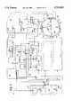
- FIG. 1is a schematic diagram of the microwave tomographic spectroscopy system of the invention.
- FIG. 2is a schematic diagram of the microwave tomographic spectroscopy system of the invention.
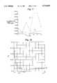
- FIG. 3is a flow diagram of the algorithm for the reverse problem solution.
- FIG. 4is a flow diagram of an alternate reconstruction algorithm for the reverse problem solution.
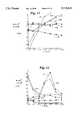
- FIG. 5is a graph of canine cardiac tissue dielectric characteristics as a function of heart cycle.
- FIG. 6is a graph of canine cardiac tissue dielectric characteristics as a function of heart cycle.
- FIG. 7is a graph of canine cardiac tissue dielectric characteristics as a function of occlusion and re-perfusion.
- FIG. 8is a graph of canine cardiac tissue dielectric characteristics as a function of occlusion and re-perfusion.
- FIG. 9is a graph of canine cardiac tissue dielectric characteristics as a function of occlusion and re-perfusion.
- FIG. 10is a graph of canine cardiac tissue dielectric characteristics as a function of occlusion and re-perfusion.
- FIG. 11is a graph of canine cardiac tissue first order and second order dielectric characteristics as a function of time and frequency of microwave emission.
- FIG. 12is a graph of canine cardiac tissue first order and second order dielectric characteristics as a function of time and frequency of microwave emission.
- FIG. 13is a graph of first order canine cardiac tissue dielectric characteristics correlated to frequency of microwave emission.
- FIG. 14is a graph of blood oxygen content correlated to second order canine cardiac tissue dielectric characteristics and frequency of microwave emissions.
- FIG. 15is a graph of blood oxygen contents correlated to first order dielectric correlation coefficients and frequency of microwave emissions.
- FIG. 16is a graph of blood oxygen contents correlated to second order dielectric correlation coefficients and frequency of microwave emissions.
- FIG. 17is a graph of first order and second order dielectric coefficients correlated to total hemoglobin correlation coefficients and frequency of microwave emissions.
- FIG. 18is a graph of second order dielectric characteristics for a human left ventricular myocardium normal tissue to diseased tissue correlated by frequency of microwave emissions.
- FIG. 19is a graph of first order dielectric characteristics for a human left ventricular myocardium normal tissue to diseased tissue correlated by frequency of microwave emissions.
- FIG. 20is an expanded scale graph of the second order dielectric characteristics for a human left ventricular myocardium normal tissue to diseased tissue correlated by frequency of microwave emissions shown in FIG. 18.
- FIG. 21is a flow diagram of an ablation choice algorithm.
- FIGS. 1 and 2are each schematic diagrams of the tomographic spectroscopy system 10 of this invention.
- Utility of this inventionencompasses many fields, however the preferred field described below is that of medical uses. More particularly, the embodiments of the invention claimed below relate to non-invasive diagnosis and therapy for heart arrhythmias.
- the microwave systemenables rapid and highly accurate non-invasive detection and localization of cardiac arrhythmogenic foci, as well as non-invasive cardiac mapping capabilities.
- System 10accomplishes these procedures using a multiple frequency regimen, signal encoding techniques, improved mathematical algorithms, and previously unrecognized correlation functions.
- Identification of the origin of cardiac arrhythmiashas previously depended on one of three principal techniques: catheter mapping, electrical excitation mapping during cardiac surgery, or body surface mapping of electric potentials or magnetic fields.
- catheter mapping and excitation mapping during surgeryare inherently invasive, access limited, and time sensitive.
- Body surface mappingcan be performed in a non-invasive, low risk manner but with such poor definition that the data is generally considered unsuitable for directing therapy.
- the mappingmay be performed using either sequential temporal changes in the electrical potential distribution on the surface of the body or sequential changes in magnetic fields on the body surface.
- the inventiondoes not require insertion of a catheter into a body, nor does it require inserting probes into cardiac tissue.
- reliable and precise (2-5 mm) three dimensional reconstruction of the heart and its electrical excitation sequenceis now possible using this invention.
- Use of the techniques listed below for ablation of arrhythmogenic sitesis non-invasive and advantageously utilizes the different frequencies and directions of energy available so that the ablation threshold will occur only at the designated location.
- the inventiondoes anticipate invasive procedures, for example, ablation systems delivered by catheters or surgical procedures to accomplish physician directed therapy.
- the inventionutilizes novel correlation functions. These functions relate to tissue physical properties and changes of those properties during cell excitation.
- the dielectrical behavior of biological tissuecan be defined by two characteristic parameters: dielectric permeability and conductivity.
- the parameter functionsinclude frequency, temperature, and tissue type.
- the tissue type parameterprovides opportunities for detection of anatomical structure by measuring transmitted, i.e. reflected and scattered, electromagnetic energy through tissue.
- transmittedi.e. reflected and scattered
- the dielectric characteristicscan be readily detected by measuring amplitude and phase of transmitted electromagnetic radiation.
- the problemis more complicated when trying to measure the dielectric values of radiation transmitted through non-homogenous biological tissue simply by using measured amplitude and phase of the transmitted wave. This problem is known as the "inverse” or "reverse” problem and has attracted some attention to its solution.
- This inventionincorporates the strong dependance of tissue characteristics on temperature, and solves the "reverse” problem in novel ways by using multiple frequency and multiple position emitter-receiver configurations.
- system 10comprises microwave emitter-receiver sub-assembly 14 suitable for mounting a plurality of microwave emitters-receivers 16.
- a preferred configuration of emitters-receiversis in a circular array, and each emitter-receiver 16 may be enabled for radial movement relative to the circular array.
- Sub-assembly 14may also comprise a plurality of vertically stacked emitters-receivers.
- a power source 19provides narrow pulse-width electromagnetic energy signals to each emitter of not more than about 10 mW/cm 2 incident power density on an object.
- Power source 19may comprise either a plurality of power sources or a single power source, such as a generator.
- power source 19comprises a sweeping diagnostic generator 22, a diagnostic generator control block 24, an ablation generator 27, and an ablation generator control block 29.
- Sweeping diagnostic generator 22provides multiple frequency low power energy for use in diagnostic applications, while ablation generator 27 provides high power energy for microwave ablation of designated tissue regions. Selection of either of the above generators is accomplished by switch 33 which connects generator output with the emitters 16.
- a channelization mechanism 35is provided for activation and control of channels i, i+1, i+n, for energy emission and reception.
- This subsystemcomprises a channel number switch 36, an amplitude attenuator-detector manipulation (ADM) 39, a phase rotator-detector 42, an amplitude detector 45, a phase detector 48, and an antenna mode switch 53.
- channel number switch 36connects the output of the diagnostic generator 22 with the input of the emitter (or a multiple of emitters) at any particular time.
- the switchconnects all channels with the output of the ablation generator 27.
- Amplitude attenuator-detector 39 and phase rotator-detector 42are in the emitter path of all channels.
- Amplitude attenuator-detector 39attenuates the amplitude of emitted power, and with phase rotator-detector 42 detects and encodes the output signal.
- Amplitude detector 45 and phase detector 48are in the received path of all channels and, in the diagnostic mode, detect and decode the amplitude and phase of the received signal. It is recognized that other coding means, such as polarity, may require additional encoding/de-coding components.
- Antenna mode switch 53functions in all channels to connect the output of the emitter path with the antenna or input path, at the receiver path, with the same antenna.
- Computation and control module means 65includes a central processing unit (CPU) 68, an interface subsystem 72, a display 75 and a display software 77, as well as a memory 82.
- the interface subsystem 72consists of a digital-to-analog converter(s) (DAC) 86, a multiplexer 89, an analog-to-digital converter (ADC) 92, and a control block 94 which creates time synchronization of controlled processes and receives data to be analyzed.
- DACdigital-to-analog converter
- ADCanalog-to-digital converter
- An auxiliaries subsystem 102comprises a thermostatic shield 105 for controlling the temperature of an interface medium 106, for example, a fluid such as a solution of titanium and barium having a preliminary dielectrically adjustable dielectric permittivity between about 50 and 90 at 2.45 GHz and a dielectric loss between about 5 and 25, between the emitters-receivers 16, a thermostatic control block 108 for controlling thermostatic shield 105, and a basic channel control block 111 for control of the received signal from the Bi control channels when the system 10 is in a calibration mode. Additional auxiliary components may be added depending on desired performance features of the system, for example, an electrocardiogram analyzer and/or a printer 119 may be useful to the system 10.
- a fluidsuch as a solution of titanium and barium having a preliminary dielectrically adjustable dielectric permittivity between about 50 and 90 at 2.45 GHz and a dielectric loss between about 5 and 25, between the emitters-receivers 16, a thermostatic control block 108 for controlling thermostatic shield 105, and a basic channel
- target tissue 135is irradiated in sequence with low energy microwave radiation from the first to the n th emitter (receiver) 16, while simultaneously taking measurement of the received signals in (emitter) receivers 16 which in that particular step of the sequence are not functioning as an emitter.
- emitter-receivers 16are used to receive signals emitted by a single emitter-receiver 16 in any given instance of time.
- the system 10rapidly changes channel number and antenna mode in sequence according to the above configuration. After one cycle of n-channel emissions and receptions, sweeping diagnostic generator 22 provides another cycle of n-channel switched measurements.
- the total quantity of cycle measurementsis normally not more than N ⁇ M, where N is the quantity of antennas, and M is the quantity of used diagnostic frequencies. It is also recognized that simultaneous measurements may be obtained using a multiple encoded frequency configuration. Following the measurements, system 10 solves the "reverse" problem according to the received information and the novel algorithms described more fully below in relation to FIGS. 3 and 4. When measuring physiologic changes it is important to understand the time it takes for a physiologic event to occur, for example a myocardial contraction. These time periods are defined as tissue event time cycles.
- Data acquisition in system 10is performed in time intervals which are a fraction of a tissue event time cycle so that data acquisition may occur many times during each tissue event and are stored in memory 82. Reconstruction time is fast enough that body motion is not a problem.
- Anatomical object structure and temperature profilesare observable on display 75, may be manipulated using routines of display software 77, and may be printed using printer 119.
- the arrhythmogenic zones of the heartare defined as those regions with particular .di-elect cons.' and .di-elect cons.” values. Spatial coordinates of these zones are defined with the help of the display software, the CPU, and the memory.
- system 10periodically makes temperature control corrections of the interface medium 106 with the aide of the thermostatic control block 108.
- System 10also synchronizes with the heart cycle in which the tissue is resident using electrocardiogram analyzer 115.
- a key feature of system 10 which facilitates the speed and accuracy of calculationis the use of a coding device for encoding the microwave signals supplied to the emitters.
- a coding devicefor encoding the microwave signals supplied to the emitters.
- the signalsare distinguishable by their originating emitter or emitter group.
- Preferred encoding techniquesare phase, amplitude, or polarity modulation; however it is also within the scope of the invention to employ frequency modulation. Frequency modulation may be useful in certain applications where simultaneous emissions from a plurality of emitters are required.
- System 10is one embodiment for using the novel method steps of this invention which permits non-invasive microwave tomographic spectroscopy of tissue.
- the methodcomprises the steps of: providing a microwave radiation power source; providing a plurality of microwave radiation emitter-receivers; and controlling the plurality of microwave radiation emitter-receivers so that a plurality of emitter-receivers are able to emit multiple microwave frequency radiation from the power source to a plurality of emitter-receivers that are receiving the microwave radiation.
- Further stepsinclude: placing an interface medium between the emitting and receiving microwave emitter-receivers for dielectric matching; placing tissue to be irradiated within the interface medium; emitting the microwave radiation from the microwave emitter-receivers; receiving the microwave radiation in the microwave emitter-receivers after interacting with the tissue; and measuring a change in the microwave radiation after interacting with the tissue.
- the measuring step of the above methodincorporates both old and new concepts to refine and render useful the data derived from this form of electromagnetic imaging.
- the measuring stepscomprise computations using an input data formation component 220, a direct problem solution component 222, a reverse problem solution component 224, a multiple frequency correlation component 226, a computer visualization control 236, and a tomographic spectroscopic image 238.
- the direct problem solutionis a known calculation which solves microwave propagation from emitter to receiver through a biological means.
- Solution of the reverse problemallows precise computation and generation of a tomographic spectroscopically useful image of the tissue based on the measured change of the microwave radiation.
- the reverse problem solution stepscomprise: determination of a functional formation component 228 which sums the input from all emitters-receivers; using a gradient formation component 230 as a derivative of the functional formation component to simplify processing speed; calculating a minimization parameter tau to verify the accuracy of the gradient function and to reconstruct in the most accurate manner; and performing an E* calculation 234.
- the E* calculation 234uses the following:
- .di-elect cons.'said .di-elect cons.” are the values of dielectric permittivity and loss measured by the invention and i represents the imaginary number.
- .di-elect cons.*as a representative value of .di-elect cons.' and .di-elect cons.” is a convenient mathematical tool. It should be understood that the invention may also use either .di-elect cons.' and/or .di-elect cons.” as the measured dielectric parameter for generating an image.
- .di-elect cons.*The reason for using .di-elect cons.* is that dielectric contrast between tissue and/or tissue physiologic states may be found in either a difference or change in .di-elect cons.' and/or .di-elect cons.”. If .di-elect cons.' and .di-elect cons.” are calculated together as .di-elect cons.* then any dielectric change in either .di-elect cons.' or .di-elect cons.” will be detected in an .di-elect cons.* calculation. As will be seen later, some physiological dielectric changes are best evaluated by using only .di-elect cons.' or .di-elect cons.”. It is important to recognize that wherever .di-elect cons.* is used, .di-elect cons.' or .di-elect cons.” can also be used in place of .di-elect cons.*.
- the flow chart depicted in FIG. 4represents an embodiment of the present invention for use in a catheter delivered microwave tomographic system.
- Datais fed into a direct problem solution step 240 from a working arrays formation step 242 and an antenna simulation step 244.
- the working arrays formation step 242receives data from a frequency and temperature correlation step 248 which derived its initial values from a zero approximation step 250.
- the antenna simulation step 244provides values for starting the calculation process acting as a base line from which to construct an image.
- Direct problem solution step 240then is able to solve an image problem based on knowing what the amplitude and phase of the emitted microwave energy is and making an assumption as to what the biological tissue dielectric effects will be and calculating an expected amplitude and phase value for the transmitted microwave energy.
- This solution from the direct problem solution step 240is then passed to reverse problem solution step 252 comprising an equation system formation step 254, a Jacobian formation step 256, and a matrix irreversing step 258.
- the reverse problem solution step 252then calculates an image of the biological tissue based on known emitted microwave amplitude and phase values and known received amplitude and phase values from the emitter receiver arrays.
- the reverse problem solutionis generating the tomographic image by knowing the amplitude and phase of the emitted microwave energy and the amplitude and phase of the transmitted or received microwave energy in order to calculate the dielectric characteristics of the biological tissue through which the microwave energy has passed.
- This image data from the matrix irreversing step 258is then passed through an error correcting iteration process involving an error estimation step 260 and a first error correction step 262.
- the matrix irreversing step 258 in conjunction with error estimation 260 and first error correction 262forms an iterative loop that begins with inputing the first grid point .di-elect cons.* ⁇ T into the error estimation step 260.
- a .di-elect cons.* j+1 , T j+1is generated in which j is the grid number in the coordinate system for generating the two or three dimensional image construct and where j is equal to values from 1-n.
- T valueAfter each .di-elect cons.*, T value has undergone an error estimation and first error correction, the value is then passed to an anatomical and T reconstruction and anatomy error estimation step 264. At this point the value as fed into error estimation step 264 is compared with the .di-elect cons.” value and if the error estimation has occurred the value is passed onto an anatomical structure and T visualization step 266 which serves the purpose of generating the two dimensional or three dimensional image of the biological tissue based on dielectric contrast. If, however, the error estimation step results in a no response, a data point is passed to a second error correction step 268 which then adjusts, in conjunction with the first correction step 262, the values generated by frequency and temperature correlation step 248.
- FIG. 5is a graph demonstrating the capability of system 10 to detect cardiac excitation by changes in dielectric characteristics of cardiac tissue.
- FIG. 5shows the change in .di-elect cons.' values at the onset and throughout the period ⁇ T 1 of an electrical excitation process and during the transition period ⁇ T 2 to recovery.
- FIG. 6discloses similar detection capabilities for system 10, but for values of the .di-elect cons.” dielectric parameter. In both FIGS. 5 and 6, each point represents a mean value for seven measurements.
- FIGS. 7-10are graphs demonstrating the percent change of a selected dielectric characteristic, for multiple frequencies, during a series of coronary arterial occlusions.
- FIGS. 7 and 8disclose, over a long duration, a series of short occlusions followed by a long occlusion. These figures demonstrate the correlation of dielectric characteristics for .di-elect cons.' and .di-elect cons.” depending on the degree of cardiac ischemia. This pattern of dielectric changes conforms with the known tissue phenomenon of a protective effect from pre-conditioning prior to a total occlusion.
- FIGS. 9 and 10disclose, over a short duration, a series of short occlusions followed by a long occlusion. These figures support the conclusions stated above in relation to FIGS. 7 and 8.
- FIG. 10provides further example of the value of multiple frequency or spectroscopic analysis of tissue.
- the curve of the values of percent change of .di-elect cons.” at 4.1 GHzis relatively flat and less useful as compared to the corresponding values at either 0.2 GHz or 1.17 GHz. This highlights the need for system 10 to detect tissue excitation phenomena and other physiological events, e.g. ischemia, using multiple frequency techniques which might otherwise remain undetected or not useful in a single frequency analysis. This is further demonstrated in the .di-elect cons.*(f) graphs of FIGS.
- curves 145, 147, 149, 151, 153, and 155represent time after occlusion (i.e., acute ischemia) of 0, 15, 30, 45, 120, and 125 minutes respectively for .di-elect cons.' (shown by * curves) and .di-elect cons.” (shown by o curves).
- the value of ⁇is ⁇ .di-elect cons.*/.di-elect cons.* before.
- Reperfusionoccurs at time 125 minutes, and is represented by curves 155.
- FIGS. 13 and 14disclose the correlation of dielectric characteristics to blood oxyhemoglobin content.
- the dielectric characteristicis the percent of (.di-elect cons.'(HbO 2 )-.di-elect cons.'(86.9))/.di-elect cons.'(86.9)
- the dielectric characteristicis the percent of (.di-elect cons.”(HbO 2 )-.di-elect cons.”(86.9))/.di-elect cons.”(86.9).
- the frequency curves 161, 163, 165, 167, 169, 171, and 173correspond to 0.2 GHz, 1.14 GHz, 2.13 GHz, 3.12 GHz, 4.01 GHz, 5.0 GHz, and 6.0 GHz, respectively.
- the dielectric permittivity of oxyhemoglobin (HbO 2 ), the partial pressure of oxygen (PO 2 ) and total hemoglobin (tHb) contentare correlated to microwave frequency range 0.2-6 MHz in FIG. 15.
- the highest degree of correlation for oxyhemoglobinoccurs between the frequency range 0.5-2.5 MHz. Through this range the dielectric permittivity value .di-elect cons.' is most sensitive to the oxyhemoglobin saturation content of blood.
- the correlation coefficient curve for .di-elect cons.”, dielectric loss,is disclosed in FIG. 16.
- the correlation coefficient for HbO 2is highest at approximately 2 GHz with the correlation coefficient for PO 2 approaching unity between 2.5 and 4 GHz.
- FIGS. 15 and 16The correlation coefficient studies disclosed in FIGS. 15 and 16 are representative of the invention's ability to distinguish between oxyhemoglobin (HbO 2 ) saturation percentage and PO 2 . Both of these values are important pieces of information useful to health care providers.
- oxyhemoglobin (HbO 2 ) saturation percentageand PO 2 . Both of these values are important pieces of information useful to health care providers.
- oximeterreal time bed side photometric means for determining oxyhemoglobin saturation percentage
- arterial bloodmust be withdrawn from a patient into specialized syringes and put through a machine capable of directly measuring the partial pressure of gases in a liquid.
- the .di-elect cons.' and .di-elect cons.” curves for total hemoglobin as a reference correlationare depicted in FIG. 17.
- the .di-elect cons.' curve as shownis a fairly flat correlation curve that is fairly non-correlative, maintaining values of correlation less than -0.995 throughout most of the curve.
- the .di-elect cons.” curveshows an increase in correlation to total hemoglobin for the microwave frequency range between 4 and 5 GHz.
- correlation values for oxyhemoglobin PO 2 and total hemoglobinmay accurately derive from these correlation curves during a single frequency range scan from 0.2-6 GHz and calculating the dielectric permittivity .di-elect cons.' and dielectric loss .di-elect cons.” values for blood.
- the concentration of oxyhemoglobin saturationwould then be best correlated with the .di-elect cons.' value at, or about, 1.5 GHz
- the PO 2 valuewould then be calculated from the correlation value of the dielectric loss, .di-elect cons.”, calculated at, or about, 3.5 GHz
- tHbcould be calculated from the correlation value of the dielectric loss curve, .di-elect cons.”, calculated at, or about, 4.5 GHz.
- Each scan through the frequency range from 0.2-6 GHzwould require no more than several milliseconds of microwave exposure and then computing the value calculations.
- the present inventioncould feasibly be used at the bedside for virtual real time assessment of these parameters.
- the present inventionis able to provide a real time bedside monitoring of HbO 2 saturation percentage and PO 2 values.
- the present inventiondoes so without necessitating removal of blood from the patient and the delay and cost of sending the blood to the laboratory for analysis.
- This inventionis not limited to HbO 2 and PO 2 values. Any blood and tissue component possessing a dielectric contrast characteristic is capable of direct measurement and real time evaluation, non-invasively, using this invention.
- the present inventionalso possesses an ability to detect dielectric characteristic changes that occur in a tissue that is becoming diseased.
- a tissue that is becoming diseasedBy way of example, a weakened diseased aneurysmal portion of a ten year old male's left ventricle was repaired. During this repair the diseased portion was resected from the heart such that the diseased portion was removed entirely. This requires that the resection margins contain normal myocardium.
- the inventionwas used to evaluate this piece of resected heart tissue and the test results are presented in FIGS. 18-20.
- the .di-elect cons.” dielectric loss characteristic of normal myocardiumis shown in FIG. 18 as a curve 200 measured over a microwave frequency range between 0.2 and 6 GHz. Throughout the entire frequency range this normal tissue is distinguishable from the abnormal tissue as shown by curve 202.
- FIG. 19shows the .di-elect cons.' dielectric permittivity characteristic curves for this same tissue sample.
- Normal tissuehas a .di-elect cons.' single curve represented by curve 204.
- the abnormal tissueis shown in curve 206.
- the normal myocardial tissueis distinguishable from abnormal myocardial tissue over the entire microwave frequency range used in the present invention.
- FIG. 20is an expanded scale graphic representation of the same .di-elect cons.” dielectric loss data of FIG. 18.
- Curve 208represents the .di-elect cons.” for normal myocardial tissue with curve 210 representing the .di-elect cons.” values for abnormal cardiac tissue.
- the present inventionis able to use this dielectric characteristic difference to generate an image.
- an anatomical image of the organsis obtained based on the dielectric characteristic differences between the various tissues as demonstrated in FIGS. 5-12 and 18-20.
- the inventionfacilitate anatomical location of diseased abnormal tissue within normal tissue. This anatomical information is useful in many ways. An example of one important use would be to direct real time therapy. Often abnormal myocardial tissue causes deleterious rhythm disturbances. Unfortunately, this abnormal tissue may be visually indistinguishable from surrounding normal myocardium.
- the present inventionprovides real time imaging of the abnormal tissue based on the dielectric characteristic differences such as those detected in FIGS. 18-20.
- a clinicianuses fast reconstruction routines and scanning through the frequency range in at time rates that are fractions of the tissue event time cycle to create a map of the abnormal tissue.
- the investigatormay reconstruct the dielectric properties to generate a functional excitation map through the abnormal tissue area or alternatively may reconstruct a temporal change map and correlate those temporal changes to known electrical markers for anomalies within the tissue.
- the clinicianmay then direct ablation therapy to remove this abnormal rhythm focus and evaluate the adequacy of the tissue removal.
- FIG. 21An embodiment of the present invention using laser or microwave sources of ablation is disclosed in FIG. 21.
- a method for ablation of a lesionfor example, an arrhythmogenic focus within normal myocardial tissue, is performed beginning with inputing information into an input data formation step 300 from anatomical structure analysis derived from data generated by the invention disclosed in FIG. 2 and expected temperature distribution values.
- the input data formation stepuses information from a microwave power source as an approximation step 302 or a laser power source as an approximation step 304 to derive input to be fed to a direct problem solution for microwave 306 or direct problem solution for laser control 308.
- a determination step for determining the possible available microwave and laser power sourcesis undertaken at step 310.
- the result of this determinationis passed onto a sources and lesions correlation databank 312 to derive an approximation step 314, also taking input from an antenna simulation step 316.
- the current expected temperatureis calculated at step 318 and corrected for a temperature non-linearity at step 320.
- the results of the direct problem solutions for microwave or laser 306, 308 in conjunction with the corrected current temperature from 320is incorporated into a biological heat equation solution 322 to derive an actual temperature solution.
- Temperature distribution from the bioequation step 322is passed to a lesion localization step 324 which provides data back to the source lesion correlation databank 312 for running the next approximation through to the input data formation 300 for the next determination of the bioheat equation solution step 322.
- Information from the equation solution step 322is also passed to a different necessary lesion current lesion formation step for comparing the current lesion size with the estimated necessary lesion size to determine if optimum therapy has been achieved or not. If treatment has been achieved, the decision then passes to optimal region step 328. If the current lesion is different than the necessary lesion, the different information is passed back to step sources lesion correlation databank 312 for a reapproximation at step 314 on through input data formation 300 to undertake the next treatment in order to more closely approximate the necessary lesion through treatment.
- the number of steps through the iterative processare monitored by switch 330 with comparison of an expected location size of lesion step 332 at step 0, step 334. For steps greater than 0, switch 330 switches to step greater than zero step 336. The entire process is continuously re-evaluated for completeness of ablation therapy and re-evaluating on a real time basis the lesion generated by analysis of the anatomical structure derived from the microwave tomographic imaging system.
- the inventionprovides for using microwave energy in a novel approach providing rapid real time assessment of biological function and anatomical structure by reverse problem solution for the dielectric characteristics of biological tissues.
- the inventionachieves substantial increase in processing speed as well as substantial improvement in resolving power over any known prior art.
- the present inventionalso provides for techniques in evaluating real time parameters for determining biological component concentrations or physiologic characteristics based on the dielectric contrast between different states of physiologic activity for the biological compound or physiologic reaction.
Landscapes
- Health & Medical Sciences (AREA)
- Life Sciences & Earth Sciences (AREA)
- Surgery (AREA)
- Physics & Mathematics (AREA)
- General Health & Medical Sciences (AREA)
- Engineering & Computer Science (AREA)
- Medical Informatics (AREA)
- Heart & Thoracic Surgery (AREA)
- Molecular Biology (AREA)
- Animal Behavior & Ethology (AREA)
- Biomedical Technology (AREA)
- Public Health (AREA)
- Veterinary Medicine (AREA)
- Nuclear Medicine, Radiotherapy & Molecular Imaging (AREA)
- Pathology (AREA)
- Otolaryngology (AREA)
- Electromagnetism (AREA)
- Radiology & Medical Imaging (AREA)
- Biophysics (AREA)
- Chemical & Material Sciences (AREA)
- Analytical Chemistry (AREA)
- Biochemistry (AREA)
- General Physics & Mathematics (AREA)
- Immunology (AREA)
- Plasma & Fusion (AREA)
- Optics & Photonics (AREA)
- Surgical Instruments (AREA)
- Measurement And Recording Of Electrical Phenomena And Electrical Characteristics Of The Living Body (AREA)
- Measurement Of The Respiration, Hearing Ability, Form, And Blood Characteristics Of Living Organisms (AREA)
Abstract
Description
.di-elect cons.'=.di-elect cons./.di-elect cons..sub.0.Equation 1
.di-elect cons.*=.di-elect cons.'+i.di-elect cons."Equation 3
Claims (36)
Priority Applications (9)
| Application Number | Priority Date | Filing Date | Title |
|---|---|---|---|
| US08/250,762US5715819A (en) | 1994-05-26 | 1994-05-26 | Microwave tomographic spectroscopy system and method |
| PCT/US1995/006507WO1995032665A1 (en) | 1994-05-26 | 1995-05-24 | Microwave tomographic spectroscopy system and method |
| JP8500996AJPH10504893A (en) | 1994-05-26 | 1995-05-24 | Microwave tomography spectroscopy system and method |
| CN95193883ACN1123320C (en) | 1994-05-26 | 1995-05-24 | Microwave tomography spectrum system and method |
| AU27618/95AAU2761895A (en) | 1994-05-26 | 1995-05-24 | Microwave tomographic spectroscopy system and method |
| CA002191312ACA2191312A1 (en) | 1994-05-26 | 1995-05-24 | Microwave tomographic spectroscopy system and method |
| EP95922880AEP0762847A4 (en) | 1994-05-26 | 1995-05-24 | Microwave tomographic spectroscopy system and method |
| RU96124805/14ARU2238033C2 (en) | 1994-05-26 | 1995-05-24 | Method and microwave tomograph device for carrying out spectroscopy examination |
| KR1019960706696AKR970703111A (en) | 1994-05-26 | 1996-11-26 | MICROWAVE TOMOGRAPHIC SPECTROSCOPY SYSTEM AND METHOD |
Applications Claiming Priority (1)
| Application Number | Priority Date | Filing Date | Title |
|---|---|---|---|
| US08/250,762US5715819A (en) | 1994-05-26 | 1994-05-26 | Microwave tomographic spectroscopy system and method |
Publications (1)
| Publication Number | Publication Date |
|---|---|
| US5715819Atrue US5715819A (en) | 1998-02-10 |
Family
ID=22949038
Family Applications (1)
| Application Number | Title | Priority Date | Filing Date |
|---|---|---|---|
| US08/250,762Expired - LifetimeUS5715819A (en) | 1994-05-26 | 1994-05-26 | Microwave tomographic spectroscopy system and method |
Country Status (9)
| Country | Link |
|---|---|
| US (1) | US5715819A (en) |
| EP (1) | EP0762847A4 (en) |
| JP (1) | JPH10504893A (en) |
| KR (1) | KR970703111A (en) |
| CN (1) | CN1123320C (en) |
| AU (1) | AU2761895A (en) |
| CA (1) | CA2191312A1 (en) |
| RU (1) | RU2238033C2 (en) |
| WO (1) | WO1995032665A1 (en) |
Cited By (171)
| Publication number | Priority date | Publication date | Assignee | Title |
|---|---|---|---|---|
| WO1998052464A1 (en) | 1997-05-23 | 1998-11-26 | The Carolinas Heart Institute | Electromagnetical imaging and therapeutic (emit) systems |
| US6026173A (en)* | 1997-07-05 | 2000-02-15 | Svenson; Robert H. | Electromagnetic imaging and therapeutic (EMIT) systems |
| US6084415A (en)* | 1993-02-03 | 2000-07-04 | Baaaath; Lars B. | Method for measuring molecular composition or molecular densities in gases |
| WO2000047283A3 (en)* | 1999-02-09 | 2000-12-14 | Kai Tech Inc | Microwave systems for medical hyperthermia, thermotherapy and diagnosis |
| WO2001012261A1 (en)* | 1999-08-19 | 2001-02-22 | Kai Technologies, Inc. | Microwave devices for medical hyperthermia, thermotherapy and diagnosis |
| US6233490B1 (en) | 1999-02-09 | 2001-05-15 | Kai Technologies, Inc. | Microwave antennas for medical hyperthermia, thermotherapy and diagnosis |
| WO2002018920A1 (en)* | 2000-08-31 | 2002-03-07 | Aktiebolaget October Biometrics | Device, method and system for measuring the distribution of selected properties in a material |
| US20020075019A1 (en)* | 2000-12-04 | 2002-06-20 | Leonard Hayden | Wafer probe |
| US20030184404A1 (en)* | 2002-03-28 | 2003-10-02 | Mike Andrews | Waveguide adapter |
| DE10226845A1 (en)* | 2002-06-16 | 2004-01-08 | Otto-Von-Guericke-Universität Magdeburg | Complex permittivity measurement unit uses multiple cavity resonances |
| US20040030238A1 (en)* | 2002-05-17 | 2004-02-12 | Mr Instruments, Inc. | Cavity resonator for MR systems |
| US20040077943A1 (en)* | 2002-04-05 | 2004-04-22 | Meaney Paul M. | Systems and methods for 3-D data acquisition for microwave imaging |
| US20040104268A1 (en)* | 2002-07-30 | 2004-06-03 | Bailey Kenneth Stephen | Plug in credit card reader module for wireless cellular phone verifications |
| US20040232935A1 (en)* | 2003-05-23 | 2004-11-25 | Craig Stewart | Chuck for holding a device under test |
| US20050035777A1 (en)* | 1997-05-28 | 2005-02-17 | Randy Schwindt | Probe holder for testing of a test device |
| US6876878B2 (en)* | 1996-06-26 | 2005-04-05 | University Of Utah Research Foundation | Medical broad band electromagnetic holographic imaging |
| US20050156610A1 (en)* | 2002-01-25 | 2005-07-21 | Peter Navratil | Probe station |
| US20050179427A1 (en)* | 2000-09-05 | 2005-08-18 | Cascade Microtech, Inc. | Probe station |
| US20050184744A1 (en)* | 1992-06-11 | 2005-08-25 | Cascademicrotech, Inc. | Wafer probe station having a skirting component |
| US20050203387A1 (en)* | 2002-04-05 | 2005-09-15 | Microwave Imaging Systems Technologies, Inc. | Non-invasive microwave analysis systems |
| US20050264303A1 (en)* | 2004-02-12 | 2005-12-01 | Bailey Kenneth S | Radiation monitoring of body part sizing and use of such sizing for person monitoring |
| US20060008226A1 (en)* | 2001-05-04 | 2006-01-12 | Cascade Microtech, Inc. | Fiber optic wafer probe |
| US20060028200A1 (en)* | 2000-09-05 | 2006-02-09 | Cascade Microtech, Inc. | Chuck for holding a device under test |
| US20060104489A1 (en)* | 2004-08-23 | 2006-05-18 | Bailey Kenneth S | Minutia detection from measurement of a human skull and identifying and profiling individuals from the human skull detection |
| US20060110010A1 (en)* | 1999-12-30 | 2006-05-25 | Bailey Kenneth S | Human body: scanning, typing and profiling system |
| US20060132157A1 (en)* | 1992-06-11 | 2006-06-22 | Cascade Microtech, Inc. | Wafer probe station having environment control enclosure |
| US20060169897A1 (en)* | 2005-01-31 | 2006-08-03 | Cascade Microtech, Inc. | Microscope system for testing semiconductors |
| US20060184041A1 (en)* | 2005-01-31 | 2006-08-17 | Cascade Microtech, Inc. | System for testing semiconductors |
| US20060241410A1 (en)* | 2003-04-04 | 2006-10-26 | Qianqian Fang | Microwave imaging system and processes, and associated software products |
| US20060279299A1 (en)* | 2005-06-08 | 2006-12-14 | Cascade Microtech Inc. | High frequency probe |
| WO2005122061A3 (en)* | 2004-02-12 | 2006-12-21 | Celunet Inc | Radiation monitoring of body part sizing and use of such sizing for person monitoring |
| US20060290357A1 (en)* | 2005-06-13 | 2006-12-28 | Richard Campbell | Wideband active-passive differential signal probe |
| US7161363B2 (en) | 2002-05-23 | 2007-01-09 | Cascade Microtech, Inc. | Probe for testing a device under test |
| US20070015993A1 (en)* | 2005-07-13 | 2007-01-18 | Clemson University | Microwave imaging assisted ultrasonically |
| US20070075724A1 (en)* | 2004-06-07 | 2007-04-05 | Cascade Microtech, Inc. | Thermal optical chuck |
| US20070109001A1 (en)* | 1995-04-14 | 2007-05-17 | Cascade Microtech, Inc. | System for evaluating probing networks |
| US7239731B1 (en)* | 2002-11-26 | 2007-07-03 | Emimaging Ltd | System and method for non-destructive functional imaging and mapping of electrical excitation of biological tissues using electromagnetic field tomography and spectroscopy |
| US20070194778A1 (en)* | 2002-12-13 | 2007-08-23 | Cascade Microtech, Inc. | Guarded tub enclosure |
| US20070205784A1 (en)* | 2003-05-06 | 2007-09-06 | Cascade Microtech, Inc. | Switched suspended conductor and connection |
| US7271603B2 (en) | 2003-05-23 | 2007-09-18 | Cascade Microtech, Inc. | Shielded probe for testing a device under test |
| US7285969B2 (en) | 2002-11-13 | 2007-10-23 | Cascade Microtech, Inc. | Probe for combined signals |
| US20070245536A1 (en)* | 1998-07-14 | 2007-10-25 | Cascade Microtech,, Inc. | Membrane probing system |
| US20070265523A1 (en)* | 2006-05-11 | 2007-11-15 | Sten Pahlsson | Method and system for determining process parameters |
| US20070285085A1 (en)* | 2006-06-12 | 2007-12-13 | Cascade Microtech, Inc. | Differential signal probing system |
| US20070285111A1 (en)* | 2006-06-12 | 2007-12-13 | Cascade Microtech, Inc. | Test structure and probe for differential signals |
| US20080012578A1 (en)* | 2006-07-14 | 2008-01-17 | Cascade Microtech, Inc. | System for detecting molecular structure and events |
| US20080024133A1 (en)* | 2005-11-25 | 2008-01-31 | Mr Instruments, Inc. | Cavity resonator for magnetic resonance systems |
| US7330041B2 (en) | 2004-06-14 | 2008-02-12 | Cascade Microtech, Inc. | Localizing a temperature of a device for testing |
| US20080048693A1 (en)* | 1997-06-06 | 2008-02-28 | Cascade Microtech, Inc. | Probe station having multiple enclosures |
| US20080054922A1 (en)* | 2002-11-08 | 2008-03-06 | Cascade Microtech, Inc. | Probe station with low noise characteristics |
| US7355420B2 (en) | 2001-08-21 | 2008-04-08 | Cascade Microtech, Inc. | Membrane probing system |
| US7362115B2 (en) | 2003-12-24 | 2008-04-22 | Cascade Microtech, Inc. | Chuck with integrated wafer support |
| US7368927B2 (en) | 2004-07-07 | 2008-05-06 | Cascade Microtech, Inc. | Probe head having a membrane suspended probe |
| US20080171949A1 (en)* | 2007-01-17 | 2008-07-17 | The University Hospital Of North Staffordshire Nhs Trust | Intraoperative electromagnetic apparatus and related technology |
| US7403025B2 (en) | 2000-02-25 | 2008-07-22 | Cascade Microtech, Inc. | Membrane probing system |
| US7420381B2 (en) | 2004-09-13 | 2008-09-02 | Cascade Microtech, Inc. | Double sided probing structures |
| US20080218187A1 (en)* | 2003-10-22 | 2008-09-11 | Cascade Microtech, Inc. | Probe testing structure |
| US7427868B2 (en) | 2003-12-24 | 2008-09-23 | Cascade Microtech, Inc. | Active wafer probe |
| US7443186B2 (en) | 2006-06-12 | 2008-10-28 | Cascade Microtech, Inc. | On-wafer test structures for differential signals |
| US7498828B2 (en) | 2002-11-25 | 2009-03-03 | Cascade Microtech, Inc. | Probe station with low inductance path |
| US20090119040A1 (en)* | 1997-06-26 | 2009-05-07 | Zhdanov Michael S | Security screening and inspection based on broadband electromagnetic holographic imaging |
| US7533462B2 (en) | 1999-06-04 | 2009-05-19 | Cascade Microtech, Inc. | Method of constructing a membrane probe |
| US7535247B2 (en) | 2005-01-31 | 2009-05-19 | Cascade Microtech, Inc. | Interface for testing semiconductors |
| US7541821B2 (en) | 1996-08-08 | 2009-06-02 | Cascade Microtech, Inc. | Membrane probing system with local contact scrub |
| US7609077B2 (en) | 2006-06-09 | 2009-10-27 | Cascade Microtech, Inc. | Differential signal probe with integral balun |
| US7616017B2 (en) | 1999-06-30 | 2009-11-10 | Cascade Microtech, Inc. | Probe station thermal chuck with shielding for capacitive current |
| US20100005891A1 (en)* | 2006-09-25 | 2010-01-14 | Ste D'applications Technologies De L'imagerie Micro-Onde | Microwave device for controlling material |
| US20100085069A1 (en)* | 2008-10-06 | 2010-04-08 | Smith Kenneth R | Impedance optimized interface for membrane probe application |
| US20100117652A1 (en)* | 2008-11-12 | 2010-05-13 | Peter Cork | Bore tube assembly |
| US7723999B2 (en) | 2006-06-12 | 2010-05-25 | Cascade Microtech, Inc. | Calibration structures for differential signal probing |
| US20100127725A1 (en)* | 2008-11-21 | 2010-05-27 | Smith Kenneth R | Replaceable coupon for a probing apparatus |
| US7876114B2 (en) | 2007-08-08 | 2011-01-25 | Cascade Microtech, Inc. | Differential waveguide probe |
| WO2011027127A2 (en) | 2009-09-04 | 2011-03-10 | Keele University | Electromagnetic tomography apparatuses and methods |
| US20110227586A1 (en)* | 2010-03-19 | 2011-09-22 | University Of Manitoba | Microwave tomography systems and methods |
| EP2404550A1 (en) | 2010-07-08 | 2012-01-11 | EMImaging Limited | Systems and methods of 4D electromagnetic tomographic (EMT) differential (dynamic) fused imaging |
| CN102397056A (en)* | 2010-09-07 | 2012-04-04 | 华东师范大学 | Method for performing microwave near-field tumor imaging detection by using radial iteration algorithm |
| US8319503B2 (en) | 2008-11-24 | 2012-11-27 | Cascade Microtech, Inc. | Test apparatus for measuring a characteristic of a device under test |
| US8717430B2 (en) | 2010-04-26 | 2014-05-06 | Medtronic Navigation, Inc. | System and method for radio-frequency imaging, registration, and localization |
| US8880185B2 (en) | 2010-06-11 | 2014-11-04 | Boston Scientific Scimed, Inc. | Renal denervation and stimulation employing wireless vascular energy transfer arrangement |
| US8939970B2 (en) | 2004-09-10 | 2015-01-27 | Vessix Vascular, Inc. | Tuned RF energy and electrical tissue characterization for selective treatment of target tissues |
| US8951251B2 (en) | 2011-11-08 | 2015-02-10 | Boston Scientific Scimed, Inc. | Ostial renal nerve ablation |
| WO2015024020A1 (en)* | 2013-08-16 | 2015-02-19 | The General Hospital Corporation | Portable diffraction-based imaging and diagnostic systems and methods |
| US8974451B2 (en) | 2010-10-25 | 2015-03-10 | Boston Scientific Scimed, Inc. | Renal nerve ablation using conductive fluid jet and RF energy |
| US9023034B2 (en) | 2010-11-22 | 2015-05-05 | Boston Scientific Scimed, Inc. | Renal ablation electrode with force-activatable conduction apparatus |
| US9028485B2 (en) | 2010-11-15 | 2015-05-12 | Boston Scientific Scimed, Inc. | Self-expanding cooling electrode for renal nerve ablation |
| US9028472B2 (en) | 2011-12-23 | 2015-05-12 | Vessix Vascular, Inc. | Methods and apparatuses for remodeling tissue of or adjacent to a body passage |
| US9050106B2 (en) | 2011-12-29 | 2015-06-09 | Boston Scientific Scimed, Inc. | Off-wall electrode device and methods for nerve modulation |
| US9060761B2 (en) | 2010-11-18 | 2015-06-23 | Boston Scientific Scime, Inc. | Catheter-focused magnetic field induced renal nerve ablation |
| US9072449B2 (en) | 2013-03-15 | 2015-07-07 | Emtensor Gmbh | Wearable/man-portable electromagnetic tomographic imaging |
| WO2015101921A1 (en)* | 2013-12-30 | 2015-07-09 | University Of Manitoba | Imaging using gated elements |
| US9079000B2 (en) | 2011-10-18 | 2015-07-14 | Boston Scientific Scimed, Inc. | Integrated crossing balloon catheter |
| US9084609B2 (en) | 2010-07-30 | 2015-07-21 | Boston Scientific Scime, Inc. | Spiral balloon catheter for renal nerve ablation |
| US9089350B2 (en) | 2010-11-16 | 2015-07-28 | Boston Scientific Scimed, Inc. | Renal denervation catheter with RF electrode and integral contrast dye injection arrangement |
| US9119632B2 (en) | 2011-11-21 | 2015-09-01 | Boston Scientific Scimed, Inc. | Deflectable renal nerve ablation catheter |
| US9119600B2 (en) | 2011-11-15 | 2015-09-01 | Boston Scientific Scimed, Inc. | Device and methods for renal nerve modulation monitoring |
| US9125667B2 (en) | 2004-09-10 | 2015-09-08 | Vessix Vascular, Inc. | System for inducing desirable temperature effects on body tissue |
| US9125666B2 (en) | 2003-09-12 | 2015-09-08 | Vessix Vascular, Inc. | Selectable eccentric remodeling and/or ablation of atherosclerotic material |
| US9155589B2 (en) | 2010-07-30 | 2015-10-13 | Boston Scientific Scimed, Inc. | Sequential activation RF electrode set for renal nerve ablation |
| US9162046B2 (en) | 2011-10-18 | 2015-10-20 | Boston Scientific Scimed, Inc. | Deflectable medical devices |
| US9173696B2 (en) | 2012-09-17 | 2015-11-03 | Boston Scientific Scimed, Inc. | Self-positioning electrode system and method for renal nerve modulation |
| US9186210B2 (en) | 2011-10-10 | 2015-11-17 | Boston Scientific Scimed, Inc. | Medical devices including ablation electrodes |
| US9186209B2 (en) | 2011-07-22 | 2015-11-17 | Boston Scientific Scimed, Inc. | Nerve modulation system having helical guide |
| US9192435B2 (en) | 2010-11-22 | 2015-11-24 | Boston Scientific Scimed, Inc. | Renal denervation catheter with cooled RF electrode |
| US9192790B2 (en) | 2010-04-14 | 2015-11-24 | Boston Scientific Scimed, Inc. | Focused ultrasonic renal denervation |
| US9220558B2 (en) | 2010-10-27 | 2015-12-29 | Boston Scientific Scimed, Inc. | RF renal denervation catheter with multiple independent electrodes |
| US9220561B2 (en) | 2011-01-19 | 2015-12-29 | Boston Scientific Scimed, Inc. | Guide-compatible large-electrode catheter for renal nerve ablation with reduced arterial injury |
| US9265969B2 (en) | 2011-12-21 | 2016-02-23 | Cardiac Pacemakers, Inc. | Methods for modulating cell function |
| US9277955B2 (en) | 2010-04-09 | 2016-03-08 | Vessix Vascular, Inc. | Power generating and control apparatus for the treatment of tissue |
| US9297845B2 (en) | 2013-03-15 | 2016-03-29 | Boston Scientific Scimed, Inc. | Medical devices and methods for treatment of hypertension that utilize impedance compensation |
| US9326751B2 (en) | 2010-11-17 | 2016-05-03 | Boston Scientific Scimed, Inc. | Catheter guidance of external energy for renal denervation |
| US9327100B2 (en) | 2008-11-14 | 2016-05-03 | Vessix Vascular, Inc. | Selective drug delivery in a lumen |
| US9358365B2 (en) | 2010-07-30 | 2016-06-07 | Boston Scientific Scimed, Inc. | Precision electrode movement control for renal nerve ablation |
| US9364284B2 (en) | 2011-10-12 | 2016-06-14 | Boston Scientific Scimed, Inc. | Method of making an off-wall spacer cage |
| US9408661B2 (en) | 2010-07-30 | 2016-08-09 | Patrick A. Haverkost | RF electrodes on multiple flexible wires for renal nerve ablation |
| US9414749B2 (en) | 2012-11-21 | 2016-08-16 | Emtensor Gmbh | Electromagnetic tomography solutions for scanning head |
| US9420955B2 (en) | 2011-10-11 | 2016-08-23 | Boston Scientific Scimed, Inc. | Intravascular temperature monitoring system and method |
| US9433760B2 (en) | 2011-12-28 | 2016-09-06 | Boston Scientific Scimed, Inc. | Device and methods for nerve modulation using a novel ablation catheter with polymeric ablative elements |
| US9448187B2 (en) | 2011-07-01 | 2016-09-20 | University Of Manitoba | Imaging using probes |
| US9463062B2 (en) | 2010-07-30 | 2016-10-11 | Boston Scientific Scimed, Inc. | Cooled conductive balloon RF catheter for renal nerve ablation |
| US9486355B2 (en) | 2005-05-03 | 2016-11-08 | Vessix Vascular, Inc. | Selective accumulation of energy with or without knowledge of tissue topography |
| US9579030B2 (en) | 2011-07-20 | 2017-02-28 | Boston Scientific Scimed, Inc. | Percutaneous devices and methods to visualize, target and ablate nerves |
| US9649156B2 (en) | 2010-12-15 | 2017-05-16 | Boston Scientific Scimed, Inc. | Bipolar off-wall electrode device for renal nerve ablation |
| US9668811B2 (en) | 2010-11-16 | 2017-06-06 | Boston Scientific Scimed, Inc. | Minimally invasive access for renal nerve ablation |
| US9687166B2 (en) | 2013-10-14 | 2017-06-27 | Boston Scientific Scimed, Inc. | High resolution cardiac mapping electrode array catheter |
| US9693821B2 (en) | 2013-03-11 | 2017-07-04 | Boston Scientific Scimed, Inc. | Medical devices for modulating nerves |
| US9707036B2 (en) | 2013-06-25 | 2017-07-18 | Boston Scientific Scimed, Inc. | Devices and methods for nerve modulation using localized indifferent electrodes |
| US9713730B2 (en) | 2004-09-10 | 2017-07-25 | Boston Scientific Scimed, Inc. | Apparatus and method for treatment of in-stent restenosis |
| US9770606B2 (en) | 2013-10-15 | 2017-09-26 | Boston Scientific Scimed, Inc. | Ultrasound ablation catheter with cooling infusion and centering basket |
| US9808311B2 (en) | 2013-03-13 | 2017-11-07 | Boston Scientific Scimed, Inc. | Deflectable medical devices |
| US9808300B2 (en) | 2006-05-02 | 2017-11-07 | Boston Scientific Scimed, Inc. | Control of arterial smooth muscle tone |
| US9827039B2 (en) | 2013-03-15 | 2017-11-28 | Boston Scientific Scimed, Inc. | Methods and apparatuses for remodeling tissue of or adjacent to a body passage |
| US9833283B2 (en) | 2013-07-01 | 2017-12-05 | Boston Scientific Scimed, Inc. | Medical devices for renal nerve ablation |
| US9895194B2 (en) | 2013-09-04 | 2018-02-20 | Boston Scientific Scimed, Inc. | Radio frequency (RF) balloon catheter having flushing and cooling capability |
| US9907609B2 (en) | 2014-02-04 | 2018-03-06 | Boston Scientific Scimed, Inc. | Alternative placement of thermal sensors on bipolar electrode |
| US9925001B2 (en) | 2013-07-19 | 2018-03-27 | Boston Scientific Scimed, Inc. | Spiral bipolar electrode renal denervation balloon |
| US9943365B2 (en) | 2013-06-21 | 2018-04-17 | Boston Scientific Scimed, Inc. | Renal denervation balloon catheter with ride along electrode support |
| US9956033B2 (en) | 2013-03-11 | 2018-05-01 | Boston Scientific Scimed, Inc. | Medical devices for modulating nerves |
| US9962223B2 (en) | 2013-10-15 | 2018-05-08 | Boston Scientific Scimed, Inc. | Medical device balloon |
| US9974607B2 (en) | 2006-10-18 | 2018-05-22 | Vessix Vascular, Inc. | Inducing desirable temperature effects on body tissue |
| US10022182B2 (en) | 2013-06-21 | 2018-07-17 | Boston Scientific Scimed, Inc. | Medical devices for renal nerve ablation having rotatable shafts |
| US10085799B2 (en) | 2011-10-11 | 2018-10-02 | Boston Scientific Scimed, Inc. | Off-wall electrode device and methods for nerve modulation |
| US10101282B2 (en) | 2014-03-12 | 2018-10-16 | National University Corporation Kobe University | Scattering tomography method and scattering tomography device |
| US10182865B2 (en) | 2010-10-25 | 2019-01-22 | Medtronic Ardian Luxembourg S.A.R.L. | Microwave catheter apparatuses, systems, and methods for renal neuromodulation |
| US10197508B2 (en) | 2014-07-07 | 2019-02-05 | Univeristy Of Manitoba | Imaging using reconfigurable antennas |
| US10265122B2 (en) | 2013-03-15 | 2019-04-23 | Boston Scientific Scimed, Inc. | Nerve ablation devices and related methods of use |
| US10271898B2 (en) | 2013-10-25 | 2019-04-30 | Boston Scientific Scimed, Inc. | Embedded thermocouple in denervation flex circuit |
| US10321946B2 (en) | 2012-08-24 | 2019-06-18 | Boston Scientific Scimed, Inc. | Renal nerve modulation devices with weeping RF ablation balloons |
| US10342609B2 (en) | 2013-07-22 | 2019-07-09 | Boston Scientific Scimed, Inc. | Medical devices for renal nerve ablation |
| US10398464B2 (en) | 2012-09-21 | 2019-09-03 | Boston Scientific Scimed, Inc. | System for nerve modulation and innocuous thermal gradient nerve block |
| US10413357B2 (en) | 2013-07-11 | 2019-09-17 | Boston Scientific Scimed, Inc. | Medical device with stretchable electrode assemblies |
| US20190290162A1 (en)* | 2016-05-17 | 2019-09-26 | Micrima Limited | A Medical Imaging System and Method |
| US10492700B2 (en) | 2013-03-15 | 2019-12-03 | Emtensor Gmbh | Methods of assessing the normalcy of biological tissue |
| US10543037B2 (en) | 2013-03-15 | 2020-01-28 | Medtronic Ardian Luxembourg S.A.R.L. | Controlled neuromodulation systems and methods of use |
| US10549127B2 (en) | 2012-09-21 | 2020-02-04 | Boston Scientific Scimed, Inc. | Self-cooling ultrasound ablation catheter |
| US10578552B2 (en) | 2013-02-12 | 2020-03-03 | Integral Geometry Science Inc. | Scattering tomography method and scattering tomography device |
| US10660698B2 (en) | 2013-07-11 | 2020-05-26 | Boston Scientific Scimed, Inc. | Devices and methods for nerve modulation |
| US10660703B2 (en) | 2012-05-08 | 2020-05-26 | Boston Scientific Scimed, Inc. | Renal nerve modulation devices |
| US10690760B2 (en)* | 2015-05-05 | 2020-06-23 | Vayyar Imaging Ltd | System and methods for three dimensional modeling of an object using a radio frequency device |
| US10695124B2 (en) | 2013-07-22 | 2020-06-30 | Boston Scientific Scimed, Inc. | Renal nerve ablation catheter having twist balloon |
| US10722300B2 (en) | 2013-08-22 | 2020-07-28 | Boston Scientific Scimed, Inc. | Flexible circuit having improved adhesion to a renal nerve modulation balloon |
| US10835305B2 (en) | 2012-10-10 | 2020-11-17 | Boston Scientific Scimed, Inc. | Renal nerve modulation devices and methods |
| US10921361B2 (en) | 2015-10-16 | 2021-02-16 | Emtensor Gmbh | Electromagnetic interference pattern recognition tomography |
| US10945786B2 (en) | 2013-10-18 | 2021-03-16 | Boston Scientific Scimed, Inc. | Balloon catheters with flexible conducting wires and related methods of use and manufacture |
| US10952790B2 (en) | 2013-09-13 | 2021-03-23 | Boston Scientific Scimed, Inc. | Ablation balloon with vapor deposited cover layer |
| US11000679B2 (en) | 2014-02-04 | 2021-05-11 | Boston Scientific Scimed, Inc. | Balloon protection and rewrapping devices and related methods of use |
| US11202671B2 (en) | 2014-01-06 | 2021-12-21 | Boston Scientific Scimed, Inc. | Tear resistant flex circuit assembly |
| US11246654B2 (en) | 2013-10-14 | 2022-02-15 | Boston Scientific Scimed, Inc. | Flexible renal nerve ablation devices and related methods of use and manufacture |
| US11253164B2 (en) | 2016-11-23 | 2022-02-22 | Emtensor Gmbh | Use of electromagnetic field for tomographic imaging of head |
| US11300558B2 (en)* | 2018-06-14 | 2022-04-12 | Nokomis, Inc. | Apparatus and system for spectroscopy and tomography of fragile biologic materials |
| CN120275426A (en)* | 2025-06-10 | 2025-07-08 | 江西天佳生物工程股份有限公司 | Microcapsule spray control method and system based on multi-sensor monitoring |
| US12442908B2 (en) | 2023-12-01 | 2025-10-14 | Vayyar Imaging Ltd | System and methods for three dimensional modeling of an object using a radio frequency device |
Families Citing this family (16)
| Publication number | Priority date | Publication date | Assignee | Title |
|---|---|---|---|---|
| CN1229346A (en)* | 1996-07-05 | 1999-09-22 | 卡罗莱纳心脏研究所 | Electromagnetic Imaging and Medical Systems |
| JP4803529B2 (en)* | 2005-08-31 | 2011-10-26 | 国立大学法人 長崎大学 | Mammography method using microwave and mammography apparatus |
| GB2434872A (en)* | 2006-02-03 | 2007-08-08 | Christopher Paul Hancock | Microwave system for locating inserts in biological tissue |
| EP2011081B1 (en)* | 2006-04-20 | 2018-11-07 | Koninklijke Philips N.V. | Method of motion correction for dynamic volume alignment without timing restrictions |
| RU2465826C2 (en)* | 2006-12-15 | 2012-11-10 | Конинклейке Филипс Электроникс Н.В. | X-ray imager with spectral resolution |
| JP2010525361A (en)* | 2007-04-26 | 2010-07-22 | コーニンクレッカ フィリップス エレクトロニクス エヌ ヴィ | Positioning system |
| EP2344040B1 (en)* | 2008-10-23 | 2020-05-20 | Koninklijke Philips N.V. | Molecular imaging |
| EP2349049A1 (en)* | 2008-10-31 | 2011-08-03 | Koninklijke Philips Electronics N.V. | Method and system of electromagnetic tracking in a medical procedure |
| US20130060103A1 (en)* | 2010-05-13 | 2013-03-07 | Sensible Medical Innovations Ltd. | Method and system for using distributed electromagnetic (em) tissue(s) monitoring |
| ES2491568T3 (en)* | 2010-11-24 | 2014-09-08 | Eesy-Id Gmbh | Device for recording a blood count parameter |
| TWI467184B (en)* | 2011-12-20 | 2015-01-01 | Univ Nat Cheng Kung | Spectrum analysis method and disease examination method |
| CN104771165B (en)* | 2015-04-15 | 2018-01-05 | 重庆博恩富克医疗设备有限公司 | A kind of imaging method and device |
| CN104856690A (en)* | 2015-05-14 | 2015-08-26 | 深圳市一体太赫兹科技有限公司 | Blood glucose detection method and device |
| RU2662079C1 (en)* | 2017-10-18 | 2018-07-23 | Александр Евгеньевич Булышев | Method of microwave ultra high-resolution tomography |
| RU2728512C1 (en)* | 2019-07-25 | 2020-07-30 | Федеральное Государственное Бюджетное Образовательное Учреждение Высшего Образования "Новосибирский Государственный Технический Университет" | Method of mapping using circular antenna array |
| RU2769968C1 (en)* | 2022-02-02 | 2022-04-11 | Дмитрий Феоктистович Зайцев | System and method for radiofrequency tomography |
Citations (10)
| Publication number | Priority date | Publication date | Assignee | Title |
|---|---|---|---|---|
| US4135131A (en)* | 1977-10-14 | 1979-01-16 | The United States Of America As Represented By The Secretary Of The Army | Microwave time delay spectroscopic methods and apparatus for remote interrogation of biological targets |
| US4247815A (en)* | 1979-05-22 | 1981-01-27 | The United States Of America As Represented By The Secretary Of The Army | Method and apparatus for physiologic facsimile imaging of biologic targets based on complex permittivity measurements using remote microwave interrogation |
| US4662222A (en)* | 1984-12-21 | 1987-05-05 | Johnson Steven A | Apparatus and method for acoustic imaging using inverse scattering techniques |
| US4798209A (en)* | 1986-01-23 | 1989-01-17 | Siemens Aktiengesellschaft | Method and apparatus for non-contacting identification of the temperature distribution in an examination subject |
| US4805627A (en)* | 1985-09-06 | 1989-02-21 | Siemens Aktiengesellschaft | Method and apparatus for identifying the distribution of the dielectric constants in an object |
| US4926868A (en)* | 1987-04-15 | 1990-05-22 | Larsen Lawrence E | Method and apparatus for cardiac hemodynamic monitor |
| US5222501A (en)* | 1992-01-31 | 1993-06-29 | Duke University | Methods for the diagnosis and ablation treatment of ventricular tachycardia |
| US5305748A (en)* | 1992-06-05 | 1994-04-26 | Wilk Peter J | Medical diagnostic system and related method |
| US5363050A (en)* | 1990-08-31 | 1994-11-08 | Guo Wendy W | Quantitative dielectric imaging system |
| US5405346A (en)* | 1993-05-14 | 1995-04-11 | Fidus Medical Technology Corporation | Tunable microwave ablation catheter |
Family Cites Families (1)
| Publication number | Priority date | Publication date | Assignee | Title |
|---|---|---|---|---|
| US5144236A (en)* | 1990-08-17 | 1992-09-01 | Strenk Scientific Consultants, Inc. | Method and apparatus for r.f. tomography |
- 1994
- 1994-05-26USUS08/250,762patent/US5715819A/ennot_activeExpired - Lifetime
- 1995
- 1995-05-24CACA002191312Apatent/CA2191312A1/ennot_activeAbandoned
- 1995-05-24WOPCT/US1995/006507patent/WO1995032665A1/ennot_activeApplication Discontinuation
- 1995-05-24CNCN95193883Apatent/CN1123320C/ennot_activeExpired - Fee Related
- 1995-05-24RURU96124805/14Apatent/RU2238033C2/ennot_activeIP Right Cessation
- 1995-05-24AUAU27618/95Apatent/AU2761895A/ennot_activeAbandoned
- 1995-05-24JPJP8500996Apatent/JPH10504893A/ennot_activeCeased
- 1995-05-24EPEP95922880Apatent/EP0762847A4/ennot_activeWithdrawn
- 1996
- 1996-11-26KRKR1019960706696Apatent/KR970703111A/ennot_activeAbandoned
Patent Citations (10)
| Publication number | Priority date | Publication date | Assignee | Title |
|---|---|---|---|---|
| US4135131A (en)* | 1977-10-14 | 1979-01-16 | The United States Of America As Represented By The Secretary Of The Army | Microwave time delay spectroscopic methods and apparatus for remote interrogation of biological targets |
| US4247815A (en)* | 1979-05-22 | 1981-01-27 | The United States Of America As Represented By The Secretary Of The Army | Method and apparatus for physiologic facsimile imaging of biologic targets based on complex permittivity measurements using remote microwave interrogation |
| US4662222A (en)* | 1984-12-21 | 1987-05-05 | Johnson Steven A | Apparatus and method for acoustic imaging using inverse scattering techniques |
| US4805627A (en)* | 1985-09-06 | 1989-02-21 | Siemens Aktiengesellschaft | Method and apparatus for identifying the distribution of the dielectric constants in an object |
| US4798209A (en)* | 1986-01-23 | 1989-01-17 | Siemens Aktiengesellschaft | Method and apparatus for non-contacting identification of the temperature distribution in an examination subject |
| US4926868A (en)* | 1987-04-15 | 1990-05-22 | Larsen Lawrence E | Method and apparatus for cardiac hemodynamic monitor |
| US5363050A (en)* | 1990-08-31 | 1994-11-08 | Guo Wendy W | Quantitative dielectric imaging system |
| US5222501A (en)* | 1992-01-31 | 1993-06-29 | Duke University | Methods for the diagnosis and ablation treatment of ventricular tachycardia |
| US5305748A (en)* | 1992-06-05 | 1994-04-26 | Wilk Peter J | Medical diagnostic system and related method |
| US5405346A (en)* | 1993-05-14 | 1995-04-11 | Fidus Medical Technology Corporation | Tunable microwave ablation catheter |
Cited By (308)
| Publication number | Priority date | Publication date | Assignee | Title |
|---|---|---|---|---|
| US7348787B2 (en) | 1992-06-11 | 2008-03-25 | Cascade Microtech, Inc. | Wafer probe station having environment control enclosure |
| US20060132157A1 (en)* | 1992-06-11 | 2006-06-22 | Cascade Microtech, Inc. | Wafer probe station having environment control enclosure |
| US7492147B2 (en) | 1992-06-11 | 2009-02-17 | Cascade Microtech, Inc. | Wafer probe station having a skirting component |
| US20050184744A1 (en)* | 1992-06-11 | 2005-08-25 | Cascademicrotech, Inc. | Wafer probe station having a skirting component |
| US7589518B2 (en) | 1992-06-11 | 2009-09-15 | Cascade Microtech, Inc. | Wafer probe station having a skirting component |
| US7595632B2 (en) | 1992-06-11 | 2009-09-29 | Cascade Microtech, Inc. | Wafer probe station having environment control enclosure |
| US20080106290A1 (en)* | 1992-06-11 | 2008-05-08 | Cascade Microtech, Inc. | Wafer probe station having environment control enclosure |
| US6084415A (en)* | 1993-02-03 | 2000-07-04 | Baaaath; Lars B. | Method for measuring molecular composition or molecular densities in gases |
| US6244743B1 (en) | 1993-02-03 | 2001-06-12 | Baaaath Lars B. | Method for measuring temperature, molecular composition or molecular densities in gases |
| US7321233B2 (en) | 1995-04-14 | 2008-01-22 | Cascade Microtech, Inc. | System for evaluating probing networks |
| US20070109001A1 (en)* | 1995-04-14 | 2007-05-17 | Cascade Microtech, Inc. | System for evaluating probing networks |
| US6876878B2 (en)* | 1996-06-26 | 2005-04-05 | University Of Utah Research Foundation | Medical broad band electromagnetic holographic imaging |
| US6332087B1 (en)* | 1996-07-05 | 2001-12-18 | The Carolinas Heart Institute | Electromagnetic imaging and therapeutic (EMIT) systems |
| US7541821B2 (en) | 1996-08-08 | 2009-06-02 | Cascade Microtech, Inc. | Membrane probing system with local contact scrub |
| US7893704B2 (en) | 1996-08-08 | 2011-02-22 | Cascade Microtech, Inc. | Membrane probing structure with laterally scrubbing contacts |
| US20090224783A1 (en)* | 1996-08-08 | 2009-09-10 | Cascade Microtech, Inc. | Membrane probing system with local contact scrub |
| WO1998052464A1 (en) | 1997-05-23 | 1998-11-26 | The Carolinas Heart Institute | Electromagnetical imaging and therapeutic (emit) systems |
| US6490471B2 (en)* | 1997-05-23 | 2002-12-03 | Robert H. Svenson | Electromagnetical imaging and therapeutic (EMIT) systems |
| US20050035777A1 (en)* | 1997-05-28 | 2005-02-17 | Randy Schwindt | Probe holder for testing of a test device |
| US7504842B2 (en) | 1997-05-28 | 2009-03-17 | Cascade Microtech, Inc. | Probe holder for testing of a test device |
| US7626379B2 (en) | 1997-06-06 | 2009-12-01 | Cascade Microtech, Inc. | Probe station having multiple enclosures |
| US7436170B2 (en) | 1997-06-06 | 2008-10-14 | Cascade Microtech, Inc. | Probe station having multiple enclosures |
| US20080048693A1 (en)* | 1997-06-06 | 2008-02-28 | Cascade Microtech, Inc. | Probe station having multiple enclosures |
| US7550969B2 (en) | 1997-06-26 | 2009-06-23 | University Of Utah Research Foundation | Security screening and inspection based on broadband electromagnetic holographic imaging |
| US20090119040A1 (en)* | 1997-06-26 | 2009-05-07 | Zhdanov Michael S | Security screening and inspection based on broadband electromagnetic holographic imaging |
| US6026173A (en)* | 1997-07-05 | 2000-02-15 | Svenson; Robert H. | Electromagnetic imaging and therapeutic (EMIT) systems |
| US20070245536A1 (en)* | 1998-07-14 | 2007-10-25 | Cascade Microtech,, Inc. | Membrane probing system |
| US8451017B2 (en) | 1998-07-14 | 2013-05-28 | Cascade Microtech, Inc. | Membrane probing method using improved contact |
| US20070283555A1 (en)* | 1998-07-14 | 2007-12-13 | Cascade Microtech, Inc. | Membrane probing system |
| US7761986B2 (en) | 1998-07-14 | 2010-07-27 | Cascade Microtech, Inc. | Membrane probing method using improved contact |
| US7681312B2 (en) | 1998-07-14 | 2010-03-23 | Cascade Microtech, Inc. | Membrane probing system |
| US6233490B1 (en) | 1999-02-09 | 2001-05-15 | Kai Technologies, Inc. | Microwave antennas for medical hyperthermia, thermotherapy and diagnosis |
| WO2000047283A3 (en)* | 1999-02-09 | 2000-12-14 | Kai Tech Inc | Microwave systems for medical hyperthermia, thermotherapy and diagnosis |
| US7533462B2 (en) | 1999-06-04 | 2009-05-19 | Cascade Microtech, Inc. | Method of constructing a membrane probe |
| US7616017B2 (en) | 1999-06-30 | 2009-11-10 | Cascade Microtech, Inc. | Probe station thermal chuck with shielding for capacitive current |
| WO2001012261A1 (en)* | 1999-08-19 | 2001-02-22 | Kai Technologies, Inc. | Microwave devices for medical hyperthermia, thermotherapy and diagnosis |
| US6275738B1 (en) | 1999-08-19 | 2001-08-14 | Kai Technologies, Inc. | Microwave devices for medical hyperthermia, thermotherapy and diagnosis |
| US7239151B2 (en) | 1999-12-30 | 2007-07-03 | Secure Logistix Inc. | Human body: scanning, typing and profiling system |
| US20060110010A1 (en)* | 1999-12-30 | 2006-05-25 | Bailey Kenneth S | Human body: scanning, typing and profiling system |
| US7403025B2 (en) | 2000-02-25 | 2008-07-22 | Cascade Microtech, Inc. | Membrane probing system |
| WO2002018920A1 (en)* | 2000-08-31 | 2002-03-07 | Aktiebolaget October Biometrics | Device, method and system for measuring the distribution of selected properties in a material |
| US20050179427A1 (en)* | 2000-09-05 | 2005-08-18 | Cascade Microtech, Inc. | Probe station |
| US20080042670A1 (en)* | 2000-09-05 | 2008-02-21 | Cascade Microtech, Inc. | Probe station |
| US20080042376A1 (en)* | 2000-09-05 | 2008-02-21 | Cascade Microtech, Inc. | Probe station |
| US20080042674A1 (en)* | 2000-09-05 | 2008-02-21 | John Dunklee | Chuck for holding a device under test |
| US7554322B2 (en) | 2000-09-05 | 2009-06-30 | Cascade Microtech, Inc. | Probe station |
| US20080042642A1 (en)* | 2000-09-05 | 2008-02-21 | Cascade Microtech, Inc. | Chuck for holding a device under test |
| US7423419B2 (en) | 2000-09-05 | 2008-09-09 | Cascade Microtech, Inc. | Chuck for holding a device under test |
| US7969173B2 (en) | 2000-09-05 | 2011-06-28 | Cascade Microtech, Inc. | Chuck for holding a device under test |
| US7514915B2 (en) | 2000-09-05 | 2009-04-07 | Cascade Microtech, Inc. | Chuck for holding a device under test |
| US7518358B2 (en) | 2000-09-05 | 2009-04-14 | Cascade Microtech, Inc. | Chuck for holding a device under test |
| US7352168B2 (en) | 2000-09-05 | 2008-04-01 | Cascade Microtech, Inc. | Chuck for holding a device under test |
| US20060028200A1 (en)* | 2000-09-05 | 2006-02-09 | Cascade Microtech, Inc. | Chuck for holding a device under test |
| US7688062B2 (en) | 2000-09-05 | 2010-03-30 | Cascade Microtech, Inc. | Probe station |
| US20080042669A1 (en)* | 2000-09-05 | 2008-02-21 | Cascade Microtech, Inc. | Probe station |
| US20080054884A1 (en)* | 2000-09-05 | 2008-03-06 | Cascade Microtech, Inc. | Chuck for holding a device under test |
| US7501810B2 (en) | 2000-09-05 | 2009-03-10 | Cascade Microtech, Inc. | Chuck for holding a device under test |
| US7495461B2 (en) | 2000-12-04 | 2009-02-24 | Cascade Microtech, Inc. | Wafer probe |
| US20020075019A1 (en)* | 2000-12-04 | 2002-06-20 | Leonard Hayden | Wafer probe |
| US7761983B2 (en) | 2000-12-04 | 2010-07-27 | Cascade Microtech, Inc. | Method of assembling a wafer probe |
| US7688097B2 (en) | 2000-12-04 | 2010-03-30 | Cascade Microtech, Inc. | Wafer probe |
| US7456646B2 (en) | 2000-12-04 | 2008-11-25 | Cascade Microtech, Inc. | Wafer probe |
| US7233160B2 (en) | 2000-12-04 | 2007-06-19 | Cascade Microtech, Inc. | Wafer probe |
| US7298536B2 (en) | 2001-05-04 | 2007-11-20 | Cascade Microtech, Inc. | Fiber optic wafer probe |
| US20060008226A1 (en)* | 2001-05-04 | 2006-01-12 | Cascade Microtech, Inc. | Fiber optic wafer probe |
| US7492175B2 (en) | 2001-08-21 | 2009-02-17 | Cascade Microtech, Inc. | Membrane probing system |
| US7355420B2 (en) | 2001-08-21 | 2008-04-08 | Cascade Microtech, Inc. | Membrane probing system |
| US20080042675A1 (en)* | 2002-01-25 | 2008-02-21 | Cascade Microtech, Inc. | Probe station |
| US20050156610A1 (en)* | 2002-01-25 | 2005-07-21 | Peter Navratil | Probe station |
| US7368925B2 (en) | 2002-01-25 | 2008-05-06 | Cascade Microtech, Inc. | Probe station with two platens |
| US20030184404A1 (en)* | 2002-03-28 | 2003-10-02 | Mike Andrews | Waveguide adapter |
| US20070210077A1 (en)* | 2002-04-05 | 2007-09-13 | Microwave Imaging Systems Technologies, Inc. | Non-invasive microwave analysis methods |
| US20040077943A1 (en)* | 2002-04-05 | 2004-04-22 | Meaney Paul M. | Systems and methods for 3-D data acquisition for microwave imaging |
| US7164105B2 (en)* | 2002-04-05 | 2007-01-16 | Microwave Imaging Systems Technologies, Inc. | Non-invasive microwave analysis systems |
| US20050203387A1 (en)* | 2002-04-05 | 2005-09-15 | Microwave Imaging Systems Technologies, Inc. | Non-invasive microwave analysis systems |
| US7755010B2 (en) | 2002-04-05 | 2010-07-13 | Microwave Imaging Systems Technologies, Inc. | Non-invasive microwave analysis methods |
| US7375527B2 (en) | 2002-05-17 | 2008-05-20 | Mr Instruments, Inc. | Cavity resonator for MR systems |
| US20070085543A1 (en)* | 2002-05-17 | 2007-04-19 | Mr Instruments Inc. | Cavity Resonator For MR Systems |
| US20040030238A1 (en)* | 2002-05-17 | 2004-02-12 | Mr Instruments, Inc. | Cavity resonator for MR systems |
| US7345483B2 (en) | 2002-05-17 | 2008-03-18 | Mr Instruments, Inc. | Cavity resonator for MR systems |
| US7215120B2 (en) | 2002-05-17 | 2007-05-08 | Mr Instruments, Inc. | Cavity resonator for MR systems |
| US20070132454A1 (en)* | 2002-05-17 | 2007-06-14 | Mr Instruments, Inc. | Cavity resonator for mr systems |
| US7436194B2 (en) | 2002-05-23 | 2008-10-14 | Cascade Microtech, Inc. | Shielded probe with low contact resistance for testing a device under test |
| US7304488B2 (en) | 2002-05-23 | 2007-12-04 | Cascade Microtech, Inc. | Shielded probe for high-frequency testing of a device under test |
| US7161363B2 (en) | 2002-05-23 | 2007-01-09 | Cascade Microtech, Inc. | Probe for testing a device under test |
| US7489149B2 (en) | 2002-05-23 | 2009-02-10 | Cascade Microtech, Inc. | Shielded probe for testing a device under test |
| US7482823B2 (en) | 2002-05-23 | 2009-01-27 | Cascade Microtech, Inc. | Shielded probe for testing a device under test |
| US7518387B2 (en) | 2002-05-23 | 2009-04-14 | Cascade Microtech, Inc. | Shielded probe for testing a device under test |
| DE10226845A1 (en)* | 2002-06-16 | 2004-01-08 | Otto-Von-Guericke-Universität Magdeburg | Complex permittivity measurement unit uses multiple cavity resonances |
| US20040104268A1 (en)* | 2002-07-30 | 2004-06-03 | Bailey Kenneth Stephen | Plug in credit card reader module for wireless cellular phone verifications |
| US20080054922A1 (en)* | 2002-11-08 | 2008-03-06 | Cascade Microtech, Inc. | Probe station with low noise characteristics |
| US7550984B2 (en) | 2002-11-08 | 2009-06-23 | Cascade Microtech, Inc. | Probe station with low noise characteristics |
| US7453276B2 (en) | 2002-11-13 | 2008-11-18 | Cascade Microtech, Inc. | Probe for combined signals |
| US7285969B2 (en) | 2002-11-13 | 2007-10-23 | Cascade Microtech, Inc. | Probe for combined signals |
| US7417446B2 (en) | 2002-11-13 | 2008-08-26 | Cascade Microtech, Inc. | Probe for combined signals |
| US7498828B2 (en) | 2002-11-25 | 2009-03-03 | Cascade Microtech, Inc. | Probe station with low inductance path |
| US7239731B1 (en)* | 2002-11-26 | 2007-07-03 | Emimaging Ltd | System and method for non-destructive functional imaging and mapping of electrical excitation of biological tissues using electromagnetic field tomography and spectroscopy |
| US20070194778A1 (en)* | 2002-12-13 | 2007-08-23 | Cascade Microtech, Inc. | Guarded tub enclosure |
| US7639003B2 (en) | 2002-12-13 | 2009-12-29 | Cascade Microtech, Inc. | Guarded tub enclosure |
| US7825667B2 (en)* | 2003-04-04 | 2010-11-02 | Microwave Imaging Systems Technologies, Inc. | Microwave imaging system and processes, and associated software products |
| US20060241410A1 (en)* | 2003-04-04 | 2006-10-26 | Qianqian Fang | Microwave imaging system and processes, and associated software products |
| US7468609B2 (en) | 2003-05-06 | 2008-12-23 | Cascade Microtech, Inc. | Switched suspended conductor and connection |
| US20070205784A1 (en)* | 2003-05-06 | 2007-09-06 | Cascade Microtech, Inc. | Switched suspended conductor and connection |
| US7898273B2 (en) | 2003-05-23 | 2011-03-01 | Cascade Microtech, Inc. | Probe for testing a device under test |
| US20090153167A1 (en)* | 2003-05-23 | 2009-06-18 | Craig Stewart | Chuck for holding a device under test |
| US20040232935A1 (en)* | 2003-05-23 | 2004-11-25 | Craig Stewart | Chuck for holding a device under test |
| US7501842B2 (en) | 2003-05-23 | 2009-03-10 | Cascade Microtech, Inc. | Shielded probe for testing a device under test |
| US7498829B2 (en) | 2003-05-23 | 2009-03-03 | Cascade Microtech, Inc. | Shielded probe for testing a device under test |
| US7271603B2 (en) | 2003-05-23 | 2007-09-18 | Cascade Microtech, Inc. | Shielded probe for testing a device under test |
| US7492172B2 (en) | 2003-05-23 | 2009-02-17 | Cascade Microtech, Inc. | Chuck for holding a device under test |
| US7876115B2 (en) | 2003-05-23 | 2011-01-25 | Cascade Microtech, Inc. | Chuck for holding a device under test |
| US10188457B2 (en) | 2003-09-12 | 2019-01-29 | Vessix Vascular, Inc. | Selectable eccentric remodeling and/or ablation |
| US9125666B2 (en) | 2003-09-12 | 2015-09-08 | Vessix Vascular, Inc. | Selectable eccentric remodeling and/or ablation of atherosclerotic material |
| US9510901B2 (en) | 2003-09-12 | 2016-12-06 | Vessix Vascular, Inc. | Selectable eccentric remodeling and/or ablation |
| US20080218187A1 (en)* | 2003-10-22 | 2008-09-11 | Cascade Microtech, Inc. | Probe testing structure |
| US8069491B2 (en) | 2003-10-22 | 2011-11-29 | Cascade Microtech, Inc. | Probe testing structure |
| US7427868B2 (en) | 2003-12-24 | 2008-09-23 | Cascade Microtech, Inc. | Active wafer probe |
| US7688091B2 (en) | 2003-12-24 | 2010-03-30 | Cascade Microtech, Inc. | Chuck with integrated wafer support |
| US7362115B2 (en) | 2003-12-24 | 2008-04-22 | Cascade Microtech, Inc. | Chuck with integrated wafer support |
| US7759953B2 (en) | 2003-12-24 | 2010-07-20 | Cascade Microtech, Inc. | Active wafer probe |
| US20080157796A1 (en)* | 2003-12-24 | 2008-07-03 | Peter Andrews | Chuck with integrated wafer support |
| WO2005122061A3 (en)* | 2004-02-12 | 2006-12-21 | Celunet Inc | Radiation monitoring of body part sizing and use of such sizing for person monitoring |
| US20050264303A1 (en)* | 2004-02-12 | 2005-12-01 | Bailey Kenneth S | Radiation monitoring of body part sizing and use of such sizing for person monitoring |
| US7504823B2 (en) | 2004-06-07 | 2009-03-17 | Cascade Microtech, Inc. | Thermal optical chuck |
| US20070075724A1 (en)* | 2004-06-07 | 2007-04-05 | Cascade Microtech, Inc. | Thermal optical chuck |
| US7330041B2 (en) | 2004-06-14 | 2008-02-12 | Cascade Microtech, Inc. | Localizing a temperature of a device for testing |
| US7368927B2 (en) | 2004-07-07 | 2008-05-06 | Cascade Microtech, Inc. | Probe head having a membrane suspended probe |
| US20080157795A1 (en)* | 2004-07-07 | 2008-07-03 | Cascade Microtech, Inc. | Probe head having a membrane suspended probe |
| US7514944B2 (en) | 2004-07-07 | 2009-04-07 | Cascade Microtech, Inc. | Probe head having a membrane suspended probe |
| US7616797B2 (en) | 2004-08-23 | 2009-11-10 | Bailey Kenneth S | Minutia detection from measurement of a human skull and identifying and profiling individuals from the human skull detection |
| US20060104489A1 (en)* | 2004-08-23 | 2006-05-18 | Bailey Kenneth S | Minutia detection from measurement of a human skull and identifying and profiling individuals from the human skull detection |
| US8939970B2 (en) | 2004-09-10 | 2015-01-27 | Vessix Vascular, Inc. | Tuned RF energy and electrical tissue characterization for selective treatment of target tissues |
| US9713730B2 (en) | 2004-09-10 | 2017-07-25 | Boston Scientific Scimed, Inc. | Apparatus and method for treatment of in-stent restenosis |
| US9125667B2 (en) | 2004-09-10 | 2015-09-08 | Vessix Vascular, Inc. | System for inducing desirable temperature effects on body tissue |
| US7420381B2 (en) | 2004-09-13 | 2008-09-02 | Cascade Microtech, Inc. | Double sided probing structures |
| US8013623B2 (en) | 2004-09-13 | 2011-09-06 | Cascade Microtech, Inc. | Double sided probing structures |
| US7898281B2 (en) | 2005-01-31 | 2011-03-01 | Cascade Mircotech, Inc. | Interface for testing semiconductors |
| US7535247B2 (en) | 2005-01-31 | 2009-05-19 | Cascade Microtech, Inc. | Interface for testing semiconductors |
| US7656172B2 (en) | 2005-01-31 | 2010-02-02 | Cascade Microtech, Inc. | System for testing semiconductors |
| US20060169897A1 (en)* | 2005-01-31 | 2006-08-03 | Cascade Microtech, Inc. | Microscope system for testing semiconductors |
| US7940069B2 (en) | 2005-01-31 | 2011-05-10 | Cascade Microtech, Inc. | System for testing semiconductors |
| US20060184041A1 (en)* | 2005-01-31 | 2006-08-17 | Cascade Microtech, Inc. | System for testing semiconductors |
| US9486355B2 (en) | 2005-05-03 | 2016-11-08 | Vessix Vascular, Inc. | Selective accumulation of energy with or without knowledge of tissue topography |
| US20060279299A1 (en)* | 2005-06-08 | 2006-12-14 | Cascade Microtech Inc. | High frequency probe |
| US7449899B2 (en) | 2005-06-08 | 2008-11-11 | Cascade Microtech, Inc. | Probe for high frequency signals |
| US20060290357A1 (en)* | 2005-06-13 | 2006-12-28 | Richard Campbell | Wideband active-passive differential signal probe |
| US7619419B2 (en) | 2005-06-13 | 2009-11-17 | Cascade Microtech, Inc. | Wideband active-passive differential signal probe |
| US20070015993A1 (en)* | 2005-07-13 | 2007-01-18 | Clemson University | Microwave imaging assisted ultrasonically |
| US7725167B2 (en) | 2005-07-13 | 2010-05-25 | Clemson University | Microwave imaging assisted ultrasonically |
| US7659719B2 (en) | 2005-11-25 | 2010-02-09 | Mr Instruments, Inc. | Cavity resonator for magnetic resonance systems |
| US20080024133A1 (en)* | 2005-11-25 | 2008-01-31 | Mr Instruments, Inc. | Cavity resonator for magnetic resonance systems |
| US9808300B2 (en) | 2006-05-02 | 2017-11-07 | Boston Scientific Scimed, Inc. | Control of arterial smooth muscle tone |
| US20070265523A1 (en)* | 2006-05-11 | 2007-11-15 | Sten Pahlsson | Method and system for determining process parameters |
| US7520667B2 (en)* | 2006-05-11 | 2009-04-21 | John Bean Technologies Ab | Method and system for determining process parameters |
| US7609077B2 (en) | 2006-06-09 | 2009-10-27 | Cascade Microtech, Inc. | Differential signal probe with integral balun |
| US7764072B2 (en) | 2006-06-12 | 2010-07-27 | Cascade Microtech, Inc. | Differential signal probing system |
| US20070285085A1 (en)* | 2006-06-12 | 2007-12-13 | Cascade Microtech, Inc. | Differential signal probing system |
| US7723999B2 (en) | 2006-06-12 | 2010-05-25 | Cascade Microtech, Inc. | Calibration structures for differential signal probing |
| US7403028B2 (en) | 2006-06-12 | 2008-07-22 | Cascade Microtech, Inc. | Test structure and probe for differential signals |
| US7443186B2 (en) | 2006-06-12 | 2008-10-28 | Cascade Microtech, Inc. | On-wafer test structures for differential signals |
| US7750652B2 (en) | 2006-06-12 | 2010-07-06 | Cascade Microtech, Inc. | Test structure and probe for differential signals |
| US20070285111A1 (en)* | 2006-06-12 | 2007-12-13 | Cascade Microtech, Inc. | Test structure and probe for differential signals |
| US20080012578A1 (en)* | 2006-07-14 | 2008-01-17 | Cascade Microtech, Inc. | System for detecting molecular structure and events |
| US8093912B2 (en)* | 2006-09-25 | 2012-01-10 | Ste D'applications Technologiques De L'imagerie Micro-Onde | Microwave device for controlling material |
| US20100005891A1 (en)* | 2006-09-25 | 2010-01-14 | Ste D'applications Technologies De L'imagerie Micro-Onde | Microwave device for controlling material |
| US10213252B2 (en) | 2006-10-18 | 2019-02-26 | Vessix, Inc. | Inducing desirable temperature effects on body tissue |
| US10413356B2 (en) | 2006-10-18 | 2019-09-17 | Boston Scientific Scimed, Inc. | System for inducing desirable temperature effects on body tissue |
| US9974607B2 (en) | 2006-10-18 | 2018-05-22 | Vessix Vascular, Inc. | Inducing desirable temperature effects on body tissue |
| US12161392B2 (en) | 2006-10-18 | 2024-12-10 | Boston Scientific Scimed, Inc. | System for inducing desirable temperature effects on body tissue |
| US20080171949A1 (en)* | 2007-01-17 | 2008-07-17 | The University Hospital Of North Staffordshire Nhs Trust | Intraoperative electromagnetic apparatus and related technology |
| US7876114B2 (en) | 2007-08-08 | 2011-01-25 | Cascade Microtech, Inc. | Differential waveguide probe |
| US7888957B2 (en) | 2008-10-06 | 2011-02-15 | Cascade Microtech, Inc. | Probing apparatus with impedance optimized interface |
| US20100085069A1 (en)* | 2008-10-06 | 2010-04-08 | Smith Kenneth R | Impedance optimized interface for membrane probe application |
| US20100117652A1 (en)* | 2008-11-12 | 2010-05-13 | Peter Cork | Bore tube assembly |
| US8129992B2 (en)* | 2008-11-12 | 2012-03-06 | Siemens Aktiengesellschaft | Bore tube assembly |
| US9327100B2 (en) | 2008-11-14 | 2016-05-03 | Vessix Vascular, Inc. | Selective drug delivery in a lumen |
| US9429638B2 (en) | 2008-11-21 | 2016-08-30 | Cascade Microtech, Inc. | Method of replacing an existing contact of a wafer probing assembly |
| US20100127725A1 (en)* | 2008-11-21 | 2010-05-27 | Smith Kenneth R | Replaceable coupon for a probing apparatus |
| US8410806B2 (en) | 2008-11-21 | 2013-04-02 | Cascade Microtech, Inc. | Replaceable coupon for a probing apparatus |
| US10267848B2 (en) | 2008-11-21 | 2019-04-23 | Formfactor Beaverton, Inc. | Method of electrically contacting a bond pad of a device under test with a probe |
| US8319503B2 (en) | 2008-11-24 | 2012-11-27 | Cascade Microtech, Inc. | Test apparatus for measuring a characteristic of a device under test |
| WO2011027127A2 (en) | 2009-09-04 | 2011-03-10 | Keele University | Electromagnetic tomography apparatuses and methods |
| US9167985B2 (en) | 2010-03-19 | 2015-10-27 | University Of Manitoba | Microwave tomography systems and methods |
| US20110227586A1 (en)* | 2010-03-19 | 2011-09-22 | University Of Manitoba | Microwave tomography systems and methods |
| US9277955B2 (en) | 2010-04-09 | 2016-03-08 | Vessix Vascular, Inc. | Power generating and control apparatus for the treatment of tissue |
| US9192790B2 (en) | 2010-04-14 | 2015-11-24 | Boston Scientific Scimed, Inc. | Focused ultrasonic renal denervation |
| US10939053B2 (en) | 2010-04-26 | 2021-03-02 | Medtronic Navigation, Inc. | System and method for radio-frequency imaging, registration, and localization |
| US8717430B2 (en) | 2010-04-26 | 2014-05-06 | Medtronic Navigation, Inc. | System and method for radio-frequency imaging, registration, and localization |
| US8880185B2 (en) | 2010-06-11 | 2014-11-04 | Boston Scientific Scimed, Inc. | Renal denervation and stimulation employing wireless vascular energy transfer arrangement |
| EP3037035A1 (en) | 2010-07-08 | 2016-06-29 | Emtensor GmbH | Systems and methods of 4d electromagnetic tomographic (emt) differential (dynamic) fused imaging |
| EP2404550A1 (en) | 2010-07-08 | 2012-01-11 | EMImaging Limited | Systems and methods of 4D electromagnetic tomographic (EMT) differential (dynamic) fused imaging |
| US9724010B2 (en) | 2010-07-08 | 2017-08-08 | Emtensor Gmbh | Systems and methods of 4D electromagnetic tomographic (EMT) differential (dynamic) fused imaging |
| US9463062B2 (en) | 2010-07-30 | 2016-10-11 | Boston Scientific Scimed, Inc. | Cooled conductive balloon RF catheter for renal nerve ablation |
| US9358365B2 (en) | 2010-07-30 | 2016-06-07 | Boston Scientific Scimed, Inc. | Precision electrode movement control for renal nerve ablation |
| US9155589B2 (en) | 2010-07-30 | 2015-10-13 | Boston Scientific Scimed, Inc. | Sequential activation RF electrode set for renal nerve ablation |
| US9084609B2 (en) | 2010-07-30 | 2015-07-21 | Boston Scientific Scime, Inc. | Spiral balloon catheter for renal nerve ablation |
| US9408661B2 (en) | 2010-07-30 | 2016-08-09 | Patrick A. Haverkost | RF electrodes on multiple flexible wires for renal nerve ablation |
| CN102397056B (en)* | 2010-09-07 | 2015-10-28 | 华东师范大学 | Difference in dielectric constant distribution detection method in a kind of microwave near-field space exploration |
| CN102397056A (en)* | 2010-09-07 | 2012-04-04 | 华东师范大学 | Method for performing microwave near-field tumor imaging detection by using radial iteration algorithm |
| US8974451B2 (en) | 2010-10-25 | 2015-03-10 | Boston Scientific Scimed, Inc. | Renal nerve ablation using conductive fluid jet and RF energy |
| US10182865B2 (en) | 2010-10-25 | 2019-01-22 | Medtronic Ardian Luxembourg S.A.R.L. | Microwave catheter apparatuses, systems, and methods for renal neuromodulation |
| US11129674B2 (en) | 2010-10-25 | 2021-09-28 | Medtronic Ardian Luxembourg S.A.R.L. | Microwave catheter apparatuses, systems, and methods for renal neuromodulation |
| US9220558B2 (en) | 2010-10-27 | 2015-12-29 | Boston Scientific Scimed, Inc. | RF renal denervation catheter with multiple independent electrodes |
| US9848946B2 (en) | 2010-11-15 | 2017-12-26 | Boston Scientific Scimed, Inc. | Self-expanding cooling electrode for renal nerve ablation |
| US9028485B2 (en) | 2010-11-15 | 2015-05-12 | Boston Scientific Scimed, Inc. | Self-expanding cooling electrode for renal nerve ablation |
| US9089350B2 (en) | 2010-11-16 | 2015-07-28 | Boston Scientific Scimed, Inc. | Renal denervation catheter with RF electrode and integral contrast dye injection arrangement |
| US9668811B2 (en) | 2010-11-16 | 2017-06-06 | Boston Scientific Scimed, Inc. | Minimally invasive access for renal nerve ablation |
| US9326751B2 (en) | 2010-11-17 | 2016-05-03 | Boston Scientific Scimed, Inc. | Catheter guidance of external energy for renal denervation |
| US9060761B2 (en) | 2010-11-18 | 2015-06-23 | Boston Scientific Scime, Inc. | Catheter-focused magnetic field induced renal nerve ablation |
| US9192435B2 (en) | 2010-11-22 | 2015-11-24 | Boston Scientific Scimed, Inc. | Renal denervation catheter with cooled RF electrode |
| US9023034B2 (en) | 2010-11-22 | 2015-05-05 | Boston Scientific Scimed, Inc. | Renal ablation electrode with force-activatable conduction apparatus |
| US9649156B2 (en) | 2010-12-15 | 2017-05-16 | Boston Scientific Scimed, Inc. | Bipolar off-wall electrode device for renal nerve ablation |
| US9220561B2 (en) | 2011-01-19 | 2015-12-29 | Boston Scientific Scimed, Inc. | Guide-compatible large-electrode catheter for renal nerve ablation with reduced arterial injury |
| US9448187B2 (en) | 2011-07-01 | 2016-09-20 | University Of Manitoba | Imaging using probes |
| US9579030B2 (en) | 2011-07-20 | 2017-02-28 | Boston Scientific Scimed, Inc. | Percutaneous devices and methods to visualize, target and ablate nerves |
| US9186209B2 (en) | 2011-07-22 | 2015-11-17 | Boston Scientific Scimed, Inc. | Nerve modulation system having helical guide |
| US9186210B2 (en) | 2011-10-10 | 2015-11-17 | Boston Scientific Scimed, Inc. | Medical devices including ablation electrodes |
| US9420955B2 (en) | 2011-10-11 | 2016-08-23 | Boston Scientific Scimed, Inc. | Intravascular temperature monitoring system and method |
| US10085799B2 (en) | 2011-10-11 | 2018-10-02 | Boston Scientific Scimed, Inc. | Off-wall electrode device and methods for nerve modulation |
| US9364284B2 (en) | 2011-10-12 | 2016-06-14 | Boston Scientific Scimed, Inc. | Method of making an off-wall spacer cage |
| US9162046B2 (en) | 2011-10-18 | 2015-10-20 | Boston Scientific Scimed, Inc. | Deflectable medical devices |
| US9079000B2 (en) | 2011-10-18 | 2015-07-14 | Boston Scientific Scimed, Inc. | Integrated crossing balloon catheter |
| US8951251B2 (en) | 2011-11-08 | 2015-02-10 | Boston Scientific Scimed, Inc. | Ostial renal nerve ablation |
| US9119600B2 (en) | 2011-11-15 | 2015-09-01 | Boston Scientific Scimed, Inc. | Device and methods for renal nerve modulation monitoring |
| US9119632B2 (en) | 2011-11-21 | 2015-09-01 | Boston Scientific Scimed, Inc. | Deflectable renal nerve ablation catheter |
| US9265969B2 (en) | 2011-12-21 | 2016-02-23 | Cardiac Pacemakers, Inc. | Methods for modulating cell function |
| US9037259B2 (en) | 2011-12-23 | 2015-05-19 | Vessix Vascular, Inc. | Methods and apparatuses for remodeling tissue of or adjacent to a body passage |
| US9592386B2 (en) | 2011-12-23 | 2017-03-14 | Vessix Vascular, Inc. | Methods and apparatuses for remodeling tissue of or adjacent to a body passage |
| US9028472B2 (en) | 2011-12-23 | 2015-05-12 | Vessix Vascular, Inc. | Methods and apparatuses for remodeling tissue of or adjacent to a body passage |
| US9174050B2 (en) | 2011-12-23 | 2015-11-03 | Vessix Vascular, Inc. | Methods and apparatuses for remodeling tissue of or adjacent to a body passage |
| US9186211B2 (en) | 2011-12-23 | 2015-11-17 | Boston Scientific Scimed, Inc. | Methods and apparatuses for remodeling tissue of or adjacent to a body passage |
| US9072902B2 (en) | 2011-12-23 | 2015-07-07 | Vessix Vascular, Inc. | Methods and apparatuses for remodeling tissue of or adjacent to a body passage |
| US9402684B2 (en) | 2011-12-23 | 2016-08-02 | Boston Scientific Scimed, Inc. | Methods and apparatuses for remodeling tissue of or adjacent to a body passage |
| US9433760B2 (en) | 2011-12-28 | 2016-09-06 | Boston Scientific Scimed, Inc. | Device and methods for nerve modulation using a novel ablation catheter with polymeric ablative elements |
| US9050106B2 (en) | 2011-12-29 | 2015-06-09 | Boston Scientific Scimed, Inc. | Off-wall electrode device and methods for nerve modulation |
| US10660703B2 (en) | 2012-05-08 | 2020-05-26 | Boston Scientific Scimed, Inc. | Renal nerve modulation devices |
| US10321946B2 (en) | 2012-08-24 | 2019-06-18 | Boston Scientific Scimed, Inc. | Renal nerve modulation devices with weeping RF ablation balloons |
| US9173696B2 (en) | 2012-09-17 | 2015-11-03 | Boston Scientific Scimed, Inc. | Self-positioning electrode system and method for renal nerve modulation |
| US10398464B2 (en) | 2012-09-21 | 2019-09-03 | Boston Scientific Scimed, Inc. | System for nerve modulation and innocuous thermal gradient nerve block |
| US10549127B2 (en) | 2012-09-21 | 2020-02-04 | Boston Scientific Scimed, Inc. | Self-cooling ultrasound ablation catheter |
| US10835305B2 (en) | 2012-10-10 | 2020-11-17 | Boston Scientific Scimed, Inc. | Renal nerve modulation devices and methods |
| US11607134B2 (en) | 2012-11-21 | 2023-03-21 | Emtensor Gmbh | Emergency electromagnetic tomography solutions for scanning head |
| US10980421B2 (en) | 2012-11-21 | 2021-04-20 | Emtensor Gmbh | Electromagnetic tomography solutions for scanning head |
| US9414749B2 (en) | 2012-11-21 | 2016-08-16 | Emtensor Gmbh | Electromagnetic tomography solutions for scanning head |
| US9924873B2 (en) | 2012-11-21 | 2018-03-27 | Emtensor Gmbh | Electromagnetic tomography solutions for scanning head |
| US9675255B2 (en) | 2012-11-21 | 2017-06-13 | Emtensor Gmbh | Electromagnetic tomography solutions for scanning head |
| US9675254B2 (en) | 2012-11-21 | 2017-06-13 | Emtensor Gmbh | Electromagnetic tomography solutions for scanning head |
| US10578552B2 (en) | 2013-02-12 | 2020-03-03 | Integral Geometry Science Inc. | Scattering tomography method and scattering tomography device |
| US9956033B2 (en) | 2013-03-11 | 2018-05-01 | Boston Scientific Scimed, Inc. | Medical devices for modulating nerves |
| US9693821B2 (en) | 2013-03-11 | 2017-07-04 | Boston Scientific Scimed, Inc. | Medical devices for modulating nerves |
| US9808311B2 (en) | 2013-03-13 | 2017-11-07 | Boston Scientific Scimed, Inc. | Deflectable medical devices |
| US9414764B2 (en) | 2013-03-15 | 2016-08-16 | Emtensor Gmbh | Wearable/man-portable electromagnetic tomographic imaging |
| US9297845B2 (en) | 2013-03-15 | 2016-03-29 | Boston Scientific Scimed, Inc. | Medical devices and methods for treatment of hypertension that utilize impedance compensation |
| US10980435B2 (en) | 2013-03-15 | 2021-04-20 | Emtensor Gmbh | Methods of identifying and locating tissue abnormalities in a biological tissue |
| US9827039B2 (en) | 2013-03-15 | 2017-11-28 | Boston Scientific Scimed, Inc. | Methods and apparatuses for remodeling tissue of or adjacent to a body passage |
| US11517214B2 (en) | 2013-03-15 | 2022-12-06 | Emtensor Gmbh | Methods of identifying and locating tissue abnormalities in a biological tissue |
| US10543037B2 (en) | 2013-03-15 | 2020-01-28 | Medtronic Ardian Luxembourg S.A.R.L. | Controlled neuromodulation systems and methods of use |
| US10492700B2 (en) | 2013-03-15 | 2019-12-03 | Emtensor Gmbh | Methods of assessing the normalcy of biological tissue |
| US9072449B2 (en) | 2013-03-15 | 2015-07-07 | Emtensor Gmbh | Wearable/man-portable electromagnetic tomographic imaging |
| US10265122B2 (en) | 2013-03-15 | 2019-04-23 | Boston Scientific Scimed, Inc. | Nerve ablation devices and related methods of use |
| US9414763B2 (en) | 2013-03-15 | 2016-08-16 | Emtensor Gmbh | Wearable/man-portable electromagnetic tomographic imaging |
| US11806121B2 (en) | 2013-03-15 | 2023-11-07 | Emtensor Gmbh | Methods of identifying and locating tissue abnormalities in a biological tissue |
| US9943365B2 (en) | 2013-06-21 | 2018-04-17 | Boston Scientific Scimed, Inc. | Renal denervation balloon catheter with ride along electrode support |
| US10022182B2 (en) | 2013-06-21 | 2018-07-17 | Boston Scientific Scimed, Inc. | Medical devices for renal nerve ablation having rotatable shafts |
| US9707036B2 (en) | 2013-06-25 | 2017-07-18 | Boston Scientific Scimed, Inc. | Devices and methods for nerve modulation using localized indifferent electrodes |
| US9833283B2 (en) | 2013-07-01 | 2017-12-05 | Boston Scientific Scimed, Inc. | Medical devices for renal nerve ablation |
| US10413357B2 (en) | 2013-07-11 | 2019-09-17 | Boston Scientific Scimed, Inc. | Medical device with stretchable electrode assemblies |
| US10660698B2 (en) | 2013-07-11 | 2020-05-26 | Boston Scientific Scimed, Inc. | Devices and methods for nerve modulation |
| US9925001B2 (en) | 2013-07-19 | 2018-03-27 | Boston Scientific Scimed, Inc. | Spiral bipolar electrode renal denervation balloon |
| US10695124B2 (en) | 2013-07-22 | 2020-06-30 | Boston Scientific Scimed, Inc. | Renal nerve ablation catheter having twist balloon |
| US10342609B2 (en) | 2013-07-22 | 2019-07-09 | Boston Scientific Scimed, Inc. | Medical devices for renal nerve ablation |
| US11525778B2 (en) | 2013-08-16 | 2022-12-13 | The General Hospital Corporation | Portable diffraction-based imaging and diagnostic systems and methods |
| US10012589B2 (en) | 2013-08-16 | 2018-07-03 | The General Hospital Corporation | Portable diffraction-based imaging and diagnostic systems and methods |
| WO2015024020A1 (en)* | 2013-08-16 | 2015-02-19 | The General Hospital Corporation | Portable diffraction-based imaging and diagnostic systems and methods |
| US10724948B2 (en) | 2013-08-16 | 2020-07-28 | The General Hospital Corporation | Portable diffraction-based imaging and diagnostic systems and methods |
| US12167889B2 (en) | 2013-08-22 | 2024-12-17 | Boston Scientific Scimed, Inc. | Flexible circuit having improved adhesion to a renal nerve modulation balloon |
| US10722300B2 (en) | 2013-08-22 | 2020-07-28 | Boston Scientific Scimed, Inc. | Flexible circuit having improved adhesion to a renal nerve modulation balloon |
| US9895194B2 (en) | 2013-09-04 | 2018-02-20 | Boston Scientific Scimed, Inc. | Radio frequency (RF) balloon catheter having flushing and cooling capability |
| US10952790B2 (en) | 2013-09-13 | 2021-03-23 | Boston Scientific Scimed, Inc. | Ablation balloon with vapor deposited cover layer |
| US9687166B2 (en) | 2013-10-14 | 2017-06-27 | Boston Scientific Scimed, Inc. | High resolution cardiac mapping electrode array catheter |
| US11246654B2 (en) | 2013-10-14 | 2022-02-15 | Boston Scientific Scimed, Inc. | Flexible renal nerve ablation devices and related methods of use and manufacture |
| US9770606B2 (en) | 2013-10-15 | 2017-09-26 | Boston Scientific Scimed, Inc. | Ultrasound ablation catheter with cooling infusion and centering basket |
| US9962223B2 (en) | 2013-10-15 | 2018-05-08 | Boston Scientific Scimed, Inc. | Medical device balloon |
| US10945786B2 (en) | 2013-10-18 | 2021-03-16 | Boston Scientific Scimed, Inc. | Balloon catheters with flexible conducting wires and related methods of use and manufacture |
| US10271898B2 (en) | 2013-10-25 | 2019-04-30 | Boston Scientific Scimed, Inc. | Embedded thermocouple in denervation flex circuit |
| US10716488B2 (en) | 2013-12-30 | 2020-07-21 | The University Of Manitoba | Imaging using gated elements |
| WO2015101921A1 (en)* | 2013-12-30 | 2015-07-09 | University Of Manitoba | Imaging using gated elements |
| US11202671B2 (en) | 2014-01-06 | 2021-12-21 | Boston Scientific Scimed, Inc. | Tear resistant flex circuit assembly |
| US9907609B2 (en) | 2014-02-04 | 2018-03-06 | Boston Scientific Scimed, Inc. | Alternative placement of thermal sensors on bipolar electrode |
| US11000679B2 (en) | 2014-02-04 | 2021-05-11 | Boston Scientific Scimed, Inc. | Balloon protection and rewrapping devices and related methods of use |
| US10101282B2 (en) | 2014-03-12 | 2018-10-16 | National University Corporation Kobe University | Scattering tomography method and scattering tomography device |
| US10197508B2 (en) | 2014-07-07 | 2019-02-05 | Univeristy Of Manitoba | Imaging using reconfigurable antennas |
| US11860262B2 (en) | 2015-05-05 | 2024-01-02 | Vayyar Imaging Ltd | System and methods for three dimensional modeling of an object using a radio frequency device |
| US10690760B2 (en)* | 2015-05-05 | 2020-06-23 | Vayyar Imaging Ltd | System and methods for three dimensional modeling of an object using a radio frequency device |
| US11092684B2 (en) | 2015-05-05 | 2021-08-17 | Vayyar Imaging Ltd | System and methods for three dimensional modeling of an object using a radio frequency device |
| US11892491B2 (en) | 2015-10-16 | 2024-02-06 | Emtensor Gmbh | Electromagnetic interference pattern recognition tomography |
| US10921361B2 (en) | 2015-10-16 | 2021-02-16 | Emtensor Gmbh | Electromagnetic interference pattern recognition tomography |
| US10624556B2 (en)* | 2016-05-17 | 2020-04-21 | Micrima Limited | Medical imaging system and method |
| US20190290162A1 (en)* | 2016-05-17 | 2019-09-26 | Micrima Limited | A Medical Imaging System and Method |
| US11253164B2 (en) | 2016-11-23 | 2022-02-22 | Emtensor Gmbh | Use of electromagnetic field for tomographic imaging of head |
| US11350841B2 (en) | 2016-11-23 | 2022-06-07 | Emtensorg Gmbh | Use of electromagnetic field for tomographic imaging of head |
| US11350842B2 (en) | 2016-11-23 | 2022-06-07 | Emtensor Gmbh | Use of electromagnetic field for tomographic imaging of head |
| US11883145B2 (en) | 2016-11-23 | 2024-01-30 | Emtensor Gmbh | Use of electromagnetic field for tomographic imaging of head |
| US11344216B2 (en) | 2016-11-23 | 2022-05-31 | Emtensor Gmbh | Use of electromagnetic field for tomographic imaging of head |
| US12290347B2 (en) | 2016-11-23 | 2025-05-06 | Emtensor Gmbh | Use of electromagnetic field for tomographic imaging of head |
| US11300558B2 (en)* | 2018-06-14 | 2022-04-12 | Nokomis, Inc. | Apparatus and system for spectroscopy and tomography of fragile biologic materials |
| US12442908B2 (en) | 2023-12-01 | 2025-10-14 | Vayyar Imaging Ltd | System and methods for three dimensional modeling of an object using a radio frequency device |
| CN120275426A (en)* | 2025-06-10 | 2025-07-08 | 江西天佳生物工程股份有限公司 | Microcapsule spray control method and system based on multi-sensor monitoring |
Also Published As
| Publication number | Publication date |
|---|---|
| AU2761895A (en) | 1995-12-21 |
| WO1995032665A1 (en) | 1995-12-07 |
| KR970703111A (en) | 1997-07-03 |
| EP0762847A1 (en) | 1997-03-19 |
| EP0762847A4 (en) | 1999-11-03 |
| JPH10504893A (en) | 1998-05-12 |
| CA2191312A1 (en) | 1995-12-07 |
| CN1123320C (en) | 2003-10-08 |
| RU2238033C2 (en) | 2004-10-20 |
| CN1151684A (en) | 1997-06-11 |
Similar Documents
| Publication | Publication Date | Title |
|---|---|---|
| US5715819A (en) | Microwave tomographic spectroscopy system and method | |
| US6026173A (en) | Electromagnetic imaging and therapeutic (EMIT) systems | |
| EP0928157B1 (en) | Electromagnetic imaging and therapeutic (emit) systems | |
| US7660452B2 (en) | High resolution radio frequency medical imaging and therapy system | |
| US20240065569A1 (en) | Individually wearable electromagnetic sensing systems and methods for non-invasive assessment of a biological tissue using blood flow information | |
| RU2234244C2 (en) | Electromagnetic presentation and treating systems | |
| US7016719B2 (en) | System and methods for noninvasive electrocardiographic imaging (ECGI) using generalized minimum residual (GMRes) | |
| US9023027B2 (en) | Current localization tracker | |
| US7499745B2 (en) | Multidimensional bioelectrical tissue analyzer | |
| EP2168478B1 (en) | Apparatus for investigation-tool position determination using compensation for unwanted current diversion | |
| EP2683293B1 (en) | Device for the geometric determination of electrical dipole densities on the cardiac wall | |
| US6167300A (en) | Electric mammograph | |
| US8568406B2 (en) | Tracking system using field mapping | |
| EP2303121B1 (en) | Automatic transmission power adjustment for doppler radar | |
| CN107569256A (en) | Ultrasonic method based on thermal expansion and gate algorithm measurement biological tissue temperature change | |
| EP3302250B1 (en) | A patch containing fiducial markers | |
| Pfanner et al. | Monitoring cardiac motion in CT using a continuous wave radar embedded in the patient table | |
| Cheng et al. | Microwave medical imaging techniques | |
| CN115670633B (en) | Non-invasive positioning device for cryoballoon ablation of atrial fibrillation | |
| HK1022614A (en) | Electromagnetic imaging and therapeutic (emit) systems | |
| Vila | Atrial Complex Networks in Endocavitary Recordings During Atrial Fibrillation | |
| Mallorqui | Active microwave tomography |
Legal Events
| Date | Code | Title | Description |
|---|---|---|---|
| AS | Assignment | Owner name:CAROLINAS HEART INSTITUTE, THE, NORTH CAROLINA Free format text:ASSIGNMENT OF ASSIGNORS INTEREST;ASSIGNORS:SVENSON, ROBERT H.;SEMENOV, SERGUEI Y.;BARANOV, VLADIMIR Y.;REEL/FRAME:007368/0420 Effective date:19940606 | |
| REMI | Maintenance fee reminder mailed | ||
| FEPP | Fee payment procedure | Free format text:PAT HOLDER CLAIMS SMALL ENTITY STATUS, ENTITY STATUS SET TO SMALL (ORIGINAL EVENT CODE: LTOS); ENTITY STATUS OF PATENT OWNER: SMALL ENTITY | |
| FPAY | Fee payment | Year of fee payment:4 | |
| SULP | Surcharge for late payment | ||
| REMI | Maintenance fee reminder mailed | ||
| FPAY | Fee payment | Year of fee payment:8 | |
| SULP | Surcharge for late payment | Year of fee payment:7 | |
| AS | Assignment | Owner name:SEMENOV, SERGUEI, NORTH CAROLINA Free format text:NUNC PRO TUNC ASSIGNMENT;ASSIGNOR:THE CHARLOTTE-MECKLENBURG HOSPITAL AUTHORITY DBA CAROLINAS HEALTH CARE SYSTEM;REEL/FRAME:019331/0123 Effective date:20060203 Owner name:EMIMAGING LTD, UNITED KINGDOM Free format text:NUNC PRO TUNC ASSIGNMENT;ASSIGNOR:SEMENOV, SERGUEI;REEL/FRAME:019331/0138 Effective date:20060921 | |
| REMI | Maintenance fee reminder mailed | ||
| FEPP | Fee payment procedure | Free format text:PETITION RELATED TO MAINTENANCE FEES FILED (ORIGINAL EVENT CODE: PMFP); ENTITY STATUS OF PATENT OWNER: SMALL ENTITY Free format text:PETITION RELATED TO MAINTENANCE FEES GRANTED (ORIGINAL EVENT CODE: PMFG); ENTITY STATUS OF PATENT OWNER: SMALL ENTITY | |
| REIN | Reinstatement after maintenance fee payment confirmed | ||
| PRDP | Patent reinstated due to the acceptance of a late maintenance fee | Effective date:20100317 | |
| FPAY | Fee payment | Year of fee payment:12 | |
| STCF | Information on status: patent grant | Free format text:PATENTED CASE | |
| SULP | Surcharge for late payment | ||
| FP | Lapsed due to failure to pay maintenance fee | Effective date:20100210 | |
| AS | Assignment | Owner name:EMTENSOR GMBH, AUSTRIA Free format text:ASSIGNMENT OF ASSIGNORS INTEREST;ASSIGNOR:EMIMAGING LIMITED;REEL/FRAME:042876/0588 Effective date:20170112 |