US5713855A - Pressure applying fluid transfer medical method - Google Patents
Pressure applying fluid transfer medical methodDownload PDFInfo
- Publication number
- US5713855A US5713855AUS08/561,869US56186995AUS5713855AUS 5713855 AUS5713855 AUS 5713855AUS 56186995 AUS56186995 AUS 56186995AUS 5713855 AUS5713855 AUS 5713855A
- Authority
- US
- United States
- Prior art keywords
- packing member
- fluid
- nasal cavity
- delivery
- portions
- Prior art date
- Legal status (The legal status is an assumption and is not a legal conclusion. Google has not performed a legal analysis and makes no representation as to the accuracy of the status listed.)
- Expired - Lifetime
Links
Images


Classifications
- A—HUMAN NECESSITIES
- A61—MEDICAL OR VETERINARY SCIENCE; HYGIENE
- A61M—DEVICES FOR INTRODUCING MEDIA INTO, OR ONTO, THE BODY; DEVICES FOR TRANSDUCING BODY MEDIA OR FOR TAKING MEDIA FROM THE BODY; DEVICES FOR PRODUCING OR ENDING SLEEP OR STUPOR
- A61M31/00—Devices for introducing or retaining media, e.g. remedies, in cavities of the body
- A—HUMAN NECESSITIES
- A61—MEDICAL OR VETERINARY SCIENCE; HYGIENE
- A61B—DIAGNOSIS; SURGERY; IDENTIFICATION
- A61B17/00—Surgical instruments, devices or methods
- A61B17/12—Surgical instruments, devices or methods for ligaturing or otherwise compressing tubular parts of the body, e.g. blood vessels or umbilical cord
- A61B17/12022—Occluding by internal devices, e.g. balloons or releasable wires
- A61B17/12099—Occluding by internal devices, e.g. balloons or releasable wires characterised by the location of the occluder
- A61B17/12104—Occluding by internal devices, e.g. balloons or releasable wires characterised by the location of the occluder in an air passage
- A—HUMAN NECESSITIES
- A61—MEDICAL OR VETERINARY SCIENCE; HYGIENE
- A61B—DIAGNOSIS; SURGERY; IDENTIFICATION
- A61B17/00—Surgical instruments, devices or methods
- A61B17/12—Surgical instruments, devices or methods for ligaturing or otherwise compressing tubular parts of the body, e.g. blood vessels or umbilical cord
- A61B17/12022—Occluding by internal devices, e.g. balloons or releasable wires
- A61B17/12131—Occluding by internal devices, e.g. balloons or releasable wires characterised by the type of occluding device
- A61B17/12181—Occluding by internal devices, e.g. balloons or releasable wires characterised by the type of occluding device formed by fluidized, gelatinous or cellular remodelable materials, e.g. embolic liquids, foams or extracellular matrices
- A61B17/1219—Occluding by internal devices, e.g. balloons or releasable wires characterised by the type of occluding device formed by fluidized, gelatinous or cellular remodelable materials, e.g. embolic liquids, foams or extracellular matrices expandable in contact with liquids
- A—HUMAN NECESSITIES
- A61—MEDICAL OR VETERINARY SCIENCE; HYGIENE
- A61M—DEVICES FOR INTRODUCING MEDIA INTO, OR ONTO, THE BODY; DEVICES FOR TRANSDUCING BODY MEDIA OR FOR TAKING MEDIA FROM THE BODY; DEVICES FOR PRODUCING OR ENDING SLEEP OR STUPOR
- A61M1/00—Suction or pumping devices for medical purposes; Devices for carrying-off, for treatment of, or for carrying-over, body-liquids; Drainage systems
- A61M1/64—Containers with integrated suction means
- A61M1/67—Containers incorporating a piston-type member to create suction, e.g. syringes
- A—HUMAN NECESSITIES
- A61—MEDICAL OR VETERINARY SCIENCE; HYGIENE
- A61M—DEVICES FOR INTRODUCING MEDIA INTO, OR ONTO, THE BODY; DEVICES FOR TRANSDUCING BODY MEDIA OR FOR TAKING MEDIA FROM THE BODY; DEVICES FOR PRODUCING OR ENDING SLEEP OR STUPOR
- A61M25/00—Catheters; Hollow probes
- A61M25/01—Introducing, guiding, advancing, emplacing or holding catheters
- A61M25/02—Holding devices, e.g. on the body
- A61M25/04—Holding devices, e.g. on the body in the body, e.g. expansible
- A—HUMAN NECESSITIES
- A61—MEDICAL OR VETERINARY SCIENCE; HYGIENE
- A61M—DEVICES FOR INTRODUCING MEDIA INTO, OR ONTO, THE BODY; DEVICES FOR TRANSDUCING BODY MEDIA OR FOR TAKING MEDIA FROM THE BODY; DEVICES FOR PRODUCING OR ENDING SLEEP OR STUPOR
- A61M29/00—Dilators with or without means for introducing media, e.g. remedies
- A61M29/02—Dilators made of swellable material
- A—HUMAN NECESSITIES
- A61—MEDICAL OR VETERINARY SCIENCE; HYGIENE
- A61B—DIAGNOSIS; SURGERY; IDENTIFICATION
- A61B17/00—Surgical instruments, devices or methods
- A61B17/24—Surgical instruments, devices or methods for use in the oral cavity, larynx, bronchial passages or nose; Tongue scrapers
- A—HUMAN NECESSITIES
- A61—MEDICAL OR VETERINARY SCIENCE; HYGIENE
- A61M—DEVICES FOR INTRODUCING MEDIA INTO, OR ONTO, THE BODY; DEVICES FOR TRANSDUCING BODY MEDIA OR FOR TAKING MEDIA FROM THE BODY; DEVICES FOR PRODUCING OR ENDING SLEEP OR STUPOR
- A61M2210/00—Anatomical parts of the body
- A61M2210/06—Head
- A61M2210/0618—Nose
Definitions
- the present inventionrelates to a body opening packing device for absorbing body fluid and, in particular, to a device that absorbs blood and applies pressure to body opening walls while being able to deliver and remove fluids from the body opening.
- the packing deviceis made of a material that is able to absorb blood or other body fluids.
- the packing deviceis typically inserted into the body cavity that requires packing and absorbing of blood or other body fluids.
- the packing deviceabsorbs the blood and must, on many occasions, be removed for replacement with a new packing device.
- Such insertions and removals of packing devicescan be a traumatic experience for the patient, or at least constitute an unwanted degree of discomfort.
- the packing devicemight include a pad that absorbs the blood and which is intended to be shaped in order to conform to the particular body cavity into which it is inserted, such an absorbing pad may still not be desirably configured to best contact the body cavity walls for absorbing the blood and for applying pressure where it needs to be applied in order to control the bleeding.
- an inflatable membersuch as a balloon
- Such devicesare intended to attempt to avoid patient discomfort or trauma while still effectively controlling the bleeding.
- desired fluidssuch as a saline solution
- Medical devicesthat deliver desired fluids to the body, for example after a particular surgical procedure, do not also apply pressure to the walls of the body cavity.
- Such devicesare commonly used to prevent infections from occurring or treat wounds that have become infected.
- Such devicesare not intended for generally open body cavities that require pressure in order to control bleeding.
- a medical devicethat applies pressure to one or more body walls to control flow of body fluids, while being able to drain or remove such fluids.
- This medical deviceis also useful in delivering an irrigating or treating fluid to the body opening.
- the medical deviceis utilized in applying pressure in a nasal passage or a sinus passage, while at selected times providing a desired fluid to or draining body fluids from the nasal passage.
- the medical deviceincludes an expandable packing member or pad that is generally elongated.
- the packing memberhas rounded or curved corners to facilitate insertion of the packing member into the body cavity, while reducing possible discomfort to the patient.
- the packing memberis preferably made of a polyvinyl alcohol (PVA) foam that is expandable to about 1.5-7 times its unexpanded size.
- PVApolyvinyl alcohol
- the packing memberpreferably has the same thickness throughout a substantial majority of its length when the packing member is unexpanded.
- the packing memberincludes a channel formed through at least portions of the longitudinal extent thereof.
- the channelis generally cylindrical in shape for receiving a section or portions of a delivery/draining tube.
- the channelextends substantially throughout the longitudinal extent of the packing member.
- the delivery/draining tubeincludes at least one hole and preferably a number of holes formed therein along the section thereof that is positioned in the channel. Once located in the channel, this section of the delivery/draining tube is fixedly held in place and unable to slide relative to the delivery/draining tube. In an embodiment in which there are a number of holes, they are located throughout the circumference of the delivery/draining tube.
- a fluid transfer unitis connected to the delivery/draining tube at the opposite end from that section held in the channel of the packing member.
- the fluid transfer unitis a conventional syringe having a luer that mates with the delivery/draining tube end.
- the fluid transfer unitis able to contain an irrigating fluid, such as a saline solution, that is deliverable through the hole or holes in the delivery/draining tube for passage through the packing member into the body cavity or the body cavity walls.
- the fluid transfer unitis able to draw or remove fluid that is absorbed by the packing member and received from the packing member into the delivery/draining tube through the holes thereof.
- the medical devicefurther includes a venting tube that is disposed in the channel with the delivery/draining tube.
- the venting tubeenables the patient to breathe through the nose when the medical device is used in a nasal passage.
- the venting tubecan be defined as having a distal end and a proximal end. The distal end of the venting tube extends through the packing member. The proximal end terminates at the opposite end of the packing member. In one embodiment, this termination is at an angle different from 90 degrees to advantageously facilitate breathing using the venting tube.
- the packing memberis inserted into a body opening, such as a body cavity or body wound, that has one or more body walls.
- a body openingsuch as a body cavity or body wound
- the packing memberis useful in controlling bleeding and providing a desired irrigating fluid.
- the packing memberis able to absorb the blood or other body fluid.
- the fluidmigrates through the holes in the delivery/draining tube where it can be drawn away by the fluid transfer unit.
- a fluidcan be supplied from the fluid transfer unit to the delivery/draining tube where the fluid is received by the packing member and expands the packing member.
- both body fluid and delivered fluidare used in causing the packing member to expand due to the absorption by the packing member of both of these fluids.
- the packing memberUpon expanding to another size, the packing member applies pressure to one or more body walls in the body cavity.
- irrigating fluidcan be delivered from the fluid transfer unit through the packing member for treating the particular body part into which the packing member is inserted.
- An important aspect of the operation of the present inventioninvolves the providing of a rehydrating fluid substantially immediately before the packing member is removed from the body cavity. The packing member over time may dry out or lose sufficient fluid so that, when withdrawn or removed from the body cavity, such removal can cause discomfort or result in trauma to the patient.
- a medical deviceincludes a packing member for placement relative to a body cavity or body wound.
- the packing memberexpands due to absorption of body fluid and/or a fluid received from a fluid transfer unit, such as an irrigating fluid, an antibiotic, an anesthetic or decongestant.
- a fluid transfer unitsuch as an irrigating fluid, an antibiotic, an anesthetic or decongestant.
- fluid transfer unitsuch as an irrigating fluid, an antibiotic, an anesthetic or decongestant.
- the fluid delivery aspect of the present inventionenables desired treating or healing-assisting fluids to be delivered to the body cavity without removal of the packing member, which facilitates this procedure and reduces the possibility of traumatizing the patient.
- the present inventioneliminates potential discomfort or trauma to the patient due to a dried out packing member since fluid can be delivered to the packing member immediately before its removal so that the packing member is sufficiently pliable and soft.
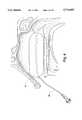
- FIG. 1illustrates the medical device of the present invention for absorbing body fluids, applying pressure to body walls in a body cavity and providing fluid to the body cavity;
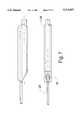
- FIG. 2is a cut-away view of the packing member that illustrates the delivery/draining tube section within the body of the packing member;
- FIG. 3illustrates a lateral cross-section of the packing member showing the delivery/draining tube disposed within the body of the packing member;
- FIG. 4illustrates the medical device in use in a nasal passage and the expanded state of the packing member for applying pressure to body cavity walls
- FIG. 5illustrates another embodiment of the present invention in which the packing member receives a venting tube, in addition to the delivery/draining tube;
- FIG. 6illustrates a lateral cross-section of the packing member showing both the venting tube and the delivery/draining tube
- FIG. 7is a bottom view of the packing member of FIG. 6 that illustrates the angled termination of the venting tube at its proximal end;
- FIG. 8illustrates the medical device that includes a venting tube positioned in a nasal passage for use in absorbing blood, applying pressure and providing delivery fluid;
- FIG. 9illustrates the packing member of FIG. 8 in an expanded state in the nasal passage
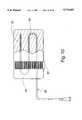
- FIG. 10illustrates another embodiment of the medical device in which the packing member is wider and in which the delivery/draining tube traverses the length of the packing member more than one time.
- the device 20includes a packing member or foam pad 24 that is generally elongated in shape. At the ends along its length, the packing member has rounded or curved corners to facilitate placement of the packing member 24 in a body cavity.
- the packing member 24is made of a material that absorbs fluids, including body fluids, such as blood.
- the packing member 24is made from a polyvinyl alcohol (PVA) or polyurethane foam or sponge, or other foam materials, which is formed or manufactured into desired sizes for placement in a particular body cavity. As illustrated in FIG. 1, the packing member 24 is initially in a compressed or unexpanded state.
- the packing member 24When the packing member 24 absorbs fluids, it is able to expand to a desired size. In one embodiment, the thickness along most of the length of the packing member 24, when placed in a body cavity, expands upon receiving fluid to about 1.5-7 times its compressed or unexpanded state. As can be understood, the portions of the packing member that expand are dependent upon their location in the body cavity. Little or no expansion occurs of those portions of the packing member 24 that contact a wall of the body cavity.
- the medical device 20also includes a delivery/draining tube 28, which is able to carry fluids both to and from the packing member 24.
- the delivery/draining tube 28has a channel section 32 that is disposed in a channel 36 provided or formed in the body of the packing member 24.
- the channel section 32is fixedly held in the channel 36, i.e., it does not slide nor is there any intended relative movement between the packing member 24 and the channel section 32.
- the fixed attachmentis accomplished, at least in part, by providing the width or diameter of the channel 36 so that it is less than the outside diameter of the channel section 32.
- the channel section 32has the same diameter and is integral with the remaining portions of the delivery/draining tube 28.
- the delivery/draining tube 28In order for the delivery/draining tube 28 to transfer fluid relative to the packing member 24, it includes at least one hole through which fluids are able to pass. In the embodiment of FIG. 2, a plurality of holes 40 are illustrated.
- the holes 40are provided throughout the length of the channel section 32 and are also provided along the entire outer periphery or circumference of the channel section 32.
- the fluid transfer relative to the holes 40can be bi-directional. More specifically, excess body fluid, such as blood, that is present in the body cavity having the packing member 24, is absorbed by the packing member 24 and passes inwardly of its body to the channel 36 where such fluid passes through the holes 40. Such fluid can be carried or drawn along the delivery/draining tube 28 away from the packing member 24. Alternatively, the holes 40 are able to pass a delivery fluid that is carried to the packing member 24.
- the channel section 32has a plugged end 44 that terminates the delivery/draining tube 28. The plugged end 44 is formed by creating a knot in the channel section and while this end is outside of the distal end 48 of the packing member. After the knot is formed, the knot is pulled back into or at the distal end 48.
- the length of the channel section 32 and/or the number of holes 40can differ.
- the channel section 32 of the delivery/draining tube 28might be less than the length of the packing member 24, such as even less than one half the length of the packing member 24.
- the length of the channel section 32may essentially be the same length as illustrated in FIG. 2; however, the spacing between holes may be greater and/or the number of holes may be more or less than that illustrated in FIG. 2.
- the number of holes 40 at one portion of the channel section 32may be greater than at other portions thereof whereby greater fluid transfer occurs at such portions.
- the diameter of the delivery/draining tube channel section 32is at least 5 percent of the thickness of the packing member in its compressed or unexpanded state and the diameter of the delivery/draining channel section 32 is no greater than about 80 percent of the thickness of the packing member 24 in its compressed or unexpanded state.
- the amount of the packing member 24 that surrounds the channel section 32 of the delivery/draining tube 28is about 1-9 millimeters.
- the packing member 24, especially in an application as a nasal packhas substantially the same thickness throughout a substantial majority, at least 75 percent, of its length when the packing member is in its compressed state.
- the length of the delivery/draining tubewhen the medical device 20 is used in connection with a nasal application, it is preferred that the length be sufficient to enable portions of the delivery/draining tube 28 to be placed over the ear of the patient and attached to the head of the patient. In many applications, the length of the delivery/draining tube 28 is at least twice the length of the packing member 24.
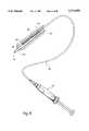
- the medical device 20also includes a fluid transfer unit 52 that is able to deliver and remove fluids using the delivery/draining tube 28. More specifically, the fluid transfer unit 52 is able to operate in one of two selected modes, namely: transferring fluids to the packing member 24 or transferring fluids from the packing member 24. In delivering fluids to the packing member 24 and thereby to the body cavity in which the packing member 24 is located, the fluid transfer unit 52 has a fluid with desired characteristics or properties that is to be delivered to the body cavity, such as a saline solution, water or other useful or treating fluid.
- the fluid transfer unit 52draws or creates a negative pressure to enable fluids, such as excess blood, to pass from the packing member through the holes 40 and along the delivery/draining tube 28 to the fluid transfer unit 52.
- the fluids drawn into the fluid transfer unit 52can include both body fluids and previously delivered fluids from the fluid transfer unit 52.
- the fluid transfer unit 52is a syringe or syringe-like member having a chamber 56 for containing a fluid to be delivered to the packing member 24 or for containing draining fluids from the packing member 24. At one end of the chamber 56 is a luer member 62 to which the end 64 of the delivery/draining tube 28 is connected.
- the chamber 56slidably, but sealingly, receives a plunger 68, which is useful in forcing an irrigating fluid from the chamber 56 to the packing member 24 along the length of the delivery/draining tube 28.
- a plunger 68which is useful in forcing an irrigating fluid from the chamber 56 to the packing member 24 along the length of the delivery/draining tube 28.
- pulling on the syringe plunger in an opposite directionis useful in drawing draining fluid in a direction from the packing member 24 to the chamber 56.
- the fluid transfer unit 52includes a medicine container or bulb, which is able to hold a substantial dosage or amount of a medicine or other healing-type fluid.
- FIG. 4illustrates the packing member 24 in an expanded state in a body cavity and applying pressure to at least one wall of the body cavity.
- This particular body cavityis a nasal passage where it is desirable to control hemostasis.
- the packing member 24has received body fluid, such as blood, and absorbs the same.
- body fluidsuch as blood
- the packing member 24changes from its compressed state to its expanded state.
- the packing member 24applies the desired pressure to the one or more body walls in the body cavity.
- the absorbed body fluidmay not be sufficient to expand the packing member 24 to its desired size in order to apply the desired or necessary pressure.
- the user or practitionercauses desired fluid to be delivered from the fluid transfer unit 52 to the channel section 32 and into the packing member 24 through the one or more holes 40.
- desired fluidenables the packing member 24 to expand to its desired or necessary size.
- the volume of the delivered fluid for achieving the desired expansionis greater than the volume of the body fluid absorbed by the packing member 24.
- the amount of pressure applied to at least one body wall of the body cavityis at least 2.3 psi and no greater than about 4.8 psi.
- the packing member 24is applying the desired pressure, it is in contact with the body wall and any body fluids that may still continue to exit from the body wall are immediately absorbed by the packing member 24 without traversing any space between the packing member 24 and the body wall. Additionally, when the packing member 24 has expanded and is properly performing its packing function, especially in the application of the present invention as a nasal pack, the tube length is sufficient to position portions thereof about the ear of the patient for positioning thereof in order to hold the delivery/draining tube 28 adjacent to the patient's head.
- the packing member 24performing its pressure application function, it is often necessary or desirable to provide a fluid, e.g., an antibiotic, an anesthetic, a decongestant or an irrigating fluid, that contributes to the treating or healing process associated with the body cavity in which the packing member 24 is disposed.
- a fluide.g., an antibiotic, an anesthetic, a decongestant or an irrigating fluid
- the fluidis supplied by the fluid transfer unit 52 through the delivery/draining tube 28 to the packing member 24. From the packing member 24, this treating fluid is received by the cavity as it passes or seeps from the packing member 24.
- the fluid transfer unit 52is used, in combination with the channel section 32 and other portions of the delivery/draining tube 28, to remove fluids so that the packing member 24 can continue to absorb more fluids.
- the present inventionis the ability to remove the packing member 24 from the body cavity while substantially reducing or even eliminating discomfort or trauma to the patient.
- removal of the packsuch as a nasal pack
- the method of the present inventioninvolves supplying a rehydrating fluid, such as a friction reducing fluid or other type fluid, that provides a lining between the body cavity wall and the packing member 24 for reducing friction between the packing member 24 and the wall. This fluid is supplied essentially immediately before the packing member is removed from the body cavity.
- the packing memberreceives rehydrating fluid from the fluid transfer unit 52.
- the packing member 24can be more readily manipulated to be removed without discomfort from the body cavity.
- Such removal after delivery of the rehydrating fluid for such a purposeis accomplished within at least about ten minutes, preferably within at least about five minutes, after the supplying of such irrigating fluid to the packing member.
- the volume of such fluid that is absorbed by the packing member 24is less than that absorbed by the packing member 24 when it was initially expanded for purposes of applying the necessary or desired pressure to the body cavity wall or walls.
- FIG. 5another embodiment of the medical device 20 is illustrated.
- This embodimentis the same as that of FIG. 1 except that a venting tube 70 is provided within the body of the packing member 24.
- the channel 36has a greater diameter or size to accommodate the width or diameter of the venting tube 70.
- the venting tube 70is useful in permitting the patient to continue to breathe when the medical device 20 is used in a nasal body cavity. Consequently, by means of the venting tube 70, the patient is still able to breathe through his or her nose.
- the venting tube 70includes a distal end 74 that extends from beyond the distal end 48 of the packing member 24.
- the proximal end 78 of the venting tube 70does terminate at or near the opposite end of the packing member 24. As seen in FIG.
- the venting tube 70has a diameter that is typically greater than the diameter of the delivery/draining tube channel section 32.
- FIG. 7illustrates a bottom view of the preferred embodiment that includes the venting tube 70, in which the proximal end 78 thereof is formed or cut at an angle. Consistent with this shape, the proximal end of the packing member 24 is also formed or cut at an angle that corresponds with the angle of the proximal end 78 of the venting tube 70. This configuration better permits the patient to breathe through his or her nose, while avoiding a potential blocking of this end of the venting tube 70 by portions of the body cavity walls.
- FIGS. 8 and 9illustrate a use of this particular medical device 20 in a nasal passage.
- the insertion, use and removal of the medical device 20 of this embodimentis the same, except for the functions or features associated with the venting tube 70. That is, the packing member 24 is able to contact one or more walls in the body cavity and apply pressure, while the packing member is useful in absorbing fluid to assist in the removal or delivery of fluids relative to the body cavity.
- the present inventionhas utility or applications in a variety of body cavities of differing sizes. Another embodiment is useful in connection with wounds or other breaches in the body and where the medical device 20 is located outside of such a cavity or wound.
- the packing member 24is relatively wide to permit the delivery/draining tube 28 to substantially traverse the length of the packing member 24 more than one time.
- the packing member 24, together with the delivery/draining tube 28 having the channel section 32,is able to deliver and remove fluids.
- the packing member 24is placed over a wound that is intended to receive an irrigating fluid, or alternatively, from which fluids are to be drained, such as blood.
- a strap 82 or other connectoris joined to the packing member 24.
- the strap 82is useful in affixing the packing member 24 to a body part, such as an arm having a wound therein.
- this deviceis located within a breech in the body where it is able to absorb blood or other body fluid for withdrawal thereof. Additionally or alternatively, a desired fluid can be supplied to the breech using the packing member 24.
Landscapes
- Health & Medical Sciences (AREA)
- Life Sciences & Earth Sciences (AREA)
- Heart & Thoracic Surgery (AREA)
- Engineering & Computer Science (AREA)
- Biomedical Technology (AREA)
- Animal Behavior & Ethology (AREA)
- General Health & Medical Sciences (AREA)
- Public Health (AREA)
- Veterinary Medicine (AREA)
- Surgery (AREA)
- Vascular Medicine (AREA)
- Hematology (AREA)
- Anesthesiology (AREA)
- Reproductive Health (AREA)
- Nuclear Medicine, Radiotherapy & Molecular Imaging (AREA)
- Medical Informatics (AREA)
- Molecular Biology (AREA)
- Biophysics (AREA)
- Pulmonology (AREA)
- Infusion, Injection, And Reservoir Apparatuses (AREA)
Abstract
Description
Claims (5)
Priority Applications (3)
| Application Number | Priority Date | Filing Date | Title |
|---|---|---|---|
| US08/561,869US5713855A (en) | 1995-11-22 | 1995-11-22 | Pressure applying fluid transfer medical method |
| US08/649,997US5827224A (en) | 1995-11-22 | 1996-05-16 | Pressure applying fluid transfer medical device |
| US09/169,741US6123697A (en) | 1995-11-22 | 1998-10-08 | Pressure applying fluid transfer method |
Applications Claiming Priority (1)
| Application Number | Priority Date | Filing Date | Title |
|---|---|---|---|
| US08/561,869US5713855A (en) | 1995-11-22 | 1995-11-22 | Pressure applying fluid transfer medical method |
Related Child Applications (1)
| Application Number | Title | Priority Date | Filing Date |
|---|---|---|---|
| US08/649,997Continuation-In-PartUS5827224A (en) | 1995-11-22 | 1996-05-16 | Pressure applying fluid transfer medical device |
Publications (1)
| Publication Number | Publication Date |
|---|---|
| US5713855Atrue US5713855A (en) | 1998-02-03 |
Family
ID=24243821
Family Applications (1)
| Application Number | Title | Priority Date | Filing Date |
|---|---|---|---|
| US08/561,869Expired - LifetimeUS5713855A (en) | 1995-11-22 | 1995-11-22 | Pressure applying fluid transfer medical method |
Country Status (1)
| Country | Link |
|---|---|
| US (1) | US5713855A (en) |
Cited By (23)
| Publication number | Priority date | Publication date | Assignee | Title |
|---|---|---|---|---|
| US6123697A (en)* | 1995-11-22 | 2000-09-26 | Shippert; Ronald D. | Pressure applying fluid transfer method |
| US6191341B1 (en) | 1998-04-21 | 2001-02-20 | Ronald D. Shippert | Medical absorbent pack substantially free of unwanted adhesion properties |
| US6361521B1 (en) | 1998-11-03 | 2002-03-26 | Grant C. Erickson | Nasal irrigation system |
| US6537265B2 (en)* | 2001-06-08 | 2003-03-25 | Health Research, Inc. | Method for nasal application of a medicinal substance |
| US6536437B1 (en)* | 1999-10-29 | 2003-03-25 | Branislav M. Dragisic | Cuffed nasal airway and anesthetic wand system |
| US20050288620A1 (en)* | 2004-06-28 | 2005-12-29 | Shippert Ronald D | Nose pack method and apparatus |
| US20090005763A1 (en)* | 2004-08-04 | 2009-01-01 | Exploramed Nc1, Inc. | Implantable Devices and Methods for Delivering Drugs and Other Substances to Treat Sinusitis and Other Disorders |
| US20090017090A1 (en)* | 2006-07-10 | 2009-01-15 | Arensdorf Patrick A | Devices and methods for delivering active agents to the osteomeatal complex |
| US20090177272A1 (en)* | 2007-12-18 | 2009-07-09 | Abbate Anthony J | Self-expanding devices and methods therefor |
| US20090227945A1 (en)* | 2005-04-04 | 2009-09-10 | Eaton Donald J | Device and methods for treating paranasal sinus conditions |
| US20090306575A1 (en)* | 2008-06-09 | 2009-12-10 | Ms. Merrie East | Disposable nose pack for nosebleeds |
| US20100043197A1 (en)* | 2008-08-01 | 2010-02-25 | Abbate Anthony J | Methods and devices for crimping self-expanding devices |
| US20110125091A1 (en)* | 2009-05-15 | 2011-05-26 | Abbate Anthony J | Expandable devices and methods therefor |
| US9138569B2 (en) | 2012-02-29 | 2015-09-22 | SinuSys Corporation | Devices and methods for dilating a paranasal sinus opening and for treating sinusitis |
| US20160184564A1 (en)* | 2014-12-31 | 2016-06-30 | Michael R. Spearman | Intranasal delivery device and method of material delivery |
| US9498239B2 (en) | 2010-08-30 | 2016-11-22 | SinuSys Corporation | Devices and methods for inserting a sinus dilator |
| US9687263B2 (en) | 2013-05-30 | 2017-06-27 | SinuSys Corporation | Devices and methods for inserting a sinus dilator |
| US10232152B2 (en) | 2013-03-14 | 2019-03-19 | Intersect Ent, Inc. | Systems, devices, and method for treating a sinus condition |
| US10736792B1 (en)* | 2019-04-29 | 2020-08-11 | Robert E. Fischell | Means and method to stop bleeding from the nose |
| US11291812B2 (en) | 2003-03-14 | 2022-04-05 | Intersect Ent, Inc. | Sinus delivery of sustained release therapeutics |
| US20220133282A1 (en)* | 2018-09-28 | 2022-05-05 | Achilleus LLC | Secure device for delivering medications |
| US12064577B2 (en) | 2015-01-22 | 2024-08-20 | Intersect Ent, Inc. | Drug-coated balloon |
| US12403291B2 (en) | 2019-08-30 | 2025-09-02 | Intersect Ent, Inc. | Submucosal bioresorbable drug eluting platform |
Citations (14)
| Publication number | Priority date | Publication date | Assignee | Title |
|---|---|---|---|---|
| US1355846A (en)* | 1920-02-06 | 1920-10-19 | David A Rannells | Medical appliance |
| US3049125A (en)* | 1960-03-28 | 1962-08-14 | Kriwkowitsch George | Nose packing device |
| US3570494A (en)* | 1968-12-16 | 1971-03-16 | George H Gottschalk | Nasal tampon |
| US4030504A (en)* | 1975-08-15 | 1977-06-21 | Doyle Donald E | Nasal hemostat and method of construction of nasal hemostat |
| US4883465A (en)* | 1988-05-24 | 1989-11-28 | Brennan H George | Nasal tampon and method for using |
| US4950280A (en)* | 1988-08-02 | 1990-08-21 | Brennan H George | Nasal tampon having a counter weight |
| US5011474A (en)* | 1988-05-24 | 1991-04-30 | Brennan H George | Methods for controlling nasal hemorrhaging |
| EP0467516A1 (en)* | 1990-07-20 | 1992-01-22 | Cabot Technology Corporation | Hemostatic stent |
| US5308338A (en)* | 1993-04-22 | 1994-05-03 | Helfrich G Baird | Catheter or the like with medication injector to prevent infection |
| US5324518A (en)* | 1989-12-08 | 1994-06-28 | Biosynthesis, Inc. | Implantable structure for containing substances for delivery to a body |
| US5336163A (en)* | 1993-01-06 | 1994-08-09 | Smith & Nephew Richards, Inc. | Expandable nasal stent |
| US5358494A (en)* | 1989-07-11 | 1994-10-25 | Svedman Paul | Irrigation dressing |
| US5370656A (en)* | 1993-02-26 | 1994-12-06 | Merocel Corporation | Throat pack |
| US5374261A (en)* | 1990-07-24 | 1994-12-20 | Yoon; Inbae | Multifunctional devices for use in endoscopic surgical procedures and methods-therefor |
- 1995
- 1995-11-22USUS08/561,869patent/US5713855A/ennot_activeExpired - Lifetime
Patent Citations (14)
| Publication number | Priority date | Publication date | Assignee | Title |
|---|---|---|---|---|
| US1355846A (en)* | 1920-02-06 | 1920-10-19 | David A Rannells | Medical appliance |
| US3049125A (en)* | 1960-03-28 | 1962-08-14 | Kriwkowitsch George | Nose packing device |
| US3570494A (en)* | 1968-12-16 | 1971-03-16 | George H Gottschalk | Nasal tampon |
| US4030504A (en)* | 1975-08-15 | 1977-06-21 | Doyle Donald E | Nasal hemostat and method of construction of nasal hemostat |
| US5011474A (en)* | 1988-05-24 | 1991-04-30 | Brennan H George | Methods for controlling nasal hemorrhaging |
| US4883465A (en)* | 1988-05-24 | 1989-11-28 | Brennan H George | Nasal tampon and method for using |
| US4950280A (en)* | 1988-08-02 | 1990-08-21 | Brennan H George | Nasal tampon having a counter weight |
| US5358494A (en)* | 1989-07-11 | 1994-10-25 | Svedman Paul | Irrigation dressing |
| US5324518A (en)* | 1989-12-08 | 1994-06-28 | Biosynthesis, Inc. | Implantable structure for containing substances for delivery to a body |
| EP0467516A1 (en)* | 1990-07-20 | 1992-01-22 | Cabot Technology Corporation | Hemostatic stent |
| US5374261A (en)* | 1990-07-24 | 1994-12-20 | Yoon; Inbae | Multifunctional devices for use in endoscopic surgical procedures and methods-therefor |
| US5336163A (en)* | 1993-01-06 | 1994-08-09 | Smith & Nephew Richards, Inc. | Expandable nasal stent |
| US5370656A (en)* | 1993-02-26 | 1994-12-06 | Merocel Corporation | Throat pack |
| US5308338A (en)* | 1993-04-22 | 1994-05-03 | Helfrich G Baird | Catheter or the like with medication injector to prevent infection |
Cited By (57)
| Publication number | Priority date | Publication date | Assignee | Title |
|---|---|---|---|---|
| US6123697A (en)* | 1995-11-22 | 2000-09-26 | Shippert; Ronald D. | Pressure applying fluid transfer method |
| US6191341B1 (en) | 1998-04-21 | 2001-02-20 | Ronald D. Shippert | Medical absorbent pack substantially free of unwanted adhesion properties |
| US6361521B1 (en) | 1998-11-03 | 2002-03-26 | Grant C. Erickson | Nasal irrigation system |
| US6536437B1 (en)* | 1999-10-29 | 2003-03-25 | Branislav M. Dragisic | Cuffed nasal airway and anesthetic wand system |
| US6537265B2 (en)* | 2001-06-08 | 2003-03-25 | Health Research, Inc. | Method for nasal application of a medicinal substance |
| US11291812B2 (en) | 2003-03-14 | 2022-04-05 | Intersect Ent, Inc. | Sinus delivery of sustained release therapeutics |
| US7294138B2 (en)* | 2004-06-28 | 2007-11-13 | Shippert Ronald D | Nose pack method and apparatus |
| US20050288620A1 (en)* | 2004-06-28 | 2005-12-29 | Shippert Ronald D | Nose pack method and apparatus |
| US9084876B2 (en) | 2004-08-04 | 2015-07-21 | Acclarent, Inc. | Implantable devices and methods for delivering drugs and other substances to treat sinusitis and other disorders |
| US20090005763A1 (en)* | 2004-08-04 | 2009-01-01 | Exploramed Nc1, Inc. | Implantable Devices and Methods for Delivering Drugs and Other Substances to Treat Sinusitis and Other Disorders |
| US9039680B2 (en)* | 2004-08-04 | 2015-05-26 | Acclarent, Inc. | Implantable devices and methods for delivering drugs and other substances to treat sinusitis and other disorders |
| US9039657B2 (en) | 2004-08-04 | 2015-05-26 | Acclarent, Inc. | Implantable devices and methods for delivering drugs and other substances to treat sinusitis and other disorders |
| US11123091B2 (en) | 2005-04-04 | 2021-09-21 | Intersect Ent, Inc. | Device and methods for treating paranasal sinus conditions |
| US20090227945A1 (en)* | 2005-04-04 | 2009-09-10 | Eaton Donald J | Device and methods for treating paranasal sinus conditions |
| US9585681B2 (en)* | 2005-04-04 | 2017-03-07 | Intersect Ent, Inc. | Device and methods for treating paranasal sinus conditions |
| US20110004192A1 (en)* | 2005-04-04 | 2011-01-06 | Eaton Donald J | Device and methods for treating paranasal sinus conditions |
| US8740839B2 (en) | 2005-04-04 | 2014-06-03 | Intersect Ent, Inc. | Device and methods for treating paranasal sinus conditions |
| US8337454B2 (en) | 2005-04-04 | 2012-12-25 | Intersect Ent, Inc. | Device and methods for treating paranasal sinus conditions |
| US8858974B2 (en) | 2005-04-04 | 2014-10-14 | Intersect Ent, Inc. | Device and methods for treating paranasal sinus conditions |
| US20090306624A1 (en)* | 2006-07-10 | 2009-12-10 | Sinexus, Inc. | Devices and methods for delivering active agents to the osteomeatal complex |
| US8802131B2 (en) | 2006-07-10 | 2014-08-12 | Intersect Ent, Inc. | Devices and methods for delivering active agents to the osteomeatal complex |
| US20090017090A1 (en)* | 2006-07-10 | 2009-01-15 | Arensdorf Patrick A | Devices and methods for delivering active agents to the osteomeatal complex |
| US8535707B2 (en) | 2006-07-10 | 2013-09-17 | Intersect Ent, Inc. | Devices and methods for delivering active agents to the osteomeatal complex |
| US8986341B2 (en) | 2007-12-18 | 2015-03-24 | Intersect Ent, Inc. | Self-expanding devices and methods therefor |
| US11654216B2 (en) | 2007-12-18 | 2023-05-23 | Intersect Ent, Inc. | Self-expanding devices and methods therefor |
| US8585730B2 (en) | 2007-12-18 | 2013-11-19 | Intersect Ent, Inc. | Self-expanding devices and methods therefor |
| US20090198179A1 (en)* | 2007-12-18 | 2009-08-06 | Abbate Anthony J | Delivery devices and methods |
| US11497835B2 (en) | 2007-12-18 | 2022-11-15 | Intersect Ent, Inc. | Self-expanding devices and methods therefor |
| US11826494B2 (en) | 2007-12-18 | 2023-11-28 | Intersect Ent, Inc. | Self-expanding devices and methods therefor |
| US8585731B2 (en) | 2007-12-18 | 2013-11-19 | Intersect Ent, Inc. | Self-expanding devices and methods therefor |
| US20090177272A1 (en)* | 2007-12-18 | 2009-07-09 | Abbate Anthony J | Self-expanding devices and methods therefor |
| US11110210B2 (en) | 2007-12-18 | 2021-09-07 | Intersect Ent, Inc. | Self-expanding devices and methods therefor |
| US10471185B2 (en) | 2007-12-18 | 2019-11-12 | Intersect Ent, Inc. | Self-expanding devices and methods therefor |
| US10010651B2 (en) | 2007-12-18 | 2018-07-03 | Intersect Ent, Inc. | Self-expanding devices and methods therefor |
| US20090306575A1 (en)* | 2008-06-09 | 2009-12-10 | Ms. Merrie East | Disposable nose pack for nosebleeds |
| US8604267B2 (en) | 2008-06-09 | 2013-12-10 | Merrie K. East | Disposable nose pack for nosebleeds |
| US8763222B2 (en) | 2008-08-01 | 2014-07-01 | Intersect Ent, Inc. | Methods and devices for crimping self-expanding devices |
| US9782283B2 (en) | 2008-08-01 | 2017-10-10 | Intersect Ent, Inc. | Methods and devices for crimping self-expanding devices |
| US20100043197A1 (en)* | 2008-08-01 | 2010-02-25 | Abbate Anthony J | Methods and devices for crimping self-expanding devices |
| US10357640B2 (en) | 2009-05-15 | 2019-07-23 | Intersect Ent, Inc. | Expandable devices and methods for treating a nasal or sinus condition |
| US20110125091A1 (en)* | 2009-05-15 | 2011-05-26 | Abbate Anthony J | Expandable devices and methods therefor |
| US11484693B2 (en) | 2009-05-15 | 2022-11-01 | Intersect Ent, Inc. | Expandable devices and methods for treating a nasal or sinus condition |
| US9498239B2 (en) | 2010-08-30 | 2016-11-22 | SinuSys Corporation | Devices and methods for inserting a sinus dilator |
| US9629644B2 (en) | 2010-08-30 | 2017-04-25 | SinuSys Corporation | Devices and methods for dilating a paranasal sinus opening and for treating sinusitis |
| US9149616B2 (en) | 2012-02-29 | 2015-10-06 | SinuSys Corporation | Devices and methods for dilating a paranasal sinus opening and for treating sinusitis |
| US9138569B2 (en) | 2012-02-29 | 2015-09-22 | SinuSys Corporation | Devices and methods for dilating a paranasal sinus opening and for treating sinusitis |
| US9504812B2 (en) | 2012-02-29 | 2016-11-29 | SinuSys Corporation | Devices and methods for dilating a paranasal sinus opening and for treating sinusitis |
| US9597485B2 (en) | 2012-02-29 | 2017-03-21 | SinuSys Corporation | Devices and methods for dilating a paranasal sinus opening and for treating sinusitis |
| US10406332B2 (en) | 2013-03-14 | 2019-09-10 | Intersect Ent, Inc. | Systems, devices, and method for treating a sinus condition |
| US10232152B2 (en) | 2013-03-14 | 2019-03-19 | Intersect Ent, Inc. | Systems, devices, and method for treating a sinus condition |
| US11672960B2 (en) | 2013-03-14 | 2023-06-13 | Intersect Ent, Inc. | Systems, devices, and method for treating a sinus condition |
| US9687263B2 (en) | 2013-05-30 | 2017-06-27 | SinuSys Corporation | Devices and methods for inserting a sinus dilator |
| US20160184564A1 (en)* | 2014-12-31 | 2016-06-30 | Michael R. Spearman | Intranasal delivery device and method of material delivery |
| US12064577B2 (en) | 2015-01-22 | 2024-08-20 | Intersect Ent, Inc. | Drug-coated balloon |
| US20220133282A1 (en)* | 2018-09-28 | 2022-05-05 | Achilleus LLC | Secure device for delivering medications |
| US10736792B1 (en)* | 2019-04-29 | 2020-08-11 | Robert E. Fischell | Means and method to stop bleeding from the nose |
| US12403291B2 (en) | 2019-08-30 | 2025-09-02 | Intersect Ent, Inc. | Submucosal bioresorbable drug eluting platform |
Similar Documents
| Publication | Publication Date | Title |
|---|---|---|
| US6123697A (en) | Pressure applying fluid transfer method | |
| US5713855A (en) | Pressure applying fluid transfer medical method | |
| US4883465A (en) | Nasal tampon and method for using | |
| US5011474A (en) | Methods for controlling nasal hemorrhaging | |
| US6027478A (en) | Nasal cavity drainage and stoppage system | |
| US4895559A (en) | Nasal pack syringe | |
| JP3327921B2 (en) | Apparatus using drain pipe | |
| EP1165157B1 (en) | Apparatus and method for selectively delivering medication to a wall section of a body cavity or blood vessel | |
| US5299581A (en) | Intravaginal device | |
| JP3924033B2 (en) | Device for forming a hole in the tracheal wall | |
| EP0959936B1 (en) | System for aspirating and irrigating tract wounds | |
| US6526980B1 (en) | Cervical drug delivery system | |
| US6572628B2 (en) | Method and apparatus for placing a medical agent into a vessel of the body | |
| US3598118A (en) | Method of introducing an intravenous catheter into the vascular system | |
| US20170007801A1 (en) | Flushing device and a catheter kit comprising a flushing device | |
| US20070060884A1 (en) | Apparatus for insertion between a medical tube and a body tissue opening | |
| JP7361400B2 (en) | ear catheter | |
| WO1994019050A1 (en) | Throat pack | |
| JP2023516589A (en) | Pharmaceutical therapy system and method of using same | |
| JP6745336B2 (en) | A system to treat epistaxis | |
| WO2019046265A1 (en) | Postpartum hemorrhage balloon system | |
| EP3764929B1 (en) | Systems for treating the nasal cavity | |
| US6517509B1 (en) | Absorbent pack insertion into a human body cavity | |
| JPH09234206A (en) | Antibacterial member used as medical or surgical auxiliary means | |
| US20240197980A1 (en) | Deployable sponge system |
Legal Events
| Date | Code | Title | Description |
|---|---|---|---|
| STCF | Information on status: patent grant | Free format text:PATENTED CASE | |
| FPAY | Fee payment | Year of fee payment:4 | |
| FPAY | Fee payment | Year of fee payment:8 | |
| FPAY | Fee payment | Year of fee payment:12 | |
| AS | Assignment | Owner name:SHIPPERT ENTERPRISES, LLC, COLORADO Free format text:ASSIGNMENT OF ASSIGNORS INTEREST;ASSIGNOR:SHIPPERT, RONALD D., DR.;REEL/FRAME:036801/0206 Effective date:20151014 | |
| AS | Assignment | Owner name:WINTRUST BANK, ILLINOIS Free format text:SECURITY INTEREST;ASSIGNORS:SUMMIT MEDICAL, INC.;SHIPPERT ENTERPRISES, LLC;SANTA BARBARA MEDCO, INC.;REEL/FRAME:036810/0672 Effective date:20151015 | |
| AS | Assignment | Owner name:MADISON CAPITAL FUNDING LLC, AS AGENT, ILLINOIS Free format text:SECURITY INTEREST;ASSIGNOR:SHIPPERT ENTERPRISES, LLC;REEL/FRAME:046766/0346 Effective date:20180830 | |
| AS | Assignment | Owner name:SHIPPERT ENTERPRISES, LLC, COLORADO Free format text:PATENT RELEASE AND REASSIGNMENT;ASSIGNOR:WINTRUST BANK;REEL/FRAME:047044/0781 Effective date:20180830 Owner name:SUMMIT MEDICAL, INC., MINNESOTA Free format text:PATENT RELEASE AND REASSIGNMENT;ASSIGNOR:WINTRUST BANK;REEL/FRAME:047044/0781 Effective date:20180830 Owner name:SANTA BARBARA MEDCO, INC., MINNESOTA Free format text:PATENT RELEASE AND REASSIGNMENT;ASSIGNOR:WINTRUST BANK;REEL/FRAME:047044/0781 Effective date:20180830 | |
| AS | Assignment | Owner name:SUMMIT MEDICAL, LLC, ILLINOIS Free format text:RELEASE BY SECURED PARTY;ASSIGNOR:MADISON CAPITAL FUNDING LLC;REEL/FRAME:053613/0166 Effective date:20200825 Owner name:SHIPPERT ENTERPRISES, LLC, ILLINOIS Free format text:RELEASE BY SECURED PARTY;ASSIGNOR:MADISON CAPITAL FUNDING LLC;REEL/FRAME:053613/0166 Effective date:20200825 |