US5713794A - Simulator controlling device - Google Patents
Simulator controlling deviceDownload PDFInfo
- Publication number
- US5713794A US5713794AUS08/665,289US66528996AUS5713794AUS 5713794 AUS5713794 AUS 5713794AUS 66528996 AUS66528996 AUS 66528996AUS 5713794 AUS5713794 AUS 5713794A
- Authority
- US
- United States
- Prior art keywords
- player
- additional reaction
- controlling device
- reaction areas
- game
- Prior art date
- Legal status (The legal status is an assumption and is not a legal conclusion. Google has not performed a legal analysis and makes no representation as to the accuracy of the status listed.)
- Expired - Lifetime
Links
Images


Classifications
- A—HUMAN NECESSITIES
- A63—SPORTS; GAMES; AMUSEMENTS
- A63B—APPARATUS FOR PHYSICAL TRAINING, GYMNASTICS, SWIMMING, CLIMBING, OR FENCING; BALL GAMES; TRAINING EQUIPMENT
- A63B69/00—Training appliances or apparatus for special sports
- A63B69/18—Training appliances or apparatus for special sports for skiing
- A—HUMAN NECESSITIES
- A63—SPORTS; GAMES; AMUSEMENTS
- A63F—CARD, BOARD, OR ROULETTE GAMES; INDOOR GAMES USING SMALL MOVING PLAYING BODIES; VIDEO GAMES; GAMES NOT OTHERWISE PROVIDED FOR
- A63F13/00—Video games, i.e. games using an electronically generated display having two or more dimensions
- A63F13/20—Input arrangements for video game devices
- A63F13/24—Constructional details thereof, e.g. game controllers with detachable joystick handles
- A63F13/245—Constructional details thereof, e.g. game controllers with detachable joystick handles specially adapted to a particular type of game, e.g. steering wheels
- A—HUMAN NECESSITIES
- A63—SPORTS; GAMES; AMUSEMENTS
- A63F—CARD, BOARD, OR ROULETTE GAMES; INDOOR GAMES USING SMALL MOVING PLAYING BODIES; VIDEO GAMES; GAMES NOT OTHERWISE PROVIDED FOR
- A63F13/00—Video games, i.e. games using an electronically generated display having two or more dimensions
- A63F13/25—Output arrangements for video game devices
- A63F13/28—Output arrangements for video game devices responding to control signals received from the game device for affecting ambient conditions, e.g. for vibrating players' seats, activating scent dispensers or affecting temperature or light
- A63F13/285—Generating tactile feedback signals via the game input device, e.g. force feedback
- A—HUMAN NECESSITIES
- A63—SPORTS; GAMES; AMUSEMENTS
- A63F—CARD, BOARD, OR ROULETTE GAMES; INDOOR GAMES USING SMALL MOVING PLAYING BODIES; VIDEO GAMES; GAMES NOT OTHERWISE PROVIDED FOR
- A63F13/00—Video games, i.e. games using an electronically generated display having two or more dimensions
- A63F13/55—Controlling game characters or game objects based on the game progress
- A63F13/57—Simulating properties, behaviour or motion of objects in the game world, e.g. computing tyre load in a car race game
- A—HUMAN NECESSITIES
- A63—SPORTS; GAMES; AMUSEMENTS
- A63F—CARD, BOARD, OR ROULETTE GAMES; INDOOR GAMES USING SMALL MOVING PLAYING BODIES; VIDEO GAMES; GAMES NOT OTHERWISE PROVIDED FOR
- A63F13/00—Video games, i.e. games using an electronically generated display having two or more dimensions
- A63F13/80—Special adaptations for executing a specific game genre or game mode
- A63F13/807—Gliding or sliding on surfaces, e.g. using skis, skates or boards
- A—HUMAN NECESSITIES
- A63—SPORTS; GAMES; AMUSEMENTS
- A63B—APPARATUS FOR PHYSICAL TRAINING, GYMNASTICS, SWIMMING, CLIMBING, OR FENCING; BALL GAMES; TRAINING EQUIPMENT
- A63B21/00—Exercising apparatus for developing or strengthening the muscles or joints of the body by working against a counterforce, with or without measuring devices
- A63B21/02—Exercising apparatus for developing or strengthening the muscles or joints of the body by working against a counterforce, with or without measuring devices using resilient force-resisters
- A63B21/028—Exercising apparatus for developing or strengthening the muscles or joints of the body by working against a counterforce, with or without measuring devices using resilient force-resisters made of material having high internal friction, e.g. rubber, steel wool, intended to be compressed
- A—HUMAN NECESSITIES
- A63—SPORTS; GAMES; AMUSEMENTS
- A63F—CARD, BOARD, OR ROULETTE GAMES; INDOOR GAMES USING SMALL MOVING PLAYING BODIES; VIDEO GAMES; GAMES NOT OTHERWISE PROVIDED FOR
- A63F2300/00—Features of games using an electronically generated display having two or more dimensions, e.g. on a television screen, showing representations related to the game
- A63F2300/10—Features of games using an electronically generated display having two or more dimensions, e.g. on a television screen, showing representations related to the game characterized by input arrangements for converting player-generated signals into game device control signals
- A63F2300/1037—Features of games using an electronically generated display having two or more dimensions, e.g. on a television screen, showing representations related to the game characterized by input arrangements for converting player-generated signals into game device control signals being specially adapted for converting control signals received from the game device into a haptic signal, e.g. using force feedback
- A—HUMAN NECESSITIES
- A63—SPORTS; GAMES; AMUSEMENTS
- A63F—CARD, BOARD, OR ROULETTE GAMES; INDOOR GAMES USING SMALL MOVING PLAYING BODIES; VIDEO GAMES; GAMES NOT OTHERWISE PROVIDED FOR
- A63F2300/00—Features of games using an electronically generated display having two or more dimensions, e.g. on a television screen, showing representations related to the game
- A63F2300/10—Features of games using an electronically generated display having two or more dimensions, e.g. on a television screen, showing representations related to the game characterized by input arrangements for converting player-generated signals into game device control signals
- A63F2300/1062—Features of games using an electronically generated display having two or more dimensions, e.g. on a television screen, showing representations related to the game characterized by input arrangements for converting player-generated signals into game device control signals being specially adapted to a type of game, e.g. steering wheel
- A—HUMAN NECESSITIES
- A63—SPORTS; GAMES; AMUSEMENTS
- A63F—CARD, BOARD, OR ROULETTE GAMES; INDOOR GAMES USING SMALL MOVING PLAYING BODIES; VIDEO GAMES; GAMES NOT OTHERWISE PROVIDED FOR
- A63F2300/00—Features of games using an electronically generated display having two or more dimensions, e.g. on a television screen, showing representations related to the game
- A63F2300/60—Methods for processing data by generating or executing the game program
- A63F2300/64—Methods for processing data by generating or executing the game program for computing dynamical parameters of game objects, e.g. motion determination or computation of frictional forces for a virtual car
- A—HUMAN NECESSITIES
- A63—SPORTS; GAMES; AMUSEMENTS
- A63F—CARD, BOARD, OR ROULETTE GAMES; INDOOR GAMES USING SMALL MOVING PLAYING BODIES; VIDEO GAMES; GAMES NOT OTHERWISE PROVIDED FOR
- A63F2300/00—Features of games using an electronically generated display having two or more dimensions, e.g. on a television screen, showing representations related to the game
- A63F2300/80—Features of games using an electronically generated display having two or more dimensions, e.g. on a television screen, showing representations related to the game specially adapted for executing a specific type of game
- A63F2300/8041—Skating using skis, skates or board
- Y—GENERAL TAGGING OF NEW TECHNOLOGICAL DEVELOPMENTS; GENERAL TAGGING OF CROSS-SECTIONAL TECHNOLOGIES SPANNING OVER SEVERAL SECTIONS OF THE IPC; TECHNICAL SUBJECTS COVERED BY FORMER USPC CROSS-REFERENCE ART COLLECTIONS [XRACs] AND DIGESTS
- Y10—TECHNICAL SUBJECTS COVERED BY FORMER USPC
- Y10S—TECHNICAL SUBJECTS COVERED BY FORMER USPC CROSS-REFERENCE ART COLLECTIONS [XRACs] AND DIGESTS
- Y10S482/00—Exercise devices
- Y10S482/901—Exercise devices having computer circuitry
- Y10S482/902—Employing specific graphic or video display
Definitions
- a new apparatus for artificially playing a skiis proposed.
- This apparatuscomprises boards similar to ski plates on which a player gets.
- an improved ski game apparatushas been proposed in which input boards similar to ski plates are used as input means.
- a playercan play a virtual ski in a virtual three-dimensional space. The player's playing state is projected on a display.
- the input boardsforcedly return to their original positions such that the player can easily know the rectilinear direction during the game or such easily know the rectilinear direction during the game or such that the player can easily get on and off the input boards before the game starts and after the game is over.
- the swinging motion of the input boardsis limited by any limiting means within a given range and when the input boards collide against the limiting means, a large impact arises. It is therefore desired that a reaction force against the limiting means shall be given to the input boards while the input boards approach the limiting means. Such a reaction force can absorb the impact of the collision of the input boards with the limiting means.
- An object of the inventionis therefore to provide a simulator controlling device which can force a swinging member for directing it to a given direction and which can absorb an impact produced when the swinging motion of the swinging member is limited.
- the inventionprovides a simulator controlling device comprising a swinging member for controlling a virtual moving object in the right and left direction.
- the swinging memberis swung right and left within right and left limits.
- a first elastic meansforces and returns the swinging member to a neutral position within the right and left limits.
- a second elastic meansforces the swinging member toward the neutral position within right and left additional reaction areas.
- Each of the right and left additional reaction areasare formed from each of the right and left limits.
- the swinging memberis forced to its neutral position by the first elastic means.
- the second elastic meansforces the swinging member in addition to the first elastic means within right and left additional reaction areas.
- the right and left additional reaction areasare formed from the right and left limits.
- the swinging memberforcedly faces a given direction and the impact produced when the motion of the swinging member is limited can be absorbed. If such a device is applied, for example, to a ski game apparatus, therefore, the swinging member can preferably swing. A player can easily get on and off the swinging member.
- the right and left additional reaction areas provided by the second elastic meansare changed to expand to the neutral position at a non-playing time.
- the swinging memberis stabilized at the non-playing time.
- the right and left additional reaction areas provided by the second elastic meansexpand to the neutral position immediately before a play is over.
- the swinging memberis stabilized at a non-playing time.
- the inventioncan be applied to a game apparatus in which the play is to be finished after a virtual moving object enters the goal with the wined points and rank being displayed on a display.
- the right and left additional reaction areasstart to expand to the neutral position when the virtual moving object enters the goal.
- the right and left additional reaction areascontinue to expand while the wined points and rank are being displayed.
- the swinging memberis completely stabilized at the neutral position when the play is over.
- right and left additional reaction areasare changeable independently of each other.
- the areas at which reaction forces are given to the swinging member through the second elastic meanscan be set separately of each other.
- the right and left additional reaction areasare changed corresponding to a condition where the virtual moving object moves.
- the right and left additional reaction areaswill be approached to each other to narrow the area therebetween, where no reaction force is provided through the second elastic means.
- the area where the swinging member is easily swungwill be narrowed. This provides a player's feel as if his or her feet are carried off in the deep snow. If it is set that the snow surface is being hardened, the area between the right and left additional reaction areas is gradually widened to expand the area in which the swinging member is easily moved. This provides the player's feel as if he or she easily skis.
- one of the right and left additional reaction areas corresponding to the hilltopis approached to the neutral position while the other additional reaction area corresponding to the hill bottom is moved away from the neutral position.
- such a feel that one of the ski plates located on the hilltop side is less easily moved while the other ski plate located on the hill bottom side is more easily movedcan be provided.
- the slope becomes steeperone of the right and left additional reaction areas corresponding to the hilltop is further approached to the neutral position while the other additional reaction area corresponding the hill bottom is further moved away from the neutral position.
- Such a settingcan provide an actual skiing feel to the player.
- the right and left additional reaction areasare changed corresponding to a moving way of the virtual moving object.
- the right and left additional reaction areasare approached to each other to narrow the area where no reaction force is given from the second elastic means. This provides a feel in which the player less easily moves his or her ski plates.
- the virtual moving objectmoves on the snow at a lower speed, the right and left additional reaction areas are moved away from each other to widen the area where no reaction force is given from the second elastic means. This provides a feel in which the player more easily moves the ski plates.
- the right and left additional reaction areasare approached to each other to narrow the area where no reaction force is given from the second elastic means. This provides a feel in which the player less easily moves his or her ski plates. On the contrary, if the player selects shorter ski plates, the right and left additional reaction areas are moved away from each other to widen the area where no reaction force is given from the second elastic means. This provides a feel in which the player more easily moves the ski plates.
- FIG. 1is a plan view showing the internal structure of an oscillator
- FIG. 2is a side view of the oscillator of FIG. 1;
- FIG. 3is a plan view showing the movement of the oscillator of FIG. 1;
- FIG. 5is a plan view showing the movement of the oscillator
- FIG. 6is a plan view showing the movement of the oscillator
- FIG. 7Ais a longitudinal cross-section of a reaction generating section in the illustrated embodiment
- FIG. 7Bis a cross-sectional view taken along a line B--B in FIG. 7A;
- FIG. 7Cis a cross-sectional view taken along a line C--C in FIG. 7A;
- FIG. 8Ais a longitudinal cross-section of another reaction generating section
- FIG. 8Bis a cross-sectional view taken along a line D--D in FIG. 8A;
- FIG. 9is a perspective view of a ski game apparatus
- FIG. 10A and 10Bshow plan and side views of the ski game apparatus
- FIG. 11illustrates the swinging motion of the simulator controlling device
- FIG. 12A and 12Billustrate the edging motion of the steps in an input board of the simulator controlling device
- FIG. 13A and 13Billustrate the locus of the player in the game
- FIG. 14illustrates the details of a game scene
- FIG. 16A and 16Billustrate three-dimensional game scenes
- FIG. 17A, 17B and 17Cillustrate analog wave forms based on swing angles which are sensed by a swing sensor
- FIG. 18illustrates a game scene in which the player is performing a skating action
- FIG. 20illustrates another modified form of the illustrated embodiment
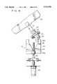
- the illustrated ski game apparatuscomprises an input board 120 imitating actual ski plates and a display 130 located in front of the input board 120.
- Two ski sticks 118 imitating actual ski sticksare fixedly mounted on a housing 110. A player is to support his or her own body by grasping the right and left sticks 118.
- the playerstands on right and left steps 120a and 120b with both of his or her feet, these steps being mounted on the input board 120.
- the right and left sticks 118grasped by the player, he or she supports his or her own body and performs turns as in the actual skiing.
- FIG. 11illustrates the swing action on the input board 120.
- the input board 120is located adjacent to the floor.
- the input board 120is also pivotally mounted on the oscillator 10 for performing the swing action.
- the swing actionis accomplished about a rotating shaft 14 (see FIG. 1) for the input board within the maximum swing angle ⁇ max in either of the right or left direction from a reference position.
- the swing angle ⁇is zero at the reference position.
- the input board 120 shown by solid line in FIG. 11is placed at the reference position.
- the reference positionis defined herein such that the overall body of the player faces a screen 130 when the player gets on the input board 120.
- the swing angle ⁇ in the swing actionis sensed by a swing sensor 18 (see FIG. 2) which is disposed in the oscillator 10.
- the swing sensor 18comprises a variable revolving type resistor such that the swing angle ⁇ of the input board 120 along the horizontal plane will be sensed as a resistance.
- the input board 120is forced to the reference position at which the swing angle ⁇ is equal to zero (the position of the input board shown by solid line in FIG. 11). As the swing angle ⁇ increases, the elastic force toward the reference position also increases. This can be accomplished by such means as will be described later. The player swings or oscillates the input board 120 in the right and left directions against the elastic force. Thus, the player can perform turns while feeling loads on both of his or her feet as in the actual skiing.
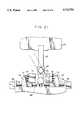
- FIG. 1is a plan view of the internal structure of the oscillator 10 while FIG. 2 is a side view thereof.
- the input board 120is restricted so that it will not oscillate.
- FIG. 3is also a plan view of the internal structure of the oscillator 10, differing from FIGS. 1 in the input board 120 being freely swung or oscillated.
- FIGS. 4is a side view of FIG. 3.
- the stopped element 32is disposed within an oscillation area 42 and an oscillation stopping area 44 which are defined by a stopper 40. More particularly, the roller 32a of the stopped element 32 is disposed within the oscillation stopping area 44.
- the stopper 40is of a plate-shaped configuration having a cut-out the width of which gradually increases toward the stopped element 32 to form the oscillation area 42. More particularly, the oscillation area 42 is cut out to have the maximum width adjacent to the end of the stopper 40 and to have the width gradually decreased from the end of the stopper 40.
- the oscillation stopping area 44is formed in the stopper 40 at a position most remote from the stopped element 32. The oscillation stopping area 44 has its width sufficient to receive the roller 32a leaving some clearance.
- the stopper 40can be moved toward or away from the stopped element 32.
- FIGS. 1 and 2show the stopper 40 at a position in which it is most close to the stopped element 32.
- FIGS. 3 and 4show the stopper 40 at a position in which it is most spaced away from the stopped element 32.
- the housing 110includes a motor 46 mounted therein.
- a motor 46mounted therein.
- On the top face of the stopper 40is mounted an engagin portion 40a which has a female screw.
- a rotating rod 48which has a male screw is rotatably driven by a motor 46. The stopper 40 can be moved forward and backward by the engagement of the female screw of the engaging portion 40a and the male screw of the rotating rod 48.
- the roller 32acan be freely moved within the oscillation area 42.
- the stopped element 32can be oscillated with the input board 120 within this range.
- the input board 120can be oscillated, as shown in FIG. 5.
- the stopper 40can be smoothly moved by rotating the rotating rod 48, the stopper 40 can be positioned not only at the position most remoted from the stopped element 32 as shown in FIG. 3, but also at any middle position. Since the notch forming the oscillation area 42 has inclined side edges, the oscillating range of the stopped element 32 can be varied depending on the relative position between the stopper 40 and the stopped element 32.
- a desired oscillating rangecan be provided. More particularly, the stopped element 32 and input board 120 will not be oscillated under such a condition that the roller 32a has been received in the oscillation stopping area 44 (see FIG. 1). As the stopper 40 is moving backward, the range within which the stopped element 32 and input board 120 can be oscillated gradually increases. In other words, this range gradually decreases as the stopper 40 is moving forward from its most retracted position (see FIG. 3). As the roller 32a has moved into the oscillation stopping area 44 (see FIG. 1), the stopped element 32 and input board 120 will be stopped in oscillation.
- the oscillation in the input board 120is gradually stopped, rather than rapidly stopped.
- a playergets on the input board 120 while playing a game and gets off after the game is over. Therefore, The input board 120 is gradually stopped so that any violent impact will not be given and the player can get off the input board 120 easily.
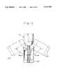
- FIGS. 7A, 7B and 7Cshow the reaction generating portion 20.
- the input board 120is inclined by the maximum angle (see FIG. 6).
- FIG. 7Ais a longitudinal cross-section of the reaction generating portion 20.
- FIG. 7Bis a cross-sectional view taken along a line B--B in FIG. 7A.
- FIG. 7Cis a cross-sectional view taken along a line C--C in FIG. 7A.
- the reaction generating portion 20comprises inner limiting portions 22 and 24, an outer limiting portion 26 and elastic portions 28 and 29.
- the outer limiting portion 26is a pipe having its square cross-section space where the inner limiting portions 22 and 24 is contained. More particularly, the outer limiting portion 26 is formed by a pair of pipe halves that are clamped with each other by means of bolts and nuts. The outer limiting portion 26 is positioned at a location where it has been rotated by 90 degrees relative to the inner limiting portions 22 and 24. In other words, the outer sides of the inner limiting portions 22 and 24 face the internal corners of the outer limiting portion 26 to form substantially triangular spaces therebetween.
- Elastic portions 28 or 29is pressed into the corresponding triangular space while being more or less compressed.
- the shape of the elastic portions 28 and 29is selected such that the triangular configuration can be maintained through a reaction produced when the elastic portion is pressed into the triangular space.
- the elastic portions 28 and 29are preferably formed of a elastic material having its particularly superior durability such as rubber or the like.
- the elastic portions 28are interposed under pressure between the outer limiting portion 26 and the inner limiting portion 22 while the elastic portions 29 are interposed under pressure between the outer limiting portion 26 and the inner limiting portion 24.
- the outer limiting portion 26connects the inner limiting portions 22 and 24 through the elastic portions 28 and 29.
- the outer limiting portion 26is not fixed to any other member.
- reaction generating portion 20functions as follows. All the corners of the inner limiting portions 22 and 24 are directed toward the input board 120 when the latter is in its upright position as shown in FIG. 2.
- the elastic portions 28are further compressed to increase the reaction force.
- the reaction forcefunctions to rotate the outer limiting portion 26 to such a state as shown in FIGS. 7A-7C (see FIG. 6).
- the rotation of the rotating shaft 14rotates the inner limiting portion 22 to compress the elastic portions 28.
- the compressed elastic portions 28rotates the outer limiting portion 26 with its reaction force.
- the rotation of the outer limiting portion 26causes the triangular spaces between the outer limiting portion 26 and the inner limiting portion 24 to be deformed, thereby compressing the elastic portions 29 in these triangular spaces.
- the reaction generating portion 20provides two-stage reaction generating means. One stage of it is provided by the inner limiting portion 22, the elastic portions 28 and the outer limiting portion 26. The other stage of it is provided by the inner limiting portion 24, the elastic portions 29 and the outer limiting portion 26.
- the oscillation angle providing the reaction forceis doubled by the two-stage reaction generating means in comparison with the reaction force by only one reaction generating means. More particularly, the first reaction force can be provided within a range of about 35 degrees by the inner limiting portions 22, the elastic portions 28 and the outer limiting portion 26.
- the second reaction forcecan be provided within a range of about 35 degrees by the inner limiting portion 24, the elastic portions 29 and the outer limiting portion 26.
- the total oscillation angleequal to about 70 degrees will be provided by the two-stage reaction forces.
- the elastic portions 28 and 29Since one of the elastic portion 28 and 29 is compressed within an oscillation angle of about 35 degrees, the elastic portions are less damaged than the case where all the elastic portions are compressed within an oscillation angle of about 70 degrees. Since the reaction force is provided by a restoring force produced when the elastic portions 28 and 29 are compressed, the reaction force will increase as the oscillation angle increases. In the embodiment, the oscillation angle to compress one of the elastic portions is smaller, thereby providing a less variable reaction force. In other words, a relatively constant reaction force can be provided.
- FIG. 8Ais a partial side view of the reaction generating portion 30 while FIG. 8B is a cross-sectional view taken along a line D--D in FIG. 8A.
- the reaction generating portion 30is mounted on the rotating shaft 14 and has a stopped element 32.
- the inclination of the stopped element 32is limited by a stopper 40 to limit the oscillation of the input board 120 (see FIGS. 1 to 6).
- the reaction generating portion 30movably supports the stopped element 32 and provides a reaction force when the stopped element 32 is inclined. More particularly, a square pipe-shaped outer limiting portion 36 is fixedly mounted on the rotating shaft 14 in which an inner limiting portion 34 is disposed. The top end of the inner limiting portion 34 fixedly supports the stopped element 32. As shown in FIG. 8B, elastic portions 38 are disposed in the triangular spaces that are formed between the outer sides of the inner limiting portion 34 and the internal corners of the outer limiting portion 36.
- reaction generating portion 30is substantially similar to one stage of the aforementioned two-stage reaction generating portion 20, but will not be further described.
- the stopped element 32is thus swung or oscillated by the reaction force from the reaction generating portion 30. As an external force is applied to the input board 120 to incline it from such a state that the stopped element 32 is restricted by the stopper 40 as shown in FIG. 5, the stopped element 32 will be inclined to swing the input board 120 as shown in FIG. 6.
- the roller 32aSince the roller 32a is received in the oscillation stopping area 44 under the state of FIG. 1, only the second and third states can be provided without the first state. More particularly, the additional reaction area becomes equal to the neutral position of the input board 120 since the roller 32a is located within the oscillation stopping area 44 of the minimum width. Therefore, the input board 120 is stabilized at the neutral position.
- FIGS. 12A and 12Bshow the detailed structure of the left and right steps 120a, 120b. Edging will be described with reference to FIGS. 12A and 12B.
- the input board 120 of this embodimentcomprises a pair of the left and right steps 120a, 120b, and a frame 123 which rotatably supports the left and right steps 120a, 120b through rotating shafts 128a and 128b, respectively.
- steps 120a and 120bare inclined by the player, he or she can perform an edging action.
- the edging actionis accomplished about the step rotating shafts 128a and 128b within the maximum inclination angle ⁇ max from a reference position in which the inclination angle ⁇ is equal to zero in such a state as shown by a two dot chain line in FIG. 12A.
- the reference positioncan be defined as a position wherein the left and right steps 120a, 120b are positioned flat relative to the frame 123.
- the left and right steps 120a, 120bare always forced toward the reference position in which the inclination angle ⁇ is equal to zero (a position in which the left and right steps 120a, 120b are shown by a two dot chain line in FIGS. 12A and 12B) through forcing means (not shown).
- a restoring force toward the reference positionincreases.
- the playercan perform the edging action while feeling loads on his or her feet as in the actual skiing, since the left and right steps 120a, 120b are swung or oscillated by the player against the aforementioned elastic force.
- FIGS. 13A and 13Bshow the locus of the virtual skier moving in a virtual three-dimensional space.
- the running state and locus of a skierare determined by turning motion of ski plates, topography and other natural conditions. Since the skier determines his or her running course by controlling the ski plates, the moving locus highly depends on the turning action of the ski plates.
- the turning actionis provided by the horizontal swing action and the vertical edging action.
- the locus thereofdraws such a gentler curve as shown in FIG. 13A, resulting in a smaller deceleration. If the virtual skier inclines the ski plates through a larger angle, the locus thereof draws such a sharper curve as shown in FIG. 13B, resulting in a larger deceleration.
- the curve drawn by the locus of the virtual skieris more sharpened and the deceleration decreases. Only when the player appropriately combines the swinging action with the edging action in the input board 120, the virtual skier can perform his or her quick passage through a desired course without running out of the course. This can provide a feel more similar to that of the actual skiing.
- the ski game machineWhen the player gets on the input board 120, he or she first throws a coin into a coin throwing portion (not shown) and then depresses selection buttons 112, 114 and a decision button 116 to select a game mode and a course.
- This embodimentprovides two game modes, a race mode and a time attack mode.
- a race modea competitive game in which the virtual skier competes with four computer skiers will be played.
- the time attack modeonly the virtual skier controlled by the player will play the game to obtain the shortest time, rather than competition with the computer skiers.
- this embodimentprovides three courses, junior, middle and senior.
- the gamestarts with a game scene 300 on a display 130.
- FIG. 14shows the details of such a game scene in this embodiment.
- the game scene 300includes a scene viewed by the virtual skier in his or her front in a preset three-dimensional game space. Such a scene is rirtual three-dimensional one corresponding to the course selected by the player.
- FIG. 16Aexemplifies a scene in a selected course.
- Information relating to the coursesis stored, as divided map information, in a map information storage section of a game computation section 400 as will be described.
- Information necessary to form the images of the courseis stored in an object image information storage section 260 of an image synthesis section 200 which will be also described. Based on the information, the scene viewed by the virtual skier in his or her front is computed and displayed.
- FIG. 15is a functional block diagram of an arcade ski game machine according to this embodiment.
- the arcade ski game machinecomprises a player's control section 140, a game computation section 400, an image synthesis section 200 and a display 130.
- the game computation section 400comprises a game space computation section 410, a map information storage section 430 and a mover information storage section 440.
- the game computation section 400performs various computation for the game on the basis of the input signals from the control section 140 and a preset game program.
- the resulting dataare then outputted toward the image synthesis section 200 for forming an image.
- the preset game programis stored in a storage section (not shown) in the game space computation section 410.
- the game space computation section 410computes the positional coordinates of the virtual skier controlled by the player on the basis of the game program, the control signals from the control section 140 and the skier information read out from the mover information storage section 440.
- the game space computation section 410also computes the positional coordinates of other virtual skiers on the basis of the game program and the mover information read out from the mover information storage section 440.
- a three-dimensional game spacewill be formed on the basis of the positional coordinates of the virtual skier controlled by the player and other virtual skiers as well as the map information read out from the map information storage section 430.
- the game sceneis supplied to the display at each time of 1/60 seconds.
- the game computation section 400sets a three-dimensional game space reflecting 1/60 seconds variable states according to the following manner.
- Information relating to the courses along which the player's skier movesis stored in the map information storage section 430 as divided map information about the plane coordinates of each point and the altitude of that point.
- the present position of the player's skieris stored in the mover information storage section 440 as the mover information in the three-dimensional coordinates.
- a start positionis decided depending on the course selected by the player.
- the coordinates of that start position in the three-dimensional spaceare initially set in the mover information storage section 440 as the present position of the player's skier.
- the information of the position of the player's skier in the mover information storage section 440subsequently updated depending on the computation result by the game space computation section 410 every 1/60 seconds.
- the game space computation section 410reads out the present position of the player's skier from the mover information storage section 440.
- the game space computation section 410further computes the variable position of the player's skier moving in the virtual three-dimensional space, based on the control signals from the control 140 through the turning action made by the player and the information of the topography and other natural conditions.
- Information of a natural conditionsuch as wind or the like is formed according to algorithm preset in the game program so that the natural condition can influence the moving action of the player's skier.
- this embodimentcomputes the state where the player's skier is going on skis in a given three-dimensional game space as shown in FIG. 16A.
- the resultsare outputted toward the image synthesis section 200.
- the game space computation section 410Since images are supplied to the display every 1/60 seconds, the game space computation section 410 performs the aforementioned computation every 1/60 seconds and outputs the result toward the image synthesis section 200.
- the object image information storage section 260has stored image information relating to the movers such as the skiers, snowed surfaces, hills, trees, rivers, buildings and others.
- the three-dimensional computation section 220reads out the image information corresponding to the input data (including the mover information and divided map information) from the object image information storage section 260.
- the read image informationset the game space as a set of polygons.
- the three-dimensional computation section 220also performs other processing such as clipping for removing data out of the visual field, perspective projection conversion into a screen coordinate system, sorting and others.
- the processed dataare then outputted toward the image forming section 240.
- the image forming section 240may form an image through a technique known as a texture mapping in which the image information of all the dots in each polygon has been stored in any suitable storage means such as ROM as texture information. The texture information is then read out from the ROM and mapped onto the polygon using texture coordinates given to each vertex of each polygon as an address.
- a texture mappingin which the image information of all the dots in each polygon has been stored in any suitable storage means such as ROM as texture information.
- the texture informationis then read out from the ROM and mapped onto the polygon using texture coordinates given to each vertex of each polygon as an address.
- a state as if the player goes on skis in the virtual three-dimensional game space 500can be simulated.
- the playercan freely slide in the virtual three-dimensional game space 500 shown in FIG. 16A and can also compete with the other skiers.
- a skierwill not stop as long as he or she goes from a higher place to a lower place. If he or she falls or goes out of the courser, he or she may stop. If an acceleration can be consciously attained by performing the skating input with both the feet of the player as in the actual skiing, the ski game machine will be improved in reality.
- the input meansincluded an input board that can be simultaneously actuated by both the feet of the player. This only permits the turning action in the skiing. Therefore, the prior art could not provide a skating action that is performed by both the feet of the player.
- the game machine of this embodimentcomprises a skating action judgment section 422 in the game space computation section 410.
- the skating action judgment section 422judges that the skating action is being performed only when the turning action of the input board 120 fulfills a preset requirement.
- the input board 120 used to performing the normal turn inputcan be also used to make the skating input through the player's feet without any modification. This can provide a ski game, snow board game or skate board game which is improved in reality.
- the skating action judgment section 422judges that the skating action is being performed only when four or more swings are detected by the swing sensor, each swing having a swing angle equal to or more than 70% of the maximum angle (70 degrees) and an interval between each swing being equal to or less than 0.8 seconds.
- the skating turncan be clearly distinguished from the normal turning action.
- FIGS. 17A, 17B and 17Care schematic analog diagrams of the swing angle ⁇ detected by the swing sensor.
- the horizontal axisrepresents time.
- the vertical axisrepresents the magnitude of the swing angle ⁇ relative to the reference position 0.
- the swing angle ⁇ measured from the reference position in the left directionis positive while the swing angle ⁇ measured from the reference position in the right direction is negative.
- FIG. 17Ais an analog wave form detected by the sensor 122 when each swing angle ⁇ is 90% of the maximum (70 degrees) and an interval between each swing is one second.
- FIG. 17Bis an analog wave form detected by the sensor 122 when each swing angle ⁇ is 60% of the maximum (70 degrees) and an interval between each swing is 0.5 seconds.
- FIG. 17Cis an analog wave form detected by the sensor 122 when each swing angle ⁇ is 90% of the maximum (70 degrees) and an interval between each swing is 0.5 seconds.
- the skating action judgment section 422judges that the skating action is being performed when such an analog wave form as shown in FIG. 17C is detected.
- the game machine of this embodimentfurther comprises a skating acceleration section 424 for consciously accelerating the player's skier based on the skating action.
- the skating acceleration section 424is responsive to the result of the skating action judgment section 422 and also the state of the player's skier in the virtual three-dimensional space for accelerating the player's skier in the virtual three-dimensional game space.
- the skating acceleration section 424judges whether or not the player's skier should be accelerated, based on the result of the skating action judgment section 422 and also the speed of the player's skier. This is because the skating action is not almost basically performed by the skier when he or she skis at a high speed and because it is preferred that the swinging action of the player in such a case is treated as the turning action, rather than the skating action.
- the skating acceleration section 424judges it a skating action and accelerates the player's skier in the virtual three-dimensional game space if the speed of the player's skier is less than a predetermined level. If the speed of the player's skier in the virtual three-dimensional game space is higher than the predetermined level, the skating acceleration section 424 judges the detected skating action as a turning action and does not accelerate the player's skier.
- the predetermined levelis set 80 km/h in this embodiment.
- the skating acceleration section 424increases the present acceleration by a given amount while the skating action is continued.
- the acceleration computed by the game computation section 400is controlled to be increased by a given amount during the skating action.
- FIG. 18continuously shows the states of the player's skier in the game space when the acceleration is being performed during the skating action.
- the skating acceleration section 424judges that the player is performing the turning action, even if the aforementioned skating action is made by the player.
- the conscious acceleration by the player's skating actioncan be accomplished without damage of the reality only by operating the input board 120.
- the inventionis not limited to the illustrated and described embodiment, but may be applied to any one of various modified and changed forms.
- FIG. 1can be modified into such a form as shown in FIG. 19.
- a stopper 50is provided so that it can be rotated in the swinging direction of the stopped element 32 about a engaging portion 50a which is engaged with a rotating rod 48.
- the position of an oscillation area 52 in which the stopped element 32 is permitted to be swung only within a given rangecan be offset.
- the input board 120can be narrowly inclined in a counterclockwise direction in FIG. 19, but can be widely inclined in a clockwise direction.
- the engaging portion 50amay be formed separately of the stopper 50 and angularly adjusted by screw means or the like.
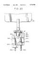
- FIG. 20shows another modified form which comprises two divided stoppers 60a and 60b.
- Each of the stoppers 60a and 60bis driven by a rotating rod 68a or 68b.
- One of the stoppers 68a or 68bis adapted to define one end of a range in which the stopped element 32 can be swung while the other stopper 68b or 68a is adapted to define the other end of such a range.
- the stopped element 32can be swung or oscillated from the neutral position in one and the other directions with different angles.
- the oscillation stopping areas 64a and 64bare arranged so that the roller 32a can be received by both of them.
- FIG. 21shows still another modified form which comprises an arm 82 supporting the input board 120. At end of the arm 82 is provided a stopped element 86.
- the arm 82can be rotated about a rotating shaft 84.
- the rotating shaft 84is forced to return back to a given position through reaction generating means as in the previously described embodiment.
- the stopped element 86is located between a pair of stoppers 70 which restrict the oscillation of the stopped element 86.
- each of the stoppers 70is mounted on mounting portions 74 through a spring 72.
- each stopper 70can exert a reaction force larger than the reaction force provided by the rotating shaft 84 to the stopped element 86 within a width range W in which the corresponding spring 72 is elastically deformed. Therefore, an impact to the stopper 70 can be absorbed when the oscillation of the stopped element 86 is restricted.
- Each of the mounting portions 74is engaged with a screw formed on the corresponding rotating rod 78 driven by a motor 76. As the rotating rods 78 are rotated, the mounting portions 74 can be moved. When the spacing between the mounting portions 74 is increased of decreased, the oscillation area of the stopped element 86 can be increased of decreased. When the oscillation area is decreased to its minimum level, the stopped element 86 can be completely restricted to make the input board 120 immobile at the neutral position.
- the inventionis not limited to such a game machine, but may be similarly applied to any other simulator adapted to perform a snow board, skate board, surfing board or the like.
- the swinging memberhas been described as an input board which can be simultaneously swung by both the feet of the player, the invention can be similarly applied to two interlocking input boards which can be swung by the feet of the player through a parallel linkage.
- two input boardsmay be independently swung by the respective feet of the player while at the same time first and second elastic means may be provided to generate independent reactions to the respective input boards.
Landscapes
- Engineering & Computer Science (AREA)
- Multimedia (AREA)
- Human Computer Interaction (AREA)
- Theoretical Computer Science (AREA)
- Health & Medical Sciences (AREA)
- General Health & Medical Sciences (AREA)
- Physical Education & Sports Medicine (AREA)
- Toys (AREA)
Abstract
Description
Claims (20)
Priority Applications (1)
| Application Number | Priority Date | Filing Date | Title |
|---|---|---|---|
| US08/979,845US6022272A (en) | 1995-06-22 | 1997-11-26 | Sliding simulator and game apparatus using the same |
Applications Claiming Priority (2)
| Application Number | Priority Date | Filing Date | Title |
|---|---|---|---|
| JP7-180998 | 1995-06-22 | ||
| JP7180998AJP2774951B2 (en) | 1995-06-22 | 1995-06-22 | Simulator operation input device |
Related Child Applications (1)
| Application Number | Title | Priority Date | Filing Date |
|---|---|---|---|
| US08/979,845ContinuationUS6022272A (en) | 1995-06-22 | 1997-11-26 | Sliding simulator and game apparatus using the same |
Publications (1)
| Publication Number | Publication Date |
|---|---|
| US5713794Atrue US5713794A (en) | 1998-02-03 |
Family
ID=16092952
Family Applications (2)
| Application Number | Title | Priority Date | Filing Date |
|---|---|---|---|
| US08/665,289Expired - LifetimeUS5713794A (en) | 1995-06-22 | 1996-06-17 | Simulator controlling device |
| US08/979,845Expired - LifetimeUS6022272A (en) | 1995-06-22 | 1997-11-26 | Sliding simulator and game apparatus using the same |
Family Applications After (1)
| Application Number | Title | Priority Date | Filing Date |
|---|---|---|---|
| US08/979,845Expired - LifetimeUS6022272A (en) | 1995-06-22 | 1997-11-26 | Sliding simulator and game apparatus using the same |
Country Status (2)
| Country | Link |
|---|---|
| US (2) | US5713794A (en) |
| JP (1) | JP2774951B2 (en) |
Cited By (106)
| Publication number | Priority date | Publication date | Assignee | Title |
|---|---|---|---|---|
| USD396888S (en) | 1996-12-12 | 1998-08-11 | Konami Co., Ltd. | Game machine |
| USD402707S (en) | 1996-09-09 | 1998-12-15 | Sega Enterprises, Ltd. | Simulation ski game machine |
| US5902214A (en)* | 1996-08-08 | 1999-05-11 | Shiraito Tani | Walk simulation apparatus |
| USD411258S (en) | 1998-02-16 | 1999-06-22 | Konami Co., Ltd. | Game machine |
| US5947824A (en)* | 1996-11-14 | 1999-09-07 | Konami Co., Ltd. | Flight simulation game apparatus |
| US5951404A (en)* | 1996-02-20 | 1999-09-14 | Konami Co., Ltd. | Riding game machine |
| US5967897A (en)* | 1997-11-11 | 1999-10-19 | Namco, Ltd. | Game input device and game apparatus |
| US6022272A (en)* | 1995-06-22 | 2000-02-08 | Namco Ltd. | Sliding simulator and game apparatus using the same |
| USD421070S (en)* | 1997-02-05 | 2000-02-22 | Atari Games Corporation | Electronic video game console |
| US6059666A (en)* | 1997-02-21 | 2000-05-09 | Namco Ltd. | Riding game system |
| US6120375A (en)* | 1997-02-28 | 2000-09-19 | Namco Ltd. | Pleasure ride device |
| USD431266S (en) | 1998-07-31 | 2000-09-26 | Sony Corporation | Game machine |
| US6132314A (en)* | 1997-05-23 | 2000-10-17 | Namco Limited | Operational input device for simulator |
| US6132313A (en)* | 1993-12-28 | 2000-10-17 | Konami Co., Ltd. | Manipulating device having three degree freedom |
| US6142870A (en)* | 1997-11-27 | 2000-11-07 | Konami Co., Ltd. | Simulation game machine |
| US6203426B1 (en)* | 1997-11-19 | 2001-03-20 | Konami Co., Ltd. | Character movement control in a competition video game |
| US6206702B1 (en) | 1999-08-24 | 2001-03-27 | Deborah A. Hayden | Methods and devices for treating unilateral neglect |
| US6270403B1 (en)* | 1996-09-11 | 2001-08-07 | Sega Enterprises, Ltd. | Ski simulator |
| USD446251S1 (en) | 1999-12-24 | 2001-08-07 | Konami Co., Ltd. | Game machine |
| US6296571B1 (en)* | 1999-03-02 | 2001-10-02 | Logitech Europe S.A. | Steering wheel spring assembly |
| US6368217B2 (en)* | 1997-02-14 | 2002-04-09 | Kabushiki Kaisha Sega Enterprises | Input device, data processing device, data processing method, game device and medium |
| US6543769B1 (en) | 1998-10-07 | 2003-04-08 | Slingshot Game Technology, Inc. | Snowboard apparatus |
| WO2003047704A1 (en)* | 2001-12-05 | 2003-06-12 | Mikhail Valentinovich Manuilov | Method for training mountain skiers and snowboarders (variants) and a device for carrying out said method |
| US6620043B1 (en)* | 2000-01-28 | 2003-09-16 | Disney Enterprises, Inc. | Virtual tug of war |
| US6685480B2 (en)* | 2000-03-24 | 2004-02-03 | Yamaha Corporation | Physical motion state evaluation apparatus |
| USD490118S1 (en) | 2003-06-12 | 2004-05-18 | Jeremiah Jackson, Sr. | Game station |
| US6743154B2 (en) | 2001-06-01 | 2004-06-01 | Neil B. Epstein | Omnidirectional moving surface |
| US20040110602A1 (en)* | 2002-12-04 | 2004-06-10 | Feldman Philip G. | Computer interactive isometric exercise system and method for operatively interconnecting the exercise system to a computer system for use as a peripheral |
| US20040127272A1 (en)* | 2001-04-23 | 2004-07-01 | Chan-Jong Park | System and method for virtual game |
| US6786850B2 (en) | 2000-10-04 | 2004-09-07 | Skatestrider Inc. | Exercise apparatus for simulating skating movement |
| US20040180719A1 (en)* | 2002-12-04 | 2004-09-16 | Philip Feldman | Game controller support structure and isometric exercise system and method of facilitating user exercise during game interaction |
| US20040198564A1 (en)* | 1998-12-17 | 2004-10-07 | Shigeo Takizawa | Lower limb function training device |
| US20040241631A1 (en)* | 2000-10-04 | 2004-12-02 | Nash Nizamuddin | Exercise apparatus for simulating skating movement |
| ES2232275A1 (en)* | 2002-10-28 | 2005-05-16 | Universidad Politecnica De Valencia | MOVEMENT CONTROL DEVICE IN REAL-TIME MOVEMENT SYNCHRONIZED TO THE TORSION MOVEMENTS OF A CENTRAL AXIS. |
| US20050209052A1 (en)* | 2000-02-02 | 2005-09-22 | Ashby Darren C | System and method for selective adjustment of exercise apparatus |
| USD510391S1 (en) | 2002-12-04 | 2005-10-04 | Powergrid Fitness, Inc. | Exercise device for controlling a video game |
| US20050227839A1 (en)* | 2004-04-03 | 2005-10-13 | Wu Chang Jy Richard | Compact stance guide and method of use |
| US20050239028A1 (en)* | 2004-04-03 | 2005-10-27 | Wu Chang J R | Stance guide and method of use |
| USD514627S1 (en)* | 2002-12-04 | 2006-02-07 | Powergrid Fitness, Inc. | Exercise system for controlling a video game |
| US20060063646A1 (en)* | 2004-09-20 | 2006-03-23 | Sven-Ake Sjostam | Play/athletic training appliance |
| US20060073941A1 (en)* | 2002-04-17 | 2006-04-06 | Perry Dynamics, Inc. | Proprioception machine |
| US7033176B2 (en) | 2002-07-17 | 2006-04-25 | Powergrid Fitness, Inc. | Motion platform system and method of rotating a motion platform about plural axes |
| US20060097453A1 (en)* | 2002-12-04 | 2006-05-11 | Philip Feldman | Game controller with force sensing input devices and method of measuring applied forces to game controller input devices to interact with a gaming application |
| USD527054S1 (en)* | 2004-05-12 | 2006-08-22 | Kevin Brase | Apparatus for a video game system |
| US20060205565A1 (en)* | 2002-12-04 | 2006-09-14 | Philip Feldman | Method and apparatus for operatively controlling a virtual reality scenario with a physically demanding interface |
| US20060217250A1 (en)* | 2005-03-10 | 2006-09-28 | Pearson Mike S | Board sport simulator and training device |
| US20060217243A1 (en)* | 2002-12-04 | 2006-09-28 | Philip Feldman | Isometric exercise system and method of facilitating user exercise during video game play |
| US20060223634A1 (en)* | 2005-04-04 | 2006-10-05 | Philip Feldman | Game controller connection system and method of selectively connecting a game controller with a plurality of different video gaming systems |
| US20060260395A1 (en)* | 2005-05-20 | 2006-11-23 | Philip Feldman | Force measurement system for an isometric exercise device |
| US20070078569A1 (en)* | 2005-09-30 | 2007-04-05 | Jeffrey Schox | Vehicle interface to communicate a safety alert mode command |
| US20070074922A1 (en)* | 2005-09-30 | 2007-04-05 | Coombs Joshua D | Vehicle interface based on a shift of the torso of a user |
| US20070074921A1 (en)* | 2005-09-30 | 2007-04-05 | Coombs Joshua D | Vehicle interface based on a shift of the appendages of a user |
| US20070078577A1 (en)* | 2005-09-30 | 2007-04-05 | Coombs Joshua D | Vehicle interface based on the weight distribution of a user |
| USD541875S1 (en)* | 2005-06-28 | 2007-05-01 | Sega Corporation | Game device |
| US20070155589A1 (en)* | 2002-12-04 | 2007-07-05 | Philip Feldman | Method and Apparatus for Operatively Controlling a Virtual Reality Scenario with an Isometric Exercise System |
| US20070155495A1 (en)* | 2005-12-19 | 2007-07-05 | Goo Paul E | Surf simulator platform / video game control unit and attitude sensor |
| US20070184953A1 (en)* | 2006-02-09 | 2007-08-09 | Sportkat, Llc | System and method of balance training |
| US20070265138A1 (en)* | 1999-07-08 | 2007-11-15 | Ashby Darren C | Methods and systems for controlling an exercise apparatus using a portable data storage device |
| US20080051256A1 (en)* | 1999-07-08 | 2008-02-28 | Icon Ip, Inc. | Exercise device with on board personal trainer |
| USD568408S1 (en)* | 2007-08-30 | 2008-05-06 | Kabushiki Kaisha Sega | Game device |
| USD569442S1 (en)* | 2007-08-30 | 2008-05-20 | Kabushiki Kaisha Sega | Game device |
| US20080146336A1 (en)* | 2002-12-04 | 2008-06-19 | Philip Feldman | Exercise Gaming Device and Method of Facilitating User Exercise During Video Game Play |
| US20080261696A1 (en)* | 2007-04-20 | 2008-10-23 | Nintendo Co., Ltd. | Game controller, storage medium storing game program, and game apparatus |
| US7465257B1 (en)* | 2004-09-13 | 2008-12-16 | Morgan Jr Robert Bowman | Cyber sports exercise system |
| US20090076686A1 (en)* | 2005-09-30 | 2009-03-19 | Jeffrey Schox | Vehicle interface to communicate a safety alert mode command |
| US20090094442A1 (en)* | 2007-10-05 | 2009-04-09 | Nintendo Co., Ltd | Storage medium storing load detecting program and load detecting apparatus |
| US20090093315A1 (en)* | 2007-10-04 | 2009-04-09 | Nintendo Co., Ltd. | Storage medium storing load detection program, load detection apparatus, and load detection method |
| USD597139S1 (en)* | 2008-09-26 | 2009-07-28 | Keyser Interactive, LLC | Interactive game kiosk with skateboard |
| USD597140S1 (en)* | 2008-09-26 | 2009-07-28 | Keyser Interactive, LLC | Interactive game kiosk with skateboard |
| USD598056S1 (en)* | 2008-09-26 | 2009-08-11 | Keyser Interactive, LLC | Interactive game kiosk |
| US20090258758A1 (en)* | 2001-10-19 | 2009-10-15 | Hickman Paul L | Mobile systems and methods for health, exercise and competition |
| US20090270226A1 (en)* | 1999-07-08 | 2009-10-29 | Watterson Scott R | Systems and methods for controlling the operation of one or more exercise devices and providing motivational programming |
| US20090270227A1 (en)* | 1999-07-08 | 2009-10-29 | Ashby Darren C | Systems, methods, and devices for simulating real world terrain on an exercise device |
| US7628730B1 (en) | 1999-07-08 | 2009-12-08 | Icon Ip, Inc. | Methods and systems for controlling an exercise apparatus using a USB compatible portable remote device |
| US7645213B2 (en) | 1999-07-08 | 2010-01-12 | Watterson Scott R | Systems for interaction with exercise device |
| US20100087239A1 (en)* | 2008-10-08 | 2010-04-08 | David Fisher | System for simulating river rafting and method thereof |
| USD615596S1 (en)* | 2008-03-20 | 2010-05-11 | Abitech Anna Bik | Foldable and adjustable multimedia stand for use in gaming to support a steering wheel and pedals |
| US7713171B1 (en) | 1995-12-14 | 2010-05-11 | Icon Ip, Inc. | Exercise equipment with removable digital script memory |
| US20100137063A1 (en)* | 2008-11-28 | 2010-06-03 | Mari Shirakawa | Information processing apparatus and computer readable storage medium |
| US20100169110A1 (en)* | 2008-12-26 | 2010-07-01 | Takao Sawano | Biological information management system |
| US20100216551A1 (en)* | 2009-02-20 | 2010-08-26 | Patrick Dwyer | Video game and peripheral for same |
| US20100224420A1 (en)* | 2009-03-09 | 2010-09-09 | Makoto Miyanaga | Computer readable storage medium storing information processing program and information processing apparatus |
| US20100245236A1 (en)* | 2009-03-30 | 2010-09-30 | Nintendo Co., Ltd. | Computer-readable storage medium and information processing apparatus |
| US20100248900A1 (en)* | 2009-03-27 | 2010-09-30 | Ashby Darren C | Exercise systems for simulating real world terrain |
| US20100265173A1 (en)* | 2009-04-20 | 2010-10-21 | Nintendo Co., Ltd. | Information processing program and information processing apparatus |
| US20110077088A1 (en)* | 2009-09-29 | 2011-03-31 | Nintendo Co., Ltd. | Computer-readable storage medium having stored information processing program thereon, and information processing apparatus |
| US20110077899A1 (en)* | 2009-09-28 | 2011-03-31 | Nintendo Co., Ltd. | Computer-readable storage medium having information processing program stored therein and information processing apparatus |
| US20110124387A1 (en)* | 2009-11-24 | 2011-05-26 | Sauerbrei Peter J | Video game and peripheral for same |
| USD650446S1 (en)* | 2010-12-16 | 2011-12-13 | Lockheed Martin Corporation | Modular flight deck simulator |
| US8387437B2 (en) | 2007-10-31 | 2013-03-05 | Nintendo Co., Ltd. | Weight applying unit for calibration and weight applying method for calibration |
| US8503086B2 (en) | 1995-11-06 | 2013-08-06 | Impulse Technology Ltd. | System and method for tracking and assessing movement skills in multidimensional space |
| US8654073B2 (en) | 2009-09-30 | 2014-02-18 | Nintendo Co., Ltd. | Information processing program having computer-readable storage medium therein and information processing apparatus |
| US20140243162A1 (en)* | 2011-08-02 | 2014-08-28 | Piotr Smolka | Ski simulator or snowboard simulator, set for games or for training comprising the simulator and a method of training with its usage |
| US9421456B2 (en) | 2007-10-09 | 2016-08-23 | Nintendo Co., Ltd. | Storage medium storing a load detecting program and load detecting apparatus |
| RU2640439C1 (en)* | 2017-03-24 | 2018-01-09 | Василий Юльевич Жиркевич | Method of imitation of displacement in virtual reality |
| US10188890B2 (en) | 2013-12-26 | 2019-01-29 | Icon Health & Fitness, Inc. | Magnetic resistance mechanism in a cable machine |
| US10220259B2 (en) | 2012-01-05 | 2019-03-05 | Icon Health & Fitness, Inc. | System and method for controlling an exercise device |
| US10226396B2 (en) | 2014-06-20 | 2019-03-12 | Icon Health & Fitness, Inc. | Post workout massage device |
| US10272317B2 (en) | 2016-03-18 | 2019-04-30 | Icon Health & Fitness, Inc. | Lighted pace feature in a treadmill |
| US10279212B2 (en) | 2013-03-14 | 2019-05-07 | Icon Health & Fitness, Inc. | Strength training apparatus with flywheel and related methods |
| US10391361B2 (en) | 2015-02-27 | 2019-08-27 | Icon Health & Fitness, Inc. | Simulating real-world terrain on an exercise device |
| US10426989B2 (en) | 2014-06-09 | 2019-10-01 | Icon Health & Fitness, Inc. | Cable system incorporated into a treadmill |
| US10433612B2 (en) | 2014-03-10 | 2019-10-08 | Icon Health & Fitness, Inc. | Pressure sensor to quantify work |
| US10493349B2 (en) | 2016-03-18 | 2019-12-03 | Icon Health & Fitness, Inc. | Display on exercise device |
| US10625137B2 (en) | 2016-03-18 | 2020-04-21 | Icon Health & Fitness, Inc. | Coordinated displays in an exercise device |
| US10671705B2 (en) | 2016-09-28 | 2020-06-02 | Icon Health & Fitness, Inc. | Customizing recipe recommendations |
Families Citing this family (11)
| Publication number | Priority date | Publication date | Assignee | Title |
|---|---|---|---|---|
| JP3618486B2 (en)* | 1996-09-11 | 2005-02-09 | 株式会社ナムコ | Simulator operation input device and simulator using the same |
| AT501409B1 (en)* | 1997-11-18 | 2008-10-15 | Heinrich Ketter | DEVICE FOR LEARNING THE PARALLEL KILAUF |
| US6592377B2 (en) | 2001-10-12 | 2003-07-15 | Karl J. Bendele, Jr. | Snowboard teaching device |
| CA2546185A1 (en)* | 2003-11-17 | 2005-05-26 | John Joseph Maccarron | Simulator for board sports |
| DE602005026884D1 (en)* | 2004-05-21 | 2011-04-28 | Technogym Spa | exercise machine |
| US20060258458A1 (en)* | 2005-05-13 | 2006-11-16 | Addington David R | System and method for interfacing a simulation device with a gaming device |
| JP2009523575A (en)* | 2006-01-17 | 2009-06-25 | ディーエヌエー ディジタル メディア グループ | Skateboard simulator |
| JP5265159B2 (en)* | 2007-09-11 | 2013-08-14 | 株式会社バンダイナムコゲームス | Program and game device |
| US20100081548A1 (en)* | 2008-10-01 | 2010-04-01 | Lawrence Labedz | Exercise simulator and method for encouraging exercise |
| USD609754S1 (en) | 2008-11-07 | 2010-02-09 | Keyser Interactive, LLC | Interactive game kiosk |
| USD597142S1 (en) | 2008-11-07 | 2009-07-28 | Keyser Interactive, LLC | Interactive game kiosk |
Citations (7)
| Publication number | Priority date | Publication date | Assignee | Title |
|---|---|---|---|---|
| US3159400A (en)* | 1961-12-06 | 1964-12-01 | Orbicon Ltd | Game apparatus for simulating skiing |
| US3408067A (en)* | 1966-05-19 | 1968-10-29 | Raymond E. Armstrong | Sking simulator device |
| US4629181A (en)* | 1983-07-21 | 1986-12-16 | Krive Irwin M | Multi-directional movement leg exerciser |
| US4817950A (en)* | 1987-05-08 | 1989-04-04 | Goo Paul E | Video game control unit and attitude sensor |
| US4869496A (en)* | 1987-06-18 | 1989-09-26 | Ottavio Colombo | Equipment for ski movement simulation |
| US4906192A (en)* | 1986-12-18 | 1990-03-06 | Smithard Michael A | Electronic computerized simulator apparatus |
| US5049079A (en)* | 1988-12-19 | 1991-09-17 | John H. Peterson | Closed loop ski simulation and instructional system |
Family Cites Families (3)
| Publication number | Priority date | Publication date | Assignee | Title |
|---|---|---|---|---|
| US5192258A (en)* | 1990-10-26 | 1993-03-09 | Martin Keller | Training device especially adapted for teaching snow boarding techniques |
| US5429562A (en)* | 1994-03-31 | 1995-07-04 | Surftek International Inc. | Mechanical surfing apparatus |
| JP2774951B2 (en)* | 1995-06-22 | 1998-07-09 | 株式会社ナムコ | Simulator operation input device |
- 1995
- 1995-06-22JPJP7180998Apatent/JP2774951B2/ennot_activeExpired - Fee Related
- 1996
- 1996-06-17USUS08/665,289patent/US5713794A/ennot_activeExpired - Lifetime
- 1997
- 1997-11-26USUS08/979,845patent/US6022272A/ennot_activeExpired - Lifetime
Patent Citations (7)
| Publication number | Priority date | Publication date | Assignee | Title |
|---|---|---|---|---|
| US3159400A (en)* | 1961-12-06 | 1964-12-01 | Orbicon Ltd | Game apparatus for simulating skiing |
| US3408067A (en)* | 1966-05-19 | 1968-10-29 | Raymond E. Armstrong | Sking simulator device |
| US4629181A (en)* | 1983-07-21 | 1986-12-16 | Krive Irwin M | Multi-directional movement leg exerciser |
| US4906192A (en)* | 1986-12-18 | 1990-03-06 | Smithard Michael A | Electronic computerized simulator apparatus |
| US4817950A (en)* | 1987-05-08 | 1989-04-04 | Goo Paul E | Video game control unit and attitude sensor |
| US4869496A (en)* | 1987-06-18 | 1989-09-26 | Ottavio Colombo | Equipment for ski movement simulation |
| US5049079A (en)* | 1988-12-19 | 1991-09-17 | John H. Peterson | Closed loop ski simulation and instructional system |
Cited By (169)
| Publication number | Priority date | Publication date | Assignee | Title |
|---|---|---|---|---|
| US6132313A (en)* | 1993-12-28 | 2000-10-17 | Konami Co., Ltd. | Manipulating device having three degree freedom |
| US6022272A (en)* | 1995-06-22 | 2000-02-08 | Namco Ltd. | Sliding simulator and game apparatus using the same |
| US8503086B2 (en) | 1995-11-06 | 2013-08-06 | Impulse Technology Ltd. | System and method for tracking and assessing movement skills in multidimensional space |
| US8861091B2 (en) | 1995-11-06 | 2014-10-14 | Impulse Technology Ltd. | System and method for tracking and assessing movement skills in multidimensional space |
| US8298123B2 (en) | 1995-12-14 | 2012-10-30 | Icon Health & Fitness, Inc. | Method and apparatus for remote interactive exercise and health equipment |
| US7713171B1 (en) | 1995-12-14 | 2010-05-11 | Icon Ip, Inc. | Exercise equipment with removable digital script memory |
| US7980996B2 (en) | 1995-12-14 | 2011-07-19 | Icon Ip, Inc. | Method and apparatus for remote interactive exercise and health equipment |
| US20100255955A1 (en)* | 1995-12-14 | 2010-10-07 | Hickman Paul L | Method and apparatus for remote interactive exercise and health equipment |
| US5951404A (en)* | 1996-02-20 | 1999-09-14 | Konami Co., Ltd. | Riding game machine |
| US5902214A (en)* | 1996-08-08 | 1999-05-11 | Shiraito Tani | Walk simulation apparatus |
| USD402707S (en) | 1996-09-09 | 1998-12-15 | Sega Enterprises, Ltd. | Simulation ski game machine |
| US6270403B1 (en)* | 1996-09-11 | 2001-08-07 | Sega Enterprises, Ltd. | Ski simulator |
| US5947824A (en)* | 1996-11-14 | 1999-09-07 | Konami Co., Ltd. | Flight simulation game apparatus |
| USD396888S (en) | 1996-12-12 | 1998-08-11 | Konami Co., Ltd. | Game machine |
| USD421070S (en)* | 1997-02-05 | 2000-02-22 | Atari Games Corporation | Electronic video game console |
| US6739974B2 (en)* | 1997-02-14 | 2004-05-25 | Kabushiki Kaisha Sega Enterprises | Input device, data processing device, data processing method, game device and medium |
| US6368217B2 (en)* | 1997-02-14 | 2002-04-09 | Kabushiki Kaisha Sega Enterprises | Input device, data processing device, data processing method, game device and medium |
| US20020094867A1 (en)* | 1997-02-14 | 2002-07-18 | Kabushiki Kaisha Sega Enterprises | Input device, data processing device, data processing method, game device and medium |
| US6059666A (en)* | 1997-02-21 | 2000-05-09 | Namco Ltd. | Riding game system |
| US6210286B1 (en) | 1997-02-21 | 2001-04-03 | Namco, Ltd. | Riding game system |
| US6120375A (en)* | 1997-02-28 | 2000-09-19 | Namco Ltd. | Pleasure ride device |
| US6132314A (en)* | 1997-05-23 | 2000-10-17 | Namco Limited | Operational input device for simulator |
| US5967897A (en)* | 1997-11-11 | 1999-10-19 | Namco, Ltd. | Game input device and game apparatus |
| US6203426B1 (en)* | 1997-11-19 | 2001-03-20 | Konami Co., Ltd. | Character movement control in a competition video game |
| US6471584B1 (en)* | 1997-11-27 | 2002-10-29 | Konami Co., Ltd. | Simulation game machine |
| EP0919267A3 (en)* | 1997-11-27 | 2001-04-18 | Konami Co., Ltd. | Simulation game machine |
| US6142870A (en)* | 1997-11-27 | 2000-11-07 | Konami Co., Ltd. | Simulation game machine |
| USD411258S (en) | 1998-02-16 | 1999-06-22 | Konami Co., Ltd. | Game machine |
| USD431266S (en) | 1998-07-31 | 2000-09-26 | Sony Corporation | Game machine |
| US6543769B1 (en) | 1998-10-07 | 2003-04-08 | Slingshot Game Technology, Inc. | Snowboard apparatus |
| US7481739B2 (en)* | 1998-12-17 | 2009-01-27 | Biophilia Institute Inc. | Lower limb function training device |
| US7322904B2 (en)* | 1998-12-17 | 2008-01-29 | Shigeo Takizawa | Lower limb function training device |
| US20040210168A1 (en)* | 1998-12-17 | 2004-10-21 | Shigeo Takizawa | Lower limb function training device |
| US20040198564A1 (en)* | 1998-12-17 | 2004-10-07 | Shigeo Takizawa | Lower limb function training device |
| US6296571B1 (en)* | 1999-03-02 | 2001-10-02 | Logitech Europe S.A. | Steering wheel spring assembly |
| US9028368B2 (en) | 1999-07-08 | 2015-05-12 | Icon Health & Fitness, Inc. | Systems, methods, and devices for simulating real world terrain on an exercise device |
| US7981000B2 (en) | 1999-07-08 | 2011-07-19 | Icon Ip, Inc. | Systems for interaction with exercise device |
| US8758201B2 (en) | 1999-07-08 | 2014-06-24 | Icon Health & Fitness, Inc. | Portable physical activity sensing system |
| US8784270B2 (en) | 1999-07-08 | 2014-07-22 | Icon Ip, Inc. | Portable physical activity sensing system |
| US20070265138A1 (en)* | 1999-07-08 | 2007-11-15 | Ashby Darren C | Methods and systems for controlling an exercise apparatus using a portable data storage device |
| US7628730B1 (en) | 1999-07-08 | 2009-12-08 | Icon Ip, Inc. | Methods and systems for controlling an exercise apparatus using a USB compatible portable remote device |
| US8690735B2 (en) | 1999-07-08 | 2014-04-08 | Icon Health & Fitness, Inc. | Systems for interaction with exercise device |
| US20080051256A1 (en)* | 1999-07-08 | 2008-02-28 | Icon Ip, Inc. | Exercise device with on board personal trainer |
| US20090270227A1 (en)* | 1999-07-08 | 2009-10-29 | Ashby Darren C | Systems, methods, and devices for simulating real world terrain on an exercise device |
| US7645213B2 (en) | 1999-07-08 | 2010-01-12 | Watterson Scott R | Systems for interaction with exercise device |
| US7789800B1 (en) | 1999-07-08 | 2010-09-07 | Icon Ip, Inc. | Methods and systems for controlling an exercise apparatus using a USB compatible portable remote device |
| US8029415B2 (en) | 1999-07-08 | 2011-10-04 | Icon Ip, Inc. | Systems, methods, and devices for simulating real world terrain on an exercise device |
| US7985164B2 (en) | 1999-07-08 | 2011-07-26 | Icon Ip, Inc. | Methods and systems for controlling an exercise apparatus using a portable data storage device |
| US20090270226A1 (en)* | 1999-07-08 | 2009-10-29 | Watterson Scott R | Systems and methods for controlling the operation of one or more exercise devices and providing motivational programming |
| US7862478B2 (en) | 1999-07-08 | 2011-01-04 | Icon Ip, Inc. | System and methods for controlling the operation of one or more exercise devices and providing motivational programming |
| US6206702B1 (en) | 1999-08-24 | 2001-03-27 | Deborah A. Hayden | Methods and devices for treating unilateral neglect |
| USD446251S1 (en) | 1999-12-24 | 2001-08-07 | Konami Co., Ltd. | Game machine |
| US6620043B1 (en)* | 2000-01-28 | 2003-09-16 | Disney Enterprises, Inc. | Virtual tug of war |
| US20050209052A1 (en)* | 2000-02-02 | 2005-09-22 | Ashby Darren C | System and method for selective adjustment of exercise apparatus |
| US7645212B2 (en)* | 2000-02-02 | 2010-01-12 | Icon Ip, Inc. | System and method for selective adjustment of exercise apparatus |
| US6685480B2 (en)* | 2000-03-24 | 2004-02-03 | Yamaha Corporation | Physical motion state evaluation apparatus |
| US7556592B2 (en) | 2000-10-04 | 2009-07-07 | Technogym International B.V. | Method of using exercise apparatus for simulating skating movement |
| US20060287168A1 (en)* | 2000-10-04 | 2006-12-21 | Nash Nizam | Method of using exercise apparatus for simulating skating movement |
| US6786850B2 (en) | 2000-10-04 | 2004-09-07 | Skatestrider Inc. | Exercise apparatus for simulating skating movement |
| US20040241631A1 (en)* | 2000-10-04 | 2004-12-02 | Nash Nizamuddin | Exercise apparatus for simulating skating movement |
| US7115073B2 (en) | 2000-10-04 | 2006-10-03 | Skatestrider Inc. | Exercise apparatus for simulating skating movement |
| US20040127272A1 (en)* | 2001-04-23 | 2004-07-01 | Chan-Jong Park | System and method for virtual game |
| US6743154B2 (en) | 2001-06-01 | 2004-06-01 | Neil B. Epstein | Omnidirectional moving surface |
| US7857731B2 (en) | 2001-10-19 | 2010-12-28 | Icon Ip, Inc. | Mobile systems and methods for health, exercise and competition |
| US20090258758A1 (en)* | 2001-10-19 | 2009-10-15 | Hickman Paul L | Mobile systems and methods for health, exercise and competition |
| RU2233684C2 (en)* | 2001-12-05 | 2004-08-10 | Мануилов Михаил Валентинович | Method for exercising of mountain skiers and snowboarders (versions) and exercising apparatus |
| WO2003047704A1 (en)* | 2001-12-05 | 2003-06-12 | Mikhail Valentinovich Manuilov | Method for training mountain skiers and snowboarders (variants) and a device for carrying out said method |
| US20060073941A1 (en)* | 2002-04-17 | 2006-04-06 | Perry Dynamics, Inc. | Proprioception machine |
| US7465253B2 (en)* | 2002-04-17 | 2008-12-16 | Perry Dynamics, Inc. | Proprioception machine |
| US7033176B2 (en) | 2002-07-17 | 2006-04-25 | Powergrid Fitness, Inc. | Motion platform system and method of rotating a motion platform about plural axes |
| US7530929B2 (en) | 2002-07-17 | 2009-05-12 | Powergrid Fitness, Inc. | Motion platform system and method of rotating a motion platform about plural axes |
| ES2232253A1 (en)* | 2002-10-28 | 2005-05-16 | Universidad Politecnica De Valencia | Interactive, immersive interface and multiuser combination for controlling image in on time synchronous real movement of central wharf, has platform maintained by central wharf, and touch screen horizontally located within metallic railing |
| ES2232275A1 (en)* | 2002-10-28 | 2005-05-16 | Universidad Politecnica De Valencia | MOVEMENT CONTROL DEVICE IN REAL-TIME MOVEMENT SYNCHRONIZED TO THE TORSION MOVEMENTS OF A CENTRAL AXIS. |
| ES2232253B1 (en)* | 2002-10-28 | 2006-07-16 | Universidad Politecnica De Valencia | INTERACTIVE, IMMERSIVE AND MULTI-USER INTERFACE OF IMAGE CONTROL IN REAL TIME MOVEMENT SYNCHRONIZED TO THE TORSION MOVEMENTS OF A CENTRAL SPRING. |
| ES2232275B1 (en)* | 2002-10-28 | 2006-07-16 | Universidad Politecnica De Valencia | MOVEMENT CONTROL DEVICE IN REAL-TIME MOVEMENT SYNCHRONIZED TO THE TORSION MOVEMENTS OF A CENTRAL AXIS. |
| US20040180719A1 (en)* | 2002-12-04 | 2004-09-16 | Philip Feldman | Game controller support structure and isometric exercise system and method of facilitating user exercise during game interaction |
| USD517124S1 (en)* | 2002-12-04 | 2006-03-14 | Powergrid Fitness, Inc. | Game controller |
| US20070298883A1 (en)* | 2002-12-04 | 2007-12-27 | Philip Feldman | Method and Apparatus for Operatively Controlling a Virtual Reality Scenario in Accordance With Physical Activity of a User |
| US20050130742A1 (en)* | 2002-12-04 | 2005-06-16 | Philip Feldman | Configurable game controller and method of selectively assigning game functions to controller input devices |
| USD510391S1 (en) | 2002-12-04 | 2005-10-04 | Powergrid Fitness, Inc. | Exercise device for controlling a video game |
| USD514627S1 (en)* | 2002-12-04 | 2006-02-07 | Powergrid Fitness, Inc. | Exercise system for controlling a video game |
| US20080146336A1 (en)* | 2002-12-04 | 2008-06-19 | Philip Feldman | Exercise Gaming Device and Method of Facilitating User Exercise During Video Game Play |
| US7121982B2 (en) | 2002-12-04 | 2006-10-17 | Powergrid Fitness, Inc. | Computer interactive isometric exercise system and method for operatively interconnecting the exercise system to a computer system for use as a peripheral |
| US20060097453A1 (en)* | 2002-12-04 | 2006-05-11 | Philip Feldman | Game controller with force sensing input devices and method of measuring applied forces to game controller input devices to interact with a gaming application |
| US20070155589A1 (en)* | 2002-12-04 | 2007-07-05 | Philip Feldman | Method and Apparatus for Operatively Controlling a Virtual Reality Scenario with an Isometric Exercise System |
| US20040110602A1 (en)* | 2002-12-04 | 2004-06-10 | Feldman Philip G. | Computer interactive isometric exercise system and method for operatively interconnecting the exercise system to a computer system for use as a peripheral |
| US7727117B2 (en) | 2002-12-04 | 2010-06-01 | Ialabs-Ca, Llc | Method and apparatus for operatively controlling a virtual reality scenario with a physically demanding interface |
| US7699755B2 (en) | 2002-12-04 | 2010-04-20 | Ialabs-Ca, Llc | Isometric exercise system and method of facilitating user exercise during video game play |
| US20060205565A1 (en)* | 2002-12-04 | 2006-09-14 | Philip Feldman | Method and apparatus for operatively controlling a virtual reality scenario with a physically demanding interface |
| US20060217243A1 (en)* | 2002-12-04 | 2006-09-28 | Philip Feldman | Isometric exercise system and method of facilitating user exercise during video game play |
| USD493843S1 (en) | 2003-06-12 | 2004-08-03 | Jeremiah Jackson, Sr. | Game station |
| USD490118S1 (en) | 2003-06-12 | 2004-05-18 | Jeremiah Jackson, Sr. | Game station |
| US20050227839A1 (en)* | 2004-04-03 | 2005-10-13 | Wu Chang Jy Richard | Compact stance guide and method of use |
| US20050239028A1 (en)* | 2004-04-03 | 2005-10-27 | Wu Chang J R | Stance guide and method of use |
| USD527054S1 (en)* | 2004-05-12 | 2006-08-22 | Kevin Brase | Apparatus for a video game system |
| USD544923S1 (en) | 2004-05-12 | 2007-06-19 | Radica Games, Ltd. | Apparatus for a video game system |
| US7465257B1 (en)* | 2004-09-13 | 2008-12-16 | Morgan Jr Robert Bowman | Cyber sports exercise system |
| US20060063646A1 (en)* | 2004-09-20 | 2006-03-23 | Sven-Ake Sjostam | Play/athletic training appliance |
| US7488177B2 (en) | 2005-03-10 | 2009-02-10 | Pearson Mike S | Board sport simulator and training device |
| US20060217250A1 (en)* | 2005-03-10 | 2006-09-28 | Pearson Mike S | Board sport simulator and training device |
| US20060223634A1 (en)* | 2005-04-04 | 2006-10-05 | Philip Feldman | Game controller connection system and method of selectively connecting a game controller with a plurality of different video gaming systems |
| US7331226B2 (en) | 2005-05-20 | 2008-02-19 | Powergrid Fitness, Inc. | Force measurement system for an isometric exercise device |
| US20060260395A1 (en)* | 2005-05-20 | 2006-11-23 | Philip Feldman | Force measurement system for an isometric exercise device |
| USD541875S1 (en)* | 2005-06-28 | 2007-05-01 | Sega Corporation | Game device |
| US20090076686A1 (en)* | 2005-09-30 | 2009-03-19 | Jeffrey Schox | Vehicle interface to communicate a safety alert mode command |
| US8099200B2 (en)* | 2005-09-30 | 2012-01-17 | Coombs Joshua D | Vehicle interface based on the weight distribution of a user |
| US20070078577A1 (en)* | 2005-09-30 | 2007-04-05 | Coombs Joshua D | Vehicle interface based on the weight distribution of a user |
| US20120101665A1 (en)* | 2005-09-30 | 2012-04-26 | Coombs Joshua D | Vehicle interface based on the weight distribution of a user |
| US8620494B2 (en)* | 2005-09-30 | 2013-12-31 | Joshua D. Coombs | Vehicle interface based on the weight distribution of a user |
| US20070078569A1 (en)* | 2005-09-30 | 2007-04-05 | Jeffrey Schox | Vehicle interface to communicate a safety alert mode command |
| US20070074921A1 (en)* | 2005-09-30 | 2007-04-05 | Coombs Joshua D | Vehicle interface based on a shift of the appendages of a user |
| US20070074922A1 (en)* | 2005-09-30 | 2007-04-05 | Coombs Joshua D | Vehicle interface based on a shift of the torso of a user |
| US20070155495A1 (en)* | 2005-12-19 | 2007-07-05 | Goo Paul E | Surf simulator platform / video game control unit and attitude sensor |
| US20070184953A1 (en)* | 2006-02-09 | 2007-08-09 | Sportkat, Llc | System and method of balance training |
| US9289680B2 (en) | 2007-04-20 | 2016-03-22 | Nintendo Co., Ltd. | Game controller, storage medium storing game program, and game apparatus |
| US8574080B2 (en) | 2007-04-20 | 2013-11-05 | Nintendo Co., Ltd. | Game controller, storage medium storing game program, and game apparatus |
| US8100770B2 (en) | 2007-04-20 | 2012-01-24 | Nintendo Co., Ltd. | Game controller, storage medium storing game program, and game apparatus |
| US8740705B2 (en) | 2007-04-20 | 2014-06-03 | Nintendo Co., Ltd. | Game controller, storage medium storing game program, and game apparatus |
| US20080261696A1 (en)* | 2007-04-20 | 2008-10-23 | Nintendo Co., Ltd. | Game controller, storage medium storing game program, and game apparatus |
| USD568408S1 (en)* | 2007-08-30 | 2008-05-06 | Kabushiki Kaisha Sega | Game device |
| USD569442S1 (en)* | 2007-08-30 | 2008-05-20 | Kabushiki Kaisha Sega | Game device |
| US20090093315A1 (en)* | 2007-10-04 | 2009-04-09 | Nintendo Co., Ltd. | Storage medium storing load detection program, load detection apparatus, and load detection method |
| US8905844B2 (en) | 2007-10-05 | 2014-12-09 | Nintendo Co., Ltd. | Storage medium storing load detecting program and load detecting apparatus |
| US20090094442A1 (en)* | 2007-10-05 | 2009-04-09 | Nintendo Co., Ltd | Storage medium storing load detecting program and load detecting apparatus |
| US9421456B2 (en) | 2007-10-09 | 2016-08-23 | Nintendo Co., Ltd. | Storage medium storing a load detecting program and load detecting apparatus |
| US10343058B2 (en) | 2007-10-09 | 2019-07-09 | Nintendo Co., Ltd. | Storage medium storing a load detecting program and load detecting apparatus |
| US8887547B2 (en) | 2007-10-31 | 2014-11-18 | Nintendo Co., Ltd. | Weight applying unit for calibration and weight applying method for calibration |
| US8387437B2 (en) | 2007-10-31 | 2013-03-05 | Nintendo Co., Ltd. | Weight applying unit for calibration and weight applying method for calibration |
| USD615596S1 (en)* | 2008-03-20 | 2010-05-11 | Abitech Anna Bik | Foldable and adjustable multimedia stand for use in gaming to support a steering wheel and pedals |
| USD598056S1 (en)* | 2008-09-26 | 2009-08-11 | Keyser Interactive, LLC | Interactive game kiosk |
| USD597140S1 (en)* | 2008-09-26 | 2009-07-28 | Keyser Interactive, LLC | Interactive game kiosk with skateboard |
| USD597139S1 (en)* | 2008-09-26 | 2009-07-28 | Keyser Interactive, LLC | Interactive game kiosk with skateboard |
| US20100087239A1 (en)* | 2008-10-08 | 2010-04-08 | David Fisher | System for simulating river rafting and method thereof |
| US8152640B2 (en) | 2008-11-28 | 2012-04-10 | Nintendo Co., Ltd. | Information processing apparatus and computer readable storage medium |
| US20100137063A1 (en)* | 2008-11-28 | 2010-06-03 | Mari Shirakawa | Information processing apparatus and computer readable storage medium |
| US8612247B2 (en) | 2008-12-26 | 2013-12-17 | Nintendo Co., Ltd. | Biological information management system |
| US20100169110A1 (en)* | 2008-12-26 | 2010-07-01 | Takao Sawano | Biological information management system |
| US8517835B2 (en) | 2009-02-20 | 2013-08-27 | Activision Publishing, Inc. | Video game and peripheral for same |
| US20100216551A1 (en)* | 2009-02-20 | 2010-08-26 | Patrick Dwyer | Video game and peripheral for same |
| US8079251B2 (en) | 2009-03-09 | 2011-12-20 | Nintendo Co., Ltd. | Computer readable storage medium storing information processing program and information processing apparatus |
| US8707768B2 (en) | 2009-03-09 | 2014-04-29 | Nintendo Co., Ltd. | Computer readable storage medium storing information processing program and information processing apparatus |
| US20100224420A1 (en)* | 2009-03-09 | 2010-09-09 | Makoto Miyanaga | Computer readable storage medium storing information processing program and information processing apparatus |
| US20100248900A1 (en)* | 2009-03-27 | 2010-09-30 | Ashby Darren C | Exercise systems for simulating real world terrain |
| US8251874B2 (en) | 2009-03-27 | 2012-08-28 | Icon Health & Fitness, Inc. | Exercise systems for simulating real world terrain |
| US8395582B2 (en) | 2009-03-30 | 2013-03-12 | Nintendo Co., Ltd. | Computer-readable storage medium and information processing apparatus |
| US20100245236A1 (en)* | 2009-03-30 | 2010-09-30 | Nintendo Co., Ltd. | Computer-readable storage medium and information processing apparatus |
| US20100265173A1 (en)* | 2009-04-20 | 2010-10-21 | Nintendo Co., Ltd. | Information processing program and information processing apparatus |
| US9480918B2 (en) | 2009-09-28 | 2016-11-01 | Nintendo Co., Ltd. | Computer-readable storage medium having information processing program stored therein and information processing apparatus |
| US20110077899A1 (en)* | 2009-09-28 | 2011-03-31 | Nintendo Co., Ltd. | Computer-readable storage medium having information processing program stored therein and information processing apparatus |
| US20110077088A1 (en)* | 2009-09-29 | 2011-03-31 | Nintendo Co., Ltd. | Computer-readable storage medium having stored information processing program thereon, and information processing apparatus |
| US8751179B2 (en) | 2009-09-29 | 2014-06-10 | Nintendo Co., Ltd. | Computer-readable storage medium having stored information processing program thereon, and information processing apparatus |
| US8654073B2 (en) | 2009-09-30 | 2014-02-18 | Nintendo Co., Ltd. | Information processing program having computer-readable storage medium therein and information processing apparatus |
| US20110124387A1 (en)* | 2009-11-24 | 2011-05-26 | Sauerbrei Peter J | Video game and peripheral for same |
| US9101831B2 (en) | 2009-11-24 | 2015-08-11 | Activision Publishing, Inc. | Video game and peripheral for same |
| USD650446S1 (en)* | 2010-12-16 | 2011-12-13 | Lockheed Martin Corporation | Modular flight deck simulator |
| US20140243162A1 (en)* | 2011-08-02 | 2014-08-28 | Piotr Smolka | Ski simulator or snowboard simulator, set for games or for training comprising the simulator and a method of training with its usage |
| US10220259B2 (en) | 2012-01-05 | 2019-03-05 | Icon Health & Fitness, Inc. | System and method for controlling an exercise device |
| US10279212B2 (en) | 2013-03-14 | 2019-05-07 | Icon Health & Fitness, Inc. | Strength training apparatus with flywheel and related methods |
| US10188890B2 (en) | 2013-12-26 | 2019-01-29 | Icon Health & Fitness, Inc. | Magnetic resistance mechanism in a cable machine |
| US10433612B2 (en) | 2014-03-10 | 2019-10-08 | Icon Health & Fitness, Inc. | Pressure sensor to quantify work |
| US10426989B2 (en) | 2014-06-09 | 2019-10-01 | Icon Health & Fitness, Inc. | Cable system incorporated into a treadmill |
| US10226396B2 (en) | 2014-06-20 | 2019-03-12 | Icon Health & Fitness, Inc. | Post workout massage device |
| US10391361B2 (en) | 2015-02-27 | 2019-08-27 | Icon Health & Fitness, Inc. | Simulating real-world terrain on an exercise device |
| US10272317B2 (en) | 2016-03-18 | 2019-04-30 | Icon Health & Fitness, Inc. | Lighted pace feature in a treadmill |
| US10493349B2 (en) | 2016-03-18 | 2019-12-03 | Icon Health & Fitness, Inc. | Display on exercise device |
| US10625137B2 (en) | 2016-03-18 | 2020-04-21 | Icon Health & Fitness, Inc. | Coordinated displays in an exercise device |
| US10671705B2 (en) | 2016-09-28 | 2020-06-02 | Icon Health & Fitness, Inc. | Customizing recipe recommendations |
| WO2018174751A1 (en)* | 2017-03-24 | 2018-09-27 | Василий Юльевич ЖИРКЕВИЧ | Method for imitating movements in virtual reality |
| RU2640439C1 (en)* | 2017-03-24 | 2018-01-09 | Василий Юльевич Жиркевич | Method of imitation of displacement in virtual reality |
Also Published As
| Publication number | Publication date |
|---|---|
| JPH09742A (en) | 1997-01-07 |
| US6022272A (en) | 2000-02-08 |
| JP2774951B2 (en) | 1998-07-09 |
Similar Documents
| Publication | Publication Date | Title |
|---|---|---|
| US5713794A (en) | Simulator controlling device | |
| JP3692683B2 (en) | Game device | |
| JP3836154B2 (en) | Ski simulation equipment | |
| JP3001038B2 (en) | Simulator | |
| US6024675A (en) | Data-using game system | |
| US6398647B1 (en) | Method for displaying a reproduced image of a game | |
| US8043158B2 (en) | Game device and image processing device | |
| JP3677924B2 (en) | Display method and control method of video game apparatus | |
| EP1228793B1 (en) | Game progress control program, computer-readable recording medium, game server and game progress control method | |
| US20010016511A1 (en) | Entertainment system, entertainment apparatus, recording medium, and program | |
| EP0923967B1 (en) | Video game apparatus, guide displaying method in video game, and computer readable recording medium recording therein a guide display program | |
| JP3479522B2 (en) | 3D image processing program, 3D image processing method and apparatus | |
| JP3527569B2 (en) | Game device operating method and game device | |
| US20030112233A1 (en) | Image display control method, apparatus thereof, recording media on which the image display control is recorded, and game device | |
| JP2846308B2 (en) | Simulator and game device using the same | |
| JP2001149642A (en) | Game device and afterimage display method for game device | |
| JPH10340040A (en) | Simulator and game device using the same | |
| JPH0970483A (en) | Game device | |
| JPH08280936A (en) | Game device | |
| JP2001162048A (en) | Sports game apparatus and sports game play control method | |
| JP2000237457A (en) | Video game equipment | |
| JP3426588B2 (en) | GAME DEVICE, GAME CONTROL METHOD, AND PROGRAM | |
| JP2010082341A (en) | Program, information storage medium, and game console | |
| JP2010086432A (en) | Program, information storage medium, and game machine | |
| HK1020895B (en) | Video game apparatus, guide displaying method in video game, and computer readable recording medium recording therein a guide display program |
Legal Events
| Date | Code | Title | Description |
|---|---|---|---|
| AS | Assignment | Owner name:NAMCO. LTD., JAPAN Free format text:ASSIGNMENT OF ASSIGNORS INTEREST;ASSIGNORS:SHIMOJIMA, HIDEKI;SANO, TAKASHI;ONODERA, MAMORU (HEIR FOR TARO ONODERA, DECEASED);AND OTHERS;REEL/FRAME:008115/0547 Effective date:19960722 Owner name:ONODERA, MAMORU, JAPAN Free format text:PROOF OF AUTHORITY;ASSIGNOR:ONODERA, TARO (DECEASED);REEL/FRAME:008125/0573 Effective date:19960705 | |
| STCF | Information on status: patent grant | Free format text:PATENTED CASE | |
| FEPP | Fee payment procedure | Free format text:PAYOR NUMBER ASSIGNED (ORIGINAL EVENT CODE: ASPN); ENTITY STATUS OF PATENT OWNER: LARGE ENTITY | |
| FPAY | Fee payment | Year of fee payment:4 | |
| FPAY | Fee payment | Year of fee payment:8 | |
| AS | Assignment | Owner name:NAMCO BANDAI GAMES INC.,JAPAN Free format text:CHANGE OF NAME;ASSIGNOR:NAMCO LIMITED/NAMCO LTD.;REEL/FRAME:017996/0786 Effective date:20060331 Owner name:NAMCO BANDAI GAMES INC., JAPAN Free format text:CHANGE OF NAME;ASSIGNOR:NAMCO LIMITED/NAMCO LTD.;REEL/FRAME:017996/0786 Effective date:20060331 | |
| AS | Assignment | Owner name:NAMCO BANDAI GAMES INC, JAPAN Free format text:CHANGE OF ADDRESS;ASSIGNOR:NAMCO BANDAI GAMES INC.;REEL/FRAME:019834/0562 Effective date:20070710 Owner name:NAMCO BANDAI GAMES INC,JAPAN Free format text:CHANGE OF ADDRESS;ASSIGNOR:NAMCO BANDAI GAMES INC.;REEL/FRAME:019834/0562 Effective date:20070710 | |
| AS | Assignment | Owner name:NAMCO BANDAI GAMES INC., JAPAN Free format text:CHANGE OF ADDRESS;ASSIGNOR:NAMCO BANDAI GAMES INC.;REEL/FRAME:020206/0292 Effective date:20070710 Owner name:NAMCO BANDAI GAMES INC.,JAPAN Free format text:CHANGE OF ADDRESS;ASSIGNOR:NAMCO BANDAI GAMES INC.;REEL/FRAME:020206/0292 Effective date:20070710 | |
| FPAY | Fee payment | Year of fee payment:12 | |
| AS | Assignment | Owner name:BANDAI NAMCO ENTERTAINMENT INC., JAPAN Free format text:CHANGE OF NAME;ASSIGNOR:NAMCO BANDAI GAMES INC.;REEL/FRAME:038104/0935 Effective date:20150401 |