US5713651A - Modular frame assembly for an equipment cabinet - Google Patents
Modular frame assembly for an equipment cabinetDownload PDFInfo
- Publication number
- US5713651A US5713651AUS08/607,472US60747296AUS5713651AUS 5713651 AUS5713651 AUS 5713651AUS 60747296 AUS60747296 AUS 60747296AUS 5713651 AUS5713651 AUS 5713651A
- Authority
- US
- United States
- Prior art keywords
- frame
- assembly
- tabs
- frame members
- substantially conical
- Prior art date
- Legal status (The legal status is an assumption and is not a legal conclusion. Google has not performed a legal analysis and makes no representation as to the accuracy of the status listed.)
- Expired - Lifetime
Links
- 230000013011matingEffects0.000description8
- 230000000712assemblyEffects0.000description6
- 238000000429assemblyMethods0.000description6
- 238000009423ventilationMethods0.000description3
- 238000004378air conditioningMethods0.000description2
- 238000010276constructionMethods0.000description2
- 239000006260foamSubstances0.000description2
- 238000010438heat treatmentMethods0.000description2
- 239000000463materialSubstances0.000description2
- 206010003402Arthropod stingDiseases0.000description1
- 229910001335Galvanized steelInorganic materials0.000description1
- 239000008397galvanized steelSubstances0.000description1
- 238000009434installationMethods0.000description1
- 239000007787solidSubstances0.000description1
- 238000003466weldingMethods0.000description1
Images


Classifications
- F—MECHANICAL ENGINEERING; LIGHTING; HEATING; WEAPONS; BLASTING
- F16—ENGINEERING ELEMENTS AND UNITS; GENERAL MEASURES FOR PRODUCING AND MAINTAINING EFFECTIVE FUNCTIONING OF MACHINES OR INSTALLATIONS; THERMAL INSULATION IN GENERAL
- F16B—DEVICES FOR FASTENING OR SECURING CONSTRUCTIONAL ELEMENTS OR MACHINE PARTS TOGETHER, e.g. NAILS, BOLTS, CIRCLIPS, CLAMPS, CLIPS OR WEDGES; JOINTS OR JOINTING
- F16B12/00—Jointing of furniture or the like, e.g. hidden from exterior
- F16B12/44—Leg joints; Corner joints
- F16B12/50—Metal corner connections
- F—MECHANICAL ENGINEERING; LIGHTING; HEATING; WEAPONS; BLASTING
- F24—HEATING; RANGES; VENTILATING
- F24F—AIR-CONDITIONING; AIR-HUMIDIFICATION; VENTILATION; USE OF AIR CURRENTS FOR SCREENING
- F24F13/00—Details common to, or for air-conditioning, air-humidification, ventilation or use of air currents for screening
- F24F13/20—Casings or covers
- H—ELECTRICITY
- H02—GENERATION; CONVERSION OR DISTRIBUTION OF ELECTRIC POWER
- H02B—BOARDS, SUBSTATIONS OR SWITCHING ARRANGEMENTS FOR THE SUPPLY OR DISTRIBUTION OF ELECTRIC POWER
- H02B1/00—Frameworks, boards, panels, desks, casings; Details of substations or switching arrangements
- H02B1/01—Frameworks
- H02B1/013—Profiles for cabinet frames
- H—ELECTRICITY
- H02—GENERATION; CONVERSION OR DISTRIBUTION OF ELECTRIC POWER
- H02B—BOARDS, SUBSTATIONS OR SWITCHING ARRANGEMENTS FOR THE SUPPLY OR DISTRIBUTION OF ELECTRIC POWER
- H02B1/00—Frameworks, boards, panels, desks, casings; Details of substations or switching arrangements
- H02B1/01—Frameworks
- H02B1/014—Corner connections for frameworks
- Y—GENERAL TAGGING OF NEW TECHNOLOGICAL DEVELOPMENTS; GENERAL TAGGING OF CROSS-SECTIONAL TECHNOLOGIES SPANNING OVER SEVERAL SECTIONS OF THE IPC; TECHNICAL SUBJECTS COVERED BY FORMER USPC CROSS-REFERENCE ART COLLECTIONS [XRACs] AND DIGESTS
- Y10—TECHNICAL SUBJECTS COVERED BY FORMER USPC
- Y10T—TECHNICAL SUBJECTS COVERED BY FORMER US CLASSIFICATION
- Y10T403/00—Joints and connections
- Y10T403/44—Three or more members connected at single locus
- Y10T403/447—Mutually contacting
- Y—GENERAL TAGGING OF NEW TECHNOLOGICAL DEVELOPMENTS; GENERAL TAGGING OF CROSS-SECTIONAL TECHNOLOGIES SPANNING OVER SEVERAL SECTIONS OF THE IPC; TECHNICAL SUBJECTS COVERED BY FORMER USPC CROSS-REFERENCE ART COLLECTIONS [XRACs] AND DIGESTS
- Y10—TECHNICAL SUBJECTS COVERED BY FORMER USPC
- Y10T—TECHNICAL SUBJECTS COVERED BY FORMER US CLASSIFICATION
- Y10T403/00—Joints and connections
- Y10T403/46—Rod end to transverse side of member
Definitions
- the present inventionis related to frame assemblies.
- the present inventionis a modular frame assembly for an equipment cabinet.
- Equipment cabinetsare not new. Nor are equipment cabinets having a plurality of frame members releasably secured together. Examples of known equipment cabinets are illustrated in U.S. Pat. No. 4,997,240 to Schmalzl, et al. and U.S. Pat. No. 4,040,694, to Lascarrou.
- the Schmalzl patentdiscloses a modular housing system having guide grooves having a keyhole shaped cross section and capping pieces at the ends. The capping pieces are connectable to one another via corner nodes that are provided with two pegs positioned diagonally opposite one another at three sides allocated to different corner plains.
- the Lascarrou patentdiscloses a cabinet and cubical formed by assembling framework members having at their ends cylindrical openings and conical cylindrical projections which are centered in the cylindrical openings and a screw inserted therein for retaining the framework.
- HVACheating, ventilation and air conditioning
- Moving equipment cabinets from one location to anothertypically requires complete disassembly of the equipment cabinet because the frame members of typical cabinets are usually very heavy. Additionally, typically if any pieces of the frame are removed, the other frame members no longer form easily moveable portions.
- the present inventionprovides a modular frame assembly for an equipment cabinet having a plurality of members releasably secured together. At least first, second and third frame members are provided, each of which have a securing tab and an offset securing tab projecting therefrom.
- the securing tabs of the frame membersmate with an offset securing tab of another frame member.
- the securing tab of the first frame membermates with the offset securing tab of the second frame member
- the securing tab of the second frame membermates with the offset securing tab of the third frame member
- the securing tab of the third frame membermates with the offset securing member of the first frame member.
- a receiving cavityis formed in each of the tabs and a plurality of fasteners are provided which are insertable into the receiving cavities to releasably secure the first, second and third frame members together.
- Thisprovides a modular frame assembly that allows disassembly of a single frame member by removing two of the fasteners at each corner. The third fastener remains in place and maintains the integrity of the remaining two frame members.
- each frame memberis preferably a universal member which allows either end to mate with any two other ends.
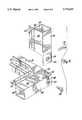
- FIG. 1is a perspective view of a plurality of modules joined together.
- FIG. 2is a perspective view of a single modular frame assembly according to the present invention.
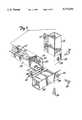
- FIG. 3is a perspective view of an individual frame member according to the present invention.
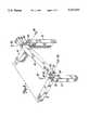
- FIG. 4is an enlarged perspective view of a corner of the modular frame assembly of FIG. 2.
- FIG. 5is an inside perspective view of a corner from a modular frame assembly according to the present invention.
- FIG. 6is a partially exploded perspective view of the corner of FIG 5.
- FIG. 7is a fully exploded perspective view of the corner of FIG. 5.
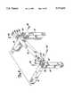
- FIG. 8is a partially exploded perspective view of a third frame member being joined to a first and second frame member which are already secured together.
- FIG. 9is a cross-sectional view taken along line 9--9 of FIG. 4.
- FIG. 10is a sectional view taken along line 10--10 from FIG. 1.
- FIG. 1is a perspective view of a heating, ventilation and air conditioning (HVAC) unit 20.
- Unit 20is comprised of a number of individual modular frame assemblies 22 for housing individual components.
- Frame assemblies 22are comprised of a plurality of individual frame members 24 and frame panels 26.
- Solid frame panels 26may be replaced with ventilation grids 28 or access doors 30 as illustrated in FIG. 1 or other such enclosing member if desired.
- the present inventionis directed to a unique embodiment of frame members 24 to allow frame assemblies 22 to be releasably secured together such that an individual frame member 24 can be removed while other frame members in the assembly remain secured.
- FIG. 2is a perspective view of an individual frame 22 assembly, similar to those illustrated in FIG. 1.
- Frame assembly 22is comprised of twelve individual frame members 24 which are joined at eight corners 32 with three fasteners 34 at each corner.
- frame members 24are box channel frame members manufacturable in variable lengths so that frame assembly 22 may be constructed in a variety of heights, lengths and widths.
- the box channel constructioncan be seen in greater detail in FIGS. 4, 6, 7 and 10. It should be understood that other types of post or frame member constructions could also be used without departing from the spirit or scope of the present invention.
- FIG. 3is a perspective view of an individual frame member 24.
- frame members 24are preferably box channels having first, second, third and fourth sidewalls 36, 38, 40 and 42 respectively.
- Frame member 24is illustrated having a first end 44 and a second end 46.
- second end 46is formed to be the mirror image of first end 44 such that each frame member 24 is a universal piece.
- Frame member 24is preferably fabricated to be a universal part such that it may mate with two additional like parts to form a three axis corner which is square, rigid and strong.
- frame members 24are fabricated from 690 galvanized steel, but other such materials are also considered within the spirit and scope of the invention.
- the Figures and the remaining description of the present inventionare directed to universally formed frame members but it should be noted, however, that other embodiments of a universal frame member or non-universal frame members are also applicable to the present invention.
- first sidewall 36extends beyond third and fourth sidewalls 40, 42 to form a securing tab 48.
- second sidewall 38extends beyond the third and fourth sidewalls to form an offset securing tab 50.
- Second end 46also has a pair of securing tabs 48 and 50 extending from first and second sidewalls 36, 38, respectively.
- offset securing tab 50is an extension of first sidewall 36 and securing tab 48 is an extension of second sidewall 38.
- offset securing tab 50is offset inward towards the plane of fourth sidewall 42 and at second end 46 offset securing tab 50 is offset inward towards the plane of sidewall 40.
- Tabs 50are offset to allow them to mate with other non offset tabs as will be described in detail below.
- Securing tabs 48each have a receiving cavity 52 formed therein and offset securing tabs 50 each have a receiving cavity 54 formed therein.
- Receiving cavities 52, 54have mating cones 53, 55, respectively, surrounding them to allow a fastener to be mounted flush with securing tab 48 and to allow mating cone 53 to be seated in mating cone 55. This provides increased mechanical strength for the corner when frame members 24 are joined together. Additionally, mating cone 55 on offset tab 50 is extruded to provide additional engagement depth for fasteners 34.
- FIG. 9An example of how the mating cones of receiving cavities 52, 54 mate together is illustrated in FIG. 9.
- FIG. 4illustrates an enlarged perspective view of one of the corners from FIG. 2.
- FIG. 4is illustrated as having first, second and third frame members 56, 58, 60, respectively, secured together via fasteners 34.
- Each of first, second and third frame members 56, 58, and 60are manufactured like frame member 24 from FIG. 3, such that each of the frame members has a securing tab 56a, 58a and 60a, respectively, and an offset securing tab 56b, 58b and 60b.
- Offset securing tab 56bis hidden behind securing tab 60a
- offset securing tab 58bis hidden behind securing tab 56a
- offset securing tab 60bis hidden behind securing tab 58a.
- FIG. 5is a perspective view of another corner 32 of frame assembly 22.
- frame members 24have flanges 62 projecting from third and fourth sidewalls 40 and 42.
- Flanges 62can also be seen in FIGS. 6, 7, 8 and 10.
- Flanges 62may be formed as extensions of sidewalls 40, 42 as is illustrated clearly in FIG. 10, or they could be add on pieces that are welded to frame members 24.
- spot welds 64are provided as illustrated in FIG. 5 to give flanges 62 and frame members 24 additional strength.
- Flanges 62are provided for facilitating the mounting of frame panels 26 or otherwise such enclosing members.
- the flangesintersect at intersection 66 forming an inside corner for the frame assembly.
- Flanges 62have an alternating pattern of holes 68 and slots 70. This alternating pattern has a two fold purpose. Firstly, it reduces the heat transfer surface by providing less material area for heat flow exposure. Secondly, it provides a universal pattern for screws to hold panels 26 and other such enclosing members in place.
- FIG. 6is a partially exploded perspective view of the corner assembly depicted in FIG. 5.
- Two fasteners 34have been removed which allows one frame member 24 to be removed.
- the other two frame members 24remain secured.
- FIG. 7is a fully exploded perspective view of the corner assembly from FIG. 5. All three fasteners 34 have now been removed allowing all three frame members 24 freedom.
- FIG. 8illustrates a perspective view of a plurality of frame members 24 in various stages of assembly.
- Each of the frame membersis manufactured as described above with respect to FIG. 3.
- a pair of first and second frame members 72, 74 respectivelyare held together with a first fastener 78.
- Second and third fasteners 80, 82are provided to secure a third frame member 76 to first and second frame members 72, 74.
- First, second and third frame members 72, 74, and 76have securing tabs 83 and offset securing tabs 85, and receiving cavities 87 and 89, respectively, as described above with respect to FIG. 3.
- offset securing tabs 85 of third frame member 76are positioned inside of securing tabs 83 of first frame members 72 while securing tabs 83 of third frame member 76 are positioned outside of offset securing tabs 85 of second frame members 74.
- Second and third fasteners 80, 82are then inserted through receiving cavities 87 and 89 to secure the first, second and third frame members together.
- FIG. 9clearly illustrates how securing tabs 48 and offset securing tabs 50 mate together and how mating cones 53 and 55 mate together.
- Securing tabs 48 from a pair of frame membersare illustrated outside of offset securing tabs 50.
- Mating cone 53is illustrated nested with mating cone 55.
- Fasteners 34are illustrated inserted through receiving cavities 52, 54.
- fasteners 34are an undercut flat countersunk bolt having a 5/16 inch diameter and a minimum strip-out torque of 200 inch-pounds, however, other similar fastening means are also considered to be within the spirit and scope of the invention.
- FIG. 10is a top perspective view of two frame assemblies 90, 92 being positioned adjacent to each other.
- a first frame member 94is provided having first and second flanges 96, 98 projecting therefrom.
- a first panel member 100is provided and is secured to flange 98 with a fastener 102.
- a second frame member 104is provided having first and second flanges 106, 108 projecting therefrom.
- a second panel member 110is provided and is secured to flange 108 with a fastener 112.
- Gaskets 114are provided about the flanges of first and second frame members 94 and 104, respectively, as illustrated in FIG. 10. Gaskets 114 are provided to help prevent thermal bridging and to serve as an air seal around the perimeter of any panel members installed.
- the gaskets of the preferred embodimentare a foam gasket that is metered onto the flanges and then rises and cures to a finished gasket.
- Other types of gasketssuch as an extruded foam gasket can also be used without departing from the spirit or scope of the present invention.
- An insulated liner 116is provided for joining assembly modules together and forming an insulated and gasket seal.
- Insulated liner 116is illustrated attached to flange 106, and would also be attached to flange 96.
- Liner 116is sized such that when flange 96 is attached to liner 116, frame member 94 is abutting frame member 104. Insulated liner 116 helps guide individual frame assemblies together during installation and provides a substantially air tight joint to assure cabinet integrity.
Landscapes
- Engineering & Computer Science (AREA)
- General Engineering & Computer Science (AREA)
- Mechanical Engineering (AREA)
- Assembled Shelves (AREA)
- Patch Boards (AREA)
- Casings For Electric Apparatus (AREA)
Abstract
Description
Claims (22)
Priority Applications (5)
| Application Number | Priority Date | Filing Date | Title |
|---|---|---|---|
| US08/607,472US5713651A (en) | 1996-02-27 | 1996-02-27 | Modular frame assembly for an equipment cabinet |
| BR9707742-9ABR9707742A (en) | 1996-02-27 | 1997-02-12 | Modular structure assembly for an equipment cabinet. |
| CA002247845ACA2247845C (en) | 1996-02-27 | 1997-02-12 | Modular frame assembly for an equipment cabinet |
| AU20505/97AAU2050597A (en) | 1996-02-27 | 1997-02-12 | Modular frame assembly for an equipment cabinet |
| PCT/US1997/002201WO1997031556A1 (en) | 1996-02-27 | 1997-02-12 | Modular frame assembly for an equipment cabinet |
Applications Claiming Priority (1)
| Application Number | Priority Date | Filing Date | Title |
|---|---|---|---|
| US08/607,472US5713651A (en) | 1996-02-27 | 1996-02-27 | Modular frame assembly for an equipment cabinet |
Publications (1)
| Publication Number | Publication Date |
|---|---|
| US5713651Atrue US5713651A (en) | 1998-02-03 |
Family
ID=24432428
Family Applications (1)
| Application Number | Title | Priority Date | Filing Date |
|---|---|---|---|
| US08/607,472Expired - LifetimeUS5713651A (en) | 1996-02-27 | 1996-02-27 | Modular frame assembly for an equipment cabinet |
Country Status (4)
| Country | Link |
|---|---|
| US (1) | US5713651A (en) |
| AU (1) | AU2050597A (en) |
| BR (1) | BR9707742A (en) |
| WO (1) | WO1997031556A1 (en) |
Cited By (42)
| Publication number | Priority date | Publication date | Assignee | Title |
|---|---|---|---|---|
| US5938302A (en)* | 1995-09-22 | 1999-08-17 | Amco Engineering Co. | Multiple enclosures and method |
| US5997117A (en)* | 1997-06-06 | 1999-12-07 | Chatsworth Products, Inc. | Rack frame cabinet |
| US6070957A (en)* | 1997-03-25 | 2000-06-06 | Rittal-Werk Rudolf Loh Gmbh & Co. Kg | Device for fastening a support rail on frame legs and mounting panels of a switchgear cabinet |
| WO2001001533A1 (en)* | 1999-06-28 | 2001-01-04 | Cooper B-Line Limited | Frame structure for an enclosure for electrical equipment |
| US6260374B1 (en) | 2000-04-26 | 2001-07-17 | American Standard International Inc. | Easily installable field configurable air conditioning unit |
| US6481582B1 (en) | 2001-06-04 | 2002-11-19 | Cooper Technologies Company | Rack |
| US6530630B2 (en)* | 2001-07-13 | 2003-03-11 | Carrier Corporation | Panel seal for an air handling unit |
| US6681942B2 (en)* | 1999-10-27 | 2004-01-27 | Hewlett-Packard Development Company | Rack mount assembly |
| US6688712B2 (en)* | 2001-07-13 | 2004-02-10 | Carrier Corporation | Detachable frame for coil removal |
| US20040124319A1 (en)* | 2002-09-05 | 2004-07-01 | Armin Hofmann | System for connecting mounting rails |
| US20040177793A1 (en)* | 2003-03-12 | 2004-09-16 | Chun-Yi Lai | Structure table leg |
| US20040183409A1 (en)* | 2001-01-23 | 2004-09-23 | Cooper Technologies Company | Electrical equipment enclosure |
| US20050284081A1 (en)* | 2004-06-25 | 2005-12-29 | Porter William H | Building structure with purlin to beam connection |
| US20070170136A1 (en)* | 2006-01-25 | 2007-07-26 | Kenny Sean T | Modular outdoor kitchen systems |
| US20070210683A1 (en)* | 2006-03-13 | 2007-09-13 | Panduit Corp | Network Cabinet |
| US20070234666A1 (en)* | 2006-03-24 | 2007-10-11 | Porter William H | Integral connectors in tubular beams for building structures |
| US20070257585A1 (en)* | 2006-05-08 | 2007-11-08 | Kenny Sean T | Frame structure |
| US20090110471A1 (en)* | 2007-10-31 | 2009-04-30 | Montminy Jeffrey E | system of fasteners for attaching panels onto modules that are to be installed on an airplane ground support equipment cart |
| US20090123691A1 (en)* | 2004-11-16 | 2009-05-14 | Renault S.A.S | Metal sheet, method for fixing said metal sheet by flow drilling and assembly comprising same |
| USD598219S1 (en)* | 2007-02-26 | 2009-08-18 | Sparks Jr Douglas M | Support member system |
| US20090283488A1 (en)* | 2008-05-19 | 2009-11-19 | Chatsworth Products, Inc. | Seismically hardened two-post electronic equipment rack |
| US20110050052A1 (en)* | 2009-09-01 | 2011-03-03 | Emerson Network Power, Energy Systems, North America, Inc. | Telecommunications Enclosures |
| US20120062084A1 (en)* | 2010-09-10 | 2012-03-15 | Lewis Ii Richard Evans | Electronic equipment cabinet structure |
| US20120305534A1 (en)* | 2010-02-10 | 2012-12-06 | Williams Thomas David | Industrial Machine Assembly |
| US20130036702A1 (en)* | 2011-06-15 | 2013-02-14 | Selex Sistemi Integrati S.P.A. | Shelter |
| US20130208413A1 (en)* | 2012-02-10 | 2013-08-15 | Yi-Kuei Huang | Network attached storage device and assembling method thereof |
| ITMI20130052A1 (en)* | 2013-01-16 | 2014-07-17 | Privius S R L | STRUCTURE FOR CABINET CABINET |
| US8787023B2 (en) | 2010-09-10 | 2014-07-22 | Chatsworth Products, Inc. | Rail mounting clamp for electronic equipment enclosure |
| US9055677B2 (en) | 2010-09-10 | 2015-06-09 | Chatsworth Products, Inc. | Cable pass-through panel for electronic equipment enclosure |
| EP2905554A1 (en)* | 2014-02-11 | 2015-08-12 | VECAM-CO S.p.A. | Support member for a protection structure, kit comprising said support member, modular structure comprising said kit and method of assembling said modular structure |
| US20160051044A1 (en)* | 2014-08-25 | 2016-02-25 | Pro-Mart Industries, Inc. | Shelving brace |
| US9549482B2 (en) | 2014-09-05 | 2017-01-17 | Emerson Network Power, Energy Systems, North America, Inc. | Cabinet frame enclosures, frame members and corresponding methods |
| US20170191319A1 (en)* | 2016-01-06 | 2017-07-06 | Caterpillar Global Mining America Llc | Surface drill modular mast |
| US10077917B2 (en) | 2013-05-09 | 2018-09-18 | Carrier Corporation | Drain pan assembly for fan coil unit |
| US10274124B2 (en)* | 2014-09-19 | 2019-04-30 | Robert Bosch Gmbh | Framework assembly and hydraulic system having the same |
| US10299592B2 (en)* | 2015-03-15 | 2019-05-28 | Brian M. Goerges | Channel tube and tube nut framing apparatus |
| US10694845B2 (en)* | 2016-07-08 | 2020-06-30 | Mill Brothers Landscape & Nursery, Inc. | Grill insert enclosure |
| US11064803B2 (en)* | 2019-05-13 | 2021-07-20 | The West Retail Group Limited | Kit of parts for a kitchen unit |
| US20220257007A1 (en)* | 2021-02-16 | 2022-08-18 | Newage Products Inc. | Cabinet assembly |
| US11647833B2 (en) | 2020-09-16 | 2023-05-16 | Perfect Site LLC | Utility rack |
| US12268300B2 (en)* | 2020-09-08 | 2025-04-08 | Grillnetics LLC | Enclosure assembly system |
| WO2025160117A1 (en)* | 2024-01-22 | 2025-07-31 | United CoolAir, LLC | Patterned frame rail |
Citations (11)
| Publication number | Priority date | Publication date | Assignee | Title |
|---|---|---|---|---|
| CA642359A (en)* | 1962-06-05 | Elgin Metalformers Corporation | Equipment cabinet structure | |
| US3087768A (en)* | 1960-05-18 | 1963-04-30 | Amco Eng | Enclosure |
| US3305255A (en)* | 1964-08-27 | 1967-02-21 | Gen Electric | Structural framework corner |
| US3746417A (en)* | 1971-07-01 | 1973-07-17 | Gen Electric | Furniture system having means for connecting sub-assemblies thereof |
| US3832605A (en)* | 1973-05-01 | 1974-08-27 | Westinghouse Electric Corp | Prefabricated housing for electrical switchgear with external housing wall attachment means |
| US4040694A (en)* | 1974-12-12 | 1977-08-09 | La Telemecanique Electrique | Framework for metal cabinet |
| DE2659483A1 (en)* | 1976-12-30 | 1978-07-06 | Licentia Gmbh | Switch gear cabinet frame construction system - has frame profiles with recesses formed by re-entrant parts of hollow profiles side walls |
| US4257333A (en)* | 1979-01-26 | 1981-03-24 | Hyman Pollack | Shelving structure adapted for quick assembly and adjustment |
| US4665838A (en)* | 1985-09-26 | 1987-05-19 | Minshall Aubrey W | Shelving unit |
| US4997240A (en)* | 1989-03-28 | 1991-03-05 | Siemens Aktiengesellschaft | Modular housing system for electronic equipment |
| US5066161A (en)* | 1989-05-08 | 1991-11-19 | Pinney Richard C | Framework for cabinet structure |
- 1996
- 1996-02-27USUS08/607,472patent/US5713651A/ennot_activeExpired - Lifetime
- 1997
- 1997-02-12BRBR9707742-9Apatent/BR9707742A/ennot_activeApplication Discontinuation
- 1997-02-12WOPCT/US1997/002201patent/WO1997031556A1/enactiveApplication Filing
- 1997-02-12AUAU20505/97Apatent/AU2050597A/ennot_activeAbandoned
Patent Citations (11)
| Publication number | Priority date | Publication date | Assignee | Title |
|---|---|---|---|---|
| CA642359A (en)* | 1962-06-05 | Elgin Metalformers Corporation | Equipment cabinet structure | |
| US3087768A (en)* | 1960-05-18 | 1963-04-30 | Amco Eng | Enclosure |
| US3305255A (en)* | 1964-08-27 | 1967-02-21 | Gen Electric | Structural framework corner |
| US3746417A (en)* | 1971-07-01 | 1973-07-17 | Gen Electric | Furniture system having means for connecting sub-assemblies thereof |
| US3832605A (en)* | 1973-05-01 | 1974-08-27 | Westinghouse Electric Corp | Prefabricated housing for electrical switchgear with external housing wall attachment means |
| US4040694A (en)* | 1974-12-12 | 1977-08-09 | La Telemecanique Electrique | Framework for metal cabinet |
| DE2659483A1 (en)* | 1976-12-30 | 1978-07-06 | Licentia Gmbh | Switch gear cabinet frame construction system - has frame profiles with recesses formed by re-entrant parts of hollow profiles side walls |
| US4257333A (en)* | 1979-01-26 | 1981-03-24 | Hyman Pollack | Shelving structure adapted for quick assembly and adjustment |
| US4665838A (en)* | 1985-09-26 | 1987-05-19 | Minshall Aubrey W | Shelving unit |
| US4997240A (en)* | 1989-03-28 | 1991-03-05 | Siemens Aktiengesellschaft | Modular housing system for electronic equipment |
| US5066161A (en)* | 1989-05-08 | 1991-11-19 | Pinney Richard C | Framework for cabinet structure |
Cited By (74)
| Publication number | Priority date | Publication date | Assignee | Title |
|---|---|---|---|---|
| US5938302A (en)* | 1995-09-22 | 1999-08-17 | Amco Engineering Co. | Multiple enclosures and method |
| US6070957A (en)* | 1997-03-25 | 2000-06-06 | Rittal-Werk Rudolf Loh Gmbh & Co. Kg | Device for fastening a support rail on frame legs and mounting panels of a switchgear cabinet |
| US5997117A (en)* | 1997-06-06 | 1999-12-07 | Chatsworth Products, Inc. | Rack frame cabinet |
| GB2368469B (en)* | 1999-06-28 | 2003-11-26 | Cooper B Line Ltd | Frame structure for an enclosure for electrical equipment |
| WO2001001533A1 (en)* | 1999-06-28 | 2001-01-04 | Cooper B-Line Limited | Frame structure for an enclosure for electrical equipment |
| GB2368469A (en)* | 1999-06-28 | 2002-05-01 | Cooper B Line Ltd | Frame structure for an enclosure for electrical equipment |
| US6974037B2 (en) | 1999-10-27 | 2005-12-13 | Hewlett-Packard Development Company, L.P. | Rack mount assembly |
| US6681942B2 (en)* | 1999-10-27 | 2004-01-27 | Hewlett-Packard Development Company | Rack mount assembly |
| US20040020874A1 (en)* | 1999-10-27 | 2004-02-05 | Haney Gerome A. | Rack mount assembly |
| US6260374B1 (en) | 2000-04-26 | 2001-07-17 | American Standard International Inc. | Easily installable field configurable air conditioning unit |
| US20040183409A1 (en)* | 2001-01-23 | 2004-09-23 | Cooper Technologies Company | Electrical equipment enclosure |
| US6481582B1 (en) | 2001-06-04 | 2002-11-19 | Cooper Technologies Company | Rack |
| US6688712B2 (en)* | 2001-07-13 | 2004-02-10 | Carrier Corporation | Detachable frame for coil removal |
| US6530630B2 (en)* | 2001-07-13 | 2003-03-11 | Carrier Corporation | Panel seal for an air handling unit |
| US20040124319A1 (en)* | 2002-09-05 | 2004-07-01 | Armin Hofmann | System for connecting mounting rails |
| US6929227B2 (en)* | 2002-09-05 | 2005-08-16 | Hilti Aktiengesellschaft | System for connecting mounting rails |
| US20040177793A1 (en)* | 2003-03-12 | 2004-09-16 | Chun-Yi Lai | Structure table leg |
| US20050284081A1 (en)* | 2004-06-25 | 2005-12-29 | Porter William H | Building structure with purlin to beam connection |
| US20090123691A1 (en)* | 2004-11-16 | 2009-05-14 | Renault S.A.S | Metal sheet, method for fixing said metal sheet by flow drilling and assembly comprising same |
| US7976237B2 (en)* | 2004-11-16 | 2011-07-12 | Renault S.A.S. | Metal sheet, method for fixing said metal sheet by flow drilling and assembly comprising same |
| US20070170136A1 (en)* | 2006-01-25 | 2007-07-26 | Kenny Sean T | Modular outdoor kitchen systems |
| US20070210683A1 (en)* | 2006-03-13 | 2007-09-13 | Panduit Corp | Network Cabinet |
| US7718891B2 (en) | 2006-03-13 | 2010-05-18 | Panduit Corp. | Network cabinet |
| US20070234666A1 (en)* | 2006-03-24 | 2007-10-11 | Porter William H | Integral connectors in tubular beams for building structures |
| US20070257585A1 (en)* | 2006-05-08 | 2007-11-08 | Kenny Sean T | Frame structure |
| USD598219S1 (en)* | 2007-02-26 | 2009-08-18 | Sparks Jr Douglas M | Support member system |
| US20090110471A1 (en)* | 2007-10-31 | 2009-04-30 | Montminy Jeffrey E | system of fasteners for attaching panels onto modules that are to be installed on an airplane ground support equipment cart |
| US20090283488A1 (en)* | 2008-05-19 | 2009-11-19 | Chatsworth Products, Inc. | Seismically hardened two-post electronic equipment rack |
| US8424691B2 (en) | 2008-05-19 | 2013-04-23 | Chatsworth Products, Inc. | Seismically hardened two-post electronic equipment rack |
| US20110050052A1 (en)* | 2009-09-01 | 2011-03-03 | Emerson Network Power, Energy Systems, North America, Inc. | Telecommunications Enclosures |
| US8403431B2 (en) | 2009-09-01 | 2013-03-26 | Emerson Network Power, Energy Systems, North America, Inc. | Telecommunications enclosures |
| US20120305534A1 (en)* | 2010-02-10 | 2012-12-06 | Williams Thomas David | Industrial Machine Assembly |
| US10178784B2 (en) | 2010-09-10 | 2019-01-08 | Chatsworth Products, Inc. | Rail seal for electronic equipment enclosure |
| US11792948B2 (en) | 2010-09-10 | 2023-10-17 | Chatsworth Products, Inc. | Cable pass-through panel for electronic equipment enclosure |
| US10237994B2 (en) | 2010-09-10 | 2019-03-19 | Chatsworth Products, Inc. | Vertical mounting rail with cable management features |
| US20120062084A1 (en)* | 2010-09-10 | 2012-03-15 | Lewis Ii Richard Evans | Electronic equipment cabinet structure |
| US8787023B2 (en) | 2010-09-10 | 2014-07-22 | Chatsworth Products, Inc. | Rail mounting clamp for electronic equipment enclosure |
| US9980400B2 (en) | 2010-09-10 | 2018-05-22 | Chatsworth Products, Inc. | Rail seal for electronic equipment enclosure |
| US8901438B2 (en)* | 2010-09-10 | 2014-12-02 | Chatsworth Products, Inc. | Electronic equipment cabinet structure |
| US9055677B2 (en) | 2010-09-10 | 2015-06-09 | Chatsworth Products, Inc. | Cable pass-through panel for electronic equipment enclosure |
| US10653025B2 (en) | 2010-09-10 | 2020-05-12 | Chatsworth Products, Inc. | Cable pass-through panel for electronic equipment enclosure |
| US9814159B2 (en) | 2010-09-10 | 2017-11-07 | Chatsworth Products, Inc. | Rail seal for electronic equipment enclosure |
| US9408326B2 (en) | 2010-09-10 | 2016-08-02 | Chatsworth Products, Inc. | Electronic equipment cabinet structure |
| US9781852B2 (en) | 2010-09-10 | 2017-10-03 | Chatsworth Products, Inc. | Cable pass-through panel for electronic equipment enclosure |
| US12108553B2 (en) | 2010-09-10 | 2024-10-01 | Chatsworth Products, Inc. | Cable pass-through panel for electronic equipment enclosure |
| US10588227B2 (en) | 2010-09-10 | 2020-03-10 | Chatsworth Products, Inc. | Vertical mounting rail with cable management features |
| US11464123B2 (en) | 2010-09-10 | 2022-10-04 | Chatsworth Products, Inc. | Method of adapting an electronic equipment enclosure for cable management |
| US11039543B2 (en) | 2010-09-10 | 2021-06-15 | Chatsworth Products, Inc. | Vertical mounting rail with cable management features |
| US9642270B2 (en) | 2010-09-10 | 2017-05-02 | Chatsworth Products, Inc. | Rail seal for electronic equipment enclosure |
| US20130036702A1 (en)* | 2011-06-15 | 2013-02-14 | Selex Sistemi Integrati S.P.A. | Shelter |
| US20130208413A1 (en)* | 2012-02-10 | 2013-08-15 | Yi-Kuei Huang | Network attached storage device and assembling method thereof |
| US9622363B2 (en) | 2013-01-16 | 2017-04-11 | Privius S.R.L. | Structure for cabinet |
| WO2014111768A1 (en)* | 2013-01-16 | 2014-07-24 | Privius S.R.L. | Structure for cabinet |
| ITMI20130052A1 (en)* | 2013-01-16 | 2014-07-17 | Privius S R L | STRUCTURE FOR CABINET CABINET |
| US10077917B2 (en) | 2013-05-09 | 2018-09-18 | Carrier Corporation | Drain pan assembly for fan coil unit |
| EP2905554A1 (en)* | 2014-02-11 | 2015-08-12 | VECAM-CO S.p.A. | Support member for a protection structure, kit comprising said support member, modular structure comprising said kit and method of assembling said modular structure |
| US20160051044A1 (en)* | 2014-08-25 | 2016-02-25 | Pro-Mart Industries, Inc. | Shelving brace |
| US9549482B2 (en) | 2014-09-05 | 2017-01-17 | Emerson Network Power, Energy Systems, North America, Inc. | Cabinet frame enclosures, frame members and corresponding methods |
| US9622369B2 (en) | 2014-09-05 | 2017-04-11 | Emerson Network Power, Energy Systems, North America, Inc. | Cabinet frame enclosures, frame members and corresponding methods |
| US9578772B2 (en) | 2014-09-05 | 2017-02-21 | Emerson Network Power, Energy Systems, North America, Inc. | Cabinet frame enclosures, frame members and corresponding methods |
| US9596778B2 (en) | 2014-09-05 | 2017-03-14 | Emerson Network Power, Energy Systems, North America, Inc. | Cabinet frame enclosures, frame members and corresponding methods |
| US10274124B2 (en)* | 2014-09-19 | 2019-04-30 | Robert Bosch Gmbh | Framework assembly and hydraulic system having the same |
| US10299592B2 (en)* | 2015-03-15 | 2019-05-28 | Brian M. Goerges | Channel tube and tube nut framing apparatus |
| US20170191319A1 (en)* | 2016-01-06 | 2017-07-06 | Caterpillar Global Mining America Llc | Surface drill modular mast |
| US9945187B2 (en)* | 2016-01-06 | 2018-04-17 | Caterpillar Global Mining America Llc | Surface drill modular mast |
| US10694845B2 (en)* | 2016-07-08 | 2020-06-30 | Mill Brothers Landscape & Nursery, Inc. | Grill insert enclosure |
| US11064803B2 (en)* | 2019-05-13 | 2021-07-20 | The West Retail Group Limited | Kit of parts for a kitchen unit |
| US12268300B2 (en)* | 2020-09-08 | 2025-04-08 | Grillnetics LLC | Enclosure assembly system |
| US11647833B2 (en) | 2020-09-16 | 2023-05-16 | Perfect Site LLC | Utility rack |
| US20230276941A1 (en)* | 2020-09-16 | 2023-09-07 | Perfect Site LLC | Utility rack |
| US12144421B2 (en)* | 2020-09-16 | 2024-11-19 | Perfect Site LLC | Utility rack |
| US20220257007A1 (en)* | 2021-02-16 | 2022-08-18 | Newage Products Inc. | Cabinet assembly |
| US11647832B2 (en)* | 2021-02-16 | 2023-05-16 | Newage Products Inc. | Cabinet assembly |
| WO2025160117A1 (en)* | 2024-01-22 | 2025-07-31 | United CoolAir, LLC | Patterned frame rail |
Also Published As
| Publication number | Publication date |
|---|---|
| AU2050597A (en) | 1997-09-16 |
| BR9707742A (en) | 2000-01-04 |
| WO1997031556A1 (en) | 1997-09-04 |
Similar Documents
| Publication | Publication Date | Title |
|---|---|---|
| US5713651A (en) | Modular frame assembly for an equipment cabinet | |
| US5210984A (en) | Audiometric booth | |
| US4988008A (en) | Supporting framework for a control cabinet | |
| US4782637A (en) | Frame structure | |
| US6755004B1 (en) | Simple lap beam | |
| EP1053435B1 (en) | Insulation panel for cabinets containing air handling equipment | |
| US4643319A (en) | Framework for a switchboard cabinet | |
| US6965075B2 (en) | Frame for electrical and electronic equipment housing cabinets and a frame joining structure | |
| JP2007507862A (en) | Improvement of metal structures for manufacturing electrical cabinets / panels | |
| JPH07177939A (en) | Cabinet corner fittings and electrical cabinets containing the corner fittings | |
| US20030011289A1 (en) | Detachable frame for coil removal | |
| US5996828A (en) | Corner assembly for a box | |
| JPS63285308A (en) | Corner block for bonding square weight-shaped frame member | |
| EP0472793B1 (en) | Framework for cabinet structure | |
| KR100241800B1 (en) | Partition wall system provided with floating posts | |
| CA2247845C (en) | Modular frame assembly for an equipment cabinet | |
| US7987948B2 (en) | Length adjustable passenger handle assembly for elevator | |
| US4650263A (en) | Structural support and thin panel assembly | |
| JPH06299758A (en) | Method and device for mounting window frame | |
| GB2281326A (en) | Partitioning System | |
| GB2077879A (en) | Structural joint | |
| US11401722B1 (en) | Method and system for providing an improved wall structure for security cages | |
| US5235787A (en) | Method of constructing hexagonal structures | |
| US5829908A (en) | Joint assembly between structural members | |
| JPH065533Y2 (en) | Connection structure of cover for air conditioning pipe, inner joint member for lid, and inner joint member for cover |
Legal Events
| Date | Code | Title | Description |
|---|---|---|---|
| AS | Assignment | Owner name:AAF-MCQUAY INC., MINNESOTA Free format text:ASSIGNMENT OF ASSIGNORS INTEREST;ASSIGNORS:ESSIG, ROBERT A.;OLSEN, JAMES E.;LARSON, JAMES E.;REEL/FRAME:007890/0774 Effective date:19960227 | |
| STCF | Information on status: patent grant | Free format text:PATENTED CASE | |
| CC | Certificate of correction | ||
| AS | Assignment | Owner name:PNC BANK, NATIONAL ASSOICATIONS, AS AGENT, NEW JER Free format text:SECURITY AGREEMENT;ASSIGNOR:AAF-MCQUAY, INC.;REEL/FRAME:012841/0412 Effective date:19990930 | |
| FPAY | Fee payment | Year of fee payment:4 | |
| AS | Assignment | Owner name:BANK OF AMERICA, N.A., AS COLLATERAL AGENT, ILLINO Free format text:NOTICE OF GRANT OF SECURITY INTEREST;ASSIGNOR:AAF-MCQUAY, INC,;REEL/FRAME:013599/0342 Effective date:20021205 | |
| AS | Assignment | Owner name:AAF-MCQUAY INC., KENTUCKY Free format text:RELEASE OF SECURITY INTEREST;ASSIGNOR:PNC BANK, N.A. AS AGENT;REEL/FRAME:013669/0491 Effective date:20021205 | |
| FPAY | Fee payment | Year of fee payment:8 | |
| FPAY | Fee payment | Year of fee payment:12 |