US5713549A - Monitor support device - Google Patents
Monitor support deviceDownload PDFInfo
- Publication number
- US5713549A US5713549AUS08/445,710US44571095AUS5713549AUS 5713549 AUS5713549 AUS 5713549AUS 44571095 AUS44571095 AUS 44571095AUS 5713549 AUS5713549 AUS 5713549A
- Authority
- US
- United States
- Prior art keywords
- pivot
- base
- worm
- supporting
- pivotally coupled
- Prior art date
- Legal status (The legal status is an assumption and is not a legal conclusion. Google has not performed a legal analysis and makes no representation as to the accuracy of the status listed.)
- Expired - Fee Related
Links
- 238000010276constructionMethods0.000description1
Images
Classifications
- F—MECHANICAL ENGINEERING; LIGHTING; HEATING; WEAPONS; BLASTING
- F16—ENGINEERING ELEMENTS AND UNITS; GENERAL MEASURES FOR PRODUCING AND MAINTAINING EFFECTIVE FUNCTIONING OF MACHINES OR INSTALLATIONS; THERMAL INSULATION IN GENERAL
- F16M—FRAMES, CASINGS OR BEDS OF ENGINES, MACHINES OR APPARATUS, NOT SPECIFIC TO ENGINES, MACHINES OR APPARATUS PROVIDED FOR ELSEWHERE; STANDS; SUPPORTS
- F16M13/00—Other supports for positioning apparatus or articles; Means for steadying hand-held apparatus or articles
- F16M13/02—Other supports for positioning apparatus or articles; Means for steadying hand-held apparatus or articles for supporting on, or attaching to, an object, e.g. tree, gate, window-frame, cycle
- F16M13/022—Other supports for positioning apparatus or articles; Means for steadying hand-held apparatus or articles for supporting on, or attaching to, an object, e.g. tree, gate, window-frame, cycle repositionable
- F—MECHANICAL ENGINEERING; LIGHTING; HEATING; WEAPONS; BLASTING
- F16—ENGINEERING ELEMENTS AND UNITS; GENERAL MEASURES FOR PRODUCING AND MAINTAINING EFFECTIVE FUNCTIONING OF MACHINES OR INSTALLATIONS; THERMAL INSULATION IN GENERAL
- F16M—FRAMES, CASINGS OR BEDS OF ENGINES, MACHINES OR APPARATUS, NOT SPECIFIC TO ENGINES, MACHINES OR APPARATUS PROVIDED FOR ELSEWHERE; STANDS; SUPPORTS
- F16M11/00—Stands or trestles as supports for apparatus or articles placed thereon ; Stands for scientific apparatus such as gravitational force meters
- F16M11/02—Heads
- F16M11/18—Heads with mechanism for moving the apparatus relatively to the stand
- F—MECHANICAL ENGINEERING; LIGHTING; HEATING; WEAPONS; BLASTING
- F16—ENGINEERING ELEMENTS AND UNITS; GENERAL MEASURES FOR PRODUCING AND MAINTAINING EFFECTIVE FUNCTIONING OF MACHINES OR INSTALLATIONS; THERMAL INSULATION IN GENERAL
- F16M—FRAMES, CASINGS OR BEDS OF ENGINES, MACHINES OR APPARATUS, NOT SPECIFIC TO ENGINES, MACHINES OR APPARATUS PROVIDED FOR ELSEWHERE; STANDS; SUPPORTS
- F16M11/00—Stands or trestles as supports for apparatus or articles placed thereon ; Stands for scientific apparatus such as gravitational force meters
- F16M11/20—Undercarriages with or without wheels
- F16M11/2092—Undercarriages with or without wheels comprising means allowing depth adjustment, i.e. forward-backward translation of the head relatively to the undercarriage
- F—MECHANICAL ENGINEERING; LIGHTING; HEATING; WEAPONS; BLASTING
- F16—ENGINEERING ELEMENTS AND UNITS; GENERAL MEASURES FOR PRODUCING AND MAINTAINING EFFECTIVE FUNCTIONING OF MACHINES OR INSTALLATIONS; THERMAL INSULATION IN GENERAL
- F16M—FRAMES, CASINGS OR BEDS OF ENGINES, MACHINES OR APPARATUS, NOT SPECIFIC TO ENGINES, MACHINES OR APPARATUS PROVIDED FOR ELSEWHERE; STANDS; SUPPORTS
- F16M11/00—Stands or trestles as supports for apparatus or articles placed thereon ; Stands for scientific apparatus such as gravitational force meters
- F16M11/20—Undercarriages with or without wheels
- F16M11/24—Undercarriages with or without wheels changeable in height or length of legs, also for transport only, e.g. by means of tubes screwed into each other
- F—MECHANICAL ENGINEERING; LIGHTING; HEATING; WEAPONS; BLASTING
- F16—ENGINEERING ELEMENTS AND UNITS; GENERAL MEASURES FOR PRODUCING AND MAINTAINING EFFECTIVE FUNCTIONING OF MACHINES OR INSTALLATIONS; THERMAL INSULATION IN GENERAL
- F16M—FRAMES, CASINGS OR BEDS OF ENGINES, MACHINES OR APPARATUS, NOT SPECIFIC TO ENGINES, MACHINES OR APPARATUS PROVIDED FOR ELSEWHERE; STANDS; SUPPORTS
- F16M2200/00—Details of stands or supports
- F16M2200/02—Locking means
- F16M2200/021—Locking means for rotational movement
- F16M2200/024—Locking means for rotational movement by positive interaction, e.g. male-female connections
- F—MECHANICAL ENGINEERING; LIGHTING; HEATING; WEAPONS; BLASTING
- F16—ENGINEERING ELEMENTS AND UNITS; GENERAL MEASURES FOR PRODUCING AND MAINTAINING EFFECTIVE FUNCTIONING OF MACHINES OR INSTALLATIONS; THERMAL INSULATION IN GENERAL
- F16M—FRAMES, CASINGS OR BEDS OF ENGINES, MACHINES OR APPARATUS, NOT SPECIFIC TO ENGINES, MACHINES OR APPARATUS PROVIDED FOR ELSEWHERE; STANDS; SUPPORTS
- F16M2200/00—Details of stands or supports
- F16M2200/06—Arms
- F16M2200/063—Parallelogram arms
- Y—GENERAL TAGGING OF NEW TECHNOLOGICAL DEVELOPMENTS; GENERAL TAGGING OF CROSS-SECTIONAL TECHNOLOGIES SPANNING OVER SEVERAL SECTIONS OF THE IPC; TECHNICAL SUBJECTS COVERED BY FORMER USPC CROSS-REFERENCE ART COLLECTIONS [XRACs] AND DIGESTS
- Y10—TECHNICAL SUBJECTS COVERED BY FORMER USPC
- Y10S—TECHNICAL SUBJECTS COVERED BY FORMER USPC CROSS-REFERENCE ART COLLECTIONS [XRACs] AND DIGESTS
- Y10S248/00—Supports
- Y10S248/917—Video display screen support
- Y10S248/919—Adjustably orientable video screen support
Definitions
- the present inventionrelates to a support device, and more particularly to a support device for supporting monitors and the like.
- Typical monitorsare directly disposed on the computer or on the computer desk.
- the monitorsnormally include a heavy weight such that the monitors may not be easily moved to suitable position.
- the present inventionhas arisen to mitigate and/or obviate the afore-described disadvantages of the conventional monitors.
- the primary objective of the present inventionis to provide a support device for supporting a monitor thereon, in which the monitor may be easily moved and adjusted to suitable position.
- a support devicefor supporting an object thereon.
- the support devicecomprises a base including a wall means extended upward therefrom, the wall means including a pivot axle, a worm rotatably supported on the base and including means for rotating the worm, and a beam including a first end pivotally coupled to the wall means at the pivot axle and including a plurality of teeth formed on the first end thereof for engaging with the worm, the beam including a second end for supporting the object thereon.
- the beamis rotated about the pivot axle by the worm so as to move the object upward and downward.
- a bracketis pivotally coupled to the second end of the beam at a pivot shaft for supporting the object
- a leverincludes a first end pivotally coupled to the wall means at a pivot pin and includes a second end pivotally coupled to the bracket at a pivot axis, the pivot pin is arranged below the pivot axle, and the pivot axis is arranged below the pivot shaft.
- the pivot axle, the pivot shaft, the pivot axis and the pivot pinform a parallelogram.
- the baseis engaged on a clamping means for clamping onto a desk and rotatably supported on and secured to the clamping means by a fastening means such that the base is rotatable about the fastening means.
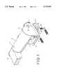
- FIG. 1is a perspective view of a monitor support device in accordance with the present invention.
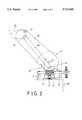
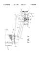
- FIGS. 2 and 3are schematic views illustrating the operation of the support device.
- a monitor support device in accordance with the present inventioncomprises a clamping mechanism 10 for clamping onto a support member, such as a desk, by fastening members 101.
- the clamping mechanism 10may also be a clip means, and is not related to the present invention and will not be described in further details.
- a base 12is disposed on the clamping mechanism and rotatably coupled to the clamping mechanism by a fastening member 11.
- the base 12includes a pair of walls 13 extended upward therefrom and includes a pair of plates 14 extended upward therefrom and located between the walls 13.
- a pair of studs 15are disposed in the middle portion of the base 12 for rotatably supporting a worm 16 thereon.
- the worm 16includes a knob 17 secured thereto and extended outward of the walls 13 for rotating the worm 16.
- a beam 20has a lower end pivotally coupled to the walls 13 at a pivot axle 21 and has a number of teeth 22 formed in the lower end for engaging with the worm 16 such that the beam 20 may be rotated by the worm 16 when the worm 16 is rotated by the knob 17.
- a bracket 30is pivotally coupled to the other end of the beam 20 at a pivot shaft 31 for supporting a monitor 90 (FIG. 3), a printer, a book or other objects thereon. The object supported on the beam 20 may be moved up and down when the beam 20 is rotated about the pivot axle 21 by the worm 16.
- a lever 40includes one end pivotally coupled to the plates 14 at a pivot pin 41 and the other end pivotally coupled to the bracket 30 at a pivot axis 42. It is preferable that a pair of levers 40 are coupled between the plates 14 and the bracket 30 so as to stably support the bracket 30 in place.
- the pivot pin 41may either be secured to the plates 14 or secured to the walls 13 and is located below the pivot axle 21.
- the pivot pin 41is not secured to the beam 20 such that the pivot pin 41 will not affect the rotation of the beam 20.
- the pivot axis 42is located below the pivot shaft 31 so as to support the bracket 30 in a level position and so as to stably support the object on the bracket 30.
- the pivot axle 21, the pivot shaft 31, the pivot axis 42 and the pivot pin 41form a parallelogram.
- the pivot axle 21, the pivot shaft 31, the pivot axis 42 and the pivot pin 41are also arranged as a parallelogram such that the pivot shaft 31 is also arranged above the pivot axis 42 and such that the bracket 30 may also be supported in the level position for stably supporting the monitor 90.
- the support device in accordance with the present inventionincludes a beam 20 that may be rotated about the pivot axle 21 and includes a base 12 that may be rotated about the clamping mechanism 10 such that the monitor 90 supported on the beam 20 may be moved and adjusted to suitable positions.
Landscapes
- Engineering & Computer Science (AREA)
- General Engineering & Computer Science (AREA)
- Mechanical Engineering (AREA)
- Devices For Indicating Variable Information By Combining Individual Elements (AREA)
Abstract
Description
1. Field of the Invention
The present invention relates to a support device, and more particularly to a support device for supporting monitors and the like.
2. Description of the Prior Art
Typical monitors are directly disposed on the computer or on the computer desk. The monitors normally include a heavy weight such that the monitors may not be easily moved to suitable position.
The present invention has arisen to mitigate and/or obviate the afore-described disadvantages of the conventional monitors.
The primary objective of the present invention is to provide a support device for supporting a monitor thereon, in which the monitor may be easily moved and adjusted to suitable position.
In accordance with one aspect of the invention, there is provided a support device for supporting an object thereon. The support device comprises a base including a wall means extended upward therefrom, the wall means including a pivot axle, a worm rotatably supported on the base and including means for rotating the worm, and a beam including a first end pivotally coupled to the wall means at the pivot axle and including a plurality of teeth formed on the first end thereof for engaging with the worm, the beam including a second end for supporting the object thereon. The beam is rotated about the pivot axle by the worm so as to move the object upward and downward.
A bracket is pivotally coupled to the second end of the beam at a pivot shaft for supporting the object, and a lever includes a first end pivotally coupled to the wall means at a pivot pin and includes a second end pivotally coupled to the bracket at a pivot axis, the pivot pin is arranged below the pivot axle, and the pivot axis is arranged below the pivot shaft. The pivot axle, the pivot shaft, the pivot axis and the pivot pin form a parallelogram.
The base is engaged on a clamping means for clamping onto a desk and rotatably supported on and secured to the clamping means by a fastening means such that the base is rotatable about the fastening means.
Further objectives and advantages of the present invention will become apparent from a careful reading of a detailed description provided hereinbelow, with appropriate reference to accompanying drawings.
FIG. 1 is a perspective view of a monitor support device in accordance with the present invention; and
FIGS. 2 and 3 are schematic views illustrating the operation of the support device.
Referring to the drawings, and initially to FIGS. 1 and 2, a monitor support device in accordance with the present invention comprises aclamping mechanism 10 for clamping onto a support member, such as a desk, by fasteningmembers 101. Theclamping mechanism 10 may also be a clip means, and is not related to the present invention and will not be described in further details. Abase 12 is disposed on the clamping mechanism and rotatably coupled to the clamping mechanism by a fasteningmember 11. Thebase 12 includes a pair ofwalls 13 extended upward therefrom and includes a pair ofplates 14 extended upward therefrom and located between thewalls 13. A pair ofstuds 15 are disposed in the middle portion of thebase 12 for rotatably supporting aworm 16 thereon. Theworm 16 includes aknob 17 secured thereto and extended outward of thewalls 13 for rotating theworm 16.
Abeam 20 has a lower end pivotally coupled to thewalls 13 at apivot axle 21 and has a number ofteeth 22 formed in the lower end for engaging with theworm 16 such that thebeam 20 may be rotated by theworm 16 when theworm 16 is rotated by theknob 17. Abracket 30 is pivotally coupled to the other end of thebeam 20 at apivot shaft 31 for supporting a monitor 90 (FIG. 3), a printer, a book or other objects thereon. The object supported on thebeam 20 may be moved up and down when thebeam 20 is rotated about thepivot axle 21 by theworm 16. A lever 40 includes one end pivotally coupled to theplates 14 at apivot pin 41 and the other end pivotally coupled to thebracket 30 at apivot axis 42. It is preferable that a pair of levers 40 are coupled between theplates 14 and thebracket 30 so as to stably support thebracket 30 in place.
It is to be noted that thepivot pin 41 may either be secured to theplates 14 or secured to thewalls 13 and is located below thepivot axle 21. Thepivot pin 41 is not secured to thebeam 20 such that thepivot pin 41 will not affect the rotation of thebeam 20. Thepivot axis 42 is located below thepivot shaft 31 so as to support thebracket 30 in a level position and so as to stably support the object on thebracket 30. Thepivot axle 21, thepivot shaft 31, thepivot axis 42 and thepivot pin 41 form a parallelogram.
Referring next to FIG. 3 and again to FIG. 2, when thebeam 20 is rotated about thepivot axle 21, by theworm 16, from the position as shown in FIG. 2 to that shown in FIG. 3, thepivot axle 21, thepivot shaft 31, thepivot axis 42 and thepivot pin 41 are also arranged as a parallelogram such that thepivot shaft 31 is also arranged above thepivot axis 42 and such that thebracket 30 may also be supported in the level position for stably supporting the monitor 90.
Accordingly, the support device in accordance with the present invention includes abeam 20 that may be rotated about thepivot axle 21 and includes abase 12 that may be rotated about theclamping mechanism 10 such that the monitor 90 supported on thebeam 20 may be moved and adjusted to suitable positions.
Although this invention has been described with a certain degree of particularity, it is to be understood that the present disclosure has been made by way of example only and that numerous changes in the detailed construction and the combination and arrangement of parts may be resorted to without departing from the spirit and scope of the invention as hereinafter claimed.
Claims (1)
1. A support device for supporting an object thereon, said support device comprising:
a base including a pair of wall members extended upward therefrom, said wall members including a pivot axle engaged therein,
a worm rotatably supported on said base,
a pair of beams each including a first end pivotally coupled to said wall members at said pivot axle and each including a plurality of teeth formed on said first end thereof for engaging with said worm, said beams each including a second end for supporting the object, said beams being rotated about said pivot axle by said worm so as to move the object upward and downward,
a bracket pivotally coupled to said second ends of said beams at a pivot shaft for supporting the object, and a lever including a first end pivotally coupled to said wall members at a pivot pin and including a second end pivotally coupled to said bracket at a pivot axis, said pivot pin being arranged below said pivot axle, and said pivot axis being arranged below said pivot shaft for allowing said pivot axle and said pivot shaft and said pivot axis and said pivot pin to form a parallelogram, and
a clamping means, said base being engaged on said clamping means and rotatably supported on and secured to said clamping means by a fastening means, for allowing said base to rotate relative to said clamping means about said fastening means.
Priority Applications (1)
| Application Number | Priority Date | Filing Date | Title |
|---|---|---|---|
| US08/445,710US5713549A (en) | 1995-05-22 | 1995-05-22 | Monitor support device |
Applications Claiming Priority (1)
| Application Number | Priority Date | Filing Date | Title |
|---|---|---|---|
| US08/445,710US5713549A (en) | 1995-05-22 | 1995-05-22 | Monitor support device |
Publications (1)
| Publication Number | Publication Date |
|---|---|
| US5713549Atrue US5713549A (en) | 1998-02-03 |
Family
ID=23769920
Family Applications (1)
| Application Number | Title | Priority Date | Filing Date |
|---|---|---|---|
| US08/445,710Expired - Fee RelatedUS5713549A (en) | 1995-05-22 | 1995-05-22 | Monitor support device |
Country Status (1)
| Country | Link |
|---|---|
| US (1) | US5713549A (en) |
Cited By (70)
| Publication number | Priority date | Publication date | Assignee | Title |
|---|---|---|---|---|
| US6045103A (en)* | 1998-07-17 | 2000-04-04 | Lucent Technologies, Inc. | Multiple axis bracket with keyed mount |
| US6367756B1 (en)* | 2000-07-07 | 2002-04-09 | James Wang | Adjustable device support and anchor means arrangement |
| US6478275B1 (en) | 2001-08-31 | 2002-11-12 | Min Hwa Huang | Support device for monitor, displayer or other object |
| US20020180661A1 (en)* | 2001-05-30 | 2002-12-05 | Lg. Philips Lcd Co., Ltd. | Structure for mounting display housing to monitor stand |
| US20040021051A1 (en)* | 2002-08-01 | 2004-02-05 | Posen Chiu | Mounting device for a display |
| US6769657B1 (en)* | 2003-04-09 | 2004-08-03 | Min Hwa Huang | Support device for monitor, display or objects |
| US20040211866A1 (en)* | 2001-11-19 | 2004-10-28 | Samsung Electronics Co., Ltd. | Monitor improved in a tilting and combining structure |
| US20040245420A1 (en)* | 2003-01-09 | 2004-12-09 | Decade Industries, Inc. | Adjustable tilt mount |
| US20050002159A1 (en)* | 2002-09-28 | 2005-01-06 | Samsung Electronics Co., Ltd. | Monitor |
| US20050089872A1 (en)* | 2003-10-22 | 2005-04-28 | Ohkmae Kim | Nucleic acid molecules encoding annexins from plants |
| US6905101B1 (en)* | 2002-06-11 | 2005-06-14 | Chief Manufacturing Inc. | Adjustable, self-balancing flat panel display mounting system |
| US20050224669A1 (en)* | 2004-04-12 | 2005-10-13 | Chin-Chih Lin | Suspension arm |
| USD520511S1 (en)* | 2005-02-14 | 2006-05-09 | Steelcase Development Corporation | Support arm for a display |
| US20060284037A1 (en)* | 2005-06-06 | 2006-12-21 | Jay Dittmer | Articulating arm for flat panel display |
| US20070007423A1 (en)* | 2005-07-05 | 2007-01-11 | Max Wang | Support device for a display |
| US20070090250A1 (en)* | 2005-10-21 | 2007-04-26 | Peerless Industries, Inc. | Tilt mounting system |
| USD552454S1 (en)* | 2004-08-27 | 2007-10-09 | Custom Plastics, Inc. | Monitor support |
| US20080054133A1 (en)* | 2006-09-04 | 2008-03-06 | Yuan-Hsiang Huang | Supporting arm for a monitor screen |
| US20080073471A1 (en)* | 2006-09-25 | 2008-03-27 | Beger Lawrence J | Two in One Video Monitor Mount |
| EP1892455A3 (en)* | 2006-08-24 | 2008-04-30 | Peter Denz | Pivoting arm for the camera table of a tripod head for fitting a film or video camera |
| US7487944B2 (en)* | 2004-06-11 | 2009-02-10 | Custom Plastics, Inc. | Flat screen monitor desktop support |
| US20090050763A1 (en)* | 2007-01-05 | 2009-02-26 | Jay Dittmer | In-wall mount |
| USD595702S1 (en) | 2008-01-04 | 2009-07-07 | Milestone Av Technologies Llc | Tilt adjustable display interface bracket |
| US20090200439A1 (en)* | 2008-01-04 | 2009-08-13 | Jeff Bremmon | Display mount with post-installation adjustment features |
| FR2938042A1 (en)* | 2008-11-06 | 2010-05-07 | Philippe Floris Jean Lepers | Articulated fixation device i.e. cable lead-through support, for surveillance camera in e.g. railway station, has arched arms articulated on hook, and arched cable lead-through tube oscillating at interior of hook without obstacle |
| US20100149736A1 (en)* | 2007-01-05 | 2010-06-17 | Jay Dittmer | Wall-avoiding self-balancing mount for tilt positioning of a flat panel electronic display |
| USD620943S1 (en) | 2009-01-07 | 2010-08-03 | Milestone Av Technologies Llc | Single arm display mount |
| USD627787S1 (en) | 2009-01-07 | 2010-11-23 | Milestone Av Technologies Llc | Display mount with single articulating arm |
| US7891622B1 (en) | 2007-02-02 | 2011-02-22 | Peerless Industries, Inc. | Adjustable tilt mounting system |
| USD634328S1 (en) | 2009-01-07 | 2011-03-15 | Milestone Av Technologies Llc | Display mount with dual articulating arms |
| US20110155869A1 (en)* | 2009-12-30 | 2011-06-30 | Kernan Technology Co., Ltd. | Adjustable support device for monitor |
| USD642583S1 (en) | 2010-06-28 | 2011-08-02 | Milestone Av Technologies Llc | Swing arm, tilt positionable mount for electronic display |
| US20110234926A1 (en)* | 2008-09-02 | 2011-09-29 | Milestone Av Technologies Llc | Low profile mount for flat panel electronic display |
| US8072739B2 (en) | 2007-01-03 | 2011-12-06 | Milestone Av Technologies Llc | Device mount with selectively positionable tilt axis |
| US8321340B2 (en)* | 2010-06-17 | 2012-11-27 | Ncr Corporation | Adjustable mounting apparatus for a peripheral device of a self-service retail item checkout station |
| US20130168511A1 (en)* | 2012-01-03 | 2013-07-04 | Samsung Medison Co., Ltd. | Ultrasonic diagnostic apparatus |
| WO2014072719A1 (en)* | 2012-11-07 | 2014-05-15 | Colebrook Bosson Saunders (Products) Limited | Telescopic arm and device for supporting a load |
| TWI449428B (en)* | 2011-01-28 | 2014-08-11 | Syncmold Entpr Corp | Supporting frame and fastening structure |
| US8891249B2 (en) | 2009-01-07 | 2014-11-18 | Milestone Av Technologies Llc | Display mount with adjustable position tilt axis |
| US8958200B2 (en) | 2008-01-04 | 2015-02-17 | Milestone Av Technologies Llc | Display mount with post-installation adjustment features |
| US9702501B2 (en) | 2015-12-01 | 2017-07-11 | Oxti Corporation | Support device for monitor or display |
| US10188890B2 (en) | 2013-12-26 | 2019-01-29 | Icon Health & Fitness, Inc. | Magnetic resistance mechanism in a cable machine |
| US10252109B2 (en) | 2016-05-13 | 2019-04-09 | Icon Health & Fitness, Inc. | Weight platform treadmill |
| US10258828B2 (en) | 2015-01-16 | 2019-04-16 | Icon Health & Fitness, Inc. | Controls for an exercise device |
| US10272317B2 (en) | 2016-03-18 | 2019-04-30 | Icon Health & Fitness, Inc. | Lighted pace feature in a treadmill |
| US10279212B2 (en) | 2013-03-14 | 2019-05-07 | Icon Health & Fitness, Inc. | Strength training apparatus with flywheel and related methods |
| US10293211B2 (en) | 2016-03-18 | 2019-05-21 | Icon Health & Fitness, Inc. | Coordinated weight selection |
| US10323791B1 (en)* | 2018-06-06 | 2019-06-18 | C. D. Great Furniture Co., Ltd. | Displacement structure for a support frame |
| US10343017B2 (en) | 2016-11-01 | 2019-07-09 | Icon Health & Fitness, Inc. | Distance sensor for console positioning |
| US10376736B2 (en) | 2016-10-12 | 2019-08-13 | Icon Health & Fitness, Inc. | Cooling an exercise device during a dive motor runway condition |
| US10426989B2 (en) | 2014-06-09 | 2019-10-01 | Icon Health & Fitness, Inc. | Cable system incorporated into a treadmill |
| US10433612B2 (en) | 2014-03-10 | 2019-10-08 | Icon Health & Fitness, Inc. | Pressure sensor to quantify work |
| US10441844B2 (en) | 2016-07-01 | 2019-10-15 | Icon Health & Fitness, Inc. | Cooling systems and methods for exercise equipment |
| US10471299B2 (en) | 2016-07-01 | 2019-11-12 | Icon Health & Fitness, Inc. | Systems and methods for cooling internal exercise equipment components |
| US10493349B2 (en) | 2016-03-18 | 2019-12-03 | Icon Health & Fitness, Inc. | Display on exercise device |
| US10500473B2 (en) | 2016-10-10 | 2019-12-10 | Icon Health & Fitness, Inc. | Console positioning |
| US10543395B2 (en) | 2016-12-05 | 2020-01-28 | Icon Health & Fitness, Inc. | Offsetting treadmill deck weight during operation |
| US10561894B2 (en) | 2016-03-18 | 2020-02-18 | Icon Health & Fitness, Inc. | Treadmill with removable supports |
| US10625137B2 (en) | 2016-03-18 | 2020-04-21 | Icon Health & Fitness, Inc. | Coordinated displays in an exercise device |
| US10661114B2 (en) | 2016-11-01 | 2020-05-26 | Icon Health & Fitness, Inc. | Body weight lift mechanism on treadmill |
| USD890274S1 (en) | 2018-09-17 | 2020-07-14 | Coulter Ventures, Llc. | Articulating holder |
| US10729965B2 (en) | 2017-12-22 | 2020-08-04 | Icon Health & Fitness, Inc. | Audible belt guide in a treadmill |
| USD892240S1 (en) | 2018-12-13 | 2020-08-04 | Coulter Ventures, Llc. | Articulating holder |
| US10834836B1 (en) | 2019-06-12 | 2020-11-10 | Oxti Corporation | Electrical facility for attaching to a support device |
| US10901475B2 (en)* | 2015-09-01 | 2021-01-26 | Humanscale Corporation | Computer docking station |
| US10953305B2 (en) | 2015-08-26 | 2021-03-23 | Icon Health & Fitness, Inc. | Strength exercise mechanisms |
| USD928256S1 (en)* | 2018-08-29 | 2021-08-17 | Coulter Ventures, Llc. | Articulating holder |
| US11118729B2 (en)* | 2017-06-09 | 2021-09-14 | Teknion Limited | Adjustable counterbalancing display support |
| JP2022514971A (en)* | 2018-12-21 | 2022-02-16 | フランカ エーミカ ゲーエムベーハー | Robot fixture for mounting the robot manipulator on the tabletop |
| US11451108B2 (en) | 2017-08-16 | 2022-09-20 | Ifit Inc. | Systems and methods for axial impact resistance in electric motors |
Citations (7)
| Publication number | Priority date | Publication date | Assignee | Title |
|---|---|---|---|---|
| US362399A (en)* | 1887-05-03 | Support for electric lights | ||
| US1615563A (en)* | 1923-11-30 | 1927-01-25 | Clifford R Atwood | Automobile visor |
| US3436046A (en)* | 1967-09-01 | 1969-04-01 | Ritter Pfaudler Corp | Infinite positioning mechanism for a movable arm |
| US4640485A (en)* | 1984-06-08 | 1987-02-03 | International Business Machines Corporation | Adjustable support for display monitor |
| US4834329A (en)* | 1987-05-29 | 1989-05-30 | Michael Delapp | Monitor support for a terminal |
| US5123621A (en)* | 1990-03-07 | 1992-06-23 | First National Investments Limited | Swivel arm for a supporting plate, in particular a monitor supporting plate |
| US5170975A (en)* | 1991-06-06 | 1992-12-15 | Alan Chadwick | Articulated arm with spring for counterbalancing |
- 1995
- 1995-05-22USUS08/445,710patent/US5713549A/ennot_activeExpired - Fee Related
Patent Citations (7)
| Publication number | Priority date | Publication date | Assignee | Title |
|---|---|---|---|---|
| US362399A (en)* | 1887-05-03 | Support for electric lights | ||
| US1615563A (en)* | 1923-11-30 | 1927-01-25 | Clifford R Atwood | Automobile visor |
| US3436046A (en)* | 1967-09-01 | 1969-04-01 | Ritter Pfaudler Corp | Infinite positioning mechanism for a movable arm |
| US4640485A (en)* | 1984-06-08 | 1987-02-03 | International Business Machines Corporation | Adjustable support for display monitor |
| US4834329A (en)* | 1987-05-29 | 1989-05-30 | Michael Delapp | Monitor support for a terminal |
| US5123621A (en)* | 1990-03-07 | 1992-06-23 | First National Investments Limited | Swivel arm for a supporting plate, in particular a monitor supporting plate |
| US5170975A (en)* | 1991-06-06 | 1992-12-15 | Alan Chadwick | Articulated arm with spring for counterbalancing |
Cited By (107)
| Publication number | Priority date | Publication date | Assignee | Title |
|---|---|---|---|---|
| US6045103A (en)* | 1998-07-17 | 2000-04-04 | Lucent Technologies, Inc. | Multiple axis bracket with keyed mount |
| US6367756B1 (en)* | 2000-07-07 | 2002-04-09 | James Wang | Adjustable device support and anchor means arrangement |
| US20020180661A1 (en)* | 2001-05-30 | 2002-12-05 | Lg. Philips Lcd Co., Ltd. | Structure for mounting display housing to monitor stand |
| US7656469B2 (en)* | 2001-05-30 | 2010-02-02 | Lg Display Co., Ltd. | Structure for mounting display housing to monitor stand |
| US6478275B1 (en) | 2001-08-31 | 2002-11-12 | Min Hwa Huang | Support device for monitor, displayer or other object |
| US20050017135A1 (en)* | 2001-11-19 | 2005-01-27 | Samsung Electronics Co., Ltd. | Monitor improved in a tilting and combining structure |
| US7819368B2 (en) | 2001-11-19 | 2010-10-26 | Samsung Electronics Co., Ltd. | Monitor improved in a tilting and combining structure |
| US20040211866A1 (en)* | 2001-11-19 | 2004-10-28 | Samsung Electronics Co., Ltd. | Monitor improved in a tilting and combining structure |
| US7604206B2 (en) | 2001-11-19 | 2009-10-20 | Samsung Electronics Co., Ltd. | Monitor improved in a tilting and combining structure |
| US7513468B2 (en)* | 2001-11-19 | 2009-04-07 | Samsung Electronics Co., Ltd. | Monitor improved in a tilting and combining structure |
| US20050006537A1 (en)* | 2001-11-19 | 2005-01-13 | Samsung Electronics Co., Ltd. | Monitor improved in a tilting and combining structure |
| US20050133678A1 (en)* | 2002-06-11 | 2005-06-23 | Chief Manufacturing Inc. | Adjustable, self-balancing flat panel display mounting system |
| US7954780B2 (en) | 2002-06-11 | 2011-06-07 | Milestone Av Technologies Llc | Adjustable self-balancing flat panel display mounting system |
| US6905101B1 (en)* | 2002-06-11 | 2005-06-14 | Chief Manufacturing Inc. | Adjustable, self-balancing flat panel display mounting system |
| US7395996B2 (en) | 2002-06-11 | 2008-07-08 | Csav, Inc. | Adjustable, self-balancing flat panel display mounting system |
| US8490934B2 (en) | 2002-06-11 | 2013-07-23 | Milestone Av Technologies Llc | Adjustable, self-balancing flat panel display mounting system |
| US20090020673A1 (en)* | 2002-06-11 | 2009-01-22 | Jay Dittmer | Adjustable, self-balancing flat panel display mounting system |
| US6695274B1 (en)* | 2002-08-01 | 2004-02-24 | Posen Chiu | Mounting device for a display |
| US20040021051A1 (en)* | 2002-08-01 | 2004-02-05 | Posen Chiu | Mounting device for a display |
| US7567436B2 (en) | 2002-09-28 | 2009-07-28 | Samsung Electronics Co., Ltd. | Monitor |
| US20050002159A1 (en)* | 2002-09-28 | 2005-01-06 | Samsung Electronics Co., Ltd. | Monitor |
| US7178775B2 (en) | 2003-01-09 | 2007-02-20 | Csav, Inc. | Adjustable tilt mount |
| US20040245420A1 (en)* | 2003-01-09 | 2004-12-09 | Decade Industries, Inc. | Adjustable tilt mount |
| US20070194196A1 (en)* | 2003-01-09 | 2007-08-23 | Csav, Inc. | Adjustable tilt mount |
| US7152836B2 (en) | 2003-01-09 | 2006-12-26 | Csav, Inc. | Adjustable tilt mount |
| US20090084918A1 (en)* | 2003-01-09 | 2009-04-02 | Pfister Joel W | Adjustable tilt mount |
| US8235342B2 (en) | 2003-01-09 | 2012-08-07 | Milestone AV Techonologies LLC | Adjustable tilt mount |
| US7438269B2 (en) | 2003-01-09 | 2008-10-21 | Csav, Inc. | Adjustable tilt mount |
| US6769657B1 (en)* | 2003-04-09 | 2004-08-03 | Min Hwa Huang | Support device for monitor, display or objects |
| US20050089872A1 (en)* | 2003-10-22 | 2005-04-28 | Ohkmae Kim | Nucleic acid molecules encoding annexins from plants |
| US7195215B2 (en)* | 2004-04-12 | 2007-03-27 | Chin-Chih Lin | Suspension arm |
| US20050224669A1 (en)* | 2004-04-12 | 2005-10-13 | Chin-Chih Lin | Suspension arm |
| US7487944B2 (en)* | 2004-06-11 | 2009-02-10 | Custom Plastics, Inc. | Flat screen monitor desktop support |
| USD552454S1 (en)* | 2004-08-27 | 2007-10-09 | Custom Plastics, Inc. | Monitor support |
| USD520511S1 (en)* | 2005-02-14 | 2006-05-09 | Steelcase Development Corporation | Support arm for a display |
| US7793903B2 (en) | 2005-06-06 | 2010-09-14 | Milestone Av Technologies Llc | Articulating arm for flat panel display |
| US20060284037A1 (en)* | 2005-06-06 | 2006-12-21 | Jay Dittmer | Articulating arm for flat panel display |
| US20070007423A1 (en)* | 2005-07-05 | 2007-01-11 | Max Wang | Support device for a display |
| US7641163B2 (en) | 2005-10-21 | 2010-01-05 | Peerless Industries, Inc. | Tilt mounting system |
| US8157233B2 (en) | 2005-10-21 | 2012-04-17 | Peerless Industries, Inc. | Tilt mounting system |
| US20070090250A1 (en)* | 2005-10-21 | 2007-04-26 | Peerless Industries, Inc. | Tilt mounting system |
| US8684326B2 (en) | 2005-10-21 | 2014-04-01 | Peerless Industries, Inc. | Tilt mounting system |
| US7753332B2 (en) | 2005-10-21 | 2010-07-13 | Peerless Industries, Inc. | Tilt mounting system |
| US8313073B2 (en) | 2005-10-21 | 2012-11-20 | Peerless Industries, Inc. | Tilt mounting system |
| US20100230564A1 (en)* | 2005-10-21 | 2010-09-16 | Peerless Industries, Inc. | Tilt Mounting System |
| EP1892455A3 (en)* | 2006-08-24 | 2008-04-30 | Peter Denz | Pivoting arm for the camera table of a tripod head for fitting a film or video camera |
| US20080054133A1 (en)* | 2006-09-04 | 2008-03-06 | Yuan-Hsiang Huang | Supporting arm for a monitor screen |
| US20080073471A1 (en)* | 2006-09-25 | 2008-03-27 | Beger Lawrence J | Two in One Video Monitor Mount |
| US8072739B2 (en) | 2007-01-03 | 2011-12-06 | Milestone Av Technologies Llc | Device mount with selectively positionable tilt axis |
| US20090050763A1 (en)* | 2007-01-05 | 2009-02-26 | Jay Dittmer | In-wall mount |
| US20100294904A1 (en)* | 2007-01-05 | 2010-11-25 | Csav, Inc. | Wall-avoiding self-balancing mount for tilt positioning of a flat panel electronic display |
| US7866622B2 (en) | 2007-01-05 | 2011-01-11 | Milestone Av Technologies Llc | In-wall mount |
| US20100149736A1 (en)* | 2007-01-05 | 2010-06-17 | Jay Dittmer | Wall-avoiding self-balancing mount for tilt positioning of a flat panel electronic display |
| US8094438B2 (en) | 2007-01-05 | 2012-01-10 | Milestone Av Technologies Llc | Wall-avoiding self-balancing mount for tilt positioning of a flat panel electronic display |
| US8508918B2 (en) | 2007-01-05 | 2013-08-13 | Milestone Av Technologies Llc | Wall-avoiding self-balancing mount for tilt positioning of a flat panel electronic display |
| US7891622B1 (en) | 2007-02-02 | 2011-02-22 | Peerless Industries, Inc. | Adjustable tilt mounting system |
| US8958200B2 (en) | 2008-01-04 | 2015-02-17 | Milestone Av Technologies Llc | Display mount with post-installation adjustment features |
| USD595702S1 (en) | 2008-01-04 | 2009-07-07 | Milestone Av Technologies Llc | Tilt adjustable display interface bracket |
| US7823847B2 (en) | 2008-01-04 | 2010-11-02 | Milestone Av Technologies Llc | Display mount with post-installation adjustment features |
| US20090200439A1 (en)* | 2008-01-04 | 2009-08-13 | Jeff Bremmon | Display mount with post-installation adjustment features |
| US20110234926A1 (en)* | 2008-09-02 | 2011-09-29 | Milestone Av Technologies Llc | Low profile mount for flat panel electronic display |
| US9109742B2 (en) | 2008-09-02 | 2015-08-18 | Milestone Av Technologies Llc | Low profile mount for flat panel electronic display |
| FR2938042A1 (en)* | 2008-11-06 | 2010-05-07 | Philippe Floris Jean Lepers | Articulated fixation device i.e. cable lead-through support, for surveillance camera in e.g. railway station, has arched arms articulated on hook, and arched cable lead-through tube oscillating at interior of hook without obstacle |
| USD620943S1 (en) | 2009-01-07 | 2010-08-03 | Milestone Av Technologies Llc | Single arm display mount |
| USD634328S1 (en) | 2009-01-07 | 2011-03-15 | Milestone Av Technologies Llc | Display mount with dual articulating arms |
| US8891249B2 (en) | 2009-01-07 | 2014-11-18 | Milestone Av Technologies Llc | Display mount with adjustable position tilt axis |
| USD627787S1 (en) | 2009-01-07 | 2010-11-23 | Milestone Av Technologies Llc | Display mount with single articulating arm |
| US20110155869A1 (en)* | 2009-12-30 | 2011-06-30 | Kernan Technology Co., Ltd. | Adjustable support device for monitor |
| US8321340B2 (en)* | 2010-06-17 | 2012-11-27 | Ncr Corporation | Adjustable mounting apparatus for a peripheral device of a self-service retail item checkout station |
| USD642583S1 (en) | 2010-06-28 | 2011-08-02 | Milestone Av Technologies Llc | Swing arm, tilt positionable mount for electronic display |
| TWI449428B (en)* | 2011-01-28 | 2014-08-11 | Syncmold Entpr Corp | Supporting frame and fastening structure |
| KR20130079860A (en)* | 2012-01-03 | 2013-07-11 | 삼성메디슨 주식회사 | Ultrasonic diagnostic apparatus |
| US20130168511A1 (en)* | 2012-01-03 | 2013-07-04 | Samsung Medison Co., Ltd. | Ultrasonic diagnostic apparatus |
| US9200749B2 (en)* | 2012-01-03 | 2015-12-01 | Samsung Medison Co., Ltd. | Ultrasonic diagnostic apparatus with height adjusting device of control panel |
| WO2014072719A1 (en)* | 2012-11-07 | 2014-05-15 | Colebrook Bosson Saunders (Products) Limited | Telescopic arm and device for supporting a load |
| US10279212B2 (en) | 2013-03-14 | 2019-05-07 | Icon Health & Fitness, Inc. | Strength training apparatus with flywheel and related methods |
| US10188890B2 (en) | 2013-12-26 | 2019-01-29 | Icon Health & Fitness, Inc. | Magnetic resistance mechanism in a cable machine |
| US10433612B2 (en) | 2014-03-10 | 2019-10-08 | Icon Health & Fitness, Inc. | Pressure sensor to quantify work |
| US10426989B2 (en) | 2014-06-09 | 2019-10-01 | Icon Health & Fitness, Inc. | Cable system incorporated into a treadmill |
| US10258828B2 (en) | 2015-01-16 | 2019-04-16 | Icon Health & Fitness, Inc. | Controls for an exercise device |
| US10953305B2 (en) | 2015-08-26 | 2021-03-23 | Icon Health & Fitness, Inc. | Strength exercise mechanisms |
| US10901475B2 (en)* | 2015-09-01 | 2021-01-26 | Humanscale Corporation | Computer docking station |
| US9702501B2 (en) | 2015-12-01 | 2017-07-11 | Oxti Corporation | Support device for monitor or display |
| US10272317B2 (en) | 2016-03-18 | 2019-04-30 | Icon Health & Fitness, Inc. | Lighted pace feature in a treadmill |
| US10293211B2 (en) | 2016-03-18 | 2019-05-21 | Icon Health & Fitness, Inc. | Coordinated weight selection |
| US10625137B2 (en) | 2016-03-18 | 2020-04-21 | Icon Health & Fitness, Inc. | Coordinated displays in an exercise device |
| US10561894B2 (en) | 2016-03-18 | 2020-02-18 | Icon Health & Fitness, Inc. | Treadmill with removable supports |
| US10493349B2 (en) | 2016-03-18 | 2019-12-03 | Icon Health & Fitness, Inc. | Display on exercise device |
| US10252109B2 (en) | 2016-05-13 | 2019-04-09 | Icon Health & Fitness, Inc. | Weight platform treadmill |
| US10441844B2 (en) | 2016-07-01 | 2019-10-15 | Icon Health & Fitness, Inc. | Cooling systems and methods for exercise equipment |
| US10471299B2 (en) | 2016-07-01 | 2019-11-12 | Icon Health & Fitness, Inc. | Systems and methods for cooling internal exercise equipment components |
| US10500473B2 (en) | 2016-10-10 | 2019-12-10 | Icon Health & Fitness, Inc. | Console positioning |
| US10376736B2 (en) | 2016-10-12 | 2019-08-13 | Icon Health & Fitness, Inc. | Cooling an exercise device during a dive motor runway condition |
| US10343017B2 (en) | 2016-11-01 | 2019-07-09 | Icon Health & Fitness, Inc. | Distance sensor for console positioning |
| US10661114B2 (en) | 2016-11-01 | 2020-05-26 | Icon Health & Fitness, Inc. | Body weight lift mechanism on treadmill |
| US10543395B2 (en) | 2016-12-05 | 2020-01-28 | Icon Health & Fitness, Inc. | Offsetting treadmill deck weight during operation |
| US11118729B2 (en)* | 2017-06-09 | 2021-09-14 | Teknion Limited | Adjustable counterbalancing display support |
| US11451108B2 (en) | 2017-08-16 | 2022-09-20 | Ifit Inc. | Systems and methods for axial impact resistance in electric motors |
| US10729965B2 (en) | 2017-12-22 | 2020-08-04 | Icon Health & Fitness, Inc. | Audible belt guide in a treadmill |
| US10323791B1 (en)* | 2018-06-06 | 2019-06-18 | C. D. Great Furniture Co., Ltd. | Displacement structure for a support frame |
| USD928256S1 (en)* | 2018-08-29 | 2021-08-17 | Coulter Ventures, Llc. | Articulating holder |
| USD912743S1 (en) | 2018-09-17 | 2021-03-09 | Coulter Ventures, Llc. | Articulating holder |
| USD890274S1 (en) | 2018-09-17 | 2020-07-14 | Coulter Ventures, Llc. | Articulating holder |
| USD912744S1 (en) | 2018-12-13 | 2021-03-09 | Coulter Ventures, Llc. | Articulating holder |
| USD892240S1 (en) | 2018-12-13 | 2020-08-04 | Coulter Ventures, Llc. | Articulating holder |
| JP2022514971A (en)* | 2018-12-21 | 2022-02-16 | フランカ エーミカ ゲーエムベーハー | Robot fixture for mounting the robot manipulator on the tabletop |
| US10834836B1 (en) | 2019-06-12 | 2020-11-10 | Oxti Corporation | Electrical facility for attaching to a support device |
Similar Documents
| Publication | Publication Date | Title |
|---|---|---|
| US5713549A (en) | Monitor support device | |
| US4266747A (en) | Equipoised articulated support arm | |
| JP3045072B2 (en) | Projector ceiling suspension structure | |
| US5170975A (en) | Articulated arm with spring for counterbalancing | |
| US5145136A (en) | Adjustable support mechanism for a keyboard platform | |
| US5257767A (en) | Adjustable support mechanism for a keyboard platform | |
| US5513579A (en) | Adjustable computer keyboard support mechanism | |
| US5738316A (en) | Vertical work center | |
| CA2152935C (en) | Linkage system | |
| US5037054A (en) | Adjustable support mechanism for a keyboard platform | |
| US4697772A (en) | Universal head for a tripod | |
| US4441432A (en) | Tilting table | |
| JP2610008B2 (en) | Conga stand | |
| JPS63280292A (en) | Support construction | |
| GB2115479A (en) | Supporting assembly | |
| JP2000105539A (en) | Flat panel display lifting device | |
| GB2330824A (en) | Cashbox handle | |
| US6021985A (en) | Clamping mechanism for keyboard support | |
| US5695439A (en) | Rotatable exerciser | |
| US4474115A (en) | Tilting table | |
| US6257538B1 (en) | Keyboard mounting mechanism | |
| JP4489210B2 (en) | Display support device | |
| US7717383B2 (en) | Adjustable support mechanism | |
| US4526337A (en) | Projector stacking stand | |
| JP2000187446A (en) | Supporting device for flat display |
Legal Events
| Date | Code | Title | Description |
|---|---|---|---|
| REMI | Maintenance fee reminder mailed | ||
| LAPS | Lapse for failure to pay maintenance fees | ||
| STCH | Information on status: patent discontinuation | Free format text:PATENT EXPIRED DUE TO NONPAYMENT OF MAINTENANCE FEES UNDER 37 CFR 1.362 | |
| FP | Lapsed due to failure to pay maintenance fee | Effective date:20020203 |