US5713206A - Gas turbine ultra low NOx combustor - Google Patents
Gas turbine ultra low NOx combustorDownload PDFInfo
- Publication number
- US5713206A US5713206AUS08/623,059US62305994AUS5713206AUS 5713206 AUS5713206 AUS 5713206AUS 62305994 AUS62305994 AUS 62305994AUS 5713206 AUS5713206 AUS 5713206A
- Authority
- US
- United States
- Prior art keywords
- fuel
- gas turbine
- annular passages
- annular
- turbine according
- Prior art date
- Legal status (The legal status is an assumption and is not a legal conclusion. Google has not performed a legal analysis and makes no representation as to the accuracy of the status listed.)
- Expired - Fee Related
Links
Images


Classifications
- F—MECHANICAL ENGINEERING; LIGHTING; HEATING; WEAPONS; BLASTING
- F23—COMBUSTION APPARATUS; COMBUSTION PROCESSES
- F23R—GENERATING COMBUSTION PRODUCTS OF HIGH PRESSURE OR HIGH VELOCITY, e.g. GAS-TURBINE COMBUSTION CHAMBERS
- F23R3/00—Continuous combustion chambers using liquid or gaseous fuel
- F23R3/28—Continuous combustion chambers using liquid or gaseous fuel characterised by the fuel supply
- F23R3/34—Feeding into different combustion zones
- F23R3/343—Pilot flames, i.e. fuel nozzles or injectors using only a very small proportion of the total fuel to insure continuous combustion
- F—MECHANICAL ENGINEERING; LIGHTING; HEATING; WEAPONS; BLASTING
- F23—COMBUSTION APPARATUS; COMBUSTION PROCESSES
- F23D—BURNERS
- F23D14/00—Burners for combustion of a gas, e.g. of a gas stored under pressure as a liquid
- F23D14/02—Premix gas burners, i.e. in which gaseous fuel is mixed with combustion air upstream of the combustion zone
- F—MECHANICAL ENGINEERING; LIGHTING; HEATING; WEAPONS; BLASTING
- F23—COMBUSTION APPARATUS; COMBUSTION PROCESSES
- F23D—BURNERS
- F23D23/00—Assemblies of two or more burners
- F—MECHANICAL ENGINEERING; LIGHTING; HEATING; WEAPONS; BLASTING
- F23—COMBUSTION APPARATUS; COMBUSTION PROCESSES
- F23R—GENERATING COMBUSTION PRODUCTS OF HIGH PRESSURE OR HIGH VELOCITY, e.g. GAS-TURBINE COMBUSTION CHAMBERS
- F23R3/00—Continuous combustion chambers using liquid or gaseous fuel
- F23R3/02—Continuous combustion chambers using liquid or gaseous fuel characterised by the air-flow or gas-flow configuration
- F23R3/04—Air inlet arrangements
- F23R3/10—Air inlet arrangements for primary air
- F—MECHANICAL ENGINEERING; LIGHTING; HEATING; WEAPONS; BLASTING
- F23—COMBUSTION APPARATUS; COMBUSTION PROCESSES
- F23R—GENERATING COMBUSTION PRODUCTS OF HIGH PRESSURE OR HIGH VELOCITY, e.g. GAS-TURBINE COMBUSTION CHAMBERS
- F23R3/00—Continuous combustion chambers using liquid or gaseous fuel
- F23R3/28—Continuous combustion chambers using liquid or gaseous fuel characterised by the fuel supply
- F23R3/286—Continuous combustion chambers using liquid or gaseous fuel characterised by the fuel supply having fuel-air premixing devices
- F—MECHANICAL ENGINEERING; LIGHTING; HEATING; WEAPONS; BLASTING
- F23—COMBUSTION APPARATUS; COMBUSTION PROCESSES
- F23R—GENERATING COMBUSTION PRODUCTS OF HIGH PRESSURE OR HIGH VELOCITY, e.g. GAS-TURBINE COMBUSTION CHAMBERS
- F23R3/00—Continuous combustion chambers using liquid or gaseous fuel
- F23R3/28—Continuous combustion chambers using liquid or gaseous fuel characterised by the fuel supply
- F23R3/34—Feeding into different combustion zones
- F23R3/346—Feeding into different combustion zones for staged combustion
- F—MECHANICAL ENGINEERING; LIGHTING; HEATING; WEAPONS; BLASTING
- F23—COMBUSTION APPARATUS; COMBUSTION PROCESSES
- F23R—GENERATING COMBUSTION PRODUCTS OF HIGH PRESSURE OR HIGH VELOCITY, e.g. GAS-TURBINE COMBUSTION CHAMBERS
- F23R3/00—Continuous combustion chambers using liquid or gaseous fuel
- F23R3/40—Continuous combustion chambers using liquid or gaseous fuel characterised by the use of catalytic means
- F—MECHANICAL ENGINEERING; LIGHTING; HEATING; WEAPONS; BLASTING
- F23—COMBUSTION APPARATUS; COMBUSTION PROCESSES
- F23D—BURNERS
- F23D2209/00—Safety arrangements
- F23D2209/20—Flame lift-off / stability
- F—MECHANICAL ENGINEERING; LIGHTING; HEATING; WEAPONS; BLASTING
- F23—COMBUSTION APPARATUS; COMBUSTION PROCESSES
- F23D—BURNERS
- F23D2900/00—Special features of, or arrangements for burners using fluid fuels or solid fuels suspended in a carrier gas
- F23D2900/00008—Burner assemblies with diffusion and premix modes, i.e. dual mode burners
- F—MECHANICAL ENGINEERING; LIGHTING; HEATING; WEAPONS; BLASTING
- F23—COMBUSTION APPARATUS; COMBUSTION PROCESSES
- F23D—BURNERS
- F23D2900/00—Special features of, or arrangements for burners using fluid fuels or solid fuels suspended in a carrier gas
- F23D2900/00014—Pilot burners specially adapted for ignition of main burners in furnaces or gas turbines
- F—MECHANICAL ENGINEERING; LIGHTING; HEATING; WEAPONS; BLASTING
- F23—COMBUSTION APPARATUS; COMBUSTION PROCESSES
- F23R—GENERATING COMBUSTION PRODUCTS OF HIGH PRESSURE OR HIGH VELOCITY, e.g. GAS-TURBINE COMBUSTION CHAMBERS
- F23R2900/00—Special features of, or arrangements for continuous combustion chambers; Combustion processes therefor
- F23R2900/00002—Gas turbine combustors adapted for fuels having low heating value [LHV]
- Y—GENERAL TAGGING OF NEW TECHNOLOGICAL DEVELOPMENTS; GENERAL TAGGING OF CROSS-SECTIONAL TECHNOLOGIES SPANNING OVER SEVERAL SECTIONS OF THE IPC; TECHNICAL SUBJECTS COVERED BY FORMER USPC CROSS-REFERENCE ART COLLECTIONS [XRACs] AND DIGESTS
- Y02—TECHNOLOGIES OR APPLICATIONS FOR MITIGATION OR ADAPTATION AGAINST CLIMATE CHANGE
- Y02T—CLIMATE CHANGE MITIGATION TECHNOLOGIES RELATED TO TRANSPORTATION
- Y02T50/00—Aeronautics or air transport
- Y02T50/60—Efficient propulsion technologies, e.g. for aircraft
Definitions
- the present inventionrelates to a combustor for burning fuel in compressed air. More specifically, the present invention relates to a combustor for a gas turbine that significantly reduces the amount of NOx produced by combustion.
- fuelis burned in compressed air, produced by a compressor, in one or more combustors.
- combustorshad a primary combustion zone in which an approximately stoichiometric mixture of fuel and air was formed and burned in a diffusion type combustion process. Additional air was introduced into the combustor downstream of the primary combustion zone.
- the overall fuel/air ratiowas considerably less than stoichiometric, the fuel/air mixture was readily ignited at start-up and good flame stability was achieved over a wide range in firing temperatures due to the locally richer nature of the fuel/air mixture in the primary combustion zone.
- a gas turbinehaving a compressor for compressing air, a combustor for producing a hot gas by burning a fuel in the compressed air, and a turbine for expanding the hot gas produced by the combustor.
- the combustorhas (i) a plurality of concentrically arranged annular passages each having an inlet end and a discharge end, (ii) a first fuel discharge port for each of the annular passages for introducing a fuel therein, and (iii) means for separately controlling the introduction of fuel into each of the annular passages via its fuel discharge port.
- the combustoralso has a plurality of swirlers for each of the annular passages that form an array distributed circumferentially around their respective annular passages.
- the means for separately controlling the introduction of fuel into each of the annular passages via its fuel discharge portcomprises an approximately toroidal manifold for each of the annular passages, each of the toroidal manifolds being disposed upstream of its respective annular passage.
- the current inventionalso encompasses a method of burning fuel in compressed air, comprising the steps of (i) introducing a first stream of a fuel and air mixture into a central portion of a combustion zone, the fuel and air mixture in the first stream having a fuel to air ratio of at least about 0.04 by weight, (ii) igniting the first stream of fuel and air so as to create a central pilot flame in the combustion zone, (iii) introducing a second stream of a fuel and air mixture into a first portion of the combustion zone surrounding the central portion, the second fuel/air stream being introduced after the pilot flame is established, thereby creating a second flame surrounding the pilot flame, the second fuel/air stream having a fuel to air ratio of less than 0.035 by weight, and (iv) introducing a third stream of a fuel and air mixture into a second portion of the combustion zone surrounding the first portion, the third fuel/air stream being introduced after the second flame is established, thereby creating a third flame surrounding the second flame, the third fuel/air stream having a fuel to
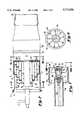
- FIG. 1is a schematic diagram of a gas turbine employing the combustor according to the current invention.
- FIG. 2is a longitudinal cross-section through the combustor of the current invention.
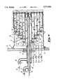
- FIG. 3is an isometric view of the front portion of the combustor shown in FIG. 2.
- FIG. 4is a longitudinal cross-section through the front portion of the combustor shown in FIG. 2 with the fuel piping and ignitor installed.
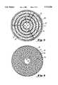
- FIG. 5is a cross-section through line V--V shown in FIG. 2.
- FIG. 6is a cross-section through line VI--VI shown in FIG. 2.
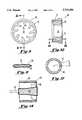
- FIG. 7is an enlarged view of the pilot section of the combustor shown in FIG. 4.
- FIG. 8is a view taken along line VIII--VIII shown in FIG. 7.
- FIG. 9is a front view of one of the swirlers shown in FIG. 2.
- FIG. 10is a cross-section through line X--X shown in FIG. 9.
- FIG. 11is a cross-section through line XI--XI shown in FIG. 10.
- FIG. 12is a cross-section through the fuel conduit shown in FIG. 4.
- FIG. 13is a longitudinal cross-section, partially schematic, through the combustor of the current invention in operation.
- FIG. 14is a longitudinal cross-section through an alternative embodiment of the pilot section of the combustor according to the current invention.
- FIG. 1a gas turbine 1.
- the gas turbineis comprised of a compressor 3 into which ambient air 2 is drawn.
- the compressor 3discharges compressed air 4 to a combustor 6 in which a fuel 5 is burned to produce a hot gas 7.
- the hot gas 7is expanded in a turbine 8 and then discharged as exhaust gas 9.
- the current inventionconcerns the combustor 6 for the gas turbine 1--specifically, a combustor designed to generate very low levels of NOx (e.g., less than approximately 9 ppmv when the gas turbine is operating at its base load firing temperature and without the use of water or steam injection).
- the combustor 6according to the current invention comprises a pre-mixing zone 10, in which air and fuel are mixed, and a combustion zone 12 downstream of the pre-mixing zone.
- Three large window-type openings 30are equally spaced around the circumference of the housing 27.
- a duct 28is attached to the aft end of the housing 27 and encloses the combustion zone 12. Cooling passages 31 are formed around the circumference of the duct 28 so as to allow the introduction of film cooling air. An outlet 56 is formed at the aft end of the duct 28 for discharging the hot gas produced in the combustor 6 to the turbine 8.
- the front flange 13 of the housing 27is mounted onto a plate 14, via screws 15, to facilitate mounting the combustor 6 into the combustion section of the gas turbine 1.
- five cylindrical liners 18-22are concentrically arranged in the mixing zone 10 of the combustor 6 so as form four annular passages 23-26, one annular passage being formed between each adjacent pair of liners.
- Each of the annular passageshas an inlet end 34 and a discharge end 35.
- Support struts 32are disposed adjacent the inlets 34 of each of the annular passages to strengthen the structure.
- a barrier plate 57is attached at the aft end of the liners 18-22, adjacent the discharges 35 of the annular passages, and separates the mixing portion 10 of the combustor from the combustion zone 12.
- a plurality of baffles 33extend both radially inward and outward from the liners 18-22 into the annular passages 23-26 around which the baffles are circumferentially distributed.
- a plurality of swirlers 59are disposed in the barrier plate 57 so as to be circumferentially distributed around each of the annular passages 23-26 adjacent their discharges 35.
- a typical swirler 59is shown in FIGS. 9 and 10 and is comprised of an outer ring from which a plurality of vanes 53 extend.
- the swirler vanes 53are adapted to impart rotation to the fuel and air flowing through the swirler 59. In so doing, they promote mixing of the fuel and air and cause recirculation that serves to anchor the flame.
- a centrally disposed passage 52is formed within the swirler 59 that allows fluid to flow through the barrier plate 57 without passing through the swirler vanes 53. By leaving some of the passages 52 open and plugging others, the amount of air flowing through each swirlers 59 can be adjusted to improve stability.
- each of the vanesis comprised of a metallic core 54 that has been coated with a catalytic material 55, such as a palladium and platinum composition, that promotes combustion at low temperatures and, hence, reduces the production of NOx.
- a catalytic material 55such as a palladium and platinum composition
- Suitable catalytic coatingsmay be obtained through Precision Combustion, Inc., of New Haven, Conn.
- a fuel assemblyis disposed in the combustor 6.
- the fuel assemblyis comprised of four concentric toroidal manifolds 70-73.
- Each fuel manifold 70-73is disposed just upstream of the inlet 34 of one of the annular passages 23-26.
- a plurality of rearward facing fuel discharge ports 47are distributed around the circumference of each of the manifolds 70-73.
- the discharge ports 47are spaced approximately 2 cm (0.75 inches) apart so that the fuel 5 is evenly distributed around the circumference of the annular passages 23-26.
- each of the fuel discharge ports 47is oriented at an angle A, as shown in FIG. 12, of approximately 18° so that it directs the fuel 5 at an angle into the radially outboard regions of each of the annular passages 23-26, as shown in FIG. 4, to promote mixing.
- one of four axially extending fuel supply tubes 74-77connects to each of the four fuel manifolds 70-73 so that each manifold is supplied with fuel 5 by a separate fuel supply tube.
- a flow control valve 78is installed in each fuel supply tube 74-77 in order to control the flow of fuel 5 from a fuel supply (not shown) to each fuel supply tube.
- the supply of fuel to each annular passage 23-26can be separately controlled.
- the fuelis a gaseous fuel, such as natural gas.
- the combustor 6is also provided with a pilot fuel assembly, mounted on the plate 14 by screws 16 that extend through a plate 17.
- the pilot assemblyincludes a fuel pipe 37 that supplies pilot fuel 5' to a pilot fuel tube 42.
- the pilot fuel tube 42discharges fuel 5' to a pilot fuel/air swirler 43 located within the innermost liner 18 and centered therein by spring clips 58, shown in FIG. 4.
- the pilot 43is comprised of inner and outer rings 61 and 62, respectively, and a plurality of swirler vanes 44 extending between the rings.
- the swirler vanes 44are adapted to impart rotation to the air and fuel flowing through the pilot 43, thereby ensuring good stability.
- An ignitor 40which may be of the conventional spark-gap type, is disposed within the inner ring 61 such that its tip extends just beyond the pilot 43.
- An electrical conduit 39 extending through the pilot fuel tube 42supplies power to the ignitor 40.
- a fuel pipe 38shown in FIG. 4, also supplies fuel 5", referred to as supplemental pilot fuel.
- the fuel pipe 38discharges the supplemental pilot fuel 5" to a conduit 41 that surrounds a portion of the pilot fuel tube 42. From the conduit 41, the supplemental pilot fuel 5" is directed to an annular passage 49 formed between the innermost liner 18 and the pilot fuel tube 42.
- the operation of the combustor 6is as follows. Although operation of only one combustor is discussed, it should be understood that the gas turbine 1 may incorporate a number of such combustors 6.
- the compressor 3is spun-up to ignition speed, typically approximately 18% to 20% of design speed, by a starting motor (not shown).
- ignition speedtypically approximately 18% to 20% of design speed
- the compressor rotoraccelerates, compressed air 4 from the compressor 3 flows into the combustor 6 through the three large window-type inlets 30, as shown in FIG. 4.
- the airAfter entering the combustor 6, the air is divided into five streams 4'--one stream flowing through each of the five annular passages 49 and 23-26.
- pilot fuel 5'When ignition speed is reached, pilot fuel 5' is introduced via the fuel pipe 37 and the pilot fuel tube 42. As shown in FIG. 7, in the pilot swirler 43, the pilot fuel 5' mixes in sufficient quantity with the air 4' flowing through annular passage 49 to provide a suitable mixture 67 of fuel and air to achieve ignition, i.e., a local fuel/air ratio of at least about 0.04 by weight. Combustion is established by supplying power, before the introduction of pilot fuel 5', to the ignitor 40.
- pilot flame 64is obtained in a central portion of the combustion zone 12 just downstream of the pilot 43, as shown in FIG. 13.
- Such combustionin which the fuel and air are mixed in a fuel rich ratio immediately upstream of the flame front is generally referred to as "diffusion" type combustion.
- a lean fuel/air mixtureis one in which the ratio of fuel to air is less that about 0.035 by weight.
- such ultra-lean pre-mixed combustionis obtained by introducing fuel 5 at lean fuel/air mixtures into the annular passages 23-26 surrounding the pilot fuel tube 42 via the fuel manifolds 70-73.
- the length of the passages and the presence of the turbulence inducing baffles 33promotes a high degree of mixing between the fuel and air.
- Such mixingensures that the resulting streams of fuel and air 66, shown in FIGS. 4 and 13, have lean fuel/air ratios throughout. As a result, there are no locally fuel rich zones that would promote the generation of NOx.
- the fuel/air mixtures 66After flowing through the annular passages 23-26, the fuel/air mixtures 66 exit the pre-mixing zone 10, via the swirlers 59, and enter the combustion zone 12. In the combustion zone 12, the lean fuel/air mixtures 66 are ignited by the pilot flame 64, thereby creating additional concentric flame fronts 80-83 within the combustion zone 12 that surround the pilot flame 64.
- fuel 5is supplied to the annular passages 23-26 sequentially.
- additional fuel 5beyond the fuel 5' available through the pilot fuel tube 42, is initially supplied to only the inner annular passage 23, via the fuel manifold 70 immediately upstream of that annular passage.
- supplemental pilot fuel 5"can be supplied to the innermost annular passage 49 via the fuel conduit 41. Again, the length of the passage 49 promotes good mixing of the fuel and air so as to create a lean fuel/air mixture 68, shown in FIG. 4. Subsequently, the pilot fuel 5' and its associated diffusion type combustion, which as previously discussed is a major source of NOx, can be eliminated and the lean pre-mix combustion of the supplemental pilot fuel 5" relied upon to maintain the pilot flame 64.
- the flame stability of combustion at the lean fuel/air ratios with which the combustor 6 of the current invention operates, except for the pilot fuel/air mixture 67,is poor, thereby creating the possibility of blow-out.
- good flame stabilityis achieved by the use of the pilot flame 64 in the center of the combustion zone and the use of swirlers 59, the cores 52 of some of which are plugged, at the discharge of each annular passage 23-26 that serve to anchor the flames 65.
- FIG. 14shows another embodiment of the pilot 43' of the current invention in which the spark-type ignitor 40 has been replaced by an ignitor comprised of an element 63 heated by electrical resistance to a temperature sufficient to ignite the fuel.
- the inner surface of the outer ring 62 and the outer surface of the heating element 63have been coated with a catalytic material, such as that previously discussed with respect to the swirler vanes 53.
Landscapes
- Engineering & Computer Science (AREA)
- Chemical & Material Sciences (AREA)
- Combustion & Propulsion (AREA)
- Mechanical Engineering (AREA)
- General Engineering & Computer Science (AREA)
- Chemical Kinetics & Catalysis (AREA)
- Toys (AREA)
Abstract
Description
This is a Continuation of application Ser. No. 08/046,320, filed Apr. 15, 1993, now U.S. Pat. No. 5,361,586.
The present invention relates to a combustor for burning fuel in compressed air. More specifically, the present invention relates to a combustor for a gas turbine that significantly reduces the amount of NOx produced by combustion.
In a gas turbine, fuel is burned in compressed air, produced by a compressor, in one or more combustors. Traditionally, such combustors had a primary combustion zone in which an approximately stoichiometric mixture of fuel and air was formed and burned in a diffusion type combustion process. Additional air was introduced into the combustor downstream of the primary combustion zone. Although the overall fuel/air ratio was considerably less than stoichiometric, the fuel/air mixture was readily ignited at start-up and good flame stability was achieved over a wide range in firing temperatures due to the locally richer nature of the fuel/air mixture in the primary combustion zone.
Unfortunately, use of such approximately stoichiometric fuel/air mixtures resulted in very high temperatures in the primary combustion zone. Such high temperatures promoted the formation of oxides of nitrogen ("NOx"), considered an atmospheric pollutant. Although it is known that combustion at lean fuel/air ratios reduces NOx formation, such lean mixtures are difficult to ignite and exhibit poor flame stability.
It is therefore desirable to provide a combustor capable of stable combustion with very lean mixtures of fuel and air, so as to reduce the formation of NOx, as well as one that permits reliable ignition at start-up.
Accordingly, it is the general object of the current invention to provide a combustor capable of stable combustion with very lean mixtures of fuel and air, so as to reduce the formation of NOx, as well as one that permits reliable ignition at start-up.
Briefly, this object, as well as other objects of the current invention, is accomplished in a gas turbine having a compressor for compressing air, a combustor for producing a hot gas by burning a fuel in the compressed air, and a turbine for expanding the hot gas produced by the combustor. The combustor has (i) a plurality of concentrically arranged annular passages each having an inlet end and a discharge end, (ii) a first fuel discharge port for each of the annular passages for introducing a fuel therein, and (iii) means for separately controlling the introduction of fuel into each of the annular passages via its fuel discharge port. In one embodiment, the combustor also has a plurality of swirlers for each of the annular passages that form an array distributed circumferentially around their respective annular passages. In this embodiment, the means for separately controlling the introduction of fuel into each of the annular passages via its fuel discharge port comprises an approximately toroidal manifold for each of the annular passages, each of the toroidal manifolds being disposed upstream of its respective annular passage.
The current invention also encompasses a method of burning fuel in compressed air, comprising the steps of (i) introducing a first stream of a fuel and air mixture into a central portion of a combustion zone, the fuel and air mixture in the first stream having a fuel to air ratio of at least about 0.04 by weight, (ii) igniting the first stream of fuel and air so as to create a central pilot flame in the combustion zone, (iii) introducing a second stream of a fuel and air mixture into a first portion of the combustion zone surrounding the central portion, the second fuel/air stream being introduced after the pilot flame is established, thereby creating a second flame surrounding the pilot flame, the second fuel/air stream having a fuel to air ratio of less than 0.035 by weight, and (iv) introducing a third stream of a fuel and air mixture into a second portion of the combustion zone surrounding the first portion, the third fuel/air stream being introduced after the second flame is established, thereby creating a third flame surrounding the second flame, the third fuel/air stream having a fuel to air ratio of less than 0.035 by weight.
FIG. 1 is a schematic diagram of a gas turbine employing the combustor according to the current invention.
FIG. 2 is a longitudinal cross-section through the combustor of the current invention.
FIG. 3 is an isometric view of the front portion of the combustor shown in FIG. 2.
FIG. 4 is a longitudinal cross-section through the front portion of the combustor shown in FIG. 2 with the fuel piping and ignitor installed.
FIG. 5 is a cross-section through line V--V shown in FIG. 2.
FIG. 6 is a cross-section through line VI--VI shown in FIG. 2.
FIG. 7 is an enlarged view of the pilot section of the combustor shown in FIG. 4.
FIG. 8 is a view taken along line VIII--VIII shown in FIG. 7.
FIG. 9 is a front view of one of the swirlers shown in FIG. 2.
FIG. 10 is a cross-section through line X--X shown in FIG. 9.
FIG. 11 is a cross-section through line XI--XI shown in FIG. 10.
FIG. 12 is a cross-section through the fuel conduit shown in FIG. 4.
FIG. 13 is a longitudinal cross-section, partially schematic, through the combustor of the current invention in operation.
FIG. 14 is a longitudinal cross-section through an alternative embodiment of the pilot section of the combustor according to the current invention.
Referring to the drawings, there is shown in FIG. 1 a gas turbine 1. As is conventional, the gas turbine is comprised of a compressor 3 into which ambient air 2 is drawn. The compressor 3 discharges compressed air 4 to acombustor 6 in which afuel 5 is burned to produce a hot gas 7. The hot gas 7 is expanded in a turbine 8 and then discharged as exhaust gas 9.
The current invention concerns thecombustor 6 for the gas turbine 1--specifically, a combustor designed to generate very low levels of NOx (e.g., less than approximately 9 ppmv when the gas turbine is operating at its base load firing temperature and without the use of water or steam injection). As shown in FIGS. 2 and 3, thecombustor 6 according to the current invention comprises a pre-mixing zone 10, in which air and fuel are mixed, and acombustion zone 12 downstream of the pre-mixing zone. Ahousing 27, having aflange 13 at its front end, encloses the mixing zone 10 of thecombustor 6. Three large window-type openings 30 are equally spaced around the circumference of thehousing 27. Aduct 28 is attached to the aft end of thehousing 27 and encloses thecombustion zone 12. Cooling passages 31 are formed around the circumference of theduct 28 so as to allow the introduction of film cooling air. An outlet 56 is formed at the aft end of theduct 28 for discharging the hot gas produced in thecombustor 6 to the turbine 8.
As shown in FIG. 4, thefront flange 13 of thehousing 27 is mounted onto a plate 14, viascrews 15, to facilitate mounting thecombustor 6 into the combustion section of the gas turbine 1. As also shown in FIG. 4, five cylindrical liners 18-22 are concentrically arranged in the mixing zone 10 of thecombustor 6 so as form four annular passages 23-26, one annular passage being formed between each adjacent pair of liners. Each of the annular passages has aninlet end 34 and adischarge end 35.Support struts 32 are disposed adjacent theinlets 34 of each of the annular passages to strengthen the structure. Abarrier plate 57 is attached at the aft end of the liners 18-22, adjacent thedischarges 35 of the annular passages, and separates the mixing portion 10 of the combustor from thecombustion zone 12.
As shown best in FIG. 5, a plurality ofbaffles 33 extend both radially inward and outward from the liners 18-22 into the annular passages 23-26 around which the baffles are circumferentially distributed. As shown best in FIG. 6, a plurality ofswirlers 59 are disposed in thebarrier plate 57 so as to be circumferentially distributed around each of the annular passages 23-26 adjacent theirdischarges 35. Atypical swirler 59 is shown in FIGS. 9 and 10 and is comprised of an outer ring from which a plurality ofvanes 53 extend. Theswirler vanes 53 are adapted to impart rotation to the fuel and air flowing through theswirler 59. In so doing, they promote mixing of the fuel and air and cause recirculation that serves to anchor the flame. A centrally disposedpassage 52 is formed within theswirler 59 that allows fluid to flow through thebarrier plate 57 without passing through theswirler vanes 53. By leaving some of thepassages 52 open and plugging others, the amount of air flowing through eachswirlers 59 can be adjusted to improve stability.
As shown in FIG. 11, in the preferred embodiment of the invention, each of the vanes is comprised of ametallic core 54 that has been coated with acatalytic material 55, such as a palladium and platinum composition, that promotes combustion at low temperatures and, hence, reduces the production of NOx. Suitable catalytic coatings may be obtained through Precision Combustion, Inc., of New Haven, Conn.
As shown in FIG. 4, a fuel assembly is disposed in thecombustor 6. The fuel assembly is comprised of four concentric toroidal manifolds 70-73. Each fuel manifold 70-73 is disposed just upstream of theinlet 34 of one of the annular passages 23-26. A plurality of rearward facingfuel discharge ports 47, one of which is shown in FIG. 12, are distributed around the circumference of each of the manifolds 70-73. In the preferred embodiment of the invention, thedischarge ports 47 are spaced approximately 2 cm (0.75 inches) apart so that thefuel 5 is evenly distributed around the circumference of the annular passages 23-26. In addition, each of thefuel discharge ports 47 is oriented at an angle A, as shown in FIG. 12, of approximately 18° so that it directs thefuel 5 at an angle into the radially outboard regions of each of the annular passages 23-26, as shown in FIG. 4, to promote mixing.
As shown in FIG. 4, one of four axially extending fuel supply tubes 74-77 connects to each of the four fuel manifolds 70-73 so that each manifold is supplied withfuel 5 by a separate fuel supply tube. Aflow control valve 78 is installed in each fuel supply tube 74-77 in order to control the flow offuel 5 from a fuel supply (not shown) to each fuel supply tube. Thus, according to the current invention, the supply of fuel to each annular passage 23-26 can be separately controlled. In the preferred embodiment, the fuel is a gaseous fuel, such as natural gas.
As shown in FIG. 4, thecombustor 6 is also provided with a pilot fuel assembly, mounted on the plate 14 by screws 16 that extend through a plate 17. The pilot assembly includes afuel pipe 37 that supplies pilot fuel 5' to apilot fuel tube 42. As shown best in FIG. 7, thepilot fuel tube 42 discharges fuel 5' to a pilot fuel/air swirler 43 located within theinnermost liner 18 and centered therein byspring clips 58, shown in FIG. 4. As shown in FIG. 7, thepilot 43 is comprised of inner andouter rings 61 and 62, respectively, and a plurality ofswirler vanes 44 extending between the rings. The swirler vanes 44 are adapted to impart rotation to the air and fuel flowing through thepilot 43, thereby ensuring good stability. Anignitor 40, which may be of the conventional spark-gap type, is disposed within the inner ring 61 such that its tip extends just beyond thepilot 43. Anelectrical conduit 39 extending through thepilot fuel tube 42 supplies power to theignitor 40.
Not all of the fuel supplied to thecombustor 6 flows through the fuel manifolds 70-73, which supplyfuel 5 to the annular passages 23-26, and thepilot fuel tube 42. Afuel pipe 38, shown in FIG. 4, also suppliesfuel 5", referred to as supplemental pilot fuel. Thefuel pipe 38 discharges thesupplemental pilot fuel 5" to aconduit 41 that surrounds a portion of thepilot fuel tube 42. From theconduit 41, thesupplemental pilot fuel 5" is directed to anannular passage 49 formed between theinnermost liner 18 and thepilot fuel tube 42.
The operation of thecombustor 6 is as follows. Although operation of only one combustor is discussed, it should be understood that the gas turbine 1 may incorporate a number ofsuch combustors 6. During start-up, the compressor 3 is spun-up to ignition speed, typically approximately 18% to 20% of design speed, by a starting motor (not shown). As the compressor rotor (not shown) accelerates, compressed air 4 from the compressor 3 flows into thecombustor 6 through the three large window-type inlets 30, as shown in FIG. 4. After entering thecombustor 6, the air is divided into five streams 4'--one stream flowing through each of the fiveannular passages 49 and 23-26.
When ignition speed is reached, pilot fuel 5' is introduced via thefuel pipe 37 and thepilot fuel tube 42. As shown in FIG. 7, in thepilot swirler 43, the pilot fuel 5' mixes in sufficient quantity with the air 4' flowing throughannular passage 49 to provide a suitable mixture 67 of fuel and air to achieve ignition, i.e., a local fuel/air ratio of at least about 0.04 by weight. Combustion is established by supplying power, before the introduction of pilot fuel 5', to theignitor 40.
As a result of the mixing provided within thepilot 43, the local fuel/air ratio of the fuel and air mixture 67 flowing through the pilot, and the flame anchoring effect of theswirler vanes 44, a verystable pilot flame 64 is obtained in a central portion of thecombustion zone 12 just downstream of thepilot 43, as shown in FIG. 13. Such combustion, in which the fuel and air are mixed in a fuel rich ratio immediately upstream of the flame front is generally referred to as "diffusion" type combustion.
Unfortunately, the diffusion type combustion associated with thepilot flame 64 results in locally high gas temperatures, and therefore, high rates of NOx formation. Thus, according to the current invention, as the speed of the gas turbine increases beyond ignition speed, the combustion of further fuel occurs in ultra-lean pre-mix type combustion, rather than further fuel rich diffusion type combustion. As is well known in the art, lean combustion minimizes local gas temperatures within the combustion zone and, therefore, the formation of NOx. As used herein, a lean fuel/air mixture is one in which the ratio of fuel to air is less that about 0.035 by weight.
According to the current invention, such ultra-lean pre-mixed combustion is obtained by introducingfuel 5 at lean fuel/air mixtures into the annular passages 23-26 surrounding thepilot fuel tube 42 via the fuel manifolds 70-73. As thefuel 5 flows through the annular passages 23-26, the length of the passages and the presence of theturbulence inducing baffles 33 promotes a high degree of mixing between the fuel and air. Such mixing ensures that the resulting streams of fuel and air 66, shown in FIGS. 4 and 13, have lean fuel/air ratios throughout. As a result, there are no locally fuel rich zones that would promote the generation of NOx. After flowing through the annular passages 23-26, the fuel/air mixtures 66 exit the pre-mixing zone 10, via theswirlers 59, and enter thecombustion zone 12. In thecombustion zone 12, the lean fuel/air mixtures 66 are ignited by thepilot flame 64, thereby creating additional concentric flame fronts 80-83 within thecombustion zone 12 that surround thepilot flame 64.
In the preferred embodiment,fuel 5 is supplied to the annular passages 23-26 sequentially. Thus, as increased loading on the turbine 8 demands higher temperatures of the hot gas 7,additional fuel 5, beyond the fuel 5' available through thepilot fuel tube 42, is initially supplied to only the innerannular passage 23, via the fuel manifold 70 immediately upstream of that annular passage. After the fuel/air mixture flowing throughannular passage 23 has been ignited, creating anannular flame 80 in a portion of the combustion zone surrounding thepilot flame 64, further increases in firing temperature are accomplished by increasing the fuel supplied toannular passage 23 by its fuel manifold 70 but only until the fuel/air ratio within that annular passage reaches approximately 0.035 by weight.
Thereafter, further increases in load are accomplished by supplying fuel toannular passage 24, via its fuel manifold 71, thereby creating a second annular flame 81 surrounding the firstannular flame 80. Additional fuel is supplied toannular passage 24 until its fuel/air ratio reaches 0.035 by weight. Still further increases in load are accomplished by supplying fuel, in a similar fashion, toannular passage 25, via itsfuel manifold 72, and lastly, to the outermostannular passage 26, via itsfuel manifold 73. The result is a flame that extends radially outward within thecombustion zone 12 as the firing temperature of thecombustor 6 increases without ever creating a rich fuel/air ratio stream. In this manner, very lean fuel/air mixtures 66, and therefore, low NOx production, can be maintained over the entire operating range.
As a further refinement, according to the current invention, after combustion is established with respect to the lean fuel/air mixtures 66 flowing through each of the annular passages 23-26,supplemental pilot fuel 5" can be supplied to the innermostannular passage 49 via thefuel conduit 41. Again, the length of thepassage 49 promotes good mixing of the fuel and air so as to create a lean fuel/air mixture 68, shown in FIG. 4. Subsequently, the pilot fuel 5' and its associated diffusion type combustion, which as previously discussed is a major source of NOx, can be eliminated and the lean pre-mix combustion of thesupplemental pilot fuel 5" relied upon to maintain thepilot flame 64.
Typically, the flame stability of combustion at the lean fuel/air ratios with which thecombustor 6 of the current invention operates, except for the pilot fuel/air mixture 67, is poor, thereby creating the possibility of blow-out. However, according to the current invention, good flame stability is achieved by the use of thepilot flame 64 in the center of the combustion zone and the use ofswirlers 59, thecores 52 of some of which are plugged, at the discharge of each annular passage 23-26 that serve to anchor the flames 65.
FIG. 14 shows another embodiment of the pilot 43' of the current invention in which the spark-type ignitor 40 has been replaced by an ignitor comprised of an element 63 heated by electrical resistance to a temperature sufficient to ignite the fuel. As shown in FIG. 14, in this embodiment, the inner surface of theouter ring 62 and the outer surface of the heating element 63 have been coated with a catalytic material, such as that previously discussed with respect to theswirler vanes 53.
Although the current invention has been discussed by reference gas fuel, the invention could also be practiced using other fuels. Also, although the invention has been discussed with reference to a combustor for a gas turbine, the invention could also be practiced with respect to combustors used in other types of machinery in which low NOx is desirable. Accordingly, the present invention may be embodied in other specific forms without departing from the spirit or essential attributes thereof and, accordingly, reference should be made to the appended claims, rather than to the foregoing specification, as indicating the scope of the invention.
Claims (16)
1. A gas turbine, comprising:
a) a compressor for compressing air;
b) a combustor for producing a hot gas by burning a fuel in said compressed air, said combustor having:
(i) a plurality of concentrically arranged annular passages each having an inlet end and a discharge end;
(ii) a first fuel discharge port for each of said annular passages for introducing a fuel therein; and
(iii) means for separately controlling the introduction of fuel into each of said annular passages via its fuel discharge port; and
c) a turbine for expanding said hot gas produced by said combustor.
2. The gas turbine according to claim 1, wherein said means for separately controlling the introduction of fuel into each of said annular passages via its fuel discharge port comprises an approximately toroidal manifold for each of said annular passages, each of said toroidal manifolds disposed proximate said inlet end of its respective annular passage, each of said first fuel discharge ports and a plurality of second fuel discharge ports formed in each of said toroidal manifolds and distributed circumferentially therearound.
3. The gas turbine according to claim 1, wherein each of said annular passages has means for introducing turbulence into a fluid flowing therein.
4. The gas turbine according to claim 3, wherein said turbulence inducing means comprises baffles.
5. The gas turbine according to claim 1, wherein said combustor further comprises a first swirler for each of said annular passages.
6. The gas turbine according to claim 1, wherein said combustor further comprises a plurality of swirlers for each of said annular passages, said swirlers forming an array of swirlers distributed circumferentially around each of said annular passages.
7. The gas turbine according to claim 6, wherein said swirlers are disposed proximate said discharge ends of said annular passages.
8. The gas turbine according to claim 6, wherein each of said swirlers comprises a plurality of vanes arranged circumferentially around said swirler.
9. The gas turbine according to claim 8, wherein each of said swirler vanes is coated with a catalytic material.
10. The gas turbine according to claim 6, further comprising a plate disposed downstream of said discharge ends of said annular passages, each of said swirlers disposed in said plate.
11. The gas turbine according to claim 1, wherein said combustor further comprises:
a) a fuel conduit enclosed by said annular passages and concentric therewith, said fuel conduit having a discharge port;
b) a swirler disposed downstream of said fuel conduit discharge port; and
c) means for igniting a fuel/air mixture disposed downstream of said fuel conduit discharge port.
12. The gas turbine according to claim 11, wherein said igniting means comprises an element heated by electrical resistance.
13. The gas turbine according to claim 12, wherein said heated element is coated with a catalytic material.
14. The gas turbine according to claim 11, wherein each of said annular passages is a first annular passage, one of said first annular passages being innermost with respect to the other of said first annular passages, and wherein said combustor further comprises a second annular passage formed between said fuel conduit and said innermost first annular passage.
15. The gas turbine according to claim 14, further comprising a second fuel discharge port for introducing a fuel into said second annular passage.
16. The gas turbine according to claim 1, wherein at least a portion of said combustor is formed from a catalytic material.
Priority Applications (1)
| Application Number | Priority Date | Filing Date | Title |
|---|---|---|---|
| US08/623,059US5713206A (en) | 1993-04-15 | 1994-10-17 | Gas turbine ultra low NOx combustor |
Applications Claiming Priority (2)
| Application Number | Priority Date | Filing Date | Title |
|---|---|---|---|
| US08/046,320US5361586A (en) | 1993-04-15 | 1993-04-15 | Gas turbine ultra low NOx combustor |
| US08/623,059US5713206A (en) | 1993-04-15 | 1994-10-17 | Gas turbine ultra low NOx combustor |
Related Parent Applications (1)
| Application Number | Title | Priority Date | Filing Date |
|---|---|---|---|
| US08/046,320ContinuationUS5361586A (en) | 1993-04-15 | 1993-04-15 | Gas turbine ultra low NOx combustor |
Publications (1)
| Publication Number | Publication Date |
|---|---|
| US5713206Atrue US5713206A (en) | 1998-02-03 |
Family
ID=21942823
Family Applications (2)
| Application Number | Title | Priority Date | Filing Date |
|---|---|---|---|
| US08/046,320Expired - Fee RelatedUS5361586A (en) | 1993-04-15 | 1993-04-15 | Gas turbine ultra low NOx combustor |
| US08/623,059Expired - Fee RelatedUS5713206A (en) | 1993-04-15 | 1994-10-17 | Gas turbine ultra low NOx combustor |
Family Applications Before (1)
| Application Number | Title | Priority Date | Filing Date |
|---|---|---|---|
| US08/046,320Expired - Fee RelatedUS5361586A (en) | 1993-04-15 | 1993-04-15 | Gas turbine ultra low NOx combustor |
Country Status (7)
| Country | Link |
|---|---|
| US (2) | US5361586A (en) |
| EP (2) | EP0766045B1 (en) |
| JP (1) | JPH06323543A (en) |
| CA (1) | CA2121314A1 (en) |
| DE (2) | DE69405281T2 (en) |
| ES (1) | ES2108938T3 (en) |
| TW (1) | TW230233B (en) |
Cited By (109)
| Publication number | Priority date | Publication date | Assignee | Title |
|---|---|---|---|---|
| GB2327120A (en)* | 1997-07-09 | 1999-01-13 | Deutsch Zentr Luft & Raumfahrt | Atomising nozzle for premix burners |
| US6092363A (en)* | 1998-06-19 | 2000-07-25 | Siemens Westinghouse Power Corporation | Low Nox combustor having dual fuel injection system |
| US6121628A (en)* | 1999-03-31 | 2000-09-19 | Siemens Westinghouse Power Corporation | Method, gas turbine, and combustor apparatus for sensing fuel quality |
| WO2000063616A3 (en)* | 1999-04-19 | 2001-02-22 | North American Mfg | Premix burner with firing rate control |
| US6253555B1 (en) | 1998-08-21 | 2001-07-03 | Rolls-Royce Plc | Combustion chamber comprising mixing ducts with fuel injectors varying in number and cross-sectional area |
| US6374615B1 (en) | 2000-01-28 | 2002-04-23 | Alliedsignal, Inc | Low cost, low emissions natural gas combustor |
| US6652265B2 (en) | 2000-12-06 | 2003-11-25 | North American Manufacturing Company | Burner apparatus and method |
| US6672862B2 (en) | 2000-03-24 | 2004-01-06 | North American Manufacturing Company | Premix burner with integral mixers and supplementary burner system |
| US20040060301A1 (en)* | 2002-09-27 | 2004-04-01 | Chen Alexander G. | Multi-point staging strategy for low emission and stable combustion |
| US20040144098A1 (en)* | 2000-02-24 | 2004-07-29 | Willis Jeffrey W. | Multi-stage multi-plane combustion method for a gas turbine engine |
| US20040172951A1 (en)* | 2001-07-19 | 2004-09-09 | Frank Hannemann | Method for operating a burner of a gas turbine and a power plant |
| US20050016178A1 (en)* | 2002-12-23 | 2005-01-27 | Siemens Westinghouse Power Corporation | Gas turbine can annular combustor |
| US20050032013A1 (en)* | 2001-01-30 | 2005-02-10 | Dirk Bueche | Burner unit and method for operation thereof |
| US20050056313A1 (en)* | 2003-09-12 | 2005-03-17 | Hagen David L. | Method and apparatus for mixing fluids |
| US20050118732A1 (en)* | 1996-07-30 | 2005-06-02 | Yasuo Yamao | Immunoassay method for lyzed whole blood |
| US20050196714A1 (en)* | 2002-08-30 | 2005-09-08 | Alstom Technology, Ltd. | Hybrid burner and associated operating method |
| EP1596132A1 (en)* | 2004-05-11 | 2005-11-16 | United Technologies Corporation | Nozzle |
| US20050252218A1 (en)* | 2004-05-11 | 2005-11-17 | Chen Alexander G | Nozzle |
| JP2006523294A (en)* | 2003-01-22 | 2006-10-12 | ヴァスト・パワー・システムズ・インコーポレーテッド | Reactor |
| US7137809B2 (en)* | 2001-01-30 | 2006-11-21 | Alstom Technology Ltd. | Method for the production of a burner unit |
| US20070089427A1 (en)* | 2005-10-24 | 2007-04-26 | Thomas Scarinci | Two-branch mixing passage and method to control combustor pulsations |
| US20070287108A1 (en)* | 2004-01-22 | 2007-12-13 | Linde Aktiengesellschaft | Apparatus and Method for a Burner |
| US20090229269A1 (en)* | 2008-03-12 | 2009-09-17 | General Electric Company | Lean direct injection combustion system |
| US20110000671A1 (en)* | 2008-03-28 | 2011-01-06 | Frank Hershkowitz | Low Emission Power Generation and Hydrocarbon Recovery Systems and Methods |
| US20110031333A1 (en)* | 2009-08-04 | 2011-02-10 | Delavan Inc | Multi-point injector ring |
| US8322143B2 (en)* | 2011-01-18 | 2012-12-04 | General Electric Company | System and method for injecting fuel |
| US20130186092A1 (en)* | 2012-01-23 | 2013-07-25 | General Electric Company | Micromixer of turbine system |
| US20130288190A1 (en)* | 2010-12-01 | 2013-10-31 | Johannes Hermanus Maria Disselhorst | Burner |
| US20140007581A1 (en)* | 2012-07-06 | 2014-01-09 | Richard S. Tuthill | Fuel flexible fuel injector |
| WO2014127306A1 (en)* | 2013-02-14 | 2014-08-21 | Clearsign Combustion Corporation | SELECTABLE DILUTION LOW NOx BURNER |
| US8899048B2 (en) | 2010-11-24 | 2014-12-02 | Delavan Inc. | Low calorific value fuel combustion systems for gas turbine engines |
| CN104315541A (en)* | 2014-09-26 | 2015-01-28 | 北京华清燃气轮机与煤气化联合循环工程技术有限公司 | Duty-stage spray nozzle of combustion chamber and use method of spray nozzle |
| US8984857B2 (en) | 2008-03-28 | 2015-03-24 | Exxonmobil Upstream Research Company | Low emission power generation and hydrocarbon recovery systems and methods |
| US9003804B2 (en) | 2010-11-24 | 2015-04-14 | Delavan Inc | Multipoint injectors with auxiliary stage |
| US9027321B2 (en) | 2008-03-28 | 2015-05-12 | Exxonmobil Upstream Research Company | Low emission power generation and hydrocarbon recovery systems and methods |
| WO2015134009A1 (en)* | 2014-03-05 | 2015-09-11 | Siemens Aktiengesellschaft | Gas turbine engine with compressor exhaust flow static mixing system |
| US9188063B2 (en) | 2011-11-03 | 2015-11-17 | Delavan Inc. | Injectors for multipoint injection |
| US9222671B2 (en) | 2008-10-14 | 2015-12-29 | Exxonmobil Upstream Research Company | Methods and systems for controlling the products of combustion |
| US9333518B2 (en) | 2013-02-27 | 2016-05-10 | Delavan Inc | Multipoint injectors |
| US9353682B2 (en) | 2012-04-12 | 2016-05-31 | General Electric Company | Methods, systems and apparatus relating to combustion turbine power plants with exhaust gas recirculation |
| US9377190B2 (en) | 2013-02-14 | 2016-06-28 | Clearsign Combustion Corporation | Burner with a perforated flame holder and pre-heat apparatus |
| US9463417B2 (en) | 2011-03-22 | 2016-10-11 | Exxonmobil Upstream Research Company | Low emission power generation systems and methods incorporating carbon dioxide separation |
| US9500370B2 (en) | 2013-12-20 | 2016-11-22 | General Electric Company | Apparatus for mixing fuel in a gas turbine nozzle |
| US9512759B2 (en) | 2013-02-06 | 2016-12-06 | General Electric Company | System and method for catalyst heat utilization for gas turbine with exhaust gas recirculation |
| US9574496B2 (en) | 2012-12-28 | 2017-02-21 | General Electric Company | System and method for a turbine combustor |
| US9581081B2 (en) | 2013-01-13 | 2017-02-28 | General Electric Company | System and method for protecting components in a gas turbine engine with exhaust gas recirculation |
| US9587510B2 (en) | 2013-07-30 | 2017-03-07 | General Electric Company | System and method for a gas turbine engine sensor |
| US9599021B2 (en) | 2011-03-22 | 2017-03-21 | Exxonmobil Upstream Research Company | Systems and methods for controlling stoichiometric combustion in low emission turbine systems |
| US9599070B2 (en) | 2012-11-02 | 2017-03-21 | General Electric Company | System and method for oxidant compression in a stoichiometric exhaust gas recirculation gas turbine system |
| US9611756B2 (en) | 2012-11-02 | 2017-04-04 | General Electric Company | System and method for protecting components in a gas turbine engine with exhaust gas recirculation |
| US9617914B2 (en) | 2013-06-28 | 2017-04-11 | General Electric Company | Systems and methods for monitoring gas turbine systems having exhaust gas recirculation |
| US9618261B2 (en) | 2013-03-08 | 2017-04-11 | Exxonmobil Upstream Research Company | Power generation and LNG production |
| US9631542B2 (en) | 2013-06-28 | 2017-04-25 | General Electric Company | System and method for exhausting combustion gases from gas turbine engines |
| US9631815B2 (en) | 2012-12-28 | 2017-04-25 | General Electric Company | System and method for a turbine combustor |
| US9644844B2 (en) | 2011-11-03 | 2017-05-09 | Delavan Inc. | Multipoint fuel injection arrangements |
| US9670841B2 (en) | 2011-03-22 | 2017-06-06 | Exxonmobil Upstream Research Company | Methods of varying low emission turbine gas recycle circuits and systems and apparatus related thereto |
| US9689309B2 (en) | 2011-03-22 | 2017-06-27 | Exxonmobil Upstream Research Company | Systems and methods for carbon dioxide capture in low emission combined turbine systems |
| US9708977B2 (en) | 2012-12-28 | 2017-07-18 | General Electric Company | System and method for reheat in gas turbine with exhaust gas recirculation |
| US9732673B2 (en) | 2010-07-02 | 2017-08-15 | Exxonmobil Upstream Research Company | Stoichiometric combustion with exhaust gas recirculation and direct contact cooler |
| US9732675B2 (en) | 2010-07-02 | 2017-08-15 | Exxonmobil Upstream Research Company | Low emission power generation systems and methods |
| US9745936B2 (en) | 2012-02-16 | 2017-08-29 | Delavan Inc | Variable angle multi-point injection |
| US9752458B2 (en) | 2013-12-04 | 2017-09-05 | General Electric Company | System and method for a gas turbine engine |
| US9784185B2 (en) | 2012-04-26 | 2017-10-10 | General Electric Company | System and method for cooling a gas turbine with an exhaust gas provided by the gas turbine |
| US9784140B2 (en) | 2013-03-08 | 2017-10-10 | Exxonmobil Upstream Research Company | Processing exhaust for use in enhanced oil recovery |
| US9784182B2 (en) | 2013-03-08 | 2017-10-10 | Exxonmobil Upstream Research Company | Power generation and methane recovery from methane hydrates |
| US9803865B2 (en) | 2012-12-28 | 2017-10-31 | General Electric Company | System and method for a turbine combustor |
| US9810050B2 (en) | 2011-12-20 | 2017-11-07 | Exxonmobil Upstream Research Company | Enhanced coal-bed methane production |
| US9819292B2 (en) | 2014-12-31 | 2017-11-14 | General Electric Company | Systems and methods to respond to grid overfrequency events for a stoichiometric exhaust recirculation gas turbine |
| US9835089B2 (en) | 2013-06-28 | 2017-12-05 | General Electric Company | System and method for a fuel nozzle |
| US9863267B2 (en) | 2014-01-21 | 2018-01-09 | General Electric Company | System and method of control for a gas turbine engine |
| US9869247B2 (en) | 2014-12-31 | 2018-01-16 | General Electric Company | Systems and methods of estimating a combustion equivalence ratio in a gas turbine with exhaust gas recirculation |
| US9869279B2 (en) | 2012-11-02 | 2018-01-16 | General Electric Company | System and method for a multi-wall turbine combustor |
| US9885290B2 (en) | 2014-06-30 | 2018-02-06 | General Electric Company | Erosion suppression system and method in an exhaust gas recirculation gas turbine system |
| US9897321B2 (en) | 2015-03-31 | 2018-02-20 | Delavan Inc. | Fuel nozzles |
| US9903588B2 (en) | 2013-07-30 | 2018-02-27 | General Electric Company | System and method for barrier in passage of combustor of gas turbine engine with exhaust gas recirculation |
| US9903316B2 (en) | 2010-07-02 | 2018-02-27 | Exxonmobil Upstream Research Company | Stoichiometric combustion of enriched air with exhaust gas recirculation |
| US9903271B2 (en) | 2010-07-02 | 2018-02-27 | Exxonmobil Upstream Research Company | Low emission triple-cycle power generation and CO2 separation systems and methods |
| US9915200B2 (en) | 2014-01-21 | 2018-03-13 | General Electric Company | System and method for controlling the combustion process in a gas turbine operating with exhaust gas recirculation |
| US9932874B2 (en) | 2013-02-21 | 2018-04-03 | Exxonmobil Upstream Research Company | Reducing oxygen in a gas turbine exhaust |
| US9938861B2 (en) | 2013-02-21 | 2018-04-10 | Exxonmobil Upstream Research Company | Fuel combusting method |
| US9951658B2 (en) | 2013-07-31 | 2018-04-24 | General Electric Company | System and method for an oxidant heating system |
| US10012151B2 (en) | 2013-06-28 | 2018-07-03 | General Electric Company | Systems and methods for controlling exhaust gas flow in exhaust gas recirculation gas turbine systems |
| US10030588B2 (en) | 2013-12-04 | 2018-07-24 | General Electric Company | Gas turbine combustor diagnostic system and method |
| US10047633B2 (en) | 2014-05-16 | 2018-08-14 | General Electric Company | Bearing housing |
| US10060359B2 (en) | 2014-06-30 | 2018-08-28 | General Electric Company | Method and system for combustion control for gas turbine system with exhaust gas recirculation |
| US10079564B2 (en) | 2014-01-27 | 2018-09-18 | General Electric Company | System and method for a stoichiometric exhaust gas recirculation gas turbine system |
| US10094566B2 (en) | 2015-02-04 | 2018-10-09 | General Electric Company | Systems and methods for high volumetric oxidant flow in gas turbine engine with exhaust gas recirculation |
| US10100741B2 (en) | 2012-11-02 | 2018-10-16 | General Electric Company | System and method for diffusion combustion with oxidant-diluent mixing in a stoichiometric exhaust gas recirculation gas turbine system |
| US10107495B2 (en) | 2012-11-02 | 2018-10-23 | General Electric Company | Gas turbine combustor control system for stoichiometric combustion in the presence of a diluent |
| US10145269B2 (en) | 2015-03-04 | 2018-12-04 | General Electric Company | System and method for cooling discharge flow |
| US10208677B2 (en) | 2012-12-31 | 2019-02-19 | General Electric Company | Gas turbine load control system |
| US10215412B2 (en) | 2012-11-02 | 2019-02-26 | General Electric Company | System and method for load control with diffusion combustion in a stoichiometric exhaust gas recirculation gas turbine system |
| US10221762B2 (en) | 2013-02-28 | 2019-03-05 | General Electric Company | System and method for a turbine combustor |
| US10227920B2 (en) | 2014-01-15 | 2019-03-12 | General Electric Company | Gas turbine oxidant separation system |
| US10253690B2 (en) | 2015-02-04 | 2019-04-09 | General Electric Company | Turbine system with exhaust gas recirculation, separation and extraction |
| US10267270B2 (en) | 2015-02-06 | 2019-04-23 | General Electric Company | Systems and methods for carbon black production with a gas turbine engine having exhaust gas recirculation |
| US10273880B2 (en) | 2012-04-26 | 2019-04-30 | General Electric Company | System and method of recirculating exhaust gas for use in a plurality of flow paths in a gas turbine engine |
| US10316746B2 (en) | 2015-02-04 | 2019-06-11 | General Electric Company | Turbine system with exhaust gas recirculation, separation and extraction |
| US10315150B2 (en) | 2013-03-08 | 2019-06-11 | Exxonmobil Upstream Research Company | Carbon dioxide recovery |
| US10385809B2 (en) | 2015-03-31 | 2019-08-20 | Delavan Inc. | Fuel nozzles |
| US10480792B2 (en) | 2015-03-06 | 2019-11-19 | General Electric Company | Fuel staging in a gas turbine engine |
| US10570826B2 (en)* | 2017-09-25 | 2020-02-25 | Delavan Inc. | Fuel manifold with nested annular passages and radially extending channels |
| US10571124B2 (en) | 2013-02-14 | 2020-02-25 | Clearsign Combustion Corporation | Selectable dilution low NOx burner |
| US10655542B2 (en) | 2014-06-30 | 2020-05-19 | General Electric Company | Method and system for startup of gas turbine system drive trains with exhaust gas recirculation |
| EP3667168A1 (en)* | 2018-12-14 | 2020-06-17 | Delavan, Inc. | Injection system with radial in-flow swirl premix gas fuel injectors |
| US10774748B2 (en)* | 2017-01-17 | 2020-09-15 | Delavan Inc. | Internal fuel manifolds |
| US10775047B2 (en) | 2014-05-30 | 2020-09-15 | Kawasaki Jukogyo Kabushiki Kaisha | Combustor for gas turbine engine |
| US10788212B2 (en) | 2015-01-12 | 2020-09-29 | General Electric Company | System and method for an oxidant passageway in a gas turbine system with exhaust gas recirculation |
| US11353212B2 (en)* | 2019-09-12 | 2022-06-07 | Zeeco, Inc. | Low NOxburner apparatus and method |
Families Citing this family (113)
| Publication number | Priority date | Publication date | Assignee | Title |
|---|---|---|---|---|
| JPH071990B2 (en)* | 1988-07-07 | 1995-01-11 | 三菱電機株式会社 | Permanent magnet type rotating electric machine |
| US5361586A (en)* | 1993-04-15 | 1994-11-08 | Westinghouse Electric Corporation | Gas turbine ultra low NOx combustor |
| US5623826A (en)* | 1993-07-30 | 1997-04-29 | Hitachi, Ltd. | Combustor having a premix chamber with a blade-like structural member and method of operating the combustor |
| JP2954480B2 (en)* | 1994-04-08 | 1999-09-27 | 株式会社日立製作所 | Gas turbine combustor |
| US5943866A (en)* | 1994-10-03 | 1999-08-31 | General Electric Company | Dynamically uncoupled low NOx combustor having multiple premixers with axial staging |
| DE4439619A1 (en)* | 1994-11-05 | 1996-05-09 | Abb Research Ltd | Method and device for operating a premix burner |
| DE4446842B4 (en)† | 1994-12-27 | 2006-08-10 | Alstom | Method and device for feeding a gaseous fuel into a premix burner |
| GB2298916B (en)* | 1995-03-15 | 1998-11-04 | Rolls Royce Plc | Annular combustor |
| US5722230A (en)* | 1995-08-08 | 1998-03-03 | General Electric Co. | Center burner in a multi-burner combustor |
| DE19545311B4 (en)* | 1995-12-05 | 2006-09-14 | Alstom | Method for operating a combustion chamber equipped with premix burners |
| US5881756A (en)* | 1995-12-22 | 1999-03-16 | Institute Of Gas Technology | Process and apparatus for homogeneous mixing of gaseous fluids |
| JP2858104B2 (en)* | 1996-02-05 | 1999-02-17 | 三菱重工業株式会社 | Gas turbine combustor |
| WO1997040316A1 (en)* | 1996-04-19 | 1997-10-30 | Westinghouse Electric Corporation | Premixed combustor with flashback arrestors |
| US5797268A (en)* | 1996-07-05 | 1998-08-25 | Westinghouse Electric Corporation | Partially swirled multi-swirl combustor plate and chimneys |
| DE19628960B4 (en)* | 1996-07-18 | 2005-06-02 | Alstom Technology Ltd | temperature measuring |
| US5857320A (en)* | 1996-11-12 | 1999-01-12 | Westinghouse Electric Corporation | Combustor with flashback arresting system |
| WO1998025084A1 (en)* | 1996-12-04 | 1998-06-11 | Siemens Westinghouse Power Corporation | DIFFUSION AND PREMIX PILOT BURNER FOR LOW NOx COMBUSTOR |
| US5941698A (en)* | 1996-12-11 | 1999-08-24 | Siemens Westinghouse Power Corporation | Gas pilot with radially displaced, high momentum fuel outlet, and method thereof |
| JP3448190B2 (en)* | 1997-08-29 | 2003-09-16 | 三菱重工業株式会社 | Gas turbine combustor |
| US5983642A (en)* | 1997-10-13 | 1999-11-16 | Siemens Westinghouse Power Corporation | Combustor with two stage primary fuel tube with concentric members and flow regulating |
| US6109038A (en)* | 1998-01-21 | 2000-08-29 | Siemens Westinghouse Power Corporation | Combustor with two stage primary fuel assembly |
| JP4205231B2 (en) | 1998-02-10 | 2009-01-07 | ゼネラル・エレクトリック・カンパニイ | Burner |
| DE19812834B4 (en)* | 1998-03-24 | 2004-12-16 | Alstom | Process for igniting the burners of combustion chambers in gas turbine plants |
| US6268913B1 (en) | 1999-02-26 | 2001-07-31 | Siemens Westinghouse Power Corporation | Method and combustor apparatus for sensing the level of a contaminant within a combustion flame |
| ES2258324T3 (en)* | 1999-09-09 | 2006-08-16 | Giorgio Scanferla | BURNER ASSEMBLY AND BURNER HEAD FOR FUEL / COMBURENT GASEOUS BLENDS. |
| WO2001044720A1 (en)* | 1999-12-15 | 2001-06-21 | Osaka Gas Co., Ltd. | Fluid distributor, burner device, gas turbine engine, and cogeneration system |
| JP3543717B2 (en)* | 2000-02-18 | 2004-07-21 | 日産自動車株式会社 | Catalytic combustor |
| DE10042315A1 (en)* | 2000-08-29 | 2002-03-14 | Alstom Power Nv | Burner for heat generator comprises three injectors for gaseous or liquid fuel, swirl generator, mixing section , and transfer ducts |
| US6575734B1 (en)* | 2000-08-30 | 2003-06-10 | Gencor Industries, Inc. | Low emissions burner with premix flame stabilized by a diffusion flame |
| US6363724B1 (en) | 2000-08-31 | 2002-04-02 | General Electric Company | Gas only nozzle fuel tip |
| US6442939B1 (en)* | 2000-12-22 | 2002-09-03 | Pratt & Whitney Canada Corp. | Diffusion mixer |
| EP1255077B1 (en) | 2001-04-30 | 2008-06-11 | ALSTOM Technology Ltd | Device for the combustion of a gaseous mixture of fuel and oxidant |
| US6467272B1 (en)* | 2001-06-25 | 2002-10-22 | Power Systems Mfg, Llc | Means for wear reduction in a gas turbine combustor |
| US6755024B1 (en)* | 2001-08-23 | 2004-06-29 | Delavan Inc. | Multiplex injector |
| US6666029B2 (en) | 2001-12-06 | 2003-12-23 | Siemens Westinghouse Power Corporation | Gas turbine pilot burner and method |
| US6893251B2 (en) | 2002-03-16 | 2005-05-17 | Exxon Mobil Chemical Patents Inc. | Burner design for reduced NOx emissions |
| US6881053B2 (en) | 2002-03-16 | 2005-04-19 | Exxonmobil Chemical Patents Inc. | Burner with high capacity venturi |
| WO2003081129A1 (en) | 2002-03-16 | 2003-10-02 | Exxonmobil Chemical Patents Inc. | Burner tip and seal for optimizing burner performance |
| US7322818B2 (en) | 2002-03-16 | 2008-01-29 | Exxonmobil Chemical Patents Inc. | Method for adjusting pre-mix burners to reduce NOx emissions |
| US6887068B2 (en) | 2002-03-16 | 2005-05-03 | Exxonmobil Chemical Patents Inc. | Centering plate for burner |
| US6869277B2 (en) | 2002-03-16 | 2005-03-22 | Exxonmobil Chemical Patents Inc. | Burner employing cooled flue gas recirculation |
| DE60334535D1 (en)* | 2002-03-16 | 2010-11-25 | Exxonmobil Chem Patents Inc | SOLDERABLE IGNITION COVER FOR A BURNER |
| US6866502B2 (en) | 2002-03-16 | 2005-03-15 | Exxonmobil Chemical Patents Inc. | Burner system employing flue gas recirculation |
| US6890172B2 (en) | 2002-03-16 | 2005-05-10 | Exxonmobil Chemical Patents Inc. | Burner with flue gas recirculation |
| US6846175B2 (en) | 2002-03-16 | 2005-01-25 | Exxonmobil Chemical Patents Inc. | Burner employing flue-gas recirculation system |
| US6986658B2 (en) | 2002-03-16 | 2006-01-17 | Exxonmobil Chemical Patents, Inc. | Burner employing steam injection |
| AU2003225834A1 (en) | 2002-03-16 | 2003-10-08 | Exxonmobil Chemical Patents Inc. | Improved burner with low nox emissions |
| US6893252B2 (en) | 2002-03-16 | 2005-05-17 | Exxonmobil Chemical Patents Inc. | Fuel spud for high temperature burners |
| DE10257704A1 (en) | 2002-12-11 | 2004-07-15 | Alstom Technology Ltd | Method of burning a fuel |
| US7249461B2 (en) | 2003-08-22 | 2007-07-31 | Siemens Power Generation, Inc. | Turbine fuel ring assembly |
| EP1531305A1 (en)* | 2003-11-12 | 2005-05-18 | United Technologies Corporation | Multi-point fuel injector |
| US7654088B2 (en)* | 2004-02-27 | 2010-02-02 | Pratt & Whitney Canada Corp. | Dual conduit fuel manifold for gas turbine engine |
| US20080280238A1 (en)* | 2007-05-07 | 2008-11-13 | Caterpillar Inc. | Low swirl injector and method for low-nox combustor |
| JP5147938B2 (en)* | 2007-07-02 | 2013-02-20 | シーメンス アクチエンゲゼルシヤフト | Burner and burner operation method |
| US20090211255A1 (en)* | 2008-02-21 | 2009-08-27 | General Electric Company | Gas turbine combustor flame stabilizer |
| EP2110601A1 (en)* | 2008-04-15 | 2009-10-21 | Siemens Aktiengesellschaft | Burner |
| US20120047902A1 (en)* | 2008-10-15 | 2012-03-01 | Tuthill Richard S | Fuel delivery system for a turbine engine |
| EP2192347B1 (en)* | 2008-11-26 | 2014-01-01 | Siemens Aktiengesellschaft | Tubular swirling chamber |
| US8079218B2 (en) | 2009-05-21 | 2011-12-20 | General Electric Company | Method and apparatus for combustor nozzle with flameholding protection |
| JP5372815B2 (en)* | 2010-03-17 | 2013-12-18 | 株式会社日立製作所 | Gas turbine combustor |
| US8418468B2 (en) | 2010-04-06 | 2013-04-16 | General Electric Company | Segmented annular ring-manifold quaternary fuel distributor |
| US8438852B2 (en) | 2010-04-06 | 2013-05-14 | General Electric Company | Annular ring-manifold quaternary fuel distributor |
| US8875516B2 (en)* | 2011-02-04 | 2014-11-04 | General Electric Company | Turbine combustor configured for high-frequency dynamics mitigation and related method |
| US9388985B2 (en)* | 2011-07-29 | 2016-07-12 | General Electric Company | Premixing apparatus for gas turbine system |
| US20130091848A1 (en)* | 2011-10-14 | 2013-04-18 | General Electric Company | Annular flow conditioning member for gas turbomachine combustor assembly |
| US9322557B2 (en)* | 2012-01-05 | 2016-04-26 | General Electric Company | Combustor and method for distributing fuel in the combustor |
| US20130199189A1 (en)* | 2012-02-08 | 2013-08-08 | Jong Ho Uhm | Fuel injection assembly for use in turbine engines and method of assembling same |
| US20130199190A1 (en)* | 2012-02-08 | 2013-08-08 | Jong Ho Uhm | Fuel injection assembly for use in turbine engines and method of assembling same |
| US9341376B2 (en)* | 2012-02-20 | 2016-05-17 | General Electric Company | Combustor and method for supplying fuel to a combustor |
| US20130283802A1 (en)* | 2012-04-27 | 2013-10-31 | General Electric Company | Combustor |
| US9261279B2 (en)* | 2012-05-25 | 2016-02-16 | General Electric Company | Liquid cartridge with passively fueled premixed air blast circuit for gas operation |
| US20130327050A1 (en)* | 2012-06-07 | 2013-12-12 | General Electric Company | Controlling flame stability of a gas turbine generator |
| US20140061327A1 (en)* | 2012-08-31 | 2014-03-06 | General Electric Company | System and method for staging fuel to a combustor |
| JP5972125B2 (en)* | 2012-09-12 | 2016-08-17 | 三菱日立パワーシステムズ株式会社 | Gas turbine combustor |
| US9677766B2 (en)* | 2012-11-28 | 2017-06-13 | General Electric Company | Fuel nozzle for use in a turbine engine and method of assembly |
| US9291103B2 (en)* | 2012-12-05 | 2016-03-22 | General Electric Company | Fuel nozzle for a combustor of a gas turbine engine |
| US9151503B2 (en)* | 2013-01-04 | 2015-10-06 | General Electric Company | Coaxial fuel supply for a micromixer |
| US9422867B2 (en)* | 2013-02-06 | 2016-08-23 | General Electric Company | Variable volume combustor with center hub fuel staging |
| US9759425B2 (en) | 2013-03-12 | 2017-09-12 | General Electric Company | System and method having multi-tube fuel nozzle with multiple fuel injectors |
| US9528444B2 (en) | 2013-03-12 | 2016-12-27 | General Electric Company | System having multi-tube fuel nozzle with floating arrangement of mixing tubes |
| US9651259B2 (en) | 2013-03-12 | 2017-05-16 | General Electric Company | Multi-injector micromixing system |
| US9650959B2 (en)* | 2013-03-12 | 2017-05-16 | General Electric Company | Fuel-air mixing system with mixing chambers of various lengths for gas turbine system |
| US9366439B2 (en) | 2013-03-12 | 2016-06-14 | General Electric Company | Combustor end cover with fuel plenums |
| US9534787B2 (en) | 2013-03-12 | 2017-01-03 | General Electric Company | Micromixing cap assembly |
| US9765973B2 (en) | 2013-03-12 | 2017-09-19 | General Electric Company | System and method for tube level air flow conditioning |
| US9347668B2 (en) | 2013-03-12 | 2016-05-24 | General Electric Company | End cover configuration and assembly |
| US9671112B2 (en) | 2013-03-12 | 2017-06-06 | General Electric Company | Air diffuser for a head end of a combustor |
| DE102013204307A1 (en)* | 2013-03-13 | 2014-09-18 | Siemens Aktiengesellschaft | Jet burner with cooling channel in the base plate |
| EP2789915A1 (en)* | 2013-04-10 | 2014-10-15 | Alstom Technology Ltd | Method for operating a combustion chamber and combustion chamber |
| JP6182395B2 (en)* | 2013-08-29 | 2017-08-16 | 三菱日立パワーシステムズ株式会社 | Gas turbine combustor and control method thereof |
| US9416975B2 (en)* | 2013-09-04 | 2016-08-16 | General Electric Company | Dual fuel combustor for a gas turbine engine including a toroidal injection manifold with inner and outer sleeves |
| KR101838822B1 (en)* | 2013-10-18 | 2018-03-14 | 미츠비시 쥬고교 가부시키가이샤 | Fuel injector |
| US9625157B2 (en) | 2014-02-12 | 2017-04-18 | General Electric Company | Combustor cap assembly |
| CN106537042B (en)* | 2014-05-30 | 2019-05-14 | 川崎重工业株式会社 | The burner of gas-turbine unit |
| DE102015003920A1 (en)* | 2014-09-25 | 2016-03-31 | Dürr Systems GmbH | Burner head of a burner and gas turbine with such a burner |
| JP6440433B2 (en)* | 2014-09-29 | 2018-12-19 | 川崎重工業株式会社 | Fuel injection nozzle, fuel injection module, and gas turbine |
| US10184666B2 (en)* | 2015-11-23 | 2019-01-22 | Siemens Energy, Inc. | Fuel nozzle having respective arrays of pre-mixing conduits with respective vortex generators |
| US11226092B2 (en) | 2016-09-22 | 2022-01-18 | Utilization Technology Development, Nfp | Low NOx combustion devices and methods |
| US10739003B2 (en) | 2016-10-03 | 2020-08-11 | United Technologies Corporation | Radial fuel shifting and biasing in an axial staged combustor for a gas turbine engine |
| US10508811B2 (en)* | 2016-10-03 | 2019-12-17 | United Technologies Corporation | Circumferential fuel shifting and biasing in an axial staged combustor for a gas turbine engine |
| US10393030B2 (en)* | 2016-10-03 | 2019-08-27 | United Technologies Corporation | Pilot injector fuel shifting in an axial staged combustor for a gas turbine engine |
| US10738704B2 (en)* | 2016-10-03 | 2020-08-11 | Raytheon Technologies Corporation | Pilot/main fuel shifting in an axial staged combustor for a gas turbine engine |
| WO2019020350A1 (en)* | 2017-07-27 | 2019-01-31 | Siemens Aktiengesellschaft | GUESTURBINE BURNER WITH PRE-MIXED RAY FLAMES |
| US11525578B2 (en) | 2017-08-16 | 2022-12-13 | General Electric Company | Dynamics-mitigating adapter for bundled tube fuel nozzle |
| CN109442399B (en)* | 2018-07-20 | 2020-02-18 | 北京航空航天大学 | A hedging direct injection low nitrogen burner |
| US11156164B2 (en) | 2019-05-21 | 2021-10-26 | General Electric Company | System and method for high frequency accoustic dampers with caps |
| US11174792B2 (en) | 2019-05-21 | 2021-11-16 | General Electric Company | System and method for high frequency acoustic dampers with baffles |
| GB201910284D0 (en) | 2019-07-18 | 2019-09-04 | Rolls Royce Plc | Fuel injector |
| CN111396927B (en)* | 2020-03-27 | 2021-06-08 | 中国科学院工程热物理研究所 | Two-dimensional array low-pollution combustion device without traditional swirler |
| DE102020204199A1 (en) | 2020-03-31 | 2021-09-30 | Glatt Ingenieurtechnik Gesellschaft mit beschränkter Haftung | Reactor system |
| EP4185807A4 (en)* | 2020-07-24 | 2024-08-07 | Atlantis Research Labs Inc. | Incinerating system |
| JP7650843B2 (en)* | 2022-03-30 | 2025-03-25 | 三菱重工業株式会社 | Combustor and gas turbine |
| US11867400B1 (en)* | 2023-02-02 | 2024-01-09 | Pratt & Whitney Canada Corp. | Combustor with fuel plenum with mixing passages having baffles |
Citations (11)
| Publication number | Priority date | Publication date | Assignee | Title |
|---|---|---|---|---|
| FR638109A (en)* | 1926-07-24 | 1928-05-16 | Ig Farbenindustrie Ag | Process for carrying out catalytic gas reactions |
| GB1099959A (en)* | 1965-10-28 | 1968-01-17 | Janos Miklos Beer | Improvements in or relating to burners for pulverised coal or like solid fuel or for liquid or gaseous fuel |
| US4112676A (en)* | 1977-04-05 | 1978-09-12 | Westinghouse Electric Corp. | Hybrid combustor with staged injection of pre-mixed fuel |
| GB2094464A (en)* | 1981-02-27 | 1982-09-15 | Westinghouse Electric Corp | Gas turbine combustor |
| EP0029619B1 (en)* | 1979-11-23 | 1983-06-01 | BBC Aktiengesellschaft Brown, Boveri & Cie. | Gas-turbine combustor with premixing-prevaporizing elements |
| US4534165A (en)* | 1980-08-28 | 1985-08-13 | General Electric Co. | Catalytic combustion system |
| JPH02183720A (en)* | 1989-01-06 | 1990-07-18 | Hitachi Ltd | gas turbine combustor |
| EP0526152A1 (en)* | 1991-08-01 | 1993-02-03 | General Electric Company | Flashback resistant fuel staged premixed combustor |
| US5321948A (en)* | 1991-09-27 | 1994-06-21 | General Electric Company | Fuel staged premixed dry low NOx combustor |
| US5361586A (en)* | 1993-04-15 | 1994-11-08 | Westinghouse Electric Corporation | Gas turbine ultra low NOx combustor |
| US5479782A (en)* | 1993-10-27 | 1996-01-02 | Westinghouse Electric Corporation | Gas turbine combustor |
Family Cites Families (7)
| Publication number | Priority date | Publication date | Assignee | Title |
|---|---|---|---|---|
| FR1002312A (en)* | 1951-04-01 | 1952-03-05 | Combustion chamber for thermo-propellants, turbo-engines or the like | |
| US4100733A (en)* | 1976-10-04 | 1978-07-18 | United Technologies Corporation | Premix combustor |
| JPS57187531A (en)* | 1981-05-12 | 1982-11-18 | Hitachi Ltd | Low nox gas turbine burner |
| JP2528894B2 (en)* | 1987-09-04 | 1996-08-28 | 株式会社日立製作所 | Gas turbine combustor |
| US4825658A (en)* | 1987-12-11 | 1989-05-02 | General Electric Company | Fuel nozzle with catalytic glow plug |
| JPH0293210A (en)* | 1988-09-30 | 1990-04-04 | Hitachi Ltd | gas turbine combustor |
| US5235814A (en)* | 1991-08-01 | 1993-08-17 | General Electric Company | Flashback resistant fuel staged premixed combustor |
- 1993
- 1993-04-15USUS08/046,320patent/US5361586A/ennot_activeExpired - Fee Related
- 1994
- 1994-03-24TWTW083102594Apatent/TW230233B/enactive
- 1994-04-13EPEP96116290Apatent/EP0766045B1/ennot_activeExpired - Lifetime
- 1994-04-13EPEP94302602Apatent/EP0620402B1/ennot_activeExpired - Lifetime
- 1994-04-13DEDE69405281Tpatent/DE69405281T2/ennot_activeExpired - Fee Related
- 1994-04-13DEDE69425836Tpatent/DE69425836D1/ennot_activeExpired - Lifetime
- 1994-04-13ESES94302602Tpatent/ES2108938T3/ennot_activeExpired - Lifetime
- 1994-04-14CACA002121314Apatent/CA2121314A1/ennot_activeAbandoned
- 1994-04-15JPJP6101841Apatent/JPH06323543A/ennot_activeWithdrawn
- 1994-10-17USUS08/623,059patent/US5713206A/ennot_activeExpired - Fee Related
Patent Citations (11)
| Publication number | Priority date | Publication date | Assignee | Title |
|---|---|---|---|---|
| FR638109A (en)* | 1926-07-24 | 1928-05-16 | Ig Farbenindustrie Ag | Process for carrying out catalytic gas reactions |
| GB1099959A (en)* | 1965-10-28 | 1968-01-17 | Janos Miklos Beer | Improvements in or relating to burners for pulverised coal or like solid fuel or for liquid or gaseous fuel |
| US4112676A (en)* | 1977-04-05 | 1978-09-12 | Westinghouse Electric Corp. | Hybrid combustor with staged injection of pre-mixed fuel |
| EP0029619B1 (en)* | 1979-11-23 | 1983-06-01 | BBC Aktiengesellschaft Brown, Boveri & Cie. | Gas-turbine combustor with premixing-prevaporizing elements |
| US4534165A (en)* | 1980-08-28 | 1985-08-13 | General Electric Co. | Catalytic combustion system |
| GB2094464A (en)* | 1981-02-27 | 1982-09-15 | Westinghouse Electric Corp | Gas turbine combustor |
| JPH02183720A (en)* | 1989-01-06 | 1990-07-18 | Hitachi Ltd | gas turbine combustor |
| EP0526152A1 (en)* | 1991-08-01 | 1993-02-03 | General Electric Company | Flashback resistant fuel staged premixed combustor |
| US5321948A (en)* | 1991-09-27 | 1994-06-21 | General Electric Company | Fuel staged premixed dry low NOx combustor |
| US5361586A (en)* | 1993-04-15 | 1994-11-08 | Westinghouse Electric Corporation | Gas turbine ultra low NOx combustor |
| US5479782A (en)* | 1993-10-27 | 1996-01-02 | Westinghouse Electric Corporation | Gas turbine combustor |
Non-Patent Citations (2)
| Title |
|---|
| Patent Abstracts of Japan, vol. 14, No.460 (M 1032) 4 Oct. 1990 & JP A 02 183 720 (Hitachi) 18 Jul. 1990.* |
| Patent Abstracts of Japan, vol. 14, No.460 (M-1032) 4 Oct. 1990 & JP-A-02 183 720 (Hitachi) 18 Jul. 1990. |
Cited By (153)
| Publication number | Priority date | Publication date | Assignee | Title |
|---|---|---|---|---|
| US20050118732A1 (en)* | 1996-07-30 | 2005-06-02 | Yasuo Yamao | Immunoassay method for lyzed whole blood |
| GB2327120B (en)* | 1997-07-09 | 2001-08-15 | Deutsch Zentr Luft & Raumfahrt | Atomizing nozzle for atomizing fuel in burners |
| GB2327120A (en)* | 1997-07-09 | 1999-01-13 | Deutsch Zentr Luft & Raumfahrt | Atomising nozzle for premix burners |
| US6092363A (en)* | 1998-06-19 | 2000-07-25 | Siemens Westinghouse Power Corporation | Low Nox combustor having dual fuel injection system |
| US6253555B1 (en) | 1998-08-21 | 2001-07-03 | Rolls-Royce Plc | Combustion chamber comprising mixing ducts with fuel injectors varying in number and cross-sectional area |
| US6121628A (en)* | 1999-03-31 | 2000-09-19 | Siemens Westinghouse Power Corporation | Method, gas turbine, and combustor apparatus for sensing fuel quality |
| WO2000063616A3 (en)* | 1999-04-19 | 2001-02-22 | North American Mfg | Premix burner with firing rate control |
| US6312250B1 (en) | 1999-04-19 | 2001-11-06 | North American Manufacturing Company | Premix burner with firing rate control |
| US6374615B1 (en) | 2000-01-28 | 2002-04-23 | Alliedsignal, Inc | Low cost, low emissions natural gas combustor |
| US20040144098A1 (en)* | 2000-02-24 | 2004-07-29 | Willis Jeffrey W. | Multi-stage multi-plane combustion method for a gas turbine engine |
| US6672862B2 (en) | 2000-03-24 | 2004-01-06 | North American Manufacturing Company | Premix burner with integral mixers and supplementary burner system |
| US6652265B2 (en) | 2000-12-06 | 2003-11-25 | North American Manufacturing Company | Burner apparatus and method |
| US20050032013A1 (en)* | 2001-01-30 | 2005-02-10 | Dirk Bueche | Burner unit and method for operation thereof |
| US7137809B2 (en)* | 2001-01-30 | 2006-11-21 | Alstom Technology Ltd. | Method for the production of a burner unit |
| US7198483B2 (en)* | 2001-01-30 | 2007-04-03 | Alstom Technology Ltd. | Burner unit and method for operation thereof |
| US20040172951A1 (en)* | 2001-07-19 | 2004-09-09 | Frank Hannemann | Method for operating a burner of a gas turbine and a power plant |
| US7726133B2 (en)* | 2001-07-19 | 2010-06-01 | Siemens Aktiengesellschaft | Method for operating a burner of a gas turbine and a power plant |
| US7717700B2 (en)* | 2002-08-30 | 2010-05-18 | Alstom Technology Ltd. | Hybrid burner and associated operating method |
| US20050196714A1 (en)* | 2002-08-30 | 2005-09-08 | Alstom Technology, Ltd. | Hybrid burner and associated operating method |
| US20050126180A1 (en)* | 2002-09-27 | 2005-06-16 | United Technologies Corporation | Multi-point staging strategy for low emission and stable combustion |
| US20040060301A1 (en)* | 2002-09-27 | 2004-04-01 | Chen Alexander G. | Multi-point staging strategy for low emission and stable combustion |
| US7107772B2 (en)* | 2002-09-27 | 2006-09-19 | United Technologies Corporation | Multi-point staging strategy for low emission and stable combustion |
| US6962055B2 (en)* | 2002-09-27 | 2005-11-08 | United Technologies Corporation | Multi-point staging strategy for low emission and stable combustion |
| US20070033948A1 (en)* | 2002-09-27 | 2007-02-15 | United Technologies Corporation | Multi-point staging strategy for low emission and stable combustion |
| US7509811B2 (en)* | 2002-09-27 | 2009-03-31 | United Technologies Corporation | Multi-point staging strategy for low emission and stable combustion |
| US20050016178A1 (en)* | 2002-12-23 | 2005-01-27 | Siemens Westinghouse Power Corporation | Gas turbine can annular combustor |
| US7080515B2 (en)* | 2002-12-23 | 2006-07-25 | Siemens Westinghouse Power Corporation | Gas turbine can annular combustor |
| JP2006523294A (en)* | 2003-01-22 | 2006-10-12 | ヴァスト・パワー・システムズ・インコーポレーテッド | Reactor |
| US20050056313A1 (en)* | 2003-09-12 | 2005-03-17 | Hagen David L. | Method and apparatus for mixing fluids |
| US20070287108A1 (en)* | 2004-01-22 | 2007-12-13 | Linde Aktiengesellschaft | Apparatus and Method for a Burner |
| US7350357B2 (en) | 2004-05-11 | 2008-04-01 | United Technologies Corporation | Nozzle |
| US20050252218A1 (en)* | 2004-05-11 | 2005-11-17 | Chen Alexander G | Nozzle |
| EP1596132A1 (en)* | 2004-05-11 | 2005-11-16 | United Technologies Corporation | Nozzle |
| US20050252217A1 (en)* | 2004-05-11 | 2005-11-17 | Chen Alexander G | Nozzle |
| US7546740B2 (en) | 2004-05-11 | 2009-06-16 | United Technologies Corporation | Nozzle |
| RU2304741C2 (en)* | 2004-05-11 | 2007-08-20 | Юнайтид Текнолоджиз Копэрейшн | Fuel nozzle and method of its making |
| US9534789B2 (en) | 2005-10-24 | 2017-01-03 | Industrial Turbine Company (Uk) Limited | Two-branch mixing passage and method to control combustor pulsations |
| US20070089427A1 (en)* | 2005-10-24 | 2007-04-26 | Thomas Scarinci | Two-branch mixing passage and method to control combustor pulsations |
| US20090229269A1 (en)* | 2008-03-12 | 2009-09-17 | General Electric Company | Lean direct injection combustion system |
| US8042339B2 (en)* | 2008-03-12 | 2011-10-25 | General Electric Company | Lean direct injection combustion system |
| US20110000671A1 (en)* | 2008-03-28 | 2011-01-06 | Frank Hershkowitz | Low Emission Power Generation and Hydrocarbon Recovery Systems and Methods |
| US9027321B2 (en) | 2008-03-28 | 2015-05-12 | Exxonmobil Upstream Research Company | Low emission power generation and hydrocarbon recovery systems and methods |
| US8984857B2 (en) | 2008-03-28 | 2015-03-24 | Exxonmobil Upstream Research Company | Low emission power generation and hydrocarbon recovery systems and methods |
| US8734545B2 (en) | 2008-03-28 | 2014-05-27 | Exxonmobil Upstream Research Company | Low emission power generation and hydrocarbon recovery systems and methods |
| US10495306B2 (en) | 2008-10-14 | 2019-12-03 | Exxonmobil Upstream Research Company | Methods and systems for controlling the products of combustion |
| US9719682B2 (en) | 2008-10-14 | 2017-08-01 | Exxonmobil Upstream Research Company | Methods and systems for controlling the products of combustion |
| US9222671B2 (en) | 2008-10-14 | 2015-12-29 | Exxonmobil Upstream Research Company | Methods and systems for controlling the products of combustion |
| US8313046B2 (en)* | 2009-08-04 | 2012-11-20 | Delavan Inc | Multi-point injector ring |
| US20110031333A1 (en)* | 2009-08-04 | 2011-02-10 | Delavan Inc | Multi-point injector ring |
| US9732675B2 (en) | 2010-07-02 | 2017-08-15 | Exxonmobil Upstream Research Company | Low emission power generation systems and methods |
| US9903316B2 (en) | 2010-07-02 | 2018-02-27 | Exxonmobil Upstream Research Company | Stoichiometric combustion of enriched air with exhaust gas recirculation |
| US9903271B2 (en) | 2010-07-02 | 2018-02-27 | Exxonmobil Upstream Research Company | Low emission triple-cycle power generation and CO2 separation systems and methods |
| US9732673B2 (en) | 2010-07-02 | 2017-08-15 | Exxonmobil Upstream Research Company | Stoichiometric combustion with exhaust gas recirculation and direct contact cooler |
| US8899048B2 (en) | 2010-11-24 | 2014-12-02 | Delavan Inc. | Low calorific value fuel combustion systems for gas turbine engines |
| US9003804B2 (en) | 2010-11-24 | 2015-04-14 | Delavan Inc | Multipoint injectors with auxiliary stage |
| US20130288190A1 (en)* | 2010-12-01 | 2013-10-31 | Johannes Hermanus Maria Disselhorst | Burner |
| US8322143B2 (en)* | 2011-01-18 | 2012-12-04 | General Electric Company | System and method for injecting fuel |
| US9670841B2 (en) | 2011-03-22 | 2017-06-06 | Exxonmobil Upstream Research Company | Methods of varying low emission turbine gas recycle circuits and systems and apparatus related thereto |
| US9463417B2 (en) | 2011-03-22 | 2016-10-11 | Exxonmobil Upstream Research Company | Low emission power generation systems and methods incorporating carbon dioxide separation |
| US9599021B2 (en) | 2011-03-22 | 2017-03-21 | Exxonmobil Upstream Research Company | Systems and methods for controlling stoichiometric combustion in low emission turbine systems |
| US9689309B2 (en) | 2011-03-22 | 2017-06-27 | Exxonmobil Upstream Research Company | Systems and methods for carbon dioxide capture in low emission combined turbine systems |
| US9644844B2 (en) | 2011-11-03 | 2017-05-09 | Delavan Inc. | Multipoint fuel injection arrangements |
| US9188063B2 (en) | 2011-11-03 | 2015-11-17 | Delavan Inc. | Injectors for multipoint injection |
| US10309651B2 (en) | 2011-11-03 | 2019-06-04 | Delavan Inc | Injectors for multipoint injection |
| US9810050B2 (en) | 2011-12-20 | 2017-11-07 | Exxonmobil Upstream Research Company | Enhanced coal-bed methane production |
| US9134030B2 (en)* | 2012-01-23 | 2015-09-15 | General Electric Company | Micromixer of turbine system |
| US20130186092A1 (en)* | 2012-01-23 | 2013-07-25 | General Electric Company | Micromixer of turbine system |
| US9745936B2 (en) | 2012-02-16 | 2017-08-29 | Delavan Inc | Variable angle multi-point injection |
| US10480472B2 (en) | 2012-02-16 | 2019-11-19 | Delavan Inc. | Variable angle multi-point injection |
| US9353682B2 (en) | 2012-04-12 | 2016-05-31 | General Electric Company | Methods, systems and apparatus relating to combustion turbine power plants with exhaust gas recirculation |
| US10273880B2 (en) | 2012-04-26 | 2019-04-30 | General Electric Company | System and method of recirculating exhaust gas for use in a plurality of flow paths in a gas turbine engine |
| US9784185B2 (en) | 2012-04-26 | 2017-10-10 | General Electric Company | System and method for cooling a gas turbine with an exhaust gas provided by the gas turbine |
| US20140007581A1 (en)* | 2012-07-06 | 2014-01-09 | Richard S. Tuthill | Fuel flexible fuel injector |
| US8943833B2 (en)* | 2012-07-06 | 2015-02-03 | United Technologies Corporation | Fuel flexible fuel injector |
| US10107495B2 (en) | 2012-11-02 | 2018-10-23 | General Electric Company | Gas turbine combustor control system for stoichiometric combustion in the presence of a diluent |
| US10683801B2 (en) | 2012-11-02 | 2020-06-16 | General Electric Company | System and method for oxidant compression in a stoichiometric exhaust gas recirculation gas turbine system |
| US10161312B2 (en) | 2012-11-02 | 2018-12-25 | General Electric Company | System and method for diffusion combustion with fuel-diluent mixing in a stoichiometric exhaust gas recirculation gas turbine system |
| US10215412B2 (en) | 2012-11-02 | 2019-02-26 | General Electric Company | System and method for load control with diffusion combustion in a stoichiometric exhaust gas recirculation gas turbine system |
| US10100741B2 (en) | 2012-11-02 | 2018-10-16 | General Electric Company | System and method for diffusion combustion with oxidant-diluent mixing in a stoichiometric exhaust gas recirculation gas turbine system |
| US9611756B2 (en) | 2012-11-02 | 2017-04-04 | General Electric Company | System and method for protecting components in a gas turbine engine with exhaust gas recirculation |
| US9599070B2 (en) | 2012-11-02 | 2017-03-21 | General Electric Company | System and method for oxidant compression in a stoichiometric exhaust gas recirculation gas turbine system |
| US10138815B2 (en) | 2012-11-02 | 2018-11-27 | General Electric Company | System and method for diffusion combustion in a stoichiometric exhaust gas recirculation gas turbine system |
| US9869279B2 (en) | 2012-11-02 | 2018-01-16 | General Electric Company | System and method for a multi-wall turbine combustor |
| US9708977B2 (en) | 2012-12-28 | 2017-07-18 | General Electric Company | System and method for reheat in gas turbine with exhaust gas recirculation |
| US9574496B2 (en) | 2012-12-28 | 2017-02-21 | General Electric Company | System and method for a turbine combustor |
| US9631815B2 (en) | 2012-12-28 | 2017-04-25 | General Electric Company | System and method for a turbine combustor |
| US9803865B2 (en) | 2012-12-28 | 2017-10-31 | General Electric Company | System and method for a turbine combustor |
| US10208677B2 (en) | 2012-12-31 | 2019-02-19 | General Electric Company | Gas turbine load control system |
| US9581081B2 (en) | 2013-01-13 | 2017-02-28 | General Electric Company | System and method for protecting components in a gas turbine engine with exhaust gas recirculation |
| US9512759B2 (en) | 2013-02-06 | 2016-12-06 | General Electric Company | System and method for catalyst heat utilization for gas turbine with exhaust gas recirculation |
| US9803855B2 (en) | 2013-02-14 | 2017-10-31 | Clearsign Combustion Corporation | Selectable dilution low NOx burner |
| US10571124B2 (en) | 2013-02-14 | 2020-02-25 | Clearsign Combustion Corporation | Selectable dilution low NOx burner |
| US9447965B2 (en) | 2013-02-14 | 2016-09-20 | Clearsign Comubstion Corporation | Burner with a perforated reaction holder and heating apparatus |
| US11156356B2 (en) | 2013-02-14 | 2021-10-26 | Clearsign Technologies Corporation | Fuel combustion system with a perforated reaction holder |
| WO2014127306A1 (en)* | 2013-02-14 | 2014-08-21 | Clearsign Combustion Corporation | SELECTABLE DILUTION LOW NOx BURNER |
| US9388981B2 (en) | 2013-02-14 | 2016-07-12 | Clearsign Combustion Corporation | Method for flame location transition from a start-up location to a perforated flame holder |
| US9562682B2 (en) | 2013-02-14 | 2017-02-07 | Clearsign Combustion Corporation | Burner with a series of fuel gas ejectors and a perforated flame holder |
| US10337729B2 (en) | 2013-02-14 | 2019-07-02 | Clearsign Combustion Corporation | Fuel combustion system with a perforated reaction holder |
| US10760784B2 (en) | 2013-02-14 | 2020-09-01 | Clearsign Technologies Corporation | Burner including a perforated flame holder spaced away from a fuel nozzle |
| US9377190B2 (en) | 2013-02-14 | 2016-06-28 | Clearsign Combustion Corporation | Burner with a perforated flame holder and pre-heat apparatus |
| US9938861B2 (en) | 2013-02-21 | 2018-04-10 | Exxonmobil Upstream Research Company | Fuel combusting method |
| US9932874B2 (en) | 2013-02-21 | 2018-04-03 | Exxonmobil Upstream Research Company | Reducing oxygen in a gas turbine exhaust |
| US10082063B2 (en) | 2013-02-21 | 2018-09-25 | Exxonmobil Upstream Research Company | Reducing oxygen in a gas turbine exhaust |
| US9333518B2 (en) | 2013-02-27 | 2016-05-10 | Delavan Inc | Multipoint injectors |
| US10221762B2 (en) | 2013-02-28 | 2019-03-05 | General Electric Company | System and method for a turbine combustor |
| US9784182B2 (en) | 2013-03-08 | 2017-10-10 | Exxonmobil Upstream Research Company | Power generation and methane recovery from methane hydrates |
| US9784140B2 (en) | 2013-03-08 | 2017-10-10 | Exxonmobil Upstream Research Company | Processing exhaust for use in enhanced oil recovery |
| US9618261B2 (en) | 2013-03-08 | 2017-04-11 | Exxonmobil Upstream Research Company | Power generation and LNG production |
| US10315150B2 (en) | 2013-03-08 | 2019-06-11 | Exxonmobil Upstream Research Company | Carbon dioxide recovery |
| US10012151B2 (en) | 2013-06-28 | 2018-07-03 | General Electric Company | Systems and methods for controlling exhaust gas flow in exhaust gas recirculation gas turbine systems |
| US9835089B2 (en) | 2013-06-28 | 2017-12-05 | General Electric Company | System and method for a fuel nozzle |
| US9617914B2 (en) | 2013-06-28 | 2017-04-11 | General Electric Company | Systems and methods for monitoring gas turbine systems having exhaust gas recirculation |
| US9631542B2 (en) | 2013-06-28 | 2017-04-25 | General Electric Company | System and method for exhausting combustion gases from gas turbine engines |
| US9903588B2 (en) | 2013-07-30 | 2018-02-27 | General Electric Company | System and method for barrier in passage of combustor of gas turbine engine with exhaust gas recirculation |
| US9587510B2 (en) | 2013-07-30 | 2017-03-07 | General Electric Company | System and method for a gas turbine engine sensor |
| US9951658B2 (en) | 2013-07-31 | 2018-04-24 | General Electric Company | System and method for an oxidant heating system |
| US9752458B2 (en) | 2013-12-04 | 2017-09-05 | General Electric Company | System and method for a gas turbine engine |
| US10030588B2 (en) | 2013-12-04 | 2018-07-24 | General Electric Company | Gas turbine combustor diagnostic system and method |
| US10731512B2 (en) | 2013-12-04 | 2020-08-04 | Exxonmobil Upstream Research Company | System and method for a gas turbine engine |
| US10900420B2 (en) | 2013-12-04 | 2021-01-26 | Exxonmobil Upstream Research Company | Gas turbine combustor diagnostic system and method |
| US9500370B2 (en) | 2013-12-20 | 2016-11-22 | General Electric Company | Apparatus for mixing fuel in a gas turbine nozzle |
| US10227920B2 (en) | 2014-01-15 | 2019-03-12 | General Electric Company | Gas turbine oxidant separation system |
| US9863267B2 (en) | 2014-01-21 | 2018-01-09 | General Electric Company | System and method of control for a gas turbine engine |
| US9915200B2 (en) | 2014-01-21 | 2018-03-13 | General Electric Company | System and method for controlling the combustion process in a gas turbine operating with exhaust gas recirculation |
| US10079564B2 (en) | 2014-01-27 | 2018-09-18 | General Electric Company | System and method for a stoichiometric exhaust gas recirculation gas turbine system |
| US10727768B2 (en) | 2014-01-27 | 2020-07-28 | Exxonmobil Upstream Research Company | System and method for a stoichiometric exhaust gas recirculation gas turbine system |
| WO2015134009A1 (en)* | 2014-03-05 | 2015-09-11 | Siemens Aktiengesellschaft | Gas turbine engine with compressor exhaust flow static mixing system |
| US10047633B2 (en) | 2014-05-16 | 2018-08-14 | General Electric Company | Bearing housing |
| US10775047B2 (en) | 2014-05-30 | 2020-09-15 | Kawasaki Jukogyo Kabushiki Kaisha | Combustor for gas turbine engine |
| US10655542B2 (en) | 2014-06-30 | 2020-05-19 | General Electric Company | Method and system for startup of gas turbine system drive trains with exhaust gas recirculation |
| US10738711B2 (en) | 2014-06-30 | 2020-08-11 | Exxonmobil Upstream Research Company | Erosion suppression system and method in an exhaust gas recirculation gas turbine system |
| US10060359B2 (en) | 2014-06-30 | 2018-08-28 | General Electric Company | Method and system for combustion control for gas turbine system with exhaust gas recirculation |
| US9885290B2 (en) | 2014-06-30 | 2018-02-06 | General Electric Company | Erosion suppression system and method in an exhaust gas recirculation gas turbine system |
| CN104315541A (en)* | 2014-09-26 | 2015-01-28 | 北京华清燃气轮机与煤气化联合循环工程技术有限公司 | Duty-stage spray nozzle of combustion chamber and use method of spray nozzle |
| CN104315541B (en)* | 2014-09-26 | 2019-01-18 | 北京华清燃气轮机与煤气化联合循环工程技术有限公司 | Combustion chamber grade nozzle on duty and the method for using the nozzle |
| US9819292B2 (en) | 2014-12-31 | 2017-11-14 | General Electric Company | Systems and methods to respond to grid overfrequency events for a stoichiometric exhaust recirculation gas turbine |
| US9869247B2 (en) | 2014-12-31 | 2018-01-16 | General Electric Company | Systems and methods of estimating a combustion equivalence ratio in a gas turbine with exhaust gas recirculation |
| US10788212B2 (en) | 2015-01-12 | 2020-09-29 | General Electric Company | System and method for an oxidant passageway in a gas turbine system with exhaust gas recirculation |
| US10316746B2 (en) | 2015-02-04 | 2019-06-11 | General Electric Company | Turbine system with exhaust gas recirculation, separation and extraction |
| US10253690B2 (en) | 2015-02-04 | 2019-04-09 | General Electric Company | Turbine system with exhaust gas recirculation, separation and extraction |
| US10094566B2 (en) | 2015-02-04 | 2018-10-09 | General Electric Company | Systems and methods for high volumetric oxidant flow in gas turbine engine with exhaust gas recirculation |
| US10267270B2 (en) | 2015-02-06 | 2019-04-23 | General Electric Company | Systems and methods for carbon black production with a gas turbine engine having exhaust gas recirculation |
| US10145269B2 (en) | 2015-03-04 | 2018-12-04 | General Electric Company | System and method for cooling discharge flow |
| US10968781B2 (en) | 2015-03-04 | 2021-04-06 | General Electric Company | System and method for cooling discharge flow |
| US10480792B2 (en) | 2015-03-06 | 2019-11-19 | General Electric Company | Fuel staging in a gas turbine engine |
| US9897321B2 (en) | 2015-03-31 | 2018-02-20 | Delavan Inc. | Fuel nozzles |
| US11111888B2 (en) | 2015-03-31 | 2021-09-07 | Delavan Inc. | Fuel nozzles |
| US10385809B2 (en) | 2015-03-31 | 2019-08-20 | Delavan Inc. | Fuel nozzles |
| US10774748B2 (en)* | 2017-01-17 | 2020-09-15 | Delavan Inc. | Internal fuel manifolds |
| US10570826B2 (en)* | 2017-09-25 | 2020-02-25 | Delavan Inc. | Fuel manifold with nested annular passages and radially extending channels |
| EP3667168A1 (en)* | 2018-12-14 | 2020-06-17 | Delavan, Inc. | Injection system with radial in-flow swirl premix gas fuel injectors |
| US11149941B2 (en) | 2018-12-14 | 2021-10-19 | Delavan Inc. | Multipoint fuel injection for radial in-flow swirl premix gas fuel injectors |
| US11353212B2 (en)* | 2019-09-12 | 2022-06-07 | Zeeco, Inc. | Low NOxburner apparatus and method |
Also Published As
| Publication number | Publication date |
|---|---|
| TW230233B (en) | 1994-09-11 |
| EP0620402A1 (en) | 1994-10-19 |
| EP0620402B1 (en) | 1997-09-03 |
| US5361586A (en) | 1994-11-08 |
| ES2108938T3 (en) | 1998-01-01 |
| EP0766045B1 (en) | 2000-09-06 |
| DE69405281D1 (en) | 1997-10-09 |
| EP0766045A1 (en) | 1997-04-02 |
| DE69405281T2 (en) | 1998-02-26 |
| DE69425836D1 (en) | 2000-10-12 |
| JPH06323543A (en) | 1994-11-25 |
| CA2121314A1 (en) | 1994-10-16 |
Similar Documents
| Publication | Publication Date | Title |
|---|---|---|
| US5713206A (en) | Gas turbine ultra low NOx combustor | |
| US5894720A (en) | Low emissions combustion system for a gas turbine engine employing flame stabilization within the injector tube | |
| US6109038A (en) | Combustor with two stage primary fuel assembly | |
| US5289685A (en) | Fuel supply system for a gas turbine engine | |
| US5623819A (en) | Method and apparatus for sequentially staged combustion using a catalyst | |
| US5657632A (en) | Dual fuel gas turbine combustor | |
| US4982570A (en) | Premixed pilot nozzle for dry low Nox combustor | |
| US5647215A (en) | Gas turbine combustor with turbulence enhanced mixing fuel injectors | |
| US5359847A (en) | Dual fuel ultra-low NOX combustor | |
| US6453658B1 (en) | Multi-stage multi-plane combustion system for a gas turbine engine | |
| US5303542A (en) | Fuel supply control method for a gas turbine engine | |
| US5983642A (en) | Combustor with two stage primary fuel tube with concentric members and flow regulating | |
| US5927076A (en) | Multiple venturi ultra-low nox combustor | |
| EP0672865B1 (en) | A fuel nozzle for a turbine having dual capability for diffusion and premix combustion and methods of operation | |
| JP2003522929A (en) | Equipment in burners for gas turbines | |
| EP0269824B1 (en) | Premixed pilot nozzle for dry low nox combustor | |
| KR100679596B1 (en) | Radial inflow dual fuel injector | |
| US5941698A (en) | Gas pilot with radially displaced, high momentum fuel outlet, and method thereof | |
| WO1999017057A1 (en) | ULTRA-LOW NOx COMBUSTOR | |
| JPH0828871A (en) | Gas turbine combustor | |
| JPH0921531A (en) | Premixing combustor for gas turbine | |
| GB2320755A (en) | Dual fuel gas turbine | |
| CA2236903A1 (en) | Gas turbine combustor with enhanced mixing fuel injectors |
Legal Events
| Date | Code | Title | Description |
|---|---|---|---|
| AS | Assignment | Owner name:SIEMENS WESTINGHOUSE POWER CORPORATION, FLORIDA Free format text:ASSIGNMENT NUNC PRO TUNC EFFECTIVE AUGUST 19, 1998;ASSIGNOR:CBS CORPORATION, FORMERLY KNOWN AS WESTINGHOUSE ELECTRIC CORPORATION;REEL/FRAME:009605/0650 Effective date:19980929 | |
| FEPP | Fee payment procedure | Free format text:PAYOR NUMBER ASSIGNED (ORIGINAL EVENT CODE: ASPN); ENTITY STATUS OF PATENT OWNER: LARGE ENTITY | |
| REMI | Maintenance fee reminder mailed | ||
| LAPS | Lapse for failure to pay maintenance fees | ||
| STCH | Information on status: patent discontinuation | Free format text:PATENT EXPIRED DUE TO NONPAYMENT OF MAINTENANCE FEES UNDER 37 CFR 1.362 | |
| FP | Lapsed due to failure to pay maintenance fee | Effective date:20020203 |