US5713095A - Bifurcated paint roller and painting method - Google Patents
Bifurcated paint roller and painting methodDownload PDFInfo
- Publication number
- US5713095A US5713095AUS08/655,408US65540896AUS5713095AUS 5713095 AUS5713095 AUS 5713095AUS 65540896 AUS65540896 AUS 65540896AUS 5713095 AUS5713095 AUS 5713095A
- Authority
- US
- United States
- Prior art keywords
- paint
- rollers
- portions
- roller
- nap
- Prior art date
- Legal status (The legal status is an assumption and is not a legal conclusion. Google has not performed a legal analysis and makes no representation as to the accuracy of the status listed.)
- Expired - Fee Related
Links
Images


Classifications
- B—PERFORMING OPERATIONS; TRANSPORTING
- B05—SPRAYING OR ATOMISING IN GENERAL; APPLYING FLUENT MATERIALS TO SURFACES, IN GENERAL
- B05C—APPARATUS FOR APPLYING FLUENT MATERIALS TO SURFACES, IN GENERAL
- B05C17/00—Hand tools or apparatus using hand held tools, for applying liquids or other fluent materials to, for spreading applied liquids or other fluent materials on, or for partially removing applied liquids or other fluent materials from, surfaces
- B05C17/02—Rollers ; Hand tools comprising coating rollers or coating endless belts
- B05C17/0207—Rollers ; Hand tools comprising coating rollers or coating endless belts characterised by the cover, e.g. cover material or structure, special surface for producing patterns
- B—PERFORMING OPERATIONS; TRANSPORTING
- B05—SPRAYING OR ATOMISING IN GENERAL; APPLYING FLUENT MATERIALS TO SURFACES, IN GENERAL
- B05C—APPARATUS FOR APPLYING FLUENT MATERIALS TO SURFACES, IN GENERAL
- B05C17/00—Hand tools or apparatus using hand held tools, for applying liquids or other fluent materials to, for spreading applied liquids or other fluent materials on, or for partially removing applied liquids or other fluent materials from, surfaces
- B05C17/02—Rollers ; Hand tools comprising coating rollers or coating endless belts
- B05C17/0212—Rollers ; Hand tools comprising coating rollers or coating endless belts the coating surface of the roller being a body of revolution generated by a generatrix that is not a straight line parallel to the roller axis, e.g. for allowing coating of non planar surfaces
- B—PERFORMING OPERATIONS; TRANSPORTING
- B05—SPRAYING OR ATOMISING IN GENERAL; APPLYING FLUENT MATERIALS TO SURFACES, IN GENERAL
- B05C—APPARATUS FOR APPLYING FLUENT MATERIALS TO SURFACES, IN GENERAL
- B05C17/00—Hand tools or apparatus using hand held tools, for applying liquids or other fluent materials to, for spreading applied liquids or other fluent materials on, or for partially removing applied liquids or other fluent materials from, surfaces
- B05C17/02—Rollers ; Hand tools comprising coating rollers or coating endless belts
- B05C17/0227—Rollers ; Hand tools comprising coating rollers or coating endless belts comprising several coating rollers
- B05C17/023—Rollers ; Hand tools comprising coating rollers or coating endless belts comprising several coating rollers all of them having parallel axises
- B05C17/0232—Rollers ; Hand tools comprising coating rollers or coating endless belts comprising several coating rollers all of them having parallel axises all of them having the same axis
- B—PERFORMING OPERATIONS; TRANSPORTING
- B05—SPRAYING OR ATOMISING IN GENERAL; APPLYING FLUENT MATERIALS TO SURFACES, IN GENERAL
- B05C—APPARATUS FOR APPLYING FLUENT MATERIALS TO SURFACES, IN GENERAL
- B05C17/00—Hand tools or apparatus using hand held tools, for applying liquids or other fluent materials to, for spreading applied liquids or other fluent materials on, or for partially removing applied liquids or other fluent materials from, surfaces
- B05C17/02—Rollers ; Hand tools comprising coating rollers or coating endless belts
- B05C17/03—Rollers ; Hand tools comprising coating rollers or coating endless belts with feed system for supplying material from an external source or with a reservoir or container for liquid or other fluent material located in or on the hand tool outside the coating roller
- B—PERFORMING OPERATIONS; TRANSPORTING
- B05—SPRAYING OR ATOMISING IN GENERAL; APPLYING FLUENT MATERIALS TO SURFACES, IN GENERAL
- B05D—PROCESSES FOR APPLYING FLUENT MATERIALS TO SURFACES, IN GENERAL
- B05D5/00—Processes for applying liquids or other fluent materials to surfaces to obtain special surface effects, finishes or structures
- B05D5/06—Processes for applying liquids or other fluent materials to surfaces to obtain special surface effects, finishes or structures to obtain multicolour or other optical effects
- B05D5/061—Special surface effect
- B—PERFORMING OPERATIONS; TRANSPORTING
- B44—DECORATIVE ARTS
- B44D—PAINTING OR ARTISTIC DRAWING, NOT OTHERWISE PROVIDED FOR; PRESERVING PAINTINGS; SURFACE TREATMENT TO OBTAIN SPECIAL ARTISTIC SURFACE EFFECTS OR FINISHES
- B44D3/00—Accessories or implements for use in connection with painting or artistic drawing, not otherwise provided for; Methods or devices for colour determination, selection, or synthesis, e.g. use of colour tables
- B44D3/12—Paint cans; Brush holders; Containers for storing residual paint
- B44D3/126—Paint roller trays
Definitions
- the present inventionrelates generally to painting, particularly to hand tools and methods for painting, and specifically to a bifurcated paint roller and painting method using such.
- Sponge painting and rag rolling paintingare popular.
- the effects achieved by these methods of paintingare considered aesthetic to a great number of people.
- the randomness of the colors, shades and patternsis considered attractive.
- sponge painting and rag rollingare labor intensive methods and hence are expensive.
- Wallpaper having the sponge or rag rolling effectis available.
- wallpaperhas its own problems. For example:
- the patternis applied to the wallpaper by ink, which is thin; when tape is applied to the wallpaper and stripped off, the ink pattern also may come off; and
- General objects of the present inventionare to provide a unique hand tool for painting and unique methods of painting.
- the hand toolincludes a pair of roller portions spaced transversely from each other. Each roller portion is rotatable independently from the other roller portion. By randomly rolling the paint-dipped roller portions on a surface, a sponge or rag rolling effect is achieved where each roller has a paint of a different color or characteristic.
- Another object of the present inventionis to provide is to provide a unique open ended slot in the bifurcated roller.
- a unique paint panwhich includes a pair of paint receptacle portions separated by a wall or divider.
- the slotreceives the divider and each of the roller portions is received by a respective receptacle portion such that paints of different color, or of different characteristics, may be poured into the receptacle portions without mixing with each other.
- Another object of the present inventionis to mount tubes of paint on the hand tools, with each of the tubes holding a paint of a different color or characteristic.
- Each of the tubesincludes an outlet fluidly connected to an inlet of one of the roller portions.
- the inletmay include a swivel nozzle mounted on an axis of the roller and at the apex of a hopper or endless hopper whose top or cover is the cylindrical nap of the roller.
- Another object of the present inventionis to provide unique nap portions about at least one of the roller portions.
- the nap portionsare spaced from each other and may extend partially or entirely about the circumference of the roller portion.
- the nap portionsmay form patterns of regular or irregular shapes.
- Another object of the present inventionis to provide a unique relationship between the roller portions and the frame arrangement of the hand tool.
- the distal end of the frame arrangementpermits the rollers to be adjustable in the axial direction to permit the ends of the rollers which face each other to be moved toward and away from each other. Such a spacing between the rollers affects the pattern being applied to the surface.
- Another object of the present inventionis a method of painting which uniquely applies at least two paints of different colors or characteristics simultaneously to a surface, applying a sheeting to the wall while the paints is still wet, applying a pressure to the sheeting while the paints are still wet, and removing the sheeting while the paints are still wet to further randomnize the paint patterns applied to the surface.
- Another object of the present inventionis to uniquely apply the sheeting to a wet textured base paint, remove the sheeting, permit the base paint to dry, simultaneously apply two paints of different characteristics to the base paint, and optionally again apply and remove a sheeting.
- Another object of the present inventionis to uniquely apply two paints having different micaceous materials therein simultaneously to a surface with the bifurcated roller to obtain a mixed pearlescent effect.
- Another object of the present inventionis to use a polyurethane based paint.
- An advantage of the present inventionis that a sponge or rag rolling effect may be achieved without a sponge or a rag and without applying wallpaper.
- Another advantage of the present inventionis that a sponge or rag rolling effect may be achieved simply, quickly, and inexpensively.
- Another advantageis that repairs may be made to the painted surface simply, quickly, and inexpensively.
- the randomness of the patterns to the painted surfacepermits the repair to blend into the painted surface.
- FIG. 1shows a perspective view of the bifurcated roller of the present invention.
- FIG. 2shows a roller portion of the bifurcated roller of FIG. 1 and illustrates the axial adjustment of the roller portion.
- FIG. 3is a section at lines 3--3 of FIG. 1.
- FIG. 4shows a paint receptacle for the bifurcated roller of FIG. 1.
- FIG. 5shows a flow chart for the steps of various painting methods for use with the bifurcated roller of FIG. 1.
- FIG. 6is an elevation view of one way to manipulate the roller of FIG. 1 on a surface.
- FIG. 7is an elevation view showing the partial removal of sheeting applied to a surface.
- FIG. 8shows an elevation view of a surface having strings and spatters applied by a paint spray gun.
- FIGS. 9A-Dshow section views of different types of naps.
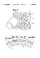
- FIG. 10shows an elevation view of another preferred roller portion of the present invention having irregular nap portions spaced apart to pick up and spread paint.
- FIG. 11shows an elevation view of another preferred roller portion of the present invention having irregular nap portions spaced apart to pick up and spread paint.
- FIG. 12shows a top view of an alternate embodiment of the bifurcated roller where three roller portions may be used.
- FIG. 13shows a masonry block having a rough surface paintable by the present bifurcated roller.
- FIG. 14shows a top view of an alternate embodiment of the present invention where paint is fed to the roller portions via paint tubes.
- FIG. 15shows a section view of an embodiment similar to FIG. 14.
- FIG. 16shows a section view of the internal hopper of one roller portion of FIG. 14, which may be used for spreading one color.
- FIG. 17shows an elevation view of the roller portion of FIG. 16.
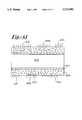
- FIG. 18shows a section view of another internal hopper arrangement where one roller portion may have two aligned hoppers, which may be used for spreading the same or different colors.
- FIG. 19shows an elevation view of the roller portion of FIG. 18.
- FIG. 20shows a section view of another internal hopper arrangement where one roller portion includes two nonaligned hoppers, which may be used for spreading the same of different colors.
- FIG. 21shows an elevation view of the roller portion of FIG. 20.
- FIG. 22shows a top view of a tray for the paint pan of FIG. 4, with the tray having a roughened surface for wiping excess paint off the roller of FIG. 1.
- FIG. 23shows a section view at lines 23--23 of FIG. 22.
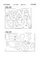
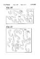
- FIGS. 24-37show irregular nap arrangements in dimensions close to actual size for being placed on the roller portions of the bifurcated roller; each nap arrangement is for one roller portion and an identical nap arrangement is placed on its adjacent but spaced apart roller.
- FIG. 38shows elevation and perspective views of elements of a kit for the present method.
- FIG. 39shows a schematic view of a three nozzle arrangement for simultaneously painting three colors.
- FIG. 40shows a schematic view of the nozzles of FIG. 39 in tracks, and further shows stencils set in the nozzles for delivering pulses of paint.
- FIG. 41shows a section view of a roller portion for rolling a pattern on masonry.
- the present bifurcated rolleris indicated in general by the reference numeral 10. It includes a frame arrangement 12 having a proximal end portion 14 having a handle or grip 16 affixed thereto and a distal end portion 18 having rotatably mounted thereto a pair of roller portions 20.
- the distal end portion 18is bifurcated and includes an open-ended slot 22.
- the distal end portion 18includes a pair of generally L-shaped metal rods 24 welded at a junction 26 and having an integral end 28 on which one roller portion 20 is mounted. If desired, each of the rods 24 may have one or more bends therein between the handle 14 and the roller portions 20.
- the roller portionshaving axes which are aligned with each other.
- a plastic roller mount 32is rotatably engaged to each of the rods or shafts 24 and is prevented from axial movement in one direction by a washer 34 fixed to each of the rods 24.
- An annulus 36 integral with and on each of the roller mounts 32prevents axial movement of its respective roller portion 20 toward the slot 22.
- Four bars 38 for further mounting one of the roller portions 20are fixed in and extend between the proximal disk like roller mount 32 and a respective distal plastic roller mount 40.
- Mount 40is similar to mount 32 except that mount 40 lacks the annulus 36 to permit the roller portion 20 to be slid onto the bars or cage 38. Ends of the bars 38 angle inwardly toward their respective mount 32 or 40.
- the roller portion 20includes a nap 42 affixed to a cylindrical base 44. As shown in FIG. 3, the bars 38 frictionally engage the base 44, thereby permitting proximal end portions 46 of the roller portions 20 to be adjusted to and away from each other, and to stay fixed at the adjusted position for painting. A preferred spread between the proximal end portions 46 falls in the range of between about two inches and about five inches.
- the nap 42may be fleece or mohair. The radial length of the nap 42 may fall in a range of between about 1/8 inches and 11/2 inches.
- an integrally molded paint receptacle or pan 50includes two outer sidewalls 52 and two end walls 53 forming two main receptacle portions 54 separated by a divider or interior wall 56.
- Interior wall 56includes a thickness less than the width of the slot 22 and the depth of the slot 22 is greater than the height of the interior wall 56 at the deep, curved portion 60 to permit the slot 22 to receive the interior wall 56 and to permit the roller portions 20 to be frilly dippable into the receptacle portions 60.
- a relatively deep receptacle portion 58, having a carved bottom 60 to reflect the curvature of the roller portions 20,extends between the sidewalls 52.
- the curved bottom 60serves as a first supporting end for the pan 50.
- the curved bottom 60leads into roughened floor portions 62, 64.
- Floor portion 62may include raised rib like portions 66 and floor portion 64 may include raised knobs or bumps 68.
- each of the floor portions 62, 64includes the same roughened surface, i.e., either the ribs or the knobs. However, for purposes of illustration, one floor portion is shown with ribs and the other floor portion is shown with knobs.
- the roller portions 20are rolled on the roughened floor portions 62, 64 to wipe off excess paint off the roller portions 20. Further, after being dipped into the deep portions 58, about one-half of each of the roller portions 20 may be weighted down with excess paint, and such an excess prevents the roller portions 20 from rolling. Rolling the roller portions 20 on the roughened surfaces 66 and 68 initiates such a rolling.
- a tray 70may be mounted on the sidewalls 52 and interior wall 56 for providing another roughened surface upon which the roller portions 20 may be rolled.
- the trayincludes a pair of legs 72 which snap or friction fit into recesses 74 formed in the sidewalls 52 and interior wall 56.
- the tray 70is integrally molded and includes channels 76 having holes 78.
- the channels 76form diamond shaped surfaces 80 having edges 82.
- a pair of receptacle portions 90are formed in the pan 50 adjacent to a second supporting end 92 of the pan 50.
- the receptacle portions 90are formed by relatively low interior end walls 94 and a relatively low dividing interior wall 96.
- Wall 94is relatively low to permit paint which is poured into one of the portions 90 to flow into its respective receptacle portion 54.
- Dividing wall 96is relatively low to permit a single brush to be dipped into both of the receptacle portions 90 at the same time and pick up paints having different colors, or different characteristics, at the same time.
- the method of the present inventionincludes choosing and cleaning the substrate to be painted.
- the substrateincludes sheet rock, pre-existing painted surfaces, wood walls and floors and cabinets, concrete walls and floors, and rock or stucco walls and floors or other surfaces.
- Decorative block 100 having a rough paintable surface 102is shown in FIG. 13 and is an example of a surface other than a flat wall or floor that may be painted with the bifurcated roller 10. Paint surface 102 preferably includes using a longer nap, on the order of 11/4 inches, and perhaps a greater amount of paint.
- the next step in the present methodis preferably the application of a base coat to the substrate.
- the base coatis preferably a latex (emulsion), acrylic-based, alkyd, oil-based, epoxy, chlorinated robber, Portland cement, paint for metal such as aluminum paint, or texture paint, and more preferably a water-based polyurethane.
- the base coatmay be applied with brushes, a conventional roller, air spray or airless guns, or the present bifurcated roller. After application of the base coat, the base coat is permitted to dry.
- the textured coatpreferably is a water-based polyurethane, acrylic-based, alkyd, oil-based, epoxy, chlorinated rubber, Portland cement, paint for metal such as aluminum paint, or texture paint, and more preferably a latex (emulsion) paint, having a thickening agent such as one or more of the thickening agents of calcium carbonate, clay, or aluminum hydrate.
- the textured coatmay be applied with brushes, a conventional roller, air spray or airless guns, or the present bifurcated roller. Substantially immediately after application of the textured coat and while the textured coat is still wet, sheeting is pressed on the textured coat.
- the sheetingis preferably plastic, and more preferably a polyethylene sheeting about one rail in thickness.
- sheetinginvariably and preferably includes folds, creases, and/or air pockets; such irregular application of the sheeting is preferred.
- the sheetingis pressed on and over the textured coat with hands, a conventional roller, or the present bifurcated roller.
- the sheetingis then removed while the textured coat is still wet. When removed, the sheeting itself removes some of the textured coat, which is stock to the underside of the sheeting. Removal of the sheeting leaves a variegated, somewhat rough topography to the textured coat.
- the next preferred stepis application of at least a two color coat, or two characteristic coat, with the present bifurcated roller 10.
- a stepmay directly follow the step of applying the base coat, or may directly follow the step of applying the texture coat and sheeting.
- the paints of this stepare preferably oil, latex, or epoxy, and more preferably a water-based polyurethane.
- the application of a water-based polyurethane by this stepsandwiches the preferred, though less durable textured latex coat, between two durable water-based polyurethane layers.
- This stepincludes the application of at least two paints or coatings, each having a different characteristic, and each applied by a different roller portion 20, each of which picks up the paint from a different receptacle portion 58.
- the coatingspreferred are adhesives, cleaning compounds, stripping compounds which have different characteristics which may be applied separately to a surface, and more preferably are paints having different characteristics.
- paintssuch different characteristics preferably include texture, kind (such as latex, oil, epoxy, or water-based polyurethane), or surface tension, and more preferably include color or shade.
- the different characteristicsincludes different micaceous paints, i.e. paints having pearlescent pigments.
- the surface tensions of the paints having at least one different characteristicPrior to being coated on either the base coat or textured coat, the surface tensions of the paints having at least one different characteristic are then equalized. Without equalizing the surface tension of the paints, one of the paints may run at a greater rate than the other paint; one of the paints will drip down or across the substrate.
- the surface tension of the paints or coatingsare equalized by adding thickening or thinning agents. Thickening agents include calcium carbonate, clay, or aluminum hydrate. Thinning agents include solvents or diluents such as hydrocarbons. It should be noted that as well as being equalized, the surface tension of the paints may be raised, such as to about 140 to 150 Krebs to provide a thicker two-paint coating.
- the paintsare poured into respective receptacles 58, or into respective receptacles 90 from which the paints may flow into their respective receptacles 58.
- the bifurcated roller 10is then dipped into pan 50 such that each of the roller portions 20 picks up paint from a different receptacle portion 58. Then the roller portions 20 are rolled on the roughened surfaces 66, 68 to wipe excess paint off the roller portions 20.
- Reference numbers 112, 114represent respective bands of paint left by the adjacent but separated roller portions 20.
- Reference number 116represents a portion where the bands 112, 114 have overlapped and intermixed. Portion 116 may have been formed by band 112 overlapping band 114 or vice versa.
- the process of rolling the adjacent but separated roller portions 20continues until the desired effect is formed on the substrate 110.
- the base or textured coatmay be partially or completely covered. It should be noted that as the roller 10 is turned, the outer roller portion 20 rotates at a faster rate than the inner roller portion 20; such an independent axis for each color characteristic advantageously provides for a greater random effect.
- a sheeting 120may be applied or pressed onto the two characteristic coating.
- the sheeting 120is preferably plastic, and more preferably a polyethylene sheeting about one rail in thickness.
- Such sheeting 120invariably and preferably includes folds, creases, and/or air pockets; such irregular application of the sheeting 120 is preferred.
- the sheeting 120is pressed on and over the two characteristic coating with hands, a conventional roller, or the present bifurcated roller. The sheeting 120 is then removed while the two characteristic coating is still wet. When removed, the sheeting 120 itself removes some of the two characteristic coating, which is stock to the underside of the sheeting 120.
- reference numerals 122represent some of the two characteristic coating which has been removed by the sheeting 120 to expose a portion 124 of the base or textured coating.
- Portions 126 on substrate 110represent areas where the bands 112, 114: 1) have not covered the base or textured coat or 2) have been rolled on the base or textured coat without overlapping another band or having been overlapped by another band or 3) have overlapped another band or have been overlapped or 4) have overlapped or have been overlapped more than once.
- step of applying a sheeting to the textured coatis substantially the same as the step of applying sheeting to the two characteristic coat. Such steps are represented in FIG. 7.
- the sheetingif a greater amount of coating, such as base coat, textured coat, or two characteristic coat, is to be removed, the sheeting is left on the underlying coat for a greater period of time to permit a greater amount of paint to dry and stick to the sheeting.
- Optional subsequent stepsmay be taken either directly after application of the two characteristic coat and the drying of such, or after the removal of the sheeting 120 and the drying of its variegated two characteristic coat.
- These optional stepsmay include the application of strings of paint, of paint spatters, or the application of gloss.
- Stringsare represented by reference numerals 128 and spatters by reference numerals 130.
- Variegationsare represented by reference numeral 124.
- the strings 128 and spatters 130may be applied by a spray gun 132.
- FIGS. 9A-Dshow different types of naps.
- Each of the napsincludes a cylindrical base 140.
- Reference number 142indicates a new nap where the fleece or hairs run in a wavy, parallel fashion. Paint absorption of nap 142 is relatively great. Paint is spread upon the substrate, rather than being thrown on the substrate. Nap 144 is matted; the fleece or hairs have become stuck together over time. Paint absorption of nap 144 is relatively small. Instead of being spread upon the substrate or underlying coat, paint is thrown upon the substrate. Such a throwing of paint is preferred.
- Nap 146includes flags or split hairs 148 which decrease the absorption potential of nap 146.
- Nap 152is similar to nap 146 in that it includes a layer 154 of little absorbency where the tips of the hairs have intertwined and/or become matted and a layer 156 of greater absorbency where the hairs lie parallel to each other.
- the parallel and/or wavy hair portions 150 and 156(and the hairs of nap 142) may act like capillaries which readily draw up and absorb paint.
- the matted, flagged, or intertwined portions 148 and 154 (and the hairs of nap 144)lack such capillaries, and may thus be less absorbent.
- FIGS. 10 and 11represent roller portions wherein the naps are comprised of nap portions.
- FIG. 10shows a roller portion 159 having a cylindrical base 160 for engaging the cage 38 and further having raised nap portions 162 formed of mohair approximately 1/4 inches in height. Mohair is a type of hog hair imported from China and is preferred for use with the present invention. Nap portions 162 have irregular peripheries.
- Roller portion 159may be paired with another roller portion having a layout identical to the nap portions 162, or with another roller portion having nap portions 162 of the same general shapes but laid out differently, or with a nap having a standard cylindrical shape as shown in FIG. 1, or with a roller portion having nap portions of a different shape.
- FIG. 11shows a roller portion 164 having a cylindrical base 166 for engaging the cage 38 and further having raised nap portions 168 formed of mohair approximately 1/4 inches in height. Nap portions 168 have irregular peripheries.
- roller portion 164may be paired with another roller portion having a layout identical to the nap portions 168, or with another roller portion having nap portions 168 of the same general shapes but laid out differently, or with a nap having a standard cylindrical shape as shown in FIG. 1, or with a roller portion having nap portions of a different shape such as roller portion 159.
- FIG. 12shows another roller embodiment 170 capable of mounting three spaced apart roller portions 20.
- the roller 170includes a frame arrangement having two axially aligned and spaced apart shafts 172, 174 and a third nonaligned shaft 176 upon which a roller portion 20 may be mounted with washers 34 and plastic mounts 32 and 40 or with washers 34 and the plastic bodies 206 noted below.
- Such a third roller portionmay contribute to the randomness of the desired end product.
- FIGS. 14-21illustrate other roller embodiments.
- FIG. 14shows a roller 180 having a set of three pressure-fed paint sticks or paint tubes 182 fixed in a planar arrangement via rigid belts 184.
- Each of the outer tubes 182includes an inner tube 186 with an end 188 for feeding paint or other coating 189 toward feed tubes 190 and roller portions 192.
- Inner tubes 186are pushed axially in the outer tubes 182 pneumatically through a manifold 194 communicating with an air source through a tube 196.
- Feed tubes 190are rigid so as to provide a frame arrangement for the roller portions 192 as well as to feed coating fluid to the roller portions 192.
- At each of the distal ends 197 of the feed tubes 190is affixed a swivel nozzle 198.
- Swivel nozzles 198are affixed in and rotate with a plastic body 206 which forms an internal hopper 202 which extends for 360° about the plastic body 206.
- Bearings or bushings 204 fixed in a cylindrical opening 207 of plastic bodyprovide support for the distal end portions 197 of the feed tubes 190.
- Nap 208may include a porous cylindrical base which supports the nap 208 and permits fluid flow therethrough.
- Hopper 202extends substantially to the ends of the roller portions 192 to wet the entire nap 208, as shown by the absence of phantom lines in FIG. 17.
- roller portion 210includes a plastic body 212 forming two internal hoppers 214, 216, each of which may feed a coating having the same or different characteristics to a respective, different nap portion 218, 220.
- the plastic body 212may form a linear junction between the hoppers 214 and 216, as shown by phantom line 222.
- the plastic bodymay form a nonlinear junction, such as a curvilinear junction 224 to provide a softer blend such as between two different colors.
- roller portion 230includes a plastic body 232 forming two internal hoppers 234 and 236, each of which may feed a coating having the same or different characteristics to a respective, different nap portion 238, 240.
- the plastic bodymay form an angled, linear junction 242 or a nonlinear, curved junction 244 between the hoppers 234, 236.
- internal hopperssuch as internal hoppers 202, 214, 216, 234, 236, may extend less than 360° about a roller portion.
- plastic bodies 206, 212, 232may form a hopper extending from 5° to 355° about a roller portion and have a periphery of any shape, such as an irregular shape shown in FIGS. 10, 11, and 24-37.
- FIG. 15shows the tubes 182, 186 in a more compact form. Such tubes are held together with two triangular rigid belts 250 disposed in the same location as belts 184.
- FIGS. 24-37illustrate nap arrangements.
- respective reference numerals 260a-nindicate respective nap portions and respective reference numerals 270a-n indicate the spacings between the nap portions 260a-n or the base to which the nap, most preferably mohair, is glued or otherwise affixed.
- the nap portions 260a-nmay be from about 1/8 inches to 1/4 inches to 1/2 inches in height. All nap portions 260a-n have their peripheries spaced from each of the other nap portions 260a-n.
- the arrangement of the nap portions 260a-nmay be in either the lateral or longitudinal direction of the roller portions 20.
- Each nap arrangementmay be manufactured in flat form with a flexible base which is later affixed to a rigid cylindrical base such as base 44.
- each nap arrangementmay be cut out of an already manufactured mohair cylindrical nap having a cylindrical base.
- Each nap arrangementmay fit on and around a roller portion 20 which preferably is about four inches in lateral length and includes a base diameter of about one to two inches.
- each nap arrangementis preferably paired with an identical nap arrangement.
- the pattern shown in FIG. 24may be the nap pattern for each of the roller portions of the bifurcated roller 10.
- similar nap patternsare placed on each of the roller portions.
- the nap arrangements of FIGS. 1, 10, 11, and 24-37may be mixed and matched with each other for placement on the roller portions of the bifurcated roller 10; for example, the nap arrangement of FIG. 36 may serve as one of the roller portions and the nap arrangement of FIG. 37 may serve as the other roller portion.
- each of the nap arrangementsspreads a paint of a different color characteristic.
- FIG. 24shows some nap portions 280 having irregular, general "U” or “V” shapes interdispersed with irregular, generally linear nap portions 282, irregular, generally diamond shaped nap portions 284, and irregular, generally triangular nap portions 286.
- the peripheries of the nap portions in FIG. 24generally have sharp corners and peripheries.
- FIG. 25shows a generally elephant foot or pond or lake pattern of nap portions 288 which generally have rounded peripheries.
- FIG. 26shows generally worm-like, endless nap portions 290 which are generally curvilinear.
- FIG. 27shows generally diamond, squared, rectangular, trapezoidal, and triangular shaped nap portions. Such nap portions are irregularly shaped and spaced from each other.
- FIG. 28shows nap portions which are irregular and generally formed in the shape of worms. Some nap portions have the irregular, general shape of a "U.”
- FIG. 29shows a mix of irregular, elongated nap portions and irregular, block like nap portions.
- FIG. 30shows nap portions shaped generally like the numbers “1", “2” and “3.” Such nap portions are irregularly shaped.
- FIG. 31shows nap portions shaped generally like wrought iron or musical clef symbols. Such nap portions are irregular and have curled ends.
- FIG. 32shows irregularly shaped linear nap portions.
- FIG. 33shows endless nap portions in the form of lips or smiles, block-like nap portions having curved peripheries, and nonlinear nap portion segments. Such nap portions are irregular.
- FIG. 34shows irregular, endless nap portions.
- One nap portionincludes a bridge 300.
- FIG. 35shows irregular nap portions generally in the form of blocks and worms.
- FIG. 36shows nap portions which when rolled may come the closest to duplicate the time consuming and expensive rag rolling painting method.
- the nap portionshere reflect the creases formed in a rolled rag.
- the arrangementgenerally includes elongate nap portion segments of a relatively great size and elongate nap portion segments of a relatively small size. Some of the peripheries are smooth; most of the peripheries are highly irregular with sharp turns.
- FIG. 37shows a general leaf or leaf-like pattern of irregular nap portions.
- a random method of paintingsuch as shown in FIG. 6, is preferably used for the nap patterns of FIGS. 10, 11, and 24-37.
- the bifurcated roller 10may be rolled in parallel fashion without the roller portions overlapping.
- the step of equalizing the paints or coatings having different characteristicsmeans adding one or more additives to one or more of the paints or coatings such as to make the paints or coatings compatible with each other, such as to make the viscosity or surface tension of the paints substantially the same, or such as to affect another feature of one or more of the paints so as to facilitate overlapping and intermixing.
- the paintsmay not intermix, which is preferred.
- the equalizing stepis preferred because the paints are wet at the same time on the substrate.
- the additivesinclude, but are not limited to, one or more of the following: thickening agents, thinning agents including solvents, antisettling agents, antiskinning agents, antifloating agents, driers to speed polymerization or oxidation or both such as the liquid or metallic soaps of cobalt, lead, manganese, or calcium, loss-of-dry inhibitors, freeze-thaw stabilizers, anti-foaming agents, preservatives, bodying and puffing agents (including thickening agents) which increase viscosity for proper application and drying, leveling agents to reduce brush or roller marks, antisagging agents to prevent curtains, runs or sags in wet paint, glossing and flatting agents to change the sheen of the paint, and coalescing agents to soften latex particles to help them flow into a continuous film.
- thickening agentsthinning agents including solvents, antisettling agents, antiskinning agents, antifloating agents, driers to speed polymerization or oxidation or both
- thickening agentsincluding solvent
- characteristicmeans a characteristic of the coating such as its pigment, color, extender, metallic extender, metal primer, extenders for flexibility or durability, vehicle, film-former such as an oil, resin, polymer, plasticizer, thinner, solvent, diluent, additive such as wetting agent, thickener, matting agent, accelerator, inhibitor, or dye, resin, natural resin, synthetic resin, any of the above mentioned additives for the equalizing step, adhesive, catalyst, or other chemical or agent serving a significant purpose in the coating or paint and whose generally simultaneous combination with another characteristic from an adjacent and spaced apart roller portion is desirable for the end product.
- film-formersuch as an oil, resin, polymer, plasticizer, thinner, solvent, diluent, additive such as wetting agent, thickener, matting agent, accelerator, inhibitor, or dye, resin, natural resin, synthetic resin, any of the above mentioned additives for the equalizing step, adhesive, catalyst, or other chemical or agent serving a significant purpose in the coating or paint and whose generally simultaneous combination with another characteristic from an adjacent and spaced
- characteristicmeans a "color characteristic.”
- a color characteristic for the purposes of the present applicationis defined as one of the following: color, hue, intermediate color, midtone, neutral, pastel, primary color, saturation, secondary color, shade, tertiary color, tint, tone, type of pearlescent paint, or type of micaceous material or other agent in the paint to achieve the pearlescent effect.
- a first hueis a color characteristic different from a second hue.
- the preferred features of the present inventionmay be mixed and matched to produce a certain combination or withheld to produce another combination.
- These preferred features, which may be present or absent in a combinationinclude but are not limited to the following: the bifurcated roller having spaced apart and axially aligned roller portions, a new, fleeced nap, a nap arrangement as shown in FIGS. 10, 11, and 24-37, a color characteristic, a matted, flagged, or intertwined nap for throwing paint which may be in the form of a cylindrical nap or a nap arrangement as in FIGS.
- a layer of textured painta layer of water-based polyurethane paint, a sandwich of water-based polyurethane/textured latex paint/water-based polyurethane, an axial adjustment of the spacing between the roller portions, the height of the nap hairs from the base of the nap, the sheeting applied to the textured coat, the sheeting applied to the two-color coat, the strings of paint, the spatters, a bifurcated roller having a roller portions with axes offset from one another, base coat, color of base coat, dividing wall in paint pan to separate paint for each roller portion, and pressure-fed rollers having internal hoppers.
- Substratesinclude but are not limited to interior and exterior surfaces such as acoustical, fiberboard, drywall, plaster, masonry, concrete, concrete block, unglazed brick, cement brick, concrete or masonry floors, aluminum, galvanized steel, structural steel and ornamental iron, wood walls, ceilings, trim cabinet works, hardboard, painted wood floors, stained wood floors, asbestos siding, transite, shingle, stucco, common brick, concrete walls, concrete and cinder block, concrete floors, patios, steps, platforms, ornamental steel, prefinished metal siding and panels, wood floors and platforms, plywood, shingles, shakes, rough-sawn lumber, siding, trim, doors, hardboard, and oriented strand board.
- interior and exterior surfacessuch as acoustical, fiberboard, drywall, plaster, masonry, concrete, concrete block, unglazed brick, cement brick, concrete or masonry floors, aluminum, galvanized steel, structural steel and ornamental iron, wood walls, ceilings, trim cabinet works, hardboard, painted wood floors, stained wood floors, asbestos siding, transite,
- Coatings and paintsinclude those mentioned above and further include but are not limited to acrylics, alkyds, chlorinated rubber, coal tar epoxies, epoxies, epoxy-esters, neoprene and hypalon, phenolics, phenolics catalyzed, polyesters, polyurethanes, silicones, vinyls, water-based coatings, and zinc-rich coatings.
- the roller nap or roller coversuch as nap 20, or nap portions such as indicated in FIGS. 10, 11, and 24-37 may be formed of synthetic or natural fibers.
- Synthetic fibersinclude open or closed foam.
- Natural fibersinclude mohair or wool.
- the foammay be a urethane foam.
- the napmay be formed of a rubber or plastic or wood with the nap pattern integrally formed therein.
- the present methodproduces the illusion or "faux air” that a substrate has been sponge painted or rag roll painted while in fact the substrate has been quickly painted with the present bifurcated roller.
- the present methoddelivers a coat of paint which is as thick as that applied by a conventional roller.
- a painter using the present bifurcated rollermay paint a bedroom sized room in an hour.
- a painter using a sponge or ragmay take one to three days to paint such a room.
- rag rollersproduce a great amount of waste; once the rag being rolled is saturated, a new rag is used.
- a pail or even a bushel or ragsmay be used.
- the naps having flagged or intertwined hairsmay be produced by taking a fleece nap, saturating the nap with paint, hand manipulating or pinching the nap into peaks and valleys, lightly washing off the nap with water, and then permitting the nap to dry.
- a fully matted napmay be prepared simply by using a nap over and over and over again with little washing of the nap.
- One type of polyethylene sheeting that may be used for producing the variegations in the textured coat and two-characteristic coatis Visquine®. It should be further noted that the variegations may be referred to as a marbling effect.
- tube 186 or paint in tube 182 of pressure-fed roller 180may, instead of being operated pneumatically, be pushed by hand, by a mechanism similar to a caulking gun, by an airless hydraulic mechanism, by a pressure paint pot, or by some other pump or compressing mechanism.
- the rate at which paint is fed to the internal hoppersmay be varied. For example, white paint may be fed at a faster rate than red paint in another tube. Such rates may be controlled by valves in the manifold.
- water-based polyurethane used hereinmay be cross-linked so as to be more durable.
- handling or rolling of the bifurcated roller 10produces varying effects. For example, more rolling produces more blending of colors and a greater percentage of the textured or base coat may be covered. More rolling generally produces a more conservative effect.
- the bifurcated roller 10may be of a smaller or miniature size to fit hard-to-reach areas. Conversely, the bifurcated roller 10 may be rather large, such as the roller used to paint the sides of buildings; in such a case it may be possible to produce random patterns which have different illusions from different distances. The scale of the patterns may be varied.
- extra defoamersuch as a water based silicone may be added so as to level out the paint being applied by the foam nap.
- One preferred kit combination 398includes a bifurcated roller 400 with a handle 402, a frame arrangement 404 having an open-ended slot 406 with a width greater than the thickness of dividing wall 408 of pan 410, which is similar to pan 50.
- the roller 400further includes roller portions 412 rotatably mounted on the frame arrangement 404.
- Each of the designer roller covers 412includes a pin type pattern which may provide a suede look when rolled.
- the pin type patternincludes raised nap portions 414 in the form of disks extending for 360° about each of the roller portions as each of the other nap patterns in FIGS. 10, 11 and 24-37.
- Reference numeral 416indicates the nonspreading base of the roller portion.
- the kit 398further includes a roller 418 for highlighting which includes a nap portion pattern or designer roller cover 420 as shown in FIG. 38 or as shown in FIGS. 10, 11, and 24-37.
- the roller 418includes a handle 422, a frame 424 affixed to the handle 422, and a roller portion 426 rotatably mounted on the distal end of the frame 424.
- the kit 398further includes brush 430 with a handle 432 and bristles 434 for interacting with receptacles 90.
- the kit 398further includes a corner roller 440 for rolling corners or intersections between walls.
- the roller 440includes a handle 442, a frame 444, and a generally disk like roller 446.
- the edge 447is formed by two beveled faces 448 extending at ninety degrees relative to each other and at forty-five degrees relative to faces 450 so as to roll in corners.
- Each of the faces 448have chunks of foam removed so as to leave crevices or openings 452 in the roller 446.
- the crevices 452carry the randomness effect of the paint into the corner of the room where the roller 10 may not reach.
- the kit 398further includes a set 460 of cylindrical roller covers.
- the set 460includes a pair of roller covers 462 with one roller cover being a cylindrical conventional nap portion as shown in FIG. 1 and with the other roller cover having a pattern in the nature of the pattern shown in FIG.
- the kit 398further includes the pan 410, and a set 470 of four liners 472.
- Each liner 472fits into one of the receptacle portions 54; hence each liner 472 holds only one color.
- Each liner 472is integrally molded and conforms generally if not substantially perfectly to the inner contour of one half of pan 410 or pan 50.
- two or more colors or characteristicsmay be applied to a substrate 500 simultaneously with a spray gun having three nozzles 502, 504, 506 which are fed paint independently of each of the other nozzles.
- Each of the nozzles 502, 504, 506has a respective stencil 508, 510, 512 fixed therein to deliver paint in the form of a square 514, triangle 516, or circle 518 to the substrate 500.
- a middle portion of each stencilmay be supported by an integral support 520.
- Each of the nozzles 502, 504, 506may deliver the paint in a pulsating manner while a rigid portion 522 of each of the nozzles is moved in a respective track 540, 550, 560 formed in a plate 570.
- a less rigid portion 580 of each of the nozzlesmay extend to conventional paint pumping equipment.
- Such pumping equipmentmay be that which delivers strings or spatters to walls.
- the patternmay be wiped with brushes manually or automatically or may have impressed upon it sheeting as described above.
- the polyethylene sheetingmay be applied manually or automatically, pressed manually or automatically upon the substrate, and removed before the paint is dry to form variegations.
- the designer roller covers or nap arrangementsmay be customized so as to reflect the pattern of a curtain or carpet that one wishes to duplicate.
- the pattern found in the carpetis reproduced for both roller portions, and the color or colors of the carpet are spread separately and simultaneously by the spaced apart but adjacent roller portions.
- FIG. 42shows in section a roller cover 600 for rolling patterns on stucco or other masonry.
- the roller cover 600includes a cylindrical base 602, a closed or open celled foam 604 in cylindrical form affixed to the base 602, and nap portions 606, 608, 610, 612, 614, and 616 fixed to the foam 604.
- the hairs of the nap portions 606-616may be individually set in the foam 604 or each of the pattern forming nap portions may include a base 620 which is affixed to the foam and in which each of the hairs is set.
- the foamconforms to the relative rough and deep topography of masonry, such as stucco, and delivers paint into valleys formed in the masonry.
- the hairs of the cover 600may be relatively long if desired.
- the base colormay be one of the colors applied by one of the roller portions 20 or by any of the designer covers of FIGS. 10, 11, and FIGS. 24-38.
- each of the nap arrangements or designer covers of FIGS. 10, 11, and FIGS. 24-38may be referred to as stencil covers.
- the two color or two characteristic coatmay be dry brushed such as with brush 430. Such may tone down the end effect.
- faux finishesare not durable. Neither is wallpaper durable.
- a "faux” lookcan be provided, and such a “faux” look is durable, especially when cross-linked polyurethane paint is used.
- the present methodprovides a "faux” look which can be washed, driven upon by cars, scratched and repaired. Such is not possible with wallpaper or the delicate "faux” works provided by sponge painting or rag rolling.
- stencilsmay be used with the bifurcated roller 10. Such stencils may be formed of the thin polyethylene sheeting, and the bifurcated roller 10 may be rolled over such a stencil and over the gaps formed in the stencil.
- the following aesthetically pleasing sampleswere obtained with the present bifurcated roller.
- the examplesincluded the following features: a plywood panel as a substrate, a water-based polyurethane base coat which was applied over 100% of the face of the substrate, and a water-based polyurethane base coat for each of the two colors in the two color coat.
- Relatively less durable latex paintwas used for the intermediate textured coat.
- Mixed in with the latex paint for the intermediate coatwere one or more of the following fillers: calcium carbonate, clay, aluminum hydrate.
- the rollerswere spread apart by about three inches, unless otherwise noted.
- Type of bifurcated rollerFleece, matted to throw paint
- Type of bifurcated rollerFleece, matted to throw paint
- Length of naps on bifurcated roller11/4 inches when new, about 3/4 inches when matted
- Sheeting applied over two color coatYes, removed to take off about 50% of two color coat
- Optional stepsOrange pearl glaze highlighting with conventional roller after two-color coat applied, prior to application of sheeting.
- Type of bifurcated rollerIrregular pattern, foam, used (less absorbent)
- Type of bifurcated rollerMohair, elephant foot random pattern
- Type of bifurcated rollerFoam pad having diamond shapes, spaced irregularly, with rollers separated by four inches
- Type of bifurcated rollerStrips of foam laid parallel to axis of roller, irregularly spaced
- Type of bifurcated rollerFleece, matted; roller portions spread by five inches
- Length of naps on bifurcated roller11/4 inches when new, 3/4 inches when matted
- Type of bifurcated rollerFoam with two inch long scores cut therein
- Green pearl glazeTwo color coat: Green pearl glaze, rust pearl glaze
Landscapes
- Engineering & Computer Science (AREA)
- Mechanical Engineering (AREA)
- Application Of Or Painting With Fluid Materials (AREA)
- Coating Apparatus (AREA)
- Soil Working Implements (AREA)
- Fixing For Electrophotography (AREA)
Abstract
Description
Claims (25)
Priority Applications (9)
| Application Number | Priority Date | Filing Date | Title |
|---|---|---|---|
| US08/655,408US5713095A (en) | 1996-05-30 | 1996-05-30 | Bifurcated paint roller and painting method |
| AU31518/97AAU722031B2 (en) | 1996-05-30 | 1997-05-29 | Bifurcated paint roller and painting method |
| NZ332956ANZ332956A (en) | 1996-05-30 | 1997-05-29 | Paint roller with two co-linear rollers, capable of applying two different colours simultaneously |
| BR9709481-1ABR9709481A (en) | 1996-05-30 | 1997-05-29 | Bifurcated paint roller and method for painting |
| PCT/US1997/009416WO1997045204A2 (en) | 1996-05-30 | 1997-05-29 | Bifurcated paint roller and painting method |
| CA002255878ACA2255878C (en) | 1996-05-30 | 1997-05-29 | Bifurcated paint roller and painting method |
| EP97926851AEP0901409A4 (en) | 1996-05-30 | 1997-05-29 | Bifurcated paint roller and painting method |
| US09/005,301US6022588A (en) | 1996-05-30 | 1998-01-11 | Method for painting with hand tool having bifurcated roller portions |
| US09/010,271US5983437A (en) | 1996-05-30 | 1998-01-21 | Bifurcated paint roller and painting method |
Applications Claiming Priority (1)
| Application Number | Priority Date | Filing Date | Title |
|---|---|---|---|
| US08/655,408US5713095A (en) | 1996-05-30 | 1996-05-30 | Bifurcated paint roller and painting method |
Related Child Applications (2)
| Application Number | Title | Priority Date | Filing Date |
|---|---|---|---|
| US09/005,301ContinuationUS6022588A (en) | 1996-05-30 | 1998-01-11 | Method for painting with hand tool having bifurcated roller portions |
| US09/010,271Continuation-In-PartUS5983437A (en) | 1996-05-30 | 1998-01-21 | Bifurcated paint roller and painting method |
Publications (1)
| Publication Number | Publication Date |
|---|---|
| US5713095Atrue US5713095A (en) | 1998-02-03 |
Family
ID=24628763
Family Applications (3)
| Application Number | Title | Priority Date | Filing Date |
|---|---|---|---|
| US08/655,408Expired - Fee RelatedUS5713095A (en) | 1996-05-30 | 1996-05-30 | Bifurcated paint roller and painting method |
| US09/005,301Expired - Fee RelatedUS6022588A (en) | 1996-05-30 | 1998-01-11 | Method for painting with hand tool having bifurcated roller portions |
| US09/010,271Expired - Fee RelatedUS5983437A (en) | 1996-05-30 | 1998-01-21 | Bifurcated paint roller and painting method |
Family Applications After (2)
| Application Number | Title | Priority Date | Filing Date |
|---|---|---|---|
| US09/005,301Expired - Fee RelatedUS6022588A (en) | 1996-05-30 | 1998-01-11 | Method for painting with hand tool having bifurcated roller portions |
| US09/010,271Expired - Fee RelatedUS5983437A (en) | 1996-05-30 | 1998-01-21 | Bifurcated paint roller and painting method |
Country Status (7)
| Country | Link |
|---|---|
| US (3) | US5713095A (en) |
| EP (1) | EP0901409A4 (en) |
| AU (1) | AU722031B2 (en) |
| BR (1) | BR9709481A (en) |
| CA (1) | CA2255878C (en) |
| NZ (1) | NZ332956A (en) |
| WO (1) | WO1997045204A2 (en) |
Cited By (41)
| Publication number | Priority date | Publication date | Assignee | Title |
|---|---|---|---|---|
| WO1999039836A1 (en) | 1998-02-05 | 1999-08-12 | Wagner Spray Tech Corporation | Bifurcated roller with paint tray divider receiver and integral frame |
| US5956802A (en)* | 1997-04-11 | 1999-09-28 | Wagner Spray Tech Corporation | Painting apparatus and assembly |
| US5966772A (en)* | 1997-11-10 | 1999-10-19 | Newell Operating Co. | Paint supply and finishing system |
| US5980802A (en)* | 1997-04-11 | 1999-11-09 | Wagner Spray Tech Corporation | Method for treating paint roller covers |
| US5983437A (en)* | 1996-05-30 | 1999-11-16 | Wagner Spray Tech Corporation | Bifurcated paint roller and painting method |
| US6013110A (en)* | 1998-11-03 | 2000-01-11 | Gee; Jenipher T. | Methods of pattern dyeing hair with a hair dye retaining roller |
| US6012198A (en)* | 1997-04-11 | 2000-01-11 | Wagner Spray Tech Corporation | Painting apparatus |
| EP0979684A2 (en) | 1998-08-13 | 2000-02-16 | Padco, Inc. | Paint system |
| WO2000020125A1 (en)* | 1998-10-02 | 2000-04-13 | Wagner Spray Tech Corporation | Faux finish applicator and method |
| WO2000020126A1 (en)* | 1998-10-02 | 2000-04-13 | Wagner Spray Tech Corporation | Decorative surface treatment apparatus and method |
| WO2000038842A1 (en)* | 1998-12-23 | 2000-07-06 | Wagner Spray Tech Corporation | Paint applicator with long-napped wool covered rollers and painting method |
| US6101658A (en)* | 1997-11-10 | 2000-08-15 | Newell Operating Company | Liquid coating applicator having spaced applicating mediums |
| US6117494A (en)* | 1997-04-11 | 2000-09-12 | Wagner Spray Tech Corporation | Paint roller method and apparatus |
| US6125530A (en)* | 1999-01-05 | 2000-10-03 | Lucent Technologies, Inc. | Method and apparatus for handling laser bar |
| US6203309B1 (en)* | 1998-08-10 | 2001-03-20 | Wagner Spray Tech Corporation | Apparatus for embossing paint rollers |
| US6240588B1 (en)* | 1999-12-03 | 2001-06-05 | Lam Research Corporation | Wafer scrubbing brush core |
| USD447874S1 (en) | 2000-01-29 | 2001-09-18 | Robert D. Newman | Tool handle |
| US6305045B1 (en) | 1999-07-08 | 2001-10-23 | Newell Operating Company | Paint supply and finishing system |
| USD463135S1 (en) | 2000-10-19 | 2002-09-24 | Susan Goans Driggers | Roller cover |
| US6532617B2 (en) | 2001-04-26 | 2003-03-18 | Plaid Enterprises, Inc. | Device for loading and maintaining two separate colors of paint on a paintbrush and method of using same |
| US6764715B2 (en)* | 2002-07-29 | 2004-07-20 | Robert Ives Janssen | Spatter painting |
| US20050034261A1 (en)* | 1999-06-25 | 2005-02-17 | Capoccia John S. | Paint roller and kit |
| US20050042382A1 (en)* | 2001-09-14 | 2005-02-24 | Palfrey Philip James | Method for roller-coating rough surfaces |
| US20050147761A1 (en)* | 2004-01-02 | 2005-07-07 | Richard Parks | Dual component dispensing and mixing systems for marine and military paints |
| US20070082180A1 (en)* | 2005-10-10 | 2007-04-12 | King Daniel W | System and method for making decorative building panels having a variegated appearance |
| US20070143946A1 (en)* | 2005-12-27 | 2007-06-28 | Song Kim | Multi paint roller connector |
| US20080072385A1 (en)* | 2006-09-27 | 2008-03-27 | Fellinger Thomas J | Extendable rotary scrubber |
| US20080081752A1 (en)* | 2006-09-27 | 2008-04-03 | Fellinger Thomas J | Roller for a rotary scrubber |
| US20080083078A1 (en)* | 2006-09-27 | 2008-04-10 | Fellinger Thomas J | Variable-length roller assembly for a rotary scrubber |
| USD578260S1 (en) | 2006-09-27 | 2008-10-07 | Johns Manville | Rotary scrubber roller |
| US7806612B1 (en) | 2006-12-05 | 2010-10-05 | Wangler William D | Device for applying fluids to convex surfaces |
| US20110099741A1 (en)* | 2009-10-29 | 2011-05-05 | Jose Antonio Gallardo | Combination paint roller, paint tray and stencil tube |
| US20110163104A1 (en)* | 2008-09-23 | 2011-07-07 | Hagen Lynn J | Multi-purpose bucket, particularly for painting |
| USD655919S1 (en)* | 2011-04-18 | 2012-03-20 | Howard Daley | Dual baluster stain-paint roller |
| US8726449B2 (en) | 2012-07-12 | 2014-05-20 | Arigala Painting, Inc. | Adjustable length paint roller |
| US8832897B2 (en) | 2009-10-29 | 2014-09-16 | Arigala Painting, Inc. | Dual-roller paint roller |
| USD862186S1 (en)* | 2017-11-28 | 2019-10-08 | Huber Engineered Woods, Llc | Compression roller |
| DE102022124083A1 (en)* | 2022-09-20 | 2024-03-21 | Bayerische Motoren Werke Aktiengesellschaft | Device for applying an adhesive to a contoured surface of a vehicle part and vehicle |
| USD1029507S1 (en) | 2023-10-13 | 2024-06-04 | Paul Mirmina | Paint roller |
| US12134106B2 (en) | 2021-11-22 | 2024-11-05 | Barbara Puzycki | Liquid applicator apparatus and associated method of using the same |
| US20250249703A1 (en)* | 2024-02-07 | 2025-08-07 | Joseph F. HEISLER, III | Receptacle for paint roller |
Families Citing this family (18)
| Publication number | Priority date | Publication date | Assignee | Title |
|---|---|---|---|---|
| US6675429B2 (en) | 2001-01-05 | 2004-01-13 | Polymer Group, Inc. | Imaged nonwoven fabric for imparting an improved aesthetic texture to surfaces |
| US6843177B2 (en)* | 2001-09-14 | 2005-01-18 | Fine Arts Group Llc | Methods and materials for producing an image, and articles comprising materials for producing an image |
| US6996872B2 (en)* | 2001-10-02 | 2006-02-14 | The Wooster Brush Company | Molded plastic paint roller tray |
| US20040159977A1 (en)* | 2003-02-18 | 2004-08-19 | Perfetto Robert S. | Method and apparatus for applying a decorative pattern to a surface |
| US20070178243A1 (en)* | 2006-01-30 | 2007-08-02 | Roman Decorating Products | Water-based faux finish and methods |
| US9204701B2 (en)* | 2006-03-20 | 2015-12-08 | American Medical Corporation | Daneshvar differential hair coloring and methods |
| US20080098688A1 (en)* | 2006-10-31 | 2008-05-01 | Gauthier Steven W | Devices for customizing window and door surrounds and method |
| US7451518B1 (en)* | 2007-08-22 | 2008-11-18 | Angelo Koumarianos | Multi-roller applicator for painting |
| EP2058139A1 (en)* | 2007-11-09 | 2009-05-13 | Van Wijhe Verf B.V. | Latent-energy heat control of paint viscosity |
| US8109227B2 (en)* | 2008-04-04 | 2012-02-07 | Belanger, Inc. | Automotive tire dressing applicator including cylindrical foam rollers with incremental rotation |
| US20110031668A1 (en)* | 2009-08-10 | 2011-02-10 | Raytheon Company | Vibration Isolation System |
| US8795808B2 (en) | 2011-06-01 | 2014-08-05 | Saint-Gobain Adfors Canada, Ltd. | Multi-directional reinforcing drywall tape |
| US9539608B2 (en)* | 2013-03-15 | 2017-01-10 | John A. Kenney | Paint roller |
| CN103615100B (en)* | 2013-11-08 | 2016-05-25 | 长兴诺英五金工具有限公司 | Rendering roller |
| BR112018075724B1 (en) | 2016-06-15 | 2022-04-05 | Bemis Company, Inc | Heat-seal lid with non-heat-seal layer and hydrophobic wrap |
| US11225797B2 (en)* | 2018-06-04 | 2022-01-18 | Everhard Products, Inc. | Roller for applying a sheet or membrane to a generally vertical surface |
| CN109332108A (en)* | 2018-12-17 | 2019-02-15 | 安徽宝泰特种材料有限公司 | A kind of simple painting device |
| US11407011B2 (en) | 2019-12-27 | 2022-08-09 | Randy Shoptaugh | Paint roller debris deposit pad |
Citations (29)
| Publication number | Priority date | Publication date | Assignee | Title |
|---|---|---|---|---|
| US2321511A (en)* | 1942-08-12 | 1943-06-08 | Piercy William | Paint applying device |
| US2693893A (en)* | 1953-04-01 | 1954-11-09 | Francis T Rice | Tool for use in resurfacing room enclosures |
| US2799884A (en)* | 1952-10-31 | 1957-07-23 | Gorman L Bedford | Paint applying device |
| US2838781A (en)* | 1954-03-29 | 1958-06-17 | Sherwin Williams Co | Multiple color paint tray |
| US2881461A (en)* | 1956-10-29 | 1959-04-14 | Wynton E Parker | Paint roller for curved surfaces |
| US2909797A (en)* | 1957-09-17 | 1959-10-27 | Edgar F White | Combined paint brush and roller trays |
| US3554659A (en)* | 1968-03-22 | 1971-01-12 | Roy E Stokes | Paint applicator roll with internal paint supply |
| US3562837A (en)* | 1968-11-25 | 1971-02-16 | Stanley W Baginski | Paint roller |
| US3609049A (en)* | 1968-11-22 | 1971-09-28 | Brush Co Ltd | Hand shampoo and supply tray |
| US3649986A (en)* | 1969-12-09 | 1972-03-21 | Walter Dahlund | Dual paint roller applicator |
| US3745624A (en)* | 1972-01-27 | 1973-07-17 | R Newman | Extensible paint roller frame |
| US3970396A (en)* | 1975-06-18 | 1976-07-20 | Brady William J | Paint applicator |
| US4164299A (en)* | 1977-10-14 | 1979-08-14 | Fuhr Patti S | Tray for paint and brushes |
| US4191792A (en)* | 1978-10-30 | 1980-03-04 | Padco, Inc. | Paint roller |
| US4257140A (en)* | 1978-04-28 | 1981-03-24 | Imperial Chemical Industries Limited | Painting device |
| US4434521A (en)* | 1982-06-30 | 1984-03-06 | Ppg Industries, Inc. | Applicator for applying a coating to a surface |
| US4467509A (en)* | 1982-09-23 | 1984-08-28 | Vittorio Dezen | Paint roller |
| US4897893A (en)* | 1989-04-19 | 1990-02-06 | The Wooster Brush Company | Paint roller frame including snap-on cover for outboard end cap |
| US4937909A (en)* | 1986-02-10 | 1990-07-03 | Georgiou Rogiros P | Roller structure for use in a paint roller, and paint roller incorporating the same |
| NL9002017A (en)* | 1989-09-15 | 1991-04-02 | Tollens S A | PAINT ROLL AND METHOD FOR USING IT. |
| US5117529A (en)* | 1989-07-05 | 1992-06-02 | Yugen Kaisha Ohta Kogyo | Combination roller and combination painting method using the combination roller |
| US5167055A (en)* | 1991-11-25 | 1992-12-01 | Bestt Rollr, Inc. | End cap for paint roller frame |
| US5178274A (en)* | 1991-11-14 | 1993-01-12 | Long Noal E | Holder-container for paint roller |
| USD332512S (en) | 1990-03-12 | 1993-01-12 | Bernard Aaron L | Paint pan with brush dock and paint reservoir |
| US5206979A (en)* | 1992-04-07 | 1993-05-04 | Campbell David W | Roller for specialty paint finishes |
| US5386611A (en)* | 1993-12-20 | 1995-02-07 | Kim; Ho C. | Paint roller |
| US5437593A (en)* | 1994-01-24 | 1995-08-01 | Gustavsen; Willard | Roller for planar flooring |
| US5471703A (en)* | 1994-05-16 | 1995-12-05 | Home E Z Products, Inc. | Apparatus for applying paint |
| US5511279A (en)* | 1994-08-29 | 1996-04-30 | Ippolito; Nicholas W. | Stackable paint roller pan having an integral paint reservoir, a paint roller parking device for a roller with extended handle, and an adjustable one-hand carrying handle |
Family Cites Families (58)
| Publication number | Priority date | Publication date | Assignee | Title |
|---|---|---|---|---|
| US29311A (en)* | 1860-07-24 | Straw-cutter | ||
| CA476613A (en)* | 1951-08-28 | Larry Altman | Self feeding paint roller devices | |
| US2735128A (en)* | 1956-02-21 | adams | ||
| DE330918C (en)* | 1920-12-24 | Paul J Paetzold | Wall sampling device | |
| US1084609A (en)* | 1912-02-07 | 1914-01-20 | Alexander M Clark | Liquid-container. |
| US1573594A (en)* | 1925-01-31 | 1926-02-16 | Winkenbach Konrad | Graining tool |
| CH191483A (en)* | 1936-07-01 | 1937-06-30 | Rueegg Edwin | Roller for pressing wallpaper. |
| US2371948A (en)* | 1943-06-23 | 1945-03-20 | Moore Benjamin & Co | Paint applying device |
| US2402346A (en)* | 1943-12-14 | 1946-06-18 | Harald T C Rosenlund | Stencil set |
| US2467010A (en)* | 1947-01-13 | 1949-04-12 | Leonard W Coley | Liquid coating applicator |
| US2630592A (en)* | 1951-03-28 | 1953-03-10 | Sultanik Leib | Paint applying device |
| US2680873A (en)* | 1951-11-23 | 1954-06-15 | Carl J Ernst | Paint roller |
| US2652774A (en)* | 1952-09-26 | 1953-09-22 | Decorola Corp | Coating device |
| US2753641A (en)* | 1954-03-26 | 1956-07-10 | Charles R Dorman | Decorating implement |
| US2955309A (en)* | 1958-04-14 | 1960-10-11 | Jr Arthur K Brown | Self-wringing floor cleaning and waxing device |
| US3102327A (en)* | 1961-05-24 | 1963-09-03 | Wooster Brush Co | Paint roller frame |
| US3711887A (en)* | 1971-09-30 | 1973-01-23 | Arsco Paint Rollers Inc | Paint roller and bearing assembly |
| SE370902B (en)* | 1972-07-10 | 1974-11-04 | J Andersson | |
| USRE29311E (en) | 1973-01-11 | 1977-07-19 | Painting apparatus | |
| US4007071A (en)* | 1974-05-31 | 1977-02-08 | Armstrong Cork Company | Process for making embossed needle-bonded fabric wall coverings |
| US4010866A (en)* | 1974-09-16 | 1977-03-08 | Impact Manufacturing Co., Inc. | Paint roller pan |
| US3986226A (en)* | 1974-11-04 | 1976-10-19 | The Wooster Brush Company | Roller cover support for paint roller frame |
| US4029011A (en)* | 1975-05-16 | 1977-06-14 | Ebbert Franklin Kurner | Multi color wells process |
| US3955260A (en)* | 1975-07-16 | 1976-05-11 | Sherden Herbert O | Applicator for ceiling texture material |
| US4000537A (en)* | 1975-10-23 | 1977-01-04 | Yen Kong Woo | Paint roller device having juxta-posed rollers |
| US4201801A (en)* | 1976-05-12 | 1980-05-06 | Nippon Paint Co., Ltd. | Method of forming a decorative relief pattern |
| US4102468A (en)* | 1976-12-16 | 1978-07-25 | Robert Ivan Goldman | Stackable paint tray |
| USD248335S (en) | 1977-03-21 | 1978-06-27 | Padco, Inc. | Paint pad bucket |
| SU694228A1 (en)* | 1978-05-22 | 1979-10-30 | Е. П. Любимов | Apparatus for painting products |
| CA1126213A (en)* | 1979-10-26 | 1982-06-22 | Edward J. Ridge | Fence picket roller painter |
| FR2489175A1 (en)* | 1980-09-04 | 1982-03-05 | Pechon Sa Ets Joseph | Cylindrical painting roller with handle - has oblique surface grooves joining into annular ones formed in periphery |
| US4492238A (en)* | 1981-09-30 | 1985-01-08 | Philip Morris Incorporated | Method and apparatus for production of smoke filter components |
| US4404703A (en)* | 1982-04-30 | 1983-09-20 | Collins & Aikman Corporation | Paint roller |
| USD286458S (en) | 1983-01-11 | 1986-10-28 | Juan Pages | Paint tray for corrugated roller type applicator |
| US4473609A (en)* | 1983-10-17 | 1984-09-25 | Armstrong World Industries, Inc. | Colored embossed needle-bonded fabric wall coverings and method of manufacture |
| GB2172820A (en)* | 1985-03-14 | 1986-10-01 | Alan David France | Paint roller |
| US4630952A (en)* | 1985-04-29 | 1986-12-23 | Saul Elbaum | Design painting device with stability and independent drive |
| DE3616114A1 (en)* | 1986-05-13 | 1987-11-19 | Arthur Schneider | Device for applying paints and liquids simultaneously to more than one plane |
| DE3875024T2 (en)* | 1987-08-05 | 1993-03-04 | Ici Plc | PAINTING TOOL. |
| US4919975A (en)* | 1987-12-03 | 1990-04-24 | Bpmf, Inc. | Method of producing a painted marbleized finish on an exposed surface |
| US4872236A (en)* | 1988-06-24 | 1989-10-10 | Thompson Marshall A | Corner painting attachment for paint rollers |
| USD327755S (en) | 1989-11-14 | 1992-07-07 | Boyer Jerry D | Combined paint roller tray and cover therefor |
| US5139139A (en)* | 1990-02-23 | 1992-08-18 | Alco Industries, Inc. | Paint tray |
| US5169022A (en)* | 1990-03-01 | 1992-12-08 | Elliott Raymond W | Circular paint tray |
| EP0507028A1 (en)* | 1991-04-04 | 1992-10-07 | Malden Mills Industries, Inc. | Treating velvet-like fabric |
| WO1993008929A1 (en)* | 1991-10-30 | 1993-05-13 | New Tech Industrial Products, Inc. | Multiple effect applicator and method |
| US5325958A (en)* | 1993-02-04 | 1994-07-05 | Western Publishing Co., Inc. | Combination paint tray and storage box |
| WO1995026304A1 (en)* | 1994-03-28 | 1995-10-05 | Greg Wawrzyniak | Forearm supported tray |
| US5412832A (en)* | 1994-04-06 | 1995-05-09 | Irven; Neil | Edging paint roller |
| US5533228A (en)* | 1994-08-29 | 1996-07-09 | Newell Operating Company | Resealble paint tray |
| US5473791A (en)* | 1994-09-22 | 1995-12-12 | Holcomb; Tim C. | Paint roller and tray apparatus |
| US5493751A (en)* | 1994-11-04 | 1996-02-27 | Misiukowiec; Daniel | Versatile paint pan |
| US5611100A (en)* | 1995-04-03 | 1997-03-18 | Zigelboim; Ilan | Paint roller |
| US5539948A (en)* | 1995-04-10 | 1996-07-30 | Mccauley; Pat | Paint roller cleaning adapter |
| US5509169A (en)* | 1995-05-24 | 1996-04-23 | Drucker; Mel | Paint tray with paint brush holder |
| US5693141A (en)* | 1995-07-21 | 1997-12-02 | Tramont; Thomas J. | Special effect paint roller |
| US5577291A (en)* | 1996-01-02 | 1996-11-26 | Myers; Micheal J. | Decorative paint roller device |
| US5713095A (en)* | 1996-05-30 | 1998-02-03 | Incredicoat, Inc. | Bifurcated paint roller and painting method |
- 1996
- 1996-05-30USUS08/655,408patent/US5713095A/ennot_activeExpired - Fee Related
- 1997
- 1997-05-29WOPCT/US1997/009416patent/WO1997045204A2/ennot_activeApplication Discontinuation
- 1997-05-29AUAU31518/97Apatent/AU722031B2/ennot_activeCeased
- 1997-05-29NZNZ332956Apatent/NZ332956A/enunknown
- 1997-05-29EPEP97926851Apatent/EP0901409A4/ennot_activeWithdrawn
- 1997-05-29BRBR9709481-1Apatent/BR9709481A/enactiveSearch and Examination
- 1997-05-29CACA002255878Apatent/CA2255878C/ennot_activeExpired - Fee Related
- 1998
- 1998-01-11USUS09/005,301patent/US6022588A/ennot_activeExpired - Fee Related
- 1998-01-21USUS09/010,271patent/US5983437A/ennot_activeExpired - Fee Related
Patent Citations (29)
| Publication number | Priority date | Publication date | Assignee | Title |
|---|---|---|---|---|
| US2321511A (en)* | 1942-08-12 | 1943-06-08 | Piercy William | Paint applying device |
| US2799884A (en)* | 1952-10-31 | 1957-07-23 | Gorman L Bedford | Paint applying device |
| US2693893A (en)* | 1953-04-01 | 1954-11-09 | Francis T Rice | Tool for use in resurfacing room enclosures |
| US2838781A (en)* | 1954-03-29 | 1958-06-17 | Sherwin Williams Co | Multiple color paint tray |
| US2881461A (en)* | 1956-10-29 | 1959-04-14 | Wynton E Parker | Paint roller for curved surfaces |
| US2909797A (en)* | 1957-09-17 | 1959-10-27 | Edgar F White | Combined paint brush and roller trays |
| US3554659A (en)* | 1968-03-22 | 1971-01-12 | Roy E Stokes | Paint applicator roll with internal paint supply |
| US3609049A (en)* | 1968-11-22 | 1971-09-28 | Brush Co Ltd | Hand shampoo and supply tray |
| US3562837A (en)* | 1968-11-25 | 1971-02-16 | Stanley W Baginski | Paint roller |
| US3649986A (en)* | 1969-12-09 | 1972-03-21 | Walter Dahlund | Dual paint roller applicator |
| US3745624A (en)* | 1972-01-27 | 1973-07-17 | R Newman | Extensible paint roller frame |
| US3970396A (en)* | 1975-06-18 | 1976-07-20 | Brady William J | Paint applicator |
| US4164299A (en)* | 1977-10-14 | 1979-08-14 | Fuhr Patti S | Tray for paint and brushes |
| US4257140A (en)* | 1978-04-28 | 1981-03-24 | Imperial Chemical Industries Limited | Painting device |
| US4191792A (en)* | 1978-10-30 | 1980-03-04 | Padco, Inc. | Paint roller |
| US4434521A (en)* | 1982-06-30 | 1984-03-06 | Ppg Industries, Inc. | Applicator for applying a coating to a surface |
| US4467509A (en)* | 1982-09-23 | 1984-08-28 | Vittorio Dezen | Paint roller |
| US4937909A (en)* | 1986-02-10 | 1990-07-03 | Georgiou Rogiros P | Roller structure for use in a paint roller, and paint roller incorporating the same |
| US4897893A (en)* | 1989-04-19 | 1990-02-06 | The Wooster Brush Company | Paint roller frame including snap-on cover for outboard end cap |
| US5117529A (en)* | 1989-07-05 | 1992-06-02 | Yugen Kaisha Ohta Kogyo | Combination roller and combination painting method using the combination roller |
| NL9002017A (en)* | 1989-09-15 | 1991-04-02 | Tollens S A | PAINT ROLL AND METHOD FOR USING IT. |
| USD332512S (en) | 1990-03-12 | 1993-01-12 | Bernard Aaron L | Paint pan with brush dock and paint reservoir |
| US5178274A (en)* | 1991-11-14 | 1993-01-12 | Long Noal E | Holder-container for paint roller |
| US5167055A (en)* | 1991-11-25 | 1992-12-01 | Bestt Rollr, Inc. | End cap for paint roller frame |
| US5206979A (en)* | 1992-04-07 | 1993-05-04 | Campbell David W | Roller for specialty paint finishes |
| US5386611A (en)* | 1993-12-20 | 1995-02-07 | Kim; Ho C. | Paint roller |
| US5437593A (en)* | 1994-01-24 | 1995-08-01 | Gustavsen; Willard | Roller for planar flooring |
| US5471703A (en)* | 1994-05-16 | 1995-12-05 | Home E Z Products, Inc. | Apparatus for applying paint |
| US5511279A (en)* | 1994-08-29 | 1996-04-30 | Ippolito; Nicholas W. | Stackable paint roller pan having an integral paint reservoir, a paint roller parking device for a roller with extended handle, and an adjustable one-hand carrying handle |
Non-Patent Citations (2)
| Title |
|---|
| Harrington et al., Color: A Stroke of Brilliance, unknown, pp. 104 107 (Tri Roller Technique), Benjamin Moore & Co., N.J. (Copyright 1993 and 1995).* |
| Harrington et al., Color: A Stroke of Brilliance, unknown, pp. 104-107 (Tri-Roller Technique), Benjamin Moore & Co., N.J. (Copyright 1993 and 1995). |
Cited By (75)
| Publication number | Priority date | Publication date | Assignee | Title |
|---|---|---|---|---|
| US5983437A (en)* | 1996-05-30 | 1999-11-16 | Wagner Spray Tech Corporation | Bifurcated paint roller and painting method |
| US6022588A (en)* | 1996-05-30 | 2000-02-08 | Wagner Spray Tech Corporation | Method for painting with hand tool having bifurcated roller portions |
| US5980802A (en)* | 1997-04-11 | 1999-11-09 | Wagner Spray Tech Corporation | Method for treating paint roller covers |
| US6145158A (en)* | 1997-04-11 | 2000-11-14 | Wagner Spray Tech Corporation | Painting apparatus kit |
| US6279194B1 (en) | 1997-04-11 | 2001-08-28 | Wagner Spray Tech Corporation | Painting apparatus |
| US6012198A (en)* | 1997-04-11 | 2000-01-11 | Wagner Spray Tech Corporation | Painting apparatus |
| US5956802A (en)* | 1997-04-11 | 1999-09-28 | Wagner Spray Tech Corporation | Painting apparatus and assembly |
| US6117494A (en)* | 1997-04-11 | 2000-09-12 | Wagner Spray Tech Corporation | Paint roller method and apparatus |
| US6434782B2 (en) | 1997-04-11 | 2002-08-20 | Wagner Spray Tech Corporation | Painting apparatus |
| US20020110613A1 (en)* | 1997-04-11 | 2002-08-15 | Wakat Design Systems, Inc. | Apparatus for patterning paint roller covers |
| US6419475B1 (en)* | 1997-04-11 | 2002-07-16 | Wagner Spray Tech Corporation | Apparatus for treating paint roller covers |
| US6101658A (en)* | 1997-11-10 | 2000-08-15 | Newell Operating Company | Liquid coating applicator having spaced applicating mediums |
| US5966772A (en)* | 1997-11-10 | 1999-10-19 | Newell Operating Co. | Paint supply and finishing system |
| WO1999039836A1 (en) | 1998-02-05 | 1999-08-12 | Wagner Spray Tech Corporation | Bifurcated roller with paint tray divider receiver and integral frame |
| US5970568A (en)* | 1998-02-05 | 1999-10-26 | Wagner Spray Tech Corporation | Bifurcated roller with paint tray divider receiver and integral frame |
| US6503437B1 (en) | 1998-08-10 | 2003-01-07 | Wagner Spray Tech Corporation | Method for embossing paint rollers |
| US6203309B1 (en)* | 1998-08-10 | 2001-03-20 | Wagner Spray Tech Corporation | Apparatus for embossing paint rollers |
| US6601262B2 (en)* | 1998-08-13 | 2003-08-05 | Padco, Inc | Paint system |
| US6238740B1 (en) | 1998-08-13 | 2001-05-29 | Padco Inc. | Paint system |
| EP0979684A3 (en)* | 1998-08-13 | 2003-04-16 | Padco, Inc. | Paint system |
| EP0979684A2 (en) | 1998-08-13 | 2000-02-16 | Padco, Inc. | Paint system |
| EP0980717A3 (en)* | 1998-08-14 | 2003-04-16 | Newell Operating Company | Liquid coating applicator having spaced applicating mediums |
| WO2000020125A1 (en)* | 1998-10-02 | 2000-04-13 | Wagner Spray Tech Corporation | Faux finish applicator and method |
| US6331327B1 (en)* | 1998-10-02 | 2001-12-18 | Wagner Spray Tech Corporation | Faux finish method |
| US6330731B1 (en) | 1998-10-02 | 2001-12-18 | Wagner Spray Tech Corporation | Faux finish applicator |
| WO2000020126A1 (en)* | 1998-10-02 | 2000-04-13 | Wagner Spray Tech Corporation | Decorative surface treatment apparatus and method |
| US6251480B1 (en)* | 1998-10-02 | 2001-06-26 | Wagner Spray Tech Corporation | Decorative surface treatment apparatus and method |
| US6013110A (en)* | 1998-11-03 | 2000-01-11 | Gee; Jenipher T. | Methods of pattern dyeing hair with a hair dye retaining roller |
| US6284318B1 (en)* | 1998-12-23 | 2001-09-04 | Wagner Spray Tech Corporation | Painting method with long-napped wool covered rollers |
| WO2000038842A1 (en)* | 1998-12-23 | 2000-07-06 | Wagner Spray Tech Corporation | Paint applicator with long-napped wool covered rollers and painting method |
| US6125530A (en)* | 1999-01-05 | 2000-10-03 | Lucent Technologies, Inc. | Method and apparatus for handling laser bar |
| US6263555B1 (en) | 1999-01-05 | 2001-07-24 | Lucent Technologies, Inc. | Method and apparatus for handling laser bar |
| US20050034261A1 (en)* | 1999-06-25 | 2005-02-17 | Capoccia John S. | Paint roller and kit |
| US6305045B1 (en) | 1999-07-08 | 2001-10-23 | Newell Operating Company | Paint supply and finishing system |
| US6543084B2 (en) | 1999-12-03 | 2003-04-08 | Lam Research Corporation | Wafer scrubbing brush core |
| US6240588B1 (en)* | 1999-12-03 | 2001-06-05 | Lam Research Corporation | Wafer scrubbing brush core |
| USD447874S1 (en) | 2000-01-29 | 2001-09-18 | Robert D. Newman | Tool handle |
| USD463135S1 (en) | 2000-10-19 | 2002-09-24 | Susan Goans Driggers | Roller cover |
| US6532617B2 (en) | 2001-04-26 | 2003-03-18 | Plaid Enterprises, Inc. | Device for loading and maintaining two separate colors of paint on a paintbrush and method of using same |
| US20050042382A1 (en)* | 2001-09-14 | 2005-02-24 | Palfrey Philip James | Method for roller-coating rough surfaces |
| US6764715B2 (en)* | 2002-07-29 | 2004-07-20 | Robert Ives Janssen | Spatter painting |
| US7144170B2 (en)* | 2004-01-02 | 2006-12-05 | Richard Parks Corrosion Technologies, Inc. | Dual component dispensing and mixing systems for marine and military paints |
| WO2005067490A3 (en)* | 2004-01-02 | 2006-03-30 | Richard Parks Corrosion Techno | Dual component dispensing and mixing systems |
| US20110081499A1 (en)* | 2004-01-02 | 2011-04-07 | Richard Parks Corrosion Technologies, Inc. | Dual component dispensing and mixing systems for marine and military paints |
| US20050147761A1 (en)* | 2004-01-02 | 2005-07-07 | Richard Parks | Dual component dispensing and mixing systems for marine and military paints |
| US20070231047A1 (en)* | 2004-01-02 | 2007-10-04 | Richard Parks Corrosion Technologies, Inc. | Dual component dispensing and mixing systems for marine and military paints |
| US11090667B2 (en) | 2004-01-02 | 2021-08-17 | Sulzer Mixpac Ag | Dual component dispensing and mixing systems for marine and military paints |
| US10471451B2 (en) | 2004-01-02 | 2019-11-12 | Sulzer Mixpac Ag | Dual component dispensing and mixing systems for marine and military paints |
| US9539595B2 (en) | 2004-01-02 | 2017-01-10 | Sulzer Mixpac Ag | Dual component dispensing and mixing systems for marine and military paints |
| US9409193B2 (en) | 2004-01-02 | 2016-08-09 | Sulzer Mixpac Ag | Dual component dispensing and mixing systems for marine and military paints |
| US8668399B2 (en)* | 2004-01-02 | 2014-03-11 | Sulzer Mixpac Ag | Dual component dispensing and mixing systems for marine and military paints |
| US7815384B2 (en) | 2004-01-02 | 2010-10-19 | Richard Parks Corrosion Technologies, Inc. | Dual component dispensing and mixing systems for marine and military paints |
| US20070082180A1 (en)* | 2005-10-10 | 2007-04-12 | King Daniel W | System and method for making decorative building panels having a variegated appearance |
| US20070143946A1 (en)* | 2005-12-27 | 2007-06-28 | Song Kim | Multi paint roller connector |
| US20080083078A1 (en)* | 2006-09-27 | 2008-04-10 | Fellinger Thomas J | Variable-length roller assembly for a rotary scrubber |
| US20080072385A1 (en)* | 2006-09-27 | 2008-03-27 | Fellinger Thomas J | Extendable rotary scrubber |
| US8555448B2 (en) | 2006-09-27 | 2013-10-15 | Johns Manville | Roller for a rotary scrubber |
| USD578260S1 (en) | 2006-09-27 | 2008-10-07 | Johns Manville | Rotary scrubber roller |
| US20080081752A1 (en)* | 2006-09-27 | 2008-04-03 | Fellinger Thomas J | Roller for a rotary scrubber |
| US7895694B2 (en) | 2006-09-27 | 2011-03-01 | Johns Manville | Extendable rotary scrubber |
| US7806612B1 (en) | 2006-12-05 | 2010-10-05 | Wangler William D | Device for applying fluids to convex surfaces |
| US20110163104A1 (en)* | 2008-09-23 | 2011-07-07 | Hagen Lynn J | Multi-purpose bucket, particularly for painting |
| US8365342B2 (en) | 2009-10-29 | 2013-02-05 | Arigala Painting, Inc. | Combination paint roller, paint tray and stencil tube |
| US8832897B2 (en) | 2009-10-29 | 2014-09-16 | Arigala Painting, Inc. | Dual-roller paint roller |
| US20110099741A1 (en)* | 2009-10-29 | 2011-05-05 | Jose Antonio Gallardo | Combination paint roller, paint tray and stencil tube |
| USD655919S1 (en)* | 2011-04-18 | 2012-03-20 | Howard Daley | Dual baluster stain-paint roller |
| US8726449B2 (en) | 2012-07-12 | 2014-05-20 | Arigala Painting, Inc. | Adjustable length paint roller |
| USD862186S1 (en)* | 2017-11-28 | 2019-10-08 | Huber Engineered Woods, Llc | Compression roller |
| USD927950S1 (en) | 2017-11-28 | 2021-08-17 | Huber Engineered Woods Llc | Compression roller |
| USD894702S1 (en) | 2017-11-28 | 2020-09-01 | Huber Engineered Woods Llc | Compression roller |
| US12134106B2 (en) | 2021-11-22 | 2024-11-05 | Barbara Puzycki | Liquid applicator apparatus and associated method of using the same |
| DE102022124083A1 (en)* | 2022-09-20 | 2024-03-21 | Bayerische Motoren Werke Aktiengesellschaft | Device for applying an adhesive to a contoured surface of a vehicle part and vehicle |
| USD1029507S1 (en) | 2023-10-13 | 2024-06-04 | Paul Mirmina | Paint roller |
| US20250249703A1 (en)* | 2024-02-07 | 2025-08-07 | Joseph F. HEISLER, III | Receptacle for paint roller |
| US12420581B2 (en)* | 2024-02-07 | 2025-09-23 | Joseph F. HEISLER, III | Receptacle for paint roller |
Also Published As
| Publication number | Publication date |
|---|---|
| US6022588A (en) | 2000-02-08 |
| WO1997045204A2 (en) | 1997-12-04 |
| AU3151897A (en) | 1998-01-05 |
| NZ332956A (en) | 2000-07-28 |
| BR9709481A (en) | 2000-05-16 |
| CA2255878A1 (en) | 1997-12-04 |
| AU722031B2 (en) | 2000-07-20 |
| CA2255878C (en) | 2004-04-06 |
| US5983437A (en) | 1999-11-16 |
| EP0901409A4 (en) | 2004-05-12 |
| EP0901409A2 (en) | 1999-03-17 |
| WO1997045204A3 (en) | 1998-04-02 |
Similar Documents
| Publication | Publication Date | Title |
|---|---|---|
| US5713095A (en) | Bifurcated paint roller and painting method | |
| US4919975A (en) | Method of producing a painted marbleized finish on an exposed surface | |
| US5866206A (en) | Decorative painting apparatus and method | |
| AU732828B2 (en) | Bifurcated paint roller and painting method | |
| JP2013072227A (en) | Method for coating existing building | |
| US20010036513A1 (en) | Single core, dual head paint roller and kit | |
| US20090118403A1 (en) | Removable two-part glaze and textured paint system for decorative finishing | |
| JP3191039B2 (en) | Repainting method of tile and tile-like finish coating | |
| US6284318B1 (en) | Painting method with long-napped wool covered rollers | |
| JP2020163303A (en) | Painting method | |
| JP7406433B2 (en) | Film formation method | |
| AU2018100815A4 (en) | Coating application device, method of coating and coated article | |
| EP4335553B1 (en) | Painting device | |
| JP2025114026A (en) | Method for forming decorative coating | |
| JP2006021120A (en) | Pattern coating formation method | |
| JP2025048705A (en) | Formation method of decoration coating | |
| JP2025035599A (en) | Painting Method | |
| US20010047560A1 (en) | Dual-surface random pattern generating paint roller and method of producing a faux finish | |
| JP2024106317A (en) | Method for forming decorative coating | |
| JP2024106318A (en) | Method for forming decorative coating | |
| JPH09141160A (en) | Natural grain pattern forming apparatus | |
| US20100104757A1 (en) | Surface Finishing System and Method | |
| JP4499534B2 (en) | Patterning material, patterning tool and patterning method | |
| GB2486162A (en) | Creating a wood grain or patterned effect using a multilayer coating | |
| Barker | Art Of Texturing & Coving |
Legal Events
| Date | Code | Title | Description |
|---|---|---|---|
| AS | Assignment | Owner name:INCREDICOAT, INC., MINNESOTA Free format text:ASSIGNMENT OF ASSIGNORS INTEREST;ASSIGNOR:WAKAT, GEORGE H.;REEL/FRAME:008023/0381 Effective date:19960530 | |
| AS | Assignment | Owner name:WAKAT DESIGN SYSTEMS, INC., MINNESOTA Free format text:ASSIGNMENT OF ASSIGNORS INTEREST;ASSIGNOR:WAKAT, GEORGE H.;REEL/FRAME:008409/0107 Effective date:19960530 | |
| AS | Assignment | Owner name:WAKAT DESIGN SYSTEMS, INC., MINNESOTA Free format text:ASSIGNMENT OF ASSIGNORS INTEREST;ASSIGNOR:WAKAT, GEORGE H.;REEL/FRAME:008418/0088 Effective date:19960530 | |
| AS | Assignment | Owner name:WAGNER SPRAY TECH CORPORTATION, MINNESOTA Free format text:ASSIGNMENT OF ASSIGNORS INTEREST;ASSIGNOR:INCREDICOAT, INC.;REEL/FRAME:009547/0876 Effective date:19980820 | |
| AS | Assignment | Owner name:U.S. BANK NATIONAL ASSOCIATION, MINNESOTA Free format text:SECURITY INTEREST;ASSIGNOR:WAGNER SPRAY TECH CORPORATION;REEL/FRAME:010103/0902 Effective date:19990430 | |
| FPAY | Fee payment | Year of fee payment:4 | |
| FPAY | Fee payment | Year of fee payment:8 | |
| REMI | Maintenance fee reminder mailed | ||
| LAPS | Lapse for failure to pay maintenance fees | ||
| STCH | Information on status: patent discontinuation | Free format text:PATENT EXPIRED DUE TO NONPAYMENT OF MAINTENANCE FEES UNDER 37 CFR 1.362 | |
| FP | Lapsed due to failure to pay maintenance fee | Effective date:20100203 |