US5712961A - Contact-type sensor - Google Patents
Contact-type sensorDownload PDFInfo
- Publication number
- US5712961A US5712961AUS08/714,363US71436396AUS5712961AUS 5712961 AUS5712961 AUS 5712961AUS 71436396 AUS71436396 AUS 71436396AUS 5712961 AUS5712961 AUS 5712961A
- Authority
- US
- United States
- Prior art keywords
- shaft
- sensor
- contact
- contacting member
- robot
- Prior art date
- Legal status (The legal status is an assumption and is not a legal conclusion. Google has not performed a legal analysis and makes no representation as to the accuracy of the status listed.)
- Expired - Lifetime
Links
Images


Classifications
- G—PHYSICS
- G01—MEASURING; TESTING
- G01B—MEASURING LENGTH, THICKNESS OR SIMILAR LINEAR DIMENSIONS; MEASURING ANGLES; MEASURING AREAS; MEASURING IRREGULARITIES OF SURFACES OR CONTOURS
- G01B7/00—Measuring arrangements characterised by the use of electric or magnetic techniques
- G01B7/004—Measuring arrangements characterised by the use of electric or magnetic techniques for measuring coordinates of points
- G01B7/008—Measuring arrangements characterised by the use of electric or magnetic techniques for measuring coordinates of points using coordinate measuring machines
- G01B7/012—Contact-making feeler heads therefor
- G—PHYSICS
- G01—MEASURING; TESTING
- G01B—MEASURING LENGTH, THICKNESS OR SIMILAR LINEAR DIMENSIONS; MEASURING ANGLES; MEASURING AREAS; MEASURING IRREGULARITIES OF SURFACES OR CONTOURS
- G01B5/00—Measuring arrangements characterised by the use of mechanical techniques
- G01B5/004—Measuring arrangements characterised by the use of mechanical techniques for measuring coordinates of points
- G01B5/008—Measuring arrangements characterised by the use of mechanical techniques for measuring coordinates of points using coordinate measuring machines
- G01B5/012—Contact-making feeler heads therefor
- G—PHYSICS
- G01—MEASURING; TESTING
- G01B—MEASURING LENGTH, THICKNESS OR SIMILAR LINEAR DIMENSIONS; MEASURING ANGLES; MEASURING AREAS; MEASURING IRREGULARITIES OF SURFACES OR CONTOURS
- G01B7/00—Measuring arrangements characterised by the use of electric or magnetic techniques
- G01B7/002—Constructional details of contacts for gauges actuating one or more contacts
Definitions
- the present inventionpertains to a contact-type sensor, specifically, a contact-type sensor provided on a robot which moves along a wall.
- Contact-type distance measuring sensorswhich are a type of contact-type sensor, are used in such robots in order to detect the distance between the robot and an object.
- a contact-type distance measuring sensorcomprises a rod-shaped shaft that comes into contact with the object (the object to be measured or an object with which the sensor comes into contact, such as a wall) and a potentiometer that is connected to one end of the shaft.
- the shaftmoves around an axial shaft of the potentiometer by coming into contact with the object.
- the angle of movement of the shaftis measured by the potentiometer.
- the distance between the robot and the wallis calculated based on the angle of movement thus measured.
- the above sensoris provide with obstacle detecting bars which protrude from a poll.
- a force vertical to a moving direction of one of the obstacle detecting barsmay be applied by the contact of the detecting bar and the obstacle, there arises the problem that the detecting bar is damaged due to the force.
- a main object of the present inventionis to provide a contact-type sensor which is not damaged easily due to a vertical force applied as a result of a moving direction of the sensor.
- Another object of the present inventionis to provide a contact-type sensor in which a shaft projecting from the sensor body is prevented from being damaged due to a vertical force applied as a result of a moving direction of the shaft.
- the contact-type sensorcomprises, a body; a contacting member which contacts the object; and a shaft, one end of which is connected to the body of the sensor, and another end of which supports said contacting member, said shaft being rotatable within a predetermined plane, and the shaft being more flexible in a direction perpendicular to the predetermined plane than in a direction parallel to the predetermined plane.
- FIG. 1is a plan view of an automatic moving robot in which the contact-type distance measuring sensor of a first embodiment according to the present invention is used.
- FIG. 2illustrates the operation of the automatic moving robot as shown in FIG. 1.
- FIG. 3illustrates the operation of the automatic moving robot as shown in FIG. 1.
- FIG. 4is a perspective view of a contact-type distance measuring sensor as the first embodiment according to the present invention.
- FIG. 5is a side elevation of the contact-type distance measuring sensor as shown in FIG. 4.
- FIG. 6illustrates the effect of the contact-type distance measuring sensor as shown in FIG. 4.
- FIG. 7(a) and 7(b)respectively illustrate the features of the contact-type distance measuring sensor as shown in FIG. 4.
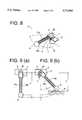
- FIG. 8is a perspective view of a contact-type distance measuring sensor as a second embodiment according to the present invention.
- FIG. 9(a) and 9(b)respectively illustrate the features of the contact-type distance measuring sensor as shown in FIG. 8.
- FIG. 10is a perspective view of a contact-type distance measuring sensor as a third embodiment according to the present invention.
- FIG. 11is a drawing in which the contact-type distance measuring sensor as shown in FIG. 10 is seen from the perspective of A.
- FIG. 12is a perspective view of a contact-type distance measuring sensor as a fourth embodiment according to the present invention.
- FIG. 13is a drawing in which the contact-type distance measuring sensor as shown in FIG. 12 is seen from the perspective of A.
- FIG. 14is a side elevation of a contact-type distance measuring sensor as a fifth embodiment according to the present invention.
- FIG. 15is a drawing to explain the effect of the contact-type distance measuring sensor shown in FIG. 14.
- FIG. 1is a plan view of an automatic moving robot having contact-type distance measuring sensors according to a first embodiment of the present invention.
- the automatic moving robotcomprises robot main unit 15 which has a drive mechanism and a steering mechanism to drive the robot and a working unit 16 that performs tasks such as cleaning.
- contact-type distance measuring sensors 17a through 17dTo robot main unit 15 are attached contact-type distance measuring sensors 17a through 17d, two of said contact-type distance measuring sensors being attached on each side of said robot main unit 15 along a direction X as shown by an arrow X in which the robot moves.
- the automatic moving robotis automatically moving in the direction X along the wall 18.
- contact-type distance measuring sensors 17c and 17dare in contact with the wall 18, thereby their shafts are moved in a counterclockwise direction from their neutral positions.
- the angles of movement of the shaftsare detected by potentiometers not shown in the drawings, through which the distance between the robot main unit 15 and the wall 18 is detected.
- the robotmoves along the wall 18 based on the distance thus detected, and is controlled so that the working unit 16 is in contact with the wall 18.
- the automatic moving robot shown in FIG. 1is controlled so as to perform the operations described below in order to carry out tasks such as cleaning the floor to the edge of the wall.
- the robotis controlled such that the end of the working unit 16 is aligned along a line 24 extending from the two distance measuring sensors 17c and 17d at all times. Consequently, regardless of whether the robot moves away from the wall (FIG. 2) or approaches the wall (FIG. 3), the floor can be cleaned to the edge of the wall 18 at all times.
- FIG. 4is a perspective view of a specific embodiment of contact-type distance measuring sensors 17a through 17d shown in FIG. 1, and FIG. 5 is a side elevation of the same construction.
- the contact-type distance measuring sensor 17comprises a contacting member 8 that comes into contact with an object such as a wall, a shaft 10 that is connected to the contacting member 8 at one end, a potentiometer 1 that detects the angle of movement of shaft 10, a shaft holder 5 that connects the rotational shaft of the potentiometer 1 and the shaft 10, a sensor base 2 that is connected to potentiometer 1 and is used to attach the contact-type distance measuring sensor 17 to a robot, a base claw 3 that is formed integrally with the sensor base 2, a shaft center position determining claw 6 that is formed integrally with the shaft holder 5, and helical coil spring 7 that gives force to the shaft in the direction of its neutral position by sandwiching the base claw 3 and shaft center position determining claw 6 by means of two arms extending from either side of the spring.
- Shaft 10can freely move in a clockwise direction and a counterclockwise direction at a predetermined angle around a rotational shaft 22 of the potentiometer 1. By means of this construction, shaft 10 can freely move within a predetermined plane 20 indicated by dotted lines in FIG. 4.
- Shaft 10moves within the predetermined plane 20 by means of an object coming into contact with the shaft 10 or contacting member 8.
- shaft 10returns to the neutral position by means of the force given by helical coil spring 7.
- FIG. 7(a)is a plan view to explain the operation of the contact-type distance measuring sensor as shown in FIG. 4.
- FIG. 7(a)shows shaft 10 in the neutral condition.
- FIG. 7(b)shows that shaft 10 is moved within the predetermined plane 20 because the contacting member 8 comes into contact with an object 9.
- the distance between the contact-type distance measuring sensor and the objectis calculated using this equation.
- the contacting member 8is actually located at a position beyond angle A due to the elasticity of spring 10 even if the angle detected by potentiometer 1 is A.
- the location of the contacting member 8is determined to be the position indicated by one-dot line.
- the contacting member 8is actually located at the position indicated by a solid line.
- the deviation in the detected position of the contacting member 8does not affect adversely the detection by the contact-type distance measuring sensor because the deviation is not great.
- the shaftcomprises a spring 10 which is an elastic member.
- the shafthas enough elasticity to be bent when a vertical force is applied to the shaft 10 for preventing the shaft 10 from being damaged.
- the flexibility of the shaft 10is preferably larger in a vertical direction than in the horizontal rotational direction so that the shaft 10 is not substantially bent when a horizontal force is applied to the shaft 10.
- the rigidity of the shaft 10is sufficient to prevent the shaft 10 from being substantially bent when a horizontal force is applied to the shaft 10.
- the rigidity of the shaft 10is sufficient to prevent the shaft 10 from being substantially bent when a horizontal rotational torque is applied to the shaft 22 by the helical coil spring 7.
- the shaft 10If the shaft 10 is too flexible, the shaft would droop downward and would be easily deformed in a horizontal direction. Conversely, if the shaft is not flexible enough, the shaft 10 would be too hard to deform when a vertical force was applied to the shaft.
- FIG. 8is a perspective view of a second embodiment of a contact-type distance measuring sensor according to the present invention.
- the construction of the contact-type distance measuring sensor of the second embodimentis identical to that of the contact-type distance measuring sensor of the first embodiment except for the shaft.
- the shaftcomprises two springs 10a and 10b that are aligned parallel to a predetermined plane 20 within which the shaft moves.
- springs 10a and 10bhave elasticity enough to absorb the force Z in a direction vertical to the plane 20 within which the shaft moves.
- FIG. 9(a) and (9b)are respectively plan views of the contact-type distance measuring sensor as the second embodiment according to the present invention.
- the deviation in the detected position of the contacting member 8can be reduced more effectively with this construction, and therefore more accurate distance measurement can be performed in this embodiment.
- damage of the sensor itselfcan be prevented in approximately the same manner as when one spring is used as the shaft.
- FIG. 10is a perspective view of a contact-type distance measuring sensor as a third embodiment according to the present invention.
- FIG. 11is a plan view in which FIG. 10 is seen from the viewpoint of A.
- the basic construction of the contact-type distance measuring sensor of this embodimentis the same as that of the contact-type distance measuring sensor shown in FIGS. 4 and 8.
- the construction of the contact-type distance measuring sensor of the third embodimentis identical to that of the contact-type distance measuring sensor of the first embodiment except for the shaft.
- plate spring 11is used for the shaft.
- the plate springis attached to the shaft holder such that it is easily bent in the direction vertical to the plane 20 within which the shaft moves. More specifically, as shown in FIG. 11, plate spring 11 is attached such that its main surface may be parallel to the plane 20 within which the shaft moves.
- the plate springis not easily deformed in the direction of the movement of the shaft while it is easily deformed in the direction vertical to the plane 20 within which the shaft moves. Therefore, when the force Z vertical to the direction of the movement of the shaft is applied to the shaft or the contacting member, the plate spring is bent due to its elasticity in the same way as the contact-type distance measuring sensor of the second embodiment of the present invention described above, as a result of which unnecessary force is absorbed.
- FIG. 12is a perspective view of a contact-type distance measuring sensor of fourth embodiment of the present invention.
- FIG. 13is a drawing in which FIG. 12 is seen from the perspective of A.
- the construction of the contact-type distance measuring sensor of the fourth embodimentis identical to that of the contact-type distance measuring sensor of the first embodiment except for the shaft.
- the shaftcomprises a coil spring 12 whose spiral configuration is oval.
- Oval coil springshave the characteristic that they are not easily bent in the directions along their longer diameter while they are easily bent in the directions along their shorter diameter. Therefore, by placing the coil spring such that the longer diameter is parallel to the direction of the movement of the shaft, as shown in FIG. 13, a sensor in which deviation in the detected position of the contacting member 8 and damage are reduced can be provided as in the case of the contact-type distance measuring sensors as the second and third embodiments.
- FIG. 14is a side elevation showing a specific construction of a contact-type distance measuring sensor of a fifth embodiment of the present invention.
- the construction of the contact-type distance measuring sensor of the fifth embodimentis identical to that of the contact-type distance measuring sensor of the first embodiment except for the shaft.
- a joint memberis used between shaft 4 and shaft holder 5.
- This joint membercomprises fulcrum 13 and position determining coil spring 14.
- shaft 4 and shaft holder 5can move relative to each other around fulcrum 13.
- Position determining coil spring 14normally gives force to shaft 4 and shaft holder 5 such that shaft holder 5 and shaft 4 are aligned in a straight line (the neutral condition).
- downward force Zis assumed as the force applied to contacting member 8, however when a force in the reverse direction is applied to contacting member 8, shaft 4 moves clockwise around fulcrum 13 and the sensor is prevented from being damaged.
- the contact-type distance measuring sensoris easily bent in the direction vertical to the plane within which the shaft moves, but is not easily bent in the direction of the movement of the shaft, thereby the shear in the detected position of the contacting member can be sufficiently reduced and the sensor is prevented from being damaged.
- the present inventionhas been explained referring to contact-type distance measuring sensors in the first through fifth embodiments described above, as long as the sensor is contact-type, such as an obstacle detecting sensor that comes into contact with an object, the present invention can be applied in connection with such a sensor.
Landscapes
- Physics & Mathematics (AREA)
- General Physics & Mathematics (AREA)
- A Measuring Device Byusing Mechanical Method (AREA)
- Control Of Position, Course, Altitude, Or Attitude Of Moving Bodies (AREA)
- Manipulator (AREA)
Abstract
Description
d=r+L×cosA (1)
Claims (24)
Applications Claiming Priority (2)
| Application Number | Priority Date | Filing Date | Title |
|---|---|---|---|
| JP23954595AJP3267116B2 (en) | 1995-09-19 | 1995-09-19 | Contact sensors and moving objects |
| JP7-239545 | 1995-09-19 |
Publications (1)
| Publication Number | Publication Date |
|---|---|
| US5712961Atrue US5712961A (en) | 1998-01-27 |
Family
ID=17046411
Family Applications (1)
| Application Number | Title | Priority Date | Filing Date |
|---|---|---|---|
| US08/714,363Expired - LifetimeUS5712961A (en) | 1995-09-19 | 1996-09-16 | Contact-type sensor |
Country Status (2)
| Country | Link |
|---|---|
| US (1) | US5712961A (en) |
| JP (1) | JP3267116B2 (en) |
Cited By (25)
| Publication number | Priority date | Publication date | Assignee | Title |
|---|---|---|---|---|
| US6360176B1 (en)* | 1998-04-14 | 2002-03-19 | Mitutoyo Corporation | Touch signal probe |
| WO2002039868A1 (en)* | 2000-11-17 | 2002-05-23 | Duplex Cleaning Machines Pty. Limited | Sensors for robotic devices |
| US6529806B1 (en)* | 1998-05-13 | 2003-03-04 | Gmd Forschungszentrum Informationstechnik Gmbh | Autonomous navigating system having obstacle recognition |
| US6546643B2 (en)* | 2000-02-15 | 2003-04-15 | Carl-Zeiss-Stiftung | Articulated device for the probe head of a coordinate measuring apparatus |
| US6651351B1 (en)* | 1997-06-12 | 2003-11-25 | Werth Messtechnik Gmbh | Coordinate measuring instrument with feeler element and optic sensor for measuring the position of the feeler |
| US20040128847A1 (en)* | 2002-09-18 | 2004-07-08 | Maurice Fracheboud | Touch probing device |
| US20050071880A1 (en)* | 2003-09-29 | 2005-03-31 | Lipsky Scott E. | Method and system for distributing images to client systems |
| WO2005087071A3 (en)* | 2003-12-10 | 2005-11-24 | Vorwerk Co Interholding | Automatically displaceable floor dust collecting device |
| US20060004697A1 (en)* | 2004-06-09 | 2006-01-05 | Lipsky Scott E | Method and system for restricting the display of images |
| US20080167752A1 (en)* | 2006-11-13 | 2008-07-10 | Jacobsen Stephen C | Tracked robotic crawler having a moveable arm |
| US20080215185A1 (en)* | 2006-11-13 | 2008-09-04 | Jacobsen Stephen C | Unmanned ground robotic vehicle having an alternatively extendible and retractable sensing appendage |
| US20080217993A1 (en)* | 2006-11-13 | 2008-09-11 | Jacobsen Stephen C | Conformable track assembly for a robotic crawler |
| US20090030562A1 (en)* | 2007-07-10 | 2009-01-29 | Jacobsen Stephen C | Modular Robotic Crawler |
| US20100174422A1 (en)* | 2009-01-08 | 2010-07-08 | Jacobsen Stephen C | Point And Go Navigation System And Method |
| US20100258365A1 (en)* | 2006-11-13 | 2010-10-14 | Raytheon Sarcos, Llc | Serpentine Robotic Crawler |
| US20100318242A1 (en)* | 2009-06-11 | 2010-12-16 | Jacobsen Stephen C | Method And System For Deploying A Surveillance Network |
| US8002716B2 (en) | 2007-05-07 | 2011-08-23 | Raytheon Company | Method for manufacturing a complex structure |
| US8317555B2 (en) | 2009-06-11 | 2012-11-27 | Raytheon Company | Amphibious robotic crawler |
| US8393422B1 (en) | 2012-05-25 | 2013-03-12 | Raytheon Company | Serpentine robotic crawler |
| US9031698B2 (en) | 2012-10-31 | 2015-05-12 | Sarcos Lc | Serpentine robotic crawler |
| US9409292B2 (en) | 2013-09-13 | 2016-08-09 | Sarcos Lc | Serpentine robotic crawler for performing dexterous operations |
| US9566711B2 (en) | 2014-03-04 | 2017-02-14 | Sarcos Lc | Coordinated robotic control |
| US10071303B2 (en) | 2015-08-26 | 2018-09-11 | Malibu Innovations, LLC | Mobilized cooler device with fork hanger assembly |
| US10807659B2 (en) | 2016-05-27 | 2020-10-20 | Joseph L. Pikulski | Motorized platforms |
| US12311550B2 (en) | 2020-12-31 | 2025-05-27 | Sarcos Corp. | Smart control system for a robotic device |
Families Citing this family (1)
| Publication number | Priority date | Publication date | Assignee | Title |
|---|---|---|---|---|
| CN109855591B (en)* | 2019-03-31 | 2025-07-15 | 上海新朋联众汽车零部件有限公司 | Device for detecting the center point alignment of arc welding robot conductive nozzle and welding gun nozzle |
Citations (25)
| Publication number | Priority date | Publication date | Assignee | Title |
|---|---|---|---|---|
| US4279080A (en)* | 1979-08-28 | 1981-07-21 | Mitutoyo Mfg. Co. Ltd. | Touch signalling probe |
| US4301338A (en)* | 1975-10-04 | 1981-11-17 | Rolls-Royce Limited | Contact-sensing probe |
| US4330942A (en)* | 1981-03-17 | 1982-05-25 | Klingelnberg Sohne | Length-measuring probe for measurement |
| US4477976A (en)* | 1982-12-29 | 1984-10-23 | Kuroda Precision Industries Ltd. | Contact sensor |
| US4488019A (en)* | 1982-03-16 | 1984-12-11 | Mitutoyo Mfg. Co., Ltd. | Touch signal probe |
| US4523382A (en)* | 1982-04-29 | 1985-06-18 | Carl-Zeiss-Stiftung | Work-contact probe head for coordinate-measuring instruments |
| US4547971A (en)* | 1983-04-22 | 1985-10-22 | Futaba Denshi Kogyo K.K. | Touch sensor |
| US4603482A (en)* | 1985-12-30 | 1986-08-05 | Valeron Corporation | Probe shield |
| US4621436A (en)* | 1984-06-21 | 1986-11-11 | Sokkisha Co., Ltd. | Position detecting apparatus |
| US4625417A (en)* | 1985-06-17 | 1986-12-02 | Gte Valeron Corporation | Probe with stylus pressure adjustment |
| US4912988A (en)* | 1987-04-16 | 1990-04-03 | Metrol Co., Ltd. | Touch sensor |
| US4941266A (en)* | 1988-03-11 | 1990-07-17 | Saphirwerk Industrieprodukte Ag | Feeler device for forming a measurement value when sensing a workpiece |
| US4972597A (en)* | 1988-12-15 | 1990-11-27 | Governor of Toyama Prefecture, Yutaka Nakaoki | Three-dimensional displacement gage |
| US5018280A (en)* | 1988-07-20 | 1991-05-28 | Carl-Zeiss-Stiftung, Heidenheim/Brenz | Method and device for the operation of a workpiece-contacting probe head of the switching type |
| US5029399A (en)* | 1988-07-08 | 1991-07-09 | Renishaw Plc | Probe for use with measuring apparatus |
| US5111592A (en)* | 1991-07-12 | 1992-05-12 | Carl-Zeiss-Stiftung, Heidenheim/Brenz | Probe head of the switching type |
| US5208993A (en)* | 1991-03-28 | 1993-05-11 | Renishaw Metrology Limited | Touch probe |
| US5224689A (en)* | 1991-12-16 | 1993-07-06 | Jordan Valchev Georgiev | Shock absorbing device allowing reducing the vehicle weight |
| JPH05204448A (en)* | 1992-01-23 | 1993-08-13 | Toyota Motor Corp | Unmanned carrier |
| US5299360A (en)* | 1990-03-06 | 1994-04-05 | Marposs Societa' Per Azioni | Probe for checking linear dimensions |
| US5309592A (en)* | 1992-06-23 | 1994-05-10 | Sanyo Electric Co., Ltd. | Cleaning robot |
| US5333388A (en)* | 1990-01-16 | 1994-08-02 | British Technology Group Limited | Probes |
| US5355589A (en)* | 1992-05-28 | 1994-10-18 | Wolfgang Madlener | Sensing head for the three-dimensional sensing of workpiece |
| US5509211A (en)* | 1993-07-31 | 1996-04-23 | Johannes Heidenhain Gmbh | Multi-coordinate probe |
| US5535861A (en)* | 1995-06-08 | 1996-07-16 | Lord Corporation | Dual-rate linear damper |
- 1995
- 1995-09-19JPJP23954595Apatent/JP3267116B2/ennot_activeExpired - Fee Related
- 1996
- 1996-09-16USUS08/714,363patent/US5712961A/ennot_activeExpired - Lifetime
Patent Citations (25)
| Publication number | Priority date | Publication date | Assignee | Title |
|---|---|---|---|---|
| US4301338A (en)* | 1975-10-04 | 1981-11-17 | Rolls-Royce Limited | Contact-sensing probe |
| US4279080A (en)* | 1979-08-28 | 1981-07-21 | Mitutoyo Mfg. Co. Ltd. | Touch signalling probe |
| US4330942A (en)* | 1981-03-17 | 1982-05-25 | Klingelnberg Sohne | Length-measuring probe for measurement |
| US4488019A (en)* | 1982-03-16 | 1984-12-11 | Mitutoyo Mfg. Co., Ltd. | Touch signal probe |
| US4523382A (en)* | 1982-04-29 | 1985-06-18 | Carl-Zeiss-Stiftung | Work-contact probe head for coordinate-measuring instruments |
| US4477976A (en)* | 1982-12-29 | 1984-10-23 | Kuroda Precision Industries Ltd. | Contact sensor |
| US4547971A (en)* | 1983-04-22 | 1985-10-22 | Futaba Denshi Kogyo K.K. | Touch sensor |
| US4621436A (en)* | 1984-06-21 | 1986-11-11 | Sokkisha Co., Ltd. | Position detecting apparatus |
| US4625417A (en)* | 1985-06-17 | 1986-12-02 | Gte Valeron Corporation | Probe with stylus pressure adjustment |
| US4603482A (en)* | 1985-12-30 | 1986-08-05 | Valeron Corporation | Probe shield |
| US4912988A (en)* | 1987-04-16 | 1990-04-03 | Metrol Co., Ltd. | Touch sensor |
| US4941266A (en)* | 1988-03-11 | 1990-07-17 | Saphirwerk Industrieprodukte Ag | Feeler device for forming a measurement value when sensing a workpiece |
| US5029399A (en)* | 1988-07-08 | 1991-07-09 | Renishaw Plc | Probe for use with measuring apparatus |
| US5018280A (en)* | 1988-07-20 | 1991-05-28 | Carl-Zeiss-Stiftung, Heidenheim/Brenz | Method and device for the operation of a workpiece-contacting probe head of the switching type |
| US4972597A (en)* | 1988-12-15 | 1990-11-27 | Governor of Toyama Prefecture, Yutaka Nakaoki | Three-dimensional displacement gage |
| US5333388A (en)* | 1990-01-16 | 1994-08-02 | British Technology Group Limited | Probes |
| US5299360A (en)* | 1990-03-06 | 1994-04-05 | Marposs Societa' Per Azioni | Probe for checking linear dimensions |
| US5208993A (en)* | 1991-03-28 | 1993-05-11 | Renishaw Metrology Limited | Touch probe |
| US5111592A (en)* | 1991-07-12 | 1992-05-12 | Carl-Zeiss-Stiftung, Heidenheim/Brenz | Probe head of the switching type |
| US5224689A (en)* | 1991-12-16 | 1993-07-06 | Jordan Valchev Georgiev | Shock absorbing device allowing reducing the vehicle weight |
| JPH05204448A (en)* | 1992-01-23 | 1993-08-13 | Toyota Motor Corp | Unmanned carrier |
| US5355589A (en)* | 1992-05-28 | 1994-10-18 | Wolfgang Madlener | Sensing head for the three-dimensional sensing of workpiece |
| US5309592A (en)* | 1992-06-23 | 1994-05-10 | Sanyo Electric Co., Ltd. | Cleaning robot |
| US5509211A (en)* | 1993-07-31 | 1996-04-23 | Johannes Heidenhain Gmbh | Multi-coordinate probe |
| US5535861A (en)* | 1995-06-08 | 1996-07-16 | Lord Corporation | Dual-rate linear damper |
Cited By (47)
| Publication number | Priority date | Publication date | Assignee | Title |
|---|---|---|---|---|
| US6651351B1 (en)* | 1997-06-12 | 2003-11-25 | Werth Messtechnik Gmbh | Coordinate measuring instrument with feeler element and optic sensor for measuring the position of the feeler |
| US6360176B1 (en)* | 1998-04-14 | 2002-03-19 | Mitutoyo Corporation | Touch signal probe |
| US6529806B1 (en)* | 1998-05-13 | 2003-03-04 | Gmd Forschungszentrum Informationstechnik Gmbh | Autonomous navigating system having obstacle recognition |
| US6546643B2 (en)* | 2000-02-15 | 2003-04-15 | Carl-Zeiss-Stiftung | Articulated device for the probe head of a coordinate measuring apparatus |
| WO2002039868A1 (en)* | 2000-11-17 | 2002-05-23 | Duplex Cleaning Machines Pty. Limited | Sensors for robotic devices |
| US20040117064A1 (en)* | 2000-11-17 | 2004-06-17 | Mcdonald Murray | Sensors for robotic devices |
| US6999850B2 (en) | 2000-11-17 | 2006-02-14 | Mcdonald Murray | Sensors for robotic devices |
| US6886265B2 (en)* | 2002-09-18 | 2005-05-03 | Mercartex Sa | Touch probing device |
| US20040128847A1 (en)* | 2002-09-18 | 2004-07-08 | Maurice Fracheboud | Touch probing device |
| US8577955B2 (en) | 2003-09-29 | 2013-11-05 | Eqapez Foundation, L.L.C. | Method and system for distributing images to client systems |
| US20050071867A1 (en)* | 2003-09-29 | 2005-03-31 | Lipsky Scott E. | Method and system for distributing images to client systems |
| US20050071880A1 (en)* | 2003-09-29 | 2005-03-31 | Lipsky Scott E. | Method and system for distributing images to client systems |
| US9214037B2 (en)* | 2003-09-29 | 2015-12-15 | Ol Security Limited Liability Company | Method and system for distributing images to client systems |
| US8949380B2 (en) | 2003-09-29 | 2015-02-03 | Eqapez Foundation, L.L.C. | Method and system for distributing images to client systems |
| US20100312819A1 (en)* | 2003-09-29 | 2010-12-09 | Lipsky Scott E | Method and system for distributing images to client systems |
| WO2005087071A3 (en)* | 2003-12-10 | 2005-11-24 | Vorwerk Co Interholding | Automatically displaceable floor dust collecting device |
| CN101305895B (en)* | 2003-12-10 | 2010-10-20 | 沃维克股份有限公司 | Automatically displaceable floor dust collecting device |
| DE10357636B4 (en)* | 2003-12-10 | 2013-05-08 | Vorwerk & Co. Interholding Gmbh | Automatically movable floor dust collecting device |
| CN101310665B (en)* | 2003-12-10 | 2011-12-21 | 沃维克股份有限公司 | Automatically displaceable floor dust collecting device |
| CN101310664B (en)* | 2003-12-10 | 2010-10-13 | 沃维克股份有限公司 | Automatically displaceable floor dust collecting device |
| US20060004697A1 (en)* | 2004-06-09 | 2006-01-05 | Lipsky Scott E | Method and system for restricting the display of images |
| US20080215185A1 (en)* | 2006-11-13 | 2008-09-04 | Jacobsen Stephen C | Unmanned ground robotic vehicle having an alternatively extendible and retractable sensing appendage |
| US20100201185A1 (en)* | 2006-11-13 | 2010-08-12 | Raytheon Sarcos, Llc | Conformable Track Assembly For A Robotic Crawler |
| US20080167752A1 (en)* | 2006-11-13 | 2008-07-10 | Jacobsen Stephen C | Tracked robotic crawler having a moveable arm |
| US8002365B2 (en) | 2006-11-13 | 2011-08-23 | Raytheon Company | Conformable track assembly for a robotic crawler |
| US8042630B2 (en) | 2006-11-13 | 2011-10-25 | Raytheon Company | Serpentine robotic crawler |
| US20100258365A1 (en)* | 2006-11-13 | 2010-10-14 | Raytheon Sarcos, Llc | Serpentine Robotic Crawler |
| US8185241B2 (en) | 2006-11-13 | 2012-05-22 | Raytheon Company | Tracked robotic crawler having a moveable arm |
| US8205695B2 (en) | 2006-11-13 | 2012-06-26 | Raytheon Company | Conformable track assembly for a robotic crawler |
| US20080217993A1 (en)* | 2006-11-13 | 2008-09-11 | Jacobsen Stephen C | Conformable track assembly for a robotic crawler |
| US8002716B2 (en) | 2007-05-07 | 2011-08-23 | Raytheon Company | Method for manufacturing a complex structure |
| US8434208B2 (en) | 2007-05-07 | 2013-05-07 | Raytheon Company | Two-dimensional layout for use in a complex structure |
| US20090030562A1 (en)* | 2007-07-10 | 2009-01-29 | Jacobsen Stephen C | Modular Robotic Crawler |
| US8571711B2 (en) | 2007-07-10 | 2013-10-29 | Raytheon Company | Modular robotic crawler |
| US20100174422A1 (en)* | 2009-01-08 | 2010-07-08 | Jacobsen Stephen C | Point And Go Navigation System And Method |
| US8392036B2 (en) | 2009-01-08 | 2013-03-05 | Raytheon Company | Point and go navigation system and method |
| US8935014B2 (en) | 2009-06-11 | 2015-01-13 | Sarcos, Lc | Method and system for deploying a surveillance network |
| US8317555B2 (en) | 2009-06-11 | 2012-11-27 | Raytheon Company | Amphibious robotic crawler |
| US20100318242A1 (en)* | 2009-06-11 | 2010-12-16 | Jacobsen Stephen C | Method And System For Deploying A Surveillance Network |
| US8393422B1 (en) | 2012-05-25 | 2013-03-12 | Raytheon Company | Serpentine robotic crawler |
| US9031698B2 (en) | 2012-10-31 | 2015-05-12 | Sarcos Lc | Serpentine robotic crawler |
| US9409292B2 (en) | 2013-09-13 | 2016-08-09 | Sarcos Lc | Serpentine robotic crawler for performing dexterous operations |
| US9566711B2 (en) | 2014-03-04 | 2017-02-14 | Sarcos Lc | Coordinated robotic control |
| US10071303B2 (en) | 2015-08-26 | 2018-09-11 | Malibu Innovations, LLC | Mobilized cooler device with fork hanger assembly |
| US10814211B2 (en) | 2015-08-26 | 2020-10-27 | Joseph Pikulski | Mobilized platforms |
| US10807659B2 (en) | 2016-05-27 | 2020-10-20 | Joseph L. Pikulski | Motorized platforms |
| US12311550B2 (en) | 2020-12-31 | 2025-05-27 | Sarcos Corp. | Smart control system for a robotic device |
Also Published As
| Publication number | Publication date |
|---|---|
| JP3267116B2 (en) | 2002-03-18 |
| JPH0989503A (en) | 1997-04-04 |
Similar Documents
| Publication | Publication Date | Title |
|---|---|---|
| US5712961A (en) | Contact-type sensor | |
| US5309592A (en) | Cleaning robot | |
| EP0541811B1 (en) | Working device | |
| US4523383A (en) | Position sensing apparatus | |
| JP3282206B2 (en) | Obstacle detection device for mobile work robot | |
| JP3201208B2 (en) | Autonomous vehicles | |
| CN100411574C (en) | Ground dust collecting device capable of automatically moving | |
| EP1852761A2 (en) | Robot having an obstacle detection unit and method of controlling the same | |
| EP0299033B1 (en) | Feeler device, particularly for copying machines | |
| JP7311343B2 (en) | robot | |
| KR20200007004A (en) | Hand instruments, gripping systems and gripping programs | |
| JP7109161B2 (en) | Mechanism Model Parameter Estimation Method for Articulated Robots | |
| CN114341751B (en) | Apparatus and method for calibrating laser displacement sensor for robot | |
| US11872700B2 (en) | Robot with a torque sensor and a force sensor | |
| US20230266186A1 (en) | Torque sensor element and torque sensor | |
| CN108147325B (en) | Fork truck and corner measurement structure thereof | |
| US5383368A (en) | Deflection sensor for robot links | |
| US5243872A (en) | Robotic hand for controlling movement in multiple axes | |
| CN210277061U (en) | Collision detection device and dust collection robot | |
| US4687979A (en) | Control system for a robotic gripper | |
| CN109645900B (en) | Collision detection device and dust collection robot | |
| JP3219566B2 (en) | Cleaning robot | |
| JP7436241B2 (en) | robot system | |
| JPH06297379A (en) | Overtravel detecting device for industrial robot | |
| JP2617489B2 (en) | Joint sensor |
Legal Events
| Date | Code | Title | Description |
|---|---|---|---|
| AS | Assignment | Owner name:MINOLTA CO., LTD., JAPAN Free format text:ASSIGNMENT OF ASSIGNORS INTEREST;ASSIGNOR:MATSUO, TAKASHI;REEL/FRAME:008316/0170 Effective date:19960910 | |
| FEPP | Fee payment procedure | Free format text:PAYOR NUMBER ASSIGNED (ORIGINAL EVENT CODE: ASPN); ENTITY STATUS OF PATENT OWNER: LARGE ENTITY | |
| STCF | Information on status: patent grant | Free format text:PATENTED CASE | |
| FPAY | Fee payment | Year of fee payment:4 | |
| FPAY | Fee payment | Year of fee payment:8 | |
| FPAY | Fee payment | Year of fee payment:12 | |
| AS | Assignment | Owner name:KONICA MINOLTA, INC., JAPAN Free format text:CHANGE OF NAME;ASSIGNOR:KONICA MINOLTA HOLDINGS, INC.;REEL/FRAME:031815/0828 Effective date:20130401 Owner name:KONICA MINOLTA HOLDINGS, INC., JAPAN Free format text:MERGER;ASSIGNOR:MINOLTA CO., LTD.;REEL/FRAME:031815/0890 Effective date:20031010 | |
| AS | Assignment | Owner name:MONEUAL, INC., KOREA, REPUBLIC OF Free format text:ASSIGNMENT OF ASSIGNORS INTEREST;ASSIGNOR:KONICA MINOLTA, INC.;REEL/FRAME:033580/0231 Effective date:20140820 |