US5712942A - Optical communications system having distributed intelligence - Google Patents
Optical communications system having distributed intelligenceDownload PDFInfo
- Publication number
- US5712942A US5712942AUS08/645,108US64510896AUS5712942AUS 5712942 AUS5712942 AUS 5712942AUS 64510896 AUS64510896 AUS 64510896AUS 5712942 AUS5712942 AUS 5712942A
- Authority
- US
- United States
- Prior art keywords
- optical
- interconnection
- modules
- recited
- controller
- Prior art date
- Legal status (The legal status is an assumption and is not a legal conclusion. Google has not performed a legal analysis and makes no representation as to the accuracy of the status listed.)
- Expired - Lifetime
Links
Images

Classifications
- H—ELECTRICITY
- H04—ELECTRIC COMMUNICATION TECHNIQUE
- H04B—TRANSMISSION
- H04B10/00—Transmission systems employing electromagnetic waves other than radio-waves, e.g. infrared, visible or ultraviolet light, or employing corpuscular radiation, e.g. quantum communication
- H04B10/07—Arrangements for monitoring or testing transmission systems; Arrangements for fault measurement of transmission systems
- H04B10/075—Arrangements for monitoring or testing transmission systems; Arrangements for fault measurement of transmission systems using an in-service signal
- H04B10/079—Arrangements for monitoring or testing transmission systems; Arrangements for fault measurement of transmission systems using an in-service signal using measurements of the data signal
Definitions
- the inventionrelates to optical fiber communications systems. More particularly, the invention relates to the monitoring and maintenance of inter-connected optical fibers within a communications system.
- optical fiber distribution flees or lightguide cross-connect (LGX) framesare used for optical coupling within the communications system, e.g., for coupling optical fibers from an outside environment entering a customer's premises to internal fibers for equipment on the customer's premises.
- a typical distribution framehouses a multiplicity of shelves, each shelf including one or more optical coupling or interconnection modules in which the ends of incoming fibers and/or outgoing internal optical fibers are adapted for interconnection therebetween by appropriate connectors.
- the incoming and outgoing optical fibersare connected to respective coupling modules, and a corresponding plurality of optical cross-connect jumper cables (i.e., patch cords) optically connect the incoming optical fibers from one coupling module to the desired outgoing optical fibers from the appropriate coupling module.
- a corresponding plurality of optical cross-connect jumper cablesi.e., patch cords
- the incoming and outgoing fibersare terminated at different locations within the same distribution frame and cross-connect jumpers optically connect the appropriate fibers from one location to another.
- testing the integrity and quality of the lines and/or connections therebetweenoften is performed manually, making it a difficult, cumbersome, costly and labor-intensive undertaking. It is known to launch test signals to determine the condition of fibers (e.g., see U.S. Pat. No. 5,329,392 issued to Cohen). However, this determination is performed manually, and typically in reaction to a system malfunction rather than an alert from a continuous monitoring system. Also, it is known to determine the condition of patch connections between coupling modules (e.g., see U.S. Pat. No. 5,461,693 issued to Pimpinella).
- optical interconnections within a distribution frameare optically routed in series through an external testing or monitoring structure, e.g., one or more additional frames housing shelves of testing and/or monitoring equipment controlled by a single host or controller.
- an external testing or monitoring structuree.g., one or more additional frames housing shelves of testing and/or monitoring equipment controlled by a single host or controller.
- each optical interconnectionhas a first additional optical fiber channel routed to the testing location and a second additional optical fiber channel routed from the testing location.
- Monitoringtypically is performed by sequentially polling the interconnections of each individual fiber, which is especially inefficient and impractical for communications systems having a distribution frame with more than a minimal number of optical interconnections.
- each fibertakes longer than at least 60 seconds to test. Therefore, any fiber disruption will not be detected thereby for at least 60 seconds times the number of fibers between the disrupted fiber and the fiber currently being polled. Such results are non-optimum in current optical communications systems.
- a more efficient, autonomous, automatic and continuous system of monitoring distribution frames and the optical fibers connected thereto within optical communications systemsis sought.
- the inventionis embodied in a distributed intelligence optical fiber communications system having automated and continuous monitoring and testing of the optical fibers and their distribution frame connections.
- a distributed intelligence optical fiber communications systemhaving automated and continuous monitoring and testing of the optical fibers and their distribution frame connections.
- the distribution frameincludes interconnection modules having actively intelligent microcontrollers thereon.
- the distribution framealso includes inventive electrical and optical interconnect fabrics between the distributed intelligence of the interconnection modules and a system controller.
- the distributed intelligence interconnection modulesallow monitoring, testing and/or related activities of the overall optical communications system to be performed locally at the interconnection modules.
- the inventive modulessubstantially reduce optical fiber routing and enable more effective monitoring and testing operations to be performed, while maintaining compatibility with existing conventional cross-connect, switching and network architectures.
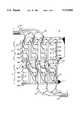
- FIG. 1is a schematic diagram of a conventional distribution frame used in an optical communications system
- FIG. 2is a side, schematic diagram of an illustrative portion of a distribution frame used in an optical communications system according to an embodiment of the invention
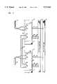
- FIG. 3is a schematic diagram of a conventional distribution frame used in an optical communications system showing the electrical and optical interconnection fabrics according to an embodiment of the invention.
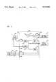
- FIG. 4is a schematic diagram of an interconnection module according to an embodiment of the invention.
- Distribution frame 10includes at least one shelf (e.g., shelves 12 and 14) with one or more interconnection modules installed within available slots on each shelf.
- interconnection modules 16a, 16b, 16c and 16dare mounted or otherwise operably installed within shelf 12 and interconnection modules 18a, 18b, 18c and 18d are mounted within shelf 14.
- distribution frame 10also is suitable for use with existing modules that, e.g., occupy two (2) or more shelf slots yet have three (3) or more optical channels.
- the interconnection modulesare used to optically cross-connect optical channels, e.g., from a first optical cable 22 to a second optical cable 24.
- a plurality of first optical channels 32, 34 and 36each having a transmit fiber and a receive fiber, are optically connected to interconnection modules 16a, 16b and 16c, respectively.
- a plurality of second optical channels 42, 44 and 46are optically connected to interconnection modules 18b, 18c and 18d, respectively.
- Corresponding pairs of jumper fibers or optical cross-connects(shown as 52, 54 and 56) interconnect first optical channels with the desired second optical channels.
- interconnection modules being cross-connectedare shown installed within adjacent shelves 12, 14, it is known and will be more evident from subsequent discussions herein that the interconnection modules being cross-connected are capable of being located in different physical areas (e.g., different bays) of the same distribution frame, or even different distribution frames within the same optical communications system.
- the physical distance between cross-connected interconnection modulesare limited, e.g., by the practical length of cross-connect jumpers used therebetween.
- first optical cable 22represents, e.g., a plurality of incoming optical channels entering the facility (often referred to as “OSP” or “outside plant” cable).
- second optical channel 24represents a plurality of optical channels for equipment or other uses within the facility (often referred to as "equipment" cable).
- interconnection module 16a in shelf 12is shown in optical connection with interconnection module 18b in shelf 14 via jumper fiber pair 52.
- Each interconnection modulehas a first jack pair 62 (e.g., a receive or Rx jack 62a and a transmit or Tx jack 62b) typically used for connection with an optical channel and a second pair of jacks 64a and 64b, typically for connection with a cross-connect jumper pair, as shown.
- a single interconnection moduledirectly couples a first optical channel to a second optical channel. That is, a first optical channel is operably connected to the first jack pair 62 of a desired interconnection module and a second optical channel is operably connected to the second jack pair 64 of the same interconnection module.
- interconnection module jacksare adapted for optically coupling various types of optical fibers.
- each interconnection moduleis configured, e.g., so that the Tx jack of one pair is optically coupled to the Rx jack of the other jack pair. In this manner, consistency is maintained throughout distribution frame 10 with respect to the connections that subsequently are made to the interconnection modules.
- first optical channel 32has a transmit fiber shown optically connected to Rx jack 62a and a receive fiber shown optically connected to Tx jack 62b of interconnection module 16a on shelf 12.
- a transmit fiberis shown optically connected to Rx jack 62a (of interconnection module 18b) and a receive fiber is shown optically connected to Tx jack 62b (of interconnection module 18b).
- each Tx jack 64bis connected to the Rx jack 64a of the cross-connected interconnection module.
- Rx jack 64a of interconnection module 16ais optically cross-coupled to Tx jack 64b of interconnection module 18b
- Tx jack 64b of interconnection module 16ais optically cross-coupled to Rx jack 64a of interconnection module 18b.
- an optical signal that is assumed to begin from the transmit fiber of first optical channel 32is transmitted to Rx jack 62a of interconnection module 16a, out of Tx jack 64b of interconnection module 16a, through the appropriate cross-connect fiber of jumper pair 52 to Rx jack 64a of interconnection module 18b, out of Tx jack 64b of interconnection module 18b, and to the receive fiber of second optical channel 42.
- optical informationis transmitted to Rx jack 62a of interconnection module 18b, out of Tx jack 64b of interconnection module 18b, through the appropriate cross-connect fiber of jumper pair 52 to Rx 64a of interconnection module 16a, out of Tx jack 62b of interconnection module 16a, and to the receive fiber of first optical channel 32.
- each pair of optical cross-connect jumpersis replaced by (i) a pair of optical fibers routed from the first of two interconnection modules (e.g., from second jack pair 64a-b) to the necessary testing/monitoring instrumentation and (ii) a pair of optical fibers routed from the instrumentation to the second interconnection module.
- the testing/monitoring instrumentationis installed similarly to existing interconnection modules (e.g., on shelves) near the interconnection module shelves, if sufficient space exists.
- conventional testing/monitoring instrumentationis not located wholly or partially within any of the interconnection modules.
- the inventionmakes use of an interconnection module configuration that allows for controllers, microcontrollers and other "intelligence” or “intelligent devices” to be distributed conveniently throughout the distribution frames rather than having a plurality of passive modules in a given distribution frame routed to and from an individual testing/monitoring location.
- the inventive interconnection module configurationis used with an inventive interconnection fabric arrangement that facilitates this distributed intelligence.
- the terms “intelligent devices” and “distributed intelligence” in this contextare intended to encompass any active mechanical, electronic, optical and electro-optic components, including circuitry, microcontrollers and microprocessors, that contribute to those functions that are at least partially performed within the inventive interconnection module for the purpose of determining "identifiable operating characteristics".
- the term “identifiable operating characteristics”is intended to include the overall operability or an otherwise qualitative condition of the optical fibers, connectors and/or connections used within the optical communications system of interest. Such functions include testing, monitoring, reading, decoding, analyzing and the like.
- inventive interconnection modulese.g., 16a and 18b
- inventive interconnection modules 16a, 18binclude a distributed intelligence arrangement (shown generally as 66) between their first (62) and second (64) jack pairs.
- the arrangementenables operable connection with an electrical interconnection fabric (shown as 72) and an optical interconnection fabric (shown as 74) in addition to the conventional optical cross-connection between optical channel 32 and optical channel 42.
- Interconnection modules including distributed intelligenceare interchangeable with conventional interconnection modules and, except for their distributed intelligence arrangement, have conventional structure.
- Interconnection modules having distributed intelligenceinclude a front face 76 having conventional jacks for optical cross-connection. Also, the inventive interconnection modules each have a rear face 78 for operable connection to interconnection fabrics 72, 74.
- at least one optical jack 82is adapted for optical connection to optical interconnection fabric 74 via an optical fiber coupling 84 and at least one pair of electrical connectors 86 is adapted for electrical connection of at least the distributed intelligence portion 66 of the interconnection modules to electrical interconnection fabric 72 via wires 88.
- both electrical interconnection fabric 72 and optical interconnection fabric 74have a characteristic cascading scheme that, unlike conventional optical communications systems, substantially reduces unnecessary duplication of optical fibers routed between the distribution flames and any remote frame or system controlling equipment, e.g., a controller 90.
- interconnection modules within a shelfare adapted to be electrically coupled to a corresponding backplane arrangement or shelf controller interface (SCI) bus 91, which is electrically coupled to a corresponding shelf controller or shelf controller module (SCM) 92.
- SCIshelf controller interface
- Shelf controllers within a bayare electrically coupled via an interconnection bus 94 (e.g., a local area network or LAN bus) to a corresponding bay controller 95.
- bay controllersare electrically coupled to controller 90 through said interconnection bus 94.
- Shelf controllers 92 and bay controllers 95typically take the form of interconnection modules or backplane arrangements and thus, in actual practice, are installed, e.g., within spare locations in existing shelves.
- Optical connection between interconnection modules and controller 90is similar.
- a plurality of optical switchesfunction as controllers at the shelf, bay and system levels in a similar cascading scheme.
- each shelfhas an optical switch 102 for optically coupling thereto the interconnection modules within that shelf.
- shelf controlling optical switches 102are optically coupled to an optical switch 104 corresponding to the bay within which the shelf is located.
- Each bay controlling optical switch 104is optically coupled to a system optical switch 106 for optical connection to controller 90.
- controller 90is a frame controller providing a gateway between interconnection bus 94 and the next higher network level.
- controller 90is a system controller for distribution frame 10 and is operably connected to a client server (not shown) that, in a conventional arrangement, is operably connected to other system controllers within an optical communications network. That is, system controller 90 is a network gateway outside of the plant in which distribution frame 10 resides.
- Inventive interconnection module 16ahas a plurality of input jacks 62a, 62b, 64a, 64b on front face 76 that are consistent with the input jacks of conventional interconnection modules, thus contributing to the interchangeability of interconnection module 16a with conventional interconnection modules. Such interchangeability is a significant feature of the inventive interconnection module.
- Interconnection module 16ahas a first wavelength division multiplexer (WDM) 124 with an input optically coupled to Rx jack 62a and an output optically coupled to an optical tap 126.
- WDMwavelength division multiplexer
- One output of optical tap 126is optically coupled to Tx jack 64b and the other output is coupled to a microcontroller 128 or other suitable device for interpreting the information collected by optical tap 126.
- microcontroller 128may have a light detecting component such as a photodiode (not shown) that converts the light coupled from optical tap 126 to an electrical signal used internally by microcontroller 128 or by an external passive device such as an LED 134 coupled to microcontroller 128.
- microcontroller 128may have receiving components capable of interpreting the optical information coupled from optical tap 126.
- microcontroller 128is electrically connected to electrical interconnection fabric 72 via an electrical coupling 142.
- Tx jack 62bis optically coupled to the output of a second WDM 144 (the primary direction of optical transmission is depicted in FIG. 4 by arrows).
- the first of two inputs of second WDM 144is optically coupled to optical interconnection fabric 74 and the second input is optically coupled to the output of a third WDM 148.
- the input of third WDM 148is optically coupled to Rx jack 64a.
- WDM 144 and/or WDM 148are suitable for an optical tap (not shown) to be coupled therewith.
- an optical signal transmitted from first optical channel 32is received by interconnection module 16a via Rx jack 62a.
- the optical signalis optically coupled to Tx jack 64b through first WDM 124 and optical tap 126.
- First WDM 124separates portions of the incoming optical signal, e.g., based on frequency, and transmits the desired components to optical tap 126.
- Optical tap 126deflects a small portion of the optical signal to microcontroller 128 for monitoring, testing and/or other analysis.
- the remaining portion of the optical signalis transmitted to Tx jack 64b for subsequent optical coupling to the Rx jack (i.e., Rx jack 64a) of a cross-connected interconnection module (i.e., interconnection module 18b).
- Microcontroller 128is capable of continuously monitoring the content and/or strength of the optical signal it receives from optical tap 126 to determine if an appropriate action needs to be performed. Also, because microcontroller 128 is electrically connected via electrical interconnection fabric 72 to system controller 90, electrical information can be transmitted therebetween as needed.
- microcontroller 128determines that the strength of the optical signal it receives from optical tap 126 is questionable, such information can be sent to system controller 90 for necessary processing.
- system controller 90controls transmission of the appropriate optical test signals through optical interconnection fabric 74 and WDMs 142 and 144 to Rx jack 62a and/or Tx jack 62b of the interconnection module that originally sent the information.
- test signalsinclude, e.g., optical time domain reflectometry (OTDR) test signals in accordance with conventional OTDR principles. In this manner, the integrity of first optical channel 32 and jacks 62a, 62b are tested continuously and automatically.
- OTDRoptical time domain reflectometry
- microcontroller 128is an actively intelligent device, it can be configured to include addressable functions. Thus, microcontroller 128 is suitable for transmitting electrical information containing address information identifying the source of the information (i.e., the interconnection module from which the information was transmitted). Also, although an optical signal strength testing operation is described above, it is within the scope of the invention for microcontroller 128 to analyze the content of tapped optical information and to communicate with system controller 90 accordingly. In this manner, microcontroller 128 is capable of incorporating control information, monitoring statistic information and other content-based information initiated by microcontroller into the electrical information transmitted to system controller 90 or other interconnection modules.
- inventive interconnection modulesallow them to be installed within existing distribution flames and to become part of the overall optical communications system.
- a newly installed interconnection moduleis capable of transmitting its identity, module type and other characteristic information to system controller 90 and to other interconnection modules within the optical communications system via electrical interconnection fabric 72. Therefore, the overall configuration of the optical communications system is capable of being updated automatically upon installation of an inventive interconnection module therein.
- the distributed intelligenceto cause an interconnection module to shifting into a local operating mode or a self-diagnostic mode in the event of a network emergency.
- the results of such actionsinclude, for example, self healing in the form of rerouting the optical connections of the interconnection module in question. Also, continued operation in the event of power failure is possible through local operating modes.
- Microcontroller 128is capable of including therewith other sensing and/or testing equipment, and is capable of incorporating information in addition to that transmitted via Rx jack 62a.
- microcontroller 128can include or be replaced by a sensor that determines the temperature and/or quality of the air surrounding interconnection module 16a. Such information can be used in monitoring and/or testing functions.
- microcontroller 128is capable of being configured to analyze previous monitoring information and to perform statistical performance monitoring based on such information. In this manner, the interconnection modules are actively performing failure prediction functions instead of passively reacting to an established threshold condition.
- microcontroller 128Other functions adaptable for use by microcontroller 128 in this regard include fiber tracing, protection line switching, monitoring the surrounding environment. All of these functions, as well as those discussed herein previously, are capable of performance in both single mode and multi-mode optical fiber.
- the characteristically branched electrical and optical interconnection fabrics 72, 74allow the distribution frames within an optical communications system to be monitored automatically. Also, the distributed intelligence allows most if not all of the monitoring, processing and the like to be performed locally (i.e., at the interconnection modules) through massive or distributed parallel processing, rather than passively transmitting the information from the interconnection modules to a remotely located system controller.
- interconnection module 16ais optically connected to the first optical channel and cross-connected with interconnection module 18b, which is assumed to be optically connected to the second optical channel
- the distributed intelligence installed in each interconnection moduleis used to monitor the operation and maintenance of that optical communication channel.
- SCMs 92electrically polls, in real time, the interconnection modules within its respective shelf for any information such as monitoring status.
- This simultaneous pollingepitomizes the distributed or massive parallel processing effort of the invention.
- the distributed intelligencedoes not require polling type sharing and thus does not affect the responsiveness of the system.
- communication systems using massive parallel processing techniquesare not limited by the number of optical fiber channels operating therein.
- an SCMreceives a positive status report from an interconnection module (i.e., a flagged event has occurred at the interconnection module)
- information concerning the flagged event, the interconnection module originating the flagged event and any control information for responding appropriately to the flagged eventis transmitted from the respective SCM to system controller 90.
- appropriate information or test signalscan be transmitted from system controller 90 to the interconnection module from which the information was received.
- information and/or test signalscan be transmitted to the interconnection module that is cross-connected to the interconnection module from which the flagged event information was sent. In this manner, the entire optical communications system is monitored simultaneously and tested automatically when necessary or requested.
Landscapes
- Physics & Mathematics (AREA)
- Electromagnetism (AREA)
- Engineering & Computer Science (AREA)
- Computer Networks & Wireless Communication (AREA)
- Signal Processing (AREA)
- Optical Communication System (AREA)
- Mechanical Coupling Of Light Guides (AREA)
Abstract
Description
Claims (17)
Priority Applications (4)
| Application Number | Priority Date | Filing Date | Title |
|---|---|---|---|
| US08/645,108US5712942A (en) | 1996-05-13 | 1996-05-13 | Optical communications system having distributed intelligence |
| CA002200384ACA2200384C (en) | 1996-05-13 | 1997-03-19 | An optical communications system having distributed intelligence |
| EP97303083AEP0808040A3 (en) | 1996-05-13 | 1997-05-06 | Optical communications system having distributed intelligence and monitoring of the fibres |
| JP9121368AJPH1056430A (en) | 1996-05-13 | 1997-05-13 | Optical communication system with distributed intelligence |
Applications Claiming Priority (1)
| Application Number | Priority Date | Filing Date | Title |
|---|---|---|---|
| US08/645,108US5712942A (en) | 1996-05-13 | 1996-05-13 | Optical communications system having distributed intelligence |
Publications (1)
| Publication Number | Publication Date |
|---|---|
| US5712942Atrue US5712942A (en) | 1998-01-27 |
Family
ID=24587670
Family Applications (1)
| Application Number | Title | Priority Date | Filing Date |
|---|---|---|---|
| US08/645,108Expired - LifetimeUS5712942A (en) | 1996-05-13 | 1996-05-13 | Optical communications system having distributed intelligence |
Country Status (4)
| Country | Link |
|---|---|
| US (1) | US5712942A (en) |
| EP (1) | EP0808040A3 (en) |
| JP (1) | JPH1056430A (en) |
| CA (1) | CA2200384C (en) |
Cited By (81)
| Publication number | Priority date | Publication date | Assignee | Title |
|---|---|---|---|---|
| WO1998025365A3 (en)* | 1996-12-06 | 1998-08-20 | Bell Communications Res | Inter-ring cross-connect for survivable multi-wavelength optical communication networks |
| US5911019A (en)* | 1997-09-04 | 1999-06-08 | Lucent Technologies Inc. | Method for upgrading a hybrid fiber coax network to an all fiber network |
| US5960130A (en)* | 1997-09-22 | 1999-09-28 | Lucent Technologies Inc. | Method of testing splice connections in an optical fiber cable |
| US6088497A (en)* | 1998-09-30 | 2000-07-11 | Lucent Technologies Inc. | Apparatus and method for tapping optical transmissions for analysis of optical protocols |
| US6208796B1 (en)* | 1998-07-21 | 2001-03-27 | Adc Telecommunications, Inc. | Fiber optic module |
| US6263136B1 (en)* | 1999-10-29 | 2001-07-17 | Lucent Technologies | Intelligent optical transmitter module |
| US6290400B1 (en) | 2000-01-04 | 2001-09-18 | International Business Machines Corporation | Self-healing optical backplane for coupling components |
| US6327059B1 (en)* | 1998-06-17 | 2001-12-04 | Lucent Technologies, Inc. | Optical signal processing modules |
| US20020015565A1 (en)* | 2000-03-17 | 2002-02-07 | Yoichi Imamura | Distribution board, junction box, outlet box, plug with electrical cord, outlet box terminal board, table tap in-building network system |
| US6360049B1 (en)* | 2000-02-01 | 2002-03-19 | Lucent Technologies, Inc. | Method for managing fiber and copper cable in distributing frame or bay shelves |
| US6366724B1 (en)* | 1999-10-30 | 2002-04-02 | Lucent Technologies Inc. | Integrated optical transmitter and receiver module |
| US6370294B1 (en) | 1999-06-25 | 2002-04-09 | Adc Telecommunications, Inc. | Fiber optic circuit and module with switch |
| US20030009700A1 (en)* | 2001-07-03 | 2003-01-09 | International Business Machines Corporation | Automated disk drive library with removable media |
| US20030007277A1 (en)* | 2001-07-03 | 2003-01-09 | International Business Machines Corporation | Apparatus and method for automated interconnection and disconnection of disk drive carrier in a system |
| US6590644B1 (en) | 2001-01-12 | 2003-07-08 | Ciena Corporation | Optical module calibration system |
| US6647208B1 (en) | 1999-03-18 | 2003-11-11 | Massachusetts Institute Of Technology | Hybrid electronic/optical switch system |
| US6650808B1 (en)* | 1999-10-14 | 2003-11-18 | Raytheon Company | Optical high speed bus for a modular computer network |
| US6676304B1 (en) | 2001-01-11 | 2004-01-13 | Ciena Corporation | Optical module testing system |
| US6697750B1 (en) | 2001-01-11 | 2004-02-24 | Ciena Corporation | Method and apparatus for performing parallel asynchronous testing of optical modules |
| US20040049596A1 (en)* | 2002-08-15 | 2004-03-11 | Schuehler David V. | Reliable packet monitoring methods and apparatus for high speed networks |
| US20040208435A1 (en)* | 2001-12-05 | 2004-10-21 | Brian Moore | Method and apparatus for monitoring fiber optic communications |
| US20060053295A1 (en)* | 2004-08-24 | 2006-03-09 | Bharath Madhusudan | Methods and systems for content detection in a reconfigurable hardware |
| US20060051015A1 (en)* | 2004-09-09 | 2006-03-09 | Look Christopher M | Optical backplane system |
| US20070067108A1 (en)* | 2005-03-03 | 2007-03-22 | Buhler Jeremy D | Method and apparatus for performing biosequence similarity searching |
| US20070174841A1 (en)* | 2006-01-26 | 2007-07-26 | Exegy Incorporated & Washington University | Firmware socket module for FPGA-based pipeline processing |
| US20070280696A1 (en)* | 2006-05-30 | 2007-12-06 | Rogers Communications, Inc. | Master/slave multiple path optical switching device |
| US20080109413A1 (en)* | 2000-04-07 | 2008-05-08 | Indeck Ronald S | Associative Database Scanning and Information Retrieval |
| US7373069B2 (en) | 2005-07-15 | 2008-05-13 | Daniel Otoniel Lazo | Fiber optic tester |
| US20080219666A1 (en)* | 1998-12-14 | 2008-09-11 | Tellabs Operations, Inc. | Optical line terminal arrangement, apparatus and methods |
| US20090006659A1 (en)* | 2001-10-19 | 2009-01-01 | Collins Jack M | Advanced mezzanine card for digital network data inspection |
| US20090016737A1 (en)* | 2006-06-08 | 2009-01-15 | Finisar Corporation | Electronic dispersion compensation systems and methods |
| US20090161568A1 (en)* | 2007-12-21 | 2009-06-25 | Charles Kastner | TCP data reassembly |
| US20090287628A1 (en)* | 2008-05-15 | 2009-11-19 | Exegy Incorporated | Method and System for Accelerated Stream Processing |
| US20100098081A1 (en)* | 2004-02-09 | 2010-04-22 | Sarang Dharmapurikar | Longest prefix matching for network address lookups using bloom filters |
| US20100257247A1 (en)* | 2001-10-19 | 2010-10-07 | Global Velocity, Inc. | Real time content matching |
| US7921046B2 (en) | 2006-06-19 | 2011-04-05 | Exegy Incorporated | High speed processing of financial information using FPGA devices |
| US20110103744A1 (en)* | 2009-11-02 | 2011-05-05 | Eli Benoliel | Card-based mounting assembly and maintenance system |
| US20110116748A1 (en)* | 2009-10-16 | 2011-05-19 | Adc Telecommunications, Inc. | Managed connectivity in fiber optic systems and methods thereof |
| US20110228473A1 (en)* | 2010-02-12 | 2011-09-22 | Chad Anderson | Communications bladed panel systems |
| US8208134B1 (en) | 2009-09-17 | 2012-06-26 | Erkan Gunal | Rapid visual fiber optic cable tester |
| US8565572B2 (en) | 2010-06-23 | 2013-10-22 | Adc Telecommunications, Inc. | Telecommunications assembly |
| US20140016903A1 (en)* | 2012-07-11 | 2014-01-16 | Tyco Electronics Corporation | Telecommunications Cabinet Modularization |
| US8696369B2 (en) | 2010-09-09 | 2014-04-15 | Adc Telecommunications, Inc. | Electrical plug with main contacts and retractable secondary contacts |
| US8715012B2 (en) | 2011-04-15 | 2014-05-06 | Adc Telecommunications, Inc. | Managed electrical connectivity systems |
| US8751452B2 (en) | 2003-05-23 | 2014-06-10 | Ip Reservoir, Llc | Intelligent data storage and processing using FPGA devices |
| US8762249B2 (en) | 2008-12-15 | 2014-06-24 | Ip Reservoir, Llc | Method and apparatus for high-speed processing of financial market depth data |
| US8897637B2 (en) | 2009-04-22 | 2014-11-25 | Adc Gmbh | Method and arrangement for identifying at least one object |
| US8992260B2 (en) | 2009-10-16 | 2015-03-31 | Adc Telecommunications, Inc. | Managed connectivity in electrical systems and methods thereof |
| US8992261B2 (en) | 2010-10-22 | 2015-03-31 | Adc Telecommunications, Inc. | Single-piece plug nose with multiple contact sets |
| US9054440B2 (en) | 2009-10-19 | 2015-06-09 | Adc Telecommunications, Inc. | Managed electrical connectivity systems |
| US9064022B2 (en) | 2011-05-17 | 2015-06-23 | Adc Telecommunications, Inc. | Component identification and tracking system for telecommunication networks |
| US9093796B2 (en) | 2012-07-06 | 2015-07-28 | Adc Telecommunications, Inc. | Managed electrical connectivity systems |
| US9140859B2 (en) | 2010-02-12 | 2015-09-22 | Tyco Electronics Services Gmbh | Managed fiber connectivity systems |
| US9203198B2 (en) | 2012-09-28 | 2015-12-01 | Commscope Technologies Llc | Low profile faceplate having managed connectivity |
| US9285552B2 (en) | 2013-02-05 | 2016-03-15 | Commscope Technologies Llc | Optical assemblies with managed connectivity |
| US9379501B2 (en) | 2013-02-05 | 2016-06-28 | Commscope Technologies Llc | Optical assemblies with managed connectivity |
| US9423570B2 (en) | 2013-02-05 | 2016-08-23 | Commscope Technologies Llc | Optical assemblies with managed connectivity |
| US9470742B2 (en) | 2012-08-03 | 2016-10-18 | Commscope Technologies Llc | Managed fiber connectivity systems |
| US9500814B2 (en) | 2014-03-26 | 2016-11-22 | Commscope Technologies Llc | Optical adapter module with managed connectivity |
| US9633093B2 (en) | 2012-10-23 | 2017-04-25 | Ip Reservoir, Llc | Method and apparatus for accelerated format translation of data in a delimited data format |
| US9633097B2 (en) | 2012-10-23 | 2017-04-25 | Ip Reservoir, Llc | Method and apparatus for record pivoting to accelerate processing of data fields |
| US9885845B2 (en)* | 2015-01-15 | 2018-02-06 | Commscope, Inc. Of North Carolina | Module and assembly for fiber optic interconnections |
| US9990393B2 (en) | 2012-03-27 | 2018-06-05 | Ip Reservoir, Llc | Intelligent feed switch |
| US10037568B2 (en) | 2010-12-09 | 2018-07-31 | Ip Reservoir, Llc | Method and apparatus for managing orders in financial markets |
| US20180261019A1 (en)* | 2017-03-13 | 2018-09-13 | Baidu Online Network Technology (Beijing) Co., Ltd. | Method and apparatus for transmitting data of self-driving vehicle, device and storage medium |
| US10121196B2 (en) | 2012-03-27 | 2018-11-06 | Ip Reservoir, Llc | Offload processing of data packets containing financial market data |
| US10146845B2 (en) | 2012-10-23 | 2018-12-04 | Ip Reservoir, Llc | Method and apparatus for accelerated format translation of data in a delimited data format |
| US10234648B2 (en) | 2007-08-06 | 2019-03-19 | Commscope Technologies Llc | Fiber optic enclosure with internal cable spool |
| US10371914B2 (en) | 2011-06-24 | 2019-08-06 | Commscope Technologies Llc | Fiber termination enclosure with modular plate assemblies |
| US10545305B2 (en) | 2012-12-19 | 2020-01-28 | CommScope Connectivity Belgium BVBA | Distribution device with incrementally added splitters |
| US10572824B2 (en) | 2003-05-23 | 2020-02-25 | Ip Reservoir, Llc | System and method for low latency multi-functional pipeline with correlation logic and selectively activated/deactivated pipelined data processing engines |
| US10627592B2 (en) | 2007-05-07 | 2020-04-21 | Commscope Technologies Llc | Fiber optic assembly with cable spool |
| US10650452B2 (en) | 2012-03-27 | 2020-05-12 | Ip Reservoir, Llc | Offload processing of data packets |
| CN111211833A (en)* | 2020-01-15 | 2020-05-29 | 南京邮电大学 | Jumper connection resource rapid patrolling device and patrolling method based on optical switch |
| US10846624B2 (en) | 2016-12-22 | 2020-11-24 | Ip Reservoir, Llc | Method and apparatus for hardware-accelerated machine learning |
| US10902013B2 (en) | 2014-04-23 | 2021-01-26 | Ip Reservoir, Llc | Method and apparatus for accelerated record layout detection |
| US10942943B2 (en) | 2015-10-29 | 2021-03-09 | Ip Reservoir, Llc | Dynamic field data translation to support high performance stream data processing |
| US11436672B2 (en) | 2012-03-27 | 2022-09-06 | Exegy Incorporated | Intelligent switch for processing financial market data |
| US12019277B2 (en) | 2012-09-28 | 2024-06-25 | Commscope Technologies Llc | Manufacture and testing of fiber optic cassette |
| US12130487B2 (en)* | 2012-10-05 | 2024-10-29 | Commscope Asia Holdings B.V. | Flexible optical circuit, cassettes, and methods |
| US12276858B2 (en) | 2017-10-02 | 2025-04-15 | Commscope Technologies Llc | Fiber optic circuit and preparation method |
Families Citing this family (7)
| Publication number | Priority date | Publication date | Assignee | Title |
|---|---|---|---|---|
| DE19702536A1 (en)* | 1997-01-24 | 1998-07-30 | Siemens Ag | Elongated element with at least one electrical and / or optical conductor |
| SE518951C2 (en)* | 2000-04-28 | 2002-12-10 | Telia Ab | Arrangement and method for measuring the quality of optical channels through reverse measuring loops |
| CN101951291A (en)* | 2010-09-17 | 2011-01-19 | 淄博思科电子技术开发有限公司 | Optical fiber on-line automatic monitoring system |
| CN102664680B (en)* | 2012-03-31 | 2014-12-03 | 烽火通信科技股份有限公司 | Circuit capable of realizing passivity of intelligent optical distribution interface board in the machine disc enabling way |
| CN102665143B (en)* | 2012-04-13 | 2015-01-14 | 烽火通信科技股份有限公司 | Circuit for realizing passivity of intelligent photo wiring interface plate in port enabling way |
| CN104539365B (en)* | 2012-04-18 | 2017-02-22 | 烽火通信科技股份有限公司 | Small smart optical wiring device |
| CN112271711A (en)* | 2020-11-18 | 2021-01-26 | 珠海许继电气有限公司 | Distributed fault protection method and device for transformer substation |
Citations (11)
| Publication number | Priority date | Publication date | Assignee | Title |
|---|---|---|---|---|
| US4861134A (en)* | 1988-06-29 | 1989-08-29 | American Telephone And Telegraph Company, At&T Bell Laboratories | Opto-electronic and optical fiber interface arrangement |
| US5107532A (en)* | 1989-09-22 | 1992-04-21 | Cable Management International, Inc. | Automated documentation system for a communications network |
| US5212761A (en)* | 1992-04-27 | 1993-05-18 | At&T Bell Laboratories | Fiber optic module |
| US5265187A (en)* | 1992-10-28 | 1993-11-23 | Northern Telecom Limited | Distribution frame and optical connector holder combination |
| US5283851A (en)* | 1991-10-08 | 1994-02-01 | Thomson-Csf | Optical interconnection strip |
| US5285305A (en)* | 1991-12-12 | 1994-02-08 | At & T Bell Laboratories | Optical communication network with passive monitoring |
| US5329392A (en)* | 1993-03-19 | 1994-07-12 | At&T Bell Laboratories | Optical communication system with multiple fiber monitoring |
| US5383051A (en)* | 1992-10-30 | 1995-01-17 | Pirelli Cavi S.P.A. | Compact-size optical amplifier |
| US5448675A (en)* | 1994-06-09 | 1995-09-05 | At&T Ipm Corp. | Telecommunications distribution frame with tracing |
| US5461693A (en)* | 1994-07-14 | 1995-10-24 | At&T Ipm Corp. | Optical fiber distribution frame with fiber testing |
| US5515200A (en)* | 1992-01-30 | 1996-05-07 | Pirelli Cavi S.P.A. | Compact-size optical amplifier having separate functions |
- 1996
- 1996-05-13USUS08/645,108patent/US5712942A/ennot_activeExpired - Lifetime
- 1997
- 1997-03-19CACA002200384Apatent/CA2200384C/ennot_activeExpired - Fee Related
- 1997-05-06EPEP97303083Apatent/EP0808040A3/ennot_activeWithdrawn
- 1997-05-13JPJP9121368Apatent/JPH1056430A/enactivePending
Patent Citations (11)
| Publication number | Priority date | Publication date | Assignee | Title |
|---|---|---|---|---|
| US4861134A (en)* | 1988-06-29 | 1989-08-29 | American Telephone And Telegraph Company, At&T Bell Laboratories | Opto-electronic and optical fiber interface arrangement |
| US5107532A (en)* | 1989-09-22 | 1992-04-21 | Cable Management International, Inc. | Automated documentation system for a communications network |
| US5283851A (en)* | 1991-10-08 | 1994-02-01 | Thomson-Csf | Optical interconnection strip |
| US5285305A (en)* | 1991-12-12 | 1994-02-08 | At & T Bell Laboratories | Optical communication network with passive monitoring |
| US5515200A (en)* | 1992-01-30 | 1996-05-07 | Pirelli Cavi S.P.A. | Compact-size optical amplifier having separate functions |
| US5212761A (en)* | 1992-04-27 | 1993-05-18 | At&T Bell Laboratories | Fiber optic module |
| US5265187A (en)* | 1992-10-28 | 1993-11-23 | Northern Telecom Limited | Distribution frame and optical connector holder combination |
| US5383051A (en)* | 1992-10-30 | 1995-01-17 | Pirelli Cavi S.P.A. | Compact-size optical amplifier |
| US5329392A (en)* | 1993-03-19 | 1994-07-12 | At&T Bell Laboratories | Optical communication system with multiple fiber monitoring |
| US5448675A (en)* | 1994-06-09 | 1995-09-05 | At&T Ipm Corp. | Telecommunications distribution frame with tracing |
| US5461693A (en)* | 1994-07-14 | 1995-10-24 | At&T Ipm Corp. | Optical fiber distribution frame with fiber testing |
Cited By (260)
| Publication number | Priority date | Publication date | Assignee | Title |
|---|---|---|---|---|
| US6226111B1 (en) | 1996-12-06 | 2001-05-01 | Telcordia Technologies, Inc. | Inter-ring cross-connect for survivable multi-wavelength optical communication networks |
| WO1998025365A3 (en)* | 1996-12-06 | 1998-08-20 | Bell Communications Res | Inter-ring cross-connect for survivable multi-wavelength optical communication networks |
| US5911019A (en)* | 1997-09-04 | 1999-06-08 | Lucent Technologies Inc. | Method for upgrading a hybrid fiber coax network to an all fiber network |
| US5960130A (en)* | 1997-09-22 | 1999-09-28 | Lucent Technologies Inc. | Method of testing splice connections in an optical fiber cable |
| US6327059B1 (en)* | 1998-06-17 | 2001-12-04 | Lucent Technologies, Inc. | Optical signal processing modules |
| US6307998B2 (en) | 1998-07-21 | 2001-10-23 | Adc Telecommunications, Inc. | Fiber optic module including lens cap |
| US6208796B1 (en)* | 1998-07-21 | 2001-03-27 | Adc Telecommunications, Inc. | Fiber optic module |
| US6088497A (en)* | 1998-09-30 | 2000-07-11 | Lucent Technologies Inc. | Apparatus and method for tapping optical transmissions for analysis of optical protocols |
| US20080219666A1 (en)* | 1998-12-14 | 2008-09-11 | Tellabs Operations, Inc. | Optical line terminal arrangement, apparatus and methods |
| US9014562B2 (en) | 1998-12-14 | 2015-04-21 | Coriant Operations, Inc. | Optical line terminal arrangement, apparatus and methods |
| US20040052527A1 (en)* | 1999-03-18 | 2004-03-18 | Massachusetts Institute Of Technology | Hybrid electronic/optical switch system |
| US6829437B2 (en) | 1999-03-18 | 2004-12-07 | Massachusetts Institute Of Technology | Hybrid electronic/optical switch system |
| US6647208B1 (en) | 1999-03-18 | 2003-11-11 | Massachusetts Institute Of Technology | Hybrid electronic/optical switch system |
| US6370294B1 (en) | 1999-06-25 | 2002-04-09 | Adc Telecommunications, Inc. | Fiber optic circuit and module with switch |
| US6556738B2 (en) | 1999-06-25 | 2003-04-29 | Alcon Technologies, Inc. | Fiber optic circuit and module with switch |
| US6798944B2 (en) | 1999-06-25 | 2004-09-28 | Alcon Technologies, Inc. | Fiber optic circuit and module with switch |
| US6650808B1 (en)* | 1999-10-14 | 2003-11-18 | Raytheon Company | Optical high speed bus for a modular computer network |
| US6263136B1 (en)* | 1999-10-29 | 2001-07-17 | Lucent Technologies | Intelligent optical transmitter module |
| US6366724B1 (en)* | 1999-10-30 | 2002-04-02 | Lucent Technologies Inc. | Integrated optical transmitter and receiver module |
| US6290400B1 (en) | 2000-01-04 | 2001-09-18 | International Business Machines Corporation | Self-healing optical backplane for coupling components |
| US6360049B1 (en)* | 2000-02-01 | 2002-03-19 | Lucent Technologies, Inc. | Method for managing fiber and copper cable in distributing frame or bay shelves |
| US6880982B2 (en) | 2000-03-17 | 2005-04-19 | Seiko Epson Corporation | Electrical distribution board with interconnected optical repeaters and electrical breakers |
| US20040175078A1 (en)* | 2000-03-17 | 2004-09-09 | Yoichi Imamura | Distribution board, junction box, outlet box, plug with electric cord, outlet box terminal board, table tap and in-building network system |
| US20020015565A1 (en)* | 2000-03-17 | 2002-02-07 | Yoichi Imamura | Distribution board, junction box, outlet box, plug with electrical cord, outlet box terminal board, table tap in-building network system |
| US6746161B2 (en)* | 2000-03-17 | 2004-06-08 | Seiko Epson Corporation | Electrical distribution board with interconnected optical repeaters and electrical breakers |
| US20040174647A1 (en)* | 2000-03-17 | 2004-09-09 | Seiko Epson Corporation | Distribution board, junction box, outlet box, plug with electric cord, outlet box terminal board, table tap and in-building network system |
| US7949650B2 (en) | 2000-04-07 | 2011-05-24 | Washington University | Associative database scanning and information retrieval |
| US20080126320A1 (en)* | 2000-04-07 | 2008-05-29 | Indeck Ronald S | Method and Apparatus for Approximate Matching Where Programmable Logic Is Used to Process Data Being Written to a Mass Storage Medium and Process Data Being Read from a Mass Storage Medium |
| US8549024B2 (en) | 2000-04-07 | 2013-10-01 | Ip Reservoir, Llc | Method and apparatus for adjustable data matching |
| US20080133453A1 (en)* | 2000-04-07 | 2008-06-05 | Indeck Ronald S | Associative Database Scanning and Information Retrieval |
| US9020928B2 (en) | 2000-04-07 | 2015-04-28 | Ip Reservoir, Llc | Method and apparatus for processing streaming data using programmable logic |
| US20080109413A1 (en)* | 2000-04-07 | 2008-05-08 | Indeck Ronald S | Associative Database Scanning and Information Retrieval |
| US7953743B2 (en) | 2000-04-07 | 2011-05-31 | Washington University | Associative database scanning and information retrieval |
| US8131697B2 (en) | 2000-04-07 | 2012-03-06 | Washington University | Method and apparatus for approximate matching where programmable logic is used to process data being written to a mass storage medium and process data being read from a mass storage medium |
| US6676304B1 (en) | 2001-01-11 | 2004-01-13 | Ciena Corporation | Optical module testing system |
| US6697750B1 (en) | 2001-01-11 | 2004-02-24 | Ciena Corporation | Method and apparatus for performing parallel asynchronous testing of optical modules |
| US6590644B1 (en) | 2001-01-12 | 2003-07-08 | Ciena Corporation | Optical module calibration system |
| US7016135B2 (en) | 2001-07-03 | 2006-03-21 | International Business Machines Corporation | Apparatus and method for automated interconnection and disconnection of disk drive carrier in a system |
| US20030009700A1 (en)* | 2001-07-03 | 2003-01-09 | International Business Machines Corporation | Automated disk drive library with removable media |
| US6957351B2 (en) | 2001-07-03 | 2005-10-18 | International Business Machines Corporation | Automated disk drive library with removable media powered via contactless coupling |
| US20030007277A1 (en)* | 2001-07-03 | 2003-01-09 | International Business Machines Corporation | Apparatus and method for automated interconnection and disconnection of disk drive carrier in a system |
| US20100257247A1 (en)* | 2001-10-19 | 2010-10-07 | Global Velocity, Inc. | Real time content matching |
| US20090006659A1 (en)* | 2001-10-19 | 2009-01-01 | Collins Jack M | Advanced mezzanine card for digital network data inspection |
| US7116869B2 (en) | 2001-12-05 | 2006-10-03 | Bigbangwidth Inc. | Method and apparatus for monitoring fiber optic communications |
| US20040208435A1 (en)* | 2001-12-05 | 2004-10-21 | Brian Moore | Method and apparatus for monitoring fiber optic communications |
| US20040049596A1 (en)* | 2002-08-15 | 2004-03-11 | Schuehler David V. | Reliable packet monitoring methods and apparatus for high speed networks |
| US8751452B2 (en) | 2003-05-23 | 2014-06-10 | Ip Reservoir, Llc | Intelligent data storage and processing using FPGA devices |
| US10572824B2 (en) | 2003-05-23 | 2020-02-25 | Ip Reservoir, Llc | System and method for low latency multi-functional pipeline with correlation logic and selectively activated/deactivated pipelined data processing engines |
| US11275594B2 (en) | 2003-05-23 | 2022-03-15 | Ip Reservoir, Llc | Intelligent data storage and processing using FPGA devices |
| US10929152B2 (en) | 2003-05-23 | 2021-02-23 | Ip Reservoir, Llc | Intelligent data storage and processing using FPGA devices |
| US8768888B2 (en) | 2003-05-23 | 2014-07-01 | Ip Reservoir, Llc | Intelligent data storage and processing using FPGA devices |
| US10719334B2 (en) | 2003-05-23 | 2020-07-21 | Ip Reservoir, Llc | Intelligent data storage and processing using FPGA devices |
| US9898312B2 (en) | 2003-05-23 | 2018-02-20 | Ip Reservoir, Llc | Intelligent data storage and processing using FPGA devices |
| US9176775B2 (en) | 2003-05-23 | 2015-11-03 | Ip Reservoir, Llc | Intelligent data storage and processing using FPGA devices |
| US10346181B2 (en) | 2003-05-23 | 2019-07-09 | Ip Reservoir, Llc | Intelligent data storage and processing using FPGA devices |
| US20100098081A1 (en)* | 2004-02-09 | 2010-04-22 | Sarang Dharmapurikar | Longest prefix matching for network address lookups using bloom filters |
| US20060053295A1 (en)* | 2004-08-24 | 2006-03-09 | Bharath Madhusudan | Methods and systems for content detection in a reconfigurable hardware |
| US7142746B2 (en)* | 2004-09-09 | 2006-11-28 | Intellambda Systems, Inc. | Optical backplane system |
| US20060051015A1 (en)* | 2004-09-09 | 2006-03-09 | Look Christopher M | Optical backplane system |
| US9547680B2 (en) | 2005-03-03 | 2017-01-17 | Washington University | Method and apparatus for performing similarity searching |
| US10957423B2 (en) | 2005-03-03 | 2021-03-23 | Washington University | Method and apparatus for performing similarity searching |
| US8515682B2 (en) | 2005-03-03 | 2013-08-20 | Washington University | Method and apparatus for performing similarity searching |
| US10580518B2 (en) | 2005-03-03 | 2020-03-03 | Washington University | Method and apparatus for performing similarity searching |
| US7917299B2 (en) | 2005-03-03 | 2011-03-29 | Washington University | Method and apparatus for performing similarity searching on a data stream with respect to a query string |
| US20070067108A1 (en)* | 2005-03-03 | 2007-03-22 | Buhler Jeremy D | Method and apparatus for performing biosequence similarity searching |
| US20110231446A1 (en)* | 2005-03-03 | 2011-09-22 | Washington University | Method and Apparatus for Performing Similarity Searching |
| US7373069B2 (en) | 2005-07-15 | 2008-05-13 | Daniel Otoniel Lazo | Fiber optic tester |
| US7954114B2 (en) | 2006-01-26 | 2011-05-31 | Exegy Incorporated | Firmware socket module for FPGA-based pipeline processing |
| US20070174841A1 (en)* | 2006-01-26 | 2007-07-26 | Exegy Incorporated & Washington University | Firmware socket module for FPGA-based pipeline processing |
| US20070280696A1 (en)* | 2006-05-30 | 2007-12-06 | Rogers Communications, Inc. | Master/slave multiple path optical switching device |
| US7630597B2 (en)* | 2006-05-30 | 2009-12-08 | Rogers Communications Inc. | Master/slave multiple path optical switching device |
| US8693882B2 (en)* | 2006-06-08 | 2014-04-08 | Finisar Corporation | Electronic dispersion compensation systems and methods |
| US20090016737A1 (en)* | 2006-06-08 | 2009-01-15 | Finisar Corporation | Electronic dispersion compensation systems and methods |
| TWI393362B (en)* | 2006-06-08 | 2013-04-11 | Finisar Corp | Electronic dispersion compensation systems and methods |
| US20110178917A1 (en)* | 2006-06-19 | 2011-07-21 | Exegy Incorporated | High Speed Processing of Financial Information Using FPGA Devices |
| US10360632B2 (en) | 2006-06-19 | 2019-07-23 | Ip Reservoir, Llc | Fast track routing of streaming data using FPGA devices |
| US8458081B2 (en) | 2006-06-19 | 2013-06-04 | Exegy Incorporated | High speed processing of financial information using FPGA devices |
| US8407122B2 (en) | 2006-06-19 | 2013-03-26 | Exegy Incorporated | High speed processing of financial information using FPGA devices |
| US9582831B2 (en) | 2006-06-19 | 2017-02-28 | Ip Reservoir, Llc | High speed processing of financial information using FPGA devices |
| US8595104B2 (en) | 2006-06-19 | 2013-11-26 | Ip Reservoir, Llc | High speed processing of financial information using FPGA devices |
| US8600856B2 (en) | 2006-06-19 | 2013-12-03 | Ip Reservoir, Llc | High speed processing of financial information using FPGA devices |
| US9672565B2 (en) | 2006-06-19 | 2017-06-06 | Ip Reservoir, Llc | High speed processing of financial information using FPGA devices |
| US8626624B2 (en) | 2006-06-19 | 2014-01-07 | Ip Reservoir, Llc | High speed processing of financial information using FPGA devices |
| US7921046B2 (en) | 2006-06-19 | 2011-04-05 | Exegy Incorporated | High speed processing of financial information using FPGA devices |
| US8655764B2 (en) | 2006-06-19 | 2014-02-18 | Ip Reservoir, Llc | High speed processing of financial information using FPGA devices |
| US11182856B2 (en) | 2006-06-19 | 2021-11-23 | Exegy Incorporated | System and method for routing of streaming data as between multiple compute resources |
| US9916622B2 (en) | 2006-06-19 | 2018-03-13 | Ip Reservoir, Llc | High speed processing of financial information using FPGA devices |
| US10169814B2 (en) | 2006-06-19 | 2019-01-01 | Ip Reservoir, Llc | High speed processing of financial information using FPGA devices |
| US20110178957A1 (en)* | 2006-06-19 | 2011-07-21 | Exegy Incorporated | High Speed Processing of Financial Information Using FPGA Devices |
| US12056767B2 (en) | 2006-06-19 | 2024-08-06 | Exegy Incorporated | System and method for distributed data processing across multiple compute resources |
| US10817945B2 (en) | 2006-06-19 | 2020-10-27 | Ip Reservoir, Llc | System and method for routing of streaming data as between multiple compute resources |
| US8478680B2 (en) | 2006-06-19 | 2013-07-02 | Exegy Incorporated | High speed processing of financial information using FPGA devices |
| US10467692B2 (en) | 2006-06-19 | 2019-11-05 | Ip Reservoir, Llc | High speed processing of financial information using FPGA devices |
| US20110178912A1 (en)* | 2006-06-19 | 2011-07-21 | Exegy Incorporated | High Speed Processing of Financial Information Using FPGA Devices |
| US10504184B2 (en) | 2006-06-19 | 2019-12-10 | Ip Reservoir, Llc | Fast track routing of streaming data as between multiple compute resources |
| US20110178911A1 (en)* | 2006-06-19 | 2011-07-21 | Exegy Incorporated | High Speed Processing of Financial Information Using FPGA Devices |
| US20110178919A1 (en)* | 2006-06-19 | 2011-07-21 | Exegy Incorporated | High Speed Processing of Financial Information Using FPGA Devices |
| US20110178918A1 (en)* | 2006-06-19 | 2011-07-21 | Exegy Incorporated | High Speed Processing of Financial Information Using FPGA Devices |
| US20110179050A1 (en)* | 2006-06-19 | 2011-07-21 | Exegy Incorporated | High Speed Processing of Financial Information Using FPGA Devices |
| US10788642B2 (en) | 2007-05-07 | 2020-09-29 | Commscope Technologies Llc | Fiber optic assembly with cable storage arrangement |
| US11009671B2 (en) | 2007-05-07 | 2021-05-18 | Commscope Technologies Llc | Fiber optic assembly with cable storage arrangement |
| US10627592B2 (en) | 2007-05-07 | 2020-04-21 | Commscope Technologies Llc | Fiber optic assembly with cable spool |
| US12235506B2 (en) | 2007-05-07 | 2025-02-25 | Commscope Technologies Llc | Fiber optic enclosure with external cable spool |
| US10247897B2 (en) | 2007-08-06 | 2019-04-02 | Commscope Technologies Llc | Fiber optic enclosure with internal cable spool |
| US10495836B2 (en) | 2007-08-06 | 2019-12-03 | Commscope Technologies Llc | Fiber optic payout assembly including cable spool |
| US10895705B2 (en) | 2007-08-06 | 2021-01-19 | Commscope Technologies Llc | Fiber optic enclosure with internal cable spool |
| US10606017B2 (en) | 2007-08-06 | 2020-03-31 | Commscope Technologies Llc | Fiber optic payout assembly including cable spool |
| US10234648B2 (en) | 2007-08-06 | 2019-03-19 | Commscope Technologies Llc | Fiber optic enclosure with internal cable spool |
| US10712518B2 (en) | 2007-08-06 | 2020-07-14 | Commscope Technologies Llc | Fiber optic enclosure with lockable internal cable spool |
| US12019301B2 (en) | 2007-08-06 | 2024-06-25 | Commscope Technologies Llc | Fiber optic enclosure with internal cable spool |
| US11573390B2 (en) | 2007-08-06 | 2023-02-07 | Commscope Technologies Llc | Fiber optic enclosure with internal cable spool |
| US10996417B2 (en) | 2007-08-06 | 2021-05-04 | Commscope Technologies Llc | Fiber optic enclosure with internal cable spool and movable cover |
| US10996418B2 (en) | 2007-08-06 | 2021-05-04 | Commscope Technologies Llc | Connecting subscribers to a fiber optic network using a cable spool |
| US10606015B2 (en) | 2007-08-06 | 2020-03-31 | Commscope Technologies Llc | Fiber optic payout assembly including cable spool |
| US12253734B2 (en) | 2007-08-06 | 2025-03-18 | Commscope Technologies Llc | Fiber optic enclosure with internal cable spool |
| US20090161568A1 (en)* | 2007-12-21 | 2009-06-25 | Charles Kastner | TCP data reassembly |
| US9547824B2 (en) | 2008-05-15 | 2017-01-17 | Ip Reservoir, Llc | Method and apparatus for accelerated data quality checking |
| US10158377B2 (en) | 2008-05-15 | 2018-12-18 | Ip Reservoir, Llc | Method and system for accelerated stream processing |
| US8374986B2 (en) | 2008-05-15 | 2013-02-12 | Exegy Incorporated | Method and system for accelerated stream processing |
| US11677417B2 (en) | 2008-05-15 | 2023-06-13 | Ip Reservoir, Llc | Method and system for accelerated stream processing |
| US10965317B2 (en) | 2008-05-15 | 2021-03-30 | Ip Reservoir, Llc | Method and system for accelerated stream processing |
| US20090287628A1 (en)* | 2008-05-15 | 2009-11-19 | Exegy Incorporated | Method and System for Accelerated Stream Processing |
| US10411734B2 (en) | 2008-05-15 | 2019-09-10 | Ip Reservoir, Llc | Method and system for accelerated stream processing |
| US10929930B2 (en) | 2008-12-15 | 2021-02-23 | Ip Reservoir, Llc | Method and apparatus for high-speed processing of financial market depth data |
| US12211101B2 (en) | 2008-12-15 | 2025-01-28 | Exegy Incorporated | Method and apparatus for high-speed processing of financial market depth data |
| US10062115B2 (en) | 2008-12-15 | 2018-08-28 | Ip Reservoir, Llc | Method and apparatus for high-speed processing of financial market depth data |
| US8768805B2 (en) | 2008-12-15 | 2014-07-01 | Ip Reservoir, Llc | Method and apparatus for high-speed processing of financial market depth data |
| US11676206B2 (en) | 2008-12-15 | 2023-06-13 | Exegy Incorporated | Method and apparatus for high-speed processing of financial market depth data |
| US8762249B2 (en) | 2008-12-15 | 2014-06-24 | Ip Reservoir, Llc | Method and apparatus for high-speed processing of financial market depth data |
| US8897637B2 (en) | 2009-04-22 | 2014-11-25 | Adc Gmbh | Method and arrangement for identifying at least one object |
| US8208134B1 (en) | 2009-09-17 | 2012-06-26 | Erkan Gunal | Rapid visual fiber optic cable tester |
| US8992260B2 (en) | 2009-10-16 | 2015-03-31 | Adc Telecommunications, Inc. | Managed connectivity in electrical systems and methods thereof |
| US9769939B2 (en) | 2009-10-16 | 2017-09-19 | Commscope Technologies Llc | Managed connectivity in electrical systems and methods thereof |
| US20110116748A1 (en)* | 2009-10-16 | 2011-05-19 | Adc Telecommunications, Inc. | Managed connectivity in fiber optic systems and methods thereof |
| US11191173B2 (en) | 2009-10-16 | 2021-11-30 | Commscope Technologies Llc | Managed connectivity in electrical systems and methods thereof |
| US10678001B2 (en) | 2009-10-16 | 2020-06-09 | Commscope Technologies Llc | Managed connectivity in fiber optic systems and methods thereof |
| US9967983B2 (en) | 2009-10-16 | 2018-05-08 | Commscope Technologies Llc | Managed connectivity in electrical systems and methods thereof |
| US12235494B2 (en) | 2009-10-16 | 2025-02-25 | Commscope Technologies Llc | Managed connectivity in fiber optic systems and methods thereof |
| US9176294B2 (en) | 2009-10-16 | 2015-11-03 | Tyco Electronics Services Gmbh | Managed connectivity in fiber optic systems and methods thereof |
| US8596882B2 (en) | 2009-10-16 | 2013-12-03 | Adc Telecommunications, Inc. | Managed connectivity in fiber optic systems and methods thereof |
| US9401552B2 (en) | 2009-10-16 | 2016-07-26 | Commscope Technologies Llc | Managed connectivity in electrical systems and methods thereof |
| US9810860B2 (en) | 2009-10-16 | 2017-11-07 | Commscope Technologies Llc | Managed connectivity in fiber optic systems and methods thereof |
| US10470320B2 (en) | 2009-10-16 | 2019-11-05 | Commscope Technologies Llc | Managed connectivity in electrical systems and methods thereof |
| US11630269B2 (en) | 2009-10-16 | 2023-04-18 | Commscope Technologies Llc | Managed connectivity in fiber optic systems and methods thereof |
| US11231555B2 (en) | 2009-10-16 | 2022-01-25 | Commscope Technologies Llc | Managed connectivity in fiber optic systems and methods thereof |
| US9054440B2 (en) | 2009-10-19 | 2015-06-09 | Adc Telecommunications, Inc. | Managed electrical connectivity systems |
| US10177514B2 (en) | 2009-10-19 | 2019-01-08 | Commscope Technologies Llc | Managed electrical connectivity systems |
| US11469560B2 (en) | 2009-10-19 | 2022-10-11 | Commscope Technologies Llc | Managed electrical connectivity systems |
| US10958024B2 (en) | 2009-10-19 | 2021-03-23 | Commscope Technologies Llc | Managed electrical connectivity systems |
| US11862912B2 (en) | 2009-10-19 | 2024-01-02 | Commscope Technologies Llc | Managed electrical connectivity systems |
| US9595797B2 (en) | 2009-10-19 | 2017-03-14 | Commscope Technologies Llc | Managed electrical connectivity systems |
| US10574008B2 (en) | 2009-10-19 | 2020-02-25 | Commscope Technologies Llc | Managed electrical connectivity systems |
| US8192090B2 (en)* | 2009-11-02 | 2012-06-05 | Eli Benoliel | Card-based mounting assembly and maintenance system |
| US20110103744A1 (en)* | 2009-11-02 | 2011-05-05 | Eli Benoliel | Card-based mounting assembly and maintenance system |
| US9632255B2 (en) | 2010-02-12 | 2017-04-25 | Commscope Technologies Llc | Managed fiber connectivity systems |
| US9532482B2 (en) | 2010-02-12 | 2016-12-27 | Commscope Technologies Llc | Communications bladed panel systems |
| US11378755B2 (en) | 2010-02-12 | 2022-07-05 | Commscope Technologies Llc | Managed fiber connectivity systems |
| US10088636B2 (en) | 2010-02-12 | 2018-10-02 | Commscope Technologies Llc | Managed fiber connectivity systems |
| US8934252B2 (en) | 2010-02-12 | 2015-01-13 | Adc Telecommunications, Inc. | Communications bladed panel systems |
| US10123444B2 (en) | 2010-02-12 | 2018-11-06 | Commscope Technologies Llc | Communications bladed panel systems |
| US12306444B2 (en) | 2010-02-12 | 2025-05-20 | Commscope Technologies Llc | Managed fiber connectivity systems |
| US8934253B2 (en) | 2010-02-12 | 2015-01-13 | Adc Telecommunications, Inc. | Communications bladed panel systems |
| US9213363B2 (en) | 2010-02-12 | 2015-12-15 | Tyco Electronics Services Gmbh | Communications bladed panel systems |
| US10983285B2 (en) | 2010-02-12 | 2021-04-20 | Commscope Technologies Llc | Managed fiber connectivity systems |
| US9804337B2 (en) | 2010-02-12 | 2017-10-31 | Commscope Technologies Llc | Managed fiber connectivity systems |
| US9198320B2 (en) | 2010-02-12 | 2015-11-24 | Tyco Electronics Services Gmbh | Communications bladed panel systems |
| US9684134B2 (en) | 2010-02-12 | 2017-06-20 | Commscope Technologies Llc | Managed fiber connectivity systems |
| US9417399B2 (en) | 2010-02-12 | 2016-08-16 | Commscope Technologies Llc | Managed fiber connectivity systems |
| US8923013B2 (en) | 2010-02-12 | 2014-12-30 | Adc Telecommunications, Inc. | Communications bladed panel systems |
| US9223105B2 (en) | 2010-02-12 | 2015-12-29 | Commscope Technologies Llc | Communications bladed panel systems |
| US9020319B2 (en) | 2010-02-12 | 2015-04-28 | Adc Telecommunications, Inc. | Communications bladed panel systems |
| US9532481B2 (en) | 2010-02-12 | 2016-12-27 | Commscope Technologies Llc | Communications bladed panel systems |
| US9140859B2 (en) | 2010-02-12 | 2015-09-22 | Tyco Electronics Services Gmbh | Managed fiber connectivity systems |
| US20110228473A1 (en)* | 2010-02-12 | 2011-09-22 | Chad Anderson | Communications bladed panel systems |
| US9549484B2 (en) | 2010-02-12 | 2017-01-17 | Commscope Technologies Llc | Communications bladed panel systems |
| US9265172B2 (en) | 2010-02-12 | 2016-02-16 | Commscope Technologies Llc | Communications bladed panel systems |
| US11899246B2 (en) | 2010-02-12 | 2024-02-13 | Commscope Technologies Llc | Managed fiber connectivity systems |
| US10473864B2 (en) | 2010-02-12 | 2019-11-12 | Commscope Technologies Llc | Managed fiber connectivity systems |
| US9170392B2 (en) | 2010-06-23 | 2015-10-27 | Tyco Electronics Services Gmbh | Telecommunications assembly |
| US10884211B2 (en) | 2010-06-23 | 2021-01-05 | Commscope Technologies Llc | Telecommunications assembly |
| US10627593B2 (en) | 2010-06-23 | 2020-04-21 | Commscope Technologies Llc | Telecommunications assembly |
| US9995898B2 (en) | 2010-06-23 | 2018-06-12 | Commscope Technologies Llc | Telecommunications assembly |
| US10268014B2 (en) | 2010-06-23 | 2019-04-23 | Commscope Technologies Llc | Telecommunications assembly |
| US11789226B2 (en) | 2010-06-23 | 2023-10-17 | Commscope Technologies Llc | Telecommunications assembly |
| US12235504B2 (en) | 2010-06-23 | 2025-02-25 | Commscope Technologies Llc | Telecommunications assembly |
| US9341802B2 (en) | 2010-06-23 | 2016-05-17 | Commscope Technologies Llc | Telecommunications assembly |
| US9678296B2 (en) | 2010-06-23 | 2017-06-13 | Commscope Technologies Llc | Telecommunications assembly |
| US10126516B1 (en) | 2010-06-23 | 2018-11-13 | Commscope Technologies Llc | Telecommunications assembly |
| US8565572B2 (en) | 2010-06-23 | 2013-10-22 | Adc Telecommunications, Inc. | Telecommunications assembly |
| US11402595B2 (en) | 2010-06-23 | 2022-08-02 | Commscope Technologies Llc | Telecommunications assembly |
| US8696369B2 (en) | 2010-09-09 | 2014-04-15 | Adc Telecommunications, Inc. | Electrical plug with main contacts and retractable secondary contacts |
| US8992261B2 (en) | 2010-10-22 | 2015-03-31 | Adc Telecommunications, Inc. | Single-piece plug nose with multiple contact sets |
| US11803912B2 (en) | 2010-12-09 | 2023-10-31 | Exegy Incorporated | Method and apparatus for managing orders in financial markets |
| US10037568B2 (en) | 2010-12-09 | 2018-07-31 | Ip Reservoir, Llc | Method and apparatus for managing orders in financial markets |
| US11397985B2 (en) | 2010-12-09 | 2022-07-26 | Exegy Incorporated | Method and apparatus for managing orders in financial markets |
| US9502843B2 (en) | 2011-04-15 | 2016-11-22 | Commscope Technologies Llc | Managed electrical connectivity systems |
| US8944856B2 (en) | 2011-04-15 | 2015-02-03 | Adc Telecommunications, Inc. | Managed electrical connectivity systems |
| US9147983B2 (en) | 2011-04-15 | 2015-09-29 | Adc Telecommunications, Inc. | Managed electrical connectivity systems |
| US8715012B2 (en) | 2011-04-15 | 2014-05-06 | Adc Telecommunications, Inc. | Managed electrical connectivity systems |
| US9064022B2 (en) | 2011-05-17 | 2015-06-23 | Adc Telecommunications, Inc. | Component identification and tracking system for telecommunication networks |
| US11327262B2 (en) | 2011-06-24 | 2022-05-10 | Commscope Technologies Llc | Fiber termination enclosure with modular plate assemblies |
| US10371914B2 (en) | 2011-06-24 | 2019-08-06 | Commscope Technologies Llc | Fiber termination enclosure with modular plate assemblies |
| US11624884B2 (en) | 2011-06-24 | 2023-04-11 | Commscope Technologies Llc | Fiber termination enclosure with modular plate assemblies |
| US10935744B2 (en) | 2011-06-24 | 2021-03-02 | Commscope Technologies Llc | Fiber termination enclosure with modular plate assemblies |
| US10502916B2 (en) | 2011-06-24 | 2019-12-10 | Commscope Technologies Llc | Fiber termination enclosure with modular plate assemblies |
| US12148032B2 (en) | 2012-03-27 | 2024-11-19 | Exegy Incorporated | Intelligent packet switch |
| US10872078B2 (en) | 2012-03-27 | 2020-12-22 | Ip Reservoir, Llc | Intelligent feed switch |
| US10650452B2 (en) | 2012-03-27 | 2020-05-12 | Ip Reservoir, Llc | Offload processing of data packets |
| US12417495B2 (en) | 2012-03-27 | 2025-09-16 | Exegy Incorporated | Offload processing of data packets containing financial market data |
| US9990393B2 (en) | 2012-03-27 | 2018-06-05 | Ip Reservoir, Llc | Intelligent feed switch |
| US11436672B2 (en) | 2012-03-27 | 2022-09-06 | Exegy Incorporated | Intelligent switch for processing financial market data |
| US10963962B2 (en) | 2012-03-27 | 2021-03-30 | Ip Reservoir, Llc | Offload processing of data packets containing financial market data |
| US10121196B2 (en) | 2012-03-27 | 2018-11-06 | Ip Reservoir, Llc | Offload processing of data packets containing financial market data |
| US9437990B2 (en) | 2012-07-06 | 2016-09-06 | Commscope Technologies Llc | Managed electrical connectivity systems |
| US9093796B2 (en) | 2012-07-06 | 2015-07-28 | Adc Telecommunications, Inc. | Managed electrical connectivity systems |
| US9759884B2 (en) | 2012-07-11 | 2017-09-12 | Commscope Technologies Llc | Telecommunications cabinet modularization |
| US20140016903A1 (en)* | 2012-07-11 | 2014-01-16 | Tyco Electronics Corporation | Telecommunications Cabinet Modularization |
| US9310577B2 (en)* | 2012-07-11 | 2016-04-12 | Adc Telecommunications, Inc. | Telecommunications cabinet modularization |
| US9470742B2 (en) | 2012-08-03 | 2016-10-18 | Commscope Technologies Llc | Managed fiber connectivity systems |
| US9203198B2 (en) | 2012-09-28 | 2015-12-01 | Commscope Technologies Llc | Low profile faceplate having managed connectivity |
| US12019277B2 (en) | 2012-09-28 | 2024-06-25 | Commscope Technologies Llc | Manufacture and testing of fiber optic cassette |
| US9525255B2 (en) | 2012-09-28 | 2016-12-20 | Commscope Technologies Llc | Low profile faceplate having managed connectivity |
| US12130487B2 (en)* | 2012-10-05 | 2024-10-29 | Commscope Asia Holdings B.V. | Flexible optical circuit, cassettes, and methods |
| US9633093B2 (en) | 2012-10-23 | 2017-04-25 | Ip Reservoir, Llc | Method and apparatus for accelerated format translation of data in a delimited data format |
| US10133802B2 (en) | 2012-10-23 | 2018-11-20 | Ip Reservoir, Llc | Method and apparatus for accelerated record layout detection |
| US10621192B2 (en) | 2012-10-23 | 2020-04-14 | IP Resevoir, LLC | Method and apparatus for accelerated format translation of data in a delimited data format |
| US10949442B2 (en) | 2012-10-23 | 2021-03-16 | Ip Reservoir, Llc | Method and apparatus for accelerated format translation of data in a delimited data format |
| US10102260B2 (en) | 2012-10-23 | 2018-10-16 | Ip Reservoir, Llc | Method and apparatus for accelerated data translation using record layout detection |
| US11789965B2 (en) | 2012-10-23 | 2023-10-17 | Ip Reservoir, Llc | Method and apparatus for accelerated format translation of data in a delimited data format |
| US9633097B2 (en) | 2012-10-23 | 2017-04-25 | Ip Reservoir, Llc | Method and apparatus for record pivoting to accelerate processing of data fields |
| US10146845B2 (en) | 2012-10-23 | 2018-12-04 | Ip Reservoir, Llc | Method and apparatus for accelerated format translation of data in a delimited data format |
| US10545305B2 (en) | 2012-12-19 | 2020-01-28 | CommScope Connectivity Belgium BVBA | Distribution device with incrementally added splitters |
| US10746943B2 (en) | 2013-02-05 | 2020-08-18 | Commscope Technologies Llc | Optical assemblies with managed connectivity |
| US9285552B2 (en) | 2013-02-05 | 2016-03-15 | Commscope Technologies Llc | Optical assemblies with managed connectivity |
| US9379501B2 (en) | 2013-02-05 | 2016-06-28 | Commscope Technologies Llc | Optical assemblies with managed connectivity |
| US11143833B2 (en) | 2013-02-05 | 2021-10-12 | Commscope Technologies Llc | Optical assemblies with managed connectivity |
| US9778424B2 (en) | 2013-02-05 | 2017-10-03 | Commscope Technologies Llc | Optical assemblies with managed connectivity |
| US10268000B2 (en) | 2013-02-05 | 2019-04-23 | Commscope Technologies Llc | Optical assemblies with managed connectivity |
| US9735523B2 (en) | 2013-02-05 | 2017-08-15 | Commscope Connectivity Uk Limited | Optical assemblies with managed connectivity |
| US11714246B2 (en) | 2013-02-05 | 2023-08-01 | Commscope Technologies Llc | Optical assemblies with contoured base |
| US9423570B2 (en) | 2013-02-05 | 2016-08-23 | Commscope Technologies Llc | Optical assemblies with managed connectivity |
| US10571641B2 (en) | 2013-02-05 | 2020-02-25 | Commscope Technologies Llc | Optical assemblies with managed connectivity |
| US12235505B2 (en) | 2013-02-05 | 2025-02-25 | Commscope Technologies Llc | Fiber optic cassette arrangement |
| US10012813B2 (en) | 2013-02-05 | 2018-07-03 | Commscope Technologies Llc | Optical assemblies with managed connectivity |
| US11867952B2 (en) | 2013-02-05 | 2024-01-09 | Commscope Technologies Llc | Optical assemblies with managed connectivity |
| US11327248B2 (en) | 2013-02-05 | 2022-05-10 | Commscope Technologies Llc | Optical assemblies with managed connectivity |
| US9995883B2 (en) | 2014-03-26 | 2018-06-12 | Commscope Technologies Llc | Optical adapter module with managed connectivity |
| US9500814B2 (en) | 2014-03-26 | 2016-11-22 | Commscope Technologies Llc | Optical adapter module with managed connectivity |
| US10509177B2 (en) | 2014-03-26 | 2019-12-17 | Commscope Technologies Llc | Optical adapter module with managed connectivity |
| US10902013B2 (en) | 2014-04-23 | 2021-01-26 | Ip Reservoir, Llc | Method and apparatus for accelerated record layout detection |
| US10613285B2 (en) | 2015-01-15 | 2020-04-07 | Commscope, Inc. Of North Carolina | Module and assembly for fiber optic interconnections |
| US9885845B2 (en)* | 2015-01-15 | 2018-02-06 | Commscope, Inc. Of North Carolina | Module and assembly for fiber optic interconnections |
| US11526531B2 (en) | 2015-10-29 | 2022-12-13 | Ip Reservoir, Llc | Dynamic field data translation to support high performance stream data processing |
| US10942943B2 (en) | 2015-10-29 | 2021-03-09 | Ip Reservoir, Llc | Dynamic field data translation to support high performance stream data processing |
| US10846624B2 (en) | 2016-12-22 | 2020-11-24 | Ip Reservoir, Llc | Method and apparatus for hardware-accelerated machine learning |
| US11416778B2 (en) | 2016-12-22 | 2022-08-16 | Ip Reservoir, Llc | Method and apparatus for hardware-accelerated machine learning |
| US20180261019A1 (en)* | 2017-03-13 | 2018-09-13 | Baidu Online Network Technology (Beijing) Co., Ltd. | Method and apparatus for transmitting data of self-driving vehicle, device and storage medium |
| US12276858B2 (en) | 2017-10-02 | 2025-04-15 | Commscope Technologies Llc | Fiber optic circuit and preparation method |
| CN111211833B (en)* | 2020-01-15 | 2022-08-05 | 南京邮电大学 | Jumper connection resource rapid patrolling device and patrolling method based on optical switch |
| CN111211833A (en)* | 2020-01-15 | 2020-05-29 | 南京邮电大学 | Jumper connection resource rapid patrolling device and patrolling method based on optical switch |
Also Published As
| Publication number | Publication date |
|---|---|
| EP0808040A2 (en) | 1997-11-19 |
| CA2200384C (en) | 2000-10-10 |
| CA2200384A1 (en) | 1997-11-13 |
| JPH1056430A (en) | 1998-02-24 |
| EP0808040A3 (en) | 2001-11-28 |
Similar Documents
| Publication | Publication Date | Title |
|---|---|---|
| US5712942A (en) | Optical communications system having distributed intelligence | |
| US5793909A (en) | Optical monitoring and test access module | |
| EP0692886B1 (en) | Optical fiber distribution frame with fiber testing | |
| US7542672B2 (en) | Optical switching apparatus with optical reflection monitor and reflection monitoring system | |
| US6263136B1 (en) | Intelligent optical transmitter module | |
| US6583867B1 (en) | System and method for monitoring optical fiber integrity between the telecommunications provider and a customer's premises | |
| US6317535B1 (en) | System and method for testing optical fibers that lead between a telecommunications provider and a customer's premises | |
| US8693865B2 (en) | Network security using optical attenuation data | |
| US20110173315A1 (en) | Network physical layer security | |
| US6366724B1 (en) | Integrated optical transmitter and receiver module | |
| CN107528630A (en) | With Backup lightpath and failure can self-healing double mode optic-fiber monitoring system and method | |
| KR20130029329A (en) | Distributed optical fiber monitoring device and its method | |
| US12160320B2 (en) | Systems, methods, and storage media for detecting a security intrusion of a network device | |
| CN112564785A (en) | ODN device, optical fiber splice closure, network detection device and optical distribution network | |
| US20080225277A1 (en) | Method and apparatus for testing and monitoring data communications in the presence of a coupler in an optical communications network | |
| CN214125291U (en) | Performance monitoring device and system of optical fiber network | |
| US6522434B1 (en) | System and method for determining optical loss characteristics of optical fibers in an optical fiber network | |
| CN217183295U (en) | High-integration-level optical fiber link online monitoring and alarming module | |
| JP3338270B2 (en) | Optical fiber line monitoring device | |
| CN110798266B (en) | Spectroscopic apparatus and computer storage medium | |
| KR20170086235A (en) | Optical line monitoring system | |
| WO2022054230A1 (en) | Optical communication monitoring device | |
| EP1096704A2 (en) | Monitor module for a fiber optic monitoring system | |
| CN117544235A (en) | Signal forwarding device and system for optical network | |
| KR20090132730A (en) | Optical cable relay section failure determination device and method |
Legal Events
| Date | Code | Title | Description |
|---|---|---|---|
| AS | Assignment | Owner name:LUCENT TECHNOLOGIES INC., NEW JERSEY Free format text:ASSIGNMENT OF ASSIGNORS INTEREST;ASSIGNORS:JENNINGS, MARK R.;LEONE, FRANK SALVATORE;PIMPINELLA, RICHARD JOSEPH;REEL/FRAME:008114/0789 Effective date:19960509 | |
| FEPP | Fee payment procedure | Free format text:PAYOR NUMBER ASSIGNED (ORIGINAL EVENT CODE: ASPN); ENTITY STATUS OF PATENT OWNER: LARGE ENTITY | |
| STCF | Information on status: patent grant | Free format text:PATENTED CASE | |
| AS | Assignment | Owner name:THE CHASE MANHATTAN BANK, AS COLLATERAL AGENT, TEX Free format text:CONDITIONAL ASSIGNMENT OF AND SECURITY INTEREST IN PATENT RIGHTS;ASSIGNOR:LUCENT TECHNOLOGIES INC. (DE CORPORATION);REEL/FRAME:011722/0048 Effective date:20010222 | |
| FPAY | Fee payment | Year of fee payment:4 | |
| FPAY | Fee payment | Year of fee payment:8 | |
| AS | Assignment | Owner name:LUCENT TECHNOLOGIES INC., NEW JERSEY Free format text:TERMINATION AND RELEASE OF SECURITY INTEREST IN PATENT RIGHTS;ASSIGNOR:JPMORGAN CHASE BANK, N.A. (FORMERLY KNOWN AS THE CHASE MANHATTAN BANK), AS ADMINISTRATIVE AGENT;REEL/FRAME:018584/0446 Effective date:20061130 | |
| FPAY | Fee payment | Year of fee payment:12 | |
| AS | Assignment | Owner name:CREDIT SUISSE AG, NEW YORK Free format text:SECURITY INTEREST;ASSIGNOR:ALCATEL-LUCENT USA INC.;REEL/FRAME:030510/0627 Effective date:20130130 | |
| AS | Assignment | Owner name:ALCATEL-LUCENT USA INC., NEW JERSEY Free format text:RELEASE BY SECURED PARTY;ASSIGNOR:CREDIT SUISSE AG;REEL/FRAME:033950/0001 Effective date:20140819 |