US5712650A - Large incandescent live image display system - Google Patents
Large incandescent live image display systemDownload PDFInfo
- Publication number
- US5712650A US5712650AUS08/516,882US51688295AUS5712650AUS 5712650 AUS5712650 AUS 5712650AUS 51688295 AUS51688295 AUS 51688295AUS 5712650 AUS5712650 AUS 5712650A
- Authority
- US
- United States
- Prior art keywords
- phase
- power
- speed control
- counter
- level
- Prior art date
- Legal status (The legal status is an assumption and is not a legal conclusion. Google has not performed a legal analysis and makes no representation as to the accuracy of the status listed.)
- Expired - Fee Related
Links
- 229910052724xenonInorganic materials0.000claimsabstractdescription14
- FHNFHKCVQCLJFQ-UHFFFAOYSA-Nxenon atomChemical compound[Xe]FHNFHKCVQCLJFQ-UHFFFAOYSA-N0.000claimsabstractdescription14
- 230000003111delayed effectEffects0.000claimsabstractdescription12
- 239000003086colorantSubstances0.000description17
- 238000013461designMethods0.000description6
- 230000000007visual effectEffects0.000description6
- 238000012423maintenanceMethods0.000description5
- 230000015654memoryEffects0.000description4
- 238000010586diagramMethods0.000description3
- 238000005516engineering processMethods0.000description3
- 239000000203mixtureSubstances0.000description3
- 230000004075alterationEffects0.000description2
- 238000013459approachMethods0.000description2
- 238000012986modificationMethods0.000description2
- 230000004048modificationEffects0.000description2
- 238000004040coloringMethods0.000description1
- 230000001419dependent effectEffects0.000description1
- 230000009977dual effectEffects0.000description1
- 238000005265energy consumptionMethods0.000description1
- 230000001747exhibiting effectEffects0.000description1
- 238000001914filtrationMethods0.000description1
- 238000010438heat treatmentMethods0.000description1
- 238000004519manufacturing processMethods0.000description1
- 238000013507mappingMethods0.000description1
- 239000011159matrix materialSubstances0.000description1
- 230000010363phase shiftEffects0.000description1
- 238000001228spectrumMethods0.000description1
- 230000003068static effectEffects0.000description1
- 238000012360testing methodMethods0.000description1
- 238000012546transferMethods0.000description1
- 230000001960triggered effectEffects0.000description1
Images


Classifications
- G—PHYSICS
- G09—EDUCATION; CRYPTOGRAPHY; DISPLAY; ADVERTISING; SEALS
- G09G—ARRANGEMENTS OR CIRCUITS FOR CONTROL OF INDICATING DEVICES USING STATIC MEANS TO PRESENT VARIABLE INFORMATION
- G09G3/00—Control arrangements or circuits, of interest only in connection with visual indicators other than cathode-ray tubes
- G09G3/20—Control arrangements or circuits, of interest only in connection with visual indicators other than cathode-ray tubes for presentation of an assembly of a number of characters, e.g. a page, by composing the assembly by combination of individual elements arranged in a matrix no fixed position being assigned to or needed to be assigned to the individual characters or partial characters
- G09G3/22—Control arrangements or circuits, of interest only in connection with visual indicators other than cathode-ray tubes for presentation of an assembly of a number of characters, e.g. a page, by composing the assembly by combination of individual elements arranged in a matrix no fixed position being assigned to or needed to be assigned to the individual characters or partial characters using controlled light sources
- G09G3/24—Control arrangements or circuits, of interest only in connection with visual indicators other than cathode-ray tubes for presentation of an assembly of a number of characters, e.g. a page, by composing the assembly by combination of individual elements arranged in a matrix no fixed position being assigned to or needed to be assigned to the individual characters or partial characters using controlled light sources using incandescent filaments
Definitions
- This inventionrelates to large visual displays using incandescent bulbs and, more particularly, the present invention relates to large outdoor, low cost, and low maintenance displays using incandescent xenon bulbs exhibiting low energy requirements for displaying live images in vivid colors.
- the large displaymust be capable of vivid color representation and have the ability to display images at the full NTSC video standard of 30 frames per second.
- the cost, the power consumption, and the maintenance of the large displaymust be kept as low as possible.
- Each cathode ray tubeis capable of displaying a blend of three colors: blue, green, or red.
- Such systemsare expensive and require a high level of maintenance.
- An example of such a systemis the Sony Jumbotron.
- a second type of technologyis based on light-emitting diodes (LEDs).
- LEDslight-emitting diodes
- U.S. Pat. Nos. 5,198,803 entitled “Large Scale Movie Display System with Multiple Gray Levels” and 5,410,328 entitled “Replaceable Intelligent Pixel Module for Large-Scale LED Displays”provide LED displays capable of displaying television or movie images under computer or processor control. LED displays have a long useful life (more than 10 years), reduced dimensions, and small operating voltages (1.5-2.4 volts) and currents (5-20 milliamps).
- the '803 patentsets forth an approach using LEDs that is capable of displaying movie, television, or video images at a frame rate of 30 frames per second.
- U.S. Pat. No. 5,321,417 entitled "Visual Displays Panel”sets forth a light-transmitting visual display panel using incandescent bulbs closely spaced together.
- Each incandescent bulbIn front of each incandescent bulb is a removable and interchangeable rigid light-refracting lens.
- Each lenshas a plurality of narrow, adjacent, horizontal prisms on the outside surface thereof adapted to refract light to an angle below horizontal (to aid in viewing the elevated sign) and a plurality of narrow, adjacent, vertical horizontal beam spread controlling prisms on the inside surface thereof (to aid in eliminating bright spots).
- Pillow prismsare used in the edges to provide an uniform pixel fill.
- the '417 patentrecognizes that the quantity of blue light in the incandescent spectrum is low, requiring the bulb for the color blue to run at higher energy levels, which increases the heat.
- U.S. Pat. No. 4,843,527 entitled "Matrix Lamp Bank Display and Light Filtering Assembly”discloses an incandescent lamp system utilizing colored lenses in front of each lamp.
- the '527 patentrecognizes the problems associated with balancing colors at various intensity levels and the difficulty of using various "levels of intensity.”
- the '527 patentsolves the problem of color balancing by varying the thickness of the lens in front of the lamp. For example, the thickness for a blue lens would be less than the thickness for a green lens. The degree of thickness is determined through experimental testing utilizing a particular lamp design.
- the '527 patentfinally teaches that a group of four lamps with red, blue, green, and clear (tinted light blue) lenses mounted in front form a group.
- Such a systemshould be composed of incandescent bulbs that offer greater light intensity than LED-based systems but also contrary to conventional incandescent bulb display systems, offer lower power consumption, longer life, and lower maintenance.
- such an incandescent bulb systemshould be capable of displaying images in vivid colors.
- Such a systemshould be capable of being operated by a personal computer or microprocessor-based system interconnected through a standard video capture card.
- U.S. Pat. No. 5,420,482 entitled "Control Lighting System”sets forth a control system that transmits data and clock information to a plurality of light modules wherein each light module includes at least two light elements and a control unit responsive to the data and clock information received from the control system.
- the data informationenables the control system to vary individually the amount of light emitted by each of the light elements in each light module.
- Each control unitreceives one of three different data words. The first two words represent address data and the third word represents the value for the light.
- the red lampwould be driven by a digital to analog converter and driver. This, in turn is controlled by a red lamp data register. The intensity of the red lamp can be selectively set to a desired level.
- a low-power xenon lamp large display systemis disclosed that is capable of providing at least 65,000 vivid colors in live video presentations and/or in conventional static or animated presentations.
- the electronics of this systemhas the capabilities of generating over 16 million color combinations.
- the full color range of over 65,000 vivid colorsis maintained while at the same time leaving maximum brightness and hue and color balance adjustable.
- Full color live imagescan be accepted and displayed from any NTSC or PAL source at the full 30 frames per second.
- the present inventionis not limited in size and, in the preferred embodiment, consists of a plurality of modules each containing an array of 64 xenon bulbs in 16 pixels.
- a high-speed controlfor delivering delayed phase power to each of four incandescent xenon bulbs.
- Each of the four incandescent xenon bulbsis oriented behind a colored lens to form a colored pixel.
- the colored pixel of the present inventionis illuminated to a desired color by means of a high-speed control operating at the NTSC video standard of 30 frames per second.
- the inventionis based on an AC power source with conventional 60 cycles of AC power.
- An AC phase controlled switchis connected to each of the incandescent bulbs and to the AC power source.
- Each controlincludes a TRIAC, an up counter connected to the TRIAC and a latch register connected to the counter.
- a high-speed serial shift registerreceives power level data at a frequency of at least 6 MHz.
- the delayed phase power levelcorresponds to a light intensity for the incandescent bulb.
- a signal in synchronism with the zero-crossings of the AC power sourcedelivers power level data from the latch register into an up counter during each half cycle.
- a clock signalalso in synchronism with the AC power increments the count in each up counter until the terminal count 255 is reached.
- a power level data value of 0corresponds to no intensity for the lamp and 255 corresponds to full intensity. This provides 256 levels of intensity.
- the terminal count output of each up counteractivates its associated TRIAC switch so as to provide the delayed phase power to each of the four incandescent bulbs forming the pixel.
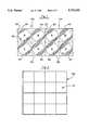
- FIG. 1is an illustration of two pixels showing the red, green, and blue colored lenses.
- FIG. 2sets forth a four-by-four pixel module of the present invention.
- FIG. 3sets forth the schematic for the control of phase-delayed power delivered to the two-pixel arrangement of FIG. 1.
- FIG. 4graphically illustrates the delivery of phase-delayed power to an incandescent bulb.
- FIG. 5is a block diagram setting forth the components of the dual pixel phase-delayed power control of the present invention.
- FIG. 6is a block diagram setting forth the components of the processor and interface cards of the present invention.
- FIG. 7shows the cascading of phase-delayed power controls together in a row of pixels.
- FIG. 8sets forth the timing relationship in a phase-delayed power control.
- FIG. 9sets forth the block diagram of the FIFO interface card of the present invention.
- FIG. 1illustrated two pixels 10a and 10b of the present invention.
- Each pixel 10has four circular lighted areas 20 set in a darkened opaque background 30.
- each lighted area 20has a colored lens, not shown, corresponding to the designated colors.
- Each pixel 10has two blue (B), one red (R), and one green (G) circular lens. These colors mix together to produce the desired color coming from the pixel 10. Colored lights blend and form new colors through addition of colors. Hence, the color white is created from blue, green, and red. Yellow light, for example, is created from green and red.
- the present inventionutilizes two blue lens of the same tint in each pixel 10 without using white. The reason for this is explained next.
- the color bluehas short wavelengths, green has middle wavelengths, and red has long wavelengths. Incandescent bulbs do not create blue light well. Furthermore, the average person has greater difficulty in perceiving the color blue when compared to the colors red or green, especially outdoors. It is well known that the color blue must have greater intensity in incandescent displays. This is accomplished, under the teachings of the present invention, by providing twice the spatial area 20 in each pixel 10 in comparison to red and green. In conventional four-bulb pixels, the following colors are used: white, blue, red, and green. In outdoor displays, the white color washes out the other colors. Under the teachings of the present invention, the use of two blue spatial areas of the same tint achieves true coloring.
- each color blue, red, and greencan have 256 levels of brightness (gray levels) so as to achieve an overall set of color combinations of 256 3 or 16,777,216 possible color combinations.
- Each lens 40is circular, fitting the spatial area 20, and is of the same design and thickness, contrary to the '527 patent set forth above.
- 65,536are selected to provide a true color representation.
- each pixelis on four-inch centers (vertically and horizontally).
- each spatial areais on two-inch centers.
- each module 50is sixteen inches by sixteen inches.
- each pixel 10has four incandescent bulbs 70, which in the preferred embodiment are xenon bulbs rated at five watts at 13.8 volts. It is to be understood that a colored pixel requires only three colors: red, green, and blue. Hence, under the teachings of the present invention, a pixel would have at least three lamps. Xenon bulbs are inexpensive and long lived. With four bulbs used per pixel, this amounts to about 20 watts, which is far less than conventional incandescent displays, but greater than conventional LED displays.
- Bulbs 70are connected to an alternating current power source, VAC, and are further interconnected over lines 80 to the TRIACS 60.
- Line 80ais connected from green bulb 70a to TRIAC 90a.
- the power input to TRIAC 90ais connected to an alternating current, low voltage source through ground, and the control input to TRIAC 90a is connected through resistor 100a to line 110a.
- a phase-delayed gate signalis applied to line 110a, and the TRIAC 90a then turns on, powering the green bulb 70a.
- the remaining blue, green, and red bulbsare interconnected in an identical arrangement.
- four input lines 110control four TRIACs 90 for controlling the color of the pixel.
- redis controlled by a signal on line 110b
- blueis controlled by signals on lines 110c and 110d. It is possible to have 256 4 color combinations in this design. However, as mentioned, the same power level is delivered to both blue bulbs 70c and 70d, resulting in 256 3 color combinations.
- FIG. 4the operation of a TRIAC 90 in conjunction with a bulb is set forth.
- the alternating current voltage sourceis delivered on line 110 to each TRIAC 90.
- the voltage curve 400is shown for a single cycle.
- 256 phase triggering positions 420exist between each set of zero-crossing points (for example 410a and 410b). These triggering positions 420 are evenly spaced between 0 and 180 degrees. Assume the power delivered to the bulb 70 is desired to be at 50%.
- FIG. 4the alternating current voltage source is delivered on line 110 to each TRIAC 90.
- the voltage curve 400is shown for a single cycle.
- 256 phase triggering positions 420exist between each set of zero-crossing points (for example 410a and 410b), 256 phase triggering positions 420 exist. These triggering positions 420 are evenly spaced between 0 and 180 degrees. Assume the power delivered to the bulb 70 is desired
- the TRIAC 90is turned on at step 127 (midway between 0 and 256) so that the phase-delayed power shown by the shaded portion 430 is delivered to the bulb 70.
- the signal on line 110is a phase trigger signal designed to trigger between the zero-crossing points. It can be easily observed that each bulb 70 (or in the case of blue the two connected bulbs) can have its intensity varied at 256 separate levels fully dependent on the phase-delayed power 430 delivered to the bulb 70.
- the level 0corresponds to no light intensity in a bulb and the level 255 corresponds to full light intensity.
- the application specific integrated circuit (ASIC) of the present inventionfor controlling the TRIACs 90 is shown.
- This chipresides on the module 50 of the display and controls two pixels.
- a shift register 500is utilized to receive data serially shifted in at high speeds on line 510. The shifting occurs through use of clock pulses on line 520. In this design, 64 bits are shifted into the shift register 500. Once complete, the 64 data bits are delivered over a parallel connection 530 to a latch 540. Latching occurs by means of a latch-in signal on line 550. The data is latched and continually controls the power delivered to the bulbs until new data is latched in.
- the 64-bit latch 540is interconnected with a series of up counters 560.
- Each up countercontains a byte (8 data bits). Hence, there are eight up counters 560.
- the data in the 64-bit latch 540is delivered over lines 570 into the up counters 560. This is a parallel transfer.
- the value of the byte of informationis loaded into each up counter 560 from the latch 540 with a preset signal appearing on line 580. Once the byte of information has been loaded into each up counter 560, the count pulse on line 590 is utilized to count upwardly from the data value stored in the up counter 560.
- a value of 255would be loaded into the up counter 560a so that a signal immediately appears on line 110a to deliver full power to the bulb 70a (i.e., the count reaches the full count without being incremented). If no power is desired, then a count of zero would be loaded into up counter 560a and the up counter would count 255 pulses to provide a signal just before the zero-crossing 410b. Hence no power would be delivered to the bulb 70a.
- a down countercould also be used wherein the preset value is decremented to zero. In essence, the preset value in the counter is changed until a preselected value is reached (i.e., either 255 or 0).
- FIG. 5a high-speed control for delivering preset phase-delayed power from an AC power source to an incandescent bulb has been disclosed in FIG. 5.
- a conventional computersuch as an IBM-compatible PC 600 contains an industry standard architecture (ISA) bus card 610.
- the bus card 610is designed to write data at the NTSC rate of 30 frames per second to a number of FIFO cards 620 (FIFO 1-FIFO N).
- the datais written over interface bus 630, which in the preferred embodiment is a 16-bit parallel data bus. All of the FIFO interface cards 620 can be fully refreshed in under 15 milliseconds.
- the FIFO interface cards 620are designed to accept 16-bit parallel data from the PC 600 over the bus 630.
- each card 620is designed to have eight FIFO memories 640. Each FIFO memory 640 continually accepts the 16-bit parallel data from the computer 600 until all FIFO memories 640 are filled. When the memories are filled, the data is read out over serial lines 510 to the interconnected pixel rows at a 7.3 MHz rate.
- FIG. 7This is best explained by reference to FIG. 7 and by way of example.
- a displayis 144 pixels wide.
- One row of 144 pixelswould require 36 modules 50 (FIG. 2) arranged horizontally. This is shown in FIG. 7 (P 0 -P 143 ).
- the controller of FIG. 5is shown interconnected and controlling the pixel P (for example, C 0 controls pixel P 0 and pixel P 1 ).
- the controls Care interconnected in daisy chain fashion such that the data appearing on lines 510 is interconnected from one control to the next control.
- the clock signal 520is daisy chained from control to control.
- Each control Crequires 64 bits of data. Hence, for 72 controls, C 1 -C 71 , 576 bytes of data in length are required.
- each byte based on its position in the pixel rowcontrols the intensity of one lamp. This approach does not require individual addressing of the lamps or pixels in a row.
- the shift register 500is loaded, the data byte positions are directly wired to the latch 540.
- each individual FIFO 640in this example, is filled with 576 bytes of data.
- the interface card 620has been completely filled, the data is released to the pixel rows.
- the displaycan be of any height. For example, if the display has 128 pixel rows, then 16 interface cards 620 (each having 8 rows) would be utilized. Each FIFO interface card 620 and each FIFO is separately addressable by the computer 600. This is the only aspect of the present invention that is addressable. There is no requirement to address individual pixels P within a row. Each pixel row has the data bytes arrayed to specifically align with the number of horizontal pixels.
- the interface card 620is designed to contain a known number of rows so that the delivery of the data over the bus 630 into the card 620 is simply a predetermined mapping of data bytes to a known number of rows having a known number of pixels. This provides a simplified design having the capabilities of great speed and updating the intensities of each pixel. Any suitable size of display can easily be designed under the teachings of the present invention.
- FIG. 8The operation of the TRIAC control shown in FIG. 5 is set forth in FIG. 8.
- the zero-crossings 410(FIG. 4) are detected. Circuitry for detecting zero-crossings 410 is well known in the art.
- the zero-crossing pulses 802are shown in wave form 800.
- the preset pulses 810are presented on line 580 of FIG. 5 and are in synchronization with the zero-crossing pulses 800.
- the edge 822is used to gate-in the eight data bit value over bus 570 into the up counter 560.
- the pulse 820presets the up counter so that upon the occurrence of edge 824 the count pulses 830 on line 590 are used to increment the counter 560. These count pulses 830 are continuous until the next zero-crossing 800.
- a trigger signal 840is issued on line 110.
- the pulses 830are not to scale and serve to illustrate the present invention.
- the zero-crossing pulses 802 for 60 Hz ACoccur 120 times per second.
- the preset pulsesoccur 120 times per second and are in synchronism with the zero-crossing pulses 802.
- the counter advance pulses 830 appearing on line 590are also in synchronism with the zero-crossing pulses 802 and deliver count pulses 830 at a frequency of about 40 KHz or pulses every 25 microseconds.
- phase A, B, and CIn AC powered environments, three phase (A, B, and C) power is available.
- the first interface card 620 and its associated pixel rowsmay operate on phase A and sense the zero-crossings for that phase.
- the second cardmay operate on phase B, the third on phase C, the fourth on phase A, etc.
- the present inventionis capable of displaying images at the NTSC standard of 30 frames per second.
- each pixel row of the displayhas its own FIFO 640.
- the preferred embodimenthas eight pixel rows of FIFOs 640 on a card 620.
- the output 510 for each FIFO 640is the data-in line 510 in FIG. 5.
- Each FIFO 640contains the required number of data bytes to be equal to the number of pixel lamps in one row of the sign. Hence, if a row in the sign has 144 pixels, then at 4 bytes per pixel (1 byte per up counter 560), the FIFO 640 is 576 data bytes wide.
- the address decode circuit 900issues an enable over line 910 enabling each FIFO 640 to be addressed and to receive data.
- the Row 1 FIFOis filled first and each FIFO is then filled sequentially until the last row FIFO is filled.
- a new addressappears on bus 630 for another FIFO interface card 620.
- the interface card 620then proceeds to download in serial fashion from the FIFOs for each row simultaneously to their respective rows in the display. This occurs only when the last FIFO (i.e., row eight in FIG. 9) is completely filled.
- the interface card 620has a zero-crossing detect circuit 920 that is interconnected to the AC voltage source over line 930. This conventionally detects zero-crossings and delivers the pulse 840 appearing on line 580 to the up counters 560. The zero-crossing signal on line 580 may also be delivered back to the computer 600 for timing purposes.
- a clock 940that in the preferred embodiment is a 7.3 MHz clock, although any suitable clock source greater than 6 MHz could be used under the teachings of the present invention.
- the clock pulses at 7.3 MHzare delivered over lines 520 as pulses 800.
- the necessary data bytes stored in the FIFO 640are serially delivered into all of the interconnected 64-bit shift registers 500 for the entire pixel row.
- the latch-in signal on line 550latches all of the data from the shift register into the 64-bit latch 540.
- All data bytes in the FIFOs for Rows 1-8are delivered simultaneously and not sequentially. In this fashion, eight rows of pixels in the display are updated simultaneously.
- the interface card 620is then ready to receive new data from the computer 600 over bus 630. It is be observed that no addressing of a pixel is required.
- FIG. 10sets forth another aspect of the present invention pertaining to the selection of level for the phase-delayed power.
- the following levelsare used:
- each incandescent bulb 70can have 256 levels of intensity. However, 32 gray levels are used for red and for blue and 64 gray levels are used for green. Hence, a total of 65,536 (32 ⁇ 32 ⁇ 64) colors are achieved in the preferred embodiment. This is an optional feature of the present invention since the present invention is capable of 256 gray levels at each bulb 700. However, the above levels are selected to provide a true color display with vivid colors. It is to be kept in mind that the blue color as shown in FIG. 1 has twice the spatial area of red and green.
- Xenon incandescent bulbsas is true of all incandescent bulbs having filaments, have characteristic light outputs.
- the goal of the present invention in this optional embodimentis to match the incoming image gray level data to a desired phase level delivered into the up counter 560.
- the goalis to have discrete phase-delayed power levels that provide a linear color intensity output from each colored pixel. Under the teachings of the present invention, this is determined empirically by using a light meter to measure the light intensity from the xenon bulb for each of the 256 delayed power phase data values.
- the linearization of light levelsoccurs as follows.
- the actual light output characteristics of a phase-controlled lampdo not vary linearly with time delay or phase shift delay.
- To compensate for this non-linearityonly those values from the set of 256 values established by an actual plot of the lamp characteristics that most closely match the desired linear light level (one of 32 or 64 levels), where the maximum level is a percentage of the actual maximum light available, are chosen.
- the percentage of maximumis established by either brilliance selection or hue adjustment or both.
Landscapes
- Engineering & Computer Science (AREA)
- Physics & Mathematics (AREA)
- Computer Hardware Design (AREA)
- General Physics & Mathematics (AREA)
- Theoretical Computer Science (AREA)
- Control Of Indicators Other Than Cathode Ray Tubes (AREA)
Abstract
Description
______________________________________ Red 32 levels Green 64 levels Blue 32 levels ______________________________________
Claims (15)
Priority Applications (3)
| Application Number | Priority Date | Filing Date | Title |
|---|---|---|---|
| US08/516,882US5712650A (en) | 1995-06-22 | 1995-08-18 | Large incandescent live image display system |
| AU66375/96AAU6637596A (en) | 1995-08-18 | 1996-07-25 | Large incandescent live image display system |
| PCT/US1996/012227WO1997007493A1 (en) | 1995-08-18 | 1996-07-25 | Large incandescent live image display system |
Applications Claiming Priority (2)
| Application Number | Priority Date | Filing Date | Title |
|---|---|---|---|
| US42995P | 1995-06-22 | 1995-06-22 | |
| US08/516,882US5712650A (en) | 1995-06-22 | 1995-08-18 | Large incandescent live image display system |
Publications (1)
| Publication Number | Publication Date |
|---|---|
| US5712650Atrue US5712650A (en) | 1998-01-27 |
Family
ID=24057486
Family Applications (1)
| Application Number | Title | Priority Date | Filing Date |
|---|---|---|---|
| US08/516,882Expired - Fee RelatedUS5712650A (en) | 1995-06-22 | 1995-08-18 | Large incandescent live image display system |
Country Status (3)
| Country | Link |
|---|---|
| US (1) | US5712650A (en) |
| AU (1) | AU6637596A (en) |
| WO (1) | WO1997007493A1 (en) |
Cited By (79)
| Publication number | Priority date | Publication date | Assignee | Title |
|---|---|---|---|---|
| US5956003A (en)* | 1996-07-24 | 1999-09-21 | Hypres, Inc. | Flat panel display with array of micromachined incandescent lamps |
| US6262698B1 (en)* | 1997-02-06 | 2001-07-17 | Dieter W. Blum | Method and apparatus for display sign |
| US20010028227A1 (en)* | 1997-08-26 | 2001-10-11 | Ihor Lys | Data delivery track |
| US6313344B1 (en) | 1998-05-27 | 2001-11-06 | Bayer Aktiengesellschaft | Organic compounds |
| US20020021269A1 (en)* | 2000-08-07 | 2002-02-21 | Rast Rodger H. | System and method of driving an array of optical elements |
| US20020070688A1 (en)* | 1997-08-26 | 2002-06-13 | Dowling Kevin J. | Light-emitting diode based products |
| US20020101197A1 (en)* | 1997-08-26 | 2002-08-01 | Lys Ihor A. | Packaged information systems |
| US20030057890A1 (en)* | 1997-08-26 | 2003-03-27 | Lys Ihor A. | Systems and methods for controlling illumination sources |
| US20030133292A1 (en)* | 1999-11-18 | 2003-07-17 | Mueller George G. | Methods and apparatus for generating and modulating white light illumination conditions |
| US20030137258A1 (en)* | 1997-08-26 | 2003-07-24 | Colin Piepgras | Light emitting diode based products |
| US20040052076A1 (en)* | 1997-08-26 | 2004-03-18 | Mueller George G. | Controlled lighting methods and apparatus |
| US6717376B2 (en) | 1997-08-26 | 2004-04-06 | Color Kinetics, Incorporated | Automotive information systems |
| US20040105261A1 (en)* | 1997-12-17 | 2004-06-03 | Color Kinetics, Incorporated | Methods and apparatus for generating and modulating illumination conditions |
| US20040130909A1 (en)* | 2002-10-03 | 2004-07-08 | Color Kinetics Incorporated | Methods and apparatus for illuminating environments |
| US20040141321A1 (en)* | 2002-11-20 | 2004-07-22 | Color Kinetics, Incorporated | Lighting and other perceivable effects for toys and other consumer products |
| US20040155609A1 (en)* | 1997-12-17 | 2004-08-12 | Color Kinetics, Incorporated | Data delivery track |
| US6777891B2 (en) | 1997-08-26 | 2004-08-17 | Color Kinetics, Incorporated | Methods and apparatus for controlling devices in a networked lighting system |
| US20040160199A1 (en)* | 2001-05-30 | 2004-08-19 | Color Kinetics, Inc. | Controlled lighting methods and apparatus |
| US6788011B2 (en) | 1997-08-26 | 2004-09-07 | Color Kinetics, Incorporated | Multicolored LED lighting method and apparatus |
| US20040212321A1 (en)* | 2001-03-13 | 2004-10-28 | Lys Ihor A | Methods and apparatus for providing power to lighting devices |
| US20040212993A1 (en)* | 1997-08-26 | 2004-10-28 | Color Kinetics, Inc. | Methods and apparatus for controlling illumination |
| US20040212320A1 (en)* | 1997-08-26 | 2004-10-28 | Dowling Kevin J. | Systems and methods of generating control signals |
| US20050063194A1 (en)* | 1997-08-26 | 2005-03-24 | Color Kinetics, Incorporated | Vehicle lighting methods and apparatus |
| US20050128751A1 (en)* | 2003-05-05 | 2005-06-16 | Color Kinetics, Incorporated | Lighting methods and systems |
| US20050236998A1 (en)* | 1997-08-26 | 2005-10-27 | Color Kinetics, Inc. | Light emitting diode based products |
| US20050253533A1 (en)* | 2002-05-09 | 2005-11-17 | Color Kinetics Incorporated | Dimmable LED-based MR16 lighting apparatus methods |
| US20060181653A1 (en)* | 2005-02-16 | 2006-08-17 | Texas Instruments Incorporated | System and method for increasing bit-depth in a video display system using a pulsed lamp |
| US7113541B1 (en) | 1997-08-26 | 2006-09-26 | Color Kinetics Incorporated | Method for software driven generation of multiple simultaneous high speed pulse width modulated signals |
| US7186003B2 (en) | 1997-08-26 | 2007-03-06 | Color Kinetics Incorporated | Light-emitting diode based products |
| US7242152B2 (en) | 1997-08-26 | 2007-07-10 | Color Kinetics Incorporated | Systems and methods of controlling light systems |
| US7303300B2 (en) | 2000-09-27 | 2007-12-04 | Color Kinetics Incorporated | Methods and systems for illuminating household products |
| US7309965B2 (en) | 1997-08-26 | 2007-12-18 | Color Kinetics Incorporated | Universal lighting network methods and systems |
| US7352339B2 (en) | 1997-08-26 | 2008-04-01 | Philips Solid-State Lighting Solutions | Diffuse illumination systems and methods |
| US7385359B2 (en) | 1997-08-26 | 2008-06-10 | Philips Solid-State Lighting Solutions, Inc. | Information systems |
| US7598684B2 (en) | 2001-05-30 | 2009-10-06 | Philips Solid-State Lighting Solutions, Inc. | Methods and apparatus for controlling devices in a networked lighting system |
| US7598686B2 (en) | 1997-12-17 | 2009-10-06 | Philips Solid-State Lighting Solutions, Inc. | Organic light emitting diode methods and apparatus |
| US7642730B2 (en) | 2000-04-24 | 2010-01-05 | Philips Solid-State Lighting Solutions, Inc. | Methods and apparatus for conveying information via color of light |
| US20100219988A1 (en)* | 2009-03-02 | 2010-09-02 | Griffith Gregory M | Aircraft collision avoidance system |
| US7926975B2 (en) | 2007-12-21 | 2011-04-19 | Altair Engineering, Inc. | Light distribution using a light emitting diode assembly |
| US7938562B2 (en) | 2008-10-24 | 2011-05-10 | Altair Engineering, Inc. | Lighting including integral communication apparatus |
| US7946729B2 (en) | 2008-07-31 | 2011-05-24 | Altair Engineering, Inc. | Fluorescent tube replacement having longitudinally oriented LEDs |
| US7976196B2 (en) | 2008-07-09 | 2011-07-12 | Altair Engineering, Inc. | Method of forming LED-based light and resulting LED-based light |
| US20110234076A1 (en)* | 2010-03-26 | 2011-09-29 | Altair Engineering, Inc. | Inside-out led bulb |
| US8118447B2 (en) | 2007-12-20 | 2012-02-21 | Altair Engineering, Inc. | LED lighting apparatus with swivel connection |
| US8214084B2 (en) | 2008-10-24 | 2012-07-03 | Ilumisys, Inc. | Integration of LED lighting with building controls |
| US8256924B2 (en) | 2008-09-15 | 2012-09-04 | Ilumisys, Inc. | LED-based light having rapidly oscillating LEDs |
| US8299695B2 (en) | 2009-06-02 | 2012-10-30 | Ilumisys, Inc. | Screw-in LED bulb comprising a base having outwardly projecting nodes |
| US8324817B2 (en) | 2008-10-24 | 2012-12-04 | Ilumisys, Inc. | Light and light sensor |
| US8330381B2 (en) | 2009-05-14 | 2012-12-11 | Ilumisys, Inc. | Electronic circuit for DC conversion of fluorescent lighting ballast |
| US8362710B2 (en) | 2009-01-21 | 2013-01-29 | Ilumisys, Inc. | Direct AC-to-DC converter for passive component minimization and universal operation of LED arrays |
| US8360599B2 (en) | 2008-05-23 | 2013-01-29 | Ilumisys, Inc. | Electric shock resistant L.E.D. based light |
| US8421366B2 (en) | 2009-06-23 | 2013-04-16 | Ilumisys, Inc. | Illumination device including LEDs and a switching power control system |
| US8444292B2 (en) | 2008-10-24 | 2013-05-21 | Ilumisys, Inc. | End cap substitute for LED-based tube replacement light |
| US8454193B2 (en) | 2010-07-08 | 2013-06-04 | Ilumisys, Inc. | Independent modules for LED fluorescent light tube replacement |
| US8523394B2 (en) | 2010-10-29 | 2013-09-03 | Ilumisys, Inc. | Mechanisms for reducing risk of shock during installation of light tube |
| US8541958B2 (en) | 2010-03-26 | 2013-09-24 | Ilumisys, Inc. | LED light with thermoelectric generator |
| US8556452B2 (en) | 2009-01-15 | 2013-10-15 | Ilumisys, Inc. | LED lens |
| US8596813B2 (en) | 2010-07-12 | 2013-12-03 | Ilumisys, Inc. | Circuit board mount for LED light tube |
| US8653984B2 (en) | 2008-10-24 | 2014-02-18 | Ilumisys, Inc. | Integration of LED lighting control with emergency notification systems |
| US8664880B2 (en) | 2009-01-21 | 2014-03-04 | Ilumisys, Inc. | Ballast/line detection circuit for fluorescent replacement lamps |
| US8674626B2 (en) | 2008-09-02 | 2014-03-18 | Ilumisys, Inc. | LED lamp failure alerting system |
| US8866396B2 (en) | 2000-02-11 | 2014-10-21 | Ilumisys, Inc. | Light tube and power supply circuit |
| US8870415B2 (en) | 2010-12-09 | 2014-10-28 | Ilumisys, Inc. | LED fluorescent tube replacement light with reduced shock hazard |
| US8901823B2 (en) | 2008-10-24 | 2014-12-02 | Ilumisys, Inc. | Light and light sensor |
| US9057493B2 (en) | 2010-03-26 | 2015-06-16 | Ilumisys, Inc. | LED light tube with dual sided light distribution |
| US9072171B2 (en) | 2011-08-24 | 2015-06-30 | Ilumisys, Inc. | Circuit board mount for LED light |
| US9163794B2 (en) | 2012-07-06 | 2015-10-20 | Ilumisys, Inc. | Power supply assembly for LED-based light tube |
| US9184518B2 (en) | 2012-03-02 | 2015-11-10 | Ilumisys, Inc. | Electrical connector header for an LED-based light |
| US9222645B2 (en) | 2010-11-29 | 2015-12-29 | RTC Industries, Incorporated | LED lighting assembly and method of lighting for a merchandise display |
| US9271367B2 (en) | 2012-07-09 | 2016-02-23 | Ilumisys, Inc. | System and method for controlling operation of an LED-based light |
| US9267650B2 (en) | 2013-10-09 | 2016-02-23 | Ilumisys, Inc. | Lens for an LED-based light |
| US9285084B2 (en) | 2013-03-14 | 2016-03-15 | Ilumisys, Inc. | Diffusers for LED-based lights |
| US20160125800A1 (en)* | 2014-10-31 | 2016-05-05 | Lg Display Co., Ltd. | Display Device, Electronic Appliance Including the Same, and External Power Supply Device |
| US9510400B2 (en) | 2014-05-13 | 2016-11-29 | Ilumisys, Inc. | User input systems for an LED-based light |
| US9574717B2 (en) | 2014-01-22 | 2017-02-21 | Ilumisys, Inc. | LED-based light with addressed LEDs |
| US10161568B2 (en) | 2015-06-01 | 2018-12-25 | Ilumisys, Inc. | LED-based light with canted outer walls |
| US10321528B2 (en) | 2007-10-26 | 2019-06-11 | Philips Lighting Holding B.V. | Targeted content delivery using outdoor lighting networks (OLNs) |
| US11274808B2 (en) | 2010-06-17 | 2022-03-15 | Rtc Industries, Inc. | LED lighting assembly and method of lighting for a merchandise display |
| US11682313B2 (en) | 2021-03-17 | 2023-06-20 | Gregory M. Griffith | Sensor assembly for use in association with aircraft collision avoidance system and method of using the same |
Families Citing this family (2)
| Publication number | Priority date | Publication date | Assignee | Title |
|---|---|---|---|---|
| AUPN766296A0 (en)* | 1996-01-22 | 1996-02-15 | Endogad Research Pty Limited | Trocar and introducing kit |
| AU5276899A (en)* | 1998-09-03 | 2000-03-27 | Yingui Zhou | Method and apparatus of spot scan image |
Citations (11)
| Publication number | Priority date | Publication date | Assignee | Title |
|---|---|---|---|---|
| US3728714A (en)* | 1971-03-11 | 1973-04-17 | Stewart Warner Corp | Non-flickering display system having multi-phase power source |
| US3961365A (en)* | 1974-10-24 | 1976-06-01 | Stewart-Warner Corporation | Color display device |
| US4396869A (en)* | 1979-03-05 | 1983-08-02 | Leviton Manufacturing Company, Inc. | Time responsive variable voltage power supply |
| US4782336A (en)* | 1983-07-26 | 1988-11-01 | Ferrnati, Plc | Two dimensional visual display |
| US4843527A (en)* | 1988-01-07 | 1989-06-27 | American Sign & Indicator Corporation | Matrix lamp bank display and light filtering assembly |
| US5027112A (en)* | 1985-08-20 | 1991-06-25 | Ran Data Pty. Ltd. | Graphic display systems |
| US5198803A (en)* | 1990-06-06 | 1993-03-30 | Opto Tech Corporation | Large scale movie display system with multiple gray levels |
| US5321417A (en)* | 1991-08-28 | 1994-06-14 | Daktronics, Inc. | Visual display panel |
| US5410328A (en)* | 1994-03-28 | 1995-04-25 | Trans-Lux Corporation | Replaceable intelligent pixel module for large-scale LED displays |
| US5420482A (en)* | 1993-02-11 | 1995-05-30 | Phares; Louis A. | Controlled lighting system |
| US5561351A (en)* | 1992-10-14 | 1996-10-01 | Diablo Research Corporation | Dimmer for electrodeless discharge lamp |
- 1995
- 1995-08-18USUS08/516,882patent/US5712650A/ennot_activeExpired - Fee Related
- 1996
- 1996-07-25AUAU66375/96Apatent/AU6637596A/ennot_activeAbandoned
- 1996-07-25WOPCT/US1996/012227patent/WO1997007493A1/enactiveApplication Filing
Patent Citations (11)
| Publication number | Priority date | Publication date | Assignee | Title |
|---|---|---|---|---|
| US3728714A (en)* | 1971-03-11 | 1973-04-17 | Stewart Warner Corp | Non-flickering display system having multi-phase power source |
| US3961365A (en)* | 1974-10-24 | 1976-06-01 | Stewart-Warner Corporation | Color display device |
| US4396869A (en)* | 1979-03-05 | 1983-08-02 | Leviton Manufacturing Company, Inc. | Time responsive variable voltage power supply |
| US4782336A (en)* | 1983-07-26 | 1988-11-01 | Ferrnati, Plc | Two dimensional visual display |
| US5027112A (en)* | 1985-08-20 | 1991-06-25 | Ran Data Pty. Ltd. | Graphic display systems |
| US4843527A (en)* | 1988-01-07 | 1989-06-27 | American Sign & Indicator Corporation | Matrix lamp bank display and light filtering assembly |
| US5198803A (en)* | 1990-06-06 | 1993-03-30 | Opto Tech Corporation | Large scale movie display system with multiple gray levels |
| US5321417A (en)* | 1991-08-28 | 1994-06-14 | Daktronics, Inc. | Visual display panel |
| US5561351A (en)* | 1992-10-14 | 1996-10-01 | Diablo Research Corporation | Dimmer for electrodeless discharge lamp |
| US5420482A (en)* | 1993-02-11 | 1995-05-30 | Phares; Louis A. | Controlled lighting system |
| US5410328A (en)* | 1994-03-28 | 1995-04-25 | Trans-Lux Corporation | Replaceable intelligent pixel module for large-scale LED displays |
Cited By (194)
| Publication number | Priority date | Publication date | Assignee | Title |
|---|---|---|---|---|
| US5956003A (en)* | 1996-07-24 | 1999-09-21 | Hypres, Inc. | Flat panel display with array of micromachined incandescent lamps |
| US6262698B1 (en)* | 1997-02-06 | 2001-07-17 | Dieter W. Blum | Method and apparatus for display sign |
| US7462997B2 (en) | 1997-08-26 | 2008-12-09 | Philips Solid-State Lighting Solutions, Inc. | Multicolored LED lighting method and apparatus |
| US7064498B2 (en) | 1997-08-26 | 2006-06-20 | Color Kinetics Incorporated | Light-emitting diode based products |
| US20010028227A1 (en)* | 1997-08-26 | 2001-10-11 | Ihor Lys | Data delivery track |
| US20020070688A1 (en)* | 1997-08-26 | 2002-06-13 | Dowling Kevin J. | Light-emitting diode based products |
| US20020101197A1 (en)* | 1997-08-26 | 2002-08-01 | Lys Ihor A. | Packaged information systems |
| US20030011538A1 (en)* | 1997-08-26 | 2003-01-16 | Lys Ihor A. | Linear lighting apparatus and methods |
| US20030057890A1 (en)* | 1997-08-26 | 2003-03-27 | Lys Ihor A. | Systems and methods for controlling illumination sources |
| US7845823B2 (en) | 1997-08-26 | 2010-12-07 | Philips Solid-State Lighting Solutions, Inc. | Controlled lighting methods and apparatus |
| US20030137258A1 (en)* | 1997-08-26 | 2003-07-24 | Colin Piepgras | Light emitting diode based products |
| US20050062440A1 (en)* | 1997-08-26 | 2005-03-24 | Color Kinetics, Inc. | Systems and methods for controlling illumination sources |
| US20040052076A1 (en)* | 1997-08-26 | 2004-03-18 | Mueller George G. | Controlled lighting methods and apparatus |
| US6717376B2 (en) | 1997-08-26 | 2004-04-06 | Color Kinetics, Incorporated | Automotive information systems |
| US6720745B2 (en) | 1997-08-26 | 2004-04-13 | Color Kinetics, Incorporated | Data delivery track |
| US7242152B2 (en) | 1997-08-26 | 2007-07-10 | Color Kinetics Incorporated | Systems and methods of controlling light systems |
| US7659674B2 (en) | 1997-08-26 | 2010-02-09 | Philips Solid-State Lighting Solutions, Inc. | Wireless lighting control methods and apparatus |
| US7221104B2 (en) | 1997-08-26 | 2007-05-22 | Color Kinetics Incorporated | Linear lighting apparatus and methods |
| US7253566B2 (en) | 1997-08-26 | 2007-08-07 | Color Kinetics Incorporated | Methods and apparatus for controlling devices in a networked lighting system |
| US6777891B2 (en) | 1997-08-26 | 2004-08-17 | Color Kinetics, Incorporated | Methods and apparatus for controlling devices in a networked lighting system |
| US7525254B2 (en) | 1997-08-26 | 2009-04-28 | Philips Solid-State Lighting Solutions, Inc. | Vehicle lighting methods and apparatus |
| US6788011B2 (en) | 1997-08-26 | 2004-09-07 | Color Kinetics, Incorporated | Multicolored LED lighting method and apparatus |
| US20040178751A1 (en)* | 1997-08-26 | 2004-09-16 | Color Kinetics, Incorporated | Multicolored lighting method and apparatus |
| US6806659B1 (en) | 1997-08-26 | 2004-10-19 | Color Kinetics, Incorporated | Multicolored LED lighting method and apparatus |
| US7186003B2 (en) | 1997-08-26 | 2007-03-06 | Color Kinetics Incorporated | Light-emitting diode based products |
| US20040212993A1 (en)* | 1997-08-26 | 2004-10-28 | Color Kinetics, Inc. | Methods and apparatus for controlling illumination |
| US20040212320A1 (en)* | 1997-08-26 | 2004-10-28 | Dowling Kevin J. | Systems and methods of generating control signals |
| US20040240890A1 (en)* | 1997-08-26 | 2004-12-02 | Color Kinetics, Inc. | Methods and apparatus for controlling devices in a networked lighting system |
| US20070195526A1 (en)* | 1997-08-26 | 2007-08-23 | Color Kinetics Incorporated | Wireless lighting control methods and apparatus |
| US7161311B2 (en) | 1997-08-26 | 2007-01-09 | Color Kinetics Incorporated | Multicolored LED lighting method and apparatus |
| US20030214259A9 (en)* | 1997-08-26 | 2003-11-20 | Dowling Kevin J. | Light-emitting diode based products |
| US20050063194A1 (en)* | 1997-08-26 | 2005-03-24 | Color Kinetics, Incorporated | Vehicle lighting methods and apparatus |
| US6897624B2 (en) | 1997-08-26 | 2005-05-24 | Color Kinetics, Incorporated | Packaged information systems |
| US7427840B2 (en) | 1997-08-26 | 2008-09-23 | Philips Solid-State Lighting Solutions, Inc. | Methods and apparatus for controlling illumination |
| US20050151489A1 (en)* | 1997-08-26 | 2005-07-14 | Color Kinetics Incorporated | Marketplace illumination methods and apparatus |
| US20050236998A1 (en)* | 1997-08-26 | 2005-10-27 | Color Kinetics, Inc. | Light emitting diode based products |
| US6965205B2 (en) | 1997-08-26 | 2005-11-15 | Color Kinetics Incorporated | Light emitting diode based products |
| US7453217B2 (en) | 1997-08-26 | 2008-11-18 | Philips Solid-State Lighting Solutions, Inc. | Marketplace illumination methods and apparatus |
| US6975079B2 (en) | 1997-08-26 | 2005-12-13 | Color Kinetics Incorporated | Systems and methods for controlling illumination sources |
| US7274160B2 (en) | 1997-08-26 | 2007-09-25 | Color Kinetics Incorporated | Multicolored lighting method and apparatus |
| US7385359B2 (en) | 1997-08-26 | 2008-06-10 | Philips Solid-State Lighting Solutions, Inc. | Information systems |
| US7352339B2 (en) | 1997-08-26 | 2008-04-01 | Philips Solid-State Lighting Solutions | Diffuse illumination systems and methods |
| US7135824B2 (en) | 1997-08-26 | 2006-11-14 | Color Kinetics Incorporated | Systems and methods for controlling illumination sources |
| US7231060B2 (en) | 1997-08-26 | 2007-06-12 | Color Kinetics Incorporated | Systems and methods of generating control signals |
| US7113541B1 (en) | 1997-08-26 | 2006-09-26 | Color Kinetics Incorporated | Method for software driven generation of multiple simultaneous high speed pulse width modulated signals |
| US7309965B2 (en) | 1997-08-26 | 2007-12-18 | Color Kinetics Incorporated | Universal lighting network methods and systems |
| US20060152172A9 (en)* | 1997-12-17 | 2006-07-13 | Color Kinetics, Inc. | Methods and apparatus for generating and modulating white light illumination conditions |
| US7132804B2 (en) | 1997-12-17 | 2006-11-07 | Color Kinetics Incorporated | Data delivery track |
| US20060109649A1 (en)* | 1997-12-17 | 2006-05-25 | Color Kinetics Incorporated | Methods and apparatus for controlling a color temperature of lighting conditions |
| US20060012987A9 (en)* | 1997-12-17 | 2006-01-19 | Color Kinetics, Incorporated | Methods and apparatus for generating and modulating illumination conditions |
| US7387405B2 (en) | 1997-12-17 | 2008-06-17 | Philips Solid-State Lighting Solutions, Inc. | Methods and apparatus for generating prescribed spectrums of light |
| US7520634B2 (en) | 1997-12-17 | 2009-04-21 | Philips Solid-State Lighting Solutions, Inc. | Methods and apparatus for controlling a color temperature of lighting conditions |
| US20040155609A1 (en)* | 1997-12-17 | 2004-08-12 | Color Kinetics, Incorporated | Data delivery track |
| US7598686B2 (en) | 1997-12-17 | 2009-10-06 | Philips Solid-State Lighting Solutions, Inc. | Organic light emitting diode methods and apparatus |
| US20040105261A1 (en)* | 1997-12-17 | 2004-06-03 | Color Kinetics, Incorporated | Methods and apparatus for generating and modulating illumination conditions |
| US6313344B1 (en) | 1998-05-27 | 2001-11-06 | Bayer Aktiengesellschaft | Organic compounds |
| US20050030744A1 (en)* | 1999-11-18 | 2005-02-10 | Color Kinetics, Incorporated | Methods and apparatus for generating and modulating illumination conditions |
| US7572028B2 (en) | 1999-11-18 | 2009-08-11 | Philips Solid-State Lighting Solutions, Inc. | Methods and apparatus for generating and modulating white light illumination conditions |
| US20050040774A1 (en)* | 1999-11-18 | 2005-02-24 | Color Kinetics, Inc. | Methods and apparatus for generating and modulating white light illumination conditions |
| US20070115658A1 (en)* | 1999-11-18 | 2007-05-24 | Color Kinetics Incorporated | Methods and apparatus for generating and modulating white light illumination conditions |
| US7014336B1 (en) | 1999-11-18 | 2006-03-21 | Color Kinetics Incorporated | Systems and methods for generating and modulating illumination conditions |
| US7255457B2 (en) | 1999-11-18 | 2007-08-14 | Color Kinetics Incorporated | Methods and apparatus for generating and modulating illumination conditions |
| US20070115665A1 (en)* | 1999-11-18 | 2007-05-24 | Color Kinetics Incorporated | Methods and apparatus for generating and modulating white light illumination conditions |
| US20060285325A1 (en)* | 1999-11-18 | 2006-12-21 | Color Kinetics Incorporated | Conventionally-shaped light bulbs employing white leds |
| US7959320B2 (en) | 1999-11-18 | 2011-06-14 | Philips Solid-State Lighting Solutions, Inc. | Methods and apparatus for generating and modulating white light illumination conditions |
| US7350936B2 (en) | 1999-11-18 | 2008-04-01 | Philips Solid-State Lighting Solutions, Inc. | Conventionally-shaped light bulbs employing white LEDs |
| US20030133292A1 (en)* | 1999-11-18 | 2003-07-17 | Mueller George G. | Methods and apparatus for generating and modulating white light illumination conditions |
| US10557593B2 (en) | 2000-02-11 | 2020-02-11 | Ilumisys, Inc. | Light tube and power supply circuit |
| US8870412B1 (en) | 2000-02-11 | 2014-10-28 | Ilumisys, Inc. | Light tube and power supply circuit |
| US9222626B1 (en) | 2000-02-11 | 2015-12-29 | Ilumisys, Inc. | Light tube and power supply circuit |
| US9803806B2 (en) | 2000-02-11 | 2017-10-31 | Ilumisys, Inc. | Light tube and power supply circuit |
| US9006990B1 (en) | 2000-02-11 | 2015-04-14 | Ilumisys, Inc. | Light tube and power supply circuit |
| US9739428B1 (en) | 2000-02-11 | 2017-08-22 | Ilumisys, Inc. | Light tube and power supply circuit |
| US9006993B1 (en) | 2000-02-11 | 2015-04-14 | Ilumisys, Inc. | Light tube and power supply circuit |
| US9416923B1 (en) | 2000-02-11 | 2016-08-16 | Ilumisys, Inc. | Light tube and power supply circuit |
| US9746139B2 (en) | 2000-02-11 | 2017-08-29 | Ilumisys, Inc. | Light tube and power supply circuit |
| US9970601B2 (en) | 2000-02-11 | 2018-05-15 | Ilumisys, Inc. | Light tube and power supply circuit |
| US9752736B2 (en) | 2000-02-11 | 2017-09-05 | Ilumisys, Inc. | Light tube and power supply circuit |
| US8866396B2 (en) | 2000-02-11 | 2014-10-21 | Ilumisys, Inc. | Light tube and power supply circuit |
| US9759392B2 (en) | 2000-02-11 | 2017-09-12 | Ilumisys, Inc. | Light tube and power supply circuit |
| US10054270B2 (en) | 2000-02-11 | 2018-08-21 | Ilumisys, Inc. | Light tube and power supply circuit |
| US9777893B2 (en) | 2000-02-11 | 2017-10-03 | Ilumisys, Inc. | Light tube and power supply circuit |
| US7642730B2 (en) | 2000-04-24 | 2010-01-05 | Philips Solid-State Lighting Solutions, Inc. | Methods and apparatus for conveying information via color of light |
| US9955541B2 (en) | 2000-08-07 | 2018-04-24 | Philips Lighting Holding B.V. | Universal lighting network methods and systems |
| US20080215391A1 (en)* | 2000-08-07 | 2008-09-04 | Philips Solid-State Lighting Solutions | Universal lighting network methods and systems |
| US20020021269A1 (en)* | 2000-08-07 | 2002-02-21 | Rast Rodger H. | System and method of driving an array of optical elements |
| US7292209B2 (en) | 2000-08-07 | 2007-11-06 | Rastar Corporation | System and method of driving an array of optical elements |
| US20080130267A1 (en)* | 2000-09-27 | 2008-06-05 | Philips Solid-State Lighting Solutions | Methods and systems for illuminating household products |
| US7652436B2 (en) | 2000-09-27 | 2010-01-26 | Philips Solid-State Lighting Solutions, Inc. | Methods and systems for illuminating household products |
| US7303300B2 (en) | 2000-09-27 | 2007-12-04 | Color Kinetics Incorporated | Methods and systems for illuminating household products |
| US20040212321A1 (en)* | 2001-03-13 | 2004-10-28 | Lys Ihor A | Methods and apparatus for providing power to lighting devices |
| US7352138B2 (en) | 2001-03-13 | 2008-04-01 | Philips Solid-State Lighting Solutions, Inc. | Methods and apparatus for providing power to lighting devices |
| US7038399B2 (en) | 2001-03-13 | 2006-05-02 | Color Kinetics Incorporated | Methods and apparatus for providing power to lighting devices |
| US7598681B2 (en) | 2001-05-30 | 2009-10-06 | Philips Solid-State Lighting Solutions, Inc. | Methods and apparatus for controlling devices in a networked lighting system |
| US7202613B2 (en) | 2001-05-30 | 2007-04-10 | Color Kinetics Incorporated | Controlled lighting methods and apparatus |
| US20070291483A1 (en)* | 2001-05-30 | 2007-12-20 | Color Kinetics Incorporated | Controlled lighting methods and apparatus |
| US7598684B2 (en) | 2001-05-30 | 2009-10-06 | Philips Solid-State Lighting Solutions, Inc. | Methods and apparatus for controlling devices in a networked lighting system |
| US7550931B2 (en) | 2001-05-30 | 2009-06-23 | Philips Solid-State Lighting Solutions, Inc. | Controlled lighting methods and apparatus |
| US20040160199A1 (en)* | 2001-05-30 | 2004-08-19 | Color Kinetics, Inc. | Controlled lighting methods and apparatus |
| US20050253533A1 (en)* | 2002-05-09 | 2005-11-17 | Color Kinetics Incorporated | Dimmable LED-based MR16 lighting apparatus methods |
| US7358679B2 (en) | 2002-05-09 | 2008-04-15 | Philips Solid-State Lighting Solutions, Inc. | Dimmable LED-based MR16 lighting apparatus and methods |
| US20040130909A1 (en)* | 2002-10-03 | 2004-07-08 | Color Kinetics Incorporated | Methods and apparatus for illuminating environments |
| US7300192B2 (en) | 2002-10-03 | 2007-11-27 | Color Kinetics Incorporated | Methods and apparatus for illuminating environments |
| US20040141321A1 (en)* | 2002-11-20 | 2004-07-22 | Color Kinetics, Incorporated | Lighting and other perceivable effects for toys and other consumer products |
| US20050128751A1 (en)* | 2003-05-05 | 2005-06-16 | Color Kinetics, Incorporated | Lighting methods and systems |
| US8207821B2 (en) | 2003-05-05 | 2012-06-26 | Philips Solid-State Lighting Solutions, Inc. | Lighting methods and systems |
| US7178941B2 (en) | 2003-05-05 | 2007-02-20 | Color Kinetics Incorporated | Lighting methods and systems |
| US20070145915A1 (en)* | 2003-05-05 | 2007-06-28 | Color Kinetics Incorporated | Lighting methods and systems |
| US20060181653A1 (en)* | 2005-02-16 | 2006-08-17 | Texas Instruments Incorporated | System and method for increasing bit-depth in a video display system using a pulsed lamp |
| US8432339B2 (en)* | 2005-02-16 | 2013-04-30 | Texas Instruments Incorporated | System and method for increasing bit-depth in a video display system using a pulsed lamp |
| US10321528B2 (en) | 2007-10-26 | 2019-06-11 | Philips Lighting Holding B.V. | Targeted content delivery using outdoor lighting networks (OLNs) |
| US8118447B2 (en) | 2007-12-20 | 2012-02-21 | Altair Engineering, Inc. | LED lighting apparatus with swivel connection |
| US8928025B2 (en) | 2007-12-20 | 2015-01-06 | Ilumisys, Inc. | LED lighting apparatus with swivel connection |
| US7926975B2 (en) | 2007-12-21 | 2011-04-19 | Altair Engineering, Inc. | Light distribution using a light emitting diode assembly |
| US8807785B2 (en) | 2008-05-23 | 2014-08-19 | Ilumisys, Inc. | Electric shock resistant L.E.D. based light |
| US8360599B2 (en) | 2008-05-23 | 2013-01-29 | Ilumisys, Inc. | Electric shock resistant L.E.D. based light |
| US7976196B2 (en) | 2008-07-09 | 2011-07-12 | Altair Engineering, Inc. | Method of forming LED-based light and resulting LED-based light |
| US7946729B2 (en) | 2008-07-31 | 2011-05-24 | Altair Engineering, Inc. | Fluorescent tube replacement having longitudinally oriented LEDs |
| US8674626B2 (en) | 2008-09-02 | 2014-03-18 | Ilumisys, Inc. | LED lamp failure alerting system |
| US8256924B2 (en) | 2008-09-15 | 2012-09-04 | Ilumisys, Inc. | LED-based light having rapidly oscillating LEDs |
| US10342086B2 (en) | 2008-10-24 | 2019-07-02 | Ilumisys, Inc. | Integration of LED lighting with building controls |
| US10560992B2 (en) | 2008-10-24 | 2020-02-11 | Ilumisys, Inc. | Light and light sensor |
| US8214084B2 (en) | 2008-10-24 | 2012-07-03 | Ilumisys, Inc. | Integration of LED lighting with building controls |
| US8251544B2 (en) | 2008-10-24 | 2012-08-28 | Ilumisys, Inc. | Lighting including integral communication apparatus |
| US8653984B2 (en) | 2008-10-24 | 2014-02-18 | Ilumisys, Inc. | Integration of LED lighting control with emergency notification systems |
| US9635727B2 (en) | 2008-10-24 | 2017-04-25 | Ilumisys, Inc. | Light and light sensor |
| US11333308B2 (en) | 2008-10-24 | 2022-05-17 | Ilumisys, Inc. | Light and light sensor |
| US10036549B2 (en) | 2008-10-24 | 2018-07-31 | Ilumisys, Inc. | Lighting including integral communication apparatus |
| US8901823B2 (en) | 2008-10-24 | 2014-12-02 | Ilumisys, Inc. | Light and light sensor |
| US11073275B2 (en) | 2008-10-24 | 2021-07-27 | Ilumisys, Inc. | Lighting including integral communication apparatus |
| US8324817B2 (en) | 2008-10-24 | 2012-12-04 | Ilumisys, Inc. | Light and light sensor |
| US8946996B2 (en) | 2008-10-24 | 2015-02-03 | Ilumisys, Inc. | Light and light sensor |
| US8444292B2 (en) | 2008-10-24 | 2013-05-21 | Ilumisys, Inc. | End cap substitute for LED-based tube replacement light |
| US9585216B2 (en) | 2008-10-24 | 2017-02-28 | Ilumisys, Inc. | Integration of LED lighting with building controls |
| US10176689B2 (en) | 2008-10-24 | 2019-01-08 | Ilumisys, Inc. | Integration of led lighting control with emergency notification systems |
| US10973094B2 (en) | 2008-10-24 | 2021-04-06 | Ilumisys, Inc. | Integration of LED lighting with building controls |
| US9101026B2 (en) | 2008-10-24 | 2015-08-04 | Ilumisys, Inc. | Integration of LED lighting with building controls |
| US10932339B2 (en) | 2008-10-24 | 2021-02-23 | Ilumisys, Inc. | Light and light sensor |
| US10713915B2 (en) | 2008-10-24 | 2020-07-14 | Ilumisys, Inc. | Integration of LED lighting control with emergency notification systems |
| US10182480B2 (en) | 2008-10-24 | 2019-01-15 | Ilumisys, Inc. | Light and light sensor |
| US9398661B2 (en) | 2008-10-24 | 2016-07-19 | Ilumisys, Inc. | Light and light sensor |
| US10571115B2 (en) | 2008-10-24 | 2020-02-25 | Ilumisys, Inc. | Lighting including integral communication apparatus |
| US9353939B2 (en) | 2008-10-24 | 2016-05-31 | iLumisys, Inc | Lighting including integral communication apparatus |
| US7938562B2 (en) | 2008-10-24 | 2011-05-10 | Altair Engineering, Inc. | Lighting including integral communication apparatus |
| US8556452B2 (en) | 2009-01-15 | 2013-10-15 | Ilumisys, Inc. | LED lens |
| US8362710B2 (en) | 2009-01-21 | 2013-01-29 | Ilumisys, Inc. | Direct AC-to-DC converter for passive component minimization and universal operation of LED arrays |
| US8664880B2 (en) | 2009-01-21 | 2014-03-04 | Ilumisys, Inc. | Ballast/line detection circuit for fluorescent replacement lamps |
| US8264377B2 (en) | 2009-03-02 | 2012-09-11 | Griffith Gregory M | Aircraft collision avoidance system |
| US8803710B2 (en) | 2009-03-02 | 2014-08-12 | Gregory M. Griffith | Aircraft collision avoidance system |
| US20100219988A1 (en)* | 2009-03-02 | 2010-09-02 | Griffith Gregory M | Aircraft collision avoidance system |
| US10013888B2 (en) | 2009-03-02 | 2018-07-03 | Wingguard, Llc | Aircraft collision avoidance system |
| US10431104B2 (en) | 2009-03-02 | 2019-10-01 | Wingguard, Llc | Aircraft collision avoidance system |
| US8330381B2 (en) | 2009-05-14 | 2012-12-11 | Ilumisys, Inc. | Electronic circuit for DC conversion of fluorescent lighting ballast |
| US8299695B2 (en) | 2009-06-02 | 2012-10-30 | Ilumisys, Inc. | Screw-in LED bulb comprising a base having outwardly projecting nodes |
| US8421366B2 (en) | 2009-06-23 | 2013-04-16 | Ilumisys, Inc. | Illumination device including LEDs and a switching power control system |
| US8540401B2 (en) | 2010-03-26 | 2013-09-24 | Ilumisys, Inc. | LED bulb with internal heat dissipating structures |
| US8541958B2 (en) | 2010-03-26 | 2013-09-24 | Ilumisys, Inc. | LED light with thermoelectric generator |
| US9013119B2 (en) | 2010-03-26 | 2015-04-21 | Ilumisys, Inc. | LED light with thermoelectric generator |
| US8840282B2 (en) | 2010-03-26 | 2014-09-23 | Ilumisys, Inc. | LED bulb with internal heat dissipating structures |
| US9057493B2 (en) | 2010-03-26 | 2015-06-16 | Ilumisys, Inc. | LED light tube with dual sided light distribution |
| US9395075B2 (en) | 2010-03-26 | 2016-07-19 | Ilumisys, Inc. | LED bulb for incandescent bulb replacement with internal heat dissipating structures |
| US20110234076A1 (en)* | 2010-03-26 | 2011-09-29 | Altair Engineering, Inc. | Inside-out led bulb |
| US11274808B2 (en) | 2010-06-17 | 2022-03-15 | Rtc Industries, Inc. | LED lighting assembly and method of lighting for a merchandise display |
| US10619824B2 (en) | 2010-06-17 | 2020-04-14 | Rtc Industries, Inc. | LED lighting assembly and method of lighting for a merchandise display |
| US8454193B2 (en) | 2010-07-08 | 2013-06-04 | Ilumisys, Inc. | Independent modules for LED fluorescent light tube replacement |
| US8596813B2 (en) | 2010-07-12 | 2013-12-03 | Ilumisys, Inc. | Circuit board mount for LED light tube |
| US8894430B2 (en) | 2010-10-29 | 2014-11-25 | Ilumisys, Inc. | Mechanisms for reducing risk of shock during installation of light tube |
| US8523394B2 (en) | 2010-10-29 | 2013-09-03 | Ilumisys, Inc. | Mechanisms for reducing risk of shock during installation of light tube |
| US9829178B2 (en) | 2010-11-29 | 2017-11-28 | Rtc Industries, Inc. | LED lighting assembly and method of lighting for a merchandise display |
| US9222645B2 (en) | 2010-11-29 | 2015-12-29 | RTC Industries, Incorporated | LED lighting assembly and method of lighting for a merchandise display |
| US8870415B2 (en) | 2010-12-09 | 2014-10-28 | Ilumisys, Inc. | LED fluorescent tube replacement light with reduced shock hazard |
| US9072171B2 (en) | 2011-08-24 | 2015-06-30 | Ilumisys, Inc. | Circuit board mount for LED light |
| US9184518B2 (en) | 2012-03-02 | 2015-11-10 | Ilumisys, Inc. | Electrical connector header for an LED-based light |
| US9163794B2 (en) | 2012-07-06 | 2015-10-20 | Ilumisys, Inc. | Power supply assembly for LED-based light tube |
| US9271367B2 (en) | 2012-07-09 | 2016-02-23 | Ilumisys, Inc. | System and method for controlling operation of an LED-based light |
| US10278247B2 (en) | 2012-07-09 | 2019-04-30 | Ilumisys, Inc. | System and method for controlling operation of an LED-based light |
| US9807842B2 (en) | 2012-07-09 | 2017-10-31 | Ilumisys, Inc. | System and method for controlling operation of an LED-based light |
| US10966295B2 (en) | 2012-07-09 | 2021-03-30 | Ilumisys, Inc. | System and method for controlling operation of an LED-based light |
| US9285084B2 (en) | 2013-03-14 | 2016-03-15 | Ilumisys, Inc. | Diffusers for LED-based lights |
| US9267650B2 (en) | 2013-10-09 | 2016-02-23 | Ilumisys, Inc. | Lens for an LED-based light |
| US10260686B2 (en) | 2014-01-22 | 2019-04-16 | Ilumisys, Inc. | LED-based light with addressed LEDs |
| US9574717B2 (en) | 2014-01-22 | 2017-02-21 | Ilumisys, Inc. | LED-based light with addressed LEDs |
| US9510400B2 (en) | 2014-05-13 | 2016-11-29 | Ilumisys, Inc. | User input systems for an LED-based light |
| US10395586B2 (en)* | 2014-10-31 | 2019-08-27 | Lg Display Co., Ltd. | Display device, electronic appliance including the same, and external power supply device |
| CN105575310A (en)* | 2014-10-31 | 2016-05-11 | 乐金显示有限公司 | Display Device, Electronic Appliance Including the Same, and External Power Supply Device |
| US20160125800A1 (en)* | 2014-10-31 | 2016-05-05 | Lg Display Co., Ltd. | Display Device, Electronic Appliance Including the Same, and External Power Supply Device |
| CN105575310B (en)* | 2014-10-31 | 2018-12-11 | 乐金显示有限公司 | Display device, electronic equipment and external powering device including the display device |
| KR20160053269A (en)* | 2014-10-31 | 2016-05-13 | 엘지디스플레이 주식회사 | Display device and electronic appliance of the same, power supplyer |
| US10690296B2 (en) | 2015-06-01 | 2020-06-23 | Ilumisys, Inc. | LED-based light with canted outer walls |
| US11028972B2 (en) | 2015-06-01 | 2021-06-08 | Ilumisys, Inc. | LED-based light with canted outer walls |
| US10161568B2 (en) | 2015-06-01 | 2018-12-25 | Ilumisys, Inc. | LED-based light with canted outer walls |
| US11428370B2 (en) | 2015-06-01 | 2022-08-30 | Ilumisys, Inc. | LED-based light with canted outer walls |
| US11682313B2 (en) | 2021-03-17 | 2023-06-20 | Gregory M. Griffith | Sensor assembly for use in association with aircraft collision avoidance system and method of using the same |
| US12002372B2 (en) | 2021-03-17 | 2024-06-04 | Gregory M. Griffith | Sensor assembly for use in association with aircraft collision avoidance system and method of using the same |
Also Published As
| Publication number | Publication date |
|---|---|
| AU6637596A (en) | 1997-03-12 |
| WO1997007493A1 (en) | 1997-02-27 |
Similar Documents
| Publication | Publication Date | Title |
|---|---|---|
| US5712650A (en) | Large incandescent live image display system | |
| CA1294720C (en) | Display device | |
| ES2273671T3 (en) | FULL COLOR PRESENTATION SYSTEM OF ELECTROLUMINISCENT DIODES. | |
| US5416496A (en) | Ferroelectric liquid crystal display apparatus and method | |
| EP0703560B1 (en) | Visual display system | |
| US5359345A (en) | Shuttered and cycled light emitting diode display and method of producing the same | |
| CN101472369B (en) | Light emission control system and image display system | |
| US6288696B1 (en) | Analog driver for led or similar display element | |
| US20080238950A1 (en) | Illuminating display and weighted-bit driving methods for use with the same | |
| US5225875A (en) | High speed color display system and method of using same | |
| CN101118347A (en) | Liquid crystal display device and its driving method, luminous body and its driving method, and lighting device | |
| KR20050025918A (en) | Configurable large-area display system and control unit used therein, and method of operating the display | |
| US3961365A (en) | Color display device | |
| US5612710A (en) | Real time low cost, large scale array 65K color display using lamps | |
| Liu et al. | The design and implementation of a low-cost 360-degree color LED display system | |
| CN104315453A (en) | Highly-vivid flame lamp and achieving method thereof | |
| WO1997044773A1 (en) | Scroll display method and apparatus | |
| US4646079A (en) | Self-scanning electroluminescent display | |
| CN114863888B (en) | Image display synchronization control system and synchronization control method thereof | |
| JP2713893B2 (en) | Flat panel display | |
| WO1988007249A1 (en) | Display with pseudo-colour pixels | |
| US20060001786A1 (en) | Display device comprising a light guide | |
| EP0238557A1 (en) | Multi-coloured illuminated dynamic display | |
| JP4207252B2 (en) | Display device | |
| CN108806618A (en) | The display screen and display equipment of three primary colours light |
Legal Events
| Date | Code | Title | Description |
|---|---|---|---|
| AS | Assignment | Owner name:MIKOHN GAMING CORPORATION, NEVADA Free format text:ASSIGNMENT OF ASSIGNORS INTEREST;ASSIGNOR:BARLOW, JAMES EDWIN;REEL/FRAME:007679/0178 Effective date:19950815 | |
| FEPP | Fee payment procedure | Free format text:PAYOR NUMBER ASSIGNED (ORIGINAL EVENT CODE: ASPN); ENTITY STATUS OF PATENT OWNER: LARGE ENTITY | |
| AS | Assignment | Owner name:FIRST SOURCE FINANCIAL LLP, ILLINOIS Free format text:SECURITY INTEREST;ASSIGNOR:MIKOHN GAMING CORPORATION;REEL/FRAME:008861/0017 Effective date:19971024 | |
| AS | Assignment | Owner name:FIRST SOURCE FINANCIAL LLP, ILLINOIS Free format text:SECURITY INTEREST;ASSIGNORS:MIKOHN GAMING CORPORATION;MIKOHN NEVADA;MGC, INC.;AND OTHERS;REEL/FRAME:009490/0622 Effective date:19980828 | |
| FPAY | Fee payment | Year of fee payment:4 | |
| AS | Assignment | Owner name:MIKOHN GAMING CORPORATION, NEVADA Free format text:RELEASE OF SECURITY INTEREST IN PATENTS;ASSIGNOR:FIRST SOURCE FINANCIAL, LLP;REEL/FRAME:012506/0670 Effective date:20010822 Owner name:MIKOHN NEVADA, NEVADA Free format text:RELEASE OF SECURITY INTEREST IN PATENTS;ASSIGNOR:FIRST SOURCE FINANCIAL, LLP;REEL/FRAME:012506/0670 Effective date:20010822 Owner name:MGC, INC., NEVADA Free format text:RELEASE OF SECURITY INTEREST IN PATENTS;ASSIGNOR:FIRST SOURCE FINANCIAL, LLP;REEL/FRAME:012506/0670 Effective date:20010822 Owner name:CASINO EXCITEMENT, INC., NEVADA Free format text:RELEASE OF SECURITY INTEREST IN PATENTS;ASSIGNOR:FIRST SOURCE FINANCIAL, LLP;REEL/FRAME:012506/0670 Effective date:20010822 Owner name:PROGRESSIVE GAMES, INC., NEVADA Free format text:RELEASE OF SECURITY INTEREST IN PATENTS;ASSIGNOR:FIRST SOURCE FINANCIAL, LLP;REEL/FRAME:012506/0670 Effective date:20010822 Owner name:FIRSTAR BANK, N.A., MINNESOTA Free format text:SECURITY INTEREST;ASSIGNORS:MIKOHN GAMING CORPORATION;NEVADA, MIKOHN;MGC, INC.;AND OTHERS;REEL/FRAME:012795/0288 Effective date:20010822 | |
| AS | Assignment | Owner name:FOOTHILL CAPITAL CORPORATION, CALIFORNIA Free format text:SECURITY INTEREST;ASSIGNORS:MIKOHN GAMING CORPORATION;CASINO EXCITEMENT, INC.;MGC, INC.;AND OTHERS;REEL/FRAME:013011/0233 Effective date:20020214 | |
| AS | Assignment | Owner name:C.E.I. HOLDING, INC., NEVADA Free format text:ASSIGNMENT OF ASSIGNORS INTEREST;ASSIGNOR:MIKOHN GAMING CORPORATION;REEL/FRAME:013516/0524 Effective date:20021114 | |
| REMI | Maintenance fee reminder mailed | ||
| LAPS | Lapse for failure to pay maintenance fees | ||
| STCH | Information on status: patent discontinuation | Free format text:PATENT EXPIRED DUE TO NONPAYMENT OF MAINTENANCE FEES UNDER 37 CFR 1.362 | |
| FP | Lapsed due to failure to pay maintenance fee | Effective date:20060127 | |
| AS | Assignment | Owner name:MIKOHN NEVADA, NEVADA Free format text:RELEASE BY SECURED PARTY;ASSIGNOR:CAPITALSOURCE FINANCE LLC;REEL/FRAME:017422/0098 Effective date:20060404 Owner name:PROGRESSIVE GAMES, INC., NEVADA Free format text:RELEASE BY SECURED PARTY;ASSIGNOR:CAPITALSOURCE FINANCE LLC;REEL/FRAME:017422/0098 Effective date:20060404 Owner name:MGC, INC., NEVADA Free format text:RELEASE BY SECURED PARTY;ASSIGNOR:CAPITALSOURCE FINANCE LLC;REEL/FRAME:017422/0098 Effective date:20060404 Owner name:MIKOHN INTERNATIONAL, INC., NEVADA Free format text:RELEASE BY SECURED PARTY;ASSIGNOR:CAPITALSOURCE FINANCE LLC;REEL/FRAME:017422/0098 Effective date:20060404 Owner name:GAMES OF NEVADA, INC., NEVADA Free format text:RELEASE BY SECURED PARTY;ASSIGNOR:CAPITALSOURCE FINANCE LLC;REEL/FRAME:017422/0098 Effective date:20060404 Owner name:CASINO EXCITEMENT, INC., NEVADA Free format text:RELEASE BY SECURED PARTY;ASSIGNOR:CAPITALSOURCE FINANCE LLC;REEL/FRAME:017422/0098 Effective date:20060404 Owner name:MIKOHN GAMING CORPORATION, NEVADA Free format text:RELEASE BY SECURED PARTY;ASSIGNOR:CAPITALSOURCE FINANCE LLC;REEL/FRAME:017422/0098 Effective date:20060404 | |
| AS | Assignment | Owner name:CAPITALSOURCE FINANCE LLC, MARYLAND Free format text:ASSIGNMENT OF SECURITY AGREEMENT;ASSIGNOR:WELLS FARGO FOOTHILL, INC.;REEL/FRAME:017435/0256 Effective date:20050502 | |
| AS | Assignment | Owner name:ENDX, INC. (USA), NEVADA Free format text:RELEASE BY SECURED PARTY;ASSIGNOR:U.S. BANK NATIONAL ASSOCIATION (AS SUCCESSOR TRUSTEE TO FIRSTAR BANK, N.A.);REEL/FRAME:021387/0945 Effective date:20080815 Owner name:MIKOHN INTERNATIONAL, INC., NEVADA Free format text:RELEASE BY SECURED PARTY;ASSIGNOR:U.S. BANK NATIONAL ASSOCIATION (AS SUCCESSOR TRUSTEE TO FIRSTAR BANK, N.A.);REEL/FRAME:021387/0945 Effective date:20080815 Owner name:PROGRESSIVE GAMING INTERNATIONAL CORPORATION (F/K/ Free format text:RELEASE BY SECURED PARTY;ASSIGNOR:U.S. BANK NATIONAL ASSOCIATION (AS SUCCESSOR TRUSTEE TO FIRSTAR BANK, N.A.);REEL/FRAME:021387/0945 Effective date:20080815 Owner name:VIKING MERGER SUBSIDIARY, LLC, NEVADA Free format text:RELEASE BY SECURED PARTY;ASSIGNOR:U.S. BANK NATIONAL ASSOCIATION (AS SUCCESSOR TRUSTEE TO FIRSTAR BANK, N.A.);REEL/FRAME:021387/0945 Effective date:20080815 Owner name:GAMES OF NEVADA, INC., NEVADA Free format text:RELEASE BY SECURED PARTY;ASSIGNOR:U.S. BANK NATIONAL ASSOCIATION (AS SUCCESSOR TRUSTEE TO FIRSTAR BANK, N.A.);REEL/FRAME:021387/0945 Effective date:20080815 Owner name:PGIC NV (F/K/A MIKOHN NEVADA), NEVADA Free format text:RELEASE BY SECURED PARTY;ASSIGNOR:U.S. BANK NATIONAL ASSOCIATION (AS SUCCESSOR TRUSTEE TO FIRSTAR BANK, N.A.);REEL/FRAME:021387/0945 Effective date:20080815 Owner name:PROGRESSIVE GAMES, INC., NEVADA Free format text:RELEASE BY SECURED PARTY;ASSIGNOR:U.S. BANK NATIONAL ASSOCIATION (AS SUCCESSOR TRUSTEE TO FIRSTAR BANK, N.A.);REEL/FRAME:021387/0945 Effective date:20080815 Owner name:PRIMELINE GAMING TECHNOLOGIES, INC., NEVADA Free format text:RELEASE BY SECURED PARTY;ASSIGNOR:U.S. BANK NATIONAL ASSOCIATION (AS SUCCESSOR TRUSTEE TO FIRSTAR BANK, N.A.);REEL/FRAME:021387/0945 Effective date:20080815 Owner name:MGC, INC., NEVADA Free format text:RELEASE BY SECURED PARTY;ASSIGNOR:U.S. BANK NATIONAL ASSOCIATION (AS SUCCESSOR TRUSTEE TO FIRSTAR BANK, N.A.);REEL/FRAME:021387/0945 Effective date:20080815 |