US5711762A - Laser surgery apparatus and method - Google Patents
Laser surgery apparatus and methodDownload PDFInfo
- Publication number
- US5711762A US5711762AUS08/474,243US47424395AUS5711762AUS 5711762 AUS5711762 AUS 5711762AUS 47424395 AUS47424395 AUS 47424395AUS 5711762 AUS5711762 AUS 5711762A
- Authority
- US
- United States
- Prior art keywords
- mask
- laser
- cornea
- edge
- center
- Prior art date
- Legal status (The legal status is an assumption and is not a legal conclusion. Google has not performed a legal analysis and makes no representation as to the accuracy of the status listed.)
- Expired - Lifetime
Links
- 238000000034methodMethods0.000titleclaimsabstractdescription28
- 238000002430laser surgeryMethods0.000titleclaimsdescription4
- 230000005855radiationEffects0.000claimsabstractdescription10
- 238000002679ablationMethods0.000claimsabstractdescription4
- 210000004087corneaAnatomy0.000claimsdescription17
- 239000000463materialSubstances0.000claimsdescription7
- 238000001816coolingMethods0.000claimsdescription5
- 230000003287optical effectEffects0.000claimsdescription4
- 229910052751metalInorganic materials0.000claimsdescription3
- 239000002184metalSubstances0.000claimsdescription3
- 229920003023plasticPolymers0.000claimsdescription3
- 239000004033plasticSubstances0.000claimsdescription3
- 229920003229poly(methyl methacrylate)Polymers0.000claimsdescription2
- 229920000642polymerPolymers0.000claimsdescription2
- 239000004926polymethyl methacrylateSubstances0.000claimsdescription2
- 238000009825accumulationMethods0.000claims1
- 238000007493shaping processMethods0.000claims1
- 238000006303photolysis reactionMethods0.000abstractdescription8
- ISQINHMJILFLAQ-UHFFFAOYSA-Nargon hydrofluorideChemical compoundF.[Ar]ISQINHMJILFLAQ-UHFFFAOYSA-N0.000abstractdescription5
- 229920000620organic polymerPolymers0.000abstract1
- 238000001356surgical procedureMethods0.000description22
- 210000001519tissueAnatomy0.000description22
- 230000000694effectsEffects0.000description10
- 238000010438heat treatmentMethods0.000description6
- 230000004048modificationEffects0.000description6
- 238000012986modificationMethods0.000description6
- 241001465754MetazoaSpecies0.000description5
- 230000003993interactionEffects0.000description4
- IJGRMHOSHXDMSA-UHFFFAOYSA-NAtomic nitrogenChemical compoundN#NIJGRMHOSHXDMSA-UHFFFAOYSA-N0.000description2
- 230000015556catabolic processEffects0.000description2
- 208000002925dental cariesDiseases0.000description2
- 239000007789gasSubstances0.000description2
- 230000001788irregularEffects0.000description2
- 230000002093peripheral effectEffects0.000description2
- 230000035939shockEffects0.000description2
- 230000003685thermal hair damageEffects0.000description2
- VYZAMTAEIAYCRO-UHFFFAOYSA-NChromiumChemical compound[Cr]VYZAMTAEIAYCRO-UHFFFAOYSA-N0.000description1
- 102000008186CollagenHuman genes0.000description1
- 108010035532CollagenProteins0.000description1
- 208000010412GlaucomaDiseases0.000description1
- RTAQQCXQSZGOHL-UHFFFAOYSA-NTitaniumChemical compound[Ti]RTAQQCXQSZGOHL-UHFFFAOYSA-N0.000description1
- 229910052782aluminiumInorganic materials0.000description1
- XAGFODPZIPBFFR-UHFFFAOYSA-NaluminiumChemical compound[Al]XAGFODPZIPBFFR-UHFFFAOYSA-N0.000description1
- 210000002159anterior chamberAnatomy0.000description1
- 238000005253claddingMethods0.000description1
- 229920001436collagenPolymers0.000description1
- 238000010276constructionMethods0.000description1
- 210000000981epitheliumAnatomy0.000description1
- 210000003560epithelium cornealAnatomy0.000description1
- 238000001914filtrationMethods0.000description1
- 239000012634fragmentSubstances0.000description1
- 238000001802infusionMethods0.000description1
- 230000000873masking effectEffects0.000description1
- 239000012528membraneSubstances0.000description1
- 239000000203mixtureSubstances0.000description1
- 229910052757nitrogenInorganic materials0.000description1
- 239000011368organic materialSubstances0.000description1
- 230000000149penetrating effectEffects0.000description1
- 238000006552photochemical reactionMethods0.000description1
- 230000000649photocoagulationEffects0.000description1
- 230000035945sensitivityEffects0.000description1
- 231100000444skin lesionToxicity0.000description1
- 206010040882skin lesionDiseases0.000description1
- 229910001220stainless steelInorganic materials0.000description1
- 239000010935stainless steelSubstances0.000description1
- 239000000126substanceSubstances0.000description1
- 238000002054transplantationMethods0.000description1
Images


Classifications
- A—HUMAN NECESSITIES
- A61—MEDICAL OR VETERINARY SCIENCE; HYGIENE
- A61F—FILTERS IMPLANTABLE INTO BLOOD VESSELS; PROSTHESES; DEVICES PROVIDING PATENCY TO, OR PREVENTING COLLAPSING OF, TUBULAR STRUCTURES OF THE BODY, e.g. STENTS; ORTHOPAEDIC, NURSING OR CONTRACEPTIVE DEVICES; FOMENTATION; TREATMENT OR PROTECTION OF EYES OR EARS; BANDAGES, DRESSINGS OR ABSORBENT PADS; FIRST-AID KITS
- A61F9/00—Methods or devices for treatment of the eyes; Devices for putting in contact-lenses; Devices to correct squinting; Apparatus to guide the blind; Protective devices for the eyes, carried on the body or in the hand
- A61F9/007—Methods or devices for eye surgery
- A61F9/008—Methods or devices for eye surgery using laser
- A61F9/00802—Methods or devices for eye surgery using laser for photoablation
- A61F9/00804—Refractive treatments
- A—HUMAN NECESSITIES
- A61—MEDICAL OR VETERINARY SCIENCE; HYGIENE
- A61F—FILTERS IMPLANTABLE INTO BLOOD VESSELS; PROSTHESES; DEVICES PROVIDING PATENCY TO, OR PREVENTING COLLAPSING OF, TUBULAR STRUCTURES OF THE BODY, e.g. STENTS; ORTHOPAEDIC, NURSING OR CONTRACEPTIVE DEVICES; FOMENTATION; TREATMENT OR PROTECTION OF EYES OR EARS; BANDAGES, DRESSINGS OR ABSORBENT PADS; FIRST-AID KITS
- A61F9/00—Methods or devices for treatment of the eyes; Devices for putting in contact-lenses; Devices to correct squinting; Apparatus to guide the blind; Protective devices for the eyes, carried on the body or in the hand
- A61F9/007—Methods or devices for eye surgery
- A61F9/008—Methods or devices for eye surgery using laser
- A61F9/00802—Methods or devices for eye surgery using laser for photoablation
- A61F9/00817—Beam shaping with masks
- A—HUMAN NECESSITIES
- A61—MEDICAL OR VETERINARY SCIENCE; HYGIENE
- A61B—DIAGNOSIS; SURGERY; IDENTIFICATION
- A61B17/00—Surgical instruments, devices or methods
- A61B2017/00743—Type of operation; Specification of treatment sites
- A61B2017/00747—Dermatology
- A61B2017/00761—Removing layer of skin tissue, e.g. wrinkles, scars or cancerous tissue
- A—HUMAN NECESSITIES
- A61—MEDICAL OR VETERINARY SCIENCE; HYGIENE
- A61F—FILTERS IMPLANTABLE INTO BLOOD VESSELS; PROSTHESES; DEVICES PROVIDING PATENCY TO, OR PREVENTING COLLAPSING OF, TUBULAR STRUCTURES OF THE BODY, e.g. STENTS; ORTHOPAEDIC, NURSING OR CONTRACEPTIVE DEVICES; FOMENTATION; TREATMENT OR PROTECTION OF EYES OR EARS; BANDAGES, DRESSINGS OR ABSORBENT PADS; FIRST-AID KITS
- A61F9/00—Methods or devices for treatment of the eyes; Devices for putting in contact-lenses; Devices to correct squinting; Apparatus to guide the blind; Protective devices for the eyes, carried on the body or in the hand
- A61F9/007—Methods or devices for eye surgery
- A61F9/008—Methods or devices for eye surgery using laser
- A61F2009/00861—Methods or devices for eye surgery using laser adapted for treatment at a particular location
- A61F2009/00872—Cornea
Definitions
- This inventionrelates to surgical apparatus and methods; and more particularly to laser source surgical apparatus and methods.
- Surgical proceduresespecially surgical procedures wherein animal biological tissue, human biological tissue, or other matter are to be removed from a predetermined area and to a predetermined depth, require great surgical skill.
- the skill of the surgeonis often enhanced by the use of apparatus particularly designed for surgical purposes.
- Such apparatusis more often than not very expensive, and in many instances requires complex procedures and a highly skilled or trained operator. Regardless of the expense of the apparatus, complexity of the procedure, or skill or training required to use the apparatus, it is often the availability of the apparatus that makes a particular surgical procedure possible.
- the apparatus and associated surgical methodwhile facilitating a particular surgical procedure, produce unwanted effects on or to areas of the human or animal adjacent to those requiring the surgery.
- Laser source apparatushas been utilized for surgical procedures, especially in ophthalmology.
- a collimated beam of light, generated or produced by the laser sourceis directed so as to focus on the area to be operated on.
- the light energy produced by the laseris converted to heat energy which, in turn, is utilized for the surgery.
- Such laser source facilitated surgical proceduresare sometimes and may be otherwise referred to as thermal photocoagulation, as a fine controlled burn is produced.
- Other laser systemsfocus high powered pulses of light of sufficient intensity to produce optical (or dielectric) breakdown. This produces a surgical effect referred to as photodisruption because the tissues are "disrupted" by the pulsar burn and associated shock wave.
- a new tissue interactionhas been observed using pulsed ultraviolet light.
- a direct photochemical effectis observed which interacts exclusively with the irradiated tissues and produces no discernible effect upon the adjacent, unirradiated tissues.
- Surgical proceduresmay be performed using pulsed ultraviolet light utilizing a mix of complete photoablation with some thermal effect as desired by the operating surgeon.
- This inventioninvolves surgical apparatus and methods utilizing a laser generated light at particular wavelengths to effect ablative photodecomposition of particular areas of animal or human biological matter to a particular depth; and contemplates utilizing a laser producing far-ultraviolet radiation at a wavelength of 193 nm (nanometers) and directing the same to the particular area through a mask of predetermined configuration and in pulses of predetermined intensity for predetermined time periods so as to produce an opening of sharply defined edges and depth.
- FIG. 1is a schematic illustration of a photoablation apparatus and system incorporating the instant invention
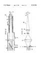
- FIG. 2is a schematic illustration of a laser delivery system for use with the apparatus and system of FIG. 1;
- FIG. 3is a schematic illustration of an ophthalmic delivery system for use with the apparatus and system of FIG. 1;
- FIG. 4is a plan view of a mask usable with the apparatus and system of FIG. 1;
- FIG. 5is a plan view of another mask useable with the apparatus and system of FIG. 1;
- FIG. 6is a sectional view through a mask useable with the apparatus and system of FIG. 1;
- FIG. 7is a sectional view of another mask usable with the apparatus and system of FIG. 1;
- FIG. 8is a sectional view of yet another mask usable with the apparatus and system of FIG. 1;
- FIG. 9is a sectional view through the schematic eye of FIG. 1 during the surgical procedure according to the instant invention.
- FIG. 10is a sectional view through the schematic eye of FIGS. 1 and 9 following the surgical procedure according to the instant invention.
- FIG. 11is a sectional view perpendicular to a groove formed by photoablation according to the instant invention using the mask of FIG. 4;
- FIG. 12is a schematic view perpendicular to a V-shaped groove formed by photoablation according to the instant invention.
- the inventionwill be described as applied to a laser photoablation and method utilizing an argon-fluoride excimer laser which generates far-ultraviolet radiation at 193 nm (nanometers) at predetermined pulse energy densities and repetition rates.
- Far-ultraviolet lightmay he produced by other lasers to be incorporated into this ophthalmic surgical system.
- the wavelengths of light applicableextend to 248 nm in spite of the less pure photodecomposition noted.
- the laser beamis thereafter directed through a mask formed from particular material and with one or more slit or circular openings to impinge upon an area of the cornea of an eye to form therein a groove of predetermined peripheral configuration and depth.
- the mask openingscan be of any convenient peripheral configuration; the masks may be formed of any appropriate material; a fiber-optic pipe and rod delivery system may be utilized without masks, and the apparatus and system may be utilized for procedures on other tissues and biological matter, such as dental caries, human skin, and the like.
- a photoablation laser surgery apparatus and systemutilizing a laser delivery system 22 and associated power supply and control system 24 by which a laser beam 26 is directed through openings 28 formed in a mask 30 and onto the cornea 32 of an eye 34, of either a human or an animal.
- Laser delivery system 22includes an argon-fluoride excimer laser such as one currently manufactured by Lamda Physik as their Model 201E. However, it is understood that other laser sources may be used to produce the effective ultraviolet light. Laser system 22 generates a laser beam 26 in the far-ultraviolet range of 193 nm (nanometers). Other ranges of ultraviolet wavelengths may be chosen. Power supply and control 24 is conventionally available and is interconnected to laser system 22 so that the output thereof is pulsed at pulse energy densities of greater than 420 mj per cm 2 (milijoules per square centimeter) at a repetition rate up to 25 pulses per second.
- FIG. 2illustrates a laser delivery system 50 wherein an ultra-violet laser beam 52 is directed through lens 54 and then through a passage 56 and opening 58.
- An appropriate opening 60is provided to passage 56 for infusion of nitrogen or other similar gases.
- Another opening 62is provided for passage 56 to provide a high vacuum therefor.
- an ophthalmic delivery system 80for generating and delivering a laser generated ultraviolet laser beam 82 through a variable slit 84 to and through a lens 86, through an aperture 88, through another lens 90, and onto an area, such as an eye 92, upon which a surgical procedure is to be performed.
- Mask 30(FIGS. 1 and 4) is formed from aluminum, or other appropriate material, and includes a number of slits 100 formed therethrough.
- the slits 100range in width from 150 to 800 microns. While four slits have been shown for mask 30, it should be understood that a lesser or greater number of slits can be provided for mask 30 and that the widths as well as the slit configuration can be appropriately selected.
- An alternate mask 110shown in FIG. 5, is formed with seven holes 112 drilled or otherwise formed therethrough. Holes 112 range in diameter from 100 microns to 750 microns. It should be understood that openings of any desired configuration (crescents, concentric rings, etc.) may be formed through masks 30 and 110.
- the maskmay also be formed to provide a graded intensity center to edge or edge to center.
- the maskmay be clad or covered with plastic or other polymers to prevent heating of the mask.
- the organic materialwill prevent ultra-violet light from striking the mask and heating it directly.
- the claddingprevents heating by being ablated by the ultraviolet light which is being shielded from the eye.
- FIG. 6there is shown a mask 120 with an opening 122 and having a surface of 2000 ⁇ chrome formed onto a base 124 of poly methyl methacrylate to reflect the ultra-violet light and to prevent heating.
- the maskis stabilized by a vacuum seal.
- FIG. 7there is a mask 130 with an opening 132.
- FIG. 8shows still another alternate mask 140 with an opening 142.
- Mask 140includes one or more metal cooling vanes 144 separated by an air space 146 from, but otherwise carried by or supported with respect to, a base 148 of stainless steel; all being stabilized by a vacuum seal.
- masks 120, 130, and 140have been shown with single openings 122, 132, 142, respectively, it should by understood that any suitable number of openings may be formed in the masks, and that such openings may be formed with any appropriate configuration and width.
- laser apparatus 20is positioned with respect to the area of tissue, biological matter, or the like upon which the surgical procedure is to be performed.
- laser 20is disposed with respect to cornea 32 of an eye 34 so that laser beam 26 will be directed towards mask 30 and then upon cornea 32.
- the output of laser 20is delivered in a series of pulses under control of laser delivery system 22 and laser power supply and control system 24. For each micron depth of corneal tissue to be ablated, one joule per square centimeter was applied. Thus in forming a 200 micron deep groove, for example, 200 joules per cm 2 would be required. This was delivered in a series of pulses varying in intensity between 100 and 200 mj per square centimeter depending upon the area of the final focus of laser apparatus 20.
- the laser pulse rate for apparatus 20was between 1 and 25 Hertz and the pulses were delivered until sufficient total energy achieved the desired depth of cut.
- the maximum exposure time for the complete section of the cornea as describedrequired 100 second (700 mj per cm 2 ). More rapid pulse rates create tissue heating distortion from gas pressure backup in the irradiated area. Higher energy densities in the irradiated area produce unwanted shock effects.
- eye 34is shown during the above described procedure and illustrates the bond breaking occurring at 150 in the epithelium 152 and stromal collagen 154.
- the ablated groove 160is shown.
- a groove 200(FIG. 11) can be formed with parallel walls 202 and a square bottom 204.
- a V-shaped groove 210may be formed by apparatus 20 and the described procedure by directing laser beam 28 so that it strikes cornea 32 obliquely. By doing so, the energy distribution across a slit or other opening formed through mask 30 will cause the tissue to ablate more rapidly at one edge.
- the described apparatus 20 and methodcauses a specific photo-chemical reaction and results in the ablation of corneal or other tissues without thermal damage to the adjacent remaining structures.
- the methodallows incisions of controlled depth and shape. Defined volumes of tissue can be removed by masking to control the area ablating the tissue to a predetermined depth.
- the corneal epitheliumshows an extreme sensitivity to the 193 nm light emitted by the argon-fluoride excimer laser of apparatus 20.
- the tissueis broken into smaller volatile fragments by direct photo-chemical interaction without heating the remaining adjacent tissues.
- Ultraviolet light at 193 nmis highly energetic, each photon having 6.4 electron volts. The high energy of each photon directly breaks intramolecular bonds.
- Apparatus 20 and the described methodwill produce an incision resembling that formed by a surgical cut. There will be a parallel between the gross corneal appearance and the mask, and no distortion of the stromal lamellae or epithelial edge. The groove walls will be parallel along their entire length and have a squared bottom.
- the ablative photodecomposition accomplished by the described apparatus and methodwill provide grooves of a precisely determined shaped and to a precisely determined depth. This has the same clinical indication as lamellar keratectomy, since precise excision of the corneal tissue can be accomplished.
- a controlled penetrating corneal incisioncan, in principal, be done for corneal transplantation.
- Radial incisions as well as concentric rings and crescentscan be accomplished with the described apparatus and method.
- the laser light of the described method and apparatuscan be applied to a circular mask of graded intensity center to edge. This would take away more tissue either centrally or peripherally depending on the distribution of light. The net effect would be either to steepen or flatten the cornea.
- the ability to make controlled radial incisions, or to selectively shape the corneal surfaceallows modification of the refractive status of the eye.
- apparatus 20can be provided with a fiber-optic pipe or rod delivery system to allow placement of UV laser light to intraocular structures. This would allow (a) controlled filtering operation for glaucoma to be done subconjunctivally or via the anterior chamber; and (b) a "phakoemulsification" to be done with pulsed ultraviolet light rather than a vibrating titanium rod; (c) placement of the unit in the eye to section vitreous membranes as an alternative to rotating or oscillating knives.
- such a fiber-optic rod delivery systemcan be used in the treatment of dental caries by directing the light to the affected area or can be used in the removal of skin lesions
Landscapes
- Health & Medical Sciences (AREA)
- Ophthalmology & Optometry (AREA)
- Heart & Thoracic Surgery (AREA)
- Vascular Medicine (AREA)
- Optics & Photonics (AREA)
- Surgery (AREA)
- Engineering & Computer Science (AREA)
- Biomedical Technology (AREA)
- Physics & Mathematics (AREA)
- Nuclear Medicine, Radiotherapy & Molecular Imaging (AREA)
- Life Sciences & Earth Sciences (AREA)
- Animal Behavior & Ethology (AREA)
- General Health & Medical Sciences (AREA)
- Public Health (AREA)
- Veterinary Medicine (AREA)
- Laser Surgery Devices (AREA)
Abstract
Description
Claims (23)
Priority Applications (1)
| Application Number | Priority Date | Filing Date | Title |
|---|---|---|---|
| US08/474,243US5711762A (en) | 1983-12-15 | 1995-06-07 | Laser surgery apparatus and method |
Applications Claiming Priority (7)
| Application Number | Priority Date | Filing Date | Title |
|---|---|---|---|
| US56180483A | 1983-12-15 | 1983-12-15 | |
| US85921286A | 1986-05-02 | 1986-05-02 | |
| US07109812US5108388B1 (en) | 1983-12-15 | 1987-10-16 | Laser surgery method |
| US67354191A | 1991-03-18 | 1991-03-18 | |
| US89384192A | 1992-06-04 | 1992-06-04 | |
| US34120794A | 1994-12-05 | 1994-12-05 | |
| US08/474,243US5711762A (en) | 1983-12-15 | 1995-06-07 | Laser surgery apparatus and method |
Related Parent Applications (1)
| Application Number | Title | Priority Date | Filing Date |
|---|---|---|---|
| US34120794ADivision | 1983-12-15 | 1994-12-05 |
Publications (1)
| Publication Number | Publication Date |
|---|---|
| US5711762Atrue US5711762A (en) | 1998-01-27 |
Family
ID=46251519
Family Applications (2)
| Application Number | Title | Priority Date | Filing Date |
|---|---|---|---|
| US08/474,243Expired - LifetimeUS5711762A (en) | 1983-12-15 | 1995-06-07 | Laser surgery apparatus and method |
| US08/480,243Expired - LifetimeUS5735843A (en) | 1983-12-15 | 1995-06-07 | Laser surgery apparatus and method |
Family Applications After (1)
| Application Number | Title | Priority Date | Filing Date |
|---|---|---|---|
| US08/480,243Expired - LifetimeUS5735843A (en) | 1983-12-15 | 1995-06-07 | Laser surgery apparatus and method |
Country Status (1)
| Country | Link |
|---|---|
| US (2) | US5711762A (en) |
Cited By (32)
| Publication number | Priority date | Publication date | Assignee | Title |
|---|---|---|---|---|
| US5904678A (en)* | 1995-06-19 | 1999-05-18 | Lasersight Technologies, Inc. | Multizone, multipass photorefractive keratectomy |
| US5997529A (en) | 1996-10-28 | 1999-12-07 | Lasersight Technologies, Inc. | Compound astigmatic myopia or hyperopia correction by laser ablation |
| US6007202A (en) | 1997-10-23 | 1999-12-28 | Lasersight Technologies, Inc. | Eye illumination system and method |
| US6010497A (en)* | 1998-01-07 | 2000-01-04 | Lasersight Technologies, Inc. | Method and apparatus for controlling scanning of an ablating laser beam |
| US6132424A (en) | 1998-03-13 | 2000-10-17 | Lasersight Technologies Inc. | Smooth and uniform laser ablation apparatus and method |
| US6210169B1 (en) | 1997-01-31 | 2001-04-03 | Lasersight Technologies, Inc. | Device and method for simulating ophthalmic surgery |
| US6270221B1 (en) | 1998-08-19 | 2001-08-07 | Alcon Universal Ltd. | Apparatus and method for measuring vision defects of a human eye |
| US6271915B1 (en) | 1996-11-25 | 2001-08-07 | Autonomous Technologies Corporation | Objective measurement and correction of optical systems using wavefront analysis |
| US6409718B1 (en) | 1998-02-03 | 2002-06-25 | Lasersight Technologies, Inc. | Device and method for correcting astigmatism by laser ablation |
| US6450641B2 (en) | 1992-06-02 | 2002-09-17 | Lasersight Technologies, Inc. | Method of corneal analysis using a checkered placido apparatus |
| DE19943723C2 (en)* | 1999-09-03 | 2002-11-07 | Zeiss Carl Jena Gmbh | Device for irradiating the eye |
| US6478792B1 (en) | 1999-09-03 | 2002-11-12 | Carl Zeiss Jena Gmbh | Method and apparatus for illumination of the eye |
| US6497701B2 (en) | 1999-04-30 | 2002-12-24 | Visx, Incorporated | Method and system for ablating surfaces with partially overlapping craters having consistent curvature |
| US6497483B2 (en) | 2000-05-08 | 2002-12-24 | Alcon, Inc. | Apparatus and method for objective measurement of optical systems using wavefront analysis |
| US20030018347A1 (en)* | 2001-07-23 | 2003-01-23 | Ioannis Pallikaris | Device for separating the epithelium layer from the surface of the cornea of an eye |
| US6530916B1 (en) | 1999-11-15 | 2003-03-11 | Visx, Incorporated | Uniform large area ablation system and method |
| US6578963B2 (en) | 2000-04-19 | 2003-06-17 | Alcon Universal Ltd. | Wavefront sensor for objective measurement of an optical system and associated methods |
| US6626897B2 (en) | 1994-04-25 | 2003-09-30 | Alcon, Inc. | Method of redirecting an ablating laser beam |
| US6716210B2 (en) | 1992-12-03 | 2004-04-06 | Lasersight Technologies, Inc. | Refractive surgical laser apparatus and method |
| US20040130677A1 (en)* | 1998-08-19 | 2004-07-08 | Alcon, Inc. | Apparatus and method for measuring vision defects of a human eye |
| US20040220599A1 (en)* | 2001-07-23 | 2004-11-04 | Fos Holding S.A. | Device for separating the epithelium layer from the surface of the cornea of an eye |
| US20040260320A1 (en)* | 2002-12-10 | 2004-12-23 | Lisk James R. | Disposable separator for separating the epithelium layer from the cornea of an eye |
| US20040260321A1 (en)* | 2002-12-19 | 2004-12-23 | Ming-Kok Tai | Apparatus and method for separating the epithelium layer from the cornea of an eye without corneal pre-applanation |
| US20050124983A1 (en)* | 1996-11-25 | 2005-06-09 | Frey Rudolph W. | Method for determining and correcting vision |
| DE19943735B4 (en)* | 1999-09-03 | 2007-04-26 | Carl Zeiss Meditec Ag | Device for irradiating the eye |
| US7252662B2 (en) | 2004-11-02 | 2007-08-07 | Lenticular Research Group Llc | Apparatus and processes for preventing or delaying one or more symptoms of presbyopia |
| US20070265650A1 (en)* | 2001-07-23 | 2007-11-15 | Ioannis Pallikaris | Device for separating the epithelial layer from the surface of the cornea of an eye |
| US20080161781A1 (en)* | 2005-02-19 | 2008-07-03 | Mcardle George J | Apparatus and Processes For Preventing or Delaying Onset or Progression of Age-Related Cataract |
| US20110112519A1 (en)* | 2008-06-20 | 2011-05-12 | Christof Donitzky | Apparatus for cutting a tissue part with focused laser radiation |
| US20140098342A1 (en)* | 2011-11-04 | 2014-04-10 | The General Hospital Corporation | System and method for corneal irradiation |
| KR101632075B1 (en)* | 2016-03-21 | 2016-06-20 | 주식회사 제이티에스인더스트리 | ND-YAG laser system For skin treatment using Stable resonator and Unstable resonator |
| US10772763B2 (en)* | 2015-08-31 | 2020-09-15 | Cesar C. Carriazo | Treatment apparatus for correcting a refractive error of an eye |
Families Citing this family (9)
| Publication number | Priority date | Publication date | Assignee | Title |
|---|---|---|---|---|
| USRE37504E1 (en) | 1992-12-03 | 2002-01-08 | Lasersight Technologies, Inc. | Ophthalmic surgery method using non-contact scanning laser |
| EP1164960A1 (en)* | 1999-01-13 | 2002-01-02 | LaserSight Technologies, Inc. | Profiling calibration plate |
| MXPA01013363A (en) | 2000-04-25 | 2002-07-02 | Alcon Universal Ltd | Laser ablation zone restriction system and method. |
| US6464692B1 (en)* | 2000-06-21 | 2002-10-15 | Luis Antonio Ruiz | Controllable electro-optical patternable mask, system with said mask and method of using the same |
| US6436093B1 (en)* | 2000-06-21 | 2002-08-20 | Luis Antonio Ruiz | Controllable liquid crystal matrix mask particularly suited for performing ophthamological surgery, a laser system with said mask and a method of using the same |
| ATE497807T1 (en)* | 2003-03-27 | 2011-02-15 | Gen Hospital Corp | DEVICE FOR DERMATOLOGICAL TREATMENT AND FRACTIONAL SURFACE RENEWAL OF THE SKIN |
| AU2016342057A1 (en) | 2015-10-23 | 2018-03-01 | The Trustees Of Columbia University In The City Of New York | Laser induced collagen crosslinking in tissue |
| US11497403B2 (en) | 2016-06-10 | 2022-11-15 | The Trustees Of Columbia University In The City Of New York | Devices, methods, and systems for detection of collagen tissue features |
| US11666481B1 (en) | 2017-12-01 | 2023-06-06 | The Trustees Of Columbia University In The City Of New York | Diagnosis and treatment of collagen-containing tissues |
Citations (19)
| Publication number | Priority date | Publication date | Assignee | Title |
|---|---|---|---|---|
| US3330182A (en)* | 1965-10-01 | 1967-07-11 | Gerber Scientific Instr Co | Device for exposing discrete portions of a photosensitive surface to a variable intensity light beam |
| US3710798A (en)* | 1971-08-30 | 1973-01-16 | American Optical Corp | Laser system for microsurgery |
| US3769963A (en)* | 1972-03-31 | 1973-11-06 | L Goldman | Instrument for performing laser micro-surgery and diagnostic transillumination of living human tissue |
| US3828788A (en)* | 1972-08-31 | 1974-08-13 | M Krasnov | Laser opthalmoscope |
| US3982541A (en)* | 1974-07-29 | 1976-09-28 | Esperance Jr Francis A L | Eye surgical instrument |
| US4170997A (en)* | 1977-08-26 | 1979-10-16 | Hughes Aircraft Company | Medical laser instrument for transmitting infrared laser energy to a selected part of the body |
| US4301118A (en)* | 1980-03-06 | 1981-11-17 | Spectrum Medical Industries, Inc. | Protein concentrator |
| US4309998A (en)* | 1978-06-08 | 1982-01-12 | Aron Rosa Daniele S | Process and apparatus for ophthalmic surgery |
| US4409979A (en)* | 1979-11-28 | 1983-10-18 | Lasag Ag | Device for observing and treating the eye using a laser |
| US4461294A (en)* | 1982-01-20 | 1984-07-24 | Baron Neville A | Apparatus and process for recurving the cornea of an eye |
| US4485499A (en)* | 1982-09-02 | 1984-12-04 | Castleman Lawrence D | Intraocular posterior chamber lens |
| US4538608A (en)* | 1984-03-23 | 1985-09-03 | Esperance Jr Francis A L | Method and apparatus for removing cataractous lens tissue by laser radiation |
| US4724372A (en)* | 1985-09-19 | 1988-02-09 | Tokyo Keiki Company Ltd. | Speed control apparatus of hydraulic actuator |
| US4729372A (en)* | 1983-11-17 | 1988-03-08 | Lri L.P. | Apparatus for performing ophthalmic laser surgery |
| US4732148A (en)* | 1983-11-17 | 1988-03-22 | Lri L.P. | Method for performing ophthalmic laser surgery |
| US4744360A (en)* | 1986-12-18 | 1988-05-17 | Bath Patricia E | Apparatus for ablating and removing cataract lenses |
| US4784135A (en)* | 1982-12-09 | 1988-11-15 | International Business Machines Corporation | Far ultraviolet surgical and dental procedures |
| US4825865A (en)* | 1987-05-01 | 1989-05-02 | Jerry Zelman | Apparatus and method for extracting cataract tissue |
| US4846172A (en)* | 1987-05-26 | 1989-07-11 | Berlin Michael S | Laser-delivery eye-treatment method |
Family Cites Families (4)
| Publication number | Priority date | Publication date | Assignee | Title |
|---|---|---|---|---|
| US4266548A (en)* | 1978-12-18 | 1981-05-12 | Davi S K | Apparatus for and method of utilizing energy to excise pathological tissue |
| EP0111060B1 (en)* | 1982-12-09 | 1987-08-19 | International Business Machines Corporation | Ablative photodecomposition of organic biological material |
| FR2576780B1 (en)* | 1985-02-04 | 1991-06-14 | Azema Alain | APPARATUS FOR CHANGING THE CURVATURE OF THE EYE CORNEA OVER THE WHOLE PUPILLARY SURFACE BY PHOTOCHEMICAL ABLATION OF THE SAME |
| US4769963A (en)* | 1987-07-09 | 1988-09-13 | Structural Panels, Inc. | Bonded panel interlock device |
- 1995
- 1995-06-07USUS08/474,243patent/US5711762A/ennot_activeExpired - Lifetime
- 1995-06-07USUS08/480,243patent/US5735843A/ennot_activeExpired - Lifetime
Patent Citations (19)
| Publication number | Priority date | Publication date | Assignee | Title |
|---|---|---|---|---|
| US3330182A (en)* | 1965-10-01 | 1967-07-11 | Gerber Scientific Instr Co | Device for exposing discrete portions of a photosensitive surface to a variable intensity light beam |
| US3710798A (en)* | 1971-08-30 | 1973-01-16 | American Optical Corp | Laser system for microsurgery |
| US3769963A (en)* | 1972-03-31 | 1973-11-06 | L Goldman | Instrument for performing laser micro-surgery and diagnostic transillumination of living human tissue |
| US3828788A (en)* | 1972-08-31 | 1974-08-13 | M Krasnov | Laser opthalmoscope |
| US3982541A (en)* | 1974-07-29 | 1976-09-28 | Esperance Jr Francis A L | Eye surgical instrument |
| US4170997A (en)* | 1977-08-26 | 1979-10-16 | Hughes Aircraft Company | Medical laser instrument for transmitting infrared laser energy to a selected part of the body |
| US4309998A (en)* | 1978-06-08 | 1982-01-12 | Aron Rosa Daniele S | Process and apparatus for ophthalmic surgery |
| US4409979A (en)* | 1979-11-28 | 1983-10-18 | Lasag Ag | Device for observing and treating the eye using a laser |
| US4301118A (en)* | 1980-03-06 | 1981-11-17 | Spectrum Medical Industries, Inc. | Protein concentrator |
| US4461294A (en)* | 1982-01-20 | 1984-07-24 | Baron Neville A | Apparatus and process for recurving the cornea of an eye |
| US4485499A (en)* | 1982-09-02 | 1984-12-04 | Castleman Lawrence D | Intraocular posterior chamber lens |
| US4784135A (en)* | 1982-12-09 | 1988-11-15 | International Business Machines Corporation | Far ultraviolet surgical and dental procedures |
| US4729372A (en)* | 1983-11-17 | 1988-03-08 | Lri L.P. | Apparatus for performing ophthalmic laser surgery |
| US4732148A (en)* | 1983-11-17 | 1988-03-22 | Lri L.P. | Method for performing ophthalmic laser surgery |
| US4538608A (en)* | 1984-03-23 | 1985-09-03 | Esperance Jr Francis A L | Method and apparatus for removing cataractous lens tissue by laser radiation |
| US4724372A (en)* | 1985-09-19 | 1988-02-09 | Tokyo Keiki Company Ltd. | Speed control apparatus of hydraulic actuator |
| US4744360A (en)* | 1986-12-18 | 1988-05-17 | Bath Patricia E | Apparatus for ablating and removing cataract lenses |
| US4825865A (en)* | 1987-05-01 | 1989-05-02 | Jerry Zelman | Apparatus and method for extracting cataract tissue |
| US4846172A (en)* | 1987-05-26 | 1989-07-11 | Berlin Michael S | Laser-delivery eye-treatment method |
Non-Patent Citations (30)
| Title |
|---|
| "An Extreem Sensitivity in the Corneal Epithelusa to For WARF Excime Laser Pulses" Toboda et al Aerospace Medical Assoc. 1981 Meeting San Antonio TX (Taboda et al (1981)). |
| "Excimer Laser Surgery of the Cornea" by Trokel et al.; Am. J. Opthalmology; vol. 96; No. 6; Dec. 1983; pp. 710-715. |
| "Response to the Corneal Epithelium to KrF Excimer Laser Pulses" by Tabouda et al; Health Physics vol. 40, May 1981 pp. 677-683. |
| An Extreem Sensitivity in the Corneal Epithelusa to For WARF Excime Laser Pulses Toboda et al Aerospace Medical Assoc. 1981 Meeting San Antonio TX (Taboda et al (1981)).* |
| Deposition of Alain Azema; Civil Action no. 95 524 SLR; United States District Court for the District of Delaware; Sep. 17, 1996.* |
| Deposition of Alain Azema; Civil Action no. 95-524-SLR; United States District Court for the District of Delaware; Sep. 17, 1996. |
| Excimer Laser Surgery of the Cornea by Trokel et al.; Am. J. Opthalmology; vol. 96; No. 6; Dec. 1983; pp. 710 715.* |
| Facsimile letter dated Feb. 8, 1995 from Howard L. Milhench, attorney for VISX Corporation, to the European patent office containing applicant s preliminary response to (1) an opposition by Firma Carl Zeiss and (2) an opposition by Summit Technology, Inc. to European patent application No. 87306826.6 2212/0257836.* |
| Facsimile letter dated Feb. 8, 1995 from Howard L. Milhench, attorney for VISX Corporation, to the European patent office containing applicant's preliminary response to (1) an opposition by Firma Carl Zeiss and (2) an opposition by Summit Technology, Inc. to European patent application No. 87306826.6-2212/0257836. |
| Facsimile letter dated Jun. 2, 1994 from Howard L. Wibench, attorney for VISX Corporation, to the European patent office containing VISX s preliminary response to (1) an opposition by Firma Carl Zeiss and (2) an opposition by Summit Technology, Inc. to European patent application No. 87310283.4 0274205.* |
| Facsimile letter dated Jun. 2, 1994 from Howard L. Wibench, attorney for VISX Corporation, to the European patent office containing VISX's preliminary response to (1) an opposition by Firma Carl Zeiss and (2) an opposition by Summit Technology, Inc. to European patent application No. 87310283.4-0274205. |
| Facsimile letter dated Jun. 7, 1994 from Howard L. Milhench, attorney for VISX Corporation, to the European patent office containing applicant s preliminary response to an opposition by Summit Technology, Inc. to European patent application No. 86307420.9 2305/021842.* |
| Facsimile letter dated Jun. 7, 1994 from Howard L. Milhench, attorney for VISX Corporation, to the European patent office containing applicant's preliminary response to an opposition by Summit Technology, Inc. to European patent application No. 86307420.9-2305/021842. |
| Facsimile message dated Dec. 23, 1991 from Howard L. Milhench, attorney for VISX Corporation, to the European patent ofice containing VISX s observations regarding (1) an opposition by Synthelabo, Paris (FR) and (2) an opposition by Zeiss, Oberkochen (DE) to European patent application No. 896304315.4 2305.* |
| Facsimile message dated Dec. 23, 1991 from Howard L. Milhench, attorney for VISX Corporation, to the European patent ofice containing VISX's observations regarding (1) an opposition by Synthelabo, Paris (FR) and (2) an opposition by Zeiss, Oberkochen (DE) to European patent application No. 896304315.4-2305. |
| Form EPO 2042 dated Dec. 29, 1995 having reference No. J.17848 in European patent application No. 86307420.9 2302/0218427.* |
| Form EPO 2042 dated Dec. 29, 1995 having reference No. J.17848 in European patent application No. 86307420.9-2302/0218427. |
| Letter dated Sep. 22, 1994 from Howard L. Milhench, attorney for VISX Corporation, to the European patent office containing applicant s preliminary response to (1) an opposition by Firma Carl Zeiss and (2) an opposition by Summit Technology, Inc. to European patent application No. 87310283.4 0274205.* |
| Letter dated Sep. 22, 1994 from Howard L. Milhench, attorney for VISX Corporation, to the European patent office containing applicant's preliminary response to (1) an opposition by Firma Carl Zeiss and (2) an opposition by Summit Technology, Inc. to European patent application No. 87310283.4-0274205. |
| Paper in European patent application Nos. 86307420.9 2305/0218427 and 87306826.6 2302/0257836 titled Affidavit of Stephen L. Trokel Sworn on Dec. 5, 1995.* |
| Paper in European patent application Nos. 86307420.9-2305/0218427 and 87306826.6-2302/0257836 titled "Affidavit of Stephen L. Trokel" Sworn on Dec. 5, 1995. |
| Rebuttal Expert of Dr. Michael S. Feld Re: Validity; Civil Action No. 95 524 SLR; United States District Court for the District of Delaware; Dec. 30, 1996.* |
| Rebuttal Expert of Dr. Michael S. Feld Re: Validity; Civil Action No. 95-524-SLR; United States District Court for the District of Delaware; Dec. 30, 1996. |
| Rebuttal Expert Report of Dr. Jack Feinberg Re: Validity; Civil Action No. 95 524 SLR; United States District Court for the District of Delaware; Dec. 23, 1996.* |
| Rebuttal Expert Report of Dr. Jack Feinberg Re: Validity; Civil Action No. 95-524-SLR; United States District Court for the District of Delaware; Dec. 23, 1996. |
| Rebuttal Expert Report of Roger F. Steinert, M.D. Re: Validity; Civil Action No. 95 524 SLR; United States District Court for the District of Delaware; Dec. 30, 1996.* |
| Rebuttal Expert Report of Roger F. Steinert, M.D. Re: Validity; Civil Action No. 95-524-SLR; United States District Court for the District of Delaware; Dec. 30, 1996. |
| Report of James H. Brannon Pursuant to Federal rule of Civil Procedure 26; Civil Action No. 95 524 SLR; United States District Court for the District of Delaware, Dec. 9, 1996.* |
| Report of James H. Brannon Pursuant to Federal rule of Civil Procedure 26; Civil Action No. 95-524 SLR; United States District Court for the District of Delaware, Dec. 9, 1996. |
| Response to the Corneal Epithelium to KrF Excimer Laser Pulses by Tabouda et al; Health Physics vol. 40, May 1981 pp. 677 683.* |
Cited By (47)
| Publication number | Priority date | Publication date | Assignee | Title |
|---|---|---|---|---|
| US6450641B2 (en) | 1992-06-02 | 2002-09-17 | Lasersight Technologies, Inc. | Method of corneal analysis using a checkered placido apparatus |
| US6716210B2 (en) | 1992-12-03 | 2004-04-06 | Lasersight Technologies, Inc. | Refractive surgical laser apparatus and method |
| US6626896B2 (en) | 1994-04-25 | 2003-09-30 | Alcon, Inc. | Method of correcting vision |
| US6626898B2 (en) | 1994-04-25 | 2003-09-30 | Alcon, Inc. | Flying spot laser ablation method |
| US6626897B2 (en) | 1994-04-25 | 2003-09-30 | Alcon, Inc. | Method of redirecting an ablating laser beam |
| US6626894B2 (en) | 1994-04-25 | 2003-09-30 | Alcon, Inc. | Method of ablating a moving eye |
| US6626895B2 (en) | 1994-04-25 | 2003-09-30 | Alcon, Inc. | Laser beam delivery system |
| US5904678A (en)* | 1995-06-19 | 1999-05-18 | Lasersight Technologies, Inc. | Multizone, multipass photorefractive keratectomy |
| US5997529A (en) | 1996-10-28 | 1999-12-07 | Lasersight Technologies, Inc. | Compound astigmatic myopia or hyperopia correction by laser ablation |
| US20050124983A1 (en)* | 1996-11-25 | 2005-06-09 | Frey Rudolph W. | Method for determining and correcting vision |
| US6271914B1 (en) | 1996-11-25 | 2001-08-07 | Autonomous Technologies Corporation | Objective measurement and correction of optical systems using wavefront analysis |
| US6271915B1 (en) | 1996-11-25 | 2001-08-07 | Autonomous Technologies Corporation | Objective measurement and correction of optical systems using wavefront analysis |
| US6210169B1 (en) | 1997-01-31 | 2001-04-03 | Lasersight Technologies, Inc. | Device and method for simulating ophthalmic surgery |
| US6334683B2 (en) | 1997-10-23 | 2002-01-01 | Lasersight Technologies, Inc. | Eye illumination system and method |
| US6193373B1 (en) | 1997-10-23 | 2001-02-27 | Lasersight Technologies, Inc. | Eye illumination system and method |
| US6007202A (en) | 1997-10-23 | 1999-12-28 | Lasersight Technologies, Inc. | Eye illumination system and method |
| US6010497A (en)* | 1998-01-07 | 2000-01-04 | Lasersight Technologies, Inc. | Method and apparatus for controlling scanning of an ablating laser beam |
| US6409718B1 (en) | 1998-02-03 | 2002-06-25 | Lasersight Technologies, Inc. | Device and method for correcting astigmatism by laser ablation |
| US6132424A (en) | 1998-03-13 | 2000-10-17 | Lasersight Technologies Inc. | Smooth and uniform laser ablation apparatus and method |
| US20040130677A1 (en)* | 1998-08-19 | 2004-07-08 | Alcon, Inc. | Apparatus and method for measuring vision defects of a human eye |
| US6270221B1 (en) | 1998-08-19 | 2001-08-07 | Alcon Universal Ltd. | Apparatus and method for measuring vision defects of a human eye |
| US6497701B2 (en) | 1999-04-30 | 2002-12-24 | Visx, Incorporated | Method and system for ablating surfaces with partially overlapping craters having consistent curvature |
| DE19943723C2 (en)* | 1999-09-03 | 2002-11-07 | Zeiss Carl Jena Gmbh | Device for irradiating the eye |
| US6478792B1 (en) | 1999-09-03 | 2002-11-12 | Carl Zeiss Jena Gmbh | Method and apparatus for illumination of the eye |
| DE19943735B4 (en)* | 1999-09-03 | 2007-04-26 | Carl Zeiss Meditec Ag | Device for irradiating the eye |
| US6530916B1 (en) | 1999-11-15 | 2003-03-11 | Visx, Incorporated | Uniform large area ablation system and method |
| US6578963B2 (en) | 2000-04-19 | 2003-06-17 | Alcon Universal Ltd. | Wavefront sensor for objective measurement of an optical system and associated methods |
| US6497483B2 (en) | 2000-05-08 | 2002-12-24 | Alcon, Inc. | Apparatus and method for objective measurement of optical systems using wavefront analysis |
| US7156859B2 (en) | 2001-07-23 | 2007-01-02 | Fos Holding S.A. | Device for separating the epithelium layer from the surface of the cornea of an eye |
| US7708750B2 (en) | 2001-07-23 | 2010-05-04 | Fos Holdings S.A. | Device for separating the epithelium layer from the surface of the cornea of an eye |
| US20040220599A1 (en)* | 2001-07-23 | 2004-11-04 | Fos Holding S.A. | Device for separating the epithelium layer from the surface of the cornea of an eye |
| US20070265650A1 (en)* | 2001-07-23 | 2007-11-15 | Ioannis Pallikaris | Device for separating the epithelial layer from the surface of the cornea of an eye |
| US20040167555A1 (en)* | 2001-07-23 | 2004-08-26 | Fos Holding S.A. | Device for separating the epithelium layer from the surface of the cornea of an eye |
| US20050288696A1 (en)* | 2001-07-23 | 2005-12-29 | Pallikaris Ioannis G | Device for separating the epithelial layer from the surface of the cornea of an eye |
| US7004953B2 (en) | 2001-07-23 | 2006-02-28 | Fos Holding S.A. | Device for separating the epithelium layer from the surface of the cornea of an eye |
| US20030018347A1 (en)* | 2001-07-23 | 2003-01-23 | Ioannis Pallikaris | Device for separating the epithelium layer from the surface of the cornea of an eye |
| US20030018348A1 (en)* | 2001-07-23 | 2003-01-23 | Ioannis Pallikaris | Device for separating the epithelium layer from the surface of the cornea of an eye |
| US20040260320A1 (en)* | 2002-12-10 | 2004-12-23 | Lisk James R. | Disposable separator for separating the epithelium layer from the cornea of an eye |
| US20040260321A1 (en)* | 2002-12-19 | 2004-12-23 | Ming-Kok Tai | Apparatus and method for separating the epithelium layer from the cornea of an eye without corneal pre-applanation |
| US7252662B2 (en) | 2004-11-02 | 2007-08-07 | Lenticular Research Group Llc | Apparatus and processes for preventing or delaying one or more symptoms of presbyopia |
| US20070299430A1 (en)* | 2004-11-02 | 2007-12-27 | Lenticular Research Group Llc | Apparatus and processes for preventing or delaying one or more symptoms of presbyopia |
| US20080161781A1 (en)* | 2005-02-19 | 2008-07-03 | Mcardle George J | Apparatus and Processes For Preventing or Delaying Onset or Progression of Age-Related Cataract |
| US9649224B2 (en) | 2005-02-19 | 2017-05-16 | Lenticular Research Group Llc | Apparatus and processes for preventing or delaying onset or progression of age-related cataract |
| US20110112519A1 (en)* | 2008-06-20 | 2011-05-12 | Christof Donitzky | Apparatus for cutting a tissue part with focused laser radiation |
| US20140098342A1 (en)* | 2011-11-04 | 2014-04-10 | The General Hospital Corporation | System and method for corneal irradiation |
| US10772763B2 (en)* | 2015-08-31 | 2020-09-15 | Cesar C. Carriazo | Treatment apparatus for correcting a refractive error of an eye |
| KR101632075B1 (en)* | 2016-03-21 | 2016-06-20 | 주식회사 제이티에스인더스트리 | ND-YAG laser system For skin treatment using Stable resonator and Unstable resonator |
Also Published As
| Publication number | Publication date |
|---|---|
| US5735843A (en) | 1998-04-07 |
Similar Documents
| Publication | Publication Date | Title |
|---|---|---|
| US5711762A (en) | Laser surgery apparatus and method | |
| US5108388A (en) | Laser surgery method | |
| Trokel et al. | Excimer laser surgery of the cornea | |
| US4907586A (en) | Method for reshaping the eye | |
| US6059772A (en) | Apparatus and method for treating glaucoma using a gonioscopic laser trabecular ablation procedure | |
| Puliafito et al. | Quantitative and ultrastructural studies of excimer laser ablation of the cornea at 193 and 248 nanometers | |
| US5613965A (en) | Corneal reprofiling using an annular beam of ablative radiation | |
| Trokel | Evolution of excimer laser corneal surgery | |
| Fankhauser et al. | Clinical studies on the efficiency of high power laser radiation upon some structures of the anterior segment of the eye: first experiences of the treatment of some pathological conditions of the anterior segment of the human eye by means of a Q-switched laser system | |
| US6210399B1 (en) | Noncontact laser microsurgical method | |
| US4718418A (en) | Apparatus for ophthalmological surgery | |
| US5423801A (en) | Laser corneal surgery | |
| EP1389967B1 (en) | Apparatus for treatment of presbyopia and other eye disorders using fiber-coupled-lasers | |
| EP0151869B1 (en) | Apparatus for ophthalmological surgery | |
| L'Esperance et al. | Human excimer laser keratectomy: short-term histopathology | |
| KR101294326B1 (en) | Assembly and method for performing surgical laser treatments of the eye | |
| EP0207648B2 (en) | Apparatus for ophthalmological surgery | |
| Tsubota | Application of erbium: YAG laser in ocular ablation | |
| JPH07504337A (en) | Corneal sculpting using laser energy | |
| Hill et al. | Free-electron laser (FEL) ablation of ocular tissues | |
| US6063072A (en) | Methods and systems for correction of hyperopia and/or astigmatism using ablative radiation | |
| JPH0377553A (en) | Laser reshaping system using light-limiting mask | |
| Sliney et al. | Laser-tissue interactions | |
| Marshall | Lasers in ophthalmology: the basic principles | |
| Ren et al. | Laser refractive surgery: a review and current status |
Legal Events
| Date | Code | Title | Description |
|---|---|---|---|
| STCF | Information on status: patent grant | Free format text:PATENTED CASE | |
| CC | Certificate of correction | ||
| FEPP | Fee payment procedure | Free format text:PAT HLDR NO LONGER CLAIMS SMALL ENT STAT AS INDIV INVENTOR (ORIGINAL EVENT CODE: LSM1); ENTITY STATUS OF PATENT OWNER: LARGE ENTITY | |
| REFU | Refund | Free format text:REFUND - PAYMENT OF MAINTENANCE FEE, 4TH YR, SMALL ENTITY (ORIGINAL EVENT CODE: R283); ENTITY STATUS OF PATENT OWNER: LARGE ENTITY | |
| FPAY | Fee payment | Year of fee payment:4 | |
| FPAY | Fee payment | Year of fee payment:8 | |
| AS | Assignment | Owner name:BANK OF AMERICA, N.A., AS ADMINISTRATIVE AGENT, CA Free format text:INTELLECTUAL PROPERTY SECURITY AGREEMENT;ASSIGNOR:VISX, INCORPORATED;REEL/FRAME:016345/0640 Effective date:20050527 | |
| AS | Assignment | Owner name:VISX, INCORPORATED, CALIFORNIA Free format text:RELEASE OF SECURITY INTEREST AT REEL/FRAME NO. 16345/0640;ASSIGNOR:BANK OF AMERICA, N.A.;REEL/FRAME:019122/0101 Effective date:20070402 | |
| AS | Assignment | Owner name:BANK OF AMERICA, N.A., AS ADMINISTRATIVE AGENT,NOR Free format text:INTELLECTUAL PROPERTY SECURITY AGREEMENT;ASSIGNOR:VISX, INCORPORATED;REEL/FRAME:019501/0142 Effective date:20070402 Owner name:BANK OF AMERICA, N.A., AS ADMINISTRATIVE AGENT, NO Free format text:INTELLECTUAL PROPERTY SECURITY AGREEMENT;ASSIGNOR:VISX, INCORPORATED;REEL/FRAME:019501/0142 Effective date:20070402 | |
| AS | Assignment | Owner name:AMO MANUFACTURING USA, LLC, CALIFORNIA Free format text:CHANGE OF NAME;ASSIGNOR:VISX, INCORPORATED;REEL/FRAME:020299/0974 Effective date:20071231 | |
| AS | Assignment | Owner name:AMO MANUFACTURING USA, LLC; FORMERLY VISX, INCORPO Free format text:RELEASE BY SECURED PARTY;ASSIGNOR:BANK OF AMERICA, N.A. AS ADMINISTRATIVE AGENT;REEL/FRAME:022331/0698 Effective date:20090225 | |
| FPAY | Fee payment | Year of fee payment:12 |