US5711685A - Electrical connector having removable seal at cable entry end - Google Patents
Electrical connector having removable seal at cable entry endDownload PDFInfo
- Publication number
- US5711685A US5711685AUS08/590,148US59014896AUS5711685AUS 5711685 AUS5711685 AUS 5711685AUS 59014896 AUS59014896 AUS 59014896AUS 5711685 AUS5711685 AUS 5711685A
- Authority
- US
- United States
- Prior art keywords
- extending
- conductor
- seal member
- sheath
- seal
- Prior art date
- Legal status (The legal status is an assumption and is not a legal conclusion. Google has not performed a legal analysis and makes no representation as to the accuracy of the status listed.)
- Expired - Lifetime
Links
Images


Classifications
- H—ELECTRICITY
- H01—ELECTRIC ELEMENTS
- H01R—ELECTRICALLY-CONDUCTIVE CONNECTIONS; STRUCTURAL ASSOCIATIONS OF A PLURALITY OF MUTUALLY-INSULATED ELECTRICAL CONNECTING ELEMENTS; COUPLING DEVICES; CURRENT COLLECTORS
- H01R13/00—Details of coupling devices of the kinds covered by groups H01R12/70 or H01R24/00 - H01R33/00
- H01R13/46—Bases; Cases
- H01R13/52—Dustproof, splashproof, drip-proof, waterproof, or flameproof cases
- H01R13/5219—Sealing means between coupling parts, e.g. interfacial seal
- H01R13/5221—Sealing means between coupling parts, e.g. interfacial seal having cable sealing means
Definitions
- This inventionrelates generally to seals for electrical connectors, and more particularly to a seal for the termination of a cable at an electrical connector.
- the termination assemblycannot be disassembled for repair of individual connections, replacement of damaged wires, or substitution of damaged wires with other unused wires within the cable assembly. Therefore, if even one of the electrical connections between a contact of the connector and a wire in the cable assembly fails, the entire cable and connector must be replaced.
- Hurtado et alforms a water block for the splice connection between two conductors by placing a pair of O-rings over the insulating jacket of the wires on each side of the connection, and then pulling a length of heat shrink tubing over both sets of the O-rings and the splice joint. The tubing is then shrunk by the application of heat.
- This methodrequires that the conductors on each side of the splice be sealed in a rigid potting material, thereby preventing the replacement of damaged wires within the cable assembly.
- the present inventionis directed to overcoming the problems set forth above. It is desirable to have a simple, economical sealing arrangement for providing a waterproof seal about the connection point of a wire with another wire or conductor to which the wire is joined. It is also desirable to have such a waterproof seal that effectively provides separate seals around the insulation jacket of each wire in a cable assembly and around each electrically conductive member in a connector to which the wires are electrically joined. Furthermore, it is desirable that such a seal be readily removable to provide access to the connection points between the wires and connected conductors to permit field repair or replacement of failed connections, wires or conductors.
- an electrical connector assemblyincludes a body having a cable entry end and a seal member having a first end adapted to mate with the cable entry end of the body.
- the bodyhas at least one electrical conductor disposed therein having a portion extending outwardly from the cable entry end with a distal end adapted for connection with an electrical lead component of a predefined cable assembly.
- the bodyalso includes at least one sheath integrally formed with the body that has a predefined outer diameter and length extending a predetermined distance along and around the outwardly extending portion of the electrical conductor to a position near the distal end of the conductor.
- the seal memberhas a second end spaced from the first end and at least one internal passageway extending through the seal member from the first to the second end.
- the internal passagewayhas a first portion extending inwardly from the first end a distance substantially equal to the length of the outwardly extending portion of the conductor, and has an internal diameter that is less than the predefined outer diameter of the sheath.
- the internal passagewayalso has a second portion that extends inwardly from the second end that is adapted to provide an interference fit around the insulation jacket of a predefined electrical lead when the lead is inserted through the second portion of the passageway.
- the sheathbeing formed of a substantially rigid material
- the seal memberbeing formed of a compressible material
- the first and second portions of the internal passageway through the seal memberbeing defined by internal walls having a plurality of deformable ridges that form sealing rings around the sheath and the insulation jacket of the predefined wire lead member.
- the seal membermay be formed of a substantially rigid material and the sheath extending outwardly from the connector body and the insulation jacket of predefined wire lead member formed of a relatively compressible material.
- a removable seal for sealing the termination of a cable assemblyhas a first face surface adapted to mate with the cable entry end of a predefined electrical connector, a second face surface spaced from the first face surface, and at least one internal passageway extending through the seal from the first face surface to the second face surface.
- the internal passagewayhas a first portion extending inwardly from the first face surface a distance substantially equal to the predefined length of a conductor extending outwardly from the cable entry end of the connector.
- the first portion of the internal passagewayhas an internal diameter adapted to provide an interference fit between the first portion of the internal passageway and a sheath surrounding at least a portion of the outwardly extending conductor when the removable seal is assembled on the sheath.
- the internal passagewayalso has a second portion extending inwardly from the second face surface of the seal that is adapted to provide an interference fit around a predefined wire lead member of the cable assembly when the lead member is inserted through the second portion of the passageway.
- the removable seal embodying the present inventionincludes the removable seal being formed of a compressible material and the first and second portions of the internal passageway being defined by internal walls comprising a plurality of compressibly deformable ridges that form a plurality of sealing rings around the sheath of the predefined connector and the insulation jacket of the predefined wire lead member.
- the removable seal embodying the present inventionmay be formed of a substantially rigid material when the sheath of the connector and the insulation jacket of the wire lead member are formed of a relatively compressible material.
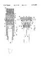
- FIG. 1is a simplified schematic representation of the electrical connector assembly embodying the present invention, showing the connector body in elevation and the seal member in cross section;
- FIG. 2is a cross-sectional view of the seal member embodying the present invention.
- FIG. 3is a cross-sectional view of the seal member and the body of the electrical connector embodying the present invention.
- FIG. 4is a cross-sectional view of the electrical connector embodying the present invention enclosed within a separable shell assembly
- FIG. 5is a cross-sectional of the electrical connector embodying the present invention wherein the body of the connector is the primary element of a pass-through assembly;
- FIG. 6is a cross-sectional of the seal member embodying the present invention in which the seal member includes a skirt adapted to extend over the entering cable assembly;
- FIG. 7is a cross-sectional view of another construction of the seal member embodying the present invention.
- FIG. 8is a cross-sectional view of an alternate embodiment of the seal member and the body of an electrical connector embodying the present invention.
- An electrical connector embodying the present inventionis generally indicated in the drawings by the reference numeral 10 which, as represented in FIG. 1 in simplified form, includes a body 12 and a seal member 14.
- the body 12has a cable entry end 16 and at least one, and more typically a plurality of, electrical conductors 18 disposed within the body 12, as best shown in FIGS. 3 and 4.
- the electrical conductors 18extend through the body 12 and have a portion 20 that additionally extends outwardly from the cable entry end 16 of the body 12, terminating at a distal end 22 that is adapted, for example with a conventional solder lug or crimp connector, for connection with an electrical lead 24 of a cable assembly 26.
- each of the outwardly extending portions 20 of the conductors 18are not only encapsulated within the body 12, but also are encapsulated, along a significant portion of the outwardly extending length, within a sheath 28 that is integrally formed with the body 12.
- the outer surface of each of the conductors, or contacts, 18have an outer surface that is defined along the encapsulated portion of the conductor 18, by a plurality of inwardly extending annular grooves 30 that aid in the retention of the conductor 18 within the body 12 and assure sealing of the conductor 18 with the body 12 and integral sheath 28.
- the opposite ends 32 of the conductors 18are typically shaped to provide a pin contact member, as illustrated in FIGS. 3 or 4, or a pin-receiving socket, not shown, or adapted for connection to a lead as shown in the pass-through arrangement of the present invention as illustrated in FIG. 5.
- Each of the conductor-surrounding sheaths 28have a substantially smooth outer surface that extends along and around the outwardly extending portion 20 of each of the conductors 18 from the cable entry end 16 of the body 12 to a position adjacent, but not covering, the adapted distal end 22 of the conductor.
- each of the sheaths 18have a length of about 0.400 in (1.02 cm) and an outer diameter of about 0.200 in (0.51 cm).
- the seal member 14has a first end 34 that is shaped to mate with, but not necessarily seal against, the cable entry end 16 of the body 12, and a second end 36 that is spaced from the first end 34.
- the seal member 14has at least one, and again typically a plurality of, internal passageways 38 that extend through the seal member 14 from the first end 34 to the second end 36.
- each of the internal passageways 38have a first portion 40 that extends inwardly from the first end 34 a distance substantially equal to the length of the outwardly extending portion 20 of the conductor 18.
- the first portion 40 of each of the internal passageways 38has an internal diameter along at least a portion of its length that is less than the predefined internal diameter of the sheath 28.
- the body 12, and accordingly the integrally formed sheaths 28, of the connector 10is formed of a relatively rigid, electrically nonconductive, thermoplastic material such as injection moldable glass-filled polyurethane.
- the seal member 14is formed of an electrically nonconductive, resiliently compressible thermoplastic material having a hardness less than that of the body 12 and sheath 28, such as a blend of polyethylene and neoprene rubber, having a hardness of about 40 to 70 durometer (Shore A).
- the seal member 14When the seal member 14 is formed of a compressible material having a hardness less than that of the sheath 28, it is desirable to provide a plurality of annular seals, arranged in serial order, along the mutually mating surfaces of the internal passageway 38 and the sheath 28.
- the first portion 40 of each of the internal passageways 38is defined by an internal wall comprising a plurality of annular alternating grooves 44 and compressibly deformable ridges 46 as best shown in FIG. 2.
- the deformable ridges 46desirably have a free, or nondeformed, internal diameter that is less than the predetermined outer diameter of the sheaths 28.
- the ridges 46have an internal diameter of about 0.150 in (0.38 cm), and the alternating grooves 44 have an internal diameter of about 0.205 in (0.52 cm).
- the ridges 46form a plurality of sealing rings around each of the sheaths 28 preventing the passage of water from the first end 34 of the seal member 14 to the distal end 22 of the conductor 18 at which the conductor is connected with a wire lead 24.
- the body 12 of the connector 10, and accordingly also the sheaths 28 surrounding the outwardly extending portion 20 of each of the conductors 18,is formed of a compressible electrically nonconductive material having a hardness less than that of a relatively rigid seal member.
- the first portion 40 of each of the internal passageways 38 in the seal member 14is preferably defined by a smooth bore as shown in FIG. 7.
- the smooth borehas an internal diameter somewhat less than the outer diameter of the sheath 28, whereby the first portion 40 of the passageway 38, as in the earlier embodiment, forms an interference fit around the sheath and provides a seal preventing the passage of water from the first end 34 of the seal 14 to the distal lead-attachment end 22 of the conductor.
- Each of the internal passageways 38also have a second portion 42 that extends inwardly from the second end 36 of the seal member 14.
- the second portion 42 of each of the internal passageways 38are adapted to provide an interference fit around the insulation jacket of each of the wire leads 24 that are inserted through the second portion 42 of the passageway 38 for electrical connection with the conductor 18 at the adapted distal end 22 of the conductor.
- the second portion 42 of the passagewayis defined by an internal wall comprising a plurality of annular alternating grooves 48 and compressibly deformable ridges 50 as best shown in FIG. 2.
- the deformable ridges 50 in the second portion 42 of the internal passageway 38have a free, or nondeformed, internal diameter that is less than the predetermined outer diameter of insulation jacket surrounding each of the electrical leads 24.
- the insulation jacket surrounding a No. 24AWG wiretypically has an outer diameter of about 0.050 in (1.27 mm).
- the inner diameter of the deformable ridges 50 in the second portion 42 of the internal passageway 38would preferably have an internal diameter of about 0.03 in (0.76 mm).
- the ridges 50advantageously form a plurality of sealing rings around each of the electrical leads 24 of a cable assembly 26 preventing the passage of water from the second end 36 of the seal member 14 to the distal end 22 of the conductor 18 at which the lead 24 is attached. Furthermore, it can be seen that even if the outer protective covering of the cable assembly 26 is breached by a tear, cut or other damage, even though water may be able to wick along the outer jacket of each of the leads 24 in the assembly 26, it will not be able to penetrate the seal member 14 to the connection point of each of the leads 26 with a respective conductor 18.
- the second portion 42 of the internal passageways 38may be defined by smooth bore surfaces, as illustrated in FIG. 7, wherein the internal diameter of the bore is slightly less than that of the insulation jacket of the wire leads 24.
- Insulation jackets for electrical conductorsare typically formed of a flexible and somewhat compressible material such a polyurethane and therefore can be drawn, with some resistance, through a slightly smaller diameter passageway and thereby form a watertight seal between the jacket and the wall of the passageway.
- the body 12 and the seal member 14 of the electrical connector 10may both be formed of relatively compressible materials.
- the internal passageway 38 extending through the body 12 and seal member 14may have either a smooth bore or annular compressible deformable ridges 46 provided in the first portion 40, or a smooth bore or annular compressible deformable ridges 50 formed in the second portion 42, or a combination of respective smooth bores and ridges.
- the seal member 14has a protective annular wall or skirt 52 that extends outwardly from the second end 36 of the seal member 14 as shown in FIG. 6.
- the skirt 52provides added support for the cable assembly 26 at a position near its end, or termination.
- the internal wall of the protective skirt 52desirably has a plurality of inwardly extending ridges 54 which have an internal diameter less than the outer diameter of the cable assembly 26.
- the ridges 54provide an additional seal around the outer jacket of the cable assembly 26.
- the electrical connector 10typically has a plurality of electrical conductors 18 arranged in a predetermined pattern and, accordingly, the seal member 14 includes a like plurality of passageways 38 arranged in the same predetermined pattern.
- the body 12may have an index pin and the seal member 14 provided with a suitable mating receiving port for the pin.
- the body 12 and seal member 14may include suitable key and mating keyway elements to aid alignment of the seal member 14 with the body 12 with the prearranged pattern of sheath-enclosed conductors 18 extending outwardly from the cable entry end 16 of the body 12.
- the seal member 14may be constructed of a compressible material and protectively covered within a protective case formed of a harder, relatively rigid material on its external circumferential surface.
- This bi-material constructional arrangementis described in association with the inter-connector coupling member defined in copending U.S. patent application Ser. No. 08/389,253, filed Feb. 16, 1995 by the inventor of the present invention and titled FIELD REPAIRABLE ELECTRICAL CONNECTOR.
- the body 12 of the electrical connector 10 embodying the present inventionmay have a construction adapted for interconnection with a mating connector, as illustrated in FIGS. 3 and 4, or be adapted as shown in FIG. 5 to provide a thru, or pass-through, assembly enabling electrical signals to be transmitted through the wall 56 of a panel or box enclosure without requiring a separable connector.
- the body 12advantageously has sheaths formed around the portion of the electrical conductor 18 that extends outwardly from the end of the body 12 spaced away from the cable entry end 16, and desirably includes a coupling member 62 between connectors as described in copending U.S. patent application Ser. No. 08/226,009, filed Apr. 11, 1994 by the inventor of the present invention and titled FIELD REPAIRABLE ELECTRICAL CONNECTOR.
- the body 12 of the connectoris mounted to the wall 56 by a retaining nut 64.
- the opposite ends of the conductors 18are adapted for connection with a lead or other electrical component and are generally enclosed within a sealed box, operating panel or other enclosure partially defined by the wall 56. There is, therefore, no requirement in this application for sealing the electrical connection at the internally disposed ends of the conductor 18.
- the connector 10 embodying the present inventionis typically enclosed within a conventional separable shell assembly 60.
- the shell assembly 60assures secure engagement of the seal member 14 with the body 12 and prevents inadvertent separation of the seal member 14 and body 12 after assembly and during subsequent use.
- the various components of the shell assembly 60are first positioned over the cable assembly 26.
- Individual wire leads 24are then individually separated from the cable assembly 26 and inserted one at a time into the second portion 42 of the seal member 14.
- the ends of the wire leads 24are then pushed, or pulled through the passageway 38 until there is a length of the lead wire 24 exposed that is sufficient to provide appropriate attachment to the adapted end 22 of the conductor 18.
- An appropriate portion of the insulating jacketis then stripped from the end the wire lead 24, and the bare wire end attached by soldering, crimping, twisting or other suitable method, to the adapted end 22 of the conductor 18.
- the seal member 14is then coupled with the body 12 by pushing the seal member 14 over the sheaths 28 simultaneously with pulling the excess length of the wire leads 24 from the second portion 42 of the passageway.
- the elements of the shell assembly 60, if used,are then brought over the assembled connector 10, and the electrical connector 10 embodying the present invention is ready for use.
- the seal member 14can be pulled away from the body 12, exposing the connection points of the wire leads 24 with the conductors 18. After completion of appropriate repairs, for example repair of the connection itself or substitution of a failed lead 24 with a previously unused lead 24 of the cable assembly 26, the seal member 14 and body 12 are reassembled as described above.
- the electrical connector 10 embodying the present inventionnot only provides an economical and simple method of sealing the cable entry end of an electrical connector, but also enables the electrical connector to be repaired in the field with conventional tools and equipment.
- the electrical connector 10 embodying the present inventionis particularly useful in underwater applications, such as seismic exploration, and in other applications where it is desirable to protect the connection of a wire lead with the conductor, such as in certain highly corrosive, volatile, or potentially explosive atmospheres.
- the electrical connector 10 embodying the present inventionis economical to produce and provides easy access to the important connection juncture of a wire lead with a conductor. Furthermore, the electrical connector 10 embodying the present invention provides an advantageous water seal around each wire lead of a cable assembly, and around each connection of each lead with a respective connector conductor. This arrangement, in cooperation with embedment of the connector conductors within an integrally formed body and sheath, effectively seals the cable entry end of the connector.
Landscapes
- Connector Housings Or Holding Contact Members (AREA)
Abstract
Description
Claims (11)
Priority Applications (2)
| Application Number | Priority Date | Filing Date | Title |
|---|---|---|---|
| US08/590,148US5711685A (en) | 1996-01-23 | 1996-01-23 | Electrical connector having removable seal at cable entry end |
| US08/884,562US5830011A (en) | 1996-01-23 | 1997-06-27 | Electrical connector having removable seal at cable entry end |
Applications Claiming Priority (1)
| Application Number | Priority Date | Filing Date | Title |
|---|---|---|---|
| US08/590,148US5711685A (en) | 1996-01-23 | 1996-01-23 | Electrical connector having removable seal at cable entry end |
Related Child Applications (1)
| Application Number | Title | Priority Date | Filing Date |
|---|---|---|---|
| US08/884,562ContinuationUS5830011A (en) | 1996-01-23 | 1997-06-27 | Electrical connector having removable seal at cable entry end |
Publications (1)
| Publication Number | Publication Date |
|---|---|
| US5711685Atrue US5711685A (en) | 1998-01-27 |
Family
ID=24361072
Family Applications (2)
| Application Number | Title | Priority Date | Filing Date |
|---|---|---|---|
| US08/590,148Expired - LifetimeUS5711685A (en) | 1996-01-23 | 1996-01-23 | Electrical connector having removable seal at cable entry end |
| US08/884,562Expired - LifetimeUS5830011A (en) | 1996-01-23 | 1997-06-27 | Electrical connector having removable seal at cable entry end |
Family Applications After (1)
| Application Number | Title | Priority Date | Filing Date |
|---|---|---|---|
| US08/884,562Expired - LifetimeUS5830011A (en) | 1996-01-23 | 1997-06-27 | Electrical connector having removable seal at cable entry end |
Country Status (1)
| Country | Link |
|---|---|
| US (2) | US5711685A (en) |
Cited By (20)
| Publication number | Priority date | Publication date | Assignee | Title |
|---|---|---|---|---|
| US5980317A (en)* | 1998-03-13 | 1999-11-09 | Geo Space Corporation | Repairable electrical geophysical connector |
| US5993272A (en)* | 1998-05-20 | 1999-11-30 | Tescorp Seismic Products, Inc. | Electrical connector having detachable wire connection at cable entry end |
| US6034923A (en)* | 1997-07-28 | 2000-03-07 | Marine Innovations, L.L.C. | Seismic sensor pod |
| US6062905A (en)* | 1997-02-19 | 2000-05-16 | Schlumberger Technology Corporation | Male pin connector |
| US6521160B2 (en)* | 1999-08-26 | 2003-02-18 | Yazaki Corporation | Multipolar waterproof connector |
| US20120274163A1 (en)* | 2011-04-27 | 2012-11-01 | Toyota Jidosha Kabushiki Kaisha | Power unit |
| US20130189867A1 (en)* | 2012-01-25 | 2013-07-25 | INOVA, Ltd. | Sealing feature for use with connectors |
| WO2014110333A1 (en)* | 2013-01-14 | 2014-07-17 | Deutsch Engineering Connecting Devices, Inc. | User configuratiojn connector |
| US20150144398A1 (en)* | 2013-11-26 | 2015-05-28 | Andrew Llc | Adapter for sealing cover for electrical interconnections |
| US9634427B2 (en) | 2014-04-04 | 2017-04-25 | Advanced Oilfield Innovations (AOI), Inc. | Shock and vibration resistant bulkhead connector with pliable contacts |
| US10027051B1 (en)* | 2017-02-20 | 2018-07-17 | Robert Bosch Gmbh | Hybrid electrical connector |
| US10524703B2 (en) | 2004-07-13 | 2020-01-07 | Dexcom, Inc. | Transcutaneous analyte sensor |
| US20200021053A1 (en)* | 2018-02-08 | 2020-01-16 | Anhui Zhongding Sealing Parts Co.,Ltd | Power connector |
| US10610136B2 (en) | 2005-03-10 | 2020-04-07 | Dexcom, Inc. | System and methods for processing analyte sensor data for sensor calibration |
| US10693254B2 (en)* | 2018-05-21 | 2020-06-23 | Japan Aviation Electronics Industry, Limited | Dummy pin |
| US10813577B2 (en) | 2005-06-21 | 2020-10-27 | Dexcom, Inc. | Analyte sensor |
| EP1986543B2 (en)† | 2006-02-22 | 2022-03-09 | DexCom, Inc. | Analyte sensor |
| US11918782B2 (en) | 2006-06-30 | 2024-03-05 | Abbott Diabetes Care Inc. | Integrated analyte sensor and infusion device and methods therefor |
| US12315630B2 (en) | 2009-08-31 | 2025-05-27 | Abbott Diabetes Care Inc. | Medical devices and methods |
| US12369821B2 (en) | 2018-06-07 | 2025-07-29 | Abbott Diabetes Care Inc. | Focused sterilization and sterilized sub-assemblies for analyte monitoring systems |
Families Citing this family (2)
| Publication number | Priority date | Publication date | Assignee | Title |
|---|---|---|---|---|
| US6716063B1 (en) | 2000-02-28 | 2004-04-06 | Pgs Exploration (Us), Inc. | Electrical cable insert |
| DE20006550U1 (en)* | 2000-04-08 | 2001-08-16 | Robert Bosch Gmbh, 70469 Stuttgart | Electrical connector |
Citations (45)
| Publication number | Priority date | Publication date | Assignee | Title |
|---|---|---|---|---|
| US2843133A (en)* | 1957-09-26 | 1958-07-15 | Jack L Barbara | Filter unit for pipes |
| US2881406A (en)* | 1955-06-20 | 1959-04-07 | Cannon Electric Co | Moisture seal for connectors |
| US3197730A (en)* | 1963-12-04 | 1965-07-27 | Richard L Hargett | Pressure-tight connector |
| US3449182A (en)* | 1966-05-16 | 1969-06-10 | Structural Fibers | Method of making a hollow,fiber-reinforced plastic pressure vessel |
| US3461529A (en)* | 1966-10-14 | 1969-08-19 | Textron Inc | Method of making a bearing |
| US3497864A (en)* | 1968-06-27 | 1970-02-24 | Us Navy | Underwater electrical cable connector |
| US3641479A (en)* | 1969-06-16 | 1972-02-08 | Obrien D G Inc | Underwater disconnectible connector |
| US3693133A (en)* | 1969-10-08 | 1972-09-19 | Inst Francais Du Petrole | Fluid tight electric connector |
| US3739330A (en)* | 1970-07-08 | 1973-06-12 | Mark Products | Geophone assembly |
| US3745511A (en)* | 1971-06-16 | 1973-07-10 | Mark Products | Multiconductor cable connector |
| US3783434A (en)* | 1972-08-10 | 1974-01-01 | Mark Iii Inc | Shielded cable coupler |
| US3888559A (en)* | 1972-04-13 | 1975-06-10 | Amp Inc | High voltage quick disconnect assembly |
| US3937545A (en)* | 1974-12-23 | 1976-02-10 | Ford Motor Company | Waterproof electrical connector |
| US3954154A (en)* | 1970-09-25 | 1976-05-04 | Kruppenbach John A | Towed land cable |
| US4032214A (en)* | 1976-04-21 | 1977-06-28 | Schlumberger Technology Corporation | Cable-termination assemblies and methods for manufacturing such assemblies |
| US4090759A (en)* | 1975-04-17 | 1978-05-23 | Amp Incorporated | Micro-miniature circular high voltage connector |
| US4150866A (en)* | 1977-08-26 | 1979-04-24 | Amp Incorporated | Environmentally sealed connector |
| US4284312A (en)* | 1978-12-21 | 1981-08-18 | Chrysler Corporation | Sealing type electrical connector |
| US4355855A (en)* | 1979-02-07 | 1982-10-26 | Dimitri Rebikoff | Deep water connector |
| US4445741A (en)* | 1981-10-13 | 1984-05-01 | Houston Geophysical Products, Inc. | Double-plug seismic connector |
| GB2131633A (en)* | 1982-12-13 | 1984-06-20 | Reed Products Inc | Underwater electrical cable connectors |
| US4480151A (en)* | 1982-07-19 | 1984-10-30 | Hilliard Dozier | Temperature stable hermetically sealed terminal |
| US4497531A (en)* | 1981-07-23 | 1985-02-05 | Amp Incorporated | Electrical connector |
| US4588247A (en)* | 1982-05-19 | 1986-05-13 | Souriau & C. | Electric connectors intended particularly to be used in a liquid medium particularly under pressure |
| US4589939A (en)* | 1984-02-17 | 1986-05-20 | Raychem Corporation | Insulating multiple-conductor cables using coated insert means |
| USH113H (en)* | 1986-01-27 | 1986-08-05 | Waterblock and strain relief for electrical connectors | |
| US4609247A (en)* | 1983-07-11 | 1986-09-02 | Houston Geophysical Products, Inc. | Connector having two seal-rings of different diameters |
| US4632482A (en)* | 1982-04-15 | 1986-12-30 | Allied Corporation | Contact for an electrical connector |
| US4758174A (en)* | 1987-01-20 | 1988-07-19 | Molex Incorporated | Environmentally sealed electrical connector |
| US4767356A (en)* | 1985-11-08 | 1988-08-30 | Souriau & Cie | Electrical connectors, particularly connectors fluid-tight on immersion in a liquid |
| US4767349A (en)* | 1983-12-27 | 1988-08-30 | Schlumberger Technology Corporation | Wet electrical connector |
| US4790768A (en)* | 1986-05-20 | 1988-12-13 | Total Compagnie Francaise Des Petroles | Immersible electrical coupling |
| US4820170A (en)* | 1984-12-20 | 1989-04-11 | Amp Incorporated | Layered elastomeric connector and process for its manufacture |
| US4861288A (en)* | 1987-12-14 | 1989-08-29 | Royal Technologies Usa, Inc. | Electrical cordset |
| US4921452A (en)* | 1988-08-22 | 1990-05-01 | Hilliard Dozier | Breakaway hermetically sealed electrical terminal |
| US5014813A (en)* | 1988-12-27 | 1991-05-14 | Fussell Don L | Water-proof geophone housing |
| US5120237A (en)* | 1991-07-22 | 1992-06-09 | Fussell Don L | Snap on cable connector |
| US5120268A (en)* | 1990-08-07 | 1992-06-09 | Al Gerrans | Marine electrical connector |
| US5130954A (en)* | 1991-07-22 | 1992-07-14 | Fussell Don L | Leader cable anchor for a geophone |
| US5145410A (en)* | 1990-08-06 | 1992-09-08 | Yazaki Corporation | Waterproof connector |
| US5183966A (en)* | 1990-11-19 | 1993-02-02 | Western Atlas International, Inc. | Termination assembly with improved waterblock |
| US5199893A (en)* | 1991-07-22 | 1993-04-06 | Fussell Don L | Seismic connector with replaceable seal |
| US5297974A (en)* | 1992-09-14 | 1994-03-29 | Fussell Don L | Positively released seismic cable connector |
| US5362258A (en)* | 1992-09-09 | 1994-11-08 | Wilo Gmbh | Cable-attaching device for a pump |
| US5387119A (en)* | 1993-10-08 | 1995-02-07 | Tescorp Seismic Products, Inc. | Waterproof electrical connector |
- 1996
- 1996-01-23USUS08/590,148patent/US5711685A/ennot_activeExpired - Lifetime
- 1997
- 1997-06-27USUS08/884,562patent/US5830011A/ennot_activeExpired - Lifetime
Patent Citations (46)
| Publication number | Priority date | Publication date | Assignee | Title |
|---|---|---|---|---|
| US2881406A (en)* | 1955-06-20 | 1959-04-07 | Cannon Electric Co | Moisture seal for connectors |
| US2843133A (en)* | 1957-09-26 | 1958-07-15 | Jack L Barbara | Filter unit for pipes |
| US3197730A (en)* | 1963-12-04 | 1965-07-27 | Richard L Hargett | Pressure-tight connector |
| US3449182A (en)* | 1966-05-16 | 1969-06-10 | Structural Fibers | Method of making a hollow,fiber-reinforced plastic pressure vessel |
| US3461529A (en)* | 1966-10-14 | 1969-08-19 | Textron Inc | Method of making a bearing |
| US3497864A (en)* | 1968-06-27 | 1970-02-24 | Us Navy | Underwater electrical cable connector |
| US3641479A (en)* | 1969-06-16 | 1972-02-08 | Obrien D G Inc | Underwater disconnectible connector |
| US3693133A (en)* | 1969-10-08 | 1972-09-19 | Inst Francais Du Petrole | Fluid tight electric connector |
| US3739330A (en)* | 1970-07-08 | 1973-06-12 | Mark Products | Geophone assembly |
| US3954154A (en)* | 1970-09-25 | 1976-05-04 | Kruppenbach John A | Towed land cable |
| US3745511A (en)* | 1971-06-16 | 1973-07-10 | Mark Products | Multiconductor cable connector |
| US3888559A (en)* | 1972-04-13 | 1975-06-10 | Amp Inc | High voltage quick disconnect assembly |
| US3783434A (en)* | 1972-08-10 | 1974-01-01 | Mark Iii Inc | Shielded cable coupler |
| US3937545A (en)* | 1974-12-23 | 1976-02-10 | Ford Motor Company | Waterproof electrical connector |
| US4090759A (en)* | 1975-04-17 | 1978-05-23 | Amp Incorporated | Micro-miniature circular high voltage connector |
| US4032214A (en)* | 1976-04-21 | 1977-06-28 | Schlumberger Technology Corporation | Cable-termination assemblies and methods for manufacturing such assemblies |
| US4150866A (en)* | 1977-08-26 | 1979-04-24 | Amp Incorporated | Environmentally sealed connector |
| US4284312A (en)* | 1978-12-21 | 1981-08-18 | Chrysler Corporation | Sealing type electrical connector |
| US4355855A (en)* | 1979-02-07 | 1982-10-26 | Dimitri Rebikoff | Deep water connector |
| US4497531A (en)* | 1981-07-23 | 1985-02-05 | Amp Incorporated | Electrical connector |
| US4445741A (en)* | 1981-10-13 | 1984-05-01 | Houston Geophysical Products, Inc. | Double-plug seismic connector |
| US4445741B1 (en)* | 1981-10-13 | 1991-06-04 | Houston Geophysical Products I | |
| US4632482A (en)* | 1982-04-15 | 1986-12-30 | Allied Corporation | Contact for an electrical connector |
| US4588247A (en)* | 1982-05-19 | 1986-05-13 | Souriau & C. | Electric connectors intended particularly to be used in a liquid medium particularly under pressure |
| US4480151A (en)* | 1982-07-19 | 1984-10-30 | Hilliard Dozier | Temperature stable hermetically sealed terminal |
| GB2131633A (en)* | 1982-12-13 | 1984-06-20 | Reed Products Inc | Underwater electrical cable connectors |
| US4609247A (en)* | 1983-07-11 | 1986-09-02 | Houston Geophysical Products, Inc. | Connector having two seal-rings of different diameters |
| US4767349A (en)* | 1983-12-27 | 1988-08-30 | Schlumberger Technology Corporation | Wet electrical connector |
| US4589939A (en)* | 1984-02-17 | 1986-05-20 | Raychem Corporation | Insulating multiple-conductor cables using coated insert means |
| US4820170A (en)* | 1984-12-20 | 1989-04-11 | Amp Incorporated | Layered elastomeric connector and process for its manufacture |
| US4767356A (en)* | 1985-11-08 | 1988-08-30 | Souriau & Cie | Electrical connectors, particularly connectors fluid-tight on immersion in a liquid |
| USH113H (en)* | 1986-01-27 | 1986-08-05 | Waterblock and strain relief for electrical connectors | |
| US4790768A (en)* | 1986-05-20 | 1988-12-13 | Total Compagnie Francaise Des Petroles | Immersible electrical coupling |
| US4758174A (en)* | 1987-01-20 | 1988-07-19 | Molex Incorporated | Environmentally sealed electrical connector |
| US4861288A (en)* | 1987-12-14 | 1989-08-29 | Royal Technologies Usa, Inc. | Electrical cordset |
| US4921452A (en)* | 1988-08-22 | 1990-05-01 | Hilliard Dozier | Breakaway hermetically sealed electrical terminal |
| US5014813A (en)* | 1988-12-27 | 1991-05-14 | Fussell Don L | Water-proof geophone housing |
| US5145410A (en)* | 1990-08-06 | 1992-09-08 | Yazaki Corporation | Waterproof connector |
| US5120268A (en)* | 1990-08-07 | 1992-06-09 | Al Gerrans | Marine electrical connector |
| US5183966A (en)* | 1990-11-19 | 1993-02-02 | Western Atlas International, Inc. | Termination assembly with improved waterblock |
| US5130954A (en)* | 1991-07-22 | 1992-07-14 | Fussell Don L | Leader cable anchor for a geophone |
| US5120237A (en)* | 1991-07-22 | 1992-06-09 | Fussell Don L | Snap on cable connector |
| US5199893A (en)* | 1991-07-22 | 1993-04-06 | Fussell Don L | Seismic connector with replaceable seal |
| US5362258A (en)* | 1992-09-09 | 1994-11-08 | Wilo Gmbh | Cable-attaching device for a pump |
| US5297974A (en)* | 1992-09-14 | 1994-03-29 | Fussell Don L | Positively released seismic cable connector |
| US5387119A (en)* | 1993-10-08 | 1995-02-07 | Tescorp Seismic Products, Inc. | Waterproof electrical connector |
Cited By (61)
| Publication number | Priority date | Publication date | Assignee | Title |
|---|---|---|---|---|
| US6062905A (en)* | 1997-02-19 | 2000-05-16 | Schlumberger Technology Corporation | Male pin connector |
| AU744345B2 (en)* | 1997-02-19 | 2002-02-21 | Schlumberger Technology B.V. | Male pin connector |
| US6034923A (en)* | 1997-07-28 | 2000-03-07 | Marine Innovations, L.L.C. | Seismic sensor pod |
| US5980317A (en)* | 1998-03-13 | 1999-11-09 | Geo Space Corporation | Repairable electrical geophysical connector |
| US5993272A (en)* | 1998-05-20 | 1999-11-30 | Tescorp Seismic Products, Inc. | Electrical connector having detachable wire connection at cable entry end |
| US6521160B2 (en)* | 1999-08-26 | 2003-02-18 | Yazaki Corporation | Multipolar waterproof connector |
| US10980452B2 (en) | 2004-07-13 | 2021-04-20 | Dexcom, Inc. | Analyte sensor |
| US11883164B2 (en) | 2004-07-13 | 2024-01-30 | Dexcom, Inc. | System and methods for processing analyte sensor data for sensor calibration |
| US11045120B2 (en) | 2004-07-13 | 2021-06-29 | Dexcom, Inc. | Analyte sensor |
| US11026605B1 (en) | 2004-07-13 | 2021-06-08 | Dexcom, Inc. | Analyte sensor |
| US10993642B2 (en) | 2004-07-13 | 2021-05-04 | Dexcom, Inc. | Analyte sensor |
| US10993641B2 (en) | 2004-07-13 | 2021-05-04 | Dexcom, Inc. | Analyte sensor |
| US10709363B2 (en) | 2004-07-13 | 2020-07-14 | Dexcom, Inc. | Analyte sensor |
| US10932700B2 (en) | 2004-07-13 | 2021-03-02 | Dexcom, Inc. | Analyte sensor |
| US10918314B2 (en) | 2004-07-13 | 2021-02-16 | Dexcom, Inc. | Analyte sensor |
| US11064917B2 (en) | 2004-07-13 | 2021-07-20 | Dexcom, Inc. | Analyte sensor |
| US10918315B2 (en) | 2004-07-13 | 2021-02-16 | Dexcom, Inc. | Analyte sensor |
| US10918313B2 (en) | 2004-07-13 | 2021-02-16 | Dexcom, Inc. | Analyte sensor |
| US10524703B2 (en) | 2004-07-13 | 2020-01-07 | Dexcom, Inc. | Transcutaneous analyte sensor |
| US10827956B2 (en) | 2004-07-13 | 2020-11-10 | Dexcom, Inc. | Analyte sensor |
| US10813576B2 (en) | 2004-07-13 | 2020-10-27 | Dexcom, Inc. | Analyte sensor |
| US10799159B2 (en) | 2004-07-13 | 2020-10-13 | Dexcom, Inc. | Analyte sensor |
| US10799158B2 (en) | 2004-07-13 | 2020-10-13 | Dexcom, Inc. | Analyte sensor |
| US10722152B2 (en) | 2004-07-13 | 2020-07-28 | Dexcom, Inc. | Analyte sensor |
| US10709362B2 (en) | 2004-07-13 | 2020-07-14 | Dexcom, Inc. | Analyte sensor |
| US10918317B2 (en) | 2005-03-10 | 2021-02-16 | Dexcom, Inc. | System and methods for processing analyte sensor data for sensor calibration |
| US10610136B2 (en) | 2005-03-10 | 2020-04-07 | Dexcom, Inc. | System and methods for processing analyte sensor data for sensor calibration |
| US10709364B2 (en) | 2005-03-10 | 2020-07-14 | Dexcom, Inc. | System and methods for processing analyte sensor data for sensor calibration |
| US10925524B2 (en) | 2005-03-10 | 2021-02-23 | Dexcom, Inc. | System and methods for processing analyte sensor data for sensor calibration |
| US10716498B2 (en) | 2005-03-10 | 2020-07-21 | Dexcom, Inc. | System and methods for processing analyte sensor data for sensor calibration |
| US10617336B2 (en) | 2005-03-10 | 2020-04-14 | Dexcom, Inc. | System and methods for processing analyte sensor data for sensor calibration |
| US10743801B2 (en) | 2005-03-10 | 2020-08-18 | Dexcom, Inc. | System and methods for processing analyte sensor data for sensor calibration |
| US10610135B2 (en) | 2005-03-10 | 2020-04-07 | Dexcom, Inc. | System and methods for processing analyte sensor data for sensor calibration |
| US10610137B2 (en) | 2005-03-10 | 2020-04-07 | Dexcom, Inc. | System and methods for processing analyte sensor data for sensor calibration |
| US11000213B2 (en) | 2005-03-10 | 2021-05-11 | Dexcom, Inc. | System and methods for processing analyte sensor data for sensor calibration |
| US10918318B2 (en) | 2005-03-10 | 2021-02-16 | Dexcom, Inc. | System and methods for processing analyte sensor data for sensor calibration |
| US11051726B2 (en) | 2005-03-10 | 2021-07-06 | Dexcom, Inc. | System and methods for processing analyte sensor data for sensor calibration |
| US10918316B2 (en) | 2005-03-10 | 2021-02-16 | Dexcom, Inc. | System and methods for processing analyte sensor data for sensor calibration |
| US10856787B2 (en) | 2005-03-10 | 2020-12-08 | Dexcom, Inc. | System and methods for processing analyte sensor data for sensor calibration |
| US10898114B2 (en) | 2005-03-10 | 2021-01-26 | Dexcom, Inc. | System and methods for processing analyte sensor data for sensor calibration |
| US10813577B2 (en) | 2005-06-21 | 2020-10-27 | Dexcom, Inc. | Analyte sensor |
| EP1986543B2 (en)† | 2006-02-22 | 2022-03-09 | DexCom, Inc. | Analyte sensor |
| US11918782B2 (en) | 2006-06-30 | 2024-03-05 | Abbott Diabetes Care Inc. | Integrated analyte sensor and infusion device and methods therefor |
| US12315630B2 (en) | 2009-08-31 | 2025-05-27 | Abbott Diabetes Care Inc. | Medical devices and methods |
| US20120274163A1 (en)* | 2011-04-27 | 2012-11-01 | Toyota Jidosha Kabushiki Kaisha | Power unit |
| US20130189867A1 (en)* | 2012-01-25 | 2013-07-25 | INOVA, Ltd. | Sealing feature for use with connectors |
| US8992243B2 (en)* | 2012-01-25 | 2015-03-31 | Inova Ltd. | Sealing feature for use with connectors |
| WO2013112880A1 (en)* | 2012-01-25 | 2013-08-01 | Inova Ltd. | Sealing feature for use with connectors |
| US8790129B1 (en) | 2013-01-14 | 2014-07-29 | Deutsch Engineered Connecting Devices, Inc. | User configurable connector |
| EP2755283A3 (en)* | 2013-01-14 | 2014-08-06 | Deutsch Engineered Connecting Devices, Inc. | User Configurable Connector |
| WO2014110333A1 (en)* | 2013-01-14 | 2014-07-17 | Deutsch Engineering Connecting Devices, Inc. | User configuratiojn connector |
| US20150144398A1 (en)* | 2013-11-26 | 2015-05-28 | Andrew Llc | Adapter for sealing cover for electrical interconnections |
| US10404048B2 (en)* | 2013-11-26 | 2019-09-03 | Commscope Technologies Llc | Adapter for sealing cover for electrical interconnections |
| US9634427B2 (en) | 2014-04-04 | 2017-04-25 | Advanced Oilfield Innovations (AOI), Inc. | Shock and vibration resistant bulkhead connector with pliable contacts |
| US10651591B2 (en) | 2014-04-04 | 2020-05-12 | AOI (Advanced Oilfield Innovations, Inc.) | Shock and vibration resistant bulkhead connector with pliable contacts |
| US10027051B1 (en)* | 2017-02-20 | 2018-07-17 | Robert Bosch Gmbh | Hybrid electrical connector |
| US10411392B2 (en)* | 2017-02-20 | 2019-09-10 | Robert Bosch Gmbh | Hybrid electrical connector |
| US20200021053A1 (en)* | 2018-02-08 | 2020-01-16 | Anhui Zhongding Sealing Parts Co.,Ltd | Power connector |
| US10819061B2 (en)* | 2018-02-08 | 2020-10-27 | Anhui Zhongding Sealing Parts Co., Ltd | Power connector |
| US10693254B2 (en)* | 2018-05-21 | 2020-06-23 | Japan Aviation Electronics Industry, Limited | Dummy pin |
| US12369821B2 (en) | 2018-06-07 | 2025-07-29 | Abbott Diabetes Care Inc. | Focused sterilization and sterilized sub-assemblies for analyte monitoring systems |
Also Published As
| Publication number | Publication date |
|---|---|
| US5830011A (en) | 1998-11-03 |
Similar Documents
| Publication | Publication Date | Title |
|---|---|---|
| US5711685A (en) | Electrical connector having removable seal at cable entry end | |
| EP1269582B1 (en) | Data signal connector with protective overmold | |
| US6482036B1 (en) | Waterproof electrical connector | |
| US5984724A (en) | Waterproof low temperature geophysical connector | |
| US6165013A (en) | Method and apparatus waterproofing | |
| EP0730322B1 (en) | Underwater electrical connector | |
| EP3164912B1 (en) | Connector assembly and manufacturing method thereof | |
| CA2243838C (en) | An insulating enclosure to provide a water-tight seal with an electric connector | |
| US5797761A (en) | Power connector assembly | |
| EP0676829B1 (en) | Field repairable electrical connector | |
| US5704799A (en) | Field repairable electrical connector | |
| US4674807A (en) | Shielded connector | |
| EP2452402B1 (en) | High strength electrical connector | |
| KR101984729B1 (en) | Method for manufacturing cable connector having double insert molding structure, and a cable connector manufactured thereby | |
| EP0727845B1 (en) | Field repairable electrical connector | |
| US20220050249A1 (en) | Two-part and terminal connectors with conductor management device for use in hazardous environments | |
| US4198110A (en) | Connector | |
| US3685006A (en) | Cable connector | |
| US5821461A (en) | Waterproof splice for cables having different insulation materials and method of making same | |
| US20230344153A1 (en) | Cable termination and method | |
| US5104340A (en) | Corrosion resistant electrical connector | |
| US2839636A (en) | Electrical connection | |
| EP0959527B1 (en) | Electrical connector having detachable wire connection at cable entry end | |
| US20030199196A1 (en) | Press fit electrical connector assembly | |
| US6203023B1 (en) | Cable inlet |
Legal Events
| Date | Code | Title | Description |
|---|---|---|---|
| AS | Assignment | Owner name:TESCORP SEISMIC PRODUCTS, INC., TEXAS Free format text:ASSIGNMENT OF ASSIGNORS INTEREST;ASSIGNOR:WOOD, RICHARD G.;REEL/FRAME:007844/0445 Effective date:19960118 | |
| STCF | Information on status: patent grant | Free format text:PATENTED CASE | |
| AS | Assignment | Owner name:INPUT/OUTPUT, INC., A CORP. OF DELAWARE, TEXAS Free format text:ASSIGNMENT OF ASSIGNORS INTEREST;ASSIGNOR:TESCORP SEISMIC PRODUCTS, INC., A CORP. OF DELAWARE;REEL/FRAME:009893/0872 Effective date:19990330 | |
| FPAY | Fee payment | Year of fee payment:4 | |
| FPAY | Fee payment | Year of fee payment:8 | |
| FPAY | Fee payment | Year of fee payment:12 | |
| AS | Assignment | Owner name:ION GEOPHYSICAL CORPORATION,TEXAS Free format text:CHANGE OF NAME;ASSIGNOR:INPUT/OUTPUT, INC.;REEL/FRAME:024424/0191 Effective date:20070924 Owner name:INOVA GEOPHYSICAL CORPORATION,TEXAS Free format text:ASSIGNMENT OF ASSIGNORS INTEREST;ASSIGNOR:ION GEOPHYSICAL CORPORATION;REEL/FRAME:024424/0138 Effective date:20100519 Owner name:INOVA GEOPHYSICAL CORPORATION, TEXAS Free format text:ASSIGNMENT OF ASSIGNORS INTEREST;ASSIGNOR:ION GEOPHYSICAL CORPORATION;REEL/FRAME:024424/0138 Effective date:20100519 | |
| AS | Assignment | Owner name:INOVA LTD., CAYMAN ISLANDS Free format text:ASSIGNMENT OF ASSIGNORS INTEREST;ASSIGNOR:ION GEOPHYSICAL CORPORATION;REEL/FRAME:024651/0695 Effective date:20100707 |