US5711679A - Shielded memory card connector - Google Patents
Shielded memory card connectorDownload PDFInfo
- Publication number
- US5711679A US5711679AUS08/752,756US75275696AUS5711679AUS 5711679 AUS5711679 AUS 5711679AUS 75275696 AUS75275696 AUS 75275696AUS 5711679 AUS5711679 AUS 5711679A
- Authority
- US
- United States
- Prior art keywords
- memory card
- card connector
- circuit board
- connector
- extending pins
- Prior art date
- Legal status (The legal status is an assumption and is not a legal conclusion. Google has not performed a legal analysis and makes no representation as to the accuracy of the status listed.)
- Expired - Lifetime
Links
Images


Classifications
- H—ELECTRICITY
- H01—ELECTRIC ELEMENTS
- H01R—ELECTRICALLY-CONDUCTIVE CONNECTIONS; STRUCTURAL ASSOCIATIONS OF A PLURALITY OF MUTUALLY-INSULATED ELECTRICAL CONNECTING ELEMENTS; COUPLING DEVICES; CURRENT COLLECTORS
- H01R12/00—Structural associations of a plurality of mutually-insulated electrical connecting elements, specially adapted for printed circuits, e.g. printed circuit boards [PCB], flat or ribbon cables, or like generally planar structures, e.g. terminal strips, terminal blocks; Coupling devices specially adapted for printed circuits, flat or ribbon cables, or like generally planar structures; Terminals specially adapted for contact with, or insertion into, printed circuits, flat or ribbon cables, or like generally planar structures
- H01R12/50—Fixed connections
- H01R12/51—Fixed connections for rigid printed circuits or like structures
- H—ELECTRICITY
- H01—ELECTRIC ELEMENTS
- H01R—ELECTRICALLY-CONDUCTIVE CONNECTIONS; STRUCTURAL ASSOCIATIONS OF A PLURALITY OF MUTUALLY-INSULATED ELECTRICAL CONNECTING ELEMENTS; COUPLING DEVICES; CURRENT COLLECTORS
- H01R12/00—Structural associations of a plurality of mutually-insulated electrical connecting elements, specially adapted for printed circuits, e.g. printed circuit boards [PCB], flat or ribbon cables, or like generally planar structures, e.g. terminal strips, terminal blocks; Coupling devices specially adapted for printed circuits, flat or ribbon cables, or like generally planar structures; Terminals specially adapted for contact with, or insertion into, printed circuits, flat or ribbon cables, or like generally planar structures
- H01R12/70—Coupling devices
- H01R12/71—Coupling devices for rigid printing circuits or like structures
- H01R12/72—Coupling devices for rigid printing circuits or like structures coupling with the edge of the rigid printed circuits or like structures
- H01R12/73—Coupling devices for rigid printing circuits or like structures coupling with the edge of the rigid printed circuits or like structures connecting to other rigid printed circuits or like structures
- H—ELECTRICITY
- H01—ELECTRIC ELEMENTS
- H01R—ELECTRICALLY-CONDUCTIVE CONNECTIONS; STRUCTURAL ASSOCIATIONS OF A PLURALITY OF MUTUALLY-INSULATED ELECTRICAL CONNECTING ELEMENTS; COUPLING DEVICES; CURRENT COLLECTORS
- H01R12/00—Structural associations of a plurality of mutually-insulated electrical connecting elements, specially adapted for printed circuits, e.g. printed circuit boards [PCB], flat or ribbon cables, or like generally planar structures, e.g. terminal strips, terminal blocks; Coupling devices specially adapted for printed circuits, flat or ribbon cables, or like generally planar structures; Terminals specially adapted for contact with, or insertion into, printed circuits, flat or ribbon cables, or like generally planar structures
- H01R12/70—Coupling devices
- H01R12/71—Coupling devices for rigid printing circuits or like structures
- H01R12/712—Coupling devices for rigid printing circuits or like structures co-operating with the surface of the printed circuit or with a coupling device exclusively provided on the surface of the printed circuit
- H—ELECTRICITY
- H01—ELECTRIC ELEMENTS
- H01R—ELECTRICALLY-CONDUCTIVE CONNECTIONS; STRUCTURAL ASSOCIATIONS OF A PLURALITY OF MUTUALLY-INSULATED ELECTRICAL CONNECTING ELEMENTS; COUPLING DEVICES; CURRENT COLLECTORS
- H01R13/00—Details of coupling devices of the kinds covered by groups H01R12/70 or H01R24/00 - H01R33/00
- H01R13/648—Protective earth or shield arrangements on coupling devices, e.g. anti-static shielding
- H01R13/658—High frequency shielding arrangements, e.g. against EMI [Electro-Magnetic Interference] or EMP [Electro-Magnetic Pulse]
- H—ELECTRICITY
- H01—ELECTRIC ELEMENTS
- H01R—ELECTRICALLY-CONDUCTIVE CONNECTIONS; STRUCTURAL ASSOCIATIONS OF A PLURALITY OF MUTUALLY-INSULATED ELECTRICAL CONNECTING ELEMENTS; COUPLING DEVICES; CURRENT COLLECTORS
- H01R12/00—Structural associations of a plurality of mutually-insulated electrical connecting elements, specially adapted for printed circuits, e.g. printed circuit boards [PCB], flat or ribbon cables, or like generally planar structures, e.g. terminal strips, terminal blocks; Coupling devices specially adapted for printed circuits, flat or ribbon cables, or like generally planar structures; Terminals specially adapted for contact with, or insertion into, printed circuits, flat or ribbon cables, or like generally planar structures
- H01R12/70—Coupling devices
- H01R12/71—Coupling devices for rigid printing circuits or like structures
- H01R12/72—Coupling devices for rigid printing circuits or like structures coupling with the edge of the rigid printed circuits or like structures
- H01R12/721—Coupling devices for rigid printing circuits or like structures coupling with the edge of the rigid printed circuits or like structures cooperating directly with the edge of the rigid printed circuits
- H—ELECTRICITY
- H01—ELECTRIC ELEMENTS
- H01R—ELECTRICALLY-CONDUCTIVE CONNECTIONS; STRUCTURAL ASSOCIATIONS OF A PLURALITY OF MUTUALLY-INSULATED ELECTRICAL CONNECTING ELEMENTS; COUPLING DEVICES; CURRENT COLLECTORS
- H01R13/00—Details of coupling devices of the kinds covered by groups H01R12/70 or H01R24/00 - H01R33/00
- H01R13/62—Means for facilitating engagement or disengagement of coupling parts or for holding them in engagement
- H01R13/629—Additional means for facilitating engagement or disengagement of coupling parts, e.g. aligning or guiding means, levers, gas pressure electrical locking indicators, manufacturing tolerances
- H01R13/633—Additional means for facilitating engagement or disengagement of coupling parts, e.g. aligning or guiding means, levers, gas pressure electrical locking indicators, manufacturing tolerances for disengagement only
Definitions
- This inventionrelates to electrical connectors, and more particularly, to memory card connectors for use in notebook computers, PC printers and palmtop computers which can expand the space under the connector for installing electronic components and can be maintained easily.
- the memory card connector of the present inventionmay be detachably mounted on a mainboard.
- the memory card connectorcomprises a header and a carrier connected to the header, wherein the header is provided with a plurality of pins extended in both inward and outward directions, and a vertical circuit board is electrically and securely connected to the outward pins of the header.
- the lower end of the circuit boardis detachably inserted into a connector of the mainboard.
- the height of the circuit board of the connectorcan also be set according to the requirement of a specific application of the connector so that the space (stand-off) between the connector and the mainboard can be properly utilized.
- meansmay also be provided for shielding the outward pins.
- the shielding meanswill be grounded to the mainboard by means of a grounding plane which is interposed between two signal planes at equal distances in spaced, parallel relation. A portion of the pins are connected to one signal plane while the rest of the pins are connected to the other signal plane to achieve effective impedance control.
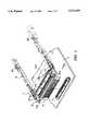
- FIG. 1is an exploded view of a memory card connector and its associated mainboard according to the present invention
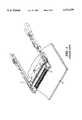
- FIG. 2is a side elevational view of a second embodiment of the invention illustrating a memory card connector installed on a mainboard according to the present invention
- FIG. 3is a side elevational view illustrating two memory card connectors stacked together and installed on a mainboard according to the present invention
- FIG. 4is a perspective view illustrating a conventional memory connector installed on a mainboard
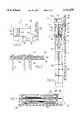
- FIG. 5is a top plan view of a memory card connector representing a third preferred embodiment of the present invention.
- FIG. 6is a side elevational view from line VI--VI of the memory card connector shown in FIG. 5;
- FIG. 7is a front end view from line VII--VII of the memory card connector shown in FIG. 6;
- FIG. 8is a detailed enlarged view of area VIII in FIG. 6;
- FIG. 9is a detailed cross sectional view of area IX in FIG. 8;
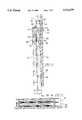
- FIG. 10is a top plan view of a memory card connector representing a preferred embodiment of the present invention.
- FIG. 11is a side elevational view from line XI--XI of the memory card connector shown in FIG. 10;
- FIG. 12is an end view from line XII--XII of the memory card connector shown in FIG. 10.
- a memory card connector 1according to the present invention comprises a header 10 and a carrier 12 connected to the header 10.
- the connection between the header 10 and the carrier 12can be fixed or separated in the known manner, which is not the characteristic feature of the invention and is omitted in the description hereinafter.
- the header 10is provided with a plurality of pins 101 extended in both inward and outward directions.
- the inward pins 101 extending from the inward edge 102 of the headerare used for inserting a memory card (not shown) to be received in the carrier 12.
- a vertical circuit board 14is electrically and securely connected to the outward pins 103 extending from the outward edge 104 of the header 10.
- a connector 3is securely mounted to the surface of a mainboard 2 for mounting the memory card connector 1.
- the lower end of the vertical circuit board 14is detachably inserted into the connector 3 to effect electrical connection.
- the lower end of the circuit board 14is directly plugged to the connector 3 and the bottom of connector 1 is horizontally supported by four studs 21 provided on the mainboard 2.
- the connector 1can be fastened to the studs 21 by using screws (not shown) respectively received in the four studs 21 passing through four screw mounting holes 120 of connector 1.
- the height of the circuit board 14is set according to the requirement of a specific application of the memory card connector so that the space between the memory card connector 1 and the mainboard 2 can be properly utilized.
- FIG. 3two memory card connectors 1 and 1' are stacked together and installed on the mainboard 2.
- the outward pins 103' of the upper connector 1'are longer than the outward pins 103 of the lower connector 1.
- Circuit board 14' in the upper connector 1'is larger to fit the real height as required.
- Two vertical circuit boards 14' and 14 respectively connected to the upper and lower connectors 1' and 1are detachably and vertically connected to two corresponding connectors 3' and 3 of the mainboard 2 separately.
- FIG. 4a conventional memory connector 4 installed on a mainboard 5 is illustrated.
- the connector 4comprises a plurality of bending pins 41 which are directly soldered to the mainboard 5 by using SMT.
- SMTserial to metal bus
- FIGS. 5-8there is shown a composite of stacked memory card connectors 201 and 201' according to another embodiment of the present invention comprises headers 210' and 210 and carriers 212' and 212 connected respectively to the headers 210' and 210. Similar to the embodiment shown in FIG. 3, two memory card connectors 201 and 201' are stacked together and installed on a mainboard 202. As with the first two embodiments, the connection between the header and the carrier can be fixed or separated in the known manner, which is not the characteristic feature of the invention and is omitted in the description hereinafter.
- the headeris provided with a plurality of pins extending in both directions as in an inward direction 328' and in an outward direction as at 330' and 332' and 330 and 332.
- the inward pins extending from the inward edge of the headerare used for inserting memory cards shown as at 216' in phantom lines in FIG. 5 to be received in the carrier.
- Vertical circuit boards 214' and 214are electrically and securely connected to the outward pins extending from the outward edge of the header.
- connectors 203' and 203are securely mounted to the surface of a mainboard for mounting the memory card connector.
- a suitable connectorwould be one of the CONAN series receptacles available from Berg Electronics, Inc. of St. Louis, Mo.
- ground plane connection between the vertical circuit board and the connectorwill preferably be generally equally distributed over the connector length.
- the lower end of the vertical circuit boardis detachably inserted into the connector to effect electrical connection.
- the lower end of the circuit board 214'is directly plugged to the connector 203' and the lower end of circuit board 214 is directly plugged into the connector 203.
- the bottom of connector 201 and 201'are horizontally supported by four studs 333, 334, 336 and 338 provided on the mainboard.
- the connectorcan be fastened to the studs by using screws 340, 342, 344 and 346 respectively received in the four studs passing through four screw mounting holes as at 320 of the connector.
- the height of the circuit board 214'is set according to the requirement of a specific application of the memory card connector so that the space between the memory card connector and the mainboard can be properly utilized. It will also be seen that lower and upper memory card connectors 201 and 201' are stacked together to be installed over the mainboard.
- the outward upper pins as at 203' of the upper connector 201'are connected to the vertical board 214'.
- a conductive ground shield 322'overlaps the pins as at 330' and 332' extending from connector 201'.
- Another conductive ground shield 322overlaps the pins as at 330 and 332 and separates those lower pins from the upper pins as at 330' and 332'.
- the vertical circuit board 214'has a central metallic ground plane 350' and opposed lateral metallic signal planes 352' and 354' which are parallel to and spaced from ground plane 350' at equal distances. These ground and signal planes extend downwardly to connector 203' to effect grounding and connection respectively to the mainboard. It will also be observed that the conductive shield 322' is isolated from signal planes 352' and 354' and contacts ground plane 350' to be grounded through that ground plane and connector 203' to the mainboard.
- pin 330'is isolated from ground plane 350' and signal plane 354' to contact signal plane 352' and to be connected through that signal plane 352' and connector 203' to the mainboard.
- Pin 332'is also isolated from ground plane 350' and signal plane 352' to contact signal plane 354' to be connected through that signal plane 354' and connector 203' to the mainboard. It will also be understood that the other outwardly extending pins which are horizontally aligned with pin 330' will contact and be connected to the mainboard through signal plane 352' and the other outwardly extending pins which are horizontally aligned with pin 332' will contact and be connected to the mainboard through signal plane 354'.
- shield 322 and pins 330 and 322are each connected to one of said separate parallel signal planes for impedance controlled grounding and signal transmission to the mainboard.
- the use of a medial ground plane with such equally spaced parallel lateral signal planesgenerally allows sufficient impedance control so that various heights of the vertical boards can be used without adversely affecting performance.
- Both shields 322 and 322' shieldsare connected to an adjacent memory card by means of fingers as at 326 and 326'. This connection is preferably in accordance with the PCMCIA/JEIDA PC standard released February, 1995 (Document No. 0295-03-1500).
- FIGS. 10-12another composite of stacked memory card connectors 401 and 401' is shown.
- carriers 412 and 412'are connected respectively to headers 410 and 410'.
- Memory card connectors 401 and 401'are stacked together and installed on a mainboard 402.
- the connection between the header and the carriercan be fixed or separated in the known manner.
- the headeris provided with a plurality of pins extending in both inward and outward directions. The inward pins extending from the inward edge of the header are used for inserting memory cards as at shown in FIG. 10 in phantom lines at 416' to be received in the carrier.
- a horizontal circuit board 414is electrically and securely connected to outward pins as at 530' and 530 extending respectively from the outward edges of both headers 410' and 410.
- a plug 404is securely mounted to the surface of a mainboard 402 for mounting the memory card connector.
- the bottom side of the horizontal circuit boardis soldered to a receptacle 403 which is engaged with plug 404 to effect electrical connection between board 414 and the mainboard.
- the bottom of connectors 401 and 401'are horizontally supported by four studs 533, 534, 536 and 538 provided on the mainboard.
- the connectorscan be fastened to the studs by using screws 540, 542, 544 and 536 respectively received in the four studs passing through four screw mounting holes as at 520 of the connector.
- the horizontal circuit board 414may be constructed similar to the vertical circuit board 214' described above with a medial ground plane interposed between parallel, equally spaced signal planes. It will also be seen that lower and upper memory card connectors 401 and 401' are stacked together to be installed over the mainboard. The outward upper pins as at 530' of the upper connector 401' extends diagonally downwardly to engage the horizontal board 414. Lower pins as at 530 from the lower board 401 extend diagonally upwardly to engage the horizontal circuit board.
- a conductive ground shield 522'overlaps the pins as at 530' extending from connector 401'.
- Another conductive ground shield 522overlaps the pins as at 530 and separates those lower pins from the upper pins as at 530'.
- the upper and lower pinscontact conductive pads respectively on the top and bottom surfaces of the horizontal circuit board and then to the signal planes.
- the shieldscontact conductive pads on the top and bottom surfaces of the horizontal circuit board and are then connected to the medial ground plane in the horizontal circuit board.
- Both shields 530' and 530are connected to an adjacent memory card by means of fingers as at 526 and 526'. This connection is preferably in accordance with the PCMCIA/JEIDA PC standard released February, 1995 (Document No. 0295-03-1500).
Landscapes
- Coupling Device And Connection With Printed Circuit (AREA)
- Details Of Connecting Devices For Male And Female Coupling (AREA)
- Credit Cards Or The Like (AREA)
Abstract
Description
Claims (21)
Priority Applications (1)
| Application Number | Priority Date | Filing Date | Title |
|---|---|---|---|
| US08/752,756US5711679A (en) | 1995-01-06 | 1996-11-20 | Shielded memory card connector |
Applications Claiming Priority (3)
| Application Number | Priority Date | Filing Date | Title |
|---|---|---|---|
| US36961495A | 1995-01-06 | 1995-01-06 | |
| US48792295A | 1995-07-11 | 1995-07-11 | |
| US08/752,756US5711679A (en) | 1995-01-06 | 1996-11-20 | Shielded memory card connector |
Related Parent Applications (1)
| Application Number | Title | Priority Date | Filing Date |
|---|---|---|---|
| US48792295AContinuation | 1995-01-06 | 1995-07-11 |
Publications (1)
| Publication Number | Publication Date |
|---|---|
| US5711679Atrue US5711679A (en) | 1998-01-27 |
Family
ID=27004648
Family Applications (1)
| Application Number | Title | Priority Date | Filing Date |
|---|---|---|---|
| US08/752,756Expired - LifetimeUS5711679A (en) | 1995-01-06 | 1996-11-20 | Shielded memory card connector |
Country Status (7)
| Country | Link |
|---|---|
| US (1) | US5711679A (en) |
| EP (1) | EP0801823B1 (en) |
| JP (1) | JP3553964B2 (en) |
| KR (1) | KR100392581B1 (en) |
| CN (1) | CN1068711C (en) |
| DE (1) | DE69627818T2 (en) |
| WO (1) | WO1996021257A1 (en) |
Cited By (11)
| Publication number | Priority date | Publication date | Assignee | Title |
|---|---|---|---|---|
| US6027365A (en)* | 1998-05-28 | 2000-02-22 | The Whitaker Corporation | Test card receptacle and header |
| US6062904A (en)* | 1996-10-17 | 2000-05-16 | Alps Electric Co Ltd | PC card connector |
| US6089878A (en)* | 1997-11-24 | 2000-07-18 | Hon Hai Precision Ind. Co., Ltd. | Electrical connector assembly having a standoff |
| EP1014503A3 (en)* | 1998-12-18 | 2000-10-25 | Molex Incorporated | Card-receiving connector with grounding terminal |
| US6290136B1 (en)* | 1998-12-31 | 2001-09-18 | Foxconn International, Inc. Co., Ltd. | Card ejection mechanism for PCMCIA connector |
| US6312269B1 (en)* | 1998-12-25 | 2001-11-06 | The Whitaker Corporation | Card connector circuit board |
| US6357023B1 (en) | 1998-04-08 | 2002-03-12 | Kingston Technology Co. | Connector assembly for testing memory modules from the solder-side of a PC motherboard with forced hot air |
| US20060046567A1 (en)* | 2004-08-27 | 2006-03-02 | Yi-Tse Ho | Memory card connector assembly for receiving multiple memory cards |
| US20070197088A1 (en)* | 2006-02-21 | 2007-08-23 | Marc Lindkamp | Circuit board connector extension |
| US20130254445A1 (en)* | 2012-03-23 | 2013-09-26 | Pace Plc | Mounting system for component and connector assembly therefore |
| US9466899B1 (en)* | 2015-03-24 | 2016-10-11 | Hong Fu Jin Precision Industry (Wuhan) Co., Ltd. | Connector and data cable |
Families Citing this family (6)
| Publication number | Priority date | Publication date | Assignee | Title |
|---|---|---|---|---|
| JP2872618B2 (en)* | 1995-07-05 | 1999-03-17 | ヒロセ電機株式会社 | PC card connector |
| JP2000515306A (en)* | 1996-07-22 | 2000-11-14 | ザ ウィタカー コーポレーション | Connector board assembly |
| JPH11119861A (en)* | 1997-10-09 | 1999-04-30 | Molex Inc | Connector device for card with eject mechanism |
| AU2002348455A1 (en)* | 2002-01-15 | 2003-07-30 | Tribotek, Inc. | Woven multiple-contact connector |
| US7581967B2 (en)* | 2006-08-16 | 2009-09-01 | Sandisk Corporation | Connector with ESD protection |
| CN101546875B (en)* | 2008-03-25 | 2012-06-20 | 富士康(昆山)电脑接插件有限公司 | Electronic card connector module |
Citations (38)
| Publication number | Priority date | Publication date | Assignee | Title |
|---|---|---|---|---|
| US3478251A (en)* | 1964-10-30 | 1969-11-11 | Olivetti & Co Spa | Modular electronic circuit assembly with improved subcomponent packaging assemblies |
| US3653006A (en)* | 1968-12-27 | 1972-03-28 | Honeywell Bull Soc Ind | Assemblage element for functional unit |
| US3676746A (en)* | 1970-12-23 | 1972-07-11 | Honeywell Inf Systems | Compatible modular circuit board connector |
| US3736471A (en)* | 1970-11-18 | 1973-05-29 | I Honeywell Bull Soc | Assemblage element for functional unit with card connector means |
| US4600256A (en)* | 1984-12-31 | 1986-07-15 | Motorola, Inc. | Condensed profile electrical connector |
| US4755911A (en)* | 1987-04-28 | 1988-07-05 | Junkosha Co., Ltd. | Multilayer printed circuit board |
| US4858070A (en)* | 1987-04-24 | 1989-08-15 | Racal Data Communications Inc. | Modular expandable housing arrangement for electronic apparatus |
| US4964806A (en)* | 1987-12-21 | 1990-10-23 | Murata Manufacturing Co., Ltd. | Surface-mounting connector |
| US5085590A (en)* | 1990-10-30 | 1992-02-04 | Amp Incorporated | Shielded stackable connector assembly |
| US5113317A (en)* | 1990-02-20 | 1992-05-12 | Allen-Bradley Company, Inc. | Support for auxiliary circuit card |
| US5151033A (en)* | 1990-09-13 | 1992-09-29 | Hirose Electric Co., Ltd. | Electrical connector |
| US5161999A (en)* | 1992-03-18 | 1992-11-10 | Amp Incorporated | Surface mount electrical cohnnector and shield therefor |
| US5194010A (en)* | 1992-01-22 | 1993-03-16 | Molex Incorporated | Surface mount electrical connector assembly |
| US5201662A (en)* | 1991-08-23 | 1993-04-13 | Molex Incorporated | Electrical connector for mounting on a printed circuit board |
| US5224019A (en)* | 1991-03-15 | 1993-06-29 | Amkly Systems, Inc. | Modular computer assembly |
| US5224865A (en)* | 1992-02-24 | 1993-07-06 | Hughes Aircraft Company | Sliding wedge electrical connector |
| US5225968A (en)* | 1992-03-10 | 1993-07-06 | Ma Hsi K | Connecting apparatus for connecting computer functional cards to a mother board |
| US5260854A (en)* | 1992-05-14 | 1993-11-09 | Sun Microsystems, Inc. | Modular circuit board placement system |
| US5259783A (en)* | 1992-05-15 | 1993-11-09 | Sun Microsystems, Inc. | Dual height card retainer |
| US5268820A (en)* | 1992-08-18 | 1993-12-07 | Mitac International Corp. | Mother board assembly |
| US5267876A (en)* | 1993-06-16 | 1993-12-07 | The Whitaker Corporation | Board saving stacked electrical connector assembly |
| US5277615A (en)* | 1992-09-24 | 1994-01-11 | Compaq Computer Corporation | Apparatus for removably supporting a plurality of hot plug-connected hard disk drives |
| US5286207A (en)* | 1992-12-21 | 1994-02-15 | Foxconn International, Inc. | Memory card connector |
| US5288247A (en)* | 1992-08-10 | 1994-02-22 | The Whitaker Corporation | Grounding shroud for an electrical connector |
| US5290174A (en)* | 1992-08-10 | 1994-03-01 | The Whitaker Corporation | Electrical connector for a card reader |
| US5299089A (en)* | 1991-10-28 | 1994-03-29 | E. I. Dupont De Nemours & Co. | Connector device having two storage decks and three contact arrays for one hard disk drive package or two memory cards |
| US5297966A (en)* | 1992-08-10 | 1994-03-29 | The Whitaker Corporation | Mounting bracket for an electrical connector |
| US5305182A (en)* | 1992-10-14 | 1994-04-19 | Chen Teng Ka | Read/write unit for two integrated circuit cards |
| US5316488A (en)* | 1993-06-04 | 1994-05-31 | Molex Incorporated | Connector apparatus for IC packs |
| US5318452A (en)* | 1992-08-10 | 1994-06-07 | The Whitaker Corporation | Electrical connector |
| US5324204A (en)* | 1991-09-12 | 1994-06-28 | Nai Hock Lwee | Connector device |
| US5334046A (en)* | 1993-02-22 | 1994-08-02 | Augat Inc. | Circuit card interface system |
| WO1994022182A1 (en)* | 1993-03-23 | 1994-09-29 | Berg Technology, Inc. | Connector apparatus |
| US5399105A (en)* | 1994-04-29 | 1995-03-21 | The Whitaker Corporation | Conductive shroud for electrical connectors |
| US5408386A (en)* | 1992-10-30 | 1995-04-18 | Intel Corporation | Socket assembly including a first circuit board located between a receptacle housing and a second circuit board |
| US5415569A (en)* | 1992-10-19 | 1995-05-16 | Molex Incorporated | Filtered electrical connector assembly |
| US5478260A (en)* | 1994-07-29 | 1995-12-26 | The Whitaker Corporation | Grounding for electrical connectors |
| US5490791A (en)* | 1992-12-28 | 1996-02-13 | The Whitaker Corporation | Card edge connectors |
Family Cites Families (2)
| Publication number | Priority date | Publication date | Assignee | Title |
|---|---|---|---|---|
| US3871728A (en)* | 1973-11-30 | 1975-03-18 | Itt | Matched impedance printed circuit board connector |
| US4997377A (en)* | 1990-02-22 | 1991-03-05 | Amp Incorporated | Adaptor for computers |
- 1996
- 1996-01-11WOPCT/US1996/000257patent/WO1996021257A1/enactiveIP Right Grant
- 1996-01-11EPEP96902625Apatent/EP0801823B1/ennot_activeExpired - Lifetime
- 1996-01-11CNCN96191370Apatent/CN1068711C/ennot_activeExpired - Lifetime
- 1996-01-11JPJP52125896Apatent/JP3553964B2/ennot_activeExpired - Fee Related
- 1996-01-11DEDE69627818Tpatent/DE69627818T2/ennot_activeExpired - Lifetime
- 1996-11-20USUS08/752,756patent/US5711679A/ennot_activeExpired - Lifetime
- 1997
- 1997-07-05KRKR10-1997-0704628Apatent/KR100392581B1/ennot_activeExpired - Lifetime
Patent Citations (40)
| Publication number | Priority date | Publication date | Assignee | Title |
|---|---|---|---|---|
| US3478251A (en)* | 1964-10-30 | 1969-11-11 | Olivetti & Co Spa | Modular electronic circuit assembly with improved subcomponent packaging assemblies |
| US3653006A (en)* | 1968-12-27 | 1972-03-28 | Honeywell Bull Soc Ind | Assemblage element for functional unit |
| US3736471A (en)* | 1970-11-18 | 1973-05-29 | I Honeywell Bull Soc | Assemblage element for functional unit with card connector means |
| US3676746A (en)* | 1970-12-23 | 1972-07-11 | Honeywell Inf Systems | Compatible modular circuit board connector |
| US4600256A (en)* | 1984-12-31 | 1986-07-15 | Motorola, Inc. | Condensed profile electrical connector |
| US4858070A (en)* | 1987-04-24 | 1989-08-15 | Racal Data Communications Inc. | Modular expandable housing arrangement for electronic apparatus |
| US4755911A (en)* | 1987-04-28 | 1988-07-05 | Junkosha Co., Ltd. | Multilayer printed circuit board |
| US4964806A (en)* | 1987-12-21 | 1990-10-23 | Murata Manufacturing Co., Ltd. | Surface-mounting connector |
| US5113317A (en)* | 1990-02-20 | 1992-05-12 | Allen-Bradley Company, Inc. | Support for auxiliary circuit card |
| US5151033A (en)* | 1990-09-13 | 1992-09-29 | Hirose Electric Co., Ltd. | Electrical connector |
| US5085590A (en)* | 1990-10-30 | 1992-02-04 | Amp Incorporated | Shielded stackable connector assembly |
| US5224019A (en)* | 1991-03-15 | 1993-06-29 | Amkly Systems, Inc. | Modular computer assembly |
| US5201662A (en)* | 1991-08-23 | 1993-04-13 | Molex Incorporated | Electrical connector for mounting on a printed circuit board |
| US5401176A (en)* | 1991-09-12 | 1995-03-28 | Berg Technology, Inc. | Connector device |
| US5324204A (en)* | 1991-09-12 | 1994-06-28 | Nai Hock Lwee | Connector device |
| US5299089A (en)* | 1991-10-28 | 1994-03-29 | E. I. Dupont De Nemours & Co. | Connector device having two storage decks and three contact arrays for one hard disk drive package or two memory cards |
| US5194010A (en)* | 1992-01-22 | 1993-03-16 | Molex Incorporated | Surface mount electrical connector assembly |
| US5224865A (en)* | 1992-02-24 | 1993-07-06 | Hughes Aircraft Company | Sliding wedge electrical connector |
| US5225968A (en)* | 1992-03-10 | 1993-07-06 | Ma Hsi K | Connecting apparatus for connecting computer functional cards to a mother board |
| US5161999A (en)* | 1992-03-18 | 1992-11-10 | Amp Incorporated | Surface mount electrical cohnnector and shield therefor |
| US5260854A (en)* | 1992-05-14 | 1993-11-09 | Sun Microsystems, Inc. | Modular circuit board placement system |
| US5259783A (en)* | 1992-05-15 | 1993-11-09 | Sun Microsystems, Inc. | Dual height card retainer |
| US5318452A (en)* | 1992-08-10 | 1994-06-07 | The Whitaker Corporation | Electrical connector |
| US5290174A (en)* | 1992-08-10 | 1994-03-01 | The Whitaker Corporation | Electrical connector for a card reader |
| US5297966A (en)* | 1992-08-10 | 1994-03-29 | The Whitaker Corporation | Mounting bracket for an electrical connector |
| US5288247A (en)* | 1992-08-10 | 1994-02-22 | The Whitaker Corporation | Grounding shroud for an electrical connector |
| US5308251A (en)* | 1992-08-10 | 1994-05-03 | The Whitaker Corporation | Mounting bracket with ESD protection for an electrical connector |
| US5268820A (en)* | 1992-08-18 | 1993-12-07 | Mitac International Corp. | Mother board assembly |
| US5277615A (en)* | 1992-09-24 | 1994-01-11 | Compaq Computer Corporation | Apparatus for removably supporting a plurality of hot plug-connected hard disk drives |
| US5305182A (en)* | 1992-10-14 | 1994-04-19 | Chen Teng Ka | Read/write unit for two integrated circuit cards |
| US5415569A (en)* | 1992-10-19 | 1995-05-16 | Molex Incorporated | Filtered electrical connector assembly |
| US5408386A (en)* | 1992-10-30 | 1995-04-18 | Intel Corporation | Socket assembly including a first circuit board located between a receptacle housing and a second circuit board |
| US5286207A (en)* | 1992-12-21 | 1994-02-15 | Foxconn International, Inc. | Memory card connector |
| US5490791A (en)* | 1992-12-28 | 1996-02-13 | The Whitaker Corporation | Card edge connectors |
| US5334046A (en)* | 1993-02-22 | 1994-08-02 | Augat Inc. | Circuit card interface system |
| WO1994022182A1 (en)* | 1993-03-23 | 1994-09-29 | Berg Technology, Inc. | Connector apparatus |
| US5316488A (en)* | 1993-06-04 | 1994-05-31 | Molex Incorporated | Connector apparatus for IC packs |
| US5267876A (en)* | 1993-06-16 | 1993-12-07 | The Whitaker Corporation | Board saving stacked electrical connector assembly |
| US5399105A (en)* | 1994-04-29 | 1995-03-21 | The Whitaker Corporation | Conductive shroud for electrical connectors |
| US5478260A (en)* | 1994-07-29 | 1995-12-26 | The Whitaker Corporation | Grounding for electrical connectors |
Non-Patent Citations (2)
| Title |
|---|
| IBM Technical Disclosure Bulletin vol. 33 No. 8, p. 430 Jan. 1991.* |
| IBM Technical Disclosure, Planar I/O Port, vol. 33, No. 8, p. 430, Jan. 1991.* |
Cited By (16)
| Publication number | Priority date | Publication date | Assignee | Title |
|---|---|---|---|---|
| US6062904A (en)* | 1996-10-17 | 2000-05-16 | Alps Electric Co Ltd | PC card connector |
| US6089878A (en)* | 1997-11-24 | 2000-07-18 | Hon Hai Precision Ind. Co., Ltd. | Electrical connector assembly having a standoff |
| US6357023B1 (en) | 1998-04-08 | 2002-03-12 | Kingston Technology Co. | Connector assembly for testing memory modules from the solder-side of a PC motherboard with forced hot air |
| US6027365A (en)* | 1998-05-28 | 2000-02-22 | The Whitaker Corporation | Test card receptacle and header |
| SG87874A1 (en)* | 1998-12-18 | 2002-04-16 | Molex Inc | Card-receiving connector with grounding terminal |
| US6247969B1 (en) | 1998-12-18 | 2001-06-19 | Molex Incorporated | Card-receiving connector with grounding terminal |
| EP1014503A3 (en)* | 1998-12-18 | 2000-10-25 | Molex Incorporated | Card-receiving connector with grounding terminal |
| US6312269B1 (en)* | 1998-12-25 | 2001-11-06 | The Whitaker Corporation | Card connector circuit board |
| US6290136B1 (en)* | 1998-12-31 | 2001-09-18 | Foxconn International, Inc. Co., Ltd. | Card ejection mechanism for PCMCIA connector |
| US20060046567A1 (en)* | 2004-08-27 | 2006-03-02 | Yi-Tse Ho | Memory card connector assembly for receiving multiple memory cards |
| US7101222B2 (en)* | 2004-08-27 | 2006-09-05 | Molex Incorporated | Memory card connector assembly for receiving multiple memory cards |
| US20070197088A1 (en)* | 2006-02-21 | 2007-08-23 | Marc Lindkamp | Circuit board connector extension |
| EP1821369A3 (en)* | 2006-02-21 | 2008-07-16 | Harting Electronics GmbH & Co. KG | PCB plug-in extension |
| US7645146B2 (en) | 2006-02-21 | 2010-01-12 | Harting Electronics Gmbh & Co. Kg | Circuit board connector extension |
| US20130254445A1 (en)* | 2012-03-23 | 2013-09-26 | Pace Plc | Mounting system for component and connector assembly therefore |
| US9466899B1 (en)* | 2015-03-24 | 2016-10-11 | Hong Fu Jin Precision Industry (Wuhan) Co., Ltd. | Connector and data cable |
Also Published As
| Publication number | Publication date |
|---|---|
| KR19980701239A (en) | 1998-05-15 |
| JP3553964B2 (en) | 2004-08-11 |
| CN1068711C (en) | 2001-07-18 |
| EP0801823A1 (en) | 1997-10-22 |
| WO1996021257A1 (en) | 1996-07-11 |
| DE69627818T2 (en) | 2004-04-08 |
| EP0801823B1 (en) | 2003-05-02 |
| CN1168199A (en) | 1997-12-17 |
| JP2001508915A (en) | 2001-07-03 |
| DE69627818D1 (en) | 2003-06-05 |
| KR100392581B1 (en) | 2003-08-19 |
| EP0801823A4 (en) | 1998-03-18 |
Similar Documents
| Publication | Publication Date | Title |
|---|---|---|
| US5711679A (en) | Shielded memory card connector | |
| US5713747A (en) | Memory card connector | |
| EP0578888B1 (en) | Data card perimeter shield | |
| EP0935912B1 (en) | Pcmcia card with metal cover, connector, frame with cross beam and exposed ground plate disposed on connector | |
| KR100307308B1 (en) | Shielded PC Card Holder | |
| US5688130A (en) | Electrical connector assembly for pc cards | |
| EP0682322B1 (en) | An IC card | |
| US6183292B1 (en) | Shielded modular jack | |
| TW312859B (en) | ||
| US6932626B2 (en) | Electrical card connector | |
| US6091605A (en) | Memory card connector and cover apparatus and method | |
| EP0834964A1 (en) | Shielded electrical receptacle connector assembly | |
| US5793616A (en) | Computer system with special circuit board arrangement | |
| JP2004146271A (en) | Multiple step type electric connector | |
| JPH11317259A (en) | Boxy shield of modular structure | |
| US6322392B1 (en) | Ground plate structure for a PC card connector assembly | |
| US7040934B2 (en) | Add-in card to backplane connecting apparatus | |
| US7014506B2 (en) | Board mounted memory card connector | |
| US6551132B1 (en) | Stacked electrical card connector assembly | |
| US6478615B1 (en) | Stacked electrical card connector assembly | |
| US5584706A (en) | IC card connector having two grounding contacts |
Legal Events
| Date | Code | Title | Description |
|---|---|---|---|
| AS | Assignment | Owner name:BERG TECHNOLOGY, INC., NEVADA Free format text:ASSIGNMENT OF ASSIGNORS INTEREST;ASSIGNORS:HSIA, CHIU-HUI;LU, L. W.;REEL/FRAME:008781/0719;SIGNING DATES FROM 19950309 TO 19950310 | |
| STCF | Information on status: patent grant | Free format text:PATENTED CASE | |
| FPAY | Fee payment | Year of fee payment:4 | |
| FPAY | Fee payment | Year of fee payment:8 | |
| AS | Assignment | Owner name:BANC OF AMERICA SECURITIES LIMITED, AS SECURITY AG Free format text:SECURITY AGREEMENT;ASSIGNOR:FCI AMERICAS TECHNOLOGY, INC.;REEL/FRAME:017400/0192 Effective date:20060331 | |
| AS | Assignment | Owner name:FCI AMERICAS TECHNOLOGY, INC., NEVADA Free format text:CHANGE OF NAME;ASSIGNOR:BERG TECHNOLOGY, INC.;REEL/FRAME:017422/0729 Effective date:20000808 | |
| FPAY | Fee payment | Year of fee payment:12 | |
| AS | Assignment | Owner name:FCI AMERICAS TECHNOLOGY LLC, NEVADA Free format text:CONVERSION TO LLC;ASSIGNOR:FCI AMERICAS TECHNOLOGY, INC.;REEL/FRAME:025957/0432 Effective date:20090930 | |
| AS | Assignment | Owner name:FCI AMERICAS TECHNOLOGY LLC (F/K/A FCI AMERICAS TE Free format text:RELEASE OF PATENT SECURITY INTEREST AT REEL/FRAME NO. 17400/0192;ASSIGNOR:BANC OF AMERICA SECURITIES LIMITED;REEL/FRAME:029377/0632 Effective date:20121026 |