US5711516A - Sheet feeder having sloping sheet support side for use with detachable image scanner - Google Patents
Sheet feeder having sloping sheet support side for use with detachable image scannerDownload PDFInfo
- Publication number
- US5711516A US5711516AUS08/498,539US49853995AUS5711516AUS 5711516 AUS5711516 AUS 5711516AUS 49853995 AUS49853995 AUS 49853995AUS 5711516 AUS5711516 AUS 5711516A
- Authority
- US
- United States
- Prior art keywords
- sheet
- sheet feeder
- image scanner
- zone
- support side
- Prior art date
- Legal status (The legal status is an assumption and is not a legal conclusion. Google has not performed a legal analysis and makes no representation as to the accuracy of the status listed.)
- Expired - Lifetime
Links
Images


Classifications
- H—ELECTRICITY
- H04—ELECTRIC COMMUNICATION TECHNIQUE
- H04N—PICTORIAL COMMUNICATION, e.g. TELEVISION
- H04N1/00—Scanning, transmission or reproduction of documents or the like, e.g. facsimile transmission; Details thereof
- H04N1/00519—Constructional details not otherwise provided for, e.g. housings, covers
- H04N1/00538—Modular devices, i.e. allowing combinations of separate components, removal or replacement of components
- H04N1/00541—Modular devices, i.e. allowing combinations of separate components, removal or replacement of components with detachable image reading apparatus
- H—ELECTRICITY
- H04—ELECTRIC COMMUNICATION TECHNIQUE
- H04N—PICTORIAL COMMUNICATION, e.g. TELEVISION
- H04N1/00—Scanning, transmission or reproduction of documents or the like, e.g. facsimile transmission; Details thereof
- H04N1/00127—Connection or combination of a still picture apparatus with another apparatus, e.g. for storage, processing or transmission of still picture signals or of information associated with a still picture
- H—ELECTRICITY
- H04—ELECTRIC COMMUNICATION TECHNIQUE
- H04N—PICTORIAL COMMUNICATION, e.g. TELEVISION
- H04N1/00—Scanning, transmission or reproduction of documents or the like, e.g. facsimile transmission; Details thereof
- H04N1/00519—Constructional details not otherwise provided for, e.g. housings, covers
- H04N1/00538—Modular devices, i.e. allowing combinations of separate components, removal or replacement of components
- H—ELECTRICITY
- H04—ELECTRIC COMMUNICATION TECHNIQUE
- H04N—PICTORIAL COMMUNICATION, e.g. TELEVISION
- H04N1/00—Scanning, transmission or reproduction of documents or the like, e.g. facsimile transmission; Details thereof
- H04N1/04—Scanning arrangements, i.e. arrangements for the displacement of active reading or reproducing elements relative to the original or reproducing medium, or vice versa
- H04N1/12—Scanning arrangements, i.e. arrangements for the displacement of active reading or reproducing elements relative to the original or reproducing medium, or vice versa using the sheet-feed movement or the medium-advance or the drum-rotation movement as the slow scanning component, e.g. arrangements for the main-scanning
Definitions
- the present inventionis related to a sheet feeder, and more particularly to an improvement for a sheet feeder structure.
- a conventional sheetfed scannerincludes an image scanner 11 and a feeder 12 which optionally includes a plate 121 for placing there on a sheet object 13 to be scanned, as shown in FIG. 1.
- the sheet object 13is transmitted by the feeder 12 through a passage 14 between the image scanner 11 and the feeder 12 to be scanned.
- the sheet object 13is transmitted from zone A to zone B.
- the userwhen the sheet object is transmitted out of the sheetfed scanner, the user has to stand up and bend his body or his arm over the scanner to take the sheet object, or he need make a detour to the back of the sheetfed scanner to receive the scanned sheet object. If the user stands or sits in zone B for easily receiving the scanned object, the similar inconvenience will previously occur when the user is feeding the sheet object to be scanned.
- An object of the present inventionis to provide a sheet feeder which has a sloping plane for assisting in monitoring the transmission situation of a sheet object.
- a sheet feeder adapted to be used with an image scanner for transmitting a sheet object to be scanned through the image scannerhas a sloping plane detachably mounting thereon the image scanner and allowing the sheet object to be transmitted between the image scanner and the sheet feeder along the sloping plane for assisting in monitoring a transmission situation of the sheet object.
- the image scannercan be fixed on the sloping plane by screwing or by snap-locking.
- the sheet feederpreferably further includes a plate on the sloping plane for supporting the sheet object to be scanned, and two adjusting boards movably mounted on two sides of the plate for adjusting a distance therebetween according to a width of the sheet object to position the sheet object in place.
- a part of the sloping plate receiving the scanned sheet objectis made curved for smoothly receiving the sheet object.
- FIG. 1is a schematic diagram showing an outward appearance of a conventional sheetfed scanner
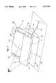
- FIG. 2is a schematic diagram showing a combination appearance of an image scanner and a preferred embodiment of a sheet feeder according to the present invention.
- FIG. 3is a partly enlarged schematic diagram illustratively showing the engagement of an image scanner with a sheet feeder according to the present invention.
- FIG. 2is a schematic diagram showing a combination appearance of an image scanner and a preferred embodiment of a sheet feeder according to the present invention.
- the sheet feeder 22is used with the image scanner 21 for transmitting a sheet object (not shown) to be scanned through a passage 24 between the image scanner 21 and the sheet feeder 22.
- the sheet feederhas a sloping plane or support side 221 extending between input end 230a of input zone 230 and output end 232a of output zone 232 detachably mounting thereon, extending transverse to the movement of the sheet object, the image scanner 21 and allowing the sheet object to be transmitted between the image scanner 21 and the sheet feeder 22 along the sloping plane 221 for assisting in monitoring the transmission situation of the sheet object.
- the sloping plane or support side 221is located on an opposite side of the sheet feeder from a base 238 of the sheet feeder and is oriented so that the sloping plane or sloping support side 221 faces upward and slopes relative to horizontal support surface 250 on which the base 238 is placed to support the sheet feeder. Also, it is convenient for the user to stand or sit on the same side without unnecessary movement for easily feeding and receiving the sheet object.
- the sheet feeder according to the present inventionfurther includes a plate 224 on the sloping plane 221 for supporting the sheet object to be scanned, and two adjusting boards 225 movably mounted on opposite transverse sides of the plate, and support side 221, along which the sheet object slides, for adjusting a distance therebetween according to the width of the sheet object to position the sheet object in place.
- the sloping plane or support side 221 along which the sheet object slidesextends from input end 230a of input zone to output end 232a of output zone 232, with output end 232a located adjacent horizontal support surface 250 on which the base portion 238 supports the sheet feeder.
- a part or portion 2211 of output zone 232 of the sloping plate 221 receiving the scanned sheet objectis preferably made concave curved at end 230a with end 230a unblocked or open for smoothly receiving the sheet object and sliding the sheet object onto support surface 250.
- the sheet objectWhen in use, the sheet object is placed on the plate 224 and near the entrance 241 of the passage 24 by one side thereof, and the two adjusting boards 225 are properly adjusted according to the width of the sheet object to assisting in the straight advance of the sheet object. Because the plate 224 is sloping, the sheet object will smoothly slide into the entrance 241 due to the gravity. The scanned sheet object then transmitted away from the image scanner 21 through the exit 242 of the passage 24 and falls in the part 2211 of the sloping plane 221. On the other hand, the power cable 212 of the image scanner 21 can be installed on the lateral of the scanner 21 so that it will not adversely influence the transmission of the sheet object.
- the slope of the plane 221should be evaluated according to the user's visual angle and the fictional force between the sheet object to be scanned and the sloping plane.
- the image scanner 21can be attached on the sloping plane 221 of the present sheet feeder 22 by way of screwing.
- the screwing manneris as shown in FIG. 3.
- the sheet feeder 22further includes a screwing disk 223 for assisting in the engagement of the conductive screw 222 with the conductive threaded hollow cylinder 211 by spining the screwing disk 223.
- the image scanner 21is fixed onto the sheet feeder 22 by snap-locking.
- the present inventionutilizes an improvement on a sheet feeder structure to make the sheet feeder more pragmatic.
Landscapes
- Engineering & Computer Science (AREA)
- Multimedia (AREA)
- Signal Processing (AREA)
- Facsimile Scanning Arrangements (AREA)
- Exposure Or Original Feeding In Electrophotography (AREA)
Abstract
Description
Claims (7)
Priority Applications (1)
| Application Number | Priority Date | Filing Date | Title |
|---|---|---|---|
| US08/498,539US5711516A (en) | 1995-07-05 | 1995-07-05 | Sheet feeder having sloping sheet support side for use with detachable image scanner |
Applications Claiming Priority (1)
| Application Number | Priority Date | Filing Date | Title |
|---|---|---|---|
| US08/498,539US5711516A (en) | 1995-07-05 | 1995-07-05 | Sheet feeder having sloping sheet support side for use with detachable image scanner |
Publications (1)
| Publication Number | Publication Date |
|---|---|
| US5711516Atrue US5711516A (en) | 1998-01-27 |
Family
ID=23981490
Family Applications (1)
| Application Number | Title | Priority Date | Filing Date |
|---|---|---|---|
| US08/498,539Expired - LifetimeUS5711516A (en) | 1995-07-05 | 1995-07-05 | Sheet feeder having sloping sheet support side for use with detachable image scanner |
Country Status (1)
| Country | Link |
|---|---|
| US (1) | US5711516A (en) |
Cited By (11)
| Publication number | Priority date | Publication date | Assignee | Title |
|---|---|---|---|---|
| US5973799A (en)* | 1997-07-30 | 1999-10-26 | Cyberscan Technology, Inc. | ID card image reader |
| US6037684A (en)* | 1999-04-28 | 2000-03-14 | Campbell Haufeld/Scott Fetzer Company | HVLP motor assembly |
| US6581834B2 (en)* | 2001-10-19 | 2003-06-24 | Primax Electronics, Ltd. | Image processing apparatus having scanner portion and removable card reader portion |
| US20050157143A1 (en)* | 2004-01-21 | 2005-07-21 | Silverbrook Research Pty Ltd. | Combination printer and image reader in L-shaped configuration |
| US20050259298A1 (en)* | 2004-05-18 | 2005-11-24 | Avision Inc. | Duplex scan method of detecting document size |
| US7133169B2 (en) | 1996-11-05 | 2006-11-07 | Yoshiki Tsuchiyama | Apparatus equipped with removable scanner unit |
| US20070057428A1 (en)* | 2005-09-14 | 2007-03-15 | Lite-On Technology Corporation | Paper feed tray with image scanning function and printer thereof |
| US20070102872A1 (en)* | 2005-11-10 | 2007-05-10 | Xerox Corporation | Automatic document sacanner with upright visible document images |
| US7379218B1 (en)* | 1996-11-05 | 2008-05-27 | Fujitsu Limited | Apparatus equipped with removable scanner unit |
| US8016646B1 (en)* | 2008-12-23 | 2011-09-13 | Bailey Kenneth L | Saw blade sharpening assembly |
| US8079683B2 (en) | 2004-01-21 | 2011-12-20 | Silverbrook Research Pty Ltd | Inkjet printer cradle with shaped recess for receiving a printer cartridge |
Citations (12)
| Publication number | Priority date | Publication date | Assignee | Title |
|---|---|---|---|---|
| US4298270A (en)* | 1979-02-02 | 1981-11-03 | Olympus Optical Company Limited | Electrographic apparatus |
| JPS5813064A (en)* | 1981-07-17 | 1983-01-25 | Matsushita Graphic Commun Syst Inc | Facsimile device |
| JPS6392565A (en)* | 1986-10-07 | 1988-04-23 | Canon Inc | Original reader |
| JPH02310217A (en)* | 1989-05-25 | 1990-12-26 | Canon Inc | Sheet tray |
| US4989237A (en)* | 1988-03-15 | 1991-01-29 | Sharp Kabushiki Kaisha | Image data transmission apparatus |
| JPH0416454A (en)* | 1990-05-09 | 1992-01-21 | Omron Corp | Document reset system for facsimile |
| US5103322A (en)* | 1990-05-14 | 1992-04-07 | Polaroid Corporation | Scanner with retractable roller feed |
| JPH0517048A (en)* | 1991-07-12 | 1993-01-26 | Canon Inc | Paper feeder |
| US5330173A (en)* | 1993-03-11 | 1994-07-19 | Wensink Gary L | Hand scanner apparatus |
| US5384624A (en)* | 1991-04-04 | 1995-01-24 | Canon Kabushiki Kaisha | Image forming apparatus with automatic control for drawing cassette therefrom |
| US5431389A (en)* | 1994-08-26 | 1995-07-11 | Wensink; Gary L. | Hand scanner support and paper guide apparatus |
| US5454555A (en)* | 1989-09-18 | 1995-10-03 | Canon Kabushiki Kaisha | Recording apparatus |
- 1995
- 1995-07-05USUS08/498,539patent/US5711516A/ennot_activeExpired - Lifetime
Patent Citations (12)
| Publication number | Priority date | Publication date | Assignee | Title |
|---|---|---|---|---|
| US4298270A (en)* | 1979-02-02 | 1981-11-03 | Olympus Optical Company Limited | Electrographic apparatus |
| JPS5813064A (en)* | 1981-07-17 | 1983-01-25 | Matsushita Graphic Commun Syst Inc | Facsimile device |
| JPS6392565A (en)* | 1986-10-07 | 1988-04-23 | Canon Inc | Original reader |
| US4989237A (en)* | 1988-03-15 | 1991-01-29 | Sharp Kabushiki Kaisha | Image data transmission apparatus |
| JPH02310217A (en)* | 1989-05-25 | 1990-12-26 | Canon Inc | Sheet tray |
| US5454555A (en)* | 1989-09-18 | 1995-10-03 | Canon Kabushiki Kaisha | Recording apparatus |
| JPH0416454A (en)* | 1990-05-09 | 1992-01-21 | Omron Corp | Document reset system for facsimile |
| US5103322A (en)* | 1990-05-14 | 1992-04-07 | Polaroid Corporation | Scanner with retractable roller feed |
| US5384624A (en)* | 1991-04-04 | 1995-01-24 | Canon Kabushiki Kaisha | Image forming apparatus with automatic control for drawing cassette therefrom |
| JPH0517048A (en)* | 1991-07-12 | 1993-01-26 | Canon Inc | Paper feeder |
| US5330173A (en)* | 1993-03-11 | 1994-07-19 | Wensink Gary L | Hand scanner apparatus |
| US5431389A (en)* | 1994-08-26 | 1995-07-11 | Wensink; Gary L. | Hand scanner support and paper guide apparatus |
Cited By (20)
| Publication number | Priority date | Publication date | Assignee | Title |
|---|---|---|---|---|
| US7379218B1 (en)* | 1996-11-05 | 2008-05-27 | Fujitsu Limited | Apparatus equipped with removable scanner unit |
| US7133169B2 (en) | 1996-11-05 | 2006-11-07 | Yoshiki Tsuchiyama | Apparatus equipped with removable scanner unit |
| US5973799A (en)* | 1997-07-30 | 1999-10-26 | Cyberscan Technology, Inc. | ID card image reader |
| US6037684A (en)* | 1999-04-28 | 2000-03-14 | Campbell Haufeld/Scott Fetzer Company | HVLP motor assembly |
| US6581834B2 (en)* | 2001-10-19 | 2003-06-24 | Primax Electronics, Ltd. | Image processing apparatus having scanner portion and removable card reader portion |
| US20080012890A1 (en)* | 2004-01-21 | 2008-01-17 | Silverbrook Research Pty Ltd | Inkjet printer unit utilizing image reading unit for printed media collection |
| US8079683B2 (en) | 2004-01-21 | 2011-12-20 | Silverbrook Research Pty Ltd | Inkjet printer cradle with shaped recess for receiving a printer cartridge |
| US7661812B2 (en) | 2004-01-21 | 2010-02-16 | Silverbrook Research Pty Ltd | Printer unit for assembly with image reader unit |
| US7513615B2 (en) | 2004-01-21 | 2009-04-07 | Silverbrook Research Pty Ltd | Inkjet printer unit utilizing image reading unit for printed media collection |
| US7152972B2 (en)* | 2004-01-21 | 2006-12-26 | Silverbrook Research Pty Ltd | Combination printer and image reader in L-shaped configuration |
| US8439497B2 (en) | 2004-01-21 | 2013-05-14 | Zamtec Ltd | Image processing apparatus with nested printer and scanner |
| US20090058893A1 (en)* | 2004-01-21 | 2009-03-05 | Silverbrook Research Pty Ltd | Printer unit for assembly with image reader unit |
| US20100134553A1 (en)* | 2004-01-21 | 2010-06-03 | Silverbrook Research Pty Ltd | Printer for nesting with image reader |
| US20050157143A1 (en)* | 2004-01-21 | 2005-07-21 | Silverbrook Research Pty Ltd. | Combination printer and image reader in L-shaped configuration |
| US8079700B2 (en) | 2004-01-21 | 2011-12-20 | Silverbrook Research Pty Ltd | Printer for nesting with image reader |
| US20050259298A1 (en)* | 2004-05-18 | 2005-11-24 | Avision Inc. | Duplex scan method of detecting document size |
| US20070057428A1 (en)* | 2005-09-14 | 2007-03-15 | Lite-On Technology Corporation | Paper feed tray with image scanning function and printer thereof |
| US20070102872A1 (en)* | 2005-11-10 | 2007-05-10 | Xerox Corporation | Automatic document sacanner with upright visible document images |
| US7828286B2 (en)* | 2005-11-10 | 2010-11-09 | Xerox Corporation | Automatic document scanner with upright visible document images |
| US8016646B1 (en)* | 2008-12-23 | 2011-09-13 | Bailey Kenneth L | Saw blade sharpening assembly |
Similar Documents
| Publication | Publication Date | Title |
|---|---|---|
| US5711516A (en) | Sheet feeder having sloping sheet support side for use with detachable image scanner | |
| US4437638A (en) | Arrangement for fastening a monitor to a text station | |
| US6915994B2 (en) | Arm apparatus for mounting electronic devices with cable management system | |
| US5700051A (en) | Information card mounted to a chair | |
| BE905932A (en) | LIFTING MACHINE FOR INVALID. | |
| FR2689188B1 (en) | DEVICE OPPOSING THE ADJUSTMENTS FOR AN ADJUSTMENT SCREW. | |
| US5116011A (en) | Accessory track to accommodate multiple accessories | |
| US5743499A (en) | Arm support for computer operator | |
| EP0926567A3 (en) | Mounting system for a removable media holder in a scanning apparatus | |
| USD349491S (en) | Handheld input device for computers | |
| GB2304642A (en) | A document support device for a keyboard | |
| US4570802A (en) | Printer stand | |
| US6307649B1 (en) | Mountable scanning device and computer monitor including same | |
| MY114045A (en) | Specialty media feed guide and sheet feeding apparatus using same | |
| IT1292692B1 (en) | PROCEDURE AND MACHINE FOR AUTOMATIC BENDING OF PROFILES AND SIMILAR. | |
| US4871273A (en) | Adjustable paper handler apparatus | |
| US5687943A (en) | Apparatus for supporting a video camera and cable above a work surface | |
| FR2713687B1 (en) | Device for supporting an over-roof, and corresponding cover-over-roof assembly. | |
| KR900014951A (en) | Paper Feeder of Copier | |
| KR920007821A (en) | Laser beam printer with feed cassette removed | |
| WO1988006856A1 (en) | Holder for sheets of paper | |
| FR2672645B1 (en) | DEVICE FOR FIXING AN ELEMENT IN AN ADJUSTABLE POSITION AT THE END OF A TUBE. | |
| KR20000014600U (en) | Monitor feeder | |
| FR2678704B1 (en) | DEVICE FOR SUPPORTING ELONGATE OBJECTS. | |
| GB2221616A (en) | Adjustable picture hanger |
Legal Events
| Date | Code | Title | Description |
|---|---|---|---|
| AS | Assignment | Owner name:PRIMAX ELECTRONICS LTD., CHINA Free format text:ASSIGNMENT OF ASSIGNORS INTEREST;ASSIGNOR:PAN, AMPERE;REEL/FRAME:007574/0600 Effective date:19950626 | |
| AS | Assignment | Owner name:SILICON VALLEY BANK, CALIFORNIA Free format text:SECURITY INTEREST;ASSIGNOR:STORM PRIMAX, INC.;REEL/FRAME:008013/0194 Effective date:19960516 | |
| AS | Assignment | Owner name:STORM TECHNOLOGY INC., CALIFORNIA Free format text:ASSIGNMENT OF ASSIGNORS INTEREST;ASSIGNOR:PRIMAX ELECTRONICS LTD.;REEL/FRAME:008496/0634 Effective date:19970423 | |
| STCF | Information on status: patent grant | Free format text:PATENTED CASE | |
| AS | Assignment | Owner name:SILICON VALLEY BANK, CALIFORNIA Free format text:AMENDMENT TO COLLATERAL ASSIGNMENT, PATENT MORTGAGE AND SECURITY AGREEMENT;ASSIGNOR:STORM TECHNOLOGY, INC.;REEL/FRAME:009360/0172 Effective date:19980713 | |
| CC | Certificate of correction | ||
| AS | Assignment | Owner name:SILITEK CORPORATION, TAIWAN Free format text:ASSIGNMENT OF ASSIGNORS INTEREST;ASSIGNOR:ROBERTSON, JEROME E. TRUSTEE IN BANKRUPTCY FOR STORM TECHNOLOGIES, INC.;REEL/FRAME:012059/0417 Effective date:19990927 | |
| AS | Assignment | Owner name:SILITEK CORPORATION, TAIWAN Free format text:ASSIGNMENT OF ASSIGNORS INTEREST;ASSIGNOR:STORM TECHNOLOGY INC.;REEL/FRAME:011648/0470 Effective date:19990927 | |
| FPAY | Fee payment | Year of fee payment:4 | |
| AS | Assignment | Owner name:LITE-ON TECHNOLOGY CORPORATION, TAIWAN Free format text:MERGER;ASSIGNOR:SILITEK CORPORATION;REEL/FRAME:014863/0499 Effective date:20021113 | |
| FPAY | Fee payment | Year of fee payment:8 | |
| FPAY | Fee payment | Year of fee payment:12 |