US5711313A - Discoverable earplug - Google Patents
Discoverable earplugDownload PDFInfo
- Publication number
- US5711313A US5711313AUS08/785,415US78541597AUS5711313AUS 5711313 AUS5711313 AUS 5711313AUS 78541597 AUS78541597 AUS 78541597AUS 5711313 AUS5711313 AUS 5711313A
- Authority
- US
- United States
- Prior art keywords
- earplug
- detectable
- insert
- fastener
- shaft
- Prior art date
- Legal status (The legal status is an assumption and is not a legal conclusion. Google has not performed a legal analysis and makes no representation as to the accuracy of the status listed.)
- Expired - Lifetime
Links
- 239000006260foamSubstances0.000claimsabstractdescription8
- 239000000463materialSubstances0.000claimsabstractdescription6
- 239000002184metalSubstances0.000claimsabstractdescription6
- 210000000613ear canalAnatomy0.000claimsdescription8
- 229920000642polymerPolymers0.000claimsdescription6
- 239000006261foam materialSubstances0.000claimsdescription5
- 239000004020conductorSubstances0.000claimsdescription2
- 238000000034methodMethods0.000claims3
- 239000002861polymer materialSubstances0.000claims2
- 238000000465mouldingMethods0.000claims1
- 238000012994industrial processingMethods0.000abstract1
- 239000004033plasticSubstances0.000description3
- 229920003023plasticPolymers0.000description3
- 238000010276constructionMethods0.000description2
- 238000001514detection methodMethods0.000description2
- 230000004048modificationEffects0.000description2
- 238000012986modificationMethods0.000description2
- 208000034809Product contaminationDiseases0.000description1
- 229910000831SteelInorganic materials0.000description1
- 239000000853adhesiveSubstances0.000description1
- 230000001070adhesive effectEffects0.000description1
- 230000008878couplingEffects0.000description1
- 238000010168coupling processMethods0.000description1
- 238000005859coupling reactionMethods0.000description1
- 229920006351engineering plasticPolymers0.000description1
- 238000009434installationMethods0.000description1
- 239000000696magnetic materialSubstances0.000description1
- 239000002984plastic foamSubstances0.000description1
- 238000004080punchingMethods0.000description1
- 238000011084recoveryMethods0.000description1
- 239000007787solidSubstances0.000description1
- 239000010959steelSubstances0.000description1
Images
Classifications
- A—HUMAN NECESSITIES
- A61—MEDICAL OR VETERINARY SCIENCE; HYGIENE
- A61F—FILTERS IMPLANTABLE INTO BLOOD VESSELS; PROSTHESES; DEVICES PROVIDING PATENCY TO, OR PREVENTING COLLAPSING OF, TUBULAR STRUCTURES OF THE BODY, e.g. STENTS; ORTHOPAEDIC, NURSING OR CONTRACEPTIVE DEVICES; FOMENTATION; TREATMENT OR PROTECTION OF EYES OR EARS; BANDAGES, DRESSINGS OR ABSORBENT PADS; FIRST-AID KITS
- A61F11/00—Methods or devices for treatment of the ears or hearing sense; Non-electric hearing aids; Methods or devices for enabling ear patients to achieve auditory perception through physiological senses other than hearing sense; Protective devices for the ears, carried on the body or in the hand
- A61F11/06—Protective devices for the ears
- A61F11/08—Protective devices for the ears internal, e.g. earplugs
- A61F11/12—External mounting means
Definitions
- Earplugsare worn by industrial workers to protect their hearing. However, when worn by workers in the food or pharmaceutical industry, there is danger of product contamination if an earplug should fall into the material being processed.
- Such industriesuse detectors for metallic and other objects, but such detectors usually cannot detect earplugs molded of foam plastic or other plastic or rubber.
- European patent publication 244,979 and U.S. Pat. 4,936,411show a metal object inserted into a deep hole or channel extending along the axis of a solid rubber or other polymer earplug. It can require substantial cost to insert the object and securely lock it in place, especially if the earplug is formed of foam material.
- a metal object or other detectable insertwhich could be very securely attached to earplugs, especially those of the compressible foam plastic type, and in a manner that enabled attachment at low cost, would be of value.
- a detectable earplugwhich can be constructed at low cost.
- the earplugincludes a molded earplug body having an axis extending in forward and rearward directions and having a forward portion that first enters a persons ear canal and having a rearward portion.
- the earplugalso includes a detectable insert that is attached to the body.
- the insertcomprises a fastener with a shaft extending through a lateral hole in the body between laterally opposite sides of the body.
- the fastenerincludes enlargements lying at laterally opposite sides of the body rearward portion.
- the bodyis preferably formed of a compressible resilient foam, with the body portion lying between the enlargements being compressed therebetween.
- an end portion of the cordcan be trapped between the fastener and the earplug body.
- the cordcan be wrapped about the shaft and trapped between a first of the enlargements and the body rearward portion that lies between the enlargements.
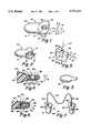
- FIG. 1is an isometric view of a detectable earplug of one embodiment of the present invention.
- FIG. 2is a side view of the earplug of FIG. 1, as taken along a lateral direction.
- FIG. 3is a side view of the earplug of FIG. 2, taken along a longitudinal direction.
- FIG. 4is an enlarged sectional view taken on line 4--4 of FIG. 2.
- FIG. 5is a partial isometric view of a detectable earplug constructed in accordance with another embodiment of the invention.
- FIG. 6is a view taken on line 6--6 of FIG. 5.
- FIG. 7is an isometric view of a detectable earplug assembly which includes two earplugs and a cord connecting them.
- FIG. 8is a view taken on line 8--8 of FIG. 7.
- FIG. 9is a sectional view taken on line 9--9 of FIG. 8, showing only the fastener and cord.
- FIG. 10is an exploded view showing one manner in which the fastener and cord of FIG. 8 can be assembled.
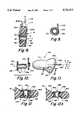
- FIG. 11is an isometric view of a detectable earplug of another embodiment of the invention.
- FIG. 12is a sectional view taken on line 12--12 of FIG. 11.
- FIG. 12Ais a sectional view similar to FIG. 12, but with another insert.
- FIG. 1illustrates a detectable earplug 10 which includes an earplug body 12 and a detectable insert 14 mounted on the body.
- the earplug bodyhas an axis 16 extending in forward and rearward directions F, R.
- the bodyhas a front portion 20 which is the portion that is initially inserted into a person's ear canal to block sound, and has a rearward portion 22, with the particular rearward portion shown being designed to lie outside the entrance to the ear canal.
- the earplug body 12is generally of the shape shown in U.S. Pat. No. Des. 329,897.
- the bodyis molded of a soft polymer (modulus of elasticity of less than 50,000 psi), that is, a polymer that can be significantly compressed and/or deflected by forces of several ounces typically applied by the walls of the ear canal to an earplug, and has a much lower modulus of elasticity than engineering plastics (whose modulus of elasticity is more than 100,000 psi).
- the particular body 12is formed of resilient plastic foam, such as slow recovery foam which is easily compressed and which takes about one minute to recover to near its original uncompressed shape.
- the earplughas a through hole 30 that extends in a lateral direction L which is perpendicular to the axis 16.
- the insertis in the form of a fastener such as an eyelet, which has a barrel or shaft 32 that projects through the hole 30 and which has flanges or enlargements 34, 36 at laterally opposite sides 40, 42 of the body rearward portion.
- the enlargements 34, 36are shown as being in the form of washers that completely surround the shaft.
- a region 44 of the body that lies between the enlargements 34, 36,is highly compressed, by more than 20% of its original thickness, and usually by at least about 50% of its original thickness.
- the insert 14formed by a shaft that passes completely through the earplug rearward portion in a direction perpendicular to the axis of the earplug, enables simple and secure mounting of the insert.
- a through holeis formed in the earplug.
- the eyelet (14)is projected through the hole, the eyelet having a flange or enlargement at only one end.
- the other end of the eyeletis deformed to form the second enlargement 36, with the deformation proceeding until the region 44 of the body between enlargements is highly compressed.
- the eyeletis a very low cost item, and its installation can be achieved at low cost.
- Applicantprefers to use an earplug body with longitudinally opposite sides 50, 52, which are longitudinally spaced in longitudinal direction M, by more than the width of the front portion 20 of the body. This provides side portions that can be easily grasped to withdraw the earplug.
- the longitudinal middle of the body rear portionhas a lateral width (in direction L, FIG. 4) which is much less than the longitudinal width of the front portion 20 of the body. The result is to provide a thin but wide rear portion that can be readily grasped, to pull out the earplug.
- FIG. 5illustrates the earplug body 12 with a different detectable insert 60 attached to the rear portion 22 of the body.
- the insert 60forms a fastener with a shaft 62 extending in a lateral direction L completely through a hole 64 in the body.
- the fastener formed by the insertincludes enlargements 66, 68 lying on lateral opposite sides 70, 72 of the body rearward portion, and with the body including a region 74 that is tightly squeezed between the enlargements.
- the enlargements 66, 68 of the particular insert shown,extend to the rear edge 76 of the body, where they are joined by an insert rear end 80.
- the shaft 62includes two shaft parts 82, 84 which lock together when the insert is installed on the body.
- FIGS. 7-10illustrate a pair of detectable earplugs 90, 92 of an earplug assembly 94 that includes a cord 96 having opposite end portions or ends 100, 102 that are securely fixed to the earplugs.
- a cordthat joins the earplugs, makes it less likely that one of the two earplugs will be dropped.
- Each of the earplugs such as 90includes an earplug body 12 and a detectable insert 14 which is securely fastened to the body. Applicant uses the insert 14 to securely hold a corresponding end 100 of the cord.
- FIGS. 8 and 9the cord end 100 is wrapped about the shaft 32 of the insert and is trapped between a compressed region 44 of the earplug body and an enlargement 34 of the insert that presses against the compressed body portion.
- Applicantprefers that the cord end 100 be wrapped more than 360°about the shaft, and with the cord having overlapping areas 102, 104 that are fastened together, as with adhesive.
- FIG. 10shows one example of the manner in which the cord end 100 can be installed on the insert.
- the insertis shown in its initial configuration 14A, wherein one of the enlargements at 36A has not yet been radially outwardly deformed.
- the cordis formed into the loop 110, and the loop is slid over the insert shaft 32 and against the already formed enlargement 34.
- a holeis formed in the rearward portion of the earplug body, and the insert 14A with the cord loop 110 installed thereon, is pressed through the hole. Then, the initial enlargement area at 36A is deformed radially outwardly (with respect to the shaft axis 112) until the enlargement assumes the shape shown at 36 in FIG. 8.
- the enlargement 34can be formed with its radially outer edge bent to assure that the cord is not weakened.
- the cord end 100can be securely coupled to the insert 14 in a number of ways, including wrapping the cord so it extends axially, or in the lateral direction L, between the opposite enlargements, as indicated at 100X. Another way is to thread the cord through a hole in the shaft 32 and to tie a knot or other enlargement at the extreme end of the cord.
- FIG. 8shows, in phantom lines, a cord at 114 that extends in a loop through the hollow shaft of the eyelet insert 14, with the cord tied to itself at 116.
- FIG. 5shows, in phantom lines, a cord at 117 that extends in a loop through the insert 60 and with the cord held to itself at 118.
- the hole 30 in the bodycan be formed by thrusting a sharp-pointed piercing tool through the body or by punching out a piece of material of the body. Applicant prefers to merely pierce the body, with a piercing tool whose cross section is in the shape of a cross.
- FIGS. 11 and 12illustrate another earplug 120 that includes an earplug body 12 of the same construction as in FIG. 1, and a detectable insert 122 and cord end 124.
- the insertis a rivet that is offset from the earplug body axis 126, and that extends primarily perpendicular to the axis through the body.
- the card end 124lies in a hole 130 that extends along the axis of the body, and is glued in place. This construction can be useful where tooling is already setup to install the cord as shown, and it is desired to add the detectable insert 122 for special applications.
- FIG. 12shows that the insert includes a shaft 132 with opposite flanges 134, 136. Caps 140, 142 are fastened around the flanges to give a more "finished"look. The caps also add metal for easier detection, and avoid edges on the enlargements 144, 146 formed by the flanges and caps, that can cut into the compressed region 150 of the body and allow the insert to pullout.
- FIG. 12Ashows a lower cost alternative, where the insert 150 includes an eyelet 152 and a washer 154. The eyelet is supplied with an enlargement 156 having a flat face 158 that presses against the earplug body 12. The washer 154 has a flat face 160, and is held down by a rolled-over eyelet flange 162 that has a concave lower face 164.
- Applicantprefers to use an insert merely formed of metal (or other conductive material) for detection by reason of its conductivity, or of a magnetic material such as steel which can be detected by its magnetic properties.
- metalor other conductive material
- magnetic materialsuch as steel which can be detected by its magnetic properties.
- the inventionprovides a detectable earplug which includes a molded earplug body and a detectable insert that is attached to the rear body, where the insert comprises a fastener with a shaft that projects through a hole extending primarily perpendicular to the axis of the earplug and having enlargements extending from the shaft and lying at opposite sides of the body.
- the lateral directioncould be the direction M of FIG. 1, wherein a longer insert would be used.
- the bodyis formed of resilient foam material
- the enlargementscan compress a region of the body lying between them, to provide a secure and low cost fastening of the insert to the resilient foam body.
- it is desired to attach an end portion of a cord to the earplugthis can be readily accomplished by coupling the cord to the insert.
Landscapes
- Health & Medical Sciences (AREA)
- Life Sciences & Earth Sciences (AREA)
- Biomedical Technology (AREA)
- Acoustics & Sound (AREA)
- Biophysics (AREA)
- Otolaryngology (AREA)
- Psychology (AREA)
- Engineering & Computer Science (AREA)
- Physics & Mathematics (AREA)
- Heart & Thoracic Surgery (AREA)
- Vascular Medicine (AREA)
- Animal Behavior & Ethology (AREA)
- General Health & Medical Sciences (AREA)
- Public Health (AREA)
- Veterinary Medicine (AREA)
- Soundproofing, Sound Blocking, And Sound Damping (AREA)
- Clamps And Clips (AREA)
- Insertion Pins And Rivets (AREA)
- Orthopedics, Nursing, And Contraception (AREA)
Abstract
Description
Claims (14)
Priority Applications (4)
| Application Number | Priority Date | Filing Date | Title |
|---|---|---|---|
| US08/785,415US5711313A (en) | 1997-01-23 | 1997-01-23 | Discoverable earplug |
| EP97309046AEP0855176B1 (en) | 1997-01-23 | 1997-11-11 | Discoverable earplug |
| DE69728514TDE69728514T2 (en) | 1997-01-23 | 1997-11-11 | Detectable earplugs |
| AU45251/97AAU695296B1 (en) | 1997-01-23 | 1997-11-17 | Discoverable earplug |
Applications Claiming Priority (1)
| Application Number | Priority Date | Filing Date | Title |
|---|---|---|---|
| US08/785,415US5711313A (en) | 1997-01-23 | 1997-01-23 | Discoverable earplug |
Publications (1)
| Publication Number | Publication Date |
|---|---|
| US5711313Atrue US5711313A (en) | 1998-01-27 |
Family
ID=25135457
Family Applications (1)
| Application Number | Title | Priority Date | Filing Date |
|---|---|---|---|
| US08/785,415Expired - LifetimeUS5711313A (en) | 1997-01-23 | 1997-01-23 | Discoverable earplug |
Country Status (4)
| Country | Link |
|---|---|
| US (1) | US5711313A (en) |
| EP (1) | EP0855176B1 (en) |
| AU (1) | AU695296B1 (en) |
| DE (1) | DE69728514T2 (en) |
Cited By (24)
| Publication number | Priority date | Publication date | Assignee | Title |
|---|---|---|---|---|
| WO2000040188A1 (en)* | 1999-01-07 | 2000-07-13 | Cabot Safety Intermediate Corporation | Detectable earplug and method of manufacture thereof |
| FR2842726A1 (en)* | 2002-07-25 | 2004-01-30 | Serge Schlee | Hygienic anti-noise ear plug comprises receptor and support base with opening integral with pipe having lugs taking spongy cover, pipe receiving interchangeable filter |
| US20040079579A1 (en)* | 2002-10-28 | 2004-04-29 | Barwacz Robert Franciszek | Corded hearing protective device and method of manufacturing the same |
| US20080314393A1 (en)* | 2007-06-22 | 2008-12-25 | Ricky Wayne Purcell | Self-conforming sound attenuation earplug |
| US20090250072A1 (en)* | 2008-04-03 | 2009-10-08 | Collins Timothy R | Magnetic Earplug |
| USD605171S1 (en)* | 2008-04-28 | 2009-12-01 | Koninklijke Philips Electronics N.V. | Headphone |
| US20100043806A1 (en)* | 2008-08-22 | 2010-02-25 | Steven Craig Gehling | Self-conforming sound attenuation earplug |
| US20120073583A1 (en)* | 2010-09-28 | 2012-03-29 | Moldex-Metric, Inc. | Corded earplugs |
| US20120103104A1 (en)* | 2010-10-27 | 2012-05-03 | Chevron U.S.A. Inc. | Testing device for stress corrosion cracking |
| US20120272974A1 (en)* | 2011-04-26 | 2012-11-01 | Moldex-Metric, Inc. | Corded earplug |
| US20140305733A1 (en)* | 2013-04-10 | 2014-10-16 | Howard S. Leight | Pull out earplug |
| USD733676S1 (en) | 2013-11-18 | 2015-07-07 | 3M Innovative Properties Company | Hearing device tether acoustic decoupling section |
| US9445177B2 (en) | 2013-11-18 | 2016-09-13 | 3M Innovative Properties Company | Hearing device tether with acoustic decoupling section |
| USD783003S1 (en)* | 2013-02-07 | 2017-04-04 | Decibullz Llc | Moldable earpiece |
| US9628889B2 (en) | 2012-02-08 | 2017-04-18 | Decibullz Llc | Moldable earpiece system |
| US10149038B2 (en) | 2017-01-20 | 2018-12-04 | Decibullz Llc | Earpiece intra-auricular support system |
| US10507599B2 (en) | 2017-04-07 | 2019-12-17 | Decibullz Llc | Moldable earpiece heating case |
| USD889754S1 (en) | 2017-09-01 | 2020-07-07 | 3M Innovative Properties Company | Hearing protector |
| US10728648B2 (en) | 2017-08-23 | 2020-07-28 | Decibullz Llc | Reconfigurable intra-auricular support |
| EP3730107A1 (en)* | 2019-04-26 | 2020-10-28 | Moldex-Metric AG & Co. KG | An ear plug for human ears, an ear plug system, a corded ear plug |
| USD925493S1 (en) | 2019-11-25 | 2021-07-20 | Decibullz Llc | Intra-auricular earbud support |
| US11076995B2 (en) | 2017-09-01 | 2021-08-03 | 3M Innovative Properties Company | Cold-drawn polyolefin copolymers cord for earplug |
| US11304851B2 (en) | 2017-09-01 | 2022-04-19 | 3M Innovative Properties Company | Push-to-fit earplug with tip cavity |
| US11937998B2 (en) | 2016-04-01 | 2024-03-26 | 3M Innovative Properties Company | Hearing protection device and method of forming same |
Families Citing this family (2)
| Publication number | Priority date | Publication date | Assignee | Title |
|---|---|---|---|---|
| EP1629807A1 (en)* | 2004-08-25 | 2006-03-01 | Phonak Ag | Hearing protection earplug, method for manufacturing the same and method for detecting an earplug |
| DE102005034733B4 (en)* | 2005-07-21 | 2007-10-25 | Drescher, Rüdiger | noise protector |
Citations (6)
| Publication number | Priority date | Publication date | Assignee | Title |
|---|---|---|---|---|
| US125339A (en)* | 1872-04-02 | Improvement in ear-muffs | ||
| US516135A (en)* | 1894-03-06 | Adalbert tpiamm | ||
| US758680A (en)* | 1903-11-18 | 1904-05-03 | Albert Edward C Otte | Ear-hood. |
| US955276A (en)* | 1909-03-22 | 1910-04-19 | John Lopizich | Ear-plug for bathers. |
| US4253452A (en)* | 1979-05-24 | 1981-03-03 | Specialty Composites Corporation | Ear plug assembly |
| US4936411A (en)* | 1988-08-19 | 1990-06-26 | Cabot Corporation | Detectable earplug |
Family Cites Families (6)
| Publication number | Priority date | Publication date | Assignee | Title |
|---|---|---|---|---|
| US329897A (en) | 1885-11-10 | Adolph geiss | ||
| GB8610455D0 (en)* | 1986-04-29 | 1986-06-04 | Safer Safety Ltd | Ear plugs |
| US4807612A (en)* | 1987-11-09 | 1989-02-28 | Industrial Research Products, Inc. | Passive ear protector |
| US5074375A (en)* | 1989-10-18 | 1991-12-24 | Grozil Richard S | Hearing protection system assembly |
| SE502365C2 (en)* | 1991-04-19 | 1995-10-09 | Bilsom Ab | Detectable hearing protection plug |
| US5249309A (en)* | 1992-09-17 | 1993-10-05 | Bilsom Ab | Ear defender |
- 1997
- 1997-01-23USUS08/785,415patent/US5711313A/ennot_activeExpired - Lifetime
- 1997-11-11EPEP97309046Apatent/EP0855176B1/ennot_activeExpired - Lifetime
- 1997-11-11DEDE69728514Tpatent/DE69728514T2/ennot_activeExpired - Lifetime
- 1997-11-17AUAU45251/97Apatent/AU695296B1/ennot_activeExpired
Patent Citations (6)
| Publication number | Priority date | Publication date | Assignee | Title |
|---|---|---|---|---|
| US125339A (en)* | 1872-04-02 | Improvement in ear-muffs | ||
| US516135A (en)* | 1894-03-06 | Adalbert tpiamm | ||
| US758680A (en)* | 1903-11-18 | 1904-05-03 | Albert Edward C Otte | Ear-hood. |
| US955276A (en)* | 1909-03-22 | 1910-04-19 | John Lopizich | Ear-plug for bathers. |
| US4253452A (en)* | 1979-05-24 | 1981-03-03 | Specialty Composites Corporation | Ear plug assembly |
| US4936411A (en)* | 1988-08-19 | 1990-06-26 | Cabot Corporation | Detectable earplug |
Cited By (51)
| Publication number | Priority date | Publication date | Assignee | Title |
|---|---|---|---|---|
| US6920956B1 (en) | 1999-01-07 | 2005-07-26 | Cabot Safety Intermediate Corporation | Detectable earplug and method of manufacture thereof |
| WO2000040188A1 (en)* | 1999-01-07 | 2000-07-13 | Cabot Safety Intermediate Corporation | Detectable earplug and method of manufacture thereof |
| FR2842726A1 (en)* | 2002-07-25 | 2004-01-30 | Serge Schlee | Hygienic anti-noise ear plug comprises receptor and support base with opening integral with pipe having lugs taking spongy cover, pipe receiving interchangeable filter |
| US9155661B2 (en) | 2002-10-28 | 2015-10-13 | 3M Innovative Properties Company | Corded hearing protective device and method of manufacturing the same |
| WO2004039296A3 (en)* | 2002-10-28 | 2004-11-04 | Cabot Safety Intermediate Corp | Corded hearing protective device and method of manufacturing the same |
| WO2004039296A2 (en) | 2002-10-28 | 2004-05-13 | Cabot Safety Intermediate Corporation | Corded hearing protective device and method of manufacturing the same |
| RU2348389C2 (en)* | 2002-10-28 | 2009-03-10 | Кэбот Сейфти Интермидиейт Корпорейшн | Cord hearing prostration device and related production method |
| AU2003287090B2 (en)* | 2002-10-28 | 2009-05-07 | 3M Innovative Properties Company | Corded hearing protective device and method of manufacturing the same |
| US8708091B2 (en)* | 2002-10-28 | 2014-04-29 | 3M Innovative Properties Company | Corded hearing protective device and method of manufacturing the same |
| US20040079579A1 (en)* | 2002-10-28 | 2004-04-29 | Barwacz Robert Franciszek | Corded hearing protective device and method of manufacturing the same |
| US20080314393A1 (en)* | 2007-06-22 | 2008-12-25 | Ricky Wayne Purcell | Self-conforming sound attenuation earplug |
| US7984716B2 (en) | 2007-06-22 | 2011-07-26 | Kimberly-Clark Worldwide Inc. | Self-conforming sound attenuation earplug |
| US20090250072A1 (en)* | 2008-04-03 | 2009-10-08 | Collins Timothy R | Magnetic Earplug |
| US8079366B2 (en) | 2008-04-03 | 2011-12-20 | Collins Timothy R | Magnetic earplug |
| USD605171S1 (en)* | 2008-04-28 | 2009-12-01 | Koninklijke Philips Electronics N.V. | Headphone |
| US20100043806A1 (en)* | 2008-08-22 | 2010-02-25 | Steven Craig Gehling | Self-conforming sound attenuation earplug |
| US8113207B2 (en) | 2008-08-22 | 2012-02-14 | Kimberly-Clark Worldwide, Inc. | Self-conforming sound attenuation earplug |
| US20120073583A1 (en)* | 2010-09-28 | 2012-03-29 | Moldex-Metric, Inc. | Corded earplugs |
| US8671948B2 (en)* | 2010-09-28 | 2014-03-18 | Moldex-Metric, Inc. | Corded earplugs |
| US8375803B2 (en)* | 2010-10-27 | 2013-02-19 | Chevron U.S.A. Inc. | Testing device for stress corrosion cracking |
| US20120103104A1 (en)* | 2010-10-27 | 2012-05-03 | Chevron U.S.A. Inc. | Testing device for stress corrosion cracking |
| US10441469B2 (en)* | 2011-04-26 | 2019-10-15 | Moldex-Metric, Inc. | Corded earplug |
| US20140246029A1 (en)* | 2011-04-26 | 2014-09-04 | Moldex-Metric, Inc. | Corded earplug |
| US20120272974A1 (en)* | 2011-04-26 | 2012-11-01 | Moldex-Metric, Inc. | Corded earplug |
| US11750961B2 (en) | 2012-02-08 | 2023-09-05 | Decibullz Llc | Moldable earpiece system |
| US9628889B2 (en) | 2012-02-08 | 2017-04-18 | Decibullz Llc | Moldable earpiece system |
| US9769555B2 (en) | 2012-02-08 | 2017-09-19 | Decibullz Llc | Moldable earpiece system |
| US11303986B2 (en) | 2012-02-08 | 2022-04-12 | Decibullz Llc | Moldable earpiece system |
| US10091571B2 (en) | 2012-02-08 | 2018-10-02 | Decibullz Llc | Moldable earpiece system |
| US10779073B2 (en) | 2012-02-08 | 2020-09-15 | Decibullz Llc | Moldable earpiece system |
| USD783003S1 (en)* | 2013-02-07 | 2017-04-04 | Decibullz Llc | Moldable earpiece |
| US20140305733A1 (en)* | 2013-04-10 | 2014-10-16 | Howard S. Leight | Pull out earplug |
| US9763832B2 (en)* | 2013-04-10 | 2017-09-19 | Howard S. Leight | Pull out earplug |
| USD733676S1 (en) | 2013-11-18 | 2015-07-07 | 3M Innovative Properties Company | Hearing device tether acoustic decoupling section |
| US9445177B2 (en) | 2013-11-18 | 2016-09-13 | 3M Innovative Properties Company | Hearing device tether with acoustic decoupling section |
| USD802555S1 (en) | 2013-11-18 | 2017-11-14 | 3M Innovative Properties Company | Hearing device tether acoustic decoupling section |
| US11937998B2 (en) | 2016-04-01 | 2024-03-26 | 3M Innovative Properties Company | Hearing protection device and method of forming same |
| US11381902B2 (en) | 2017-01-20 | 2022-07-05 | Decibullz Llc | Earpiece intra-auricular support system |
| US10462552B2 (en) | 2017-01-20 | 2019-10-29 | Decibullz Llc | Earpiece intra-auricular support system |
| US10149038B2 (en) | 2017-01-20 | 2018-12-04 | Decibullz Llc | Earpiece intra-auricular support system |
| US10856065B2 (en) | 2017-01-20 | 2020-12-01 | Decibullz Llc | Earpiece intra-auricular support system |
| US11606639B2 (en) | 2017-01-20 | 2023-03-14 | Decibullz Llc | Earpiece intra-auricular support system |
| US10507599B2 (en) | 2017-04-07 | 2019-12-17 | Decibullz Llc | Moldable earpiece heating case |
| US10728648B2 (en) | 2017-08-23 | 2020-07-28 | Decibullz Llc | Reconfigurable intra-auricular support |
| US11490189B2 (en) | 2017-08-23 | 2022-11-01 | Decibullz Llc | Reconfigurable intra-auricular support |
| USD895901S1 (en) | 2017-09-01 | 2020-09-08 | 3M Innovative Properties Company | Hearing protector |
| US11304851B2 (en) | 2017-09-01 | 2022-04-19 | 3M Innovative Properties Company | Push-to-fit earplug with tip cavity |
| US11076995B2 (en) | 2017-09-01 | 2021-08-03 | 3M Innovative Properties Company | Cold-drawn polyolefin copolymers cord for earplug |
| USD889754S1 (en) | 2017-09-01 | 2020-07-07 | 3M Innovative Properties Company | Hearing protector |
| EP3730107A1 (en)* | 2019-04-26 | 2020-10-28 | Moldex-Metric AG & Co. KG | An ear plug for human ears, an ear plug system, a corded ear plug |
| USD925493S1 (en) | 2019-11-25 | 2021-07-20 | Decibullz Llc | Intra-auricular earbud support |
Also Published As
| Publication number | Publication date |
|---|---|
| DE69728514D1 (en) | 2004-05-13 |
| DE69728514T2 (en) | 2005-02-24 |
| AU695296B1 (en) | 1998-08-13 |
| EP0855176A3 (en) | 1998-11-11 |
| EP0855176A2 (en) | 1998-07-29 |
| EP0855176B1 (en) | 2004-04-07 |
Similar Documents
| Publication | Publication Date | Title |
|---|---|---|
| US5711313A (en) | Discoverable earplug | |
| US5727566A (en) | Trackable earplug | |
| EP0761984A1 (en) | Snap tab for fastening components together | |
| EP1020131A3 (en) | Binding band | |
| EP1258945A3 (en) | Line-shaped antenna | |
| US6385877B1 (en) | Livestock tag locking system | |
| EP1223354A3 (en) | Fastener | |
| US4907425A (en) | Jewelry clutch | |
| US4237588A (en) | Clamp for pipes or the like | |
| EP1136707A2 (en) | Holding element for fastening components to a carrier provided with an opening | |
| AU2000236503A1 (en) | Fastening-type security seal | |
| EP0786241B1 (en) | Trackable earplug | |
| EP1388301B1 (en) | Buckle | |
| EP1293952A3 (en) | Article identification and security tag | |
| KR200183274Y1 (en) | Combination type button being used for clothing, bag, shoes etc. | |
| US20040016086A1 (en) | System and method for snap stud | |
| CA1211904A (en) | Fastener for a garment | |
| US5745964A (en) | Push-button closure part | |
| JPH0465250B2 (en) | ||
| CN109878853A (en) | An anti-counterfeiting buckle and anti-counterfeiting packaging | |
| CA2117971C (en) | Cord fastening device | |
| KR102775469B1 (en) | spring snap button | |
| US6719338B2 (en) | Dummy trim with an improved resistance to pull | |
| US5901421A (en) | Pull tab of the zipper head | |
| US6882277B2 (en) | Electronic article surveillance marker assembly |
Legal Events
| Date | Code | Title | Description |
|---|---|---|---|
| AS | Assignment | Owner name:HOWARD S. LEIGHT AND ASSOCIATES, INC., CALIFORNIA Free format text:ASSIGNMENT OF ASSIGNORS INTEREST;ASSIGNOR:FLEMING, THOMAS WALTER;REEL/FRAME:008404/0361 Effective date:19970122 | |
| STCF | Information on status: patent grant | Free format text:PATENTED CASE | |
| FEPP | Fee payment procedure | Free format text:PAT HLDR NO LONGER CLAIMS SMALL ENT STAT AS SMALL BUSINESS (ORIGINAL EVENT CODE: LSM2); ENTITY STATUS OF PATENT OWNER: LARGE ENTITY | |
| FPAY | Fee payment | Year of fee payment:4 | |
| AS | Assignment | Owner name:CHASE MANHATTAN INTERNATIONAL LIMITED, AS SECURITY Free format text:SECURITY INTEREST;ASSIGNOR:BACOU USA SAFETY, INC.;REEL/FRAME:012295/0242 Effective date:20010904 | |
| AS | Assignment | Owner name:HOWARD LEIGHT INDUSTRIES, LLC, CALIFORNIA Free format text:CORRECTIVE ASSIGNMENT TO CORRECT THE 5771313 PREVIOUSLY RECORDED ON REEL 015530 FRAME 0125;ASSIGNOR:HOWARD S. LEIGHT AND ASSOCIATES, INC.;REEL/FRAME:015810/0516 Effective date:20040616 | |
| FPAY | Fee payment | Year of fee payment:8 | |
| AS | Assignment | Owner name:SPERIAN HEARING PROTECTION, LLC (DELAWARE LIMITED Free format text:CHANGE OF NAME;ASSIGNOR:HOWARD LEIGHT INDUSTRIES, LLC;REEL/FRAME:019910/0067 Effective date:20070823 | |
| FPAY | Fee payment | Year of fee payment:12 | |
| AS | Assignment | Owner name:SPERIAN PROTECTION AMERICAS, INC., A DELAWARE CORP Free format text:MERGER AND CHANGE OF NAME;ASSIGNORS:SPERIAN HEARING PROTECTION, LLC, A DELAWARE LIMITED LIABILITY COMPANY;SPERIAN PROTECTION AMERICAS, INC., A DELAWARE CORPORATION;REEL/FRAME:033908/0687 Effective date:20131220 Owner name:SPERIAN PROTECTION AMERICAS, INC., A DELAWARE CORPORATION, RHODE ISLAND Free format text:MERGER AND CHANGE OF NAME;ASSIGNORS:SPERIAN HEARING PROTECTION, LLC, A DELAWARE LIMITED LIABILITY COMPANY;SPERIAN PROTECTION AMERICAS, INC., A DELAWARE CORPORATION;REEL/FRAME:033908/0687 Effective date:20131220 | |
| AS | Assignment | Owner name:HONEYWELL SAFETY PRODUCTS USA, INC., RHODE ISLAND Free format text:CHANGE OF NAME;ASSIGNOR:SPERIAN PROTECTION AMERICAS, INC;REEL/FRAME:033948/0966 Effective date:20140101 |