US5709685A - Positionable clip for provisionally capturing a component on a spinal rod - Google Patents
Positionable clip for provisionally capturing a component on a spinal rodDownload PDFInfo
- Publication number
- US5709685A US5709685AUS08/651,967US65196796AUS5709685AUS 5709685 AUS5709685 AUS 5709685AUS 65196796 AUS65196796 AUS 65196796AUS 5709685 AUS5709685 AUS 5709685A
- Authority
- US
- United States
- Prior art keywords
- rod
- arms
- pair
- bar
- component
- Prior art date
- Legal status (The legal status is an assumption and is not a legal conclusion. Google has not performed a legal analysis and makes no representation as to the accuracy of the status listed.)
- Expired - Lifetime
Links
- 239000012858resilient materialSubstances0.000claimsdescription7
- 239000000463materialSubstances0.000claimsdescription5
- 230000000994depressogenic effectEffects0.000claimsdescription2
- 238000002513implantationMethods0.000description8
- 238000001356surgical procedureMethods0.000description8
- 238000012795verificationMethods0.000description8
- 210000000988bone and boneAnatomy0.000description7
- 239000007943implantSubstances0.000description2
- 238000000034methodMethods0.000description2
- 238000012986modificationMethods0.000description2
- 230000004048modificationEffects0.000description2
- 229920004943Delrin®Polymers0.000description1
- 230000004075alterationEffects0.000description1
- 230000000712assemblyEffects0.000description1
- 238000000429assemblyMethods0.000description1
- 238000005452bendingMethods0.000description1
- 239000000560biocompatible materialSubstances0.000description1
- 230000006835compressionEffects0.000description1
- 238000007906compressionMethods0.000description1
- 230000001010compromised effectEffects0.000description1
- 230000000881depressing effectEffects0.000description1
- 230000000694effectsEffects0.000description1
- 230000004927fusionEffects0.000description1
- 230000014759maintenance of locationEffects0.000description1
- 230000013011matingEffects0.000description1
- 230000001737promoting effectEffects0.000description1
- 230000000717retained effectEffects0.000description1
- 230000000087stabilizing effectEffects0.000description1
- 229910001220stainless steelInorganic materials0.000description1
- 239000010935stainless steelSubstances0.000description1
Images


Classifications
- A—HUMAN NECESSITIES
- A61—MEDICAL OR VETERINARY SCIENCE; HYGIENE
- A61B—DIAGNOSIS; SURGERY; IDENTIFICATION
- A61B17/00—Surgical instruments, devices or methods
- A61B17/56—Surgical instruments or methods for treatment of bones or joints; Devices specially adapted therefor
- A61B17/58—Surgical instruments or methods for treatment of bones or joints; Devices specially adapted therefor for osteosynthesis, e.g. bone plates, screws or setting implements
- A61B17/68—Internal fixation devices, including fasteners and spinal fixators, even if a part thereof projects from the skin
- A61B17/70—Spinal positioners or stabilisers, e.g. stabilisers comprising fluid filler in an implant
- A61B17/7001—Screws or hooks combined with longitudinal elements which do not contact vertebrae
- A61B17/7035—Screws or hooks, wherein a rod-clamping part and a bone-anchoring part can pivot relative to each other
- A61B17/7037—Screws or hooks, wherein a rod-clamping part and a bone-anchoring part can pivot relative to each other wherein pivoting is blocked when the rod is clamped
- A—HUMAN NECESSITIES
- A61—MEDICAL OR VETERINARY SCIENCE; HYGIENE
- A61B—DIAGNOSIS; SURGERY; IDENTIFICATION
- A61B17/00—Surgical instruments, devices or methods
- A61B17/56—Surgical instruments or methods for treatment of bones or joints; Devices specially adapted therefor
- A61B17/58—Surgical instruments or methods for treatment of bones or joints; Devices specially adapted therefor for osteosynthesis, e.g. bone plates, screws or setting implements
- A61B17/68—Internal fixation devices, including fasteners and spinal fixators, even if a part thereof projects from the skin
- A61B17/70—Spinal positioners or stabilisers, e.g. stabilisers comprising fluid filler in an implant
- A61B17/7001—Screws or hooks combined with longitudinal elements which do not contact vertebrae
- A61B17/7035—Screws or hooks, wherein a rod-clamping part and a bone-anchoring part can pivot relative to each other
- A61B17/7038—Screws or hooks, wherein a rod-clamping part and a bone-anchoring part can pivot relative to each other to a different extent in different directions, e.g. within one plane only
- A—HUMAN NECESSITIES
- A61—MEDICAL OR VETERINARY SCIENCE; HYGIENE
- A61B—DIAGNOSIS; SURGERY; IDENTIFICATION
- A61B17/00—Surgical instruments, devices or methods
- A61B17/56—Surgical instruments or methods for treatment of bones or joints; Devices specially adapted therefor
- A61B17/58—Surgical instruments or methods for treatment of bones or joints; Devices specially adapted therefor for osteosynthesis, e.g. bone plates, screws or setting implements
- A61B17/68—Internal fixation devices, including fasteners and spinal fixators, even if a part thereof projects from the skin
- A61B17/70—Spinal positioners or stabilisers, e.g. stabilisers comprising fluid filler in an implant
- A61B17/7001—Screws or hooks combined with longitudinal elements which do not contact vertebrae
- A61B17/7041—Screws or hooks combined with longitudinal elements which do not contact vertebrae with single longitudinal rod offset laterally from single row of screws or hooks
- Y—GENERAL TAGGING OF NEW TECHNOLOGICAL DEVELOPMENTS; GENERAL TAGGING OF CROSS-SECTIONAL TECHNOLOGIES SPANNING OVER SEVERAL SECTIONS OF THE IPC; TECHNICAL SUBJECTS COVERED BY FORMER USPC CROSS-REFERENCE ART COLLECTIONS [XRACs] AND DIGESTS
- Y10—TECHNICAL SUBJECTS COVERED BY FORMER USPC
- Y10T—TECHNICAL SUBJECTS COVERED BY FORMER US CLASSIFICATION
- Y10T24/00—Buckles, buttons, clasps, etc.
- Y10T24/34—Combined diverse multipart fasteners
- Y10T24/3427—Clasp
- Y10T24/3439—Plural clasps
- Y10T24/344—Resilient type clasp
Definitions
- This inventionrelates to orthopaedic implants, and particularly implant systems utilizing spinal rods spanning the length of the spine. More specifically, the invention concerns devices for provisionally positioning components, such as clamps, on a spinal rod during an implantation procedure.
- a bendable rodis disposed longitudinally adjacent the vertebral column and is fixed to various vertebrae along the length of the spine by way of a number of fixation elements.
- fixation elementscan be provided which are configured to engage specific portions of the vertebra.
- one such fixation elementis a spinal compression/distraction hook.
- spinal hookis used to anchor the rod by engaging the laminae of a vertebra.
- spinal screwwhich includes cancellous threads for engagement within the vertebral bone.
- Rod-based spinal fixation systemscan be external or internal.
- An example of an internal rod-type spinal fixation systemis the TSRH® Spinal System sold by Danek Medical, Inc.
- a spinal hooksuch as hook 10 shown in FIG. 1
- the spinal hook 10includes a hook portion 11 configured to engage a portion of a vertebra, and an integral head portion 12.
- the head portion in this particular hook of the TSRH® Spinal Systemincludes a pair of posts 15 disposed apart from each other to form a U-shape yoke defining a slot 16 therebetween.
- the opposite faces 18 of the top portion 12define a pair of coaxial grooves 19 that are configured to receive a portion of the spinal rod R.
- the eyebolt assembly 20includes an eyebolt body 21 defining an opening 22 through which the spinal rod R is received.
- a threaded post 23extends from the body 21 for engagement with a threaded nut 24.
- the eyebolt body 21is "pre-threaded" onto the spinal rod R so that the rod extends through the aperture 22 of a number of eyebolts 21 corresponding to each of the vertebral levels to be instrumented.
- the spinal hook 10is disposed with its yoke posts 15 straddling the body 21 of the eyebolt assembly 20, with the threaded post 23 and a portion of the body 21 extending through the slot 16.
- One surface 18 of the spinal hookis disposed against the rod R, specifically with the rod situated within a pair of coaxial grooves 19.
- the nut 24can then be threaded onto the post 23 and against a surface 18 to clamp the spinal hook to the spinal rod in accordance with the "three-point shear clamp" aspect of the TSRH®System.
- eyebolt bodies 21are threaded onto a spinal rod R prior to implantation into the patient's body. These eyebolts 21 are not fixed to the rod at that time since it is necessary to precisely locate and fix them only after the rod R has been placed within the body and the positions of the corresponding spinal hooks or screws have been determined.
- the eyeboltsmust have some capability of sliding along the rod to match the position of various vertebral fixation elements that may already be implanted in the spine.
- a bone screwmay already be threaded into a vertebral body which may require some adjustment of the position of an eyebolt to engage the bone screw.
- many pre-planned positions for spinal hooksnecessitate that the hooks are already situated in the appropriate vertebral level before the spinal rod R is implanted. It is therefore frequently necessary for the position of the eyebolt body along the spinal rod to be varied to mate with the appropriate vertebral fixation element.
- Some prior systemsincorporate set screws on the clamps or other components disposed on the spinal rod. While these set screws are very adequate to fix the components on the rod after they are suitably positioned in the body, they do not lend themselves to simply temporarily snugging the component on the rod during handling prior to implantation.
- One prior systemthe Cotrel-Dubousset (CD) instrumentation, uses a blocker which is essentially a cylindrical element having a set screw in it. The cylindrical element is engaged with the component to be fixed onto the rod as a primary means for fixing the component to the rod. The set screw on the blocker can be used to provisionally position the cylindrical blocker on the spinal rod prior to final tightening.
- a discussion of this aspect of the CD Systemis found in U.S. Pat. No. 4,641,636 to Dr. Yves Paul Cotrel.
- a suturethrough the opening 22 in the eyebolt body 21.
- the suturecan be strung along several eyebolt assemblies 20 disposed along the length of the spinal rod R.
- the sutureis sufficiently thick to provide some frictional contact between the rod and the opening of the eyebolt to provisionally retain the eyebolt on the rod under more delicate handling circumstances.
- the sutureis not capable of providing sufficient gripping force to hold the eyebolt on the spinal rod under more rigorous handling during implantation.
- Another approachhas been to apply bone wax to the components to hold them onto the spinal rod.
- One disadvantage of this approachis that once the position of the component has been shifted on the spinal rod the provisional retention power of the bone wax is compromised.
- the concepts of the '315 Patentare not readily adaptable to other types of connectors or components engaged to a spinal rod, since the provisional clamping elements disclosed in the '315 Patent are only operable from within the eyebolt itself.
- the device shown in this prior patentgenerally requires that the provisional clamping element be retained within the construct after the system has been implanted within the patient.
- the present inventioncontemplates several embodiments of a positionable clip that is removably engageable about a component disposed on an elongated rod.
- the provisional clips of the present inventionprovisionally capture a component at a position on the rod while allowing the position to be varied at any point during the surgical procedure.
- the provisional clipsgrip the elongated rod with enough force to prevent the clip and the captured component from freely sliding along the rod during manipulation of the rod.
- the positionable clipcomprises a pair of clamping members, each including a pair of arms arranged to contact the elongated rod on opposite sides thereof.
- Each of said clamping membersincludes means for biasing the pair of arms together to provide a gripping force on the rod when the rod is disposed between the pair of arms.
- the clipalso comprises a bar connecting the pair of clamping members in spaced apart relation, with a length between the pair of clamping members sufficient to capture a component engaged on the elongated rod between the clamping members.
- the means for biasing the arms togetherincludes the pair of arms of each of the clamping members being formed of a resilient material.
- the resilient materialallows the pair of arms to resiliently deflect between a first position in which the arms are gripping the rod and a second position in which the arms are disposed apart sufficient for the rod to pass between the arms.
- the means for biasing the arms togetherincludes a resilient hinge between the pair of arms and the bar. In this specific embodiment, the hinge is resiliently openable to move the arms between the rod gripping position and the rod release position.
- the pair of arms of each of the pair of clamping membersdefines a clamping surface directed toward the rod.
- the clamping surfaceis configured to substantially conform to the outer surface of the rod.
- the rod engaging surface of the armsis partially cylindrical with substantially the same diameter as the spinal rod.
- the positionable clipincludes a lever arm attached to the bar opposite the pair of clamping members.
- the lever armis operable to remove the pair of clamping members from the rod when the rod is disposed between the pair of arms of the clamping members.
- the lever armis configured so that force applied to the lever arm creates a bending moment to disengage the arms of the clamping members from the spinal rod.
- the positionable clip of the present inventionalso contemplates means to disengage the clip from the spinal rod by operation of the component captured on the rod by the clip.
- the pair of arms of each of the clamping memberseach includes a pressure surface defined at the free end of the arms.
- the clipis engaged about a clamp disposed on the rod. As the clamp is tightened onto the rod, a surface of the clamp pushes against the pressure surface of the clamping arms of the positionable clip.
- the pressure surfaceis disposed on the bar between the clamping members and facing away from the bar. A force applied to the bar pressure surface causes the clamping surface of each of the arms to slide around the rod to deflect the pair of arms apart against the means for biasing.
- the positionable clipis formed or a radiolucent material, most preferably a plastic.
- verification of the position of the clip within the patientis desirable.
- a radio-opaque verification pinis disposed within the bar portion of the clip. This verification pin can be verified by A-P radiograph, thereby providing an indication of the position of the clip on the spinal rod.
- the present inventionalso contemplates another embodiment of the positionable clip that comprises a single clamping member including a pair of arms arranged to contact the elongated rod on opposite sides thereof, and means for biasing the pair of arms together to provide a gripping force on the rod when the rod is engaged between the pair of arms.
- This clipincludes a bar connected to the clamping member and having a length extending substantially parallel to the rod when the rod is engaged between the pair of arms.
- the barincludes a surface directed toward rod when the rod is engaged between the arms, which surface is configured to contact the component to capture the component in a position on the rod.
- the baris resiliently biased toward the rod when the rod is engaged between the pair of arms, so that the bar applies a clamping force against the component.
- the means for biasing the arms of the clamping memberincludes a resilient hinge connected between the pair of arms, and the clamping member further includes a pair of tabs extending from a corresponding one of the pair of arms. The tabs arranged relative to the resilient hinge to deflect the hinge when the tabs are depressed toward each other, whereby the pair of arms are disengaged from the rod.
- a positionable clipcomprises a bar having a length between first and second ends, the length sized to span a length of the component along the elongated rod when the component is disposed thereon.
- the clipfurther comprises a pair of upper arms, one each connected to the bar at a respective one of the first and second ends, and each defining a clamping surface directed toward the rod when the positionable clip is capturing a component on the rod.
- the clipcomprises a lower arm connected to the bar between the first and second ends, the lower arm defining a lower clamping surface directed toward the component when the component is disposed on the elongated rod. Biasing means are provided for biasing the pair of upper arms towards the lower arm to provide a gripping force on the elongated rod engaged therebetween.
- the clipcan include a lever arm connected to the bar and operable against the biasing means to disengage the upper arms and the lower arm from the elongated rod.
- the clamping surface of each of the pair of upper armsis sized to contact at least a third of the circumference of the elongated rod, and most preferably about half way around the rod circumference.
- One object of the present inventionis to provide a device that can temporarily retain or capture a component on a spinal rod during manipulation and implantation of the rod in a human patient. Another object is achieved by features of the invention that allow the device to hold its position on the rod and to be moved to a new position as necessary during the surgical procedure.
- Another object of the inventionis to provide a device that need not remain within the patient once the spinal fixation assembly is finally implanted.
- a further objectis embodied in aspects of the invention that allow the device to be disengaged from the spinal rod by operation of the component to be captured on the rod.
- FIG. 1is a perspective view of a spinal hook and rod construct of the prior art.
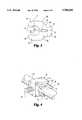
- FIG. 2is a perspective view of a positionable clip according to one embodiment of the present invention.
- FIG. 3is an end elevational view of the positionable clip shown in FIG. 2.
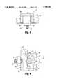
- FIG. 4is a perspective view of a rod having an eyebolt disposed thereon with the positionable clip of FIGS. 2,3 engaged about the eyebolt on the rod.
- FIG. 5is a top elevational view of the construct shown in FIG. 4.
- FIG. 6is a side elevational view of the construct shown in FIGS. 4 and 5 with the addition of the head of a spinal hook engaged to the eyebolt and spinal rod, in which the positionable clip is shown partially disengaged from the spinal rod.
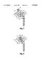
- FIG. 7is a side elevational view of a further construct for a top-tightening variable angle screw, shown with the positionable clip, as shown in FIGS. 2,3, engaged to the spinal rod.
- FIG. 8is a side elevational view of the construct shown in FIG. 7 with the positionable clip partially disengaged from the spinal rod as the set screw is tightened into the top-tightening assembly.
- FIG. 9is a perspective view of the top-tightening variable angle screw construct shown fully tightened after which the positionable clip is disengaged from the spinal rod.
- FIG. 10is a top elevational view of a further embodiment of the positionable clip of the present invention.
- FIG. 11is a side elevational view of the additional embodiment of the positionable clip shown in FIG. 10.
- FIG. 12is a side elevational view of a positionable clip of a third embodiment of the present invention.
- FIG. 13is a top elevational view of the positionable clip shown in FIG. 12.
- FIG. 14is a top perspective view of a positionable clip in accordance with a further embodiment of the present invention.
- FIG. 15shows a positionable clip according to that shown in FIG. 14 engaged on a spinal rod and capturing a component onto the rod.
- the present inventionconcerns a positionable clip that is engageable about a component disposed on an elongated spinal rod.
- This positionable clipprovisionally captures the component at a given position on the rod to help maintain the orientation of the components as the rod is manipulated prior to and during implantation in a human patient.
- the positionable clipis slidable to different positions on the rod as necessary to reposition the components disposed on the rod, while still maintaining an adequate clamping force on the rod to hold the component at the new position.
- the clipscan be readily disengaged from the spinal rod and removed from the surgical site. Most preferably, the clips of this invention can be at least partially disengaged from the spinal rod by operation of the captured component itself.
- a positionable clip 30is shown in FIGS. 2,3 that comprises a pair of clamping members 31.
- Each of the clamping membersincludes a pair of arms 33 defining a clamping surface 34.
- the clamping surfaceis arranged to engage the spinal rod when the positionable clip 30 is clamped onto the rod.
- the clamping surfaces 34are partially cylindrical to correspond to the outer cylindrical surface of the elongated spinal rod.
- the positionable clip 30includes a biasing means 35 which is configured to bias the arms 33 toward each other.
- This biasing means 35permits the arms to provide a clamping force on the rod to hold the clip 30 on the rod as the rod is manipulated and implanted within the patient.
- the biasing meansprovides only as much clamping force through the arms 33 as is necessary to keep the positionable clip 30 and the rod component that it captures from freely sliding up and down the spinal rod.
- the clamping force generated by the biasing means 35is also preferably sufficient to hold the position of the clip and its captured component during even the harshest manipulations of the spinal rod during the surgical procedure.
- the biasing meanspreferably does not provide so much clamping force on the rod through the arms 33 that the clip 30 cannot be easily slid along the rod to reposition the clip and its captured component.
- the biasing means 35while biasing the arms 33 together, is also preferably readily counteracted to permit spreading of the arms 33 to disengage the positionable clip 30 from the spinal rod.
- the biasing means 35constitutes the arms 33 being formed of a resilient material that can be deflected or deformed as the rod is slid outwardly along the clamping surfaces 34.
- the biasing means 35can include resilient arms 33 that can be urged apart by an outward movement of the spinal rod away from the clamping surfaces 34.
- the biasing means 35includes a hinge portion 36 integral with each of the arms 33.
- the hinge portionsare separated by hinge slot 37, which slot opens and closes as the arms 33 are pushed outward away from each other or together toward each other.
- the positionable clip 30 shown in FIGS. 2,3also includes a bar 38 spanning between and connecting the two clamping members 31.
- the bar 38 and the clamping members 31define a receiving space 39 therebetween which is sized to receive a particular component engaged to a spinal rod.
- the positionable clip 30is shown mounted on a spinal rod R.
- An eyebolt 20, which is identical to the eyebolt depicted in FIG. 1,is disposed on the rod R in the receiving space 39 of the positionable clip 30.
- the eyebolt 20is situated between the arms 33 of the clamping members 31 and is bordered on one side by the bar 38.
- the bar 38includes a bar pressure surface 40 which is in contact with the eyebolt body 21.
- the positionable clip 30is shown capturing an eyebolt body 21 on the rod R. It is understood that the eyebolt body 21 would normally freely slide along the longitudinal length of the rod R. However, the positionable clip 30 is engaged to the rod by way of the clamping force generated by the arms 33 and their biasing means 35.
- the arms 33provide a sufficient gripping force to resist movement of the eyebolt body 21 along the rod, even under the most severe manipulations of the spinal rod R.
- the clamping surface 34 engaging the outer cylindrical surface of the rod Ris capable of sliding along the rod R without damaging the rod. The arms 33 can then provide the same clamping force at the new location of the eyebolt body 21. This feature allows ready adjustment of the position of the eyebolt 20 at any point during the manipulation and implantation of the spinal rod R.
- these positionable clips 30can be engaged about various components disposed along a spinal rod R prior to implantation.
- several eyeboltssuch as the eyebolt 20, would be located on the spinal rod.
- the eyebolt 20could be used to engage a spinal hook, such as hook 10 shown in FIG. 1.
- the head portion 12 of the hook 10can be disposed about the eyebolt body 21.
- the nut 24is then threaded along the threaded post 23 to press the head 12 of the hook against the spinal rod R.
- the arms 33include an arm pressure surface 44 at their free end 45.
- the surface 18 of the spinal hookpushes against the arm pressure surface 44 of each of the arms 33.
- This pushing forceis in the direction of the arrow C shown at the left of FIG. 6.
- the arms 33are forced to ride along the outer surface of the spinal rod R, against the force of the biasing means 35 to thereby pivot the arms 33 in the direction of the arrows A.
- this pivoting movement designated by the arrows A of the arms 33serves to open the hinge slot 37 so that the space between the free ends 45 of the arms increases enough to allow the spinal rod R to pass between the arms.
- the location of the arm pressure surface 48, or more particularly the length of the arms 33is calibrated so that when the spinal hook 10 is fully tightened between the nut 24 and the rod R, the free ends 45 of the arms 33 are still in contact with the spinal rod.
- these endscontact the spinal rod at nearly diametrically opposite positions on the rod so that a simple pulling force applied to the positionable clip 30 will allow ready removal of the clip.
- the length of the arms 33 and the orientation of the arm pressure surfaces 44can be configured so that when the nut 24 is fully tightened down onto the hook 10 and rod R, the free ends 45 of the arms 33 slide easily off of the rod R.
- the positionable clip 30can be used with a different component engaged to a spinal rod R.
- one such componentcan be a clamp assembly 50, as shown in FIGS. 7-9, constituting part of a top-tightening variable angle screw assembly.
- the clamp assembly 50is used to engage a variable angle washer 59 and variable angle screw 58 to the spinal rod R.
- This particular system engaged to the spinal rod Ris described more fully in U.S. Pat. No, 5,282,801, issued on Feb. 1, 1994 to Mike Sherman entitled "Top-Tightening Clamp Assembly for a Spinal Fixation System".
- the disclosure of this '801 Patentis incorporated herein as it pertains to the structure and operation of the clamp assembly 50 and the components 58 and 59.
- the clamp assemblyincludes a clamp body 51 which defines a rod opening 52 through which the spinal rod R passes.
- a set screw bore 53passes through the clamp body 51 to intersect the rod opening 52.
- the body 51also includes a back surface 54 against which the bar 38 of the positionable clip 30 contacts.
- a set screw 55is threaded into the set screw bore 53 so that its tip 56 contacts the spinal rod R.
- the clamp assembly 50further includes a T-bar 57 which provides a surface against which the variable angle screw 58 is clamped.
- the positionable clip 30is depicted clamped about the body 51 of the clamp assembly 50.
- the clamping surface 34 of the arms 33is clamped onto the outer surface of the spinal rod R with sufficient pressure to hold the clamp body 51 in its position on the spinal rod R.
- the set screw 55is driven into the bore 53 in the direction of the arrow B.
- the tip 56pushes on the spinal rod R to force it in the direction of the arrow C.
- the spinal rod Ris moved in the direction C, it bears against the washer 59, which presses the variable angle bone screw 58 against the T-bar 57.
- the clamp body 51is, in effect, moving in the opposite direction by virtue of the driving force B applied by the set screw 55. More specifically, the back surface 54 of the clamp body 51 is pushed against the bar pressure surface 40 of the positionable clip 30. As the set screw 55 is fully tightened into the set screw bore 53, the back surface 54 continues to push against the bar pressure surface 40 of the positionable clip 30 which forces the free ends 45 of the arms 33 to move apart in the direction of the arrows A, as shown in FIG. 8.
- the movement of the clamp body 51 in relation to the length of the arms 33 and the location of the free ends 45is calibrated so that the free ends 45 remain in contact with the spinal rod R but on substantially diametrically opposite points on the rod so that the clip 30 can be easily plucked off of the rod.
- this length of the arms relative to the movement of the clamp body 51can be calibrated so that the free ends 45 of the arms 33 fall clear of the rod as the rod passes through the enlarged opening between the arms 33.
- the clamp assembly 50firmly affixes the bone screw 58 through the spinal rod R while the clamp assembly 30 is free of the spinal rod R, as shown in FIG. 9.
- the clipis formed of a radio-opaque plastic, such as DELRIN®.
- a radio-opaque verification pin 48may be inserted into a bore defined in the bar 38, as depicted in FIGS. 7-9.
- the position of the verification pin 48, and consequently the clip 30,can be ascertained from an A-P radiograph. Verification of the verification pin from a lateral view may be difficult due to the presence of the spinal rod R, unless the verification pin is formed of a material having a noticeably different opacity than the spinal rod R.
- the positionable clip 30is formed of a resilient and readily deflectable plastic that is capable of being restored to its original configuration without fracture or failure. Since the positionable clip 30 is not intended to remain within the patient, it need not be formed of a biocompatible material. In addition, the clip may be formed of a sterilizable material for reuse, or of a cheaper material for disposal after use.
- the clipis sized to engage a 1/4 inch stainless steel spinal rod.
- the arms and hinge portions 36extend a dimension of approximately 0.312 inches from the bar.
- the barhas a length of approximately 0.5 inches to accommodate a component such as the clamp assembly 50 shown in FIGS. 7-9.
- the clamping surfaces 34 of each of the arms of the positionable clipis circular and defined at a diameter of preferably 0.235 inches.
- the bar 38has a width of 0.20 inches and the hinge slot 37 of the biasing means 35 has a width of 0.035 inches.
- a positionable clip 60includes a pair of rod engaging arms 61 situated at the opposite ends of a bar 64.
- the armsare disposed apart a sufficient distance to capture either a clamp body 51 of a clamp assembly 50, or capture the washer 59 of the assembly 50, as shown in FIG. 10.
- the rod engaging arms 61define a rod clamp surface 62.
- the arms 61do not have an equivalent arm facing them on an opposite side of the spinal rod R.
- the rod clamp surface 62 of the arms 61is calibrated to extend in contact with at least 1/3 of the circumference of the spinal rod R.
- the arms 61include an arm extension 63 which extends the rod clamp surface 62 to contact about half of the circumference of the rod R.
- the bar 64can include a lower arm 65 projecting therefrom.
- the lower arm 65includes a body clamp surface 66 that is configured to engage the body 51 of the clamp assembly 50.
- the lower arm 65terminates in an arm extension 67 that is configured to wrap around a portion of the clamp body 51.
- the lower arm 65can include a second arm extension 68 that turns away from the clamp body, so that the lower arm 65 operates in the form of a spring to press the body clamp surface 66 against the clamp body 51.
- the positionable clip 60can also include a lever arm 69 projecting from the bar 64.
- the lever armcan be used to manually disengage the positionable clip 60 from the spinal rod R by exerting a moment force on the lever arm directed away from the upper arms 61.
- a moment force designated by the arrow labeled M in FIG. 11can be applied to the end of the lever arm 69, which force is reacted by pressure from the lower arm body clamp surface 66 against the clamp body 51.
- the body clamp surface 66 of the lower arm 65acts as a fulcrum to disengage the upper arms 61 from around the spinal rod R.
- the rod clamp surfaces 62slide around the outer circumference of the rod to open the arms 61 and disengage them from the rod.
- the positionable clip 60can be disengaged from the rod R in the same manner as the embodiment and application shown in FIGS. 7-9.
- the set screw 55As the set screw 55 is tightened into the clamp body 51, it pushes the rod R toward the washer 59. At the same time, the back surface of the clamp body 51 pushes back against the body clamp surface 66 of the lower arm 65. As the set screw 55 is further tightened into the clamp body, the rod R gradually disengages from the upper arms 61, permitting removal of the positionable clip 60.
- a positionable clip 70includes a pair of clamping members 71, each formed by a pair of opposing arms 73.
- the armsdefine clamping surfaces 74 which are configured to engage a spinal rod, in the manner of positionable clip 30 shown in FIGS. 2-3.
- the clip 70includes biasing means 75 which can be of the same type as the biasing means 35 in the previous embodiment.
- the positionable clip 70also includes a bar 78 to which ends the arms 73 are attached.
- the bar 78 and the clamping member 71define a receiving space 79 for capturing a component at a position on a spinal rod.
- the bar 78also includes a bar pressure surface 80 which acts in the same manner as bar pressure surface 40 of the positionable clip 30.
- the clip 70includes a lever arm 82 extending from the bar 78. This lever arm can be moved longitudinally in the direction of the arrow L to disengage the one set of arms 73 from the spinal rod, to ultimately disengage the entire clip from the rod.
- a positionable clip 90in a further embodiment of the invention shown in FIGS. 14 and 15, includes a clamping member 91 defined by a pair of opposed arms 93.
- the armsform a clamping surface 94 which is configured to engage a spinal rod R therebetween.
- the clip 90also includes a resilient hinge 95 formed between the two arms 92.
- the hingealso includes a pair of opening tabs 96 and 97, each of which are integral with a corresponding one of the arms 93. As shown in FIGS. 14 and 15, the opening tabs project away from the arms on opposite sides of the resilient hinge 95.
- the arms 93can be moved apart by depressing the two tabs 96 and 97 toward each other, thereby flexing the resilient hinge 95.
- the positionable clip 90further includes a bar 98 extending from the clamping member 91.
- the positionable clipincludes but a single bar and a single clamping member 91, so that the clip does not fully capture the component, such as component 50 in FIG. 15, on the spinal rod.
- the bar 98includes a contact surface 99 which is configured for a frictional engagement with the component 50.
- the bar 98can be formed of a resilient material to maintain a constant pressure on the component 50 to prevent it from sliding along the length of the spinal rod R.
Landscapes
- Health & Medical Sciences (AREA)
- Orthopedic Medicine & Surgery (AREA)
- Life Sciences & Earth Sciences (AREA)
- Neurology (AREA)
- Surgery (AREA)
- Heart & Thoracic Surgery (AREA)
- Engineering & Computer Science (AREA)
- Biomedical Technology (AREA)
- Nuclear Medicine, Radiotherapy & Molecular Imaging (AREA)
- Medical Informatics (AREA)
- Molecular Biology (AREA)
- Animal Behavior & Ethology (AREA)
- General Health & Medical Sciences (AREA)
- Public Health (AREA)
- Veterinary Medicine (AREA)
- Surgical Instruments (AREA)
Abstract
Description
This invention relates to orthopaedic implants, and particularly implant systems utilizing spinal rods spanning the length of the spine. More specifically, the invention concerns devices for provisionally positioning components, such as clamps, on a spinal rod during an implantation procedure.
Several techniques and systems have been developed for correcting and stabilizing spinal curves and for facilitating spinal fusion. In one type of system, a bendable rod is disposed longitudinally adjacent the vertebral column and is fixed to various vertebrae along the length of the spine by way of a number of fixation elements. A variety of fixation elements can be provided which are configured to engage specific portions of the vertebra. For instance, one such fixation element is a spinal compression/distraction hook. One type of spinal hook is used to anchor the rod by engaging the laminae of a vertebra. Another type of fixation element is a spinal screw, which includes cancellous threads for engagement within the vertebral bone.
Rod-based spinal fixation systems can be external or internal. An example of an internal rod-type spinal fixation system is the TSRH® Spinal System sold by Danek Medical, Inc. In this system, a spinal hook, such ashook 10 shown in FIG. 1, is engaged to an elongated fixation rod R by way of aneyebolt assembly 20. Thespinal hook 10 includes ahook portion 11 configured to engage a portion of a vertebra, and anintegral head portion 12. The head portion in this particular hook of the TSRH® Spinal System includes a pair ofposts 15 disposed apart from each other to form a U-shape yoke defining aslot 16 therebetween. Theopposite faces 18 of thetop portion 12 define a pair ofcoaxial grooves 19 that are configured to receive a portion of the spinal rod R.
Theeyebolt assembly 20 includes aneyebolt body 21 defining an opening 22 through which the spinal rod R is received. A threadedpost 23 extends from thebody 21 for engagement with a threadednut 24. In accordance with a use of the TSRH® Spinal System, theeyebolt body 21 is "pre-threaded" onto the spinal rod R so that the rod extends through theaperture 22 of a number ofeyebolts 21 corresponding to each of the vertebral levels to be instrumented.
As depicted in FIG. 1, thespinal hook 10 is disposed with itsyoke posts 15 straddling thebody 21 of theeyebolt assembly 20, with the threadedpost 23 and a portion of thebody 21 extending through theslot 16. Onesurface 18 of the spinal hook is disposed against the rod R, specifically with the rod situated within a pair ofcoaxial grooves 19. Thenut 24 can then be threaded onto thepost 23 and against asurface 18 to clamp the spinal hook to the spinal rod in accordance with the "three-point shear clamp" aspect of the TSRH®System.
In a surgical procedure involving the TSRH® System, and particularly theeyebolt assembly 20 as depicted in FIG. 1,several eyebolt bodies 21 are threaded onto a spinal rod R prior to implantation into the patient's body. Theseeyebolts 21 are not fixed to the rod at that time since it is necessary to precisely locate and fix them only after the rod R has been placed within the body and the positions of the corresponding spinal hooks or screws have been determined. One difficulty posed by this type of arrangement, namely having a plurality ofeyebolt bodies 21 loosely mounted on the spinal rod, is that these eyebolts can slide up and down along the rod and even fall off before the rod is placed within the patient. On the other hand, the eyebolts must have some capability of sliding along the rod to match the position of various vertebral fixation elements that may already be implanted in the spine. For example, a bone screw may already be threaded into a vertebral body which may require some adjustment of the position of an eyebolt to engage the bone screw. Likewise, many pre-planned positions for spinal hooks necessitate that the hooks are already situated in the appropriate vertebral level before the spinal rod R is implanted. It is therefore frequently necessary for the position of the eyebolt body along the spinal rod to be varied to mate with the appropriate vertebral fixation element.
Some prior systems incorporate set screws on the clamps or other components disposed on the spinal rod. While these set screws are very adequate to fix the components on the rod after they are suitably positioned in the body, they do not lend themselves to simply temporarily snugging the component on the rod during handling prior to implantation. One prior system, the Cotrel-Dubousset (CD) instrumentation, uses a blocker which is essentially a cylindrical element having a set screw in it. The cylindrical element is engaged with the component to be fixed onto the rod as a primary means for fixing the component to the rod. The set screw on the blocker can be used to provisionally position the cylindrical blocker on the spinal rod prior to final tightening. A discussion of this aspect of the CD System is found in U.S. Pat. No. 4,641,636 to Dr. Yves Paul Cotrel.
In practice, some surgeons have been known to string a suture through the opening 22 in theeyebolt body 21. The suture can be strung alongseveral eyebolt assemblies 20 disposed along the length of the spinal rod R. The suture is sufficiently thick to provide some frictional contact between the rod and the opening of the eyebolt to provisionally retain the eyebolt on the rod under more delicate handling circumstances. However, the suture is not capable of providing sufficient gripping force to hold the eyebolt on the spinal rod under more rigorous handling during implantation.
Another approach has been to apply bone wax to the components to hold them onto the spinal rod. One disadvantage of this approach is that once the position of the component has been shifted on the spinal rod the provisional retention power of the bone wax is compromised.
Another approach is disclosed in U.S. Pat. No, 5,403,315 to Richard Ashman. This patent discloses a positionable spinal fixation device which is implemented in the eyebolt assembly itself. As discussed more fully in the '315 Patent, which disclosure is incorporate herein by reference, one embodiment uses a set screw extending through the threaded post of the eyebolt, such as threadedpost 23 in FIG. 1 of the present application. This '315 Patent discusses additional embodiments that rely upon the eyebolt itself for both provisional and final clamping onto the rod. One difficulty with the positionable device disclosed in the '315 Patent is that it requires a more complicated eyebolt, instead of the use of an eyebolt of the type shown in FIG. 1. In addition, the concepts of the '315 Patent are not readily adaptable to other types of connectors or components engaged to a spinal rod, since the provisional clamping elements disclosed in the '315 Patent are only operable from within the eyebolt itself. Finally, the device shown in this prior patent generally requires that the provisional clamping element be retained within the construct after the system has been implanted within the patient.
There remains a need in the art of spinal surgery for a means for provisionally positioning a component on an elongated rod that resists movement of that component until it is finally attached to the rod. In addition, there is a need for such a device that can be used with virtually any type of component engaged on the spinal rod, and that can be readily removed.
In view of the need for provisional positioning of components during spinal surgery, the present invention contemplates several embodiments of a positionable clip that is removably engageable about a component disposed on an elongated rod. The provisional clips of the present invention provisionally capture a component at a position on the rod while allowing the position to be varied at any point during the surgical procedure. The provisional clips grip the elongated rod with enough force to prevent the clip and the captured component from freely sliding along the rod during manipulation of the rod.
In one embodiment, the positionable clip comprises a pair of clamping members, each including a pair of arms arranged to contact the elongated rod on opposite sides thereof. Each of said clamping members includes means for biasing the pair of arms together to provide a gripping force on the rod when the rod is disposed between the pair of arms. The clip also comprises a bar connecting the pair of clamping members in spaced apart relation, with a length between the pair of clamping members sufficient to capture a component engaged on the elongated rod between the clamping members.
In one specific embodiment, the means for biasing the arms together includes the pair of arms of each of the clamping members being formed of a resilient material. The resilient material allows the pair of arms to resiliently deflect between a first position in which the arms are gripping the rod and a second position in which the arms are disposed apart sufficient for the rod to pass between the arms. In another specific embodiment, the means for biasing the arms together includes a resilient hinge between the pair of arms and the bar. In this specific embodiment, the hinge is resiliently openable to move the arms between the rod gripping position and the rod release position.
In this preferred embodiment, the pair of arms of each of the pair of clamping members defines a clamping surface directed toward the rod. The clamping surface is configured to substantially conform to the outer surface of the rod. In the case of a cylindrical spinal rod, the rod engaging surface of the arms is partially cylindrical with substantially the same diameter as the spinal rod.
In a further aspect of the invention, the positionable clip includes a lever arm attached to the bar opposite the pair of clamping members. The lever arm is operable to remove the pair of clamping members from the rod when the rod is disposed between the pair of arms of the clamping members. In one specific embodiment, the lever arm is configured so that force applied to the lever arm creates a bending moment to disengage the arms of the clamping members from the spinal rod.
The positionable clip of the present invention also contemplates means to disengage the clip from the spinal rod by operation of the component captured on the rod by the clip. In one embodiment, the pair of arms of each of the clamping members each includes a pressure surface defined at the free end of the arms. When a force is applied to the pressure surface of each of the arms, the free ends of the arms and the clamping surface slide around the rod to deflect the pair of arms apart against the means for biasing. In one use of the inventive clip, the clip is engaged about a clamp disposed on the rod. As the clamp is tightened onto the rod, a surface of the clamp pushes against the pressure surface of the clamping arms of the positionable clip.
In an alternative specific embodiment, the pressure surface is disposed on the bar between the clamping members and facing away from the bar. A force applied to the bar pressure surface causes the clamping surface of each of the arms to slide around the rod to deflect the pair of arms apart against the means for biasing.
Preferably, the positionable clip is formed or a radiolucent material, most preferably a plastic. In some instances, verification of the position of the clip within the patient is desirable. In another specific aspect of the invention, a radio-opaque verification pin is disposed within the bar portion of the clip. This verification pin can be verified by A-P radiograph, thereby providing an indication of the position of the clip on the spinal rod.
The present invention also contemplates another embodiment of the positionable clip that comprises a single clamping member including a pair of arms arranged to contact the elongated rod on opposite sides thereof, and means for biasing the pair of arms together to provide a gripping force on the rod when the rod is engaged between the pair of arms. This clip includes a bar connected to the clamping member and having a length extending substantially parallel to the rod when the rod is engaged between the pair of arms. The bar includes a surface directed toward rod when the rod is engaged between the arms, which surface is configured to contact the component to capture the component in a position on the rod. In one aspect of this embodiment of the positionable clip, the bar is resiliently biased toward the rod when the rod is engaged between the pair of arms, so that the bar applies a clamping force against the component.
In a further feature of this embodiment, the means for biasing the arms of the clamping member includes a resilient hinge connected between the pair of arms, and the clamping member further includes a pair of tabs extending from a corresponding one of the pair of arms. The tabs arranged relative to the resilient hinge to deflect the hinge when the tabs are depressed toward each other, whereby the pair of arms are disengaged from the rod.
In yet another embodiment of the invention, a positionable clip comprises a bar having a length between first and second ends, the length sized to span a length of the component along the elongated rod when the component is disposed thereon. The clip further comprises a pair of upper arms, one each connected to the bar at a respective one of the first and second ends, and each defining a clamping surface directed toward the rod when the positionable clip is capturing a component on the rod. In one aspect of this embodiment, the clip comprises a lower arm connected to the bar between the first and second ends, the lower arm defining a lower clamping surface directed toward the component when the component is disposed on the elongated rod. Biasing means are provided for biasing the pair of upper arms towards the lower arm to provide a gripping force on the elongated rod engaged therebetween.
In one specific feature of this embodiment, the clip can include a lever arm connected to the bar and operable against the biasing means to disengage the upper arms and the lower arm from the elongated rod. In a further specific aspect, the clamping surface of each of the pair of upper arms is sized to contact at least a third of the circumference of the elongated rod, and most preferably about half way around the rod circumference.
One object of the present invention is to provide a device that can temporarily retain or capture a component on a spinal rod during manipulation and implantation of the rod in a human patient. Another object is achieved by features of the invention that allow the device to hold its position on the rod and to be moved to a new position as necessary during the surgical procedure.
Another object of the invention is to provide a device that need not remain within the patient once the spinal fixation assembly is finally implanted. A further object is embodied in aspects of the invention that allow the device to be disengaged from the spinal rod by operation of the component to be captured on the rod.
Each of these objects are addressed by the present invention and manifest themselves as important benefits to surgeons in the field of spinal surgery. These benefits include the capability to provisionally fix the position of a component on a spinal rod during even the most rigorous manipulation of the rod; the ability to readily adjust the position of the component as required to allow mating of the rod-borne component with vertebral fixation elements; and the capability of removing the device once the spinal rod and fixation system are finally positioned and implanted within the patient. Other objects and benefits of the present invention can be readily discerned from the following written description of the invention together with the accompanying figures.
FIG. 1 is a perspective view of a spinal hook and rod construct of the prior art.
FIG. 2 is a perspective view of a positionable clip according to one embodiment of the present invention.
FIG. 3 is an end elevational view of the positionable clip shown in FIG. 2.
FIG. 4 is a perspective view of a rod having an eyebolt disposed thereon with the positionable clip of FIGS. 2,3 engaged about the eyebolt on the rod.
FIG. 5 is a top elevational view of the construct shown in FIG. 4.
FIG. 6 is a side elevational view of the construct shown in FIGS. 4 and 5 with the addition of the head of a spinal hook engaged to the eyebolt and spinal rod, in which the positionable clip is shown partially disengaged from the spinal rod.
FIG. 7 is a side elevational view of a further construct for a top-tightening variable angle screw, shown with the positionable clip, as shown in FIGS. 2,3, engaged to the spinal rod.
FIG. 8 is a side elevational view of the construct shown in FIG. 7 with the positionable clip partially disengaged from the spinal rod as the set screw is tightened into the top-tightening assembly.
FIG. 9 is a perspective view of the top-tightening variable angle screw construct shown fully tightened after which the positionable clip is disengaged from the spinal rod.
FIG. 10 is a top elevational view of a further embodiment of the positionable clip of the present invention.
FIG. 11 is a side elevational view of the additional embodiment of the positionable clip shown in FIG. 10.
FIG. 12 is a side elevational view of a positionable clip of a third embodiment of the present invention.
FIG. 13 is a top elevational view of the positionable clip shown in FIG. 12.
FIG. 14 is a top perspective view of a positionable clip in accordance with a further embodiment of the present invention.
FIG. 15 shows a positionable clip according to that shown in FIG. 14 engaged on a spinal rod and capturing a component onto the rod.
For the purposes of promoting an understanding of the principles of the invention, reference will now be made to the embodiment illustrated in the drawings and specific language will be used to describe the same. It will nevertheless be understood that no limitation of the scope of the invention is thereby intended, such alterations and further modifications in the illustrated device, and such further applications of the principles of the invention as illustrated therein being contemplated as would normally occur to one skilled in the art to which the invention relates.
The present invention concerns a positionable clip that is engageable about a component disposed on an elongated spinal rod. This positionable clip provisionally captures the component at a given position on the rod to help maintain the orientation of the components as the rod is manipulated prior to and during implantation in a human patient. In addition, the positionable clip is slidable to different positions on the rod as necessary to reposition the components disposed on the rod, while still maintaining an adequate clamping force on the rod to hold the component at the new position. In a further feature of the positionable clips according to the present invention, the clips can be readily disengaged from the spinal rod and removed from the surgical site. Most preferably, the clips of this invention can be at least partially disengaged from the spinal rod by operation of the captured component itself.
In accordance with a first embodiment of the present invention, apositionable clip 30 is shown in FIGS. 2,3 that comprises a pair of clampingmembers 31. Each of the clamping members includes a pair ofarms 33 defining a clampingsurface 34. The clamping surface is arranged to engage the spinal rod when thepositionable clip 30 is clamped onto the rod. Preferably, the clamping surfaces 34 are partially cylindrical to correspond to the outer cylindrical surface of the elongated spinal rod.
Thepositionable clip 30 includes a biasing means 35 which is configured to bias thearms 33 toward each other. This biasing means 35 permits the arms to provide a clamping force on the rod to hold theclip 30 on the rod as the rod is manipulated and implanted within the patient. Preferably, the biasing means provides only as much clamping force through thearms 33 as is necessary to keep thepositionable clip 30 and the rod component that it captures from freely sliding up and down the spinal rod. The clamping force generated by the biasing means 35 is also preferably sufficient to hold the position of the clip and its captured component during even the harshest manipulations of the spinal rod during the surgical procedure. On the other hand, the biasing means preferably does not provide so much clamping force on the rod through thearms 33 that theclip 30 cannot be easily slid along the rod to reposition the clip and its captured component.
The biasing means 35, while biasing thearms 33 together, is also preferably readily counteracted to permit spreading of thearms 33 to disengage thepositionable clip 30 from the spinal rod. In one specific embodiment, the biasing means 35 constitutes thearms 33 being formed of a resilient material that can be deflected or deformed as the rod is slid outwardly along the clamping surfaces 34. In other words, the biasing means 35 can includeresilient arms 33 that can be urged apart by an outward movement of the spinal rod away from the clamping surfaces 34.
In a further specific embodiment, the biasing means 35 includes ahinge portion 36 integral with each of thearms 33. The hinge portions are separated byhinge slot 37, which slot opens and closes as thearms 33 are pushed outward away from each other or together toward each other.
Thepositionable clip 30 shown in FIGS. 2,3 also includes abar 38 spanning between and connecting the two clampingmembers 31. Thebar 38 and the clampingmembers 31 define a receivingspace 39 therebetween which is sized to receive a particular component engaged to a spinal rod. For example, as shown in FIGS. 4 and 5, thepositionable clip 30 is shown mounted on a spinal rodR. An eyebolt 20, which is identical to the eyebolt depicted in FIG. 1, is disposed on the rod R in the receivingspace 39 of thepositionable clip 30. Specifically, theeyebolt 20 is situated between thearms 33 of the clampingmembers 31 and is bordered on one side by thebar 38. Thebar 38 includes abar pressure surface 40 which is in contact with theeyebolt body 21.
As depicted in FIGS. 4 and 5, thepositionable clip 30 is shown capturing aneyebolt body 21 on the rod R. It is understood that theeyebolt body 21 would normally freely slide along the longitudinal length of the rod R. However, thepositionable clip 30 is engaged to the rod by way of the clamping force generated by thearms 33 and their biasing means 35. Thearms 33 provide a sufficient gripping force to resist movement of theeyebolt body 21 along the rod, even under the most severe manipulations of the spinal rod R. On the other hand, the clampingsurface 34 engaging the outer cylindrical surface of the rod R is capable of sliding along the rod R without damaging the rod. Thearms 33 can then provide the same clamping force at the new location of theeyebolt body 21. This feature allows ready adjustment of the position of theeyebolt 20 at any point during the manipulation and implantation of the spinal rod R.
It is understood that several of thesepositionable clips 30 can be engaged about various components disposed along a spinal rod R prior to implantation. In a typical TSRH® configuration, several eyebolts, such as theeyebolt 20, would be located on the spinal rod. In one particular application, theeyebolt 20 could be used to engage a spinal hook, such ashook 10 shown in FIG. 1. As shown in FIG. 6, thehead portion 12 of thehook 10 can be disposed about theeyebolt body 21. Thenut 24 is then threaded along the threadedpost 23 to press thehead 12 of the hook against the spinal rod R.
In one specific embodiment of thepositionable clip 30, thearms 33 include anarm pressure surface 44 at theirfree end 45. As thehead 12 of thehook 10 is pushed toward the rod R by tightening of thenut 24, thesurface 18 of the spinal hook pushes against thearm pressure surface 44 of each of thearms 33. This pushing force is in the direction of the arrow C shown at the left of FIG. 6. As this force C is applied through thesurface 18 of thespinal hook 10 against the arm pressure surfaces 44, thearms 33 are forced to ride along the outer surface of the spinal rod R, against the force of the biasing means 35 to thereby pivot thearms 33 in the direction of the arrows A. In the specific embodiment depicted in FIG. 6, this pivoting movement designated by the arrows A of thearms 33 serves to open thehinge slot 37 so that the space between the free ends 45 of the arms increases enough to allow the spinal rod R to pass between the arms. Preferably, the location of thearm pressure surface 48, or more particularly the length of thearms 33, is calibrated so that when thespinal hook 10 is fully tightened between thenut 24 and the rod R, the free ends 45 of thearms 33 are still in contact with the spinal rod. Preferably, these ends contact the spinal rod at nearly diametrically opposite positions on the rod so that a simple pulling force applied to thepositionable clip 30 will allow ready removal of the clip.
In another specific embodiment, the length of thearms 33 and the orientation of the arm pressure surfaces 44 can be configured so that when thenut 24 is fully tightened down onto thehook 10 and rod R, the free ends 45 of thearms 33 slide easily off of the rod R.
Thepositionable clip 30 according to the present embodiment can be used with a different component engaged to a spinal rod R. In particular, one such component can be aclamp assembly 50, as shown in FIGS. 7-9, constituting part of a top-tightening variable angle screw assembly. Theclamp assembly 50 is used to engage avariable angle washer 59 andvariable angle screw 58 to the spinal rod R. This particular system engaged to the spinal rod R is described more fully in U.S. Pat. No, 5,282,801, issued on Feb. 1, 1994 to Mike Sherman entitled "Top-Tightening Clamp Assembly for a Spinal Fixation System". The disclosure of this '801 Patent is incorporated herein as it pertains to the structure and operation of theclamp assembly 50 and thecomponents
For clarity, the clamp assembly includes aclamp body 51 which defines arod opening 52 through which the spinal rod R passes. A set screw bore 53 passes through theclamp body 51 to intersect therod opening 52. Thebody 51 also includes aback surface 54 against which thebar 38 of thepositionable clip 30 contacts. Aset screw 55 is threaded into the set screw bore 53 so that itstip 56 contacts the spinal rod R. Theclamp assembly 50 further includes a T-bar 57 which provides a surface against which thevariable angle screw 58 is clamped.
As shown in FIG. 7, thepositionable clip 30 is depicted clamped about thebody 51 of theclamp assembly 50. In particular, the clampingsurface 34 of thearms 33 is clamped onto the outer surface of the spinal rod R with sufficient pressure to hold theclamp body 51 in its position on the spinal rod R. As shown in FIG. 8, theset screw 55 is driven into thebore 53 in the direction of the arrow B. As the set screw is threaded into the bore, thetip 56 pushes on the spinal rod R to force it in the direction of the arrow C. As the spinal rod R is moved in the direction C, it bears against thewasher 59, which presses the variableangle bone screw 58 against the T-bar 57.
At the same time the spinal rod R is moving in the direction C, theclamp body 51 is, in effect, moving in the opposite direction by virtue of the driving force B applied by theset screw 55. More specifically, theback surface 54 of theclamp body 51 is pushed against thebar pressure surface 40 of thepositionable clip 30. As theset screw 55 is fully tightened into the set screw bore 53, theback surface 54 continues to push against thebar pressure surface 40 of thepositionable clip 30 which forces the free ends 45 of thearms 33 to move apart in the direction of the arrows A, as shown in FIG. 8.
Again, as with the specific application shown in FIG. 6, the movement of theclamp body 51 in relation to the length of thearms 33 and the location of the free ends 45 is calibrated so that the free ends 45 remain in contact with the spinal rod R but on substantially diametrically opposite points on the rod so that theclip 30 can be easily plucked off of the rod. Alternatively, this length of the arms relative to the movement of theclamp body 51 can be calibrated so that the free ends 45 of thearms 33 fall clear of the rod as the rod passes through the enlarged opening between thearms 33. In this final configuration, theclamp assembly 50 firmly affixes thebone screw 58 through the spinal rod R while theclamp assembly 30 is free of the spinal rod R, as shown in FIG. 9.
In one specific embodiment of thepositionable clip 30, the clip is formed of a radio-opaque plastic, such as DELRIN®. However, under some circumstances it may be desirable to verify the position of the clip by radiograph during certain surgical procedures. In these circumstances, a radio-opaque verification pin 48 may be inserted into a bore defined in thebar 38, as depicted in FIGS. 7-9. The position of theverification pin 48, and consequently theclip 30, can be ascertained from an A-P radiograph. Verification of the verification pin from a lateral view may be difficult due to the presence of the spinal rod R, unless the verification pin is formed of a material having a noticeably different opacity than the spinal rod R.
Preferably, thepositionable clip 30 is formed of a resilient and readily deflectable plastic that is capable of being restored to its original configuration without fracture or failure. Since thepositionable clip 30 is not intended to remain within the patient, it need not be formed of a biocompatible material. In addition, the clip may be formed of a sterilizable material for reuse, or of a cheaper material for disposal after use.
In one specific embodiment of theclip 30, the clip is sized to engage a 1/4 inch stainless steel spinal rod. In this configuration, the arms and hingeportions 36 extend a dimension of approximately 0.312 inches from the bar. The bar has a length of approximately 0.5 inches to accommodate a component such as theclamp assembly 50 shown in FIGS. 7-9. The clamping surfaces 34 of each of the arms of the positionable clip is circular and defined at a diameter of preferably 0.235 inches. In this specific embodiment, thebar 38 has a width of 0.20 inches and thehinge slot 37 of the biasing means 35 has a width of 0.035 inches.
In another embodiment of the invention, apositionable clip 60 includes a pair ofrod engaging arms 61 situated at the opposite ends of abar 64. The arms are disposed apart a sufficient distance to capture either aclamp body 51 of aclamp assembly 50, or capture thewasher 59 of theassembly 50, as shown in FIG. 10. As shown more clearly in FIG. 11, therod engaging arms 61 define arod clamp surface 62. In contrast to the previous embodiment in which two arms were disposed on opposite sides of the rod adjacent each other, thearms 61 do not have an equivalent arm facing them on an opposite side of the spinal rod R. Instead, therod clamp surface 62 of thearms 61 is calibrated to extend in contact with at least 1/3 of the circumference of the spinal rod R. In a most preferred embodiment, thearms 61 include anarm extension 63 which extends therod clamp surface 62 to contact about half of the circumference of the rod R.
To provide a clamping force in opposition to thearms 61, thebar 64 can include alower arm 65 projecting therefrom. Thelower arm 65 includes abody clamp surface 66 that is configured to engage thebody 51 of theclamp assembly 50. In one specific embodiment, thelower arm 65 terminates in anarm extension 67 that is configured to wrap around a portion of theclamp body 51. In a further specific embodiment, thelower arm 65 can include asecond arm extension 68 that turns away from the clamp body, so that thelower arm 65 operates in the form of a spring to press thebody clamp surface 66 against theclamp body 51.
Thepositionable clip 60 can also include alever arm 69 projecting from thebar 64. The lever arm can be used to manually disengage thepositionable clip 60 from the spinal rod R by exerting a moment force on the lever arm directed away from theupper arms 61. Specifically, a moment force designated by the arrow labeled M in FIG. 11 can be applied to the end of thelever arm 69, which force is reacted by pressure from the lower armbody clamp surface 66 against theclamp body 51. As the moment force M is continuously applied tolever arm 69, thebody clamp surface 66 of thelower arm 65 acts as a fulcrum to disengage theupper arms 61 from around the spinal rod R. In this circumstance, the rod clamp surfaces 62 slide around the outer circumference of the rod to open thearms 61 and disengage them from the rod.
Alternatively, thepositionable clip 60 can be disengaged from the rod R in the same manner as the embodiment and application shown in FIGS. 7-9. In particular, as theset screw 55 is tightened into theclamp body 51, it pushes the rod R toward thewasher 59. At the same time, the back surface of theclamp body 51 pushes back against thebody clamp surface 66 of thelower arm 65. As theset screw 55 is further tightened into the clamp body, the rod R gradually disengages from theupper arms 61, permitting removal of thepositionable clip 60.
A further embodiment of the present invention is shown in FIGS. 12 and 13. In particular, apositionable clip 70 includes a pair of clampingmembers 71, each formed by a pair of opposingarms 73. The arms define clampingsurfaces 74 which are configured to engage a spinal rod, in the manner ofpositionable clip 30 shown in FIGS. 2-3. In addition, theclip 70 includes biasing means 75 which can be of the same type as the biasing means 35 in the previous embodiment.
Thepositionable clip 70 also includes abar 78 to which ends thearms 73 are attached. Thebar 78 and the clampingmember 71 define a receivingspace 79 for capturing a component at a position on a spinal rod. Thebar 78 also includes abar pressure surface 80 which acts in the same manner asbar pressure surface 40 of thepositionable clip 30. In this embodiment, theclip 70 includes alever arm 82 extending from thebar 78. This lever arm can be moved longitudinally in the direction of the arrow L to disengage the one set ofarms 73 from the spinal rod, to ultimately disengage the entire clip from the rod.
In a further embodiment of the invention shown in FIGS. 14 and 15, apositionable clip 90 includes a clampingmember 91 defined by a pair ofopposed arms 93. The arms form a clampingsurface 94 which is configured to engage a spinal rod R therebetween. Theclip 90 also includes aresilient hinge 95 formed between the two arms 92. The hinge also includes a pair of openingtabs arms 93. As shown in FIGS. 14 and 15, the opening tabs project away from the arms on opposite sides of theresilient hinge 95. Thearms 93 can be moved apart by depressing the twotabs resilient hinge 95.
Thepositionable clip 90 further includes abar 98 extending from the clampingmember 91. In this specific embodiment, the positionable clip includes but a single bar and asingle clamping member 91, so that the clip does not fully capture the component, such ascomponent 50 in FIG. 15, on the spinal rod. Instead, thebar 98 includes acontact surface 99 which is configured for a frictional engagement with thecomponent 50. In addition, thebar 98 can be formed of a resilient material to maintain a constant pressure on thecomponent 50 to prevent it from sliding along the length of the spinal rod R.
While the invention has been illustrated and described in detail in the drawings and foregoing description, the same is to be considered as illustrative and not restrictive in character, it being understood that only the preferred embodiment has been shown and described and that all changes and modifications that come within the spirit of the invention are desired to be protected.
Claims (19)
1. A positionable clip engageable about a component disposed on an elongated rod for provisionally capturing the component at a position on the rod, said positionable clip comprising:
a pair of clamping members, each including a pair of arms arranged to simultaneously contact the elongated rod on substantially opposite sides thereof, each of said clamping members also including means for biasing said pair of arms together to provide a gripping force on the rod when the rod is disposed between said pair of arms; and
a bar connecting said pair of clamping members in spaced apart relation, said bar having a length between said pair of clamping members sufficient to capture a component engaged on the elongated rod between said clamping members when the rod is disposed between said pair of arms of each of said pair of clamping members; wherein said means for biasing said arms together includes a resilient hinge between said pair of arms and said bar, whereby said hinge is resiliently openable to move said arms between a first position in which said arms are gripping the rod and a second position in which said arms are disposed apart sufficient for the rod to pass between said arms.
2. The positionable clip according to claim 1, wherein said means for biasing said arms together includes said pair of arms of each of said clamping members being formed of a resilient material, whereby said pair of arms is resiliently deflectable between a first position in which said arms are gripping the rod and a second position in which said arms are disposed apart sufficient for the rod to pass between said arms.
3. The positionable clip according to claim 1, wherein said resilient hinge includes a pair of hinge portions connecting a corresponding one of said pair of arms to said bar, said pair of hinge portions defining a slot therebetween.
4. The positionable clip according to claim 1, wherein each of said pair of arms of each of said pair of clamping members defines a clamping surface directed toward the rod when the rod is engaged between said pair of arms, said clamping surface being configured to substantially conform to the outer surface of the rod.
5. The positionable clip according to claim 4, wherein each of said pair of arms of each of said pair of clamping members further includes:
a first end connected to said bar; and
an opposite free second end, said second end defining a pressure surface facing away from said bar; and
wherein said clamping surface of each of said pair of arms extends from said first end to said second end and is configured to surround at least a portion of the rod opposite said bar,
whereby a force applied to said pressure surface of each of said arms causes said clamping surface to slide around the rod to deflect said pair of arms apart against said means for biasing.
6. The positionable clip according to claim 4, wherein:
said clamping surface of each of said pair of arms is configured to surround at least a portion of the rod opposite said bar; and
said bar includes a bar pressure surface facing away from said bar and disposed between said pair of clamping members, whereby a force applied to said bar pressure surface causes said clamping surface of each of said arms to slide around the rod to deflect said pair of arms apart against said means for biasing.
7. The positionable clip according to claim 4, wherein said clamping surface includes a surface that is slidable along the rod.
8. The positionable clip according to claim 1, further comprising a lever arm attached to said bar opposite said pair of clamping members, said lever arm operable to remove said pair of clamping members from the rod when the rod is disposed between said pair of arms of said clamping members.
9. The positionable clip according to claim 1, wherein said clip is formed of a radiolucent material.
10. The positionable clip according to claim 9, further comprising a radio-opaque pin disposed within said bar.
11. A positionable clip engageable about a component disposed on an elongated rod for provisionally capturing the component at a position on the rod, said positionable clip comprising:
a clamping member including a pair of arms arranged to simultaneously contact the elongated rod on substantially opposite sides thereof, and means for biasing said pair of arms together to provide a gripping force on the rod when the rod is disposed between said pair of arms; and
a bar connected to said clamping member and having a length extending substantially parallel to the rod when the rod is disposed between said pair of arms, said bar including a surface directed toward the rod disposed apart in relation to the rod when the rod is disposed between said arms, said surface configured to contact the component to capture the component in a position on the rod; wherein said means for biasing includes a resilient hinge connected between said pair of arms.
12. The positionable clip according to claim 11, wherein said bar is resiliently biased toward the rod when the rod is engaged between said pair of arms, whereby said bar applies a clamping force against the component.
13. The positionable clip according to claim 11, wherein said clamping member further includes a pair of tabs extending from a corresponding one of said pair of arms, said tabs arranged relative to said resilient hinge to deflect said hinge when said tabs are depressed toward each other, whereby said pair of arms are disengaged from said rod.
14. The positionable clip according to claim 13, wherein said bar constitutes one of said pair of tabs.
15. A positionable clip engageable about a component disposed on an elongated rod for provisionally capturing the component at a position on the rod, said positionable clip comprising:
a bar having a length between first and second ends, said length sized to span a length of the component along the elongated rod when the component is disposed thereon;
a pair of upper arms, one each connected to said bar at a respective one of said first and second ends, each of said upper arms defining a clamping surface directed toward the rod when said positionable clip is capturing a component on the rod;
a lower arm connected to said bar between said first and second ends, said lower arm defining a lower clamping surface directed toward the component when the component is disposed on the elongated rod; and
biasing means for biasing said pair of upper arms towards said lower arm to provide a gripping force on the elongated rod and the component engaged between said upper arms and said lower arm; wherein said lower arm includes a first end connected to said bar and a free second end, wherein said first end defines a pressure surface facing the component disposed on the rod when said positional clip is capturing a component on the rod, whereby a force applied to said pressure surface causes said clamping surface of each of said pair of upper arms to slide around the rod to deflect said pair of upper arms against said means for biasing.
16. The positionable clip according to claim 15, further including a lever arm connected to said bar and operable against said biasing means to disengage said upper arms and said lower arm from the elongated rod.
17. The positionable clip according to claim 15, wherein said clamping surface of each of said pair of upper arms is sized to contact at least a third of the circumference of the elongated rod.
18. The positionable clip according to claim 15, wherein said means for biasing includes said pair of upper arms being formed of a resilient material, whereby said pair of upper arms is resiliently deflectable between a first position in which said upper arms are pressing the rod toward said lower arm and a second position in which said upper arms are disposed apart from said lower arm sufficient for the rod to pass between said upper arms and the component contacting said lower clamping surface of said lower arm.
19. The positionable clip according to claim 15, wherein said means for biasing includes said lower arm being formed of a resilient material, whereby said lower arm is resiliently deflectable between a first position in which said lower arm is pressing the component towards the rod and the rod against said pair of upper arms and a second position in which said lower arm is disposed apart from said pair of upper arms sufficient for the rod to pass between said upper arms and the component contacting said lower clamping surface of said lower arm.
Priority Applications (3)
| Application Number | Priority Date | Filing Date | Title |
|---|---|---|---|
| US08/651,967US5709685A (en) | 1996-05-21 | 1996-05-21 | Positionable clip for provisionally capturing a component on a spinal rod |
| AU33733/97AAU3373397A (en) | 1996-05-21 | 1997-05-21 | Positionable clip for provisionally capturing a component on a spinal rod |
| PCT/US1997/009335WO1997043974A1 (en) | 1996-05-21 | 1997-05-21 | Positionable clip for provisionally capturing a component on a spinal rod |
Applications Claiming Priority (1)
| Application Number | Priority Date | Filing Date | Title |
|---|---|---|---|
| US08/651,967US5709685A (en) | 1996-05-21 | 1996-05-21 | Positionable clip for provisionally capturing a component on a spinal rod |
Publications (1)
| Publication Number | Publication Date |
|---|---|
| US5709685Atrue US5709685A (en) | 1998-01-20 |
Family
ID=24614990
Family Applications (1)
| Application Number | Title | Priority Date | Filing Date |
|---|---|---|---|
| US08/651,967Expired - LifetimeUS5709685A (en) | 1996-05-21 | 1996-05-21 | Positionable clip for provisionally capturing a component on a spinal rod |
Country Status (3)
| Country | Link |
|---|---|
| US (1) | US5709685A (en) |
| AU (1) | AU3373397A (en) |
| WO (1) | WO1997043974A1 (en) |
Cited By (75)
| Publication number | Priority date | Publication date | Assignee | Title |
|---|---|---|---|---|
| US5928243A (en) | 1997-07-16 | 1999-07-27 | Spinal Concepts, Inc. | Pedicle probe and depth gage |
| US5935133A (en) | 1997-08-26 | 1999-08-10 | Spinal Concepts, Inc. | Surgical cable system and method |
| US5961518A (en)* | 1997-05-15 | 1999-10-05 | Spinal Concepts, Inc. | Polyaxial pedicle screw having a through bar clamp locking mechanism |
| US5961516A (en)* | 1996-08-01 | 1999-10-05 | Graf; Henry | Device for mechanically connecting and assisting vertebrae with respect to one another |
| US5989251A (en)* | 1998-06-17 | 1999-11-23 | Surgical Dynamics, Inc. | Apparatus for spinal stabilization |
| US5989250A (en) | 1996-10-24 | 1999-11-23 | Spinal Concepts, Inc. | Method and apparatus for spinal fixation |
| US6030389A (en) | 1997-08-04 | 2000-02-29 | Spinal Concepts, Inc. | System and method for stabilizing the human spine with a bone plate |
| US6045579A (en) | 1997-05-01 | 2000-04-04 | Spinal Concepts, Inc. | Adjustable height fusion device |
| US6053921A (en) | 1997-08-26 | 2000-04-25 | Spinal Concepts, Inc. | Surgical cable system and method |
| US6132430A (en) | 1996-10-24 | 2000-10-17 | Spinal Concepts, Inc. | Spinal fixation system |
| US6210413B1 (en)* | 1999-04-23 | 2001-04-03 | Sdgi Holdings, Inc. | Connecting apparatus using shape-memory technology |
| US6234705B1 (en) | 1999-04-06 | 2001-05-22 | Synthes (Usa) | Transconnector for coupling spinal rods |
| US6283967B1 (en) | 1999-12-17 | 2001-09-04 | Synthes (U.S.A.) | Transconnector for coupling spinal rods |
| US20020058939A1 (en)* | 1997-08-04 | 2002-05-16 | Spinal Concepts, Inc. | System and method for stabilizing the human spine with a bone plate |
| US6562038B1 (en) | 2000-03-15 | 2003-05-13 | Sdgi Holdings, Inc. | Spinal implant connection assembly |
| US6572618B1 (en)* | 2000-03-15 | 2003-06-03 | Sdgi Holdings, Inc. | Spinal implant connection assembly |
| US20030114853A1 (en)* | 2001-10-12 | 2003-06-19 | Ian Burgess | Polyaxial cross connector |
| US20030191467A1 (en)* | 2000-12-14 | 2003-10-09 | Hoffmann-Clair Mindy L. | Multipin clamp and rod attachment |
| WO2003105704A1 (en)* | 2002-06-14 | 2003-12-24 | Smith & Nephew, Inc. | Device and methods for placing external fixation elements |
| US20040010253A1 (en)* | 2000-03-15 | 2004-01-15 | Morrison Matthew M. | Spinal implant connection assembly |
| US6685705B1 (en) | 2000-10-23 | 2004-02-03 | Sdgi Holdings, Inc. | Six-axis and seven-axis adjustable connector |
| US20040049188A1 (en)* | 2002-09-09 | 2004-03-11 | Depuy Acromed, Inc. | Snap-on spinal rod connector |
| US6719794B2 (en) | 2001-05-03 | 2004-04-13 | Synthes (U.S.A.) | Intervertebral implant for transforaminal posterior lumbar interbody fusion procedure |
| US20040138659A1 (en)* | 2003-01-10 | 2004-07-15 | Ed Austin | External fixation apparatus and method |
| US6790208B2 (en)* | 2000-03-28 | 2004-09-14 | Showa Ika Kohgyo Co., Ltd. | Rod gripper |
| US20040249453A1 (en)* | 2002-08-29 | 2004-12-09 | Cartledge Richard G. | Methods for controlling the internal circumference of an anatomic orifice or lumen |
| US20050033298A1 (en)* | 2001-10-31 | 2005-02-10 | Ortho Development Corporation | Cervical plate for stabilizing the human spine |
| US20050101960A1 (en)* | 2001-04-03 | 2005-05-12 | Vincent Fiere | Stabilised interbody fusion system for vertebrae |
| US20050113830A1 (en)* | 2003-11-24 | 2005-05-26 | Alan Rezach | Grommet assembly |
| US20050119656A1 (en)* | 2002-02-04 | 2005-06-02 | Joseph Ferrante | External fixation system |
| US20050192569A1 (en)* | 1999-03-30 | 2005-09-01 | Howmedica Osteonics Corp. | Apparatus for spinal stabilization |
| US20050228326A1 (en)* | 2004-03-31 | 2005-10-13 | Depuy Spine, Inc. | Head-to-head connector spinal fixation system |
| US20050228377A1 (en)* | 2004-04-07 | 2005-10-13 | Depuy Spine, Inc. | Spinal cross-connectors |
| US20050234476A1 (en)* | 2003-12-29 | 2005-10-20 | Whitmore Willet F Iii | Template grid needle/instrument guide and method for minimally invasive procedures |
| US6964664B2 (en) | 2000-01-06 | 2005-11-15 | Spinal Concepts Inc. | System and method for stabilizing the human spine with a bone plate |
| US6974480B2 (en) | 2001-05-03 | 2005-12-13 | Synthes (Usa) | Intervertebral implant for transforaminal posterior lumbar interbody fusion procedure |
| US20060004360A1 (en)* | 2002-09-04 | 2006-01-05 | Aesculap Ag & Co. Kg | Orthopedic fixation device |
| US20060058789A1 (en)* | 2004-08-27 | 2006-03-16 | Depuy Spine, Inc. | Dual rod cross connectors and inserter tools |
| US20060064091A1 (en)* | 2004-03-31 | 2006-03-23 | Depuy Spine, Inc. | Rod attachment for head to head cross connector |
| US20060097118A1 (en)* | 2004-11-05 | 2006-05-11 | Almeida Mary E | Device for securing items in a dishwasher |
| US7048735B2 (en) | 2002-02-04 | 2006-05-23 | Smith & Nephew | External fixation system |
| US20060217712A1 (en)* | 2003-03-24 | 2006-09-28 | Richard Mueller | Spinal implant adjustment device |
| US20060247626A1 (en)* | 2005-04-29 | 2006-11-02 | Sdgi Holdings, Inc. | Device for interconnecting components in spinal instrumentation |
| US20060271045A1 (en)* | 2005-05-27 | 2006-11-30 | Depuy Spine, Inc. | Spinal cross-connector |
| US20060271051A1 (en)* | 2003-10-22 | 2006-11-30 | Pioneer Laboratories, Inc. | Crossllink for securing spinal rods |
| US20070049932A1 (en)* | 2005-08-23 | 2007-03-01 | Aesculap Ag & Co. Kg | Rod to rod connector |
| US20070233066A1 (en)* | 2006-02-17 | 2007-10-04 | Sdgi Holdings, Inc. | Dorsal adjusting spinal connector assembly |
| US20070276367A1 (en)* | 2006-05-15 | 2007-11-29 | Sdgi, Holdings, Inc. | Device for interconnection of components in a spinal implant assembly |
| US20080015601A1 (en)* | 2006-06-14 | 2008-01-17 | Michael Castro | Reduction device and method of use |
| US20080015588A1 (en)* | 2006-07-11 | 2008-01-17 | Hawkes David T | Transverse Connector |
| US7377922B2 (en) | 2004-04-15 | 2008-05-27 | Warsaw Orthopedic, Inc. | Transfer ring for offset tapered 3D connector |
| US20080177315A1 (en)* | 2006-12-20 | 2008-07-24 | Aesculap Ii, Inc. | Rod to Rod Connector |
| US20080294260A1 (en)* | 2007-05-22 | 2008-11-27 | Wayne Gray | Spinal implant system and method |
| US7500412B1 (en)* | 2005-11-21 | 2009-03-10 | The United States Of America As Represented By The Secretary Of The Navy | Speed nut and drive gear assembly |
| US7637952B2 (en) | 2002-03-11 | 2009-12-29 | Zimmer Spine, Inc. | Instrumentation and procedure for implanting spinal implant devices |
| US20100211100A1 (en)* | 2009-02-19 | 2010-08-19 | Mack Claudia | Apparatus for spinal-column stabilization |
| US8361117B2 (en) | 2006-11-08 | 2013-01-29 | Depuy Spine, Inc. | Spinal cross connectors |
| US20130103090A1 (en)* | 2011-10-25 | 2013-04-25 | Warsaw Orthopedic, Inc. | Vertebral rod system and methods of use |
| US8771319B2 (en) | 2012-04-16 | 2014-07-08 | Aesculap Implant Systems, Llc | Rod to rod cross connector |
| US8828056B2 (en) | 2012-04-16 | 2014-09-09 | Aesculap Implant Systems, Llc | Rod to rod cross connector |
| WO2014138517A1 (en)* | 2013-03-08 | 2014-09-12 | Warsaw Orthopedic, Inc. | Iliac connectors |
| US20160128573A1 (en)* | 2014-11-10 | 2016-05-12 | Intellirod Spine, Inc. | Implantable sensors and methods of use |
| US9770272B2 (en) | 2012-12-12 | 2017-09-26 | Wright Medical Technology, Inc. | Orthopedic compression/distraction device |
| US9895822B2 (en)* | 2013-03-15 | 2018-02-20 | Fenwal, Inc. | Automated frangible cannula breaker |
| US10285637B1 (en) | 2014-11-10 | 2019-05-14 | University Of Louisville Research Foundation, Inc. | Apparatus for sensing strain on a spinal fusion rod |
| US10307584B2 (en) | 2015-09-14 | 2019-06-04 | Fresenius Kabi Deutschland Gmbh | Breaker device for acting onto a closure element of a medical tubing |
| US20190175226A1 (en)* | 2017-02-10 | 2019-06-13 | Medos International Sarl | Tandem Rod Connectors and Related Methods |
| US10575876B2 (en) | 2016-04-20 | 2020-03-03 | K2M, Inc. | Spinal stabilization assemblies with bone hooks |
| US10765855B2 (en) | 2015-09-14 | 2020-09-08 | Fresenius Kabi Deutschland Gmbh | Breaker device for acting onto a closure element of a medical tubing |
| US10966761B2 (en) | 2017-03-28 | 2021-04-06 | Medos International Sarl | Articulating implant connectors and related methods |
| US11058463B2 (en) | 2016-05-18 | 2021-07-13 | Medos International Sarl | Implant connectors and related methods |
| US11076890B2 (en) | 2017-12-01 | 2021-08-03 | Medos International Sàrl | Rod-to-rod connectors having robust rod closure mechanisms and related methods |
| US11160583B2 (en) | 2016-12-19 | 2021-11-02 | Medos International Sarl | Offset rods, offset rod connectors, and related methods |
| US11382676B2 (en) | 2017-03-28 | 2022-07-12 | Medos International Sarl | Articulating implant connectors and related methods |
| US11596451B2 (en) | 2016-05-18 | 2023-03-07 | Medos International Sarl | Implant connectors and related methods |
Families Citing this family (4)
| Publication number | Priority date | Publication date | Assignee | Title |
|---|---|---|---|---|
| FR2771917B1 (en)* | 1997-12-04 | 2000-05-05 | Dimso Sa | LOCKING DEVICE FOR A SPINAL INSTRUMENTATION |
| FR2779936B1 (en)* | 1998-06-19 | 2000-11-24 | Materiel Orthopedique En Abreg | STABILIZING ELEMENT FOR A SURGICAL DEVICE, ESPECIALLY A SPINAL OSTEOSYNTHESIS |
| DE502006002049D1 (en) | 2005-09-13 | 2008-12-24 | Bird Biedermann Ag | Dynamic clamping device for spinal implant |
| RU2440795C2 (en)* | 2009-02-19 | 2012-01-27 | Ульрих Гмбх Унд Ко. Кг | Device for vertebral column stabilisation |
Citations (9)
| Publication number | Priority date | Publication date | Assignee | Title |
|---|---|---|---|---|
| US593978A (en)* | 1897-11-23 | Parcel-carrier for bicycles | ||
| US3680818A (en)* | 1970-08-21 | 1972-08-01 | Gen Motors Corp | Pipe retainer |
| US3905570A (en)* | 1972-11-27 | 1975-09-16 | Aril J Nieuwveld | Resilient fastening devices |
| US3907239A (en)* | 1974-01-21 | 1975-09-23 | C G Manufacturing Co | Bracket for holding transducer |
| US4451257A (en)* | 1981-10-29 | 1984-05-29 | Atchley Frank W | Surgical aspirator with poppet control valve |
| US5059193A (en)* | 1989-11-20 | 1991-10-22 | Spine-Tech, Inc. | Expandable spinal implant and surgical method |
| US5242445A (en)* | 1991-12-05 | 1993-09-07 | Danek Medical, Inc. | Split eyebolt for spinal rod |
| US5403315A (en)* | 1992-04-29 | 1995-04-04 | Danek Medical, Inc. | Positionable spinal fixation device |
| US5542209A (en)* | 1994-01-04 | 1996-08-06 | Sheu; Shyong-Shyy | Stalk support for flowers |
Family Cites Families (3)
| Publication number | Priority date | Publication date | Assignee | Title |
|---|---|---|---|---|
| US3911926A (en)* | 1974-08-16 | 1975-10-14 | Us Health | Adjustable microvascular U-clamp |
| DE3525347A1 (en)* | 1984-08-08 | 1986-02-20 | Wolfram Dipl.-Ing. 7770 Überlingen Winkler | FOR HOLDING HEATING TUBES OF UNDERFLOOR HEATING CERTAIN HOLDING CLIP |
| FR2681776A1 (en)* | 1991-09-30 | 1993-04-02 | Fixano Sa | VERTEBRAL OSTEOSYNTHESIS DEVICE. |
- 1996
- 1996-05-21USUS08/651,967patent/US5709685A/ennot_activeExpired - Lifetime
- 1997
- 1997-05-21AUAU33733/97Apatent/AU3373397A/ennot_activeAbandoned
- 1997-05-21WOPCT/US1997/009335patent/WO1997043974A1/enactiveApplication Filing
Patent Citations (9)
| Publication number | Priority date | Publication date | Assignee | Title |
|---|---|---|---|---|
| US593978A (en)* | 1897-11-23 | Parcel-carrier for bicycles | ||
| US3680818A (en)* | 1970-08-21 | 1972-08-01 | Gen Motors Corp | Pipe retainer |
| US3905570A (en)* | 1972-11-27 | 1975-09-16 | Aril J Nieuwveld | Resilient fastening devices |
| US3907239A (en)* | 1974-01-21 | 1975-09-23 | C G Manufacturing Co | Bracket for holding transducer |
| US4451257A (en)* | 1981-10-29 | 1984-05-29 | Atchley Frank W | Surgical aspirator with poppet control valve |
| US5059193A (en)* | 1989-11-20 | 1991-10-22 | Spine-Tech, Inc. | Expandable spinal implant and surgical method |
| US5242445A (en)* | 1991-12-05 | 1993-09-07 | Danek Medical, Inc. | Split eyebolt for spinal rod |
| US5403315A (en)* | 1992-04-29 | 1995-04-04 | Danek Medical, Inc. | Positionable spinal fixation device |
| US5542209A (en)* | 1994-01-04 | 1996-08-06 | Sheu; Shyong-Shyy | Stalk support for flowers |
Non-Patent Citations (1)
| Title |
|---|
| TSRH Spinal System Brochure, Shaping the Future of Spinal Instrumentation; Danek Group, Inc. 1993.* |
Cited By (156)
| Publication number | Priority date | Publication date | Assignee | Title |
|---|---|---|---|---|
| US5961516A (en)* | 1996-08-01 | 1999-10-05 | Graf; Henry | Device for mechanically connecting and assisting vertebrae with respect to one another |
| US6416515B1 (en) | 1996-10-24 | 2002-07-09 | Spinal Concepts, Inc. | Spinal fixation system |
| US6613050B1 (en) | 1996-10-24 | 2003-09-02 | Spinal Concepts, Inc. | Method and apparatus for spinal fixation |
| US6595992B1 (en) | 1996-10-24 | 2003-07-22 | Spinal Concepts, Inc. | Method and apparatus for spinal fixation |
| US5989250A (en) | 1996-10-24 | 1999-11-23 | Spinal Concepts, Inc. | Method and apparatus for spinal fixation |
| US6562040B1 (en) | 1996-10-24 | 2003-05-13 | Spinal Concepts, Inc. | Spinal fixation system |
| US6132430A (en) | 1996-10-24 | 2000-10-17 | Spinal Concepts, Inc. | Spinal fixation system |
| US6576016B1 (en) | 1997-05-01 | 2003-06-10 | Spinal Concepts, Inc. | Adjustable height fusion device |
| US6045579A (en) | 1997-05-01 | 2000-04-04 | Spinal Concepts, Inc. | Adjustable height fusion device |
| US6080193A (en) | 1997-05-01 | 2000-06-27 | Spinal Concepts, Inc. | Adjustable height fusion device |
| US5961518A (en)* | 1997-05-15 | 1999-10-05 | Spinal Concepts, Inc. | Polyaxial pedicle screw having a through bar clamp locking mechanism |
| US5928243A (en) | 1997-07-16 | 1999-07-27 | Spinal Concepts, Inc. | Pedicle probe and depth gage |
| US6030389A (en) | 1997-08-04 | 2000-02-29 | Spinal Concepts, Inc. | System and method for stabilizing the human spine with a bone plate |
| US20020058939A1 (en)* | 1997-08-04 | 2002-05-16 | Spinal Concepts, Inc. | System and method for stabilizing the human spine with a bone plate |
| US6454769B2 (en) | 1997-08-04 | 2002-09-24 | Spinal Concepts, Inc. | System and method for stabilizing the human spine with a bone plate |
| US6053921A (en) | 1997-08-26 | 2000-04-25 | Spinal Concepts, Inc. | Surgical cable system and method |
| US5935133A (en) | 1997-08-26 | 1999-08-10 | Spinal Concepts, Inc. | Surgical cable system and method |
| US6391030B1 (en) | 1997-08-26 | 2002-05-21 | Spinal Concepts, Inc. | Surgical cable system and method |
| US6682533B1 (en) | 1997-08-26 | 2004-01-27 | Spinal Concepts, Inc. | Surgical cable system and method |
| US5964769A (en) | 1997-08-26 | 1999-10-12 | Spinal Concepts, Inc. | Surgical cable system and method |
| US5989251A (en)* | 1998-06-17 | 1999-11-23 | Surgical Dynamics, Inc. | Apparatus for spinal stabilization |
| US20050192569A1 (en)* | 1999-03-30 | 2005-09-01 | Howmedica Osteonics Corp. | Apparatus for spinal stabilization |
| US8025679B2 (en)* | 1999-03-30 | 2011-09-27 | Howmedica Osteonics Corp. | Method for spinal stabilization using a rod connector |
| US6306137B2 (en) | 1999-04-06 | 2001-10-23 | Synthes (U.S.A.) | Transconnector for coupling spinal rods |
| US6234705B1 (en) | 1999-04-06 | 2001-05-22 | Synthes (Usa) | Transconnector for coupling spinal rods |
| US6210413B1 (en)* | 1999-04-23 | 2001-04-03 | Sdgi Holdings, Inc. | Connecting apparatus using shape-memory technology |
| US6283967B1 (en) | 1999-12-17 | 2001-09-04 | Synthes (U.S.A.) | Transconnector for coupling spinal rods |
| US6736817B2 (en) | 1999-12-17 | 2004-05-18 | Thomas N. Troxell | Transconnector for coupling spinal rods |
| US8025677B2 (en) | 2000-01-06 | 2011-09-27 | Zimmer Spine, Inc. | System and method for stabilizing the human spine with a bone plate |
| US6964664B2 (en) | 2000-01-06 | 2005-11-15 | Spinal Concepts Inc. | System and method for stabilizing the human spine with a bone plate |
| US6562038B1 (en) | 2000-03-15 | 2003-05-13 | Sdgi Holdings, Inc. | Spinal implant connection assembly |
| US20040010253A1 (en)* | 2000-03-15 | 2004-01-15 | Morrison Matthew M. | Spinal implant connection assembly |
| US6572618B1 (en)* | 2000-03-15 | 2003-06-03 | Sdgi Holdings, Inc. | Spinal implant connection assembly |
| US6872209B2 (en) | 2000-03-15 | 2005-03-29 | Sdgi Holdings, Inc. | Spinal implant connection assembly |
| US6790208B2 (en)* | 2000-03-28 | 2004-09-14 | Showa Ika Kohgyo Co., Ltd. | Rod gripper |
| US6685705B1 (en) | 2000-10-23 | 2004-02-03 | Sdgi Holdings, Inc. | Six-axis and seven-axis adjustable connector |
| US20100160972A1 (en)* | 2000-12-14 | 2010-06-24 | Mindy Lynn Hoffman | Multi-Pin Clamp and Rod Attachmenton |
| US20030191468A1 (en)* | 2000-12-14 | 2003-10-09 | Synthes U.S.A. | Multipin clamp and rod attachment |
| US20030191467A1 (en)* | 2000-12-14 | 2003-10-09 | Hoffmann-Clair Mindy L. | Multipin clamp and rod attachment |
| US8372073B2 (en)* | 2000-12-14 | 2013-02-12 | Sythes USA, LLC | Multi-pin clamp and rod attachment |
| US7041103B2 (en) | 2000-12-14 | 2006-05-09 | Synthes (Usa) | Multipin clamp and rod attachment |
| US7699848B2 (en) | 2000-12-14 | 2010-04-20 | Synthes Usa, Llc | Multipin clamp and rod attachment |
| US20050101960A1 (en)* | 2001-04-03 | 2005-05-12 | Vincent Fiere | Stabilised interbody fusion system for vertebrae |
| US7172627B2 (en)* | 2001-04-03 | 2007-02-06 | Scient'x | Stabilized interbody fusion system for vertebrae |
| US6974480B2 (en) | 2001-05-03 | 2005-12-13 | Synthes (Usa) | Intervertebral implant for transforaminal posterior lumbar interbody fusion procedure |
| US20110160864A1 (en)* | 2001-05-03 | 2011-06-30 | Dominique Messerli | Intervertebral implant for transforaminal posterior lumbar interbody fusion procedure |
| US7226483B2 (en) | 2001-05-03 | 2007-06-05 | Synthes (U.S.A.) | Method of performing a transforaminal posterior lumber interbody fusion procedure |
| USRE46647E1 (en) | 2001-05-03 | 2017-12-26 | DePuy Synthes Products, Inc. | Intervertebral implant for transforaminal posterior lumbar interbody fusion procedure |
| US8690949B2 (en) | 2001-05-03 | 2014-04-08 | DePuy Synthes Products, LLC | Intervertebral implant for transforaminal posterior lumbar interbody fusion procedure |
| US7223292B2 (en) | 2001-05-03 | 2007-05-29 | Synthes (U.S.A.) | Intervertebral implant for transforaminal posterior lumbar interbody fusion procedure |
| US6719794B2 (en) | 2001-05-03 | 2004-04-13 | Synthes (U.S.A.) | Intervertebral implant for transforaminal posterior lumbar interbody fusion procedure |
| US20040167538A1 (en)* | 2001-05-03 | 2004-08-26 | Synthes (U.S.A.) | Method of performing a transforaminal posterior lumbar interbody fusion procedure |
| US20070208423A1 (en)* | 2001-05-03 | 2007-09-06 | Dominique Messerli | Intervertebral Implant for Transforminal Posterior Lumbar Interbody Fusion Procedure |
| US20060106460A1 (en)* | 2001-05-03 | 2006-05-18 | Synthes (Usa) | Intervertebral implant for transforaminal posterior lumbar interbody fusion procedure |
| US8435300B2 (en) | 2001-05-03 | 2013-05-07 | DePuy Synthes Products, LLC | Intervertebral implant for transforaminal posterior lumbar interbody fusion procedure |
| US20040172133A1 (en)* | 2001-05-03 | 2004-09-02 | Synthes(U.S.A.) | Intervertebral Implant for transforaminal posterior lumbar interbody fusion procedure |
| US20030114853A1 (en)* | 2001-10-12 | 2003-06-19 | Ian Burgess | Polyaxial cross connector |
| US7766947B2 (en) | 2001-10-31 | 2010-08-03 | Ortho Development Corporation | Cervical plate for stabilizing the human spine |
| US20050033298A1 (en)* | 2001-10-31 | 2005-02-10 | Ortho Development Corporation | Cervical plate for stabilizing the human spine |
| US20050119656A1 (en)* | 2002-02-04 | 2005-06-02 | Joseph Ferrante | External fixation system |
| US7004943B2 (en) | 2002-02-04 | 2006-02-28 | Smith & Nephew, Inc. | Devices, systems, and methods for placing and positioning fixation elements in external fixation systems |
| US7048735B2 (en) | 2002-02-04 | 2006-05-23 | Smith & Nephew | External fixation system |
| US7887537B2 (en) | 2002-02-04 | 2011-02-15 | Smith & Nephew, Inc. | External fixation system |
| US7637952B2 (en) | 2002-03-11 | 2009-12-29 | Zimmer Spine, Inc. | Instrumentation and procedure for implanting spinal implant devices |
| WO2003105704A1 (en)* | 2002-06-14 | 2003-12-24 | Smith & Nephew, Inc. | Device and methods for placing external fixation elements |
| US7758582B2 (en) | 2002-06-14 | 2010-07-20 | Smith & Nephew, Inc. | Device and methods for placing external fixation elements |
| US20050245939A1 (en)* | 2002-06-14 | 2005-11-03 | Joseph Ferrante | Device and methods for placing external fixation elements |
| US20040249453A1 (en)* | 2002-08-29 | 2004-12-09 | Cartledge Richard G. | Methods for controlling the internal circumference of an anatomic orifice or lumen |
| US7591838B2 (en)* | 2002-09-04 | 2009-09-22 | Aesculap Ag | Orthopedic fixation device |
| US20060004360A1 (en)* | 2002-09-04 | 2006-01-05 | Aesculap Ag & Co. Kg | Orthopedic fixation device |
| US7066938B2 (en)* | 2002-09-09 | 2006-06-27 | Depuy Spine, Inc. | Snap-on spinal rod connector |
| US20040049188A1 (en)* | 2002-09-09 | 2004-03-11 | Depuy Acromed, Inc. | Snap-on spinal rod connector |
| US8382755B2 (en) | 2003-01-10 | 2013-02-26 | Smith & Nephew, Inc. | External fixation apparatus and method |
| US20040138659A1 (en)* | 2003-01-10 | 2004-07-15 | Ed Austin | External fixation apparatus and method |
| US7608074B2 (en) | 2003-01-10 | 2009-10-27 | Smith & Nephew, Inc. | External fixation apparatus and method |
| US20070255280A1 (en)* | 2003-01-10 | 2007-11-01 | Smith & Nephew, Inc. | External fixation apparatus and method |
| US20060217712A1 (en)* | 2003-03-24 | 2006-09-28 | Richard Mueller | Spinal implant adjustment device |
| US7918876B2 (en) | 2003-03-24 | 2011-04-05 | Theken Spine, Llc | Spinal implant adjustment device |
| US7927355B2 (en) | 2003-10-22 | 2011-04-19 | Pioneer Surgical Technology, Inc. | Crosslink for securing spinal rods |
| US20060271051A1 (en)* | 2003-10-22 | 2006-11-30 | Pioneer Laboratories, Inc. | Crossllink for securing spinal rods |
| US7744633B2 (en) | 2003-10-22 | 2010-06-29 | Pioneer Surgical Technology, Inc. | Crosslink for securing spinal rods |
| US20070293861A1 (en)* | 2003-11-24 | 2007-12-20 | Alan Rezach | Grommet assembly |
| US8668724B2 (en) | 2003-11-24 | 2014-03-11 | Warsaw Orthopedic, Inc | Grommet assembly |
| US20050113830A1 (en)* | 2003-11-24 | 2005-05-26 | Alan Rezach | Grommet assembly |
| US7261715B2 (en) | 2003-11-24 | 2007-08-28 | Sdgi Holdings, Inc. | Grommet assembly |
| US20050234476A1 (en)* | 2003-12-29 | 2005-10-20 | Whitmore Willet F Iii | Template grid needle/instrument guide and method for minimally invasive procedures |
| US8556937B2 (en) | 2004-03-31 | 2013-10-15 | DePuy Synthes Products, LLC | Rod attachment for head to head cross connector |
| US8920469B2 (en) | 2004-03-31 | 2014-12-30 | Depuy Synthes Products Llc | Rod attachment for head to head cross connector |
| US20060064091A1 (en)* | 2004-03-31 | 2006-03-23 | Depuy Spine, Inc. | Rod attachment for head to head cross connector |
| US8920470B2 (en) | 2004-03-31 | 2014-12-30 | Depuy Synthes Products Llc | Rod attachment for head to head cross connector |
| US7645294B2 (en) | 2004-03-31 | 2010-01-12 | Depuy Spine, Inc. | Head-to-head connector spinal fixation system |
| US8192471B2 (en) | 2004-03-31 | 2012-06-05 | Depuy Spine, Inc. | Rod attachment for head to head cross connector |
| US7717939B2 (en) | 2004-03-31 | 2010-05-18 | Depuy Spine, Inc. | Rod attachment for head to head cross connector |
| US7967845B2 (en) | 2004-03-31 | 2011-06-28 | Depuy Spine, Inc. | Head-to-head connector spinal fixation system |
| US8591550B2 (en) | 2004-03-31 | 2013-11-26 | Depuy Spine, Inc. | Rod attachement for head to head connector |
| US20050228326A1 (en)* | 2004-03-31 | 2005-10-13 | Depuy Spine, Inc. | Head-to-head connector spinal fixation system |
| US9387014B2 (en) | 2004-03-31 | 2016-07-12 | DePuy Synthes Products, Inc. | Systems and methods for decompressing a spinal canal |
| US9629663B2 (en) | 2004-03-31 | 2017-04-25 | DePuy Synthes Products, Inc. | Rod attachment for head to head cross connector |
| US20100191289A1 (en)* | 2004-03-31 | 2010-07-29 | Depuy Spine, Inc. | Rod attachment for head to head cross connector |
| US9486247B2 (en) | 2004-03-31 | 2016-11-08 | DePuy Synthes Products, Inc. | Rod attachment for head to head cross connector |
| US20050228377A1 (en)* | 2004-04-07 | 2005-10-13 | Depuy Spine, Inc. | Spinal cross-connectors |
| US7377922B2 (en) | 2004-04-15 | 2008-05-27 | Warsaw Orthopedic, Inc. | Transfer ring for offset tapered 3D connector |
| US8961572B2 (en) | 2004-08-27 | 2015-02-24 | Depuy Synthes Products Llc | Dual rod cross connectors and inserter tools |
| US20060058789A1 (en)* | 2004-08-27 | 2006-03-16 | Depuy Spine, Inc. | Dual rod cross connectors and inserter tools |
| US20090036928A1 (en)* | 2004-08-27 | 2009-02-05 | Depuy Spine, Inc. | Dual rod cross connectors and inserter tools |
| US7717938B2 (en) | 2004-08-27 | 2010-05-18 | Depuy Spine, Inc. | Dual rod cross connectors and inserter tools |
| US8372119B2 (en) | 2004-08-27 | 2013-02-12 | Depuy Spine, Inc. | Dual rod cross connectors and inserter tools |
| US7523902B2 (en)* | 2004-11-05 | 2009-04-28 | Mary Ellen Almeida | Device for securing items in a dishwasher |
| US20060097118A1 (en)* | 2004-11-05 | 2006-05-11 | Almeida Mary E | Device for securing items in a dishwasher |
| US7585314B2 (en) | 2005-04-29 | 2009-09-08 | Warsaw Orthopedic, Inc. | Device for interconnecting components in spinal instrumentation |
| US20060247626A1 (en)* | 2005-04-29 | 2006-11-02 | Sdgi Holdings, Inc. | Device for interconnecting components in spinal instrumentation |
| US20060271045A1 (en)* | 2005-05-27 | 2006-11-30 | Depuy Spine, Inc. | Spinal cross-connector |
| US20070049932A1 (en)* | 2005-08-23 | 2007-03-01 | Aesculap Ag & Co. Kg | Rod to rod connector |
| US7628799B2 (en) | 2005-08-23 | 2009-12-08 | Aesculap Ag & Co. Kg | Rod to rod connector |
| US7500412B1 (en)* | 2005-11-21 | 2009-03-10 | The United States Of America As Represented By The Secretary Of The Navy | Speed nut and drive gear assembly |
| US7585299B2 (en)* | 2006-02-17 | 2009-09-08 | Warsaw Orthopedic, Inc. | Dorsal adjusting spinal connector assembly |
| US20070233066A1 (en)* | 2006-02-17 | 2007-10-04 | Sdgi Holdings, Inc. | Dorsal adjusting spinal connector assembly |
| US8313514B2 (en) | 2006-05-15 | 2012-11-20 | Warsaw Orthopedic, Inc. | Device for interconnection of components in a spinal implant assembly |
| US20070276367A1 (en)* | 2006-05-15 | 2007-11-29 | Sdgi, Holdings, Inc. | Device for interconnection of components in a spinal implant assembly |
| US20080015601A1 (en)* | 2006-06-14 | 2008-01-17 | Michael Castro | Reduction device and method of use |
| US7842071B2 (en) | 2006-07-11 | 2010-11-30 | Pioneer Surgical Technology, Inc. | Transverse connector |
| US20080015588A1 (en)* | 2006-07-11 | 2008-01-17 | Hawkes David T | Transverse Connector |
| US8870921B2 (en) | 2006-11-08 | 2014-10-28 | DePuy Synthes Products, LLC | Spinal cross connectors |
| US8361117B2 (en) | 2006-11-08 | 2013-01-29 | Depuy Spine, Inc. | Spinal cross connectors |
| US20080177315A1 (en)* | 2006-12-20 | 2008-07-24 | Aesculap Ii, Inc. | Rod to Rod Connector |
| US7744632B2 (en) | 2006-12-20 | 2010-06-29 | Aesculap Implant Systems, Inc. | Rod to rod connector |
| US8480715B2 (en) | 2007-05-22 | 2013-07-09 | Zimmer Spine, Inc. | Spinal implant system and method |
| US20080294260A1 (en)* | 2007-05-22 | 2008-11-27 | Wayne Gray | Spinal implant system and method |
| US20100211100A1 (en)* | 2009-02-19 | 2010-08-19 | Mack Claudia | Apparatus for spinal-column stabilization |
| US8597332B2 (en) | 2009-02-19 | 2013-12-03 | Ulrich Gmbh & Co. Kg | Apparatus for spinal-column stabilization |
| US20130103090A1 (en)* | 2011-10-25 | 2013-04-25 | Warsaw Orthopedic, Inc. | Vertebral rod system and methods of use |
| US8828056B2 (en) | 2012-04-16 | 2014-09-09 | Aesculap Implant Systems, Llc | Rod to rod cross connector |
| US8771319B2 (en) | 2012-04-16 | 2014-07-08 | Aesculap Implant Systems, Llc | Rod to rod cross connector |
| US10631900B2 (en) | 2012-12-12 | 2020-04-28 | Wright Medical Technology, Inc. | Orthopedic compression/distraction device |
| US9770272B2 (en) | 2012-12-12 | 2017-09-26 | Wright Medical Technology, Inc. | Orthopedic compression/distraction device |
| WO2014138517A1 (en)* | 2013-03-08 | 2014-09-12 | Warsaw Orthopedic, Inc. | Iliac connectors |
| US9895822B2 (en)* | 2013-03-15 | 2018-02-20 | Fenwal, Inc. | Automated frangible cannula breaker |
| US10285637B1 (en) | 2014-11-10 | 2019-05-14 | University Of Louisville Research Foundation, Inc. | Apparatus for sensing strain on a spinal fusion rod |
| US20160128573A1 (en)* | 2014-11-10 | 2016-05-12 | Intellirod Spine, Inc. | Implantable sensors and methods of use |
| US10219699B2 (en)* | 2014-11-10 | 2019-03-05 | Intellirod Spine Inc. | Implantable sensors and methods of use |
| US11420038B2 (en) | 2015-09-14 | 2022-08-23 | Fresenius Kabi Deutschland Gmbh | Breaker device for acting onto a closure element of a medical tubing |
| US10765855B2 (en) | 2015-09-14 | 2020-09-08 | Fresenius Kabi Deutschland Gmbh | Breaker device for acting onto a closure element of a medical tubing |
| US10307584B2 (en) | 2015-09-14 | 2019-06-04 | Fresenius Kabi Deutschland Gmbh | Breaker device for acting onto a closure element of a medical tubing |
| US10575876B2 (en) | 2016-04-20 | 2020-03-03 | K2M, Inc. | Spinal stabilization assemblies with bone hooks |
| US11596451B2 (en) | 2016-05-18 | 2023-03-07 | Medos International Sarl | Implant connectors and related methods |
| US11058463B2 (en) | 2016-05-18 | 2021-07-13 | Medos International Sarl | Implant connectors and related methods |
| US11160583B2 (en) | 2016-12-19 | 2021-11-02 | Medos International Sarl | Offset rods, offset rod connectors, and related methods |
| US12150679B2 (en) | 2016-12-19 | 2024-11-26 | Medos International Srl | Offset rods, offset rod connectors, and related methods |
| US10869695B2 (en)* | 2017-02-10 | 2020-12-22 | Medos International Sarl | Tandem rod connectors and related methods |
| US11793554B2 (en) | 2017-02-10 | 2023-10-24 | Medos International Sarl | Tandem rod connectors and related methods |
| US20190175226A1 (en)* | 2017-02-10 | 2019-06-13 | Medos International Sarl | Tandem Rod Connectors and Related Methods |
| US11382676B2 (en) | 2017-03-28 | 2022-07-12 | Medos International Sarl | Articulating implant connectors and related methods |
| US10966761B2 (en) | 2017-03-28 | 2021-04-06 | Medos International Sarl | Articulating implant connectors and related methods |
| US11707304B2 (en) | 2017-03-28 | 2023-07-25 | Medos International Sarl | Articulating implant connectors and related methods |
| US12059187B2 (en) | 2017-03-28 | 2024-08-13 | Medos International Sarl | Articulating implant connectors and related methods |
| US11076890B2 (en) | 2017-12-01 | 2021-08-03 | Medos International Sàrl | Rod-to-rod connectors having robust rod closure mechanisms and related methods |
Also Published As
| Publication number | Publication date |
|---|---|
| AU3373397A (en) | 1997-12-09 |
| WO1997043974A1 (en) | 1997-11-27 |
Similar Documents
| Publication | Publication Date | Title |
|---|---|---|
| US5709685A (en) | Positionable clip for provisionally capturing a component on a spinal rod | |
| US8162946B2 (en) | Instrument for tensioning a flexible tie | |
| US5624441A (en) | Attachment plate for top-tightening clamp assembly in a spinal fixation system | |
| US5810878A (en) | Rod introducer forceps | |
| US20210393296A1 (en) | Rod Inserter And Rod With Reduced Diameter End | |
| US7491207B2 (en) | Rod persuader | |
| US5282801A (en) | Top tightening clamp assembly for a spinal fixation system | |
| US5209752A (en) | Lateral offset connector for spinal implant system | |
| EP0934026B1 (en) | Apparatus for spinal fixation | |
| KR101326119B1 (en) | Coupling assemblies for spinal implants | |
| US6440133B1 (en) | Rod reducer instruments and methods | |
| AU668535B2 (en) | Spinal hook | |
| US5423818A (en) | Clamp for attaching a vertebral fixation element to a spinal rod | |
| US20030004511A1 (en) | Polyaxial pedicle screw system | |
| JP2008536637A (en) | Force limiting coupling assembly for spinal implants |
Legal Events
| Date | Code | Title | Description |
|---|---|---|---|
| AS | Assignment | Owner name:DANEK MEDICAL, INC., TENNESSEE Free format text:ASSIGNMENT OF ASSIGNORS INTEREST;ASSIGNORS:SHERMAN, MICHAEL C.;RAY, EDDIE III;REEL/FRAME:008019/0896 Effective date:19960404 Owner name:DANEK MEDICAL, INC., TENNESSEE Free format text:ASSIGNMENT OF ASSIGNORS INTEREST;ASSIGNOR:DOMBROWSKI, EDMUND T.;REEL/FRAME:008019/0885 Effective date:19960510 | |
| AS | Assignment | Owner name:SDGI HOLDINGS, INC., DELAWARE Free format text:ASSIGNMENT OF ASSIGNORS INTEREST;ASSIGNOR:DANEK MEDICAL, INC.;REEL/FRAME:008811/0663 Effective date:19970626 | |
| STCF | Information on status: patent grant | Free format text:PATENTED CASE | |
| FPAY | Fee payment | Year of fee payment:4 | |
| FPAY | Fee payment | Year of fee payment:8 | |
| AS | Assignment | Owner name:WARSAW ORTHOPEDIC, INC., INDIANA Free format text:MERGER;ASSIGNOR:SDGI HOLDINGS, INC.;REEL/FRAME:020309/0212 Effective date:20060428 | |
| FPAY | Fee payment | Year of fee payment:12 |