US5709632A - Curved deck treadmill - Google Patents
Curved deck treadmillDownload PDFInfo
- Publication number
- US5709632A US5709632AUS08/721,724US72172496AUS5709632AUS 5709632 AUS5709632 AUS 5709632AUS 72172496 AUS72172496 AUS 72172496AUS 5709632 AUS5709632 AUS 5709632A
- Authority
- US
- United States
- Prior art keywords
- disposed
- deck
- support frame
- relation
- roller
- Prior art date
- Legal status (The legal status is an assumption and is not a legal conclusion. Google has not performed a legal analysis and makes no representation as to the accuracy of the status listed.)
- Expired - Fee Related
Links
- 239000000463materialSubstances0.000claimsdescription21
- 238000010276constructionMethods0.000abstractdescription7
- 230000033001locomotionEffects0.000description18
- 230000000712assemblyEffects0.000description6
- 238000000429assemblyMethods0.000description6
- 239000002131composite materialSubstances0.000description6
- OKTJSMMVPCPJKN-UHFFFAOYSA-NCarbonChemical compound[C]OKTJSMMVPCPJKN-UHFFFAOYSA-N0.000description5
- 239000000919ceramicSubstances0.000description5
- 239000011152fibreglassSubstances0.000description5
- 239000010439graphiteSubstances0.000description5
- 229910002804graphiteInorganic materials0.000description5
- 239000002184metalSubstances0.000description5
- 229910001092metal group alloyInorganic materials0.000description5
- 239000004606Fillers/ExtendersSubstances0.000description4
- 239000000654additiveSubstances0.000description4
- 239000003086colorantSubstances0.000description4
- 230000000694effectsEffects0.000description4
- 239000000945fillerSubstances0.000description4
- 239000004611light stabiliserSubstances0.000description4
- 210000003205muscleAnatomy0.000description4
- 239000007800oxidant agentSubstances0.000description4
- 239000004014plasticizerSubstances0.000description4
- -1such asSubstances0.000description4
- 229920001169thermoplasticPolymers0.000description4
- 229920001187thermosetting polymerPolymers0.000description4
- 239000004634thermosetting polymerSubstances0.000description4
- 239000004416thermosoftening plasticSubstances0.000description4
- 239000002023woodSubstances0.000description4
- 210000003127kneeAnatomy0.000description3
- 230000007246mechanismEffects0.000description3
- 230000035939shockEffects0.000description3
- 230000002459sustained effectEffects0.000description3
- 208000027418Wounds and injuryDiseases0.000description2
- 230000006978adaptationEffects0.000description2
- 230000003466anti-cipated effectEffects0.000description2
- 230000006378damageEffects0.000description2
- 238000006073displacement reactionMethods0.000description2
- 230000006870functionEffects0.000description2
- 208000014674injuryDiseases0.000description2
- 238000000034methodMethods0.000description2
- 238000012986modificationMethods0.000description2
- 230000004048modificationEffects0.000description2
- 230000002787reinforcementEffects0.000description2
- 208000034656ContusionsDiseases0.000description1
- 229910000831SteelInorganic materials0.000description1
- 239000006096absorbing agentSubstances0.000description1
- 230000004888barrier functionEffects0.000description1
- 230000001276controlling effectEffects0.000description1
- 230000007812deficiencyEffects0.000description1
- 230000000994depressogenic effectEffects0.000description1
- 230000002708enhancing effectEffects0.000description1
- 230000036541healthEffects0.000description1
- 238000010348incorporationMethods0.000description1
- 230000014759maintenance of locationEffects0.000description1
- 230000035479physiological effects, processes and functionsEffects0.000description1
- 239000004033plasticSubstances0.000description1
- 230000001105regulatory effectEffects0.000description1
- 230000003014reinforcing effectEffects0.000description1
- 239000005060rubberSubstances0.000description1
- 230000035807sensationEffects0.000description1
- 230000000087stabilizing effectEffects0.000description1
- 239000010959steelSubstances0.000description1
Images


Classifications
- A—HUMAN NECESSITIES
- A63—SPORTS; GAMES; AMUSEMENTS
- A63B—APPARATUS FOR PHYSICAL TRAINING, GYMNASTICS, SWIMMING, CLIMBING, OR FENCING; BALL GAMES; TRAINING EQUIPMENT
- A63B22/00—Exercising apparatus specially adapted for conditioning the cardio-vascular system, for training agility or co-ordination of movements
- A63B22/02—Exercising apparatus specially adapted for conditioning the cardio-vascular system, for training agility or co-ordination of movements with movable endless bands, e.g. treadmills
- A—HUMAN NECESSITIES
- A63—SPORTS; GAMES; AMUSEMENTS
- A63B—APPARATUS FOR PHYSICAL TRAINING, GYMNASTICS, SWIMMING, CLIMBING, OR FENCING; BALL GAMES; TRAINING EQUIPMENT
- A63B22/00—Exercising apparatus specially adapted for conditioning the cardio-vascular system, for training agility or co-ordination of movements
- A63B22/0002—Exercising apparatus specially adapted for conditioning the cardio-vascular system, for training agility or co-ordination of movements involving an exercising of arms
- A63B22/001—Exercising apparatus specially adapted for conditioning the cardio-vascular system, for training agility or co-ordination of movements involving an exercising of arms by simultaneously exercising arms and legs, e.g. diagonally in anti-phase
- A63B22/0012—Exercising apparatus specially adapted for conditioning the cardio-vascular system, for training agility or co-ordination of movements involving an exercising of arms by simultaneously exercising arms and legs, e.g. diagonally in anti-phase the exercises for arms and legs being functionally independent
- A—HUMAN NECESSITIES
- A63—SPORTS; GAMES; AMUSEMENTS
- A63B—APPARATUS FOR PHYSICAL TRAINING, GYMNASTICS, SWIMMING, CLIMBING, OR FENCING; BALL GAMES; TRAINING EQUIPMENT
- A63B22/00—Exercising apparatus specially adapted for conditioning the cardio-vascular system, for training agility or co-ordination of movements
- A63B22/0025—Particular aspects relating to the orientation of movement paths of the limbs relative to the body; Relative relationship between the movements of the limbs
- A63B2022/0041—Particular aspects relating to the orientation of movement paths of the limbs relative to the body; Relative relationship between the movements of the limbs one hand moving independently from the other hand, i.e. there is no link between the movements of the hands
- A—HUMAN NECESSITIES
- A63—SPORTS; GAMES; AMUSEMENTS
- A63B—APPARATUS FOR PHYSICAL TRAINING, GYMNASTICS, SWIMMING, CLIMBING, OR FENCING; BALL GAMES; TRAINING EQUIPMENT
- A63B71/00—Games or sports accessories not covered in groups A63B1/00 - A63B69/00
- A63B71/02—Games or sports accessories not covered in groups A63B1/00 - A63B69/00 for large-room or outdoor sporting games
- A63B71/023—Supports, e.g. poles
- A63B2071/025—Supports, e.g. poles on rollers or wheels
- A—HUMAN NECESSITIES
- A63—SPORTS; GAMES; AMUSEMENTS
- A63B—APPARATUS FOR PHYSICAL TRAINING, GYMNASTICS, SWIMMING, CLIMBING, OR FENCING; BALL GAMES; TRAINING EQUIPMENT
- A63B21/00—Exercising apparatus for developing or strengthening the muscles or joints of the body by working against a counterforce, with or without measuring devices
- A63B21/012—Exercising apparatus for developing or strengthening the muscles or joints of the body by working against a counterforce, with or without measuring devices using frictional force-resisters
- A63B21/015—Exercising apparatus for developing or strengthening the muscles or joints of the body by working against a counterforce, with or without measuring devices using frictional force-resisters including rotating or oscillating elements rubbing against fixed elements
- A—HUMAN NECESSITIES
- A63—SPORTS; GAMES; AMUSEMENTS
- A63B—APPARATUS FOR PHYSICAL TRAINING, GYMNASTICS, SWIMMING, CLIMBING, OR FENCING; BALL GAMES; TRAINING EQUIPMENT
- A63B22/00—Exercising apparatus specially adapted for conditioning the cardio-vascular system, for training agility or co-ordination of movements
- A63B22/02—Exercising apparatus specially adapted for conditioning the cardio-vascular system, for training agility or co-ordination of movements with movable endless bands, e.g. treadmills
- A63B22/0235—Exercising apparatus specially adapted for conditioning the cardio-vascular system, for training agility or co-ordination of movements with movable endless bands, e.g. treadmills driven by a motor
- A63B22/0242—Exercising apparatus specially adapted for conditioning the cardio-vascular system, for training agility or co-ordination of movements with movable endless bands, e.g. treadmills driven by a motor with speed variation
- A—HUMAN NECESSITIES
- A63—SPORTS; GAMES; AMUSEMENTS
- A63B—APPARATUS FOR PHYSICAL TRAINING, GYMNASTICS, SWIMMING, CLIMBING, OR FENCING; BALL GAMES; TRAINING EQUIPMENT
- A63B22/00—Exercising apparatus specially adapted for conditioning the cardio-vascular system, for training agility or co-ordination of movements
- A63B22/02—Exercising apparatus specially adapted for conditioning the cardio-vascular system, for training agility or co-ordination of movements with movable endless bands, e.g. treadmills
- A63B22/0285—Physical characteristics of the belt, e.g. material, surface, indicia
- A—HUMAN NECESSITIES
- A63—SPORTS; GAMES; AMUSEMENTS
- A63B—APPARATUS FOR PHYSICAL TRAINING, GYMNASTICS, SWIMMING, CLIMBING, OR FENCING; BALL GAMES; TRAINING EQUIPMENT
- A63B2230/00—Measuring physiological parameters of the user
- A63B2230/04—Measuring physiological parameters of the user heartbeat characteristics, e.g. ECG, blood pressure modulations
- A63B2230/06—Measuring physiological parameters of the user heartbeat characteristics, e.g. ECG, blood pressure modulations heartbeat rate only
Definitions
- This inventionrelates to exercise treadmills and, more particularly, to novel systems and methods for providing a curved deck treadmill.
- prior art exercise treadmillsmay be constructed comprising an endless belt rotatably disposed in relation to a plurality of anti-friction rollers which are rigidly secured to a frame.
- a significant disadvantage of prior art exercise treadmills of this general typemay include the uncomfortable vibrating sensation and/or bruising which is commonly realized by a user when attempting to exercise thereon.
- a user attempting to exercise on the treadmillmay suffer from injuries sustained as a result of an uncontrolled rotation of the anti-friction rollers engaging the belt.
- the rollers supportably disposed in relation to the endless beltare so easily moveable, the user may potentially lose his equilibrium or balance and fall from the exercise treadmill resulting in possible injuries.
- rollersproviding frictional resistance in relation to the inherent rotation of the rollers and the belt.
- Prior art exercise treadmills having frictional resistance in relation to the rollersare typically found to have a difficulty in maintaining a sufficient balance between too much resistance and not enough. If, for example, the rollers are incapable of storing sufficient kinetic energy to overcome the established frictional resistance, after the rollers of the treadmill begin to rotate, the belt supportably disposed in relation to the rollers generally will not have the tendency to continue in a rotational motion.
- exercise treadmills of the prior artshould generally balance these competing factors and provide a corresponding frictional resistance that accommodates a smooth, continuous movement of the belt, without encountering a series of stops or starts that may result in simultaneous jerking motions in the movement of the endless belt.
- a meaningful disadvantage of prior art motorized exercise treadmillsincludes the general disposition or placement of the motor in relation to the roller assembly and belt. Accordingly, the motor may be generally disposed either in front of, behind, or at one side of the endless belt.
- the usual placement or disposition of the motor in relation to prior art exercise treadmillstypically minimizes valuable space which could be alternatively allocated to the disposition of other internally working components of the treadmill or for the purpose of increasing the walking surface provided by the dimensional size of the belt.
- the endless belt supportably disposed in relation to the rollerswill typically absorb the full impact force of the foot of a user repetitively depressed thereagainst.
- the impact force sustained by the endless belt of prior art exercise treadmillsgenerally produces a breaking effect which causes temporary stalling of the rotational movement of the belt.
- This undesirable stalling motion of the belttypically alters the continuity of the user's exercise routine and may further institute jerking movements with each step of the user.
- the more likely prior art exercise treadmillswill realize this breaking effect.
- a heavy person running on a horizontal belt supported by rollers engaging a framewill more likely introduce a consistent breaking effect on the rotational movement of the belt, than a lighter person walking on the same treadmill.
- exercise treadmills of the prior artwere developed to provide a springy and resilient walking surface.
- Prior art exercise treadmills of this type and the flat surface treadmills of the prior artcommonly encourage a form of bobbing effect in relation to the up and down motion of the user's body in relation to the moveable surface or belt of the treadmill. This continual bobbing up and down usually makes it nearly impossible for a user to reach and maintain a steady position on the surface of the belt of the treadmill.
- the support structure disposed in relation to the rotating beltis formed to provide a springy and resilient walking surface, a user may feel as if he is wading on the treadmill, rather than walking, jogging or running. Consistent therewith, these types of prior art exercise treadmills are generally unable to satisfactorily simulate natural walking, jogging or running.
- exercise treadmills of the prior artmay furnish a user with an upright handle to grasp while exercising. While somewhat useful in retaining the user's balance on the rotating endless belt, having to grasp a fixed handle may impede the natural body motion of a user attempting to exercise. Such an encumbrance may be feasible when a user is attempting to walk, but when a user begins to jog or run on prior art exercise treadmills, having to grasp a handle to keep centered on the treadmill may severely interfere with one's natural body motion and further abdicate the inherent physical advantages of the exercise routine.
- It is also an object of the present invention to provide a curved deck treadmillwhich comprises a first end and a second end disposed substantially parallel in dimensional relationship and including a deck having an intermediate portion disposed therebetween comprising a substantially arcuate longitudinal configuration which is disposed lower in dimensional relation to the first and second ends.
- a curved deck treadmillwhich is capable of providing meaningful walking, jogging, or running comfort in relation to the physiology of a user, thereby facilitating an upper surface which supportably provides for a longer stride with more flexibility.
- a curved deck treadmillwhich is capable of reducing the physical impact to the joints and muscles (e.g., the knees and back) of a user, thus providing an operative device having rehabilitative functionality.
- a curved deck treadmillin one embodiment of the present invention as including a support frame comprising a first side and a second opposing side having a deck supportably disposed therebetween.
- the deckcomprises a first end, a second end, and an intermediate portion disposed between the first and second ends.
- the intermediate portion of the deckis preferably formed having a substantially arcuate configuration such that a significant portion of the intermediate portion may be operably disposed dimensionally lower in longitudinal relation to the first and second ends of the deck.
- a roller assemblyis provided preferably comprising a first and second roller.
- the first rollermay be rotatably disposed contiguous the first end of the deck between the first side and the second side of the support frame.
- a second rolleris preferably disposed contiguous the second end of the deck between the first and second sides of the support frame.
- an endless beltmay be rotatably mounted in relation to the roller assembly and operatively disposed in relation to the deck, whereby providing a structurally supported arcuate shaped, moveable surface on which a user may exercise.
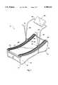
- FIG. 1is a perspective view of one presently preferred embodiment of a curved deck treadmill
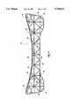
- FIG. 2is a side elevational view of the embodiment of FIG. 1 exposing one presently preferred arrangement of the internal components of the present invention
- FIG. 3is a cut-away view of the embodiment of FIG. 1;
- FIG. 4is a side elevational view of one presently preferred embodiment of one side of a support frame of one presently preferred embodiment of the present invention.
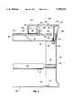
- FIG. 5is a exploded, fragmentary cross-sectional view of the embodiment of FIG. 2 taken along lines 5--5 of FIG. 2.
- the curved deck treadmill 10comprises a support frame 12 having a first side 20 and a second opposing side 22 and having a deck 56 supportably disposed therebetween.
- the deck 56comprises a first end 58, a second end 60, and an intermediate portion 62 disposed therebetween.
- the intermediate portion 62 of the deck 56is preferably formed having an arcuate configuration such that a significant portion of the intermediate portion 62 may be operably disposed dimensionally lower in longitudinal relationship to the first and second ends 58, 60 of the deck 56.
- a roller assembly 14is provided preferably comprising a first and second roller 78, 86.
- the first roller 78may be rotatably disposed contiguous the first end 58 of the deck 56 between the first side 20 and the second opposing side 22 of the support frame 12.
- a second roller 86is preferably disposed contiguous the second end 60 of the deck 56 between the first and second sides 20, 22 of the support frame 12.
- a belt 16is rotatably mounted in relation to the roller assembly 14 and operatively disposed in relation to the deck 56, thereby providing a structurally supported arcuate shaped, moveable surface on which a user may exercise.
- At least one crossbar 130may be structurally supported in relation to the support frame 12.
- the crossbar 130functionally supports a console 132 substantially above the upper surface area of the support frame 12, deck 56, and belt 16.
- the crossbar 130may be formed having a generally U-shaped configuration.
- the crossbar 130may comprise a pivotal engagement 140 which provides a means for pivotally engaging one or more handles 134, 144 in relation to the crossbar 130 at the opposing sides thereof 126, 128.
- the support frame 12preferably comprises a first side 20 and a second opposing side 22 which, in combination, provide a means for structurally supporting the curved deck treadmill 10 and the various components thereof.
- the support frame 12is preferably formed of a substantially sturdy, rigid material which provides sufficient structural integrity to support the curved deck treadmill 10 and a user exercising thereon.
- the support frame 12may be formed of any of numerous organic, synthetic or processed materials which are mostly thermoplastic or thermosetting polymers of high molecular weight with or without additives, such as, plasticizers, auto oxidants, extenders, colorants, ultraviolet light stabilizers, or fillers, which can be shaped, molded, cast, extruded, drawn, foamed or laminated.
- the support frame 12may be formed having a first side 20 being disposed substantially parallel a second opposing side 22, thereby providing a generally longitudinal alignment therebetween.
- first side 20 and the second side 22 of the support frame 12are relatively constructed having a substantially comparable structure and configuration, only the first side 20 will be operatively disclosed in detail herein. Any structural variations which exist between the first side 20 and the second opposing side 22 will be further disclosed herein, thus noting such variations which exist between the first side 20 and the second opposing side 22 will be further disclosed, whereby noting such variation(s).
- the first side 20 of the support frame 12includes a first end 24 and a second opposing end 26.
- the first and second ends 24, 26 of the first side 20are preferably disposed in corresponding relation to the first and second ends 58, 60 of the deck 56.
- a first journal housing 28may be formed substantially adjacent the first end 24 of the first side 20 of the support frame 12.
- the first journal housing 28is formed having an opening readily adapted to receive at least one journaling end (not shown) of the first roller 78.
- a second journal housing 34may be formed substantially adjacent the second end 26 of the first side 20 of the support frame 12 and include an opening readily adapted to receive at least one journaling end (not shown) of the second roller 86.
- the journal housings 28, 34 formed at the first and second ends 24, 26 of the first side 20 of the support frame 12, respectively,may be formed having an opening which provides a means for facilitating the introduction of the journaling ends of the respective first and second rollers 78, 86.
- the openingcomprises an elongated slot wherein the journaling ends of the first and second rollers 78, 86 may be slideably adjusted.
- a third journal housing 36may be formed in the first side 20 of the support frame 12, as best illustrated in FIGS. 2, 4 and 5.
- the third journal housing 36may be disposed dimensionally lower than the substantially horizontal displacement of the first and second journal housings 28, 34.
- the third journal housing 36is preferably formed including an opening having an internal periphery sufficient for introducing at least one journaling end 90 of the third roller 88 therein, as shown in FIG. 5.
- the journaling end 90 of the third roller 88is formed having a substantially cylindrical configuration comprising an outer diameter which is less than the internal diameter of the opening formed in the third journal housing 36. It will be readily appreciated by those skilled in the art, however, that other shapes, sizes and/or configurations of the journal housings 28, 34, 36 and/or the internal openings formed therein are possible as such to provide a means for introducing at least one journaling end of the first, second and third rollers 78, 86, 88, respectively, therein.
- journal housings 28, 34, 36 formed in the first side 20 of the support frame 12may be disposed in operative alignment with the journal housings formed in the second side 22 of the support frame 12.
- This arrangement of the journal housings 28, 34, 36 in both the first and second sides 20, 22 of the support frame 12preferably provides for the introduction and retention of the journaling ends of the corresponding rollers 78, 86, 88, thereby facilitating a means for rotating the rollers on a substantially fixed axis.
- journal housings 28, 34, 36 of the first and second sides 20, 22 of the support frame 12preferably receive the journaling ends of the respective rollers 78, 86, 88, it will be apparent to those skilled in the art that other mechanisms may be constructed and/or numerous other relative dispositions of the respective rollers may be anticipated in accordance with the inventive principles disclosed herein in order to achieve the desired results of the present invention. It is intended, therefore, that the examples provided herein be viewed as exemplary of the principles of the present invention, and not as restrictive to a particular structure or structures for implementing those principles.
- the belt 16 operably disposed in relation to the rollers 78, 86, 88may be formed comprising an endless construction which preferably consists of a sufficiently sturdy material.
- the belt 16may be formed of an endless sheet of a flexible canvas or a rubber-impregnated material.
- the belt 16may alternatively be formed of a thin, flat band of steel or a sufficiently tenacious polymeric or composite material.
- the belt 16can, of course, be formed of a wide variety of suitable materials which are consistent with the spirit and scope of the present invention.
- the belt 16is rotatably disposed in relation to the first roller 78, the second roller 86, and the third roller 88, whereby each roller 78, 86, 88 is preferably disposed in structural relation to the support frame 12 at their respectively preferred positions, as disclosed above.
- the tension of the belt 16may be readily tightened or loosened in relation to the disposition of the first and second rollers 78, 86 engageably disposed in the respective elongated slot of the journal housings 28, 34.
- a conventional fixation member(not shown) may be utilized to provide a means for disposing the journaling ends of the rollers 78, 86, 88 in a fixed and/or adjustable relationship to the respective opening or elongated slot formed in the journal housings 28, 34, 36 of the support frame 12.
- a deck slot 32may be formed which extends substantially the longitudinal length of the first side 20, as shown in FIG. 4.
- the deck slot 32is disposed such that the deck 56 may be insertably disposed therein.
- the deck slot 32comprises a substantially curvilinear configuration which substantially corresponds in dimensional shape to the arcuate configuration of the intermediate portion 62 of the deck 56.
- the deck slot 32is preferably formed having a sufficient size and depth sufficient to retain at least one longitudinal side of the deck 56 engageably inserted therein, such that any possible flexing of the deck 56 from the weight of a user will not generally unseat the deck 56 from the deck slot 32.
- the opposing longitudinal side of the deck 56is preferably disposed within the deck slot 32 formed in the second side 22 of the support frame 12.
- the deck 56is formed of a substantially sturdy, rigid material to provide sufficient structural integrity to adequately support the weight of a user exercising on the curved deck treadmill 10.
- the deck 56is preferably formed consisting of a wood laminate having an upper surface 66 that may be impregnated with a wax material to provide a means for reducing the coefficient of friction acting thereon.
- the deck 56may be formed of any of numerous organic, synthetic or processed materials which are mostly thermoplastic or thermosetting polymers of high molecular weight with or without additives, such as, plasticizers, auto oxidants, extenders, colorants, ultraviolet light stabilizers, or fillers, which can be shaped, molded, cast, extruded, drawn, foamed or laminated. It will be readily appreciated by those skilled in the art, however, that a wide variety of other suitable materials such as, metal or metal alloys, fiberglass, ceramic, graphite and/or other composite or polymeric materials are possible which are consistent with the spirit and scope of the present invention.
- the first side 20 of the support frame 12may comprise one or more rib seats 30 disposed adjacent the deck slot 32.
- the rib seats 30are preferably formed having an internal surface area sufficient for seating at least one end of a support rib 54 disposed therein.
- one or more support ribs 54extend substantially transverse dimensionally between the first and second sides 20, 22 of the support frame 12.
- the support ribs 54provide a means for structurally supporting the deck 56.
- the rib seats 30are preferably formed such that when the support ribs 54 are introduced therein, the deck 56 may be readily disposed within the respective deck slots 32 formed in the first and second sides 20, 22 of the support frame 12 and structurally supported by the support ribs 54 disposed in relation thereto.
- the support ribs 54are formed of a sufficiently sturdy, rigid material sufficient to provide adequate structural support to the deck 56.
- the support ribs 54may be formed of a rigid metal or metal alloy.
- suitable materialssuch as, fiberglass, ceramic, graphite, any of numerous organic, synthetic or processed materials which are mostly thermoplastic or thermosetting polymers of high molecular weight with or without additives, such as, plasticizers, auto oxidants, extenders, colorants, ultraviolet light stabilizers, or fillers, which can be shaped, molded, cast, extruded, drawn, foamed or laminated, and/or other composite materials are possible that are consistent with the spirit and scope of the present invention.
- the support ribs 54are formed having a generally elongated configuration which is capable of being seated in a corresponding rib seat 30 disposed in a spaced-apart relation in the first side 20 and the second opposing side 22 of the support frame 12. Accordingly, the rib seats 30 have a corresponding dimensional shape which provides a means for introducing and retaining the ends of the support ribs 54 therein.
- the quantity and disposition of rib seats 30 and engaging support ribs 54 supportably disposed in relation to the support frame 12may vary according to the structural integrity generally required to support the deck 56 and the weight of a user.
- the addition of rib seats 30 and support ribs 54 near the first and second ends 24, 26 of the support frame 12may increase the overall structural integrity of the deck 56 in relation to the support frame 12.
- the support frame 12may include a plurality of structural reinforcement members 50 disposed in relation to the first and second sides 20, 22, as best shown in FIG. 4. As illustrated, the plurality of reinforcement members 50 may be disposed horizontally, vertically, and/or diagonally throughout the sides 20, 22 to provide a means for increasing the ability of the first and second sides 20, 22 to resist buckling or a loss of structural integrity.
- the structural members 50are preferably formed along the interior surface of the first side 20 of the support frame 12. It will be readily appreciated by those skilled in the art, however, that other structural reinforcing components may be added to further enhance the supportable nature of the support frame 12 or for enhancing the inherent aesthetics of the device.
- the first side 20 of the support frame 12may comprise at least one conventional foot roller assembly 38 mountably disposed in relation thereto, as best shown in FIG. 2.
- the foot roller assembly 38preferably includes one or more wheels 42 rotatably connected thereto in such a manner so as to provide a means for readily moving the curved deck treadmill 10.
- the foot roller assembly 38may further comprise a force absorbing member 40 disposed in relation thereto which provides a means for absorbing any forces or shocks sustained while moving the present invention from one location to another.
- the force absorbing member 40may consist of a conventional shock absorber which is useful over rough surfaces in absorbing sudden movement, bounces, etc.
- the force absorbing member 40may also include a means for stabilizing the curved deck treadmill 10 at an elevated position so as to provide a means for inclining the front end 24 of the support frame 12 for increasing user workout.
- the force absorbing member 40may comprise a gas or oil filled shock or, in the alternative, an electric gear motor having a locking shaft which elevates the front end 24 of the support frame 12.
- the second opposing side 22 of the support frame 12is correspondingly similar in dimensional structure and configuration to that of the first side 20. Accordingly, the components disposed on or in relation to the first side 20 of the support frame 12 are preferably disposed on or in relation to the second side 22.
- the incorporation of substantially comparable sides 20, 22 of the support frame 12comprises one presently preferred embodiment. It is intended, therefore, that the example provided herein be viewed as exemplary of the principles of the present invention, and not as restrictive to a particular structure for implementing those principles. Accordingly, the utilization of a support frame having correspondingly similar sides is thus by way of illustration only and not by way of limitation.
- the curved deck treadmill 10may include one or more belt securing assemblies 94 which provide a means for retaining the endless belt 16 in a curvilinear configuration being substantially flush with the upper surface 66 of the deck 56.
- the belt securing assemblies 94provide a means for substantially conforming the inherent flexible nature of the belt 16 to the arcuate configuration of the intermediate portion 62 of the deck 56.
- one or more belt securing assemblies 94may be disposed in spaced-apart relation along the upper surface 66 of the intermediate portion 62 of the deck 56, as shown in FIG. 2, to sufficiently retain the belt 16 in operable disposition to the deck 56.
- the belt securing assembly 94comprises a roller 98 having an axle 100 which rotatably engages a mounting bracket 96.
- the mounting bracket 96is preferably disposed in relation to the roller 98 such that the roller 98 may engage the belt 16, thereby substantially retaining a side portion of the belt 16 substantially flush with the deck 56.
- the rollers 98 of the belt securing assembly 94preferably rotate in relation thereto.
- a cover member 68may be disposed in connection between the first and second sides 20, 22 of the support frame 12.
- the cover member 68is preferably formed providing a means for covering the internal components of the curved deck treadmill 10.
- the cover member 68may be removably disposed in connection to the first and second sides 20, 22 of the support frame 12 whereby allowing for easy access to the internal working components of the present invention.
- the cover member 68may be attached to the support frame 12 by a series of tabs 72 disposed along the outer edge 70 of the cover member 68 and arranged in such a manner so as to removably engage the first and second sides 20, 22, as illustrated depicted in FIG. 5.
- a cover member 168may provide a means for covering the belt securing assemblies 94 disposed in relation to the first and second sides 20, 22 of the support frame 12.
- the cover member 168which is disposed in relation to covering the belt securing assembly 94 may comprise a horizontal portion 104 disposed in relation to one or more vertical sides 106.
- the mounting bracket 96may be fixed to the cover member 168 such that it provides a means for assisting in the rotational alignment of the roller 98 of the belt securing assembly 94.
- at least one vertical side 106is disposed adjacent the roller 98 of the belt securing assembly 94 such that the vertical side 106 and the horizontal portion 104 of the cover member 168 substantially cover the belt securing assembly 94.
- one or more longitudinal grooves 110may be formed in the exterior surface of the horizontal portion 104 of the cover member 168, as best shown in FIGS. 1, 3 and 5.
- the cover member 168may include other structural components for either functional or aesthetic reasons.
- the cover members 68, 168are preferably formed of a substantially sturdy, semi-flexible material.
- the cover members 68, 168may be formed of any of numerous organic, synthetic or processed materials which are mostly thermoplastic or thermosetting polymers of high molecular weight with or without additives, such as, plasticizers, auto oxidants, extenders, colorants, ultraviolet light stabilizers, or fillers, which can be shaped, molded, cast, extruded, drawn, foamed or laminated.
- the belt securing assembly 94 and the corresponding cover member 68may be attached to the support frame 12 by a conventional fastening means.
- a bolt 118may be disposed through an aperture 112 formed in the cover member 168 and at least one aperture 114 formed in a respective side 20, 22 of the support frame 12.
- the bolt 118may be disposed through an aperture 116 formed in a support rib 54 which may further serve to secure the support rib 54 to the support frame 12.
- a longitudinal side 64 of the deck 56were to extend past the apertures formed in the cover member 168 and the support frame 12, a corresponding through-bore (not shown) may be formed in the deck 56 and disposed in alignment with the other apertures. If desired, a locking nut 120 may be disposed in relation to a first end of the bolt 118 to secure the preferred engagement outlined above between the various components of the curved deck treadmill 10.
- a driving means 84is operably connected to at least one roller to enable the rotation of the belt 16.
- the driving means 84preferably comprises a conventional electric motor for rotating the belt 16.
- a pulley 80is disposably mounted to the first roller 78 at the first end 24 of the support frame 12.
- a pulley belt 82may be engageably disposed between the pulley 80 and the motor 84 to provide a means for correspondingly rotating the first roller 78 upon the forced rotation of the pulley belt 82 by the motor 84.
- the motor 84may be mounted to the support frame 12 substantially adjacent the first end 58 and beneath the deck 56 by means of a fixation bracket (not shown). Alternatively, it will be readily appreciated by those skilled in the art, however, that the motor 84 may be engageably disposed in relation to the second or third rollers 86, 88 to enable the rotation of the belt 16.
- the curved deck treadmill 10 or the present inventionmay be implemented without a driving means engageably disposed to a roller in order to facilitate the forced rotation of the belt 16. If so implemented, the rollers 78, 86 and 88 and the deck 56 should be generally calibrated in relation to the belt 16 to provide an optimal frictional resistance to enable a user to safely walk, jog, and/or run thereon, while still providing sufficient resistance to enable a user to exercise.
- a crossbar 130may be preferably formed having a generally U-shaped configuration and may be disposed in fixed relation to the first and second sides 20, 22 of the support frame 12 by means of conventional fasteners.
- the fastenersmay comprise one or more internally threaded seats 46 (as best shown in FIG. 4) wherein an appropriately sized fastener 48 may be introduced to provide a threaded or force-fit engagement therebetween for securing the first side 126 of the cross-bar 130 to the first side 20 of the support frame 12.
- a second end 128 of the crossbar 130may be similarly mounted in a preferably fixed engagement to the second side 22 of the support frame 12.
- crossbar 130 of the present inventionis illustrated and described in connection with a generally U-shaped configuration, those skilled in the art will recognize that various other geometrical configurations are likewise suitable.
- the use of a generally U-shaped configurationis thus by way of illustration only and not by way of limitation.
- a console 132is preferably mounted in relation to the cross-bar 130.
- the console 132may be mounted substantially above the support frame 12, the deck 56, and the belt 16 such that a user may view the information displayed on the console 132.
- the console 132preferably comprises a processor, a display, and may include input keys for entering user programmable options.
- the console 132may provide a variety of feedback data, such as elapsed time, speed, distance, pulse rate, and/or other functions and features, as desired.
- the console 132may incorporate additional external components and/or devices in carrying out its function.
- the console 132may include one or more sensors for ascertaining the rotational speed of the belt 16, a sensor for determining the pulse or heart rate of a user, a device for controlling the speed of the motor, etc.
- sensors for ascertaining the rotational speed of the belt 16a sensor for determining the pulse or heart rate of a user
- a device for controlling the speed of the motoretc.
- Such external components and/or devicesare not specifically shown in the Figures, it is clearly contemplated by the present invention that such electronic and/or mechanical equipment are readily anticipated herein for utilization with the present invention.
- the crossbar 130may comprise a pivotal engagement 140 which provides a means for pivotally engaging one or more handles 134, 144 in relation to the opposing sides 126, 128 of the crossbar 130, as illustrated in FIGS. 1, 2 and 3.
- the handles 134, 144may be constructed of any suitable rigid material.
- the handles 134, 144may be formed of a metal or metal alloy, wood, fiberglass, graphite, ceramic, plastic or any other suitable composite material.
- the handles 134, 144may include a gripping member (not shown) preferably disposed substantially adjacent the distal ends of the handles 134, 144 to enable a user to more easily grip the handle.
- a rubber gripmay be disposed in relation to the distal end 138 of the handle 134, 144 and positioned so that a user may grasp the gripping member of the handle 134, 144 when exercising.
- a first handle 134includes a pivot end 136, a distal end 138 and an intermediate portion disposed therebetween.
- the pivot end 136 of the first handle 134may be pivotally connected to the first side 126 of the crossbar 130 by means of a pivotal connection 140.
- the pivotal connection 140comprises a conventional through-bore and a pivot pin 142 operably disposed therein, whereby providing a pivoting means for the handle 134 to pivot in relation thereto.
- a second handle 144may be pivotally connected to the second side 128 of the crossbar 130.
- the handles 134 and 144are preferably positioned such that a user may grasp approximate the distal end 138 of the handles 134, 144 while exercising and, accordingly, pivot the handles back and forth in correspondence to the user's stride, whereby potentially invoking an aerobic workout.
- the handles 134, 144may be provided with some conventional form of resistance to further facilitate the exercising of the upper body of a user.
- first 134 and second handles 144are described herein as being connected to the opposing sides 126, 128 of the crossbar 130 by a pivotal connection 140, it will be readily appreciated by those skilled in the art that other points of connection are possible.
- the first and second handles 134, 144may be pivotally connected to the first and second sides 20, 22, respectively, of the support frame 12.
- the handles 134, 144may be operably connected to the motor 84 to provide a means for encouraging a user to maintain a predetermined, constant stride on the rotating belt 16, while maintaining a constant back-and-forth arm movement.
- the present inventionprovides a novel curved deck treadmill which provides a structurally supported arcuate shaped moveable surface on which a user may exercise.
- the present inventionfurther provides a curved deck treadmill which maximizes the upper surface area of the belt by effective disposition of the driving means.
- the present inventionsubstantially prevents a user from falling off the back of the treadmill and whereby serves to keep the user centered on the upper surface of the rotating belt without encumbering the natural body motion of the user exercising thereon.
- the curved deck treadmill of the present inventioncomprises a first end and a second end disposed substantially parallel in dimensional relationship and including a deck having an intermediate portion disposed therebetween comprising a substantially arcuate longitudinal configuration which is disposed lower in dimensional relation to the first and second ends.
- the novel configuration of the present inventionis capable of reducing the physical impact to the joints and muscles (e.g., the knees and back) of a user, thus providing an operative device having rehabilitative functionality.
- the present inventionprovides a continuous, smooth exercising motion capable of providing meaningful exercise comfort, thereby facilitating an upper surface which supportably provides for a longer stride with more flexibility.
Landscapes
- Health & Medical Sciences (AREA)
- Cardiology (AREA)
- Vascular Medicine (AREA)
- General Health & Medical Sciences (AREA)
- Physical Education & Sports Medicine (AREA)
- Rehabilitation Tools (AREA)
Abstract
Description
Claims (19)
Priority Applications (2)
| Application Number | Priority Date | Filing Date | Title |
|---|---|---|---|
| US08/721,724US5709632A (en) | 1996-09-27 | 1996-09-27 | Curved deck treadmill |
| US09/009,582US5897461A (en) | 1996-09-27 | 1998-01-20 | Exercise treadmill |
Applications Claiming Priority (2)
| Application Number | Priority Date | Filing Date | Title |
|---|---|---|---|
| US08/721,724US5709632A (en) | 1996-09-27 | 1996-09-27 | Curved deck treadmill |
| PCT/US1998/000935WO1999036129A1 (en) | 1998-01-20 | 1998-01-20 | Exercise treadmill |
Related Child Applications (1)
| Application Number | Title | Priority Date | Filing Date |
|---|---|---|---|
| US09/009,582Continuation-In-PartUS5897461A (en) | 1996-09-27 | 1998-01-20 | Exercise treadmill |
Publications (1)
| Publication Number | Publication Date |
|---|---|
| US5709632Atrue US5709632A (en) | 1998-01-20 |
Family
ID=26793889
Family Applications (1)
| Application Number | Title | Priority Date | Filing Date |
|---|---|---|---|
| US08/721,724Expired - Fee RelatedUS5709632A (en) | 1996-09-27 | 1996-09-27 | Curved deck treadmill |
Country Status (1)
| Country | Link |
|---|---|
| US (1) | US5709632A (en) |
Cited By (80)
| Publication number | Priority date | Publication date | Assignee | Title |
|---|---|---|---|---|
| US5897461A (en)* | 1996-09-27 | 1999-04-27 | Precor Incorporated | Exercise treadmill |
| US5910072A (en)* | 1997-12-03 | 1999-06-08 | Stairmaster Sports/Medical Products, Inc. | Exercise apparatus |
| EP0963766A1 (en)* | 1998-06-12 | 1999-12-15 | Leao Wang | Buffer structure for a jogging machine |
| US6053848A (en)* | 1998-08-24 | 2000-04-25 | Eschenbach; Paul William | Treadmill deck suspension |
| US6368253B1 (en)* | 1998-02-19 | 2002-04-09 | Mathew Harrigan | In-line roller skate exercise device |
| US20020151413A1 (en)* | 1997-10-28 | 2002-10-17 | Dalebout William T. | Fold-out treadmill |
| WO2003022370A1 (en)* | 2001-09-06 | 2003-03-20 | Icon Ip Inc. | Method and apparatus for treadmill with frameless treadbase |
| US6561953B1 (en)* | 2000-04-21 | 2003-05-13 | Susan Chang | Supporting frame of running exerciser made of plasticizing material |
| EP1312395A1 (en) | 2001-11-20 | 2003-05-21 | Leao Wang | Speed control rocker arm for an electric treadmill |
| EP1316332A1 (en) | 2001-11-28 | 2003-06-04 | Leao Wang | Rocker arm for an electric treadmill |
| US20040005961A1 (en)* | 2000-02-09 | 2004-01-08 | Iund Neal Alexander | Lightweight, clear-path, equilibrated treadmill |
| US6689019B2 (en) | 2001-03-30 | 2004-02-10 | Nautilus, Inc. | Exercise machine |
| US20040152566A1 (en)* | 2003-01-30 | 2004-08-05 | Chien-Chung Yeh | External plastic structure of a treadmill |
| US20040192514A1 (en)* | 2003-02-28 | 2004-09-30 | Nautilus, Inc. | Exercise device with treadles |
| US20040209738A1 (en)* | 2003-02-28 | 2004-10-21 | Nautilus, Inc. | System and method for controlling an exercise apparatus |
| US20040214693A1 (en)* | 2003-02-28 | 2004-10-28 | Nautilus, Inc. | Dual deck exercise device |
| US6860839B1 (en) | 2003-04-07 | 2005-03-01 | Michael P. Dice | Universal rear safety cover for treadmills |
| US20050148442A1 (en)* | 1996-01-30 | 2005-07-07 | Watterson Scott R. | Reorienting treadmill |
| US20050209059A1 (en)* | 2003-02-28 | 2005-09-22 | Nautilus, Inc. | Upper body exercise and flywheel enhanced dual deck treadmills |
| EP1690569A1 (en) | 2005-02-12 | 2006-08-16 | Leao Wang | Extendable swing arm assembly for a treadmill |
| US7097593B2 (en) | 2003-08-11 | 2006-08-29 | Nautilus, Inc. | Combination of treadmill and stair climbing machine |
| US7169089B2 (en) | 2003-06-06 | 2007-01-30 | Rodgers Jr Robert E | Compact variable path exercise apparatus with a relatively long cam surface |
| US7169088B2 (en) | 2003-06-06 | 2007-01-30 | Rodgers Jr Robert E | Compact variable path exercise apparatus |
| US7172531B2 (en) | 2003-06-06 | 2007-02-06 | Rodgers Jr Robert E | Variable stride exercise apparatus |
| US7201705B2 (en) | 2003-06-06 | 2007-04-10 | Rodgers Jr Robert E | Exercise apparatus with a variable stride system |
| US7214168B2 (en) | 2003-06-06 | 2007-05-08 | Rodgers Jr Robert E | Variable path exercise apparatus |
| EP1601419A4 (en)* | 2003-02-28 | 2007-07-04 | Nautilus Inc | DOUBLE PLATFORM EXERCISE DEVICE |
| US7244217B2 (en) | 2003-06-06 | 2007-07-17 | Rodgers Jr Robert E | Exercise apparatus that allows user varied stride length |
| FR2899489A1 (en)* | 2006-04-06 | 2007-10-12 | Forhouse Corp | Cushion device for e.g. treadmill, has elastic member e.g. spring, with ends urging exercise machine and linkage, to be elastically deformed when linkage is swung, where angle between linkage and ground is less than ninety degrees |
| US20120270705A1 (en)* | 2011-04-23 | 2012-10-25 | Chiu Hsiang Lo | Inexpensive Treadmill with a Concave Platform |
| US8308619B1 (en) | 2009-11-02 | 2012-11-13 | Astilean Aurel A | Leg-powered treadmill |
| US8343016B1 (en) | 2009-11-02 | 2013-01-01 | Astilean Aurel A | Leg-powered treadmill |
| US20140024500A1 (en)* | 2012-07-23 | 2014-01-23 | Icon Health & Fitness, Inc. | Treadmill with Deck Vibration |
| US20140024502A1 (en)* | 2012-07-23 | 2014-01-23 | Icon Health & Fitness, Inc. | Exercise Cycle with Vibration Capabilities |
| US8864627B2 (en) | 2009-03-17 | 2014-10-21 | Woodway Usa, Inc. | Power generating manually operated treadmill |
| WO2014160057A3 (en)* | 2013-03-14 | 2014-12-04 | Astilean Alex | Leg-powered treadmill |
| USD723636S1 (en)* | 2013-10-17 | 2015-03-03 | Paul G. Kahmann | Walking slide mill |
| US20160023039A1 (en)* | 2014-07-25 | 2016-01-28 | Technogym S.P.A. | Curved treadmill |
| US20160144224A1 (en)* | 2014-11-26 | 2016-05-26 | Icon Health & Fitness, Inc. | Treadmill with Slatted Tread Belt |
| EP3031499A1 (en)* | 2014-12-12 | 2016-06-15 | Technogym S.p.A. | Manual treadmill |
| US9675839B2 (en) | 2014-11-26 | 2017-06-13 | Icon Health & Fitness, Inc. | Treadmill with a tensioning mechanism for a slatted tread belt |
| ITUB20159481A1 (en)* | 2015-12-29 | 2017-06-29 | Technogym Spa | Curved manual rotating mat |
| US20170340917A1 (en)* | 2016-05-27 | 2017-11-30 | Chung-Fu Chang | Treadmill having a curved treadmill deck |
| US9898918B2 (en) | 2014-03-12 | 2018-02-20 | Precor Incorporated | Treadmill belt wear notification system |
| US9968823B2 (en) | 2015-08-28 | 2018-05-15 | Icon Health & Fitness, Inc. | Treadmill with suspended tread belt |
| US10188890B2 (en) | 2013-12-26 | 2019-01-29 | Icon Health & Fitness, Inc. | Magnetic resistance mechanism in a cable machine |
| CN109432695A (en)* | 2018-11-27 | 2019-03-08 | 南安紫鲸铃工业设计有限公司 | A kind of treadmill running style foothold auxiliary correcting device of body shaping fat reducing |
| US10238911B2 (en) | 2016-07-01 | 2019-03-26 | Woodway Usa, Inc. | Motorized treadmill with motor braking mechanism and methods of operating same |
| US10252109B2 (en) | 2016-05-13 | 2019-04-09 | Icon Health & Fitness, Inc. | Weight platform treadmill |
| US10258828B2 (en) | 2015-01-16 | 2019-04-16 | Icon Health & Fitness, Inc. | Controls for an exercise device |
| US10272317B2 (en) | 2016-03-18 | 2019-04-30 | Icon Health & Fitness, Inc. | Lighted pace feature in a treadmill |
| US10279212B2 (en) | 2013-03-14 | 2019-05-07 | Icon Health & Fitness, Inc. | Strength training apparatus with flywheel and related methods |
| US10293211B2 (en) | 2016-03-18 | 2019-05-21 | Icon Health & Fitness, Inc. | Coordinated weight selection |
| CN109847265A (en)* | 2019-01-28 | 2019-06-07 | 浙江畅跑体育用品有限公司 | Machine for walking |
| US10343017B2 (en) | 2016-11-01 | 2019-07-09 | Icon Health & Fitness, Inc. | Distance sensor for console positioning |
| US10376736B2 (en) | 2016-10-12 | 2019-08-13 | Icon Health & Fitness, Inc. | Cooling an exercise device during a dive motor runway condition |
| US10426989B2 (en) | 2014-06-09 | 2019-10-01 | Icon Health & Fitness, Inc. | Cable system incorporated into a treadmill |
| US10433612B2 (en) | 2014-03-10 | 2019-10-08 | Icon Health & Fitness, Inc. | Pressure sensor to quantify work |
| US10441844B2 (en) | 2016-07-01 | 2019-10-15 | Icon Health & Fitness, Inc. | Cooling systems and methods for exercise equipment |
| US10471299B2 (en) | 2016-07-01 | 2019-11-12 | Icon Health & Fitness, Inc. | Systems and methods for cooling internal exercise equipment components |
| US10493349B2 (en) | 2016-03-18 | 2019-12-03 | Icon Health & Fitness, Inc. | Display on exercise device |
| US10500473B2 (en) | 2016-10-10 | 2019-12-10 | Icon Health & Fitness, Inc. | Console positioning |
| US10537764B2 (en) | 2015-08-07 | 2020-01-21 | Icon Health & Fitness, Inc. | Emergency stop with magnetic brake for an exercise device |
| US10543395B2 (en) | 2016-12-05 | 2020-01-28 | Icon Health & Fitness, Inc. | Offsetting treadmill deck weight during operation |
| US10561877B2 (en) | 2016-11-01 | 2020-02-18 | Icon Health & Fitness, Inc. | Drop-in pivot configuration for stationary bike |
| US10561894B2 (en) | 2016-03-18 | 2020-02-18 | Icon Health & Fitness, Inc. | Treadmill with removable supports |
| US10625114B2 (en) | 2016-11-01 | 2020-04-21 | Icon Health & Fitness, Inc. | Elliptical and stationary bicycle apparatus including row functionality |
| US10625137B2 (en) | 2016-03-18 | 2020-04-21 | Icon Health & Fitness, Inc. | Coordinated displays in an exercise device |
| US10661114B2 (en) | 2016-11-01 | 2020-05-26 | Icon Health & Fitness, Inc. | Body weight lift mechanism on treadmill |
| USD888845S1 (en)* | 2019-10-18 | 2020-06-30 | Jiangxi EQI Industrial Co., Ltd | Treadmill |
| USD889569S1 (en)* | 2019-10-18 | 2020-07-07 | Jiangxi EQI Industrial Co., Ltd | Treadmill |
| US10702736B2 (en) | 2017-01-14 | 2020-07-07 | Icon Health & Fitness, Inc. | Exercise cycle |
| US10709926B2 (en) | 2015-10-06 | 2020-07-14 | Woodway Usa, Inc. | Treadmill |
| US20200238131A1 (en)* | 2019-01-28 | 2020-07-30 | Zhejiang Ciapo Sporting Goods Co., Ltd | Walking Machine |
| US10729965B2 (en) | 2017-12-22 | 2020-08-04 | Icon Health & Fitness, Inc. | Audible belt guide in a treadmill |
| USD902332S1 (en)* | 2018-01-05 | 2020-11-17 | Peloton Interactive, Inc. | Treadmill deck |
| US10953305B2 (en) | 2015-08-26 | 2021-03-23 | Icon Health & Fitness, Inc. | Strength exercise mechanisms |
| USD930089S1 (en) | 2019-03-12 | 2021-09-07 | Woodway Usa, Inc. | Treadmill |
| US11451108B2 (en) | 2017-08-16 | 2022-09-20 | Ifit Inc. | Systems and methods for axial impact resistance in electric motors |
| US12343590B1 (en)* | 2024-02-16 | 2025-07-01 | Piao Zeng | Walking/treadmill with integrated base and manufacturing method for the integrated base |
Citations (11)
| Publication number | Priority date | Publication date | Assignee | Title |
|---|---|---|---|---|
| US1211765A (en)* | 1915-01-09 | 1917-01-09 | Adrian Peter Schmidt | Health-exerciser. |
| US3554541A (en)* | 1969-03-03 | 1971-01-12 | Faye Spoth | Exercise treadmill with convex surface |
| US3642279A (en)* | 1970-02-11 | 1972-02-15 | John W Cutter | Treadmill jogger |
| US4389047A (en)* | 1981-01-02 | 1983-06-21 | Hall Lawrence W | Rotary exercise device |
| US4616822A (en)* | 1984-08-01 | 1986-10-14 | Trulaske James A | Exercise treadmill |
| US4938473A (en)* | 1988-03-24 | 1990-07-03 | Clayton Lee R | Treadmill with trampoline-like surface |
| US5100127A (en)* | 1990-06-18 | 1992-03-31 | Melnick Dennis M | Physical exercise treadmill for quadrupeds |
| US5125361A (en)* | 1991-03-11 | 1992-06-30 | Rowlands Scott D | Tread drum for animals |
| US5391129A (en)* | 1992-06-04 | 1995-02-21 | Promotech Corporation | Swimmer training device |
| US5431612A (en)* | 1994-06-24 | 1995-07-11 | Nordictrack, Inc. | Treadmill exercise apparatus with one-way clutch |
| US5575740A (en)* | 1993-09-30 | 1996-11-19 | Piaget; Gary D. | Striding exerciser with upwardly curved tracks |
- 1996
- 1996-09-27USUS08/721,724patent/US5709632A/ennot_activeExpired - Fee Related
Patent Citations (11)
| Publication number | Priority date | Publication date | Assignee | Title |
|---|---|---|---|---|
| US1211765A (en)* | 1915-01-09 | 1917-01-09 | Adrian Peter Schmidt | Health-exerciser. |
| US3554541A (en)* | 1969-03-03 | 1971-01-12 | Faye Spoth | Exercise treadmill with convex surface |
| US3642279A (en)* | 1970-02-11 | 1972-02-15 | John W Cutter | Treadmill jogger |
| US4389047A (en)* | 1981-01-02 | 1983-06-21 | Hall Lawrence W | Rotary exercise device |
| US4616822A (en)* | 1984-08-01 | 1986-10-14 | Trulaske James A | Exercise treadmill |
| US4938473A (en)* | 1988-03-24 | 1990-07-03 | Clayton Lee R | Treadmill with trampoline-like surface |
| US5100127A (en)* | 1990-06-18 | 1992-03-31 | Melnick Dennis M | Physical exercise treadmill for quadrupeds |
| US5125361A (en)* | 1991-03-11 | 1992-06-30 | Rowlands Scott D | Tread drum for animals |
| US5391129A (en)* | 1992-06-04 | 1995-02-21 | Promotech Corporation | Swimmer training device |
| US5575740A (en)* | 1993-09-30 | 1996-11-19 | Piaget; Gary D. | Striding exerciser with upwardly curved tracks |
| US5431612A (en)* | 1994-06-24 | 1995-07-11 | Nordictrack, Inc. | Treadmill exercise apparatus with one-way clutch |
Cited By (152)
| Publication number | Priority date | Publication date | Assignee | Title |
|---|---|---|---|---|
| US7540828B2 (en) | 1996-01-30 | 2009-06-02 | Icon Ip, Inc. | Reorienting treadmill |
| US20050148443A1 (en)* | 1996-01-30 | 2005-07-07 | Watterson Scott R. | Reorienting treadmill |
| US6974404B1 (en) | 1996-01-30 | 2005-12-13 | Icon Ip, Inc. | Reorienting treadmill |
| US20050148442A1 (en)* | 1996-01-30 | 2005-07-07 | Watterson Scott R. | Reorienting treadmill |
| US5897461A (en)* | 1996-09-27 | 1999-04-27 | Precor Incorporated | Exercise treadmill |
| US20020151413A1 (en)* | 1997-10-28 | 2002-10-17 | Dalebout William T. | Fold-out treadmill |
| US7192388B2 (en) | 1997-10-28 | 2007-03-20 | Icon Health & Fitness, Inc. | Fold-out treadmill |
| US5910072A (en)* | 1997-12-03 | 1999-06-08 | Stairmaster Sports/Medical Products, Inc. | Exercise apparatus |
| US6368253B1 (en)* | 1998-02-19 | 2002-04-09 | Mathew Harrigan | In-line roller skate exercise device |
| EP0963766A1 (en)* | 1998-06-12 | 1999-12-15 | Leao Wang | Buffer structure for a jogging machine |
| US6053848A (en)* | 1998-08-24 | 2000-04-25 | Eschenbach; Paul William | Treadmill deck suspension |
| US20040005961A1 (en)* | 2000-02-09 | 2004-01-08 | Iund Neal Alexander | Lightweight, clear-path, equilibrated treadmill |
| US6561953B1 (en)* | 2000-04-21 | 2003-05-13 | Susan Chang | Supporting frame of running exerciser made of plasticizing material |
| US7341542B2 (en) | 2001-03-30 | 2008-03-11 | Nautilus, Inc. | Exercise machine |
| US6689019B2 (en) | 2001-03-30 | 2004-02-10 | Nautilus, Inc. | Exercise machine |
| US20070298936A1 (en)* | 2001-03-30 | 2007-12-27 | Nautilus, Inc. | Exercise machine |
| US20040132583A1 (en)* | 2001-03-30 | 2004-07-08 | Nautilus, Inc. | Exercise machine |
| US7377882B2 (en) | 2001-09-06 | 2008-05-27 | Icon Ip, Inc. | Method and apparatus for treadmill with frameless treadbase |
| US20060217236A1 (en)* | 2001-09-06 | 2006-09-28 | Watterson Scott R | Method and apparatus for treadmill with frameless treadbase |
| US6743153B2 (en) | 2001-09-06 | 2004-06-01 | Icon Ip, Inc. | Method and apparatus for treadmill with frameless treadbase |
| US20040176217A1 (en)* | 2001-09-06 | 2004-09-09 | Watterson Scott R. | Method and apparatus for treadmill with frameless treadbase |
| US7052442B2 (en) | 2001-09-06 | 2006-05-30 | Icon Ip, Inc. | Method and apparatus for treadmill with frameless treadbase |
| WO2003022370A1 (en)* | 2001-09-06 | 2003-03-20 | Icon Ip Inc. | Method and apparatus for treadmill with frameless treadbase |
| AU2002315011B2 (en)* | 2001-09-06 | 2006-10-05 | IFIT, Inc. | Method and apparatus for treadmill with frameless treadbase |
| EP1312395A1 (en) | 2001-11-20 | 2003-05-21 | Leao Wang | Speed control rocker arm for an electric treadmill |
| EP1316332A1 (en) | 2001-11-28 | 2003-06-04 | Leao Wang | Rocker arm for an electric treadmill |
| US20040152566A1 (en)* | 2003-01-30 | 2004-08-05 | Chien-Chung Yeh | External plastic structure of a treadmill |
| US9352187B2 (en) | 2003-02-28 | 2016-05-31 | Nautilus, Inc. | Dual deck exercise device |
| US7967730B2 (en) | 2003-02-28 | 2011-06-28 | Nautilus, Inc. | System and method for controlling an exercise apparatus |
| US20100062904A1 (en)* | 2003-02-28 | 2010-03-11 | Nautilus, Inc. | System and method for controlling an exercise apparatus |
| US8734299B2 (en) | 2003-02-28 | 2014-05-27 | Nautilus, Inc. | Upper body exercise and flywheel enhanced dual deck treadmills |
| US8734300B2 (en) | 2003-02-28 | 2014-05-27 | Nautilus, Inc. | Dual deck exercise device |
| US8696524B2 (en) | 2003-02-28 | 2014-04-15 | Nautilus, Inc. | Dual deck exercise device |
| US20050209059A1 (en)* | 2003-02-28 | 2005-09-22 | Nautilus, Inc. | Upper body exercise and flywheel enhanced dual deck treadmills |
| US20040214693A1 (en)* | 2003-02-28 | 2004-10-28 | Nautilus, Inc. | Dual deck exercise device |
| US8550962B2 (en) | 2003-02-28 | 2013-10-08 | Nautilus, Inc. | Dual deck exercise device |
| EP1601419A4 (en)* | 2003-02-28 | 2007-07-04 | Nautilus Inc | DOUBLE PLATFORM EXERCISE DEVICE |
| US8147385B2 (en) | 2003-02-28 | 2012-04-03 | Nautilus, Inc. | Upper body exercise and flywheel enhanced dual deck treadmills |
| US9308415B2 (en) | 2003-02-28 | 2016-04-12 | Nautilus, Inc. | Upper body exercise and flywheel enhanced dual deck treadmills |
| US20040192514A1 (en)* | 2003-02-28 | 2004-09-30 | Nautilus, Inc. | Exercise device with treadles |
| US20110034303A1 (en)* | 2003-02-28 | 2011-02-10 | Nautilus, Inc. | Upper body exercise and flywheel enhanced dual deck treadmills |
| US20040209738A1 (en)* | 2003-02-28 | 2004-10-21 | Nautilus, Inc. | System and method for controlling an exercise apparatus |
| US7811209B2 (en) | 2003-02-28 | 2010-10-12 | Nautilus, Inc. | Upper body exchange and flywheel enhanced dual deck treadmills |
| US7517303B2 (en) | 2003-02-28 | 2009-04-14 | Nautilus, Inc. | Upper body exercise and flywheel enhanced dual deck treadmills |
| US7618346B2 (en) | 2003-02-28 | 2009-11-17 | Nautilus, Inc. | System and method for controlling an exercise apparatus |
| US7553260B2 (en) | 2003-02-28 | 2009-06-30 | Nautilus, Inc. | Exercise device with treadles |
| US20090176626A1 (en)* | 2003-02-28 | 2009-07-09 | Nautilus, Inc. | Upper body exercise and flywheel enhanced dual deck treadmills |
| US6860839B1 (en) | 2003-04-07 | 2005-03-01 | Michael P. Dice | Universal rear safety cover for treadmills |
| US7201705B2 (en) | 2003-06-06 | 2007-04-10 | Rodgers Jr Robert E | Exercise apparatus with a variable stride system |
| US7179201B2 (en) | 2003-06-06 | 2007-02-20 | Rodgers Jr Robert E | Variable stride exercise apparatus |
| US7316632B2 (en) | 2003-06-06 | 2008-01-08 | Rodgers Jr Robert E | Variable stride exercise apparatus |
| US7244217B2 (en) | 2003-06-06 | 2007-07-17 | Rodgers Jr Robert E | Exercise apparatus that allows user varied stride length |
| US7169089B2 (en) | 2003-06-06 | 2007-01-30 | Rodgers Jr Robert E | Compact variable path exercise apparatus with a relatively long cam surface |
| US7214168B2 (en) | 2003-06-06 | 2007-05-08 | Rodgers Jr Robert E | Variable path exercise apparatus |
| US7169088B2 (en) | 2003-06-06 | 2007-01-30 | Rodgers Jr Robert E | Compact variable path exercise apparatus |
| US7172531B2 (en) | 2003-06-06 | 2007-02-06 | Rodgers Jr Robert E | Variable stride exercise apparatus |
| US7097593B2 (en) | 2003-08-11 | 2006-08-29 | Nautilus, Inc. | Combination of treadmill and stair climbing machine |
| EP1690569A1 (en) | 2005-02-12 | 2006-08-16 | Leao Wang | Extendable swing arm assembly for a treadmill |
| FR2899489A1 (en)* | 2006-04-06 | 2007-10-12 | Forhouse Corp | Cushion device for e.g. treadmill, has elastic member e.g. spring, with ends urging exercise machine and linkage, to be elastically deformed when linkage is swung, where angle between linkage and ground is less than ninety degrees |
| US11465005B2 (en) | 2009-03-17 | 2022-10-11 | Woodway Usa, Inc. | Manually powered treadmill |
| US20150352400A1 (en)* | 2009-03-17 | 2015-12-10 | Woodway Usa, Inc. | Manual treadmill and methods of operating the same |
| US12090356B2 (en) | 2009-03-17 | 2024-09-17 | Woodway Usa, Inc. | Manually powered treadmill |
| US12115405B2 (en) | 2009-03-17 | 2024-10-15 | Woodway Usa, Inc. | Treadmill with electromechanical brake |
| US8864627B2 (en) | 2009-03-17 | 2014-10-21 | Woodway Usa, Inc. | Power generating manually operated treadmill |
| US11590377B2 (en) | 2009-03-17 | 2023-02-28 | Woodway Usa, Inc. | Manually powered treadmill |
| US9956450B2 (en) | 2009-03-17 | 2018-05-01 | Woodway Usa, Inc. | Power generating manually operated treadmill |
| US8986169B2 (en) | 2009-03-17 | 2015-03-24 | Woodway Usa, Inc. | Manual treadmill and methods of operating the same |
| US11179589B2 (en) | 2009-03-17 | 2021-11-23 | Woodway Usa, Inc. | Treadmill with electromechanical brake |
| US9039580B1 (en) | 2009-03-17 | 2015-05-26 | Woodway Usa, Inc. | Manual treadmill and methods of operating the same |
| USD736866S1 (en) | 2009-03-17 | 2015-08-18 | Woodway Usa, Inc. | Treadmill |
| US9114276B2 (en) | 2009-03-17 | 2015-08-25 | Woodway Usa, Inc. | Manual treadmill and methods of operating the same |
| US10850150B2 (en) | 2009-03-17 | 2020-12-01 | Woodway Usa, Inc. | Manually powered treadmill with variable braking resistance |
| US10265566B2 (en)* | 2009-03-17 | 2019-04-23 | Woodway Usa, Inc. | Manual treadmill and methods of operating the same |
| US9216316B2 (en) | 2009-03-17 | 2015-12-22 | Woodway Usa, Inc. | Power generating manually operated treadmill |
| US10799745B2 (en) | 2009-03-17 | 2020-10-13 | Woodway Usa, Inc. | Manual treadmill and methods of operating the same |
| US10434354B2 (en) | 2009-03-17 | 2019-10-08 | Woodway Usa, Inc. | Power generating manually operated treadmill |
| US10561884B2 (en) | 2009-03-17 | 2020-02-18 | Woodway Usa, Inc. | Manual treadmill and methods of operating the same |
| USD753245S1 (en) | 2009-03-17 | 2016-04-05 | Woodway Usa, Inc. | Treadmill |
| US10561883B2 (en) | 2009-03-17 | 2020-02-18 | Woodway Usa, Inc. | Manually powered treadmill with variable braking resistance |
| USD753776S1 (en) | 2009-03-17 | 2016-04-12 | Woodway Usa, Inc. | Treadmill |
| US8308619B1 (en) | 2009-11-02 | 2012-11-13 | Astilean Aurel A | Leg-powered treadmill |
| US8343016B1 (en) | 2009-11-02 | 2013-01-01 | Astilean Aurel A | Leg-powered treadmill |
| US8690738B1 (en)* | 2009-11-02 | 2014-04-08 | Alex A. Astilian | Leg-powered treadmill |
| US20120270705A1 (en)* | 2011-04-23 | 2012-10-25 | Chiu Hsiang Lo | Inexpensive Treadmill with a Concave Platform |
| US9278249B2 (en)* | 2012-07-23 | 2016-03-08 | Icon Health & Fitness, Inc. | Exercise cycle with vibration capabilities |
| US9289648B2 (en)* | 2012-07-23 | 2016-03-22 | Icon Health & Fitness, Inc. | Treadmill with deck vibration |
| US20140024500A1 (en)* | 2012-07-23 | 2014-01-23 | Icon Health & Fitness, Inc. | Treadmill with Deck Vibration |
| US20140024502A1 (en)* | 2012-07-23 | 2014-01-23 | Icon Health & Fitness, Inc. | Exercise Cycle with Vibration Capabilities |
| US10279212B2 (en) | 2013-03-14 | 2019-05-07 | Icon Health & Fitness, Inc. | Strength training apparatus with flywheel and related methods |
| WO2014160057A3 (en)* | 2013-03-14 | 2014-12-04 | Astilean Alex | Leg-powered treadmill |
| US9186539B2 (en)* | 2013-10-17 | 2015-11-17 | Paul G. Kahmann | Walking slide mill |
| US20150111702A1 (en)* | 2013-10-17 | 2015-04-23 | Paul G. Kahmann | Walking slide mill |
| USD723636S1 (en)* | 2013-10-17 | 2015-03-03 | Paul G. Kahmann | Walking slide mill |
| US10188890B2 (en) | 2013-12-26 | 2019-01-29 | Icon Health & Fitness, Inc. | Magnetic resistance mechanism in a cable machine |
| US10433612B2 (en) | 2014-03-10 | 2019-10-08 | Icon Health & Fitness, Inc. | Pressure sensor to quantify work |
| US9922528B2 (en) | 2014-03-12 | 2018-03-20 | Precor Incorporation | Fitness equipment unit service condition notification system |
| US9898918B2 (en) | 2014-03-12 | 2018-02-20 | Precor Incorporated | Treadmill belt wear notification system |
| US10426989B2 (en) | 2014-06-09 | 2019-10-01 | Icon Health & Fitness, Inc. | Cable system incorporated into a treadmill |
| US20160023039A1 (en)* | 2014-07-25 | 2016-01-28 | Technogym S.P.A. | Curved treadmill |
| US10143884B2 (en)* | 2014-07-25 | 2018-12-04 | Technogym S.P.A. | Curved treadmill |
| US20160144224A1 (en)* | 2014-11-26 | 2016-05-26 | Icon Health & Fitness, Inc. | Treadmill with Slatted Tread Belt |
| US9675839B2 (en) | 2014-11-26 | 2017-06-13 | Icon Health & Fitness, Inc. | Treadmill with a tensioning mechanism for a slatted tread belt |
| US9694234B2 (en)* | 2014-11-26 | 2017-07-04 | Icon Health & Fitness, Inc. | Treadmill with slatted tread belt |
| US20160166877A1 (en)* | 2014-12-12 | 2016-06-16 | Technogym S.P.A. | Manual treadmill |
| EP3031499A1 (en)* | 2014-12-12 | 2016-06-15 | Technogym S.p.A. | Manual treadmill |
| US10449411B2 (en)* | 2014-12-12 | 2019-10-22 | Technogym S.P.A. | Manual treadmill |
| US10258828B2 (en) | 2015-01-16 | 2019-04-16 | Icon Health & Fitness, Inc. | Controls for an exercise device |
| US10537764B2 (en) | 2015-08-07 | 2020-01-21 | Icon Health & Fitness, Inc. | Emergency stop with magnetic brake for an exercise device |
| US10953305B2 (en) | 2015-08-26 | 2021-03-23 | Icon Health & Fitness, Inc. | Strength exercise mechanisms |
| US9968823B2 (en) | 2015-08-28 | 2018-05-15 | Icon Health & Fitness, Inc. | Treadmill with suspended tread belt |
| US11826608B2 (en) | 2015-10-06 | 2023-11-28 | Woodway Usa, Inc. | Treadmill with intermediate member |
| US11369835B2 (en) | 2015-10-06 | 2022-06-28 | Woodway Usa, Inc. | Configuration of a running surface for a manual treadmill |
| US10709926B2 (en) | 2015-10-06 | 2020-07-14 | Woodway Usa, Inc. | Treadmill |
| US12208306B2 (en) | 2015-10-06 | 2025-01-28 | Woodway Usa, Inc. | Treadmill with intermediate member |
| ITUB20159481A1 (en)* | 2015-12-29 | 2017-06-29 | Technogym Spa | Curved manual rotating mat |
| US10537766B2 (en) | 2015-12-29 | 2020-01-21 | Technogym S.P.A. | Curved manual treadmill |
| US10493349B2 (en) | 2016-03-18 | 2019-12-03 | Icon Health & Fitness, Inc. | Display on exercise device |
| US10293211B2 (en) | 2016-03-18 | 2019-05-21 | Icon Health & Fitness, Inc. | Coordinated weight selection |
| US10561894B2 (en) | 2016-03-18 | 2020-02-18 | Icon Health & Fitness, Inc. | Treadmill with removable supports |
| US10272317B2 (en) | 2016-03-18 | 2019-04-30 | Icon Health & Fitness, Inc. | Lighted pace feature in a treadmill |
| US10625137B2 (en) | 2016-03-18 | 2020-04-21 | Icon Health & Fitness, Inc. | Coordinated displays in an exercise device |
| US10252109B2 (en) | 2016-05-13 | 2019-04-09 | Icon Health & Fitness, Inc. | Weight platform treadmill |
| US20170340917A1 (en)* | 2016-05-27 | 2017-11-30 | Chung-Fu Chang | Treadmill having a curved treadmill deck |
| US10039952B2 (en)* | 2016-05-27 | 2018-08-07 | Chung-Fu Chang | Treadmill having a curved treadmill deck |
| US10441844B2 (en) | 2016-07-01 | 2019-10-15 | Icon Health & Fitness, Inc. | Cooling systems and methods for exercise equipment |
| US11420092B2 (en) | 2016-07-01 | 2022-08-23 | Woodway Usa, Inc. | Motorized treadmill with motor braking mechanism and methods of operating same |
| US10238911B2 (en) | 2016-07-01 | 2019-03-26 | Woodway Usa, Inc. | Motorized treadmill with motor braking mechanism and methods of operating same |
| US10471299B2 (en) | 2016-07-01 | 2019-11-12 | Icon Health & Fitness, Inc. | Systems and methods for cooling internal exercise equipment components |
| US10905914B2 (en) | 2016-07-01 | 2021-02-02 | Woodway Usa, Inc. | Motorized treadmill with motor braking mechanism and methods of operating same |
| US10500473B2 (en) | 2016-10-10 | 2019-12-10 | Icon Health & Fitness, Inc. | Console positioning |
| US10376736B2 (en) | 2016-10-12 | 2019-08-13 | Icon Health & Fitness, Inc. | Cooling an exercise device during a dive motor runway condition |
| US10561877B2 (en) | 2016-11-01 | 2020-02-18 | Icon Health & Fitness, Inc. | Drop-in pivot configuration for stationary bike |
| US10343017B2 (en) | 2016-11-01 | 2019-07-09 | Icon Health & Fitness, Inc. | Distance sensor for console positioning |
| US10625114B2 (en) | 2016-11-01 | 2020-04-21 | Icon Health & Fitness, Inc. | Elliptical and stationary bicycle apparatus including row functionality |
| US10661114B2 (en) | 2016-11-01 | 2020-05-26 | Icon Health & Fitness, Inc. | Body weight lift mechanism on treadmill |
| US10543395B2 (en) | 2016-12-05 | 2020-01-28 | Icon Health & Fitness, Inc. | Offsetting treadmill deck weight during operation |
| US10702736B2 (en) | 2017-01-14 | 2020-07-07 | Icon Health & Fitness, Inc. | Exercise cycle |
| US11451108B2 (en) | 2017-08-16 | 2022-09-20 | Ifit Inc. | Systems and methods for axial impact resistance in electric motors |
| US10729965B2 (en) | 2017-12-22 | 2020-08-04 | Icon Health & Fitness, Inc. | Audible belt guide in a treadmill |
| USD946097S1 (en) | 2018-01-05 | 2022-03-15 | Peloton Interactive, Inc. | Set of control knobs |
| USD902332S1 (en)* | 2018-01-05 | 2020-11-17 | Peloton Interactive, Inc. | Treadmill deck |
| USRE50446E1 (en) | 2018-01-05 | 2025-06-03 | Peloton Interactive, Inc. | Control knob |
| USRE50450E1 (en) | 2018-01-05 | 2025-06-10 | Peloton Interactive, Inc. | Combination of upright and handrail supports |
| CN109432695A (en)* | 2018-11-27 | 2019-03-08 | 南安紫鲸铃工业设计有限公司 | A kind of treadmill running style foothold auxiliary correcting device of body shaping fat reducing |
| CN109847265A (en)* | 2019-01-28 | 2019-06-07 | 浙江畅跑体育用品有限公司 | Machine for walking |
| US20200238131A1 (en)* | 2019-01-28 | 2020-07-30 | Zhejiang Ciapo Sporting Goods Co., Ltd | Walking Machine |
| USD930089S1 (en) | 2019-03-12 | 2021-09-07 | Woodway Usa, Inc. | Treadmill |
| USD1065370S1 (en) | 2019-03-12 | 2025-03-04 | Woodway Usa, Inc. | Treadmill |
| USD1087256S1 (en) | 2019-03-12 | 2025-08-05 | Woodway Usa, Inc. | Treadmill |
| USD888845S1 (en)* | 2019-10-18 | 2020-06-30 | Jiangxi EQI Industrial Co., Ltd | Treadmill |
| USD889569S1 (en)* | 2019-10-18 | 2020-07-07 | Jiangxi EQI Industrial Co., Ltd | Treadmill |
| US12343590B1 (en)* | 2024-02-16 | 2025-07-01 | Piao Zeng | Walking/treadmill with integrated base and manufacturing method for the integrated base |
Similar Documents
| Publication | Publication Date | Title |
|---|---|---|
| US5709632A (en) | Curved deck treadmill | |
| US5897461A (en) | Exercise treadmill | |
| US11590377B2 (en) | Manually powered treadmill | |
| US5184988A (en) | Exercise treadmill | |
| US4974831A (en) | Exercise treadmill | |
| US20250135271A1 (en) | Treadmill with intermediate member | |
| US5454772A (en) | Treadmill with elastomeric-spring mounted deck | |
| US5250013A (en) | Exercise machine | |
| US5072929A (en) | Dual resistance exercise rowing machine | |
| US6821230B2 (en) | Treadmill with adjustable cushioning members | |
| US5431612A (en) | Treadmill exercise apparatus with one-way clutch | |
| US5795270A (en) | Semi-recumbent arm and leg press exercising apparatus | |
| US6551218B2 (en) | Deep stride exercise machine | |
| EP1275419B1 (en) | Stairclimber apparatus pedal mechanism | |
| AU8718591A (en) | Stair-climbing and upper body exercise apparatus | |
| WO1993000965A2 (en) | Combination stationary recumbent exercise apparatus and upper body exerciser | |
| WO1986001735A1 (en) | Multiple device exercise system | |
| US20100113227A1 (en) | Cardio core pusher | |
| CA2282490A1 (en) | Exercise treadmill | |
| CN220110348U (en) | Multifunctional body-building frame with turnover pedal structure | |
| GB2270007A (en) | Exercise treadmill | |
| GB2294206A (en) | Treadmill with elastomeric-spring mounted deck |
Legal Events
| Date | Code | Title | Description |
|---|---|---|---|
| AS | Assignment | Owner name:INTEGRA MANUFACTURING, INC., UTAH Free format text:ASSIGNMENT OF ASSIGNORS INTEREST;ASSIGNOR:SOCWELL, JEFF D.;REEL/FRAME:008253/0042 Effective date:19960924 | |
| AS | Assignment | Owner name:SOCWELL, JEFF D., UTAH Free format text:ASSIGNMENT OF ASSIGNORS INTEREST;ASSIGNOR:INTEGRA MANUFACTURING, INC., A CORPORATION OF UTAH;REEL/FRAME:008357/0584 Effective date:19961108 | |
| AS | Assignment | Owner name:PRECOR INCORPORATED, WASHINGTON Free format text:ASSIGNMENT OF ASSIGNORS INTEREST;ASSIGNOR:SOEWELL, JEFFREY D.;REEL/FRAME:008738/0233 Effective date:19970722 | |
| CC | Certificate of correction | ||
| FEPP | Fee payment procedure | Free format text:PAYOR NUMBER ASSIGNED (ORIGINAL EVENT CODE: ASPN); ENTITY STATUS OF PATENT OWNER: LARGE ENTITY | |
| FEPP | Fee payment procedure | Free format text:PAT HLDR NO LONGER CLAIMS SMALL ENT STAT AS SMALL BUSINESS (ORIGINAL EVENT CODE: LSM2); ENTITY STATUS OF PATENT OWNER: LARGE ENTITY | |
| FPAY | Fee payment | Year of fee payment:4 | |
| FEPP | Fee payment procedure | Free format text:PAYER NUMBER DE-ASSIGNED (ORIGINAL EVENT CODE: RMPN); ENTITY STATUS OF PATENT OWNER: LARGE ENTITY Free format text:PAYOR NUMBER ASSIGNED (ORIGINAL EVENT CODE: ASPN); ENTITY STATUS OF PATENT OWNER: LARGE ENTITY | |
| REMI | Maintenance fee reminder mailed | ||
| LAPS | Lapse for failure to pay maintenance fees | ||
| STCH | Information on status: patent discontinuation | Free format text:PATENT EXPIRED DUE TO NONPAYMENT OF MAINTENANCE FEES UNDER 37 CFR 1.362 | |
| FP | Lapsed due to failure to pay maintenance fee | Effective date:20060120 |