US5709554A - Angled circuit connector structure - Google Patents
Angled circuit connector structureDownload PDFInfo
- Publication number
- US5709554A US5709554AUS08/606,012US60601296AUS5709554AUS 5709554 AUS5709554 AUS 5709554AUS 60601296 AUS60601296 AUS 60601296AUS 5709554 AUS5709554 AUS 5709554A
- Authority
- US
- United States
- Prior art keywords
- connector
- terminal
- terminal structure
- downwardly
- combination
- Prior art date
- Legal status (The legal status is an assumption and is not a legal conclusion. Google has not performed a legal analysis and makes no representation as to the accuracy of the status listed.)
- Expired - Lifetime
Links
Images


Classifications
- H—ELECTRICITY
- H01—ELECTRIC ELEMENTS
- H01R—ELECTRICALLY-CONDUCTIVE CONNECTIONS; STRUCTURAL ASSOCIATIONS OF A PLURALITY OF MUTUALLY-INSULATED ELECTRICAL CONNECTING ELEMENTS; COUPLING DEVICES; CURRENT COLLECTORS
- H01R9/00—Structural associations of a plurality of mutually-insulated electrical connecting elements, e.g. terminal strips or terminal blocks; Terminals or binding posts mounted upon a base or in a case; Bases therefor
- H01R9/22—Bases, e.g. strip, block, panel
- H01R9/24—Terminal blocks
- H01R9/2408—Modular blocks
- H—ELECTRICITY
- H01—ELECTRIC ELEMENTS
- H01R—ELECTRICALLY-CONDUCTIVE CONNECTIONS; STRUCTURAL ASSOCIATIONS OF A PLURALITY OF MUTUALLY-INSULATED ELECTRICAL CONNECTING ELEMENTS; COUPLING DEVICES; CURRENT COLLECTORS
- H01R12/00—Structural associations of a plurality of mutually-insulated electrical connecting elements, specially adapted for printed circuits, e.g. printed circuit boards [PCB], flat or ribbon cables, or like generally planar structures, e.g. terminal strips, terminal blocks; Coupling devices specially adapted for printed circuits, flat or ribbon cables, or like generally planar structures; Terminals specially adapted for contact with, or insertion into, printed circuits, flat or ribbon cables, or like generally planar structures
- H01R12/50—Fixed connections
- H01R12/51—Fixed connections for rigid printed circuits or like structures
- H01R12/55—Fixed connections for rigid printed circuits or like structures characterised by the terminals
- H01R12/57—Fixed connections for rigid printed circuits or like structures characterised by the terminals surface mounting terminals
- H—ELECTRICITY
- H01—ELECTRIC ELEMENTS
- H01R—ELECTRICALLY-CONDUCTIVE CONNECTIONS; STRUCTURAL ASSOCIATIONS OF A PLURALITY OF MUTUALLY-INSULATED ELECTRICAL CONNECTING ELEMENTS; COUPLING DEVICES; CURRENT COLLECTORS
- H01R12/00—Structural associations of a plurality of mutually-insulated electrical connecting elements, specially adapted for printed circuits, e.g. printed circuit boards [PCB], flat or ribbon cables, or like generally planar structures, e.g. terminal strips, terminal blocks; Coupling devices specially adapted for printed circuits, flat or ribbon cables, or like generally planar structures; Terminals specially adapted for contact with, or insertion into, printed circuits, flat or ribbon cables, or like generally planar structures
- H01R12/50—Fixed connections
- H01R12/51—Fixed connections for rigid printed circuits or like structures
- H01R12/55—Fixed connections for rigid printed circuits or like structures characterised by the terminals
- H01R12/58—Fixed connections for rigid printed circuits or like structures characterised by the terminals terminals for insertion into holes
- H—ELECTRICITY
- H01—ELECTRIC ELEMENTS
- H01R—ELECTRICALLY-CONDUCTIVE CONNECTIONS; STRUCTURAL ASSOCIATIONS OF A PLURALITY OF MUTUALLY-INSULATED ELECTRICAL CONNECTING ELEMENTS; COUPLING DEVICES; CURRENT COLLECTORS
- H01R12/00—Structural associations of a plurality of mutually-insulated electrical connecting elements, specially adapted for printed circuits, e.g. printed circuit boards [PCB], flat or ribbon cables, or like generally planar structures, e.g. terminal strips, terminal blocks; Coupling devices specially adapted for printed circuits, flat or ribbon cables, or like generally planar structures; Terminals specially adapted for contact with, or insertion into, printed circuits, flat or ribbon cables, or like generally planar structures
- H01R12/70—Coupling devices
- H01R12/71—Coupling devices for rigid printing circuits or like structures
- H01R12/712—Coupling devices for rigid printing circuits or like structures co-operating with the surface of the printed circuit or with a coupling device exclusively provided on the surface of the printed circuit
- H01R12/716—Coupling device provided on the PCB
- H—ELECTRICITY
- H01—ELECTRIC ELEMENTS
- H01R—ELECTRICALLY-CONDUCTIVE CONNECTIONS; STRUCTURAL ASSOCIATIONS OF A PLURALITY OF MUTUALLY-INSULATED ELECTRICAL CONNECTING ELEMENTS; COUPLING DEVICES; CURRENT COLLECTORS
- H01R13/00—Details of coupling devices of the kinds covered by groups H01R12/70 or H01R24/00 - H01R33/00
- H01R13/46—Bases; Cases
- H01R13/514—Bases; Cases composed as a modular blocks or assembly, i.e. composed of co-operating parts provided with contact members or holding contact members between them
- H—ELECTRICITY
- H01—ELECTRIC ELEMENTS
- H01R—ELECTRICALLY-CONDUCTIVE CONNECTIONS; STRUCTURAL ASSOCIATIONS OF A PLURALITY OF MUTUALLY-INSULATED ELECTRICAL CONNECTING ELEMENTS; COUPLING DEVICES; CURRENT COLLECTORS
- H01R33/00—Coupling devices specially adapted for supporting apparatus and having one part acting as a holder providing support and electrical connection via a counterpart which is structurally associated with the apparatus, e.g. lamp holders; Separate parts thereof
- H01R33/05—Two-pole devices
- H01R33/06—Two-pole devices with two current-carrying pins, blades or analogous contacts, having their axes parallel to each other
- H—ELECTRICITY
- H01—ELECTRIC ELEMENTS
- H01R—ELECTRICALLY-CONDUCTIVE CONNECTIONS; STRUCTURAL ASSOCIATIONS OF A PLURALITY OF MUTUALLY-INSULATED ELECTRICAL CONNECTING ELEMENTS; COUPLING DEVICES; CURRENT COLLECTORS
- H01R25/00—Coupling parts adapted for simultaneous co-operation with two or more identical counterparts, e.g. for distributing energy to two or more circuits
- H01R25/006—Coupling parts adapted for simultaneous co-operation with two or more identical counterparts, e.g. for distributing energy to two or more circuits the coupling part being secured to apparatus or structure, e.g. duplex wall receptacle
- H—ELECTRICITY
- H05—ELECTRIC TECHNIQUES NOT OTHERWISE PROVIDED FOR
- H05K—PRINTED CIRCUITS; CASINGS OR CONSTRUCTIONAL DETAILS OF ELECTRIC APPARATUS; MANUFACTURE OF ASSEMBLAGES OF ELECTRICAL COMPONENTS
- H05K3/00—Apparatus or processes for manufacturing printed circuits
- H05K3/30—Assembling printed circuits with electric components, e.g. with resistor
- H05K3/301—Assembling printed circuits with electric components, e.g. with resistor by means of a mounting structure
- Y—GENERAL TAGGING OF NEW TECHNOLOGICAL DEVELOPMENTS; GENERAL TAGGING OF CROSS-SECTIONAL TECHNOLOGIES SPANNING OVER SEVERAL SECTIONS OF THE IPC; TECHNICAL SUBJECTS COVERED BY FORMER USPC CROSS-REFERENCE ART COLLECTIONS [XRACs] AND DIGESTS
- Y10—TECHNICAL SUBJECTS COVERED BY FORMER USPC
- Y10S—TECHNICAL SUBJECTS COVERED BY FORMER USPC CROSS-REFERENCE ART COLLECTIONS [XRACs] AND DIGESTS
- Y10S362/00—Illumination
- Y10S362/80—Light emitting diode
Definitions
- This inventionrelates generally to the connection of circuit elements, as for example light units, to panel or circuit boards, and more particularly concerns the provision of angled circuit connector structure to retain circuit element terminals in configured condition for connection to panels or circuit boards while maintaining the light units angled, as for example parallel to the panels or boards.
- the inventionis directed to mounting of an assembly including a circuit element having a base and terminal means projecting rearwardly from that base, with a connector comprising:
- a bodydefining a forwardly and horizontally extending structure for telescopically interfitting the base of the element for retention thereto, with the terminal means extending rearwardly,
- the bodyhaving associated terminal structure movably electrically connectible with rearward extent of the terminal means, the terminal structure extending downwardly toward a circuit board for electrical connection to circuitry associated with that circuit board.
- the terminal structuretypically includes a socket to slidably receive the terminal means when the base of the element is telescopically interfitted with the body structure.
- the bodytypically defines a stand-off mount projecting downwardly relative to the forwardly extending body structure, the terminal structure projecting downwardly adjacent the stand-off mount.
- the stand-off mountdefines a channel receiving the terminal structure, and the mount typically has a lower end to project in proximity to a circuit board, the terminal structure projecting below the level of the mount lower end.
- the terminal structuremay have a lowermost portion extending generally horizontally adjacent the mount lower end; or the terminal structure may have a lowermost portion projecting downwardly below the mount lower end, for electrical connection to circuitry at the circuit board.
- An additional objectincludes provision of interconnect means on the body to connect to an associated connector having a configuration as defined in claim 1.
- Such joined multiple connectorsmay have a vertically stacked relation, i.e. stacked in "piggy-back" relation.
- the associated connectormay have a stand-off mount projecting downwardly rearwardly of the first mentioned connector to which it is joined, and additional connectors may be stack connected as referred to.
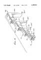
- Provision for L-shape of the connectors, with progressively elongated stand-off mounts,facilitates their closely stacked relation as described, which in turn saves circuit board space for other connectors.
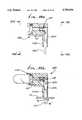
- FIG. 1is a perspective view of multiple connectors which are interconnected and stacked, and showing progressively elongated stand-off mounts;
- FIG. 2is a vertical section taken through the FIG. 1 stacked multiple connectors
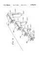
- FIG. 3is a view like FIG. 1, but showing the multiple connectors in alignment, but separated condition, the lower ends of the connectors adapted for surface mounting on a circuit board;
- FIG. 4is a view like FIG. 3, but with modified lower ends of the connector adapting through hole socket mounting;
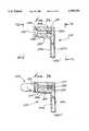
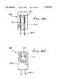
- FIG. 5(a)is a vertical section taken through the smallest connector shown in FIG. 3;
- FIG. 5(b)is a view like FIG. 5(a) showing a light unit attached
- FIG. 5(c)is a right end elevational view taken on lines 5(c)--5(c) of FIG. 5(a);
- FIG. 5 (d)is a left end view taken on lines 5(d)--5(d) in FIG. 5(a);
- FIG. 6(a)is a view like FIG. 5(a), but showing the next in sequence connector of FIG. 3;
- FIGS. 6(b)-6(d)are views like FIGS. 5(b)-5(d), but showing the FIG. 6(a) connector;
- FIG. 7(a)is a view like FIG. 6(a), but showing the next in sequence larger connector of FIG. 3;
- FIGS. 7(b)-7(d)are views like FIGS. 6(b)-6(d), but showing the FIG. 7(a) connector;
- FIG. 8(a)is a view like FIG. 7(a), but showing the next in sequence larger connector of FIG. 3;
- FIGS. 8(b)-8(d)are views like FIGS. 7(b)-7(d), but showing the FIG. 8(a) connector;
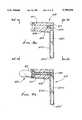
- FIG. 9(a)is a vertical section taken through the smallest connector shown in FIG. 4;
- FIG. 9(b)is view like FIG. 9(a), but showing a light unit attached;
- FIG. 9(c)is a right end view taken on lines 9(c)--9(c) FIG. 9 (a);
- FIG. 9(d)is a left end view taken on lines 9(d)--9(d) of FIG. 9(a);
- FIG. 10(a)is a view like FIG. 9(a) but showing the next larger in sequence connector of FIG. 4;
- FIGS. 10(b)-10(d)are views like FIGS. 6(b)-6(d) but showing the FIG. 10(a) connector;
- FIGS. 11(a)-11(d)are views like FIGS. 10(a)-10(d) but showing the next larger in sequence connector of FIG. 4;
- FIGS. 12(a)-12(d)are views like FIGS. 11(a)-11(d) but showing the next larger in sequence connector of FIG. 4;
- FIG. 13(a)is a view like FIG. 10(a) but showing a support leg on a stand-off mount;
- FIG. 13(b)is a view like FIG. 13(a) but showing a light unit attached;
- FIG. 13(c)is a right end elevational view taken on lines 13(c)--13(c) of FIG. 13(a);
- FIG. 13(d)is a left end elevational view taken on lines 13(d)--13(d) of FIG. 13(a);
- FIG. 13(e)is a perspective view of the connector of FIGS. 13(a)-13(d) .
- a connector 10includes a one-piece molded plastic body 11 having a recessed end 12 adapted to serve as a support for a circuit element or component, having terminal means.
- a circuit elementis a light unit such as LED 14.
- the bodydefines a longitudinally horizontally forwardly opening recess 12a to receive the base 15 of the circuit element, as seen in FIG. 5(b).
- Base 15may be circular, for reception within a body cylindrical wall 16.
- a reduced diameter cylindrical wall 17extends between lateral shoulder 18 and a body rear wall 19.
- Rear wall 19defines through opening means 19a to receive insertion of rod-like terminal means 20 projecting rearwardly from the base 15 of the circuit element.
- the through opening means 19amay accommodate different configurations or groupings of circuit element terminals, while also accommodating retention of such terminals as by terminal structure 21.
- the latterincludes two terminal sockets 21a in circularly or bent condition and each having three inwardly deformed spring fingers 21b spaced about a horizontal axis to slidably receive a rod-like terminal 20. Accordingly, effective bent terminal retention or captivating means is provided for ease of retention and electrical contact with the rod-like terminals 20, i.e. the rearward extent of the terminal means.
- the terminal structure 21also extends vertically downwardly at 21c relative to the socket 21a for electrical connection with circuitry associated with a circuit board. See FIGS. 1 and 2 the lower end of 21c, bent laterally at 21c' for electrical connection to wave solder or other connection 100 electrically connected at 101 to circuit board circuitry. Bend or foot 21c' also serves to support the body 11, when soldered to 100. Molded plastic body 11 forms a stand-off support or mount at 11a extending downwardly about the terminal structure 21c. Accordingly, such terminal structure 21 has L-shaped configuration (i.e. legs 21a and 21c), and the stand-off mount also has L-shaped configuration, such L-shape having been pre-formed for stability and simplicity.
- FIGS. 6(a)-6(d)illustrate a closely similar connector 110 including a one-piece, L-shaped, molded plastic body 111 having a recessed end 112 to serve as a support for a circuit element component, having terminal means. See for example light unit such as LED 114.
- Elements of the connector the same as those of FIGS. 5(a)-(d)bear the same identifying numerals, with a numeral "1" preceding the remainder of the numeral.
- the terminal structure 121extends downwardly at 121c to greater extent than structure 21c. This is to enable mounting of 110 on 10 to extend above 11 and also downwardly rearwardly of 11a. See FIG. 2.
- Feet 121c'extend horizontally oppositely, in the same horizontal plane as feet 21c' to connect to circuitry 200 on the circuit board.
- interconnect meansto enable slidable interconnection of 10 and 110, as in the direction of arrow 50, in FIG. 2, whereby the connectors are stacked vertically, in piggy-back relation.
- interconnect meansincludes tongue and groove elements that extend forwardly and horizontally. See for example dovetail groove 51 sunk in the top wall 52 of 10, to intersect rear wall 19, and the mating dovetail tongue 153 protruding downwardly from the lower wall 154 of 110, as shown in FIGS. 5(a) and 6(a). Interengaged stop shoulders are shown at 55 and 156, to limit sliding interconnection in direction 50.
- the form of the invention seen in FIGS. 1-6may be regarded as preferred; however, other forms as described below, are also desirable.
- FIGS. 7(a)-7(b)illustrate another closely similar connector 210, including a one-piece, L-shaped, molded plastic body 211, having a recessed end 212 to serve as a support for a circuit element or component, having tensional means. See for example light unit such as LED 214.
- Elements of the connector the same as those of FIGS. 5(a)-5(d)bear the same illustrated numerals with a numeral "2" preceding the remainder of the numeral.
- the terminal structure 221extends downwardly at 221c to greater extent than structures 21c and 121c. This is to enable mounting of 211 on 111 to extend above 11, and above 111, and also downwardly rearwardly of 111a. See FIG. 2.
- interconnect meansto enable slidable interconnection of 110 and 210, as in direction 50, whereby the connectors are stacked vertically or perpendicularly relative to the circuit board in piggy-back relation.
- interconnect meansinclude tongue and groove elements, that extend forwardly and horizontally, parallel to the circuit board. See for example dovetail groove 151 sunk in the top wall 152 of 110, to intersect rear wall 19, and the mating dovetailed tongue 253 that protrudes downwardly from the lower wall 254 of 210, as shown in FIGS. 7(a) and 7(b). Interengaged stop shoulders are shown at 155 and 256, to limit sliding interconnection in direction 50.
- FIGS. 9(a)-9(d) and FIG. 4illustrate a connector 400 like connector 10 in all respects, and bearing corresponding identification numerals, except as to the lower ends of the terminal structure 21c.
- Such lower ends at 21c"extend straight down, to pass through openings 70 in the circuit board 71, and to connect to circuitry 72 (such as wave solder) below the board.
- FIGS. 10(a)-10(d) and FIG. 4illustrate a connector 500 like connector 110 in all respects, and bearing corresponding numerals, except that the lower ends 121c" of the terminal structure 121c extend straight down, in perpendicular relation to the circuit board 71 to pass through openings 70 therein and connect to circuitry 72 (or 72' if different from 72), below the board.
- FIGS. 11(a)-11(d) and FIG. 4illustrate a connector 600 like connector 210 in all respects, and bearing corresponding numerals, except that the lower ends 221c" of the terminal structure 221c extend straight down to pass through openings 70 in the circuit board and connect to circuitry 72 (or 72" if different from 72 or 72') below the board.
- FIGS. 12(a)-12(d) and FIG. 4illustrate a connector 700 like connector 310 in all respects, and bearing corresponding numerals, except that the lower ends 321c" of the terminal structure 321c extend straight down to pass through openings 70 in the circuit board, and connect to circuitry 72 (or 72'" if different from 72 or 72' or 72") below the board.
- FIGS. 13(a)-13(e)show a structure 800 like that of FIGS. 10(a)-10(d), except for the added provision of two support legs or pins 820 that project downwardly from the lower end of the stand-off mount, to extend into holes 82, in the circuit board 182, providing additional support.
- Pins 820may be molded integrally with the molded plastic stand-off 811a of the connector, to project downwardly, near the lower ends 821c" of the terminal structure down-leg or legs 821c.
Landscapes
- Coupling Device And Connection With Printed Circuit (AREA)
Abstract
Description
Claims (7)
Priority Applications (1)
| Application Number | Priority Date | Filing Date | Title |
|---|---|---|---|
| US08/606,012US5709554A (en) | 1996-02-12 | 1996-02-12 | Angled circuit connector structure |
Applications Claiming Priority (1)
| Application Number | Priority Date | Filing Date | Title |
|---|---|---|---|
| US08/606,012US5709554A (en) | 1996-02-12 | 1996-02-12 | Angled circuit connector structure |
Publications (1)
| Publication Number | Publication Date |
|---|---|
| US5709554Atrue US5709554A (en) | 1998-01-20 |
Family
ID=24426137
Family Applications (1)
| Application Number | Title | Priority Date | Filing Date |
|---|---|---|---|
| US08/606,012Expired - LifetimeUS5709554A (en) | 1996-02-12 | 1996-02-12 | Angled circuit connector structure |
Country Status (1)
| Country | Link |
|---|---|
| US (1) | US5709554A (en) |
Cited By (34)
| Publication number | Priority date | Publication date | Assignee | Title |
|---|---|---|---|---|
| USD409576S (en)* | 1998-04-12 | 1999-05-11 | Elcon Products International | Electrical connector housing |
| US5951152A (en)* | 1997-06-17 | 1999-09-14 | Lumex, Inc. | Light source housing apparatus and method of manufacture |
| USD417862S (en) | 1999-01-12 | 1999-12-21 | Elcon Products International | Electrical connector housing |
| USD421419S (en)* | 1998-09-04 | 2000-03-07 | Hon Hai Precision Ind. Co., Ltd. | Stacked connector assembly |
| US6093060A (en)* | 1999-03-11 | 2000-07-25 | The Whitaker Corporation | Electrical connector assembled with a terminal array that is connected by a carrier strip |
| US6099349A (en)* | 1999-02-23 | 2000-08-08 | Amphenol Corporation | Dual multiport RJ connector arrangement |
| US6126481A (en)* | 1998-09-04 | 2000-10-03 | Hon Hai Precision Ind. Co., Ltd. | Stacked connection device |
| US6149459A (en)* | 1999-11-01 | 2000-11-21 | Hon Hai Precision Ind. Co., Ltd. | Stacked electrical connector assembly |
| US6170963B1 (en)* | 1998-03-30 | 2001-01-09 | Eastman Kodak Company | Light source |
| US6179653B1 (en)* | 2000-03-23 | 2001-01-30 | Simula Co. Ltd. | Stacking computer connector |
| US6210214B1 (en)* | 1999-12-21 | 2001-04-03 | Hon Hai Precision Ind. Co., Ltd. | Stacked modular jack connector assembly |
| US6227905B1 (en)* | 1999-12-03 | 2001-05-08 | Hon Hai Precision Ind. Co., Ltd. | Receptacle electrical connector assembly |
| US6234834B1 (en)* | 1999-12-17 | 2001-05-22 | Hon Hai Precision Ind. Co., Ltd. | Stacked electrical connector assembly |
| US6234833B1 (en)* | 1999-12-03 | 2001-05-22 | Hon Hai Precision Ind. Co., Ltd. | Receptacle electrical connector assembly |
| US6238241B1 (en)* | 1999-12-27 | 2001-05-29 | Hon Hai Precision Ind. Co., Ltd. | Stacked electrical connector assembly |
| US6250958B1 (en)* | 2000-02-25 | 2001-06-26 | Chunt-Iong Hsish | Modular electrical connector with enhanced antielectromagnetic interference performance |
| US6261124B1 (en)* | 1997-09-25 | 2001-07-17 | Deltron Components Limited | Connectors |
| US6394816B1 (en)* | 1999-10-01 | 2002-05-28 | Yazaki Corporation | Connecting device for flat circuit |
| US6524130B1 (en)* | 2002-06-03 | 2003-02-25 | Hon Hai Precision Ind. Co., Ltd. | Electrical connector assembly |
| US6555746B2 (en)* | 2001-08-24 | 2003-04-29 | Intel Corporation | Horizontal component retention socket |
| US20040180574A1 (en)* | 2003-03-11 | 2004-09-16 | Richard Liu | Stacked connector assembly |
| US20040248464A1 (en)* | 2003-06-06 | 2004-12-09 | Zhenglan Xue | Stacked electrical connector assembly |
| US20050153598A1 (en)* | 2004-01-14 | 2005-07-14 | Meister Douglas L. | Connector assembly |
| US20060223366A1 (en)* | 2005-03-30 | 2006-10-05 | Fujitsu Limited | Connector mounting structure |
| US20070063323A1 (en)* | 2005-09-21 | 2007-03-22 | Taiwan Oasis Technology Co., Ltd. | LED positioning structure |
| US20090146561A1 (en)* | 2007-12-11 | 2009-06-11 | Foxsemicon Integrated Technology, Inc. | Solid state illumination device |
| US20100062638A1 (en)* | 2007-10-08 | 2010-03-11 | Winchester Electronics Corporation | Modular interconnect apparatus |
| EP2182587A1 (en)* | 2008-11-04 | 2010-05-05 | Everlight Electronics Co., Ltd. | Connector and light source apparatus |
| US20100109501A1 (en)* | 2008-11-04 | 2010-05-06 | Everlight Electronics Co., Ltd. | Connector and light source apparatus |
| US20100110685A1 (en)* | 2008-11-04 | 2010-05-06 | Everlight Electronics Co., Ltd. | Light tube |
| US20100135022A1 (en)* | 2003-05-01 | 2010-06-03 | Kevin Raymond Deguara | Lighting substrate |
| US20100259943A1 (en)* | 2009-04-14 | 2010-10-14 | Phoseon Technology, Inc. | Modular light source |
| CN110197971A (en)* | 2018-02-26 | 2019-09-03 | 中航光电科技股份有限公司 | Contact assembly and osculating element, connector with the contact assembly |
| CN116313610A (en)* | 2023-03-22 | 2023-06-23 | 温州市麦特力克电器有限公司 | Wall switch, socket and combination thereof |
Citations (21)
| Publication number | Priority date | Publication date | Assignee | Title |
|---|---|---|---|---|
| US3887803A (en)* | 1974-05-28 | 1975-06-03 | Savage John Jun | Light emitting diode device |
| US4035681A (en)* | 1975-12-22 | 1977-07-12 | Savage John Jun | Polygonal lens |
| US4065198A (en)* | 1976-12-13 | 1977-12-27 | Wescom, Inc. | LED Mounting retainer and display |
| US4195330A (en)* | 1975-12-08 | 1980-03-25 | Savage John Jun | Lens clip and cap for led or light unit assembly |
| US4398240A (en)* | 1978-05-19 | 1983-08-09 | Savage John Jun | Lens cap holder for attachment to circuit boards |
| US4402110A (en)* | 1979-07-16 | 1983-09-06 | Savage John Jun | Lens cap holder for attachment to circuit boards having a plastic inverted U-shaped hinge |
| US4423465A (en)* | 1981-09-30 | 1983-12-27 | Teng Ching Weng | Combination electronic circuit element with multidirectionally adjustable joints |
| US4425018A (en)* | 1980-04-17 | 1984-01-10 | C.A. Weidmuller Gmbh & Co. | Modular electrical plug and socket connectors |
| US4471414A (en)* | 1982-03-11 | 1984-09-11 | Savage John Jun | Integrated light unit and circuit element attachable to circuit board |
| US4491900A (en)* | 1982-09-27 | 1985-01-01 | Savage John Jun | Lens and mount for use with electromagnetic wave source |
| US4583807A (en)* | 1983-12-13 | 1986-04-22 | Amp Incorporated | Surface mount connector |
| US4612602A (en)* | 1983-12-03 | 1986-09-16 | Mentor Ing. Dr. Paul Mozar | Front plate mounting group for a printed circuit board |
| US4667277A (en)* | 1985-09-20 | 1987-05-19 | General Instrument Corporation | Indicator lamp assembly |
| US4674008A (en)* | 1984-12-25 | 1987-06-16 | Alps Electric Co., Ltd. | Display element attachment holder |
| US4676565A (en)* | 1984-10-12 | 1987-06-30 | Allied Corporation | Connector adapted to be mounted on a surface of a printed circuit board |
| US4727648A (en)* | 1985-04-22 | 1988-03-01 | Savage John Jun | Circuit component mount and assembly |
| US4790763A (en)* | 1986-04-22 | 1988-12-13 | Amp Incorporated | Programmable modular connector assembly |
| US4837927A (en)* | 1985-04-22 | 1989-06-13 | Savage John Jun | Method of mounting circuit component to a circuit board |
| US4897769A (en)* | 1988-05-18 | 1990-01-30 | Xerox Corporation | Right angle light emitting diode assembly with snap-in feature |
| US5116229A (en)* | 1990-12-17 | 1992-05-26 | Savage John Jun | Light unit terminals maintained in bent condition |
| EP0555933A1 (en)* | 1992-02-14 | 1993-08-18 | Berg Electronics Manufacturing B.V. | Coaxial connector module for mounting on a printed circuit board |
- 1996
- 1996-02-12USUS08/606,012patent/US5709554A/ennot_activeExpired - Lifetime
Patent Citations (21)
| Publication number | Priority date | Publication date | Assignee | Title |
|---|---|---|---|---|
| US3887803A (en)* | 1974-05-28 | 1975-06-03 | Savage John Jun | Light emitting diode device |
| US4195330A (en)* | 1975-12-08 | 1980-03-25 | Savage John Jun | Lens clip and cap for led or light unit assembly |
| US4035681A (en)* | 1975-12-22 | 1977-07-12 | Savage John Jun | Polygonal lens |
| US4065198A (en)* | 1976-12-13 | 1977-12-27 | Wescom, Inc. | LED Mounting retainer and display |
| US4398240A (en)* | 1978-05-19 | 1983-08-09 | Savage John Jun | Lens cap holder for attachment to circuit boards |
| US4402110A (en)* | 1979-07-16 | 1983-09-06 | Savage John Jun | Lens cap holder for attachment to circuit boards having a plastic inverted U-shaped hinge |
| US4425018A (en)* | 1980-04-17 | 1984-01-10 | C.A. Weidmuller Gmbh & Co. | Modular electrical plug and socket connectors |
| US4423465A (en)* | 1981-09-30 | 1983-12-27 | Teng Ching Weng | Combination electronic circuit element with multidirectionally adjustable joints |
| US4471414A (en)* | 1982-03-11 | 1984-09-11 | Savage John Jun | Integrated light unit and circuit element attachable to circuit board |
| US4491900A (en)* | 1982-09-27 | 1985-01-01 | Savage John Jun | Lens and mount for use with electromagnetic wave source |
| US4612602A (en)* | 1983-12-03 | 1986-09-16 | Mentor Ing. Dr. Paul Mozar | Front plate mounting group for a printed circuit board |
| US4583807A (en)* | 1983-12-13 | 1986-04-22 | Amp Incorporated | Surface mount connector |
| US4676565A (en)* | 1984-10-12 | 1987-06-30 | Allied Corporation | Connector adapted to be mounted on a surface of a printed circuit board |
| US4674008A (en)* | 1984-12-25 | 1987-06-16 | Alps Electric Co., Ltd. | Display element attachment holder |
| US4727648A (en)* | 1985-04-22 | 1988-03-01 | Savage John Jun | Circuit component mount and assembly |
| US4837927A (en)* | 1985-04-22 | 1989-06-13 | Savage John Jun | Method of mounting circuit component to a circuit board |
| US4667277A (en)* | 1985-09-20 | 1987-05-19 | General Instrument Corporation | Indicator lamp assembly |
| US4790763A (en)* | 1986-04-22 | 1988-12-13 | Amp Incorporated | Programmable modular connector assembly |
| US4897769A (en)* | 1988-05-18 | 1990-01-30 | Xerox Corporation | Right angle light emitting diode assembly with snap-in feature |
| US5116229A (en)* | 1990-12-17 | 1992-05-26 | Savage John Jun | Light unit terminals maintained in bent condition |
| EP0555933A1 (en)* | 1992-02-14 | 1993-08-18 | Berg Electronics Manufacturing B.V. | Coaxial connector module for mounting on a printed circuit board |
Cited By (48)
| Publication number | Priority date | Publication date | Assignee | Title |
|---|---|---|---|---|
| US5951152A (en)* | 1997-06-17 | 1999-09-14 | Lumex, Inc. | Light source housing apparatus and method of manufacture |
| US6261124B1 (en)* | 1997-09-25 | 2001-07-17 | Deltron Components Limited | Connectors |
| US6170963B1 (en)* | 1998-03-30 | 2001-01-09 | Eastman Kodak Company | Light source |
| USD409576S (en)* | 1998-04-12 | 1999-05-11 | Elcon Products International | Electrical connector housing |
| USD421419S (en)* | 1998-09-04 | 2000-03-07 | Hon Hai Precision Ind. Co., Ltd. | Stacked connector assembly |
| US6126481A (en)* | 1998-09-04 | 2000-10-03 | Hon Hai Precision Ind. Co., Ltd. | Stacked connection device |
| USD417862S (en) | 1999-01-12 | 1999-12-21 | Elcon Products International | Electrical connector housing |
| US6244896B1 (en) | 1999-02-23 | 2001-06-12 | Amphenol Corporation | Dual multiport RJ connector arrangement |
| US6099349A (en)* | 1999-02-23 | 2000-08-08 | Amphenol Corporation | Dual multiport RJ connector arrangement |
| EP1032092A3 (en)* | 1999-02-23 | 2003-10-15 | Amphenol Corporation | Dual multiport RJ connector arrangement |
| US6093060A (en)* | 1999-03-11 | 2000-07-25 | The Whitaker Corporation | Electrical connector assembled with a terminal array that is connected by a carrier strip |
| US6394816B1 (en)* | 1999-10-01 | 2002-05-28 | Yazaki Corporation | Connecting device for flat circuit |
| US6149459A (en)* | 1999-11-01 | 2000-11-21 | Hon Hai Precision Ind. Co., Ltd. | Stacked electrical connector assembly |
| US6234833B1 (en)* | 1999-12-03 | 2001-05-22 | Hon Hai Precision Ind. Co., Ltd. | Receptacle electrical connector assembly |
| US6227905B1 (en)* | 1999-12-03 | 2001-05-08 | Hon Hai Precision Ind. Co., Ltd. | Receptacle electrical connector assembly |
| US6234834B1 (en)* | 1999-12-17 | 2001-05-22 | Hon Hai Precision Ind. Co., Ltd. | Stacked electrical connector assembly |
| US6210214B1 (en)* | 1999-12-21 | 2001-04-03 | Hon Hai Precision Ind. Co., Ltd. | Stacked modular jack connector assembly |
| US6238241B1 (en)* | 1999-12-27 | 2001-05-29 | Hon Hai Precision Ind. Co., Ltd. | Stacked electrical connector assembly |
| US6250958B1 (en)* | 2000-02-25 | 2001-06-26 | Chunt-Iong Hsish | Modular electrical connector with enhanced antielectromagnetic interference performance |
| US6179653B1 (en)* | 2000-03-23 | 2001-01-30 | Simula Co. Ltd. | Stacking computer connector |
| US6555746B2 (en)* | 2001-08-24 | 2003-04-29 | Intel Corporation | Horizontal component retention socket |
| US6524130B1 (en)* | 2002-06-03 | 2003-02-25 | Hon Hai Precision Ind. Co., Ltd. | Electrical connector assembly |
| US20040180574A1 (en)* | 2003-03-11 | 2004-09-16 | Richard Liu | Stacked connector assembly |
| US20100135022A1 (en)* | 2003-05-01 | 2010-06-03 | Kevin Raymond Deguara | Lighting substrate |
| US20040248464A1 (en)* | 2003-06-06 | 2004-12-09 | Zhenglan Xue | Stacked electrical connector assembly |
| US7008261B2 (en) | 2003-06-06 | 2006-03-07 | Hon Hai Precision Ind. Co., Ltd. | Stacked electrical connector assembly |
| US20050153598A1 (en)* | 2004-01-14 | 2005-07-14 | Meister Douglas L. | Connector assembly |
| US20060223366A1 (en)* | 2005-03-30 | 2006-10-05 | Fujitsu Limited | Connector mounting structure |
| US20090053919A1 (en)* | 2005-03-30 | 2009-02-26 | Fujitsu Limited | Connector mounting structure |
| US7322736B2 (en)* | 2005-09-21 | 2008-01-29 | Taiwan Oasis Technology Co., Ltd. | LED positioning structure |
| US20070063323A1 (en)* | 2005-09-21 | 2007-03-22 | Taiwan Oasis Technology Co., Ltd. | LED positioning structure |
| US8157572B2 (en) | 2007-10-08 | 2012-04-17 | Winchester Electronics Corporation | Modular interconnect apparatus |
| US20100062638A1 (en)* | 2007-10-08 | 2010-03-11 | Winchester Electronics Corporation | Modular interconnect apparatus |
| US7896656B2 (en)* | 2007-10-08 | 2011-03-01 | Winchester Electronics Corporation | Modular interconnect apparatus |
| US20110217871A1 (en)* | 2007-10-08 | 2011-09-08 | Winchester Electronics Corporation | Modular interconnect apparatus |
| US20090146561A1 (en)* | 2007-12-11 | 2009-06-11 | Foxsemicon Integrated Technology, Inc. | Solid state illumination device |
| US8556454B2 (en) | 2008-11-04 | 2013-10-15 | Everlight Electronics Co., Ltd. | Light tube |
| US20100109501A1 (en)* | 2008-11-04 | 2010-05-06 | Everlight Electronics Co., Ltd. | Connector and light source apparatus |
| US20100110685A1 (en)* | 2008-11-04 | 2010-05-06 | Everlight Electronics Co., Ltd. | Light tube |
| EP2182587A1 (en)* | 2008-11-04 | 2010-05-05 | Everlight Electronics Co., Ltd. | Connector and light source apparatus |
| US7896701B2 (en) | 2008-11-04 | 2011-03-01 | Everlight Electronics Co., Ltd. | Connector and light source apparatus |
| US20110097944A1 (en)* | 2008-11-04 | 2011-04-28 | Everlight Electronics Co., Ltd | Connector and Light Source Apparatus |
| US7988492B2 (en) | 2008-11-04 | 2011-08-02 | Everlight Electronics Co., Ltd. | Connector and light source apparatus |
| US20100259943A1 (en)* | 2009-04-14 | 2010-10-14 | Phoseon Technology, Inc. | Modular light source |
| US8678612B2 (en)* | 2009-04-14 | 2014-03-25 | Phoseon Technology, Inc. | Modular light source |
| CN110197971A (en)* | 2018-02-26 | 2019-09-03 | 中航光电科技股份有限公司 | Contact assembly and osculating element, connector with the contact assembly |
| CN110197971B (en)* | 2018-02-26 | 2021-07-30 | 中航光电科技股份有限公司 | Contact assembly, contact unit and connector having the same |
| CN116313610A (en)* | 2023-03-22 | 2023-06-23 | 温州市麦特力克电器有限公司 | Wall switch, socket and combination thereof |
Similar Documents
| Publication | Publication Date | Title |
|---|---|---|
| US5709554A (en) | Angled circuit connector structure | |
| US7367816B2 (en) | Board-to-board connectors | |
| US5145384A (en) | Electrical connector and terminal therefor | |
| US6712641B2 (en) | Resilient contact and assembly thereof | |
| US7081017B2 (en) | USB electrical connector | |
| USRE41473E1 (en) | Board-to-board electrical connector assembly | |
| US6224417B1 (en) | Assembly containing a modular jack and a light emitting diode | |
| US5203716A (en) | Terminal block for printed circuit boards | |
| US6210218B1 (en) | Electrical connector | |
| US7591690B1 (en) | Connecting device for solar panel | |
| US20070072488A1 (en) | Audio jack connector with reliable grounding device | |
| KR101115826B1 (en) | Connection terminal | |
| EP0104013A1 (en) | Multi-contact electrical connector | |
| US6080008A (en) | Push-wire contact | |
| US20090291581A1 (en) | Electrical connector assembly for miniaturization | |
| US20070243744A1 (en) | Electrical connector | |
| US20030166348A1 (en) | Contact guide retention apparatus | |
| US20070155227A1 (en) | Electrical connector | |
| US20160156117A1 (en) | Card edge connector with locking device | |
| EP1166400B1 (en) | Electrical connector | |
| JP2004513490A (en) | Microelectronics connector with open cavity insert | |
| US7125280B1 (en) | Electrical connector assembly | |
| JPH07326450A (en) | Socket and manufacturing method thereof | |
| US20060246783A1 (en) | Electrical connector assembly | |
| US6863542B2 (en) | Interconnecting structure for electrically connecting two printed circuit boards |
Legal Events
| Date | Code | Title | Description |
|---|---|---|---|
| STCF | Information on status: patent grant | Free format text:PATENTED CASE | |
| REMI | Maintenance fee reminder mailed | ||
| FPAY | Fee payment | Year of fee payment:4 | |
| SULP | Surcharge for late payment | ||
| FPAY | Fee payment | Year of fee payment:8 | |
| AS | Assignment | Owner name:SAVAGE, RONALD, TRUSTEE FOR JOHN SAVAGE LIVING TRU Free format text:ASSIGNMENT OF ASSIGNORS INTEREST;ASSIGNOR:SAVAGE, JR., JOHN M.;REEL/FRAME:018866/0880 Effective date:20040802 | |
| AS | Assignment | Owner name:SAVAGE CHARITABLE FOUNDATION, CALIFORNIA Free format text:ASSIGNMENT OF ASSIGNORS INTEREST;ASSIGNORS:ROBERTS, SAMUEL, CO-TRUSTEE OF JOHN SAVAGE LIVING TRUST;SAVAGE, RONALD, CO-TRUSTEE OF JOHN SAVAGE LIVING TRUST;REEL/FRAME:019204/0360;SIGNING DATES FROM 20070406 TO 20070410 | |
| FPAY | Fee payment | Year of fee payment:12 | |
| AS | Assignment | Owner name:TALL TOWER LED, LLC, CALIFORNIA Free format text:SECURITY AGREEMENT;ASSIGNOR:SAVAGE CHARITABLE FOUNDATION;REEL/FRAME:026377/0040 Effective date:20110511 Owner name:VISUAL COMMUNICATIONS COMPANY, INC., CALIFORNIA Free format text:SECURITY AGREEMENT;ASSIGNOR:SAVAGE CHARITABLE FOUNDATION;REEL/FRAME:026377/0040 Effective date:20110511 | |
| AS | Assignment | Owner name:TALL TOWER LED, LLC, CALIFORNIA Free format text:ASSIGNMENT OF ASSIGNORS INTEREST;ASSIGNOR:SAVAGE CHARITABLE FOUNDATION;REEL/FRAME:029346/0531 Effective date:20110511 |