US5708705A - Wallhung arrangement for a cordless telephone - Google Patents
Wallhung arrangement for a cordless telephoneDownload PDFInfo
- Publication number
- US5708705A US5708705AUS08/430,530US43053095AUS5708705AUS 5708705 AUS5708705 AUS 5708705AUS 43053095 AUS43053095 AUS 43053095AUS 5708705 AUS5708705 AUS 5708705A
- Authority
- US
- United States
- Prior art keywords
- connecting unit
- outlet
- implement
- wiring implement
- wiring
- Prior art date
- Legal status (The legal status is an assumption and is not a legal conclusion. Google has not performed a legal analysis and makes no representation as to the accuracy of the status listed.)
- Expired - Fee Related
Links
Images

Classifications
- H—ELECTRICITY
- H04—ELECTRIC COMMUNICATION TECHNIQUE
- H04M—TELEPHONIC COMMUNICATION
- H04M1/00—Substation equipment, e.g. for use by subscribers
- H04M1/72—Mobile telephones; Cordless telephones, i.e. devices for establishing wireless links to base stations without route selection
- H04M1/725—Cordless telephones
- H—ELECTRICITY
- H01—ELECTRIC ELEMENTS
- H01R—ELECTRICALLY-CONDUCTIVE CONNECTIONS; STRUCTURAL ASSOCIATIONS OF A PLURALITY OF MUTUALLY-INSULATED ELECTRICAL CONNECTING ELEMENTS; COUPLING DEVICES; CURRENT COLLECTORS
- H01R13/00—Details of coupling devices of the kinds covered by groups H01R12/70 or H01R24/00 - H01R33/00
- H01R13/62—Means for facilitating engagement or disengagement of coupling parts or for holding them in engagement
- H01R13/639—Additional means for holding or locking coupling parts together, after engagement, e.g. separate keylock, retainer strap
- H01R13/6395—Additional means for holding or locking coupling parts together, after engagement, e.g. separate keylock, retainer strap for wall or panel outlets
- H—ELECTRICITY
- H01—ELECTRIC ELEMENTS
- H01R—ELECTRICALLY-CONDUCTIVE CONNECTIONS; STRUCTURAL ASSOCIATIONS OF A PLURALITY OF MUTUALLY-INSULATED ELECTRICAL CONNECTING ELEMENTS; COUPLING DEVICES; CURRENT COLLECTORS
- H01R24/00—Two-part coupling devices, or either of their cooperating parts, characterised by their overall structure
- H01R24/66—Two-part coupling devices, or either of their cooperating parts, characterised by their overall structure with pins, blades or analogous contacts and secured to apparatus or structure, e.g. to a wall
- H01R24/68—Two-part coupling devices, or either of their cooperating parts, characterised by their overall structure with pins, blades or analogous contacts and secured to apparatus or structure, e.g. to a wall mounted on directly pluggable apparatus
- H—ELECTRICITY
- H01—ELECTRIC ELEMENTS
- H01R—ELECTRICALLY-CONDUCTIVE CONNECTIONS; STRUCTURAL ASSOCIATIONS OF A PLURALITY OF MUTUALLY-INSULATED ELECTRICAL CONNECTING ELEMENTS; COUPLING DEVICES; CURRENT COLLECTORS
- H01R27/00—Coupling parts adapted for co-operation with two or more dissimilar counterparts
- H01R27/02—Coupling parts adapted for co-operation with two or more dissimilar counterparts for simultaneous co-operation with two or more dissimilar counterparts
- H—ELECTRICITY
- H02—GENERATION; CONVERSION OR DISTRIBUTION OF ELECTRIC POWER
- H02G—INSTALLATION OF ELECTRIC CABLES OR LINES, OR OF COMBINED OPTICAL AND ELECTRIC CABLES OR LINES
- H02G3/00—Installations of electric cables or lines or protective tubing therefor in or on buildings, equivalent structures or vehicles
- H02G3/02—Details
- H02G3/08—Distribution boxes; Connection or junction boxes
- H02G3/12—Distribution boxes; Connection or junction boxes for flush mounting
- H02G3/123—Distribution boxes; Connection or junction boxes for flush mounting in thin walls
- H—ELECTRICITY
- H04—ELECTRIC COMMUNICATION TECHNIQUE
- H04M—TELEPHONIC COMMUNICATION
- H04M1/00—Substation equipment, e.g. for use by subscribers
- H04M1/02—Constructional features of telephone sets
- H04M1/0293—Terminal boxes for telephone sets
- H—ELECTRICITY
- H01—ELECTRIC ELEMENTS
- H01R—ELECTRICALLY-CONDUCTIVE CONNECTIONS; STRUCTURAL ASSOCIATIONS OF A PLURALITY OF MUTUALLY-INSULATED ELECTRICAL CONNECTING ELEMENTS; COUPLING DEVICES; CURRENT COLLECTORS
- H01R2103/00—Two poles
Definitions
- the present inventionrelates to a cordless telephone and, more particularly, to a method and structure for mounting a connecting unit for a cordless telephone on a wall.
- cordless telephoneshave recently been put on the market and extensively used even in homes.
- One of themhas a connecting device connected to a telephone circuit, and a cordless transmitter/receiver.
- the connecting deviceis supplied with power via an AC adapter and a connecting cord and is connected to an indoor telephone line connector by a connection code and a cable.
- the connecting deviceis connected to the outlet of a commercially available power source and a telephone line connector by a connection cord and a cable, respectively.
- Such a configurationmakes the cord arrangement troublesome and unsightly.
- the location available for the connecting deviceis limited, depending on the locations of the outlet and connector. Hence, a special rack for mounting the connecting device is often required.
- Japanese Utility Model Laid-Open Publication No. 4-128463discloses a structure in which a connecting unit, having an AC power source connector and a modular jack, is connected to a facsimile apparatus.
- This kind of approachcannot eliminate the troublesome and unsightly cord arrangement because a connection cord extends between the facsimile body and the connecting unit.
- the structureincludes a box having a DC power source adapter and a modular jack and buried in a wall. Part of the terminals of the modular jack is connected to a self-sustaining power source.
- a problem with this schemeis that a commercially available cordless telephone is not usable due to such a special configuration.
- Another problemis that because the box must be buried by a qualified person at the time of building, the structure cannot be freely laid out and is awkward to use.
- Japanese Utility Model Laid-Open Publication No. 4-20746proposes a telephone outlet with a power source.
- the telephone outlethas a modular jack whose opposite outermost terminals are used as DC power output terminals.
- This kind of schemelike the buried box scheme stated above, prevents a commercially available cordless telephone to be connected to the outlet.
- the outletprotrudes from a wall and constitutes an obstruction.
- an object of the present inventionto provide a method and structure for allowing a connecting unit for a cordless telephone to be mounted on a wall by a simple operation, and a wiring implement and connecting unit therefor.
- a wallhung arrangement for a cordless telephone of the present inventionhas a wiring implement buried in a wall, and a connecting unit for communication.
- the wiring implementhas on the front thereof an outlet for supplying AC power, and at least one modular connector for connecting a communication line.
- the connecting unithas a power supply plug and at least one modular jack at predetermined positions on a rear thereof. The power supply plug and modular jack are respectively connectable to the outlet and modular connector.
- the connecting unitis affixed to the wiring implement by an affixing device.
- the connecting unitTo mount the connecting unit to the wall, it is pressed unit against the wiring implement to thereby insert the power supply plug and modular jack into the outlet and modular connector, respectively, while affixing the connecting unit to the wiring implement.
- the connecting unit having the above configurationcan be easily mounted to the wiring implement buried in a wall.
- the wallhung arrangementdoes not need cords which are undesirable from the appearance standpoint. Only if the wiring implement is buried in a high portion of a wall of a house at the time of construction, a cordless telephone, for example, can be immediately used by having the connecting unit mounted to the wiring implement. This makes it needless to prepare a rack or similar exclusive support for the connecting unit, thereby improving the living environment.
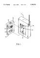
- FIG. 1is a perspective view of a wallhung arrangement for a cordless telephone and embodying the present invention
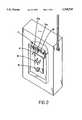
- FIG. 2is a partly taken away perspective view of a connecting unit 1 included in the embodiment
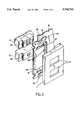
- FIG. 3is an exploded perspective view of a wiring implement also included in the embodiment
- FIG. 4is a fragmentary section showing the embodiment in detail
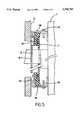
- FIG. 5is a fragmentary section of an alternative embodiment of the present invention.
- FIG. 6is a fragmentary section of another alternative embodiment of the present invention.
- FIG. 1 of the drawingsa wallhung arrangement for a cordless telephone and embodying the present invention is shown.
- the arrangementincludes connecting unit 1 for interchanging signals with a cordless transceiver/receiver, not shown, by a radio wave.
- An AC power supply plug 4 and a modular jack 5are affixed to the rear of the connecting unit 1.
- the modular jack 5is connectable to a telephone circuit which will be described.
- a metal fitting 7is positioned above the plug 4 and constantly biased by a spring which will be described. In this condition, the metal fitting 7 is rotatable in a direction perpendicular to the rear of the connecting unit 1, as indicated by an arrow a in the figure.
- a wiring implementis mounted on a wall 6 and has an AC outlet 2 and a modular connector 3 which correspond in position to the plug 4 and the modular jack 5, respectively.
- the outlet 2 and plug 4supply power to the connecting unit 1 when the latter is connected to the former.
- the modular connector 3 and modular jack 5constitute a telephone circuit when connected to each other.
- a cover 11covers the outlet 2 and connector 3 except for their surfaces to be connected to the connecting unit 1.
- a hook portion 10is provided on the top of the cover 11 and formed with a recess.
- the connecting unit 1is affixed to the wiring implement by having the fitting 7a thereof received in the recess of the hook portion 10.
- the unit 1To mount the connecting unit 1 to the wiring implement, the unit 1 is tilted such that the upper portion thereof approaches the wall 6. After the fitting 7a of the connecting unit 1 has been inserted into the hook portion 10, the unit 1 is bodily urged against the wall 6 while rotating about the fitting 7a. As a result, the plug 4 and jack 5 are inserted into the outlet 2 and connector 3, respectively.
- the rear of the connecting unit 1may be formed with a cavity great enough to receive the entire cover 11.
- FIG. 2shows the connecting unit 1 in detail.
- a hanging portion 7is provided on the upper portion of the rear of the unit 1.
- the hanging portion 7has, in addition to the metal fixture 7a, a resilient pin 8 to which the fitting 7a is affixed, and a support portion 7b to which the pin 8 is affixed at opposite ends thereof.
- the fitting 7aWhen the fitting 7a is engaged with the hook portion 10 of the wiring implement, it moves in the direction a due to the resiliency of the pin 8 and thereby facilitates the attachment of the unit 1.
- the wiring implementhas a frame 9 for affixing the implement to the wall 6 and having a standardized shape and dimensions.
- the hook portion 10 for receiving the fitting 7a of the connecting unit 1is formed at both of the upper and lower ends of the frame 9. Specifically, the upper and lower ends of the frame 9 are each partly cut and raised to form the hook portion 10.
- a plurality of pairs of lugs 12extend toward each other from the inner edges of the frame 9 in order to fix the outlet, or AC power supply connector, 2 and modular connector 3 in their predetermined positions.
- the connectors 2 and 3are each formed with a pair of recesses 12' for mating with the lugs 12.
- a pair of oblong holes 13are formed through the upper and lower portions of the frame 9.
- a burying box, not shown,is affixed to the frame 9 by screws, not shown, passed through the holes 13.
- Threaded holes 14are formed in the hook portions 10 in order to affix the cover 11 to the frame 9.
- holes 15are formed through the frame 9 for receiving metallic pinching members, not shown.
- the cover 11has its thickness reduced in a portion 16 corresponding to the hook portion 10, so that the hook portion 10 can be easily exposed to the outside. Specifically, when a person purchased a cordless telephone set and mounts the connecting unit 1 on the wall, the person removes the thin portion 16 of the cover 11. As a result, the hook portion 10 is exposed to the outside. Then, the person inserts the metal fitting 7a of the connecting unit 1 into the hook portion 10 and moves the entire unit 1 in the manner stated earlier. Two openings 17 are formed through the cover 11 to allow the AC connector 2 and modular connector 3 to appear therethrough.
- the wiring implement having the above configurationis buried in the wall of a house at the time of construction in the same way as wiring implements for ordinary appliances. Specifically, when a house is built, the wiring implement for a cordless telephone is affixed to a wall at a slightly high level above the floor. The wiring implement, located at a high level, is free from obstructions as to the propagation of radio waves and ensures smooth conversation. Further, because the connecting unit 1 has the metal fitting 7a received in the hook portion 10, it is fixed in place more surely than when it is simply placed on a desk. In this condition, the connecting unit 1 is protected even from vibration attributable to, for example, an earthquake. In addition, before the connecting unit 1 is mounted to the wiring implement, a painting, photograph or mirror may be hung on the wall by use of the hook portion 10 for an ornamental purpose, if desired.
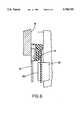
- FIG. 4shows the illustrative embodiment in detail.
- the metal fitting 7a of the connecting unit 1is received in the hook portion 10 of the wiring implement.
- the AC plug 4 and modular jack 5are inserted in the AC outlet 2 and modular connector 3, respectively.
- another metal fitting 7amay be provided on the other end of the rear of the connecting unit 1 and received in the other or lower hook portion 10 of the frame 9.
- FIG. 5An alternative embodiment of the present invention is shown in FIG. 5. As shown, a pair of metal fittings 18 are respectively positioned in the upper and lower portions of the rear of the connecting unit 1. The metal fittings 18 respectively mate with the hook portions 10 of the frame 9. In this embodiment, the AC plug 4 and modular jack 5 are respectively inserted into the AC outlet 2 and modular connector 3. Subsequently, the metal fittings 18 are inserted into the hook portions 10 and fastened to the connecting unit 1 by screws 19.
- FIG. 6shows another alternative embodiment of the present invention.
- an iron plate 20is affixed to the rear of the cover 11.
- a permanent magnet 21is affixed to the rear of the connecting unit 1 at a position corresponding to the iron plate 20.
- the iron plate 20is located at a position where the AC outlet 2 and modular connector 3 are absent.
- the plate 20may be made of a magnetic material other than iron, if desired.
- the frame 9is identical in configuration with standardized frames, it may be safely considered that plugs have a standardized pitch. Hence, only if the dimensions of the hook portion 10 and metal fitting 7a or 18 are standardized, the overall structure can be standardized. This will facilitate the production of equipment by manufacturers in the future and, in addition, allow manufacturers of wiring implements to handle the wiring equipment in the conventional manner.
Landscapes
- Engineering & Computer Science (AREA)
- Signal Processing (AREA)
- Computer Networks & Wireless Communication (AREA)
- Architecture (AREA)
- Civil Engineering (AREA)
- Structural Engineering (AREA)
- Connector Housings Or Holding Contact Members (AREA)
- Telephone Set Structure (AREA)
- Details Of Indoor Wiring (AREA)
Abstract
Description
The present invention relates to a cordless telephone and, more particularly, to a method and structure for mounting a connecting unit for a cordless telephone on a wall.
Various kinds of cordless telephones have recently been put on the market and extensively used even in homes. One of them has a connecting device connected to a telephone circuit, and a cordless transmitter/receiver. The connecting device is supplied with power via an AC adapter and a connecting cord and is connected to an indoor telephone line connector by a connection code and a cable. Specifically, the connecting device is connected to the outlet of a commercially available power source and a telephone line connector by a connection cord and a cable, respectively. Such a configuration, however, makes the cord arrangement troublesome and unsightly. Moreover, the location available for the connecting device is limited, depending on the locations of the outlet and connector. Hence, a special rack for mounting the connecting device is often required.
Various approaches have heretofore been proposed in order to obviated the above problems. For example, Japanese Utility Model Laid-Open Publication No. 4-128463 discloses a structure in which a connecting unit, having an AC power source connector and a modular jack, is connected to a facsimile apparatus. This kind of approach, however, cannot eliminate the troublesome and unsightly cord arrangement because a connection cord extends between the facsimile body and the connecting unit.
Another conventional structure is taught in Japanese Utility Model Laid-Open Publication No. 3-40771. The structure includes a box having a DC power source adapter and a modular jack and buried in a wall. Part of the terminals of the modular jack is connected to a self-sustaining power source. A problem with this scheme is that a commercially available cordless telephone is not usable due to such a special configuration. Another problem is that because the box must be buried by a qualified person at the time of building, the structure cannot be freely laid out and is awkward to use.
Further, Japanese Utility Model Laid-Open Publication No. 4-20746 proposes a telephone outlet with a power source. The telephone outlet has a modular jack whose opposite outermost terminals are used as DC power output terminals. This kind of scheme, like the buried box scheme stated above, prevents a commercially available cordless telephone to be connected to the outlet. In addition, the outlet protrudes from a wall and constitutes an obstruction.
Various standards are prescribed for wallhung AC power source outlets and telephone line connectors which should be built in the walls of houses in the event of construction. It is a common practice for the locations of the outlets and connectors to be determined by assumption beforehand, except for custom-built houses. For example, they are positioned in the vicinity of the corner walls of living rooms and adjacent to the bottoms of such walls, so that both ordinary electric appliances and telephones can be used. However, when a connecting device for a cordless telephone adjoins a floor, it is likely that some obstruction made of metal interferes with radio waves, i.e., conversation. For this reason, the connecting device must be positioned at a high level above the floor. As a result, cords for connecting the connecting device to the power source outlet and telephone line connector should be laid on a wall over a substantial distance. This is undesirable from the appearance viewpoint.
It is, therefore, an object of the present invention to provide a method and structure for allowing a connecting unit for a cordless telephone to be mounted on a wall by a simple operation, and a wiring implement and connecting unit therefor.
A wallhung arrangement for a cordless telephone of the present invention has a wiring implement buried in a wall, and a connecting unit for communication. The wiring implement has on the front thereof an outlet for supplying AC power, and at least one modular connector for connecting a communication line. The connecting unit has a power supply plug and at least one modular jack at predetermined positions on a rear thereof. The power supply plug and modular jack are respectively connectable to the outlet and modular connector. The connecting unit is affixed to the wiring implement by an affixing device.
To mount the connecting unit to the wall, it is pressed unit against the wiring implement to thereby insert the power supply plug and modular jack into the outlet and modular connector, respectively, while affixing the connecting unit to the wiring implement.
The connecting unit having the above configuration can be easily mounted to the wiring implement buried in a wall. The wallhung arrangement does not need cords which are undesirable from the appearance standpoint. Only if the wiring implement is buried in a high portion of a wall of a house at the time of construction, a cordless telephone, for example, can be immediately used by having the connecting unit mounted to the wiring implement. This makes it needless to prepare a rack or similar exclusive support for the connecting unit, thereby improving the living environment.
The above and other objects, features and advantages of the present invention will become apparent from the following detailed description when taken with the accompanying drawings in which:
FIG. 1 is a perspective view of a wallhung arrangement for a cordless telephone and embodying the present invention;
FIG. 2 is a partly taken away perspective view of a connecting unit 1 included in the embodiment;
FIG. 3 is an exploded perspective view of a wiring implement also included in the embodiment;
FIG. 4 is a fragmentary section showing the embodiment in detail;
FIG. 5 is a fragmentary section of an alternative embodiment of the present invention; and
FIG. 6 is a fragmentary section of another alternative embodiment of the present invention.
Referring to FIG. 1 of the drawings, a wallhung arrangement for a cordless telephone and embodying the present invention is shown. As shown, the arrangement includes connecting unit 1 for interchanging signals with a cordless transceiver/receiver, not shown, by a radio wave. An ACpower supply plug 4 and amodular jack 5 are affixed to the rear of the connecting unit 1. Themodular jack 5 is connectable to a telephone circuit which will be described. A metal fitting 7 is positioned above theplug 4 and constantly biased by a spring which will be described. In this condition, the metal fitting 7 is rotatable in a direction perpendicular to the rear of the connecting unit 1, as indicated by an arrow a in the figure.
A wiring implement is mounted on awall 6 and has anAC outlet 2 and amodular connector 3 which correspond in position to theplug 4 and themodular jack 5, respectively. Theoutlet 2 and plug 4 supply power to the connecting unit 1 when the latter is connected to the former. Themodular connector 3 andmodular jack 5 constitute a telephone circuit when connected to each other. Acover 11 covers theoutlet 2 andconnector 3 except for their surfaces to be connected to the connecting unit 1. Ahook portion 10 is provided on the top of thecover 11 and formed with a recess. The connecting unit 1 is affixed to the wiring implement by having the fitting 7a thereof received in the recess of thehook portion 10.
To mount the connecting unit 1 to the wiring implement, the unit 1 is tilted such that the upper portion thereof approaches thewall 6. After the fitting 7a of the connecting unit 1 has been inserted into thehook portion 10, the unit 1 is bodily urged against thewall 6 while rotating about the fitting 7a. As a result, theplug 4 andjack 5 are inserted into theoutlet 2 andconnector 3, respectively.
If desired, the rear of the connecting unit 1 may be formed with a cavity great enough to receive theentire cover 11.
FIG. 2 shows the connecting unit 1 in detail. As shown, a hanging portion 7 is provided on the upper portion of the rear of the unit 1. The hanging portion 7 has, in addition to themetal fixture 7a, aresilient pin 8 to which the fitting 7a is affixed, and asupport portion 7b to which thepin 8 is affixed at opposite ends thereof. When the fitting 7a is engaged with thehook portion 10 of the wiring implement, it moves in the direction a due to the resiliency of thepin 8 and thereby facilitates the attachment of the unit 1.
Referring to FIG. 3, the wiring implement has aframe 9 for affixing the implement to thewall 6 and having a standardized shape and dimensions. Thehook portion 10 for receiving the fitting 7a of the connecting unit 1 is formed at both of the upper and lower ends of theframe 9. Specifically, the upper and lower ends of theframe 9 are each partly cut and raised to form thehook portion 10. A plurality of pairs oflugs 12 extend toward each other from the inner edges of theframe 9 in order to fix the outlet, or AC power supply connector, 2 andmodular connector 3 in their predetermined positions. Theconnectors lugs 12.
A pair ofoblong holes 13 are formed through the upper and lower portions of theframe 9. A burying box, not shown, is affixed to theframe 9 by screws, not shown, passed through theholes 13. Threadedholes 14 are formed in thehook portions 10 in order to affix thecover 11 to theframe 9. Further, holes 15 are formed through theframe 9 for receiving metallic pinching members, not shown.
Thecover 11 has its thickness reduced in aportion 16 corresponding to thehook portion 10, so that thehook portion 10 can be easily exposed to the outside. Specifically, when a person purchased a cordless telephone set and mounts the connecting unit 1 on the wall, the person removes thethin portion 16 of thecover 11. As a result, thehook portion 10 is exposed to the outside. Then, the person inserts the metal fitting 7a of the connecting unit 1 into thehook portion 10 and moves the entire unit 1 in the manner stated earlier. Twoopenings 17 are formed through thecover 11 to allow theAC connector 2 andmodular connector 3 to appear therethrough.
The wiring implement having the above configuration is buried in the wall of a house at the time of construction in the same way as wiring implements for ordinary appliances. Specifically, when a house is built, the wiring implement for a cordless telephone is affixed to a wall at a slightly high level above the floor. The wiring implement, located at a high level, is free from obstructions as to the propagation of radio waves and ensures smooth conversation. Further, because the connecting unit 1 has the metal fitting 7a received in thehook portion 10, it is fixed in place more surely than when it is simply placed on a desk. In this condition, the connecting unit 1 is protected even from vibration attributable to, for example, an earthquake. In addition, before the connecting unit 1 is mounted to the wiring implement, a painting, photograph or mirror may be hung on the wall by use of thehook portion 10 for an ornamental purpose, if desired.
FIG. 4 shows the illustrative embodiment in detail. As shown, the metal fitting 7a of the connecting unit 1 is received in thehook portion 10 of the wiring implement. TheAC plug 4 andmodular jack 5 are inserted in theAC outlet 2 andmodular connector 3, respectively. If desired, another metal fitting 7a may be provided on the other end of the rear of the connecting unit 1 and received in the other orlower hook portion 10 of theframe 9.
An alternative embodiment of the present invention is shown in FIG. 5. As shown, a pair ofmetal fittings 18 are respectively positioned in the upper and lower portions of the rear of the connecting unit 1. Themetal fittings 18 respectively mate with thehook portions 10 of theframe 9. In this embodiment, theAC plug 4 andmodular jack 5 are respectively inserted into theAC outlet 2 andmodular connector 3. Subsequently, themetal fittings 18 are inserted into thehook portions 10 and fastened to the connecting unit 1 byscrews 19.
FIG. 6 shows another alternative embodiment of the present invention. As shown, aniron plate 20 is affixed to the rear of thecover 11. Apermanent magnet 21 is affixed to the rear of the connecting unit 1 at a position corresponding to theiron plate 20. Of course, theiron plate 20 is located at a position where theAC outlet 2 andmodular connector 3 are absent. Theplate 20 may be made of a magnetic material other than iron, if desired. When the connecting unit 1 is inserted into the wiring implement, it is automatically fixed in place with theplate 20 magnetically retained by themagnet 21.
While the embodiments have concentrated on a frame for having a single configuration, the present invention is, of course, practicable with a frame having a standardized double configuration.
Because theframe 9 is identical in configuration with standardized frames, it may be safely considered that plugs have a standardized pitch. Hence, only if the dimensions of thehook portion 10 and metal fitting 7a or 18 are standardized, the overall structure can be standardized. This will facilitate the production of equipment by manufacturers in the future and, in addition, allow manufacturers of wiring implements to handle the wiring equipment in the conventional manner.
Claims (10)
1. A wallhung arrangement for a cordless telephone, comprising:
a wiring implement buried in a wall and comprising a cover structure having on a front thereof an outlet for supplying AC power, and at least one modular connector for connecting a communication line;
a connecting unit comprising a housing structure having a power supply plug and at least one modular jack at predetermined positions on a rear thereof, so as to face towards respectively said power supply outlet and said modular connector, said power supply plug and said modular jack being respectively connectable to said outlet and said modular connector; and
affixing means for attaching said connecting unit to said wiring implement in an essentially superimposed relationship.
2. An arrangement as claimed in claim 1, wherein said affixing means comprises:
a recess formed in an upper portion of said wiring implement; and
a hooking member provided on the rear of said connecting unit and engageable with said recess of said wiring implement.
3. An arrangement as claimed in claim 1, wherein said affixing means comprises:
a pair of recesses respectively formed in an upper portion and a lower portion of said wiring implement; and
a pair of hooking members respectively provided in an upper portion and a lower portion of the rear of said connecting unit to be thereby fastened to said pair of recesses by screws.
4. An arrangement as claimed in claim 1, wherein said affixing means comprises:
a plate mounted on said wiring implement and made of a magnetic material; and
a magnet mounted on the rear of said connecting unit and for attracting said plate.
5. A method of mounting a connecting unit for a cordless telephone on a wall, comprising the steps of:
preparing said connecting unit comprising a housing structure having a power supply plug and at least one modular jack at predetermined positions on a rear thereof;
burying a wiring implement in a wall, wherein said implement includes a cover structure comprising on a front thereof an outlet for supplying AC power, and at least one modular connector for connecting a communication line; and
pressing said connecting unit against said wiring implement with the rear of said connecting unit facing towards said wiring implement to thereby insert said power supply plug and said modular jack into said outlet and said modular connector, respectively, while attaching said connecting unit to said wiring implement.
6. A connecting unit for a cordless telephone and mounted to a wiring implement which is buried in a wall and has an outlet for supplying AC power and at least one modular connector for connecting a communication line, said outlet and said modular connector being spaced apart a predetermined distance from each other, said connecting unit including components comprising:
a power supply plug provided on a rear of said connecting unit in a predetermined position facing said outlet for mating with said outlet;
at least one modular jack provided on the rear of said connecting unit in a predetermined position facing said modular connector for mating with said modular connector; and
affixing means for attaching said connecting unit to said wiring implement in the mating conditions of said components.
7. A connecting unit as claimed in claim 6, wherein said wiring implement is formed with an opening at an upper end thereof, said affixing means comprising a hooking member to be received in said opening.
8. A connecting unit as claimed in claim 7, wherein said hooking member is constantly biased by a spring member and movable in a direction perpendicular to the rear of said connecting unit.
9. A wiring implement buried in a wall and for mounting a connecting unit for a cordless telephone, said connecting unit comprising at predetermined positions of a rear thereof a power supply plug for supplying AC power, and at least one modular jack for connecting a communication line, said wiring implement comprising:
an outlet provided on a front in a predetermined position for mating with said power supply plug;
at least one modular connector provided on the front in a predetermined position for mating with said modular jack; and
affixing means for affixing said connecting unit to said wiring implement.
10. A wiring implement as claimed in claim 9, further comprising a cover covering said wiring implement except for portions of said outlet and said modular connector to be used, said cover being reduced in thickness in a portion corresponding to said affixing means.
Applications Claiming Priority (2)
| Application Number | Priority Date | Filing Date | Title |
|---|---|---|---|
| JP6-113615 | 1994-04-28 | ||
| JP6113615AJPH07297892A (en) | 1994-04-28 | 1994-04-28 | Wall mount device and method for cordless communication connector, cordless communication connector and wall face flush wiring apparatus |
Publications (1)
| Publication Number | Publication Date |
|---|---|
| US5708705Atrue US5708705A (en) | 1998-01-13 |
Family
ID=14616709
Family Applications (1)
| Application Number | Title | Priority Date | Filing Date |
|---|---|---|---|
| US08/430,530Expired - Fee RelatedUS5708705A (en) | 1994-04-28 | 1995-04-27 | Wallhung arrangement for a cordless telephone |
Country Status (4)
| Country | Link |
|---|---|
| US (1) | US5708705A (en) |
| JP (1) | JPH07297892A (en) |
| AU (1) | AU693162B2 (en) |
| GB (1) | GB2289381B (en) |
Cited By (45)
| Publication number | Priority date | Publication date | Assignee | Title |
|---|---|---|---|---|
| EP1024646A1 (en)* | 1999-01-29 | 2000-08-02 | Alcatel | Device for connecting the base station of a wireless phone to a wall socket |
| WO2000070895A1 (en)* | 1999-05-18 | 2000-11-23 | Siemens Aktiengesellschaft | Radio base station for transmitting and receiving data with integrated radio module and lan network adapter |
| WO2000070823A3 (en)* | 1999-05-18 | 2001-01-04 | Siemens Ag | Radio system |
| US20010051928A1 (en)* | 2000-04-21 | 2001-12-13 | Moshe Brody | Protection of software by personalization, and an arrangement, method, and system therefor |
| US20020052138A1 (en)* | 2000-08-02 | 2002-05-02 | Janik Craig M. | System including a wall switch device and a system including a power outlet device and methods for using the same |
| WO2002011266A3 (en)* | 2000-08-02 | 2002-05-30 | Simple Devices Inc | Wall switch device and power outlet device in combination with a charging station |
| WO2002080310A1 (en)* | 2001-03-30 | 2002-10-10 | Adc Telecommunications, Inc. | Multimedia outlet with protective cover |
| US20050010954A1 (en)* | 2003-07-09 | 2005-01-13 | Serconet Ltd. | Modular outlet |
| US20050025162A1 (en)* | 2002-11-13 | 2005-02-03 | Yehuda Binder | Addressable outlet, and a network using same |
| US6864798B2 (en) | 2000-08-02 | 2005-03-08 | Simple Devices | Device docking apparatus and method for using the same |
| US20050063403A1 (en)* | 2001-07-05 | 2005-03-24 | Serconet Ltd. | Telephone outlet with packet telephony adaptor, and a network using same |
| US20050100043A1 (en)* | 2000-04-19 | 2005-05-12 | Serconet Ltd | Network combining wired and non-wired segments |
| US20050111636A1 (en)* | 1999-07-20 | 2005-05-26 | Serconet, Ltd | Network for telephony and data communication |
| US20050112954A1 (en)* | 2003-10-01 | 2005-05-26 | Canon Europa Nv | Stabilized electronic apparatus |
| US20050117603A1 (en)* | 2000-04-18 | 2005-06-02 | Serconet, Ltd. | Telephone communication system over a single telephone line |
| US20050180561A1 (en)* | 2004-02-16 | 2005-08-18 | Serconet Ltd. | Outlet add-on module |
| US20060018338A1 (en)* | 1998-07-28 | 2006-01-26 | Serconet, Ltd. | Local area network of serial intelligent cells |
| US20060058066A1 (en)* | 2004-09-15 | 2006-03-16 | Lantier Thomas L | Cordless wall phone with voltage outlet separation |
| US20060098638A1 (en)* | 2001-10-11 | 2006-05-11 | Serconet Ltd. | Outlet with analog signal adapter, a method for use thereof and a network using said outlet |
| US20060197428A1 (en)* | 2005-02-21 | 2006-09-07 | Takeshi Tonegawa | Electron devices with non-evaporation-type getters and method for manufacturing the same |
| USD560115S1 (en) | 2006-10-16 | 2008-01-22 | Philippe Peyridieu | Self supporting electrical outlet appliance holder |
| US7813451B2 (en) | 2006-01-11 | 2010-10-12 | Mobileaccess Networks Ltd. | Apparatus and method for frequency shifting of a wireless signal and systems using frequency shifting |
| US7873058B2 (en) | 2004-11-08 | 2011-01-18 | Mosaid Technologies Incorporated | Outlet with analog signal adapter, a method for use thereof and a network using said outlet |
| US20110294342A1 (en)* | 2010-05-25 | 2011-12-01 | Tyco Electronics Corporation | Electrical connector with signal and power connections |
| US8175649B2 (en) | 2008-06-20 | 2012-05-08 | Corning Mobileaccess Ltd | Method and system for real time control of an active antenna over a distributed antenna system |
| US8325693B2 (en) | 2004-05-06 | 2012-12-04 | Corning Mobileaccess Ltd | System and method for carrying a wireless based signal over wiring |
| WO2013033691A3 (en)* | 2011-09-03 | 2013-05-10 | Gonzalez Jair | Devices for mounting electrical, audio, and video installations to walls and other flat surfaces |
| US8582598B2 (en) | 1999-07-07 | 2013-11-12 | Mosaid Technologies Incorporated | Local area network for distributing data communication, sensing and control signals |
| US8594133B2 (en) | 2007-10-22 | 2013-11-26 | Corning Mobileaccess Ltd. | Communication system using low bandwidth wires |
| US20140262482A1 (en)* | 2013-03-15 | 2014-09-18 | Honeywell International Inc. | Self-aligning back plate for an electronic device |
| US8897215B2 (en) | 2009-02-08 | 2014-11-25 | Corning Optical Communications Wireless Ltd | Communication system using cables carrying ethernet signals |
| USD737830S1 (en) | 2014-11-06 | 2015-09-01 | Chris J Katopis | Electronic device holder with flexible element |
| US9184960B1 (en) | 2014-09-25 | 2015-11-10 | Corning Optical Communications Wireless Ltd | Frequency shifting a communications signal(s) in a multi-frequency distributed antenna system (DAS) to avoid or reduce frequency interference |
| US9338823B2 (en) | 2012-03-23 | 2016-05-10 | Corning Optical Communications Wireless Ltd | Radio-frequency integrated circuit (RFIC) chip(s) for providing distributed antenna system functionalities, and related components, systems, and methods |
| GB2577760A (en)* | 2018-09-30 | 2020-04-08 | Rosen Neil | Wall sockets and like connectors |
| US10986165B2 (en) | 2004-01-13 | 2021-04-20 | May Patents Ltd. | Information device |
| US20220268425A1 (en)* | 2021-02-19 | 2022-08-25 | J & J Properties of Cortland, LLC | Easy mount lighting fixture and electrical receptacle system |
| US11715918B1 (en) | 2017-05-07 | 2023-08-01 | Titan3 Technology LLC | Powered wall plate with plug prongs |
| US11715917B1 (en) | 2017-05-07 | 2023-08-01 | Titan3 Technology LLC | Powered wall plate |
| US11735873B1 (en)* | 2017-05-07 | 2023-08-22 | Titan3 Technology LLC | Powered wall plate |
| US11949183B1 (en) | 2019-06-04 | 2024-04-02 | Titan3 Technology LLC | Powered wall plate with keyed interface |
| US12095249B1 (en) | 2021-02-05 | 2024-09-17 | Titan3 Technology LLC | Powered wall plate with adjustable plug prongs |
| US12327956B1 (en) | 2022-02-01 | 2025-06-10 | Titan3 Technology LLC | Two-part powered electrical wall plate |
| US12335593B2 (en) | 2020-12-30 | 2025-06-17 | Titan3 Technology LLC | Electrical receptacle with built-in camera |
| US12418711B1 (en) | 2019-04-23 | 2025-09-16 | Titan3 Technology LLC | Electrical wall plate with movably positionable camera |
Families Citing this family (5)
| Publication number | Priority date | Publication date | Assignee | Title |
|---|---|---|---|---|
| WO2007129916A1 (en)* | 2006-05-10 | 2007-11-15 | Say Systems Ltd | Compact communication device |
| JP2010277182A (en)* | 2009-05-26 | 2010-12-09 | Daiwa House Industry Co Ltd | Whole building broadcasting system for residence coping with emergency earthquake quick report |
| CN103548218B (en)* | 2011-05-17 | 2017-05-17 | 3M创新有限公司 | Remote socket apparatus |
| PL2991455T3 (en)* | 2014-08-26 | 2017-04-28 | Grt Tech Co., Ltd. | Replaceable design of the electronic device |
| US9265168B1 (en) | 2014-08-26 | 2016-02-16 | Grt Tech Co., Ltd. | Electronic device replacement structure |
Citations (8)
| Publication number | Priority date | Publication date | Assignee | Title |
|---|---|---|---|---|
| US4299344A (en)* | 1979-06-28 | 1981-11-10 | Nippon Electric Co., Ltd. | Mount for portable radio communication unit |
| DE3148263A1 (en)* | 1981-12-05 | 1983-06-16 | Friedrich Merk-Telefonbau GmbH, 8000 München | Connection device for telecommunications, in particular telephone devices |
| US4569567A (en)* | 1984-05-14 | 1986-02-11 | Zucchini Michael R | Computer terminal connector |
| JPH01311653A (en)* | 1988-06-10 | 1989-12-15 | Toshiba Corp | Electronic equipment |
| JPH0340771A (en)* | 1989-07-06 | 1991-02-21 | Nec Corp | Ultrasonic motor |
| JPH0420746A (en)* | 1990-03-03 | 1992-01-24 | Harman Co Ltd | Hot water feeding device for bath tub |
| JPH04128463A (en)* | 1990-09-19 | 1992-04-28 | Naka Ind Ltd | Stair mat |
| US5354953A (en)* | 1991-08-07 | 1994-10-11 | Eaton Corporation | Cable holding device |
Family Cites Families (4)
| Publication number | Priority date | Publication date | Assignee | Title |
|---|---|---|---|---|
| JPS6059667B2 (en)* | 1978-10-13 | 1985-12-26 | 富士通株式会社 | magnetic bubble device |
| JPH01218152A (en)* | 1988-02-26 | 1989-08-31 | Toshiba Corp | Wall-hanging device for electronic equipment |
| JPH02223260A (en)* | 1989-02-23 | 1990-09-05 | Matsushita Electric Works Ltd | Cordless phone |
| WO1997018033A1 (en)* | 1995-11-15 | 1997-05-22 | Henkel Kommanditgesellschaft Auf Aktien | Emulsifying agents |
- 1994
- 1994-04-28JPJP6113615Apatent/JPH07297892A/enactivePending
- 1995
- 1995-04-27AUAU17689/95Apatent/AU693162B2/ennot_activeCeased
- 1995-04-27GBGB9508609Apatent/GB2289381B/ennot_activeExpired - Fee Related
- 1995-04-27USUS08/430,530patent/US5708705A/ennot_activeExpired - Fee Related
Patent Citations (8)
| Publication number | Priority date | Publication date | Assignee | Title |
|---|---|---|---|---|
| US4299344A (en)* | 1979-06-28 | 1981-11-10 | Nippon Electric Co., Ltd. | Mount for portable radio communication unit |
| DE3148263A1 (en)* | 1981-12-05 | 1983-06-16 | Friedrich Merk-Telefonbau GmbH, 8000 München | Connection device for telecommunications, in particular telephone devices |
| US4569567A (en)* | 1984-05-14 | 1986-02-11 | Zucchini Michael R | Computer terminal connector |
| JPH01311653A (en)* | 1988-06-10 | 1989-12-15 | Toshiba Corp | Electronic equipment |
| JPH0340771A (en)* | 1989-07-06 | 1991-02-21 | Nec Corp | Ultrasonic motor |
| JPH0420746A (en)* | 1990-03-03 | 1992-01-24 | Harman Co Ltd | Hot water feeding device for bath tub |
| JPH04128463A (en)* | 1990-09-19 | 1992-04-28 | Naka Ind Ltd | Stair mat |
| US5354953A (en)* | 1991-08-07 | 1994-10-11 | Eaton Corporation | Cable holding device |
Non-Patent Citations (1)
| Title |
|---|
| ITT, The ITT Modular Wall Phone, Sep. 12, 1977.* |
Cited By (143)
| Publication number | Priority date | Publication date | Assignee | Title |
|---|---|---|---|---|
| US8885659B2 (en) | 1998-07-28 | 2014-11-11 | Conversant Intellectual Property Management Incorporated | Local area network of serial intelligent cells |
| US7965735B2 (en) | 1998-07-28 | 2011-06-21 | Mosaid Technologies Incorporated | Local area network of serial intelligent cells |
| US8908673B2 (en) | 1998-07-28 | 2014-12-09 | Conversant Intellectual Property Management Incorporated | Local area network of serial intelligent cells |
| US8867523B2 (en) | 1998-07-28 | 2014-10-21 | Conversant Intellectual Property Management Incorporated | Local area network of serial intelligent cells |
| US7986708B2 (en) | 1998-07-28 | 2011-07-26 | Mosaid Technologies Incorporated | Local area network of serial intelligent cells |
| US20060062241A1 (en)* | 1998-07-28 | 2006-03-23 | Serconet, Ltd | Local area network of serial intelligent cells |
| US20060092962A1 (en)* | 1998-07-28 | 2006-05-04 | Serconet, Ltd | Local area network of serial intelligent cells |
| US8885660B2 (en) | 1998-07-28 | 2014-11-11 | Conversant Intellectual Property Management Incorporated | Local area network of serial intelligent cells |
| US20060018338A1 (en)* | 1998-07-28 | 2006-01-26 | Serconet, Ltd. | Local area network of serial intelligent cells |
| US7221679B2 (en) | 1998-07-28 | 2007-05-22 | Serconet Ltd. | Local area network of serial intelligent cells |
| EP1024646A1 (en)* | 1999-01-29 | 2000-08-02 | Alcatel | Device for connecting the base station of a wireless phone to a wall socket |
| WO2000070895A1 (en)* | 1999-05-18 | 2000-11-23 | Siemens Aktiengesellschaft | Radio base station for transmitting and receiving data with integrated radio module and lan network adapter |
| WO2000070823A3 (en)* | 1999-05-18 | 2001-01-04 | Siemens Ag | Radio system |
| US8582598B2 (en) | 1999-07-07 | 2013-11-12 | Mosaid Technologies Incorporated | Local area network for distributing data communication, sensing and control signals |
| US20080292073A1 (en)* | 1999-07-20 | 2008-11-27 | Serconet, Ltd | Network for telephony and data communication |
| US20050111636A1 (en)* | 1999-07-20 | 2005-05-26 | Serconet, Ltd | Network for telephony and data communication |
| US7483524B2 (en) | 1999-07-20 | 2009-01-27 | Serconet, Ltd | Network for telephony and data communication |
| US8351582B2 (en) | 1999-07-20 | 2013-01-08 | Mosaid Technologies Incorporated | Network for telephony and data communication |
| US8929523B2 (en) | 1999-07-20 | 2015-01-06 | Conversant Intellectual Property Management Inc. | Network for telephony and data communication |
| US20050117603A1 (en)* | 2000-04-18 | 2005-06-02 | Serconet, Ltd. | Telephone communication system over a single telephone line |
| US7197028B2 (en) | 2000-04-18 | 2007-03-27 | Serconet Ltd. | Telephone communication system over a single telephone line |
| US8000349B2 (en) | 2000-04-18 | 2011-08-16 | Mosaid Technologies Incorporated | Telephone communication system over a single telephone line |
| US8223800B2 (en) | 2000-04-18 | 2012-07-17 | Mosaid Technologies Incorporated | Telephone communication system over a single telephone line |
| US7593394B2 (en) | 2000-04-18 | 2009-09-22 | Mosaid Technologies Incorporated | Telephone communication system over a single telephone line |
| US7466722B2 (en) | 2000-04-18 | 2008-12-16 | Serconet Ltd | Telephone communication system over a single telephone line |
| US8559422B2 (en) | 2000-04-18 | 2013-10-15 | Mosaid Technologies Incorporated | Telephone communication system over a single telephone line |
| US7397791B2 (en) | 2000-04-18 | 2008-07-08 | Serconet, Ltd. | Telephone communication system over a single telephone line |
| US20080043646A1 (en)* | 2000-04-18 | 2008-02-21 | Serconet Ltd. | Telephone communication system over a single telephone line |
| US20060182095A1 (en)* | 2000-04-18 | 2006-08-17 | Serconet Ltd. | Telephone communication system over a single telephone line |
| US20060182094A1 (en)* | 2000-04-18 | 2006-08-17 | Serconet Ltd. | Telephone communication system over a single telephone line |
| US8289991B2 (en) | 2000-04-19 | 2012-10-16 | Mosaid Technologies Incorporated | Network combining wired and non-wired segments |
| US7633966B2 (en) | 2000-04-19 | 2009-12-15 | Mosaid Technologies Incorporated | Network combining wired and non-wired segments |
| US8873586B2 (en) | 2000-04-19 | 2014-10-28 | Conversant Intellectual Property Management Incorporated | Network combining wired and non-wired segments |
| US7876767B2 (en) | 2000-04-19 | 2011-01-25 | Mosaid Technologies Incorporated | Network combining wired and non-wired segments |
| US20050254516A1 (en)* | 2000-04-19 | 2005-11-17 | Serconet, Ltd. | Network combining wired and non-wired segments |
| US20100135479A1 (en)* | 2000-04-19 | 2010-06-03 | Mosaid Technologies Incorporated | Network combining wired and non-wired segments |
| US8867506B2 (en) | 2000-04-19 | 2014-10-21 | Conversant Intellectual Property Management Incorporated | Network combining wired and non-wired segments |
| US20050100043A1 (en)* | 2000-04-19 | 2005-05-12 | Serconet Ltd | Network combining wired and non-wired segments |
| US20100135480A1 (en)* | 2000-04-19 | 2010-06-03 | Mosaid Technologies Incorporated | Network combining wired and non-wired segments |
| US20100135191A1 (en)* | 2000-04-19 | 2010-06-03 | Mosaid Technologies Incorporated | Network Combining Wired and Non-Wired Segments |
| US8982904B2 (en) | 2000-04-19 | 2015-03-17 | Conversant Intellectual Property Management Inc. | Network combining wired and non-wired segments |
| US8848725B2 (en) | 2000-04-19 | 2014-09-30 | Conversant Intellectual Property Management Incorporated | Network combining wired and non-wired segments |
| US7715441B2 (en) | 2000-04-19 | 2010-05-11 | Mosaid Technologies Incorporated | Network combining wired and non-wired segments |
| US8982903B2 (en) | 2000-04-19 | 2015-03-17 | Conversant Intellectual Property Management Inc. | Network combining wired and non-wired segments |
| US20050259691A1 (en)* | 2000-04-19 | 2005-11-24 | Serconet Ltd | Network combining wired and non-wired segments |
| US7636373B2 (en) | 2000-04-19 | 2009-12-22 | Mosaid Technologies Incorporated | Network combining wired and non-wired segments |
| US7933297B2 (en) | 2000-04-19 | 2011-04-26 | Mosaid Technologies Incorporated | Network combining wired and non-wired segments |
| US8873575B2 (en) | 2000-04-19 | 2014-10-28 | Conversant Intellectual Property Management Incorporated | Network combining wired and non-wired segments |
| US20050232299A1 (en)* | 2000-04-19 | 2005-10-20 | Serconet, Ltd. | Network combining wired and non-wired segments |
| US20010051928A1 (en)* | 2000-04-21 | 2001-12-13 | Moshe Brody | Protection of software by personalization, and an arrangement, method, and system therefor |
| WO2002011266A3 (en)* | 2000-08-02 | 2002-05-30 | Simple Devices Inc | Wall switch device and power outlet device in combination with a charging station |
| US6518724B2 (en) | 2000-08-02 | 2003-02-11 | Simple Devices | Wall switch device and power outlet device |
| US20020052138A1 (en)* | 2000-08-02 | 2002-05-02 | Janik Craig M. | System including a wall switch device and a system including a power outlet device and methods for using the same |
| US6993289B2 (en)* | 2000-08-02 | 2006-01-31 | Simple Devices | System including a wall switch device and a system including a power outlet device and methods for using the same |
| US6864798B2 (en) | 2000-08-02 | 2005-03-08 | Simple Devices | Device docking apparatus and method for using the same |
| WO2002080310A1 (en)* | 2001-03-30 | 2002-10-10 | Adc Telecommunications, Inc. | Multimedia outlet with protective cover |
| US6793524B2 (en) | 2001-03-30 | 2004-09-21 | Adc Telecommunications, Inc. | Multimedia outlet with protective cover |
| US20050063403A1 (en)* | 2001-07-05 | 2005-03-24 | Serconet Ltd. | Telephone outlet with packet telephony adaptor, and a network using same |
| US7680255B2 (en) | 2001-07-05 | 2010-03-16 | Mosaid Technologies Incorporated | Telephone outlet with packet telephony adaptor, and a network using same |
| US20060098638A1 (en)* | 2001-10-11 | 2006-05-11 | Serconet Ltd. | Outlet with analog signal adapter, a method for use thereof and a network using said outlet |
| US7860084B2 (en) | 2001-10-11 | 2010-12-28 | Mosaid Technologies Incorporated | Outlet with analog signal adapter, a method for use thereof and a network using said outlet |
| US7453895B2 (en) | 2001-10-11 | 2008-11-18 | Serconet Ltd | Outlet with analog signal adapter, a method for use thereof and a network using said outlet |
| US7953071B2 (en) | 2001-10-11 | 2011-05-31 | Mosaid Technologies Incorporated | Outlet with analog signal adapter, a method for use thereof and a network using said outlet |
| US20110096778A1 (en)* | 2001-10-11 | 2011-04-28 | Mosaid Technologies Incorporated | Outlet with analog signal adapter, a method for use thereof and a network using said outlet |
| US7889720B2 (en) | 2001-10-11 | 2011-02-15 | Mosaid Technologies Incorporated | Outlet with analog signal adapter, a method for use thereof and a network using said outlet |
| US20050025162A1 (en)* | 2002-11-13 | 2005-02-03 | Yehuda Binder | Addressable outlet, and a network using same |
| US20080198777A1 (en)* | 2002-11-13 | 2008-08-21 | Serconet Ltd. | Addressable outlet, and a network using the same |
| US7990908B2 (en) | 2002-11-13 | 2011-08-02 | Mosaid Technologies Incorporated | Addressable outlet, and a network using the same |
| US8295185B2 (en) | 2002-11-13 | 2012-10-23 | Mosaid Technologies Inc. | Addressable outlet for use in wired local area network |
| US7522615B2 (en) | 2002-11-13 | 2009-04-21 | Serconet, Ltd. | Addressable outlet, and a network using same |
| US7911992B2 (en) | 2002-11-13 | 2011-03-22 | Mosaid Technologies Incorporated | Addressable outlet, and a network using the same |
| US20070147407A1 (en)* | 2003-07-09 | 2007-06-28 | Serconet Ltd. | Modular outlet |
| US20070019669A1 (en)* | 2003-07-09 | 2007-01-25 | Serconet Ltd. | Modular outlet |
| US7688841B2 (en) | 2003-07-09 | 2010-03-30 | Mosaid Technologies Incorporated | Modular outlet |
| US20050010954A1 (en)* | 2003-07-09 | 2005-01-13 | Serconet Ltd. | Modular outlet |
| US7873062B2 (en) | 2003-07-09 | 2011-01-18 | Mosaid Technologies Incorporated | Modular outlet |
| US7867035B2 (en) | 2003-07-09 | 2011-01-11 | Mosaid Technologies Incorporated | Modular outlet |
| US20070041340A1 (en)* | 2003-09-07 | 2007-02-22 | Serconet Ltd. | Modular outlet |
| US7686653B2 (en)* | 2003-09-07 | 2010-03-30 | Mosaid Technologies Incorporated | Modular outlet |
| EP1665477A1 (en)* | 2003-09-07 | 2006-06-07 | Serconet Ltd. | Modular outlet |
| US8360810B2 (en) | 2003-09-07 | 2013-01-29 | Mosaid Technologies Incorporated | Modular outlet |
| CN102270801A (en)* | 2003-09-07 | 2011-12-07 | 莫塞德技术公司 | Modular outlet |
| US8092258B2 (en) | 2003-09-07 | 2012-01-10 | Mosaid Technologies Incorporated | Modular outlet |
| US7690949B2 (en) | 2003-09-07 | 2010-04-06 | Mosaid Technologies Incorporated | Modular outlet |
| US8591264B2 (en) | 2003-09-07 | 2013-11-26 | Mosaid Technologies Incorporated | Modular outlet |
| US20110097939A1 (en)* | 2003-09-07 | 2011-04-28 | Mosaid Technologies Incorporated | Modular outlet |
| US8235755B2 (en) | 2003-09-07 | 2012-08-07 | Mosaid Technologies Incorporated | Modular outlet |
| CN102270801B (en)* | 2003-09-07 | 2014-06-18 | 莫塞德技术公司 | Modular outlet |
| US20050112954A1 (en)* | 2003-10-01 | 2005-05-26 | Canon Europa Nv | Stabilized electronic apparatus |
| US10986164B2 (en) | 2004-01-13 | 2021-04-20 | May Patents Ltd. | Information device |
| US10986165B2 (en) | 2004-01-13 | 2021-04-20 | May Patents Ltd. | Information device |
| US20080219430A1 (en)* | 2004-02-16 | 2008-09-11 | Serconet Ltd. | Outlet add-on module |
| US7756268B2 (en) | 2004-02-16 | 2010-07-13 | Mosaid Technologies Incorporated | Outlet add-on module |
| US20050180561A1 (en)* | 2004-02-16 | 2005-08-18 | Serconet Ltd. | Outlet add-on module |
| US20080226060A1 (en)* | 2004-02-16 | 2008-09-18 | Serconet Ltd. | Outlet add-on module |
| US8542819B2 (en) | 2004-02-16 | 2013-09-24 | Mosaid Technologies Incorporated | Outlet add-on module |
| US20080231111A1 (en)* | 2004-02-16 | 2008-09-25 | Serconet Ltd. | Outlet add-on module |
| US8565417B2 (en) | 2004-02-16 | 2013-10-22 | Mosaid Technologies Incorporated | Outlet add-on module |
| US20080227333A1 (en)* | 2004-02-16 | 2008-09-18 | Serconet Ltd. | Outlet add-on module |
| US7881462B2 (en) | 2004-02-16 | 2011-02-01 | Mosaid Technologies Incorporated | Outlet add-on module |
| US8243918B2 (en) | 2004-02-16 | 2012-08-14 | Mosaid Technologies Incorporated | Outlet add-on module |
| US8611528B2 (en) | 2004-02-16 | 2013-12-17 | Mosaid Technologies Incorporated | Outlet add-on module |
| US8325693B2 (en) | 2004-05-06 | 2012-12-04 | Corning Mobileaccess Ltd | System and method for carrying a wireless based signal over wiring |
| US8325759B2 (en) | 2004-05-06 | 2012-12-04 | Corning Mobileaccess Ltd | System and method for carrying a wireless based signal over wiring |
| US7539522B2 (en)* | 2004-09-15 | 2009-05-26 | Lantier Thomas L | Cordless wall phone with voltage outlet separation |
| US20060058066A1 (en)* | 2004-09-15 | 2006-03-16 | Lantier Thomas L | Cordless wall phone with voltage outlet separation |
| US7873058B2 (en) | 2004-11-08 | 2011-01-18 | Mosaid Technologies Incorporated | Outlet with analog signal adapter, a method for use thereof and a network using said outlet |
| US20060197428A1 (en)* | 2005-02-21 | 2006-09-07 | Takeshi Tonegawa | Electron devices with non-evaporation-type getters and method for manufacturing the same |
| US20110206088A1 (en)* | 2006-01-11 | 2011-08-25 | Mobileaccess Networks Ltd. | Apparatus and method for frequency shifting of a wireless signal and systems using frequency shifting |
| US7813451B2 (en) | 2006-01-11 | 2010-10-12 | Mobileaccess Networks Ltd. | Apparatus and method for frequency shifting of a wireless signal and systems using frequency shifting |
| US8184681B2 (en) | 2006-01-11 | 2012-05-22 | Corning Mobileaccess Ltd | Apparatus and method for frequency shifting of a wireless signal and systems using frequency shifting |
| USD560115S1 (en) | 2006-10-16 | 2008-01-22 | Philippe Peyridieu | Self supporting electrical outlet appliance holder |
| US8594133B2 (en) | 2007-10-22 | 2013-11-26 | Corning Mobileaccess Ltd. | Communication system using low bandwidth wires |
| US9813229B2 (en) | 2007-10-22 | 2017-11-07 | Corning Optical Communications Wireless Ltd | Communication system using low bandwidth wires |
| US9549301B2 (en) | 2007-12-17 | 2017-01-17 | Corning Optical Communications Wireless Ltd | Method and system for real time control of an active antenna over a distributed antenna system |
| US8175649B2 (en) | 2008-06-20 | 2012-05-08 | Corning Mobileaccess Ltd | Method and system for real time control of an active antenna over a distributed antenna system |
| US8897215B2 (en) | 2009-02-08 | 2014-11-25 | Corning Optical Communications Wireless Ltd | Communication system using cables carrying ethernet signals |
| US20110294342A1 (en)* | 2010-05-25 | 2011-12-01 | Tyco Electronics Corporation | Electrical connector with signal and power connections |
| US8715016B2 (en)* | 2010-05-25 | 2014-05-06 | Tyco Electronics Corporation | Electrical connector with signal and power connections |
| WO2013033691A3 (en)* | 2011-09-03 | 2013-05-10 | Gonzalez Jair | Devices for mounting electrical, audio, and video installations to walls and other flat surfaces |
| US10141959B2 (en) | 2012-03-23 | 2018-11-27 | Corning Optical Communications Wireless Ltd | Radio-frequency integrated circuit (RFIC) chip(s) for providing distributed antenna system functionalities, and related components, systems, and methods |
| US9948329B2 (en) | 2012-03-23 | 2018-04-17 | Corning Optical Communications Wireless, LTD | Radio-frequency integrated circuit (RFIC) chip(s) for providing distributed antenna system functionalities, and related components, systems, and methods |
| US9338823B2 (en) | 2012-03-23 | 2016-05-10 | Corning Optical Communications Wireless Ltd | Radio-frequency integrated circuit (RFIC) chip(s) for providing distributed antenna system functionalities, and related components, systems, and methods |
| US9416988B2 (en)* | 2013-03-15 | 2016-08-16 | Honeywell International Inc. | Self-aligning back plate for an electronic device |
| US20140262482A1 (en)* | 2013-03-15 | 2014-09-18 | Honeywell International Inc. | Self-aligning back plate for an electronic device |
| US20140262481A1 (en)* | 2013-03-15 | 2014-09-18 | Honeywell International Inc. | Self-aligning back plate for an electronic device |
| US9253003B1 (en) | 2014-09-25 | 2016-02-02 | Corning Optical Communications Wireless Ltd | Frequency shifting a communications signal(S) in a multi-frequency distributed antenna system (DAS) to avoid or reduce frequency interference |
| US9184960B1 (en) | 2014-09-25 | 2015-11-10 | Corning Optical Communications Wireless Ltd | Frequency shifting a communications signal(s) in a multi-frequency distributed antenna system (DAS) to avoid or reduce frequency interference |
| US9515855B2 (en) | 2014-09-25 | 2016-12-06 | Corning Optical Communications Wireless Ltd | Frequency shifting a communications signal(s) in a multi-frequency distributed antenna system (DAS) to avoid or reduce frequency interference |
| USD737830S1 (en) | 2014-11-06 | 2015-09-01 | Chris J Katopis | Electronic device holder with flexible element |
| US11715918B1 (en) | 2017-05-07 | 2023-08-01 | Titan3 Technology LLC | Powered wall plate with plug prongs |
| US11715917B1 (en) | 2017-05-07 | 2023-08-01 | Titan3 Technology LLC | Powered wall plate |
| US11735873B1 (en)* | 2017-05-07 | 2023-08-22 | Titan3 Technology LLC | Powered wall plate |
| US12308581B1 (en) | 2017-05-07 | 2025-05-20 | Titan3 Technology LLC | Powered wall plate with plug prongs |
| GB2577760A (en)* | 2018-09-30 | 2020-04-08 | Rosen Neil | Wall sockets and like connectors |
| US12418711B1 (en) | 2019-04-23 | 2025-09-16 | Titan3 Technology LLC | Electrical wall plate with movably positionable camera |
| US11949183B1 (en) | 2019-06-04 | 2024-04-02 | Titan3 Technology LLC | Powered wall plate with keyed interface |
| US12230909B1 (en) | 2019-06-04 | 2025-02-18 | Titan3 Technology LLC | Powered wall plate with keyed interface |
| US12335593B2 (en) | 2020-12-30 | 2025-06-17 | Titan3 Technology LLC | Electrical receptacle with built-in camera |
| US12095249B1 (en) | 2021-02-05 | 2024-09-17 | Titan3 Technology LLC | Powered wall plate with adjustable plug prongs |
| US11767970B2 (en)* | 2021-02-19 | 2023-09-26 | J & J Properties of Cortland, LLC | Easy mount lighting fixture and electrical receptacle system |
| US20220268425A1 (en)* | 2021-02-19 | 2022-08-25 | J & J Properties of Cortland, LLC | Easy mount lighting fixture and electrical receptacle system |
| US12327956B1 (en) | 2022-02-01 | 2025-06-10 | Titan3 Technology LLC | Two-part powered electrical wall plate |
Also Published As
| Publication number | Publication date |
|---|---|
| GB2289381B (en) | 1997-11-12 |
| GB9508609D0 (en) | 1995-06-14 |
| JPH07297892A (en) | 1995-11-10 |
| GB2289381A (en) | 1995-11-15 |
| AU1768995A (en) | 1995-11-09 |
| AU693162B2 (en) | 1998-06-25 |
Similar Documents
| Publication | Publication Date | Title |
|---|---|---|
| US5708705A (en) | Wallhung arrangement for a cordless telephone | |
| US5539821A (en) | Power outlet mount for a portable telephone | |
| US6492591B1 (en) | Movable electrical and data services module | |
| US7141736B2 (en) | Apparatus for mounting a telephone or other cordless device in a building structure and related methods | |
| IL259175A (en) | Electrical hub for furniture assemblies | |
| US6288334B1 (en) | Electronics module attached to back face of jack plate | |
| JPS63268418A (en) | Information joint device | |
| US5179252A (en) | Structure of floor junction box | |
| US11682863B2 (en) | Secure outlet device and method | |
| CA2026296A1 (en) | Shielded interface connector | |
| JPS6345785Y2 (en) | ||
| GB2313733A (en) | Connecting arrangement for a modular telephone system | |
| KR200236129Y1 (en) | a buried socket box | |
| JP2000100516A (en) | Plug socket cover | |
| JPS5848837Y2 (en) | connection device | |
| JP2005251834A (en) | Wired terminal equipment | |
| CN217690148U (en) | Intelligent central control device | |
| KR200433046Y1 (en) | Telecommunication outlet box binding and wall mounted Ethernet access pointer | |
| JP3332862B2 (en) | Base station unit for mobile phone system | |
| CN217721415U (en) | Embedded ceiling loudspeaker box | |
| JP3286075B2 (en) | Wall mounting device | |
| JPH0724837Y2 (en) | Telephone switching system notification unit | |
| JPH09170810A (en) | Method for setting air conditioner at corner part and air conditioner-setting device | |
| JP3247463B2 (en) | Electric curtain equipment | |
| JPS6215701Y2 (en) |
Legal Events
| Date | Code | Title | Description |
|---|---|---|---|
| AS | Assignment | Owner name:NEC CORPORATION, JAPAN Free format text:ASSIGNMENT OF ASSIGNORS INTEREST;ASSIGNORS:YAMASHITA, KOJI;FUJII, MIKA;REEL/FRAME:007479/0942 Effective date:19950418 | |
| FEPP | Fee payment procedure | Free format text:PAYOR NUMBER ASSIGNED (ORIGINAL EVENT CODE: ASPN); ENTITY STATUS OF PATENT OWNER: LARGE ENTITY | |
| REMI | Maintenance fee reminder mailed | ||
| LAPS | Lapse for failure to pay maintenance fees | ||
| STCH | Information on status: patent discontinuation | Free format text:PATENT EXPIRED DUE TO NONPAYMENT OF MAINTENANCE FEES UNDER 37 CFR 1.362 | |
| FP | Lapsed due to failure to pay maintenance fee | Effective date:20020113 |