US5708659A - Method for hashing in a packet network switching system - Google Patents
Method for hashing in a packet network switching systemDownload PDFInfo
- Publication number
- US5708659A US5708659AUS08/389,601US38960195AUS5708659AUS 5708659 AUS5708659 AUS 5708659AUS 38960195 AUS38960195 AUS 38960195AUS 5708659 AUS5708659 AUS 5708659A
- Authority
- US
- United States
- Prior art keywords
- packet
- address
- memory
- data
- port
- Prior art date
- Legal status (The legal status is an assumption and is not a legal conclusion. Google has not performed a legal analysis and makes no representation as to the accuracy of the status listed.)
- Expired - Lifetime
Links
Images


Classifications
- G—PHYSICS
- G06—COMPUTING OR CALCULATING; COUNTING
- G06F—ELECTRIC DIGITAL DATA PROCESSING
- G06F13/00—Interconnection of, or transfer of information or other signals between, memories, input/output devices or central processing units
- G06F13/10—Program control for peripheral devices
- G06F13/12—Program control for peripheral devices using hardware independent of the central processor, e.g. channel or peripheral processor
- G06F13/124—Program control for peripheral devices using hardware independent of the central processor, e.g. channel or peripheral processor where hardware is a sequential transfer control unit, e.g. microprocessor, peripheral processor or state-machine
- G06F13/128—Program control for peripheral devices using hardware independent of the central processor, e.g. channel or peripheral processor where hardware is a sequential transfer control unit, e.g. microprocessor, peripheral processor or state-machine for dedicated transfers to a network
- H—ELECTRICITY
- H04—ELECTRIC COMMUNICATION TECHNIQUE
- H04L—TRANSMISSION OF DIGITAL INFORMATION, e.g. TELEGRAPHIC COMMUNICATION
- H04L12/00—Data switching networks
- H04L12/54—Store-and-forward switching systems
- H04L12/56—Packet switching systems
- H04L12/5601—Transfer mode dependent, e.g. ATM
- H04L12/5602—Bandwidth control in ATM Networks, e.g. leaky bucket
- H—ELECTRICITY
- H04—ELECTRIC COMMUNICATION TECHNIQUE
- H04L—TRANSMISSION OF DIGITAL INFORMATION, e.g. TELEGRAPHIC COMMUNICATION
- H04L43/00—Arrangements for monitoring or testing data switching networks
- H—ELECTRICITY
- H04—ELECTRIC COMMUNICATION TECHNIQUE
- H04L—TRANSMISSION OF DIGITAL INFORMATION, e.g. TELEGRAPHIC COMMUNICATION
- H04L47/00—Traffic control in data switching networks
- H04L47/10—Flow control; Congestion control
- H04L47/11—Identifying congestion
- H—ELECTRICITY
- H04—ELECTRIC COMMUNICATION TECHNIQUE
- H04L—TRANSMISSION OF DIGITAL INFORMATION, e.g. TELEGRAPHIC COMMUNICATION
- H04L47/00—Traffic control in data switching networks
- H04L47/10—Flow control; Congestion control
- H04L47/26—Flow control; Congestion control using explicit feedback to the source, e.g. choke packets
- H04L47/263—Rate modification at the source after receiving feedback
- H—ELECTRICITY
- H04—ELECTRIC COMMUNICATION TECHNIQUE
- H04L—TRANSMISSION OF DIGITAL INFORMATION, e.g. TELEGRAPHIC COMMUNICATION
- H04L47/00—Traffic control in data switching networks
- H04L47/10—Flow control; Congestion control
- H04L47/43—Assembling or disassembling of packets, e.g. segmentation and reassembly [SAR]
- H—ELECTRICITY
- H04—ELECTRIC COMMUNICATION TECHNIQUE
- H04L—TRANSMISSION OF DIGITAL INFORMATION, e.g. TELEGRAPHIC COMMUNICATION
- H04L49/00—Packet switching elements
- H04L49/30—Peripheral units, e.g. input or output ports
- H04L49/3081—ATM peripheral units, e.g. policing, insertion or extraction
- H—ELECTRICITY
- H04—ELECTRIC COMMUNICATION TECHNIQUE
- H04L—TRANSMISSION OF DIGITAL INFORMATION, e.g. TELEGRAPHIC COMMUNICATION
- H04L49/00—Packet switching elements
- H04L49/35—Switches specially adapted for specific applications
- H04L49/355—Application aware switches, e.g. for HTTP
- H—ELECTRICITY
- H04—ELECTRIC COMMUNICATION TECHNIQUE
- H04L—TRANSMISSION OF DIGITAL INFORMATION, e.g. TELEGRAPHIC COMMUNICATION
- H04L49/00—Packet switching elements
- H04L49/50—Overload detection or protection within a single switching element
- H04L49/501—Overload detection
- H—ELECTRICITY
- H04—ELECTRIC COMMUNICATION TECHNIQUE
- H04L—TRANSMISSION OF DIGITAL INFORMATION, e.g. TELEGRAPHIC COMMUNICATION
- H04L49/00—Packet switching elements
- H04L49/55—Prevention, detection or correction of errors
- H04L49/555—Error detection
- H—ELECTRICITY
- H04—ELECTRIC COMMUNICATION TECHNIQUE
- H04L—TRANSMISSION OF DIGITAL INFORMATION, e.g. TELEGRAPHIC COMMUNICATION
- H04L49/00—Packet switching elements
- H04L49/55—Prevention, detection or correction of errors
- H04L49/557—Error correction, e.g. fault recovery or fault tolerance
- H—ELECTRICITY
- H04—ELECTRIC COMMUNICATION TECHNIQUE
- H04L—TRANSMISSION OF DIGITAL INFORMATION, e.g. TELEGRAPHIC COMMUNICATION
- H04L49/00—Packet switching elements
- H04L49/90—Buffering arrangements
- H—ELECTRICITY
- H04—ELECTRIC COMMUNICATION TECHNIQUE
- H04L—TRANSMISSION OF DIGITAL INFORMATION, e.g. TELEGRAPHIC COMMUNICATION
- H04L49/00—Packet switching elements
- H04L49/90—Buffering arrangements
- H04L49/901—Buffering arrangements using storage descriptor, e.g. read or write pointers
- H—ELECTRICITY
- H04—ELECTRIC COMMUNICATION TECHNIQUE
- H04L—TRANSMISSION OF DIGITAL INFORMATION, e.g. TELEGRAPHIC COMMUNICATION
- H04L49/00—Packet switching elements
- H04L49/90—Buffering arrangements
- H04L49/9063—Intermediate storage in different physical parts of a node or terminal
- H—ELECTRICITY
- H04—ELECTRIC COMMUNICATION TECHNIQUE
- H04L—TRANSMISSION OF DIGITAL INFORMATION, e.g. TELEGRAPHIC COMMUNICATION
- H04L49/00—Packet switching elements
- H04L49/90—Buffering arrangements
- H04L49/9063—Intermediate storage in different physical parts of a node or terminal
- H04L49/9078—Intermediate storage in different physical parts of a node or terminal using an external memory or storage device
- H—ELECTRICITY
- H04—ELECTRIC COMMUNICATION TECHNIQUE
- H04N—PICTORIAL COMMUNICATION, e.g. TELEVISION
- H04N19/00—Methods or arrangements for coding, decoding, compressing or decompressing digital video signals
- H—ELECTRICITY
- H04—ELECTRIC COMMUNICATION TECHNIQUE
- H04N—PICTORIAL COMMUNICATION, e.g. TELEVISION
- H04N19/00—Methods or arrangements for coding, decoding, compressing or decompressing digital video signals
- H04N19/42—Methods or arrangements for coding, decoding, compressing or decompressing digital video signals characterised by implementation details or hardware specially adapted for video compression or decompression, e.g. dedicated software implementation
- H—ELECTRICITY
- H04—ELECTRIC COMMUNICATION TECHNIQUE
- H04N—PICTORIAL COMMUNICATION, e.g. TELEVISION
- H04N19/00—Methods or arrangements for coding, decoding, compressing or decompressing digital video signals
- H04N19/60—Methods or arrangements for coding, decoding, compressing or decompressing digital video signals using transform coding
- H04N19/61—Methods or arrangements for coding, decoding, compressing or decompressing digital video signals using transform coding in combination with predictive coding
- H—ELECTRICITY
- H04—ELECTRIC COMMUNICATION TECHNIQUE
- H04N—PICTORIAL COMMUNICATION, e.g. TELEVISION
- H04N21/00—Selective content distribution, e.g. interactive television or video on demand [VOD]
- H04N21/20—Servers specifically adapted for the distribution of content, e.g. VOD servers; Operations thereof
- H04N21/23—Processing of content or additional data; Elementary server operations; Server middleware
- H04N21/238—Interfacing the downstream path of the transmission network, e.g. adapting the transmission rate of a video stream to network bandwidth; Processing of multiplex streams
- H04N21/2381—Adapting the multiplex stream to a specific network, e.g. an Internet Protocol [IP] network
- H—ELECTRICITY
- H04—ELECTRIC COMMUNICATION TECHNIQUE
- H04N—PICTORIAL COMMUNICATION, e.g. TELEVISION
- H04N21/00—Selective content distribution, e.g. interactive television or video on demand [VOD]
- H04N21/40—Client devices specifically adapted for the reception of or interaction with content, e.g. set-top-box [STB]; Operations thereof
- H04N21/41—Structure of client; Structure of client peripherals
- H04N21/414—Specialised client platforms, e.g. receiver in car or embedded in a mobile appliance
- H04N21/4143—Specialised client platforms, e.g. receiver in car or embedded in a mobile appliance embedded in a Personal Computer [PC]
- H—ELECTRICITY
- H04—ELECTRIC COMMUNICATION TECHNIQUE
- H04N—PICTORIAL COMMUNICATION, e.g. TELEVISION
- H04N21/00—Selective content distribution, e.g. interactive television or video on demand [VOD]
- H04N21/40—Client devices specifically adapted for the reception of or interaction with content, e.g. set-top-box [STB]; Operations thereof
- H04N21/43—Processing of content or additional data, e.g. demultiplexing additional data from a digital video stream; Elementary client operations, e.g. monitoring of home network or synchronising decoder's clock; Client middleware
- H04N21/437—Interfacing the upstream path of the transmission network, e.g. for transmitting client requests to a VOD server
- H—ELECTRICITY
- H04—ELECTRIC COMMUNICATION TECHNIQUE
- H04N—PICTORIAL COMMUNICATION, e.g. TELEVISION
- H04N21/00—Selective content distribution, e.g. interactive television or video on demand [VOD]
- H04N21/40—Client devices specifically adapted for the reception of or interaction with content, e.g. set-top-box [STB]; Operations thereof
- H04N21/43—Processing of content or additional data, e.g. demultiplexing additional data from a digital video stream; Elementary client operations, e.g. monitoring of home network or synchronising decoder's clock; Client middleware
- H04N21/438—Interfacing the downstream path of the transmission network originating from a server, e.g. retrieving encoded video stream packets from an IP network
- H04N21/4381—Recovering the multiplex stream from a specific network, e.g. recovering MPEG packets from ATM cells
- H—ELECTRICITY
- H04—ELECTRIC COMMUNICATION TECHNIQUE
- H04N—PICTORIAL COMMUNICATION, e.g. TELEVISION
- H04N21/00—Selective content distribution, e.g. interactive television or video on demand [VOD]
- H04N21/40—Client devices specifically adapted for the reception of or interaction with content, e.g. set-top-box [STB]; Operations thereof
- H04N21/43—Processing of content or additional data, e.g. demultiplexing additional data from a digital video stream; Elementary client operations, e.g. monitoring of home network or synchronising decoder's clock; Client middleware
- H04N21/438—Interfacing the downstream path of the transmission network originating from a server, e.g. retrieving encoded video stream packets from an IP network
- H04N21/4385—Multiplex stream processing, e.g. multiplex stream decrypting
- H—ELECTRICITY
- H04—ELECTRIC COMMUNICATION TECHNIQUE
- H04N—PICTORIAL COMMUNICATION, e.g. TELEVISION
- H04N21/00—Selective content distribution, e.g. interactive television or video on demand [VOD]
- H04N21/40—Client devices specifically adapted for the reception of or interaction with content, e.g. set-top-box [STB]; Operations thereof
- H04N21/47—End-user applications
- H04N21/478—Supplemental services, e.g. displaying phone caller identification, shopping application
- H04N21/4788—Supplemental services, e.g. displaying phone caller identification, shopping application communicating with other users, e.g. chatting
- H—ELECTRICITY
- H04—ELECTRIC COMMUNICATION TECHNIQUE
- H04N—PICTORIAL COMMUNICATION, e.g. TELEVISION
- H04N21/00—Selective content distribution, e.g. interactive television or video on demand [VOD]
- H04N21/60—Network structure or processes for video distribution between server and client or between remote clients; Control signalling between clients, server and network components; Transmission of management data between server and client, e.g. sending from server to client commands for recording incoming content stream; Communication details between server and client
- H04N21/63—Control signaling related to video distribution between client, server and network components; Network processes for video distribution between server and clients or between remote clients, e.g. transmitting basic layer and enhancement layers over different transmission paths, setting up a peer-to-peer communication via Internet between remote STB's; Communication protocols; Addressing
- H04N21/64—Addressing
- H04N21/6402—Address allocation for clients
- H—ELECTRICITY
- H04—ELECTRIC COMMUNICATION TECHNIQUE
- H04N—PICTORIAL COMMUNICATION, e.g. TELEVISION
- H04N21/00—Selective content distribution, e.g. interactive television or video on demand [VOD]
- H04N21/60—Network structure or processes for video distribution between server and client or between remote clients; Control signalling between clients, server and network components; Transmission of management data between server and client, e.g. sending from server to client commands for recording incoming content stream; Communication details between server and client
- H04N21/63—Control signaling related to video distribution between client, server and network components; Network processes for video distribution between server and clients or between remote clients, e.g. transmitting basic layer and enhancement layers over different transmission paths, setting up a peer-to-peer communication via Internet between remote STB's; Communication protocols; Addressing
- H04N21/643—Communication protocols
- H04N21/64307—ATM
- H—ELECTRICITY
- H04—ELECTRIC COMMUNICATION TECHNIQUE
- H04Q—SELECTING
- H04Q11/00—Selecting arrangements for multiplex systems
- H04Q11/04—Selecting arrangements for multiplex systems for time-division multiplexing
- H04Q11/0428—Integrated services digital network, i.e. systems for transmission of different types of digitised signals, e.g. speech, data, telecentral, television signals
- H04Q11/0478—Provisions for broadband connections
- H—ELECTRICITY
- H04—ELECTRIC COMMUNICATION TECHNIQUE
- H04L—TRANSMISSION OF DIGITAL INFORMATION, e.g. TELEGRAPHIC COMMUNICATION
- H04L12/00—Data switching networks
- H04L12/54—Store-and-forward switching systems
- H04L12/56—Packet switching systems
- H04L12/5601—Transfer mode dependent, e.g. ATM
- H04L2012/5603—Access techniques
- H04L2012/5609—Topology
- H04L2012/5613—Bus (including DQDB)
- H—ELECTRICITY
- H04—ELECTRIC COMMUNICATION TECHNIQUE
- H04L—TRANSMISSION OF DIGITAL INFORMATION, e.g. TELEGRAPHIC COMMUNICATION
- H04L12/00—Data switching networks
- H04L12/54—Store-and-forward switching systems
- H04L12/56—Packet switching systems
- H04L12/5601—Transfer mode dependent, e.g. ATM
- H04L2012/5614—User Network Interface
- H04L2012/5616—Terminal equipment, e.g. codecs, synch.
- H—ELECTRICITY
- H04—ELECTRIC COMMUNICATION TECHNIQUE
- H04L—TRANSMISSION OF DIGITAL INFORMATION, e.g. TELEGRAPHIC COMMUNICATION
- H04L12/00—Data switching networks
- H04L12/54—Store-and-forward switching systems
- H04L12/56—Packet switching systems
- H04L12/5601—Transfer mode dependent, e.g. ATM
- H04L2012/5628—Testing
- H—ELECTRICITY
- H04—ELECTRIC COMMUNICATION TECHNIQUE
- H04L—TRANSMISSION OF DIGITAL INFORMATION, e.g. TELEGRAPHIC COMMUNICATION
- H04L12/00—Data switching networks
- H04L12/54—Store-and-forward switching systems
- H04L12/56—Packet switching systems
- H04L12/5601—Transfer mode dependent, e.g. ATM
- H04L2012/5629—Admission control
- H04L2012/5631—Resource management and allocation
- H04L2012/5632—Bandwidth allocation
- H04L2012/5635—Backpressure, e.g. for ABR
- H—ELECTRICITY
- H04—ELECTRIC COMMUNICATION TECHNIQUE
- H04L—TRANSMISSION OF DIGITAL INFORMATION, e.g. TELEGRAPHIC COMMUNICATION
- H04L12/00—Data switching networks
- H04L12/54—Store-and-forward switching systems
- H04L12/56—Packet switching systems
- H04L12/5601—Transfer mode dependent, e.g. ATM
- H04L2012/5629—Admission control
- H04L2012/5631—Resource management and allocation
- H04L2012/5636—Monitoring or policing, e.g. compliance with allocated rate, corrective actions
- H04L2012/5637—Leaky Buckets
- H—ELECTRICITY
- H04—ELECTRIC COMMUNICATION TECHNIQUE
- H04L—TRANSMISSION OF DIGITAL INFORMATION, e.g. TELEGRAPHIC COMMUNICATION
- H04L12/00—Data switching networks
- H04L12/54—Store-and-forward switching systems
- H04L12/56—Packet switching systems
- H04L12/5601—Transfer mode dependent, e.g. ATM
- H04L2012/5638—Services, e.g. multimedia, GOS, QOS
- H04L2012/5646—Cell characteristics, e.g. loss, delay, jitter, sequence integrity
- H04L2012/5647—Cell loss
- H—ELECTRICITY
- H04—ELECTRIC COMMUNICATION TECHNIQUE
- H04L—TRANSMISSION OF DIGITAL INFORMATION, e.g. TELEGRAPHIC COMMUNICATION
- H04L12/00—Data switching networks
- H04L12/54—Store-and-forward switching systems
- H04L12/56—Packet switching systems
- H04L12/5601—Transfer mode dependent, e.g. ATM
- H04L2012/5638—Services, e.g. multimedia, GOS, QOS
- H04L2012/5646—Cell characteristics, e.g. loss, delay, jitter, sequence integrity
- H04L2012/5652—Cell construction, e.g. including header, packetisation, depacketisation, assembly, reassembly
- H04L2012/5653—Cell construction, e.g. including header, packetisation, depacketisation, assembly, reassembly using the ATM adaptation layer [AAL]
- H—ELECTRICITY
- H04—ELECTRIC COMMUNICATION TECHNIQUE
- H04L—TRANSMISSION OF DIGITAL INFORMATION, e.g. TELEGRAPHIC COMMUNICATION
- H04L12/00—Data switching networks
- H04L12/54—Store-and-forward switching systems
- H04L12/56—Packet switching systems
- H04L12/5601—Transfer mode dependent, e.g. ATM
- H04L2012/5638—Services, e.g. multimedia, GOS, QOS
- H04L2012/5664—Support of Video, e.g. MPEG
- H—ELECTRICITY
- H04—ELECTRIC COMMUNICATION TECHNIQUE
- H04L—TRANSMISSION OF DIGITAL INFORMATION, e.g. TELEGRAPHIC COMMUNICATION
- H04L43/00—Arrangements for monitoring or testing data switching networks
- H04L43/08—Monitoring or testing based on specific metrics, e.g. QoS, energy consumption or environmental parameters
- H04L43/0805—Monitoring or testing based on specific metrics, e.g. QoS, energy consumption or environmental parameters by checking availability
- H04L43/0817—Monitoring or testing based on specific metrics, e.g. QoS, energy consumption or environmental parameters by checking availability by checking functioning
- H—ELECTRICITY
- H04—ELECTRIC COMMUNICATION TECHNIQUE
- H04L—TRANSMISSION OF DIGITAL INFORMATION, e.g. TELEGRAPHIC COMMUNICATION
- H04L43/00—Arrangements for monitoring or testing data switching networks
- H04L43/08—Monitoring or testing based on specific metrics, e.g. QoS, energy consumption or environmental parameters
- H04L43/0852—Delays
- H—ELECTRICITY
- H04—ELECTRIC COMMUNICATION TECHNIQUE
- H04L—TRANSMISSION OF DIGITAL INFORMATION, e.g. TELEGRAPHIC COMMUNICATION
- H04L43/00—Arrangements for monitoring or testing data switching networks
- H04L43/10—Active monitoring, e.g. heartbeat, ping or trace-route
- H—ELECTRICITY
- H04—ELECTRIC COMMUNICATION TECHNIQUE
- H04L—TRANSMISSION OF DIGITAL INFORMATION, e.g. TELEGRAPHIC COMMUNICATION
- H04L43/00—Arrangements for monitoring or testing data switching networks
- H04L43/10—Active monitoring, e.g. heartbeat, ping or trace-route
- H04L43/106—Active monitoring, e.g. heartbeat, ping or trace-route using time related information in packets, e.g. by adding timestamps
- H—ELECTRICITY
- H04—ELECTRIC COMMUNICATION TECHNIQUE
- H04L—TRANSMISSION OF DIGITAL INFORMATION, e.g. TELEGRAPHIC COMMUNICATION
- H04L49/00—Packet switching elements
- H04L49/20—Support for services
- H—ELECTRICITY
- H04—ELECTRIC COMMUNICATION TECHNIQUE
- H04L—TRANSMISSION OF DIGITAL INFORMATION, e.g. TELEGRAPHIC COMMUNICATION
- H04L49/00—Packet switching elements
- H04L49/25—Routing or path finding in a switch fabric
- H—ELECTRICITY
- H04—ELECTRIC COMMUNICATION TECHNIQUE
- H04L—TRANSMISSION OF DIGITAL INFORMATION, e.g. TELEGRAPHIC COMMUNICATION
- H04L49/00—Packet switching elements
- H04L49/30—Peripheral units, e.g. input or output ports
- H—ELECTRICITY
- H04—ELECTRIC COMMUNICATION TECHNIQUE
- H04L—TRANSMISSION OF DIGITAL INFORMATION, e.g. TELEGRAPHIC COMMUNICATION
- H04L49/00—Packet switching elements
- H04L49/30—Peripheral units, e.g. input or output ports
- H04L49/3009—Header conversion, routing tables or routing tags
- H—ELECTRICITY
- H04—ELECTRIC COMMUNICATION TECHNIQUE
- H04L—TRANSMISSION OF DIGITAL INFORMATION, e.g. TELEGRAPHIC COMMUNICATION
- H04L49/00—Packet switching elements
- H04L49/50—Overload detection or protection within a single switching element
- H04L49/505—Corrective measures
- H—ELECTRICITY
- H04—ELECTRIC COMMUNICATION TECHNIQUE
- H04N—PICTORIAL COMMUNICATION, e.g. TELEVISION
- H04N19/00—Methods or arrangements for coding, decoding, compressing or decompressing digital video signals
- H04N19/70—Methods or arrangements for coding, decoding, compressing or decompressing digital video signals characterised by syntax aspects related to video coding, e.g. related to compression standards
- H—ELECTRICITY
- H04—ELECTRIC COMMUNICATION TECHNIQUE
- H04Q—SELECTING
- H04Q2213/00—Indexing scheme relating to selecting arrangements in general and for multiplex systems
- H04Q2213/13034—A/D conversion, code compression/expansion
- H—ELECTRICITY
- H04—ELECTRIC COMMUNICATION TECHNIQUE
- H04Q—SELECTING
- H04Q2213/00—Indexing scheme relating to selecting arrangements in general and for multiplex systems
- H04Q2213/13097—Numbering, addressing
- H—ELECTRICITY
- H04—ELECTRIC COMMUNICATION TECHNIQUE
- H04Q—SELECTING
- H04Q2213/00—Indexing scheme relating to selecting arrangements in general and for multiplex systems
- H04Q2213/13141—Hunting for free outlet, circuit or channel
- H—ELECTRICITY
- H04—ELECTRIC COMMUNICATION TECHNIQUE
- H04Q—SELECTING
- H04Q2213/00—Indexing scheme relating to selecting arrangements in general and for multiplex systems
- H04Q2213/13174—Data transmission, file transfer
- H—ELECTRICITY
- H04—ELECTRIC COMMUNICATION TECHNIQUE
- H04Q—SELECTING
- H04Q2213/00—Indexing scheme relating to selecting arrangements in general and for multiplex systems
- H04Q2213/13204—Protocols
- H—ELECTRICITY
- H04—ELECTRIC COMMUNICATION TECHNIQUE
- H04Q—SELECTING
- H04Q2213/00—Indexing scheme relating to selecting arrangements in general and for multiplex systems
- H04Q2213/13216—Code signals, frame structure
- H—ELECTRICITY
- H04—ELECTRIC COMMUNICATION TECHNIQUE
- H04Q—SELECTING
- H04Q2213/00—Indexing scheme relating to selecting arrangements in general and for multiplex systems
- H04Q2213/13296—Packet switching, X.25, frame relay
- H—ELECTRICITY
- H04—ELECTRIC COMMUNICATION TECHNIQUE
- H04Q—SELECTING
- H04Q2213/00—Indexing scheme relating to selecting arrangements in general and for multiplex systems
- H04Q2213/13322—Integrated circuits
- H—ELECTRICITY
- H04—ELECTRIC COMMUNICATION TECHNIQUE
- H04Q—SELECTING
- H04Q2213/00—Indexing scheme relating to selecting arrangements in general and for multiplex systems
- H04Q2213/13332—Broadband, CATV, dynamic bandwidth allocation
- H—ELECTRICITY
- H04—ELECTRIC COMMUNICATION TECHNIQUE
- H04Q—SELECTING
- H04Q2213/00—Indexing scheme relating to selecting arrangements in general and for multiplex systems
- H04Q2213/13353—Routing table, map memory
Definitions
- LANslocal area networks
- WAN'sextended wide area networks
- Packet-switched networkssubdivide digital data messages into packets. The digital data is then transmitted packet by packet. Each packet must contain not only the information bits comprising the digital data that is to be transmitted, but also information bits which are overhead required by the protocol in use, such as information bits which identify the destination of the packet, the source of the packet, and synchronization bits. Overhead bits typically appear in a header and trailer to each packet. In addition, acknowledgement packets must be transmitted over the network to confirm receipt of a packet of data.
- a protocolmay include information in the overhead bits in each packet indicating the number of the packet. This information may be used to reassemble the received packets in the correct order, and if a packet is missing, a negative acknowledgement packet may be sent to request retransmission of the missing packet. Otherwise, data loss could occur and not be detected by the system.
- acknowledgement packets and other similar handshaking informationwhich must be transmitted over the network according to the protocol impose some limitations upon the data throughput of the network. While this may be acceptable in many instances, in applications where the transfer of huge amounts of data are required, these bandwidth limitations may render such applications impractical in practice.
- Data transmissionmay sometimes experience data errors, where a digital "1" is erroneously received as a "0", or vice versa, due to such events as signal fluctuations or noise.
- error correction schemesmay be employed in an effort to detect data errors. If an error is detected, then a packet must be retransmitted. Of course, when a packet must be retransmitted, it reduces the overall throughput of the network.
- Networking technologyhas suffered from limitations resulting from a proliferation of non-standard protocols, and limitations due to the nature of the protocols and transmission schemes which are employed. Additional overhead may be imposed when conversion from one protocol to another is required. This additional overhead may effectively limit the overall bandwidth of the network.
- Networksmay need to be connected by hubs, routers, and other switches.
- a hubfor example, may have a number of ports, and each port may be connected to a network, such as a LAN or a wide area network.
- the hub switchWhen a packet is received at a hub, the hub switch must determine to which port the packet is to be switched. Alternatively, the packet may be switched to all ports and broadcast over every network connected to the hub. However, if every hub broadcasts every packet on every port, the amount of traffic on the network will be increased and the throughput will invariably suffer. Under heavy traffic, any attempt to determine to which port a packet must be switched must be accomplished speedily to avoid slowing throughput of the network. Therefore, it is desirable to have a method for determining over which port a packet should be transmitted.
- compression and decompressionmay be performed in software, the speeds at which such operations can be performed limit the usefulness of such techniques in some applications such as realtime full motion video. If dedicated hardware is utilized, the additional hardware required to perform compression and decompression has limited the use in some applications where small size and miniaturization are required, and in other instances the cost of such additional hardware may be impractical.
- the U.S. cable industryconsists of two main components: program providers and service operators.
- the program providersproduce the programming (MTV, HBO, Showtime, ESPN), which is distributed by satellite.
- the local service operator(typically one for each town or city in the U.S.) receives the programming through of satellite dish at what is called a cable headend, and re-transmits it by cable to subscribers. Other functions performed at the headend include receiving and re-transmitting local off-the-air services and local insertion of advertising.
- These local service operatorsare typically owned by large corporations known as multiple service operators (MSO).
- MSOmultiple service operators
- the largest MSOs in the U.S. at presentare TCI, Time Warner, Viacom and CableVision. These companies also have interests as Program Providers.
- Compressed digital videoallows more channels to be transmitted without increasing system bandwidth. Typically 4-10 compressed channels (depending on quality and source) can be transmitted in the space of one conventional channel. This allows for reduction of costs and/or increased capacity.
- compressed digital videois expected to be rolled out in two phases.
- the first phasewill be the utilization of compressed digital video to deliver programming from the provider to the cable headend. This is motivated by both the cost of satellite transponder rental and by a looming shortage of available slots.
- the second phasewill be the implementation of compressed digital video to the home.
- Compressed digital videowill give cable operators the ability to deliver as many as 500 channels to the home. The most likely use of these channels will be extended pay per view (PPV) services. The huge channel capacity will allow films to be shown on multiple channels separated by a 10-20 minute interval, thus offering near video on demand to the user.
- PSVpay per view
- compressed digital videois the enabling technology which will allow that industry to compete with cable services. Assigning multiple channels to the bandwidth previously required for one both reduces the cost and permits a sufficiently large number of channels to compete with cable services.
- Two operations planned in the U.S.are Hughes DirecTV and the PRlMESTAR service.
- MPEG audio compressionwill allow the industry to transmit more channels of higher-quality music through traditional cable lines and use fewer satellite transponders.
- MPEGrefers to the Motion Picture Experts Group which has developed draft standards for audiovisual compression/decompression routines.
- Direct audio broadcastmay be a significant advance in the broadcast industry by transmitting CD-quality music to home and car receivers.
- Europe and Canadaare ahead of the U.S. in the development and implementation of such technology, primarily because of the long approval cycle the FCC requires to approve new transmission bands.
- compressed digital videosuch as compact disc interactive (CD-I) from Philips and similar products from Commodore and Tandy, which are intended to be upgradable to offer full motion video using MPEG compression.
- CD-Icompact disc interactive
- Philipscompact disc interactive
- Commodore and Tandywhich are intended to be upgradable to offer full motion video using MPEG compression.
- CD ROM based technologyis also finding its way into video games. The combination of compressed digital video and CD ROM will allow games to feature full motion video.
- a high speed method for determining a port in a packet network switching system that a packet should be associated withincludes the step of retrieving packet address information for a packet that is to be transmitted. A predetermined number of bits from the packet address information is selected to use as a hash key. The hash key is used to compute a table address. The contents of the table at that address are compared with the packet address information. If it matches, the packet is transmitted over the port associated with that particular destination address. If it does not match, the table address is incremented by one, and the contents of the new table location identified by the incremented address are compared with the packet address information.
- the present methodmay be employed in connection with a digital video network apparatus which is preferably implemented on a single integrated circuit chip, and includes in combination network protocol processing system interconnection circuits and compression/decompression encoder/decoder circuits.
- the network protocol processing system interconnectioncomprises packet conversion logic for conversion between a network protocol, such as asynchronous transfer mode (ATM) packets, and the data protocol used to handle large data streams, such as MPEG packets.
- the network protocol processing system interconnectionfurther comprises a PMD circuit, an ATM TC and SONET/SDH framing circuit, and an ATM SAR.
- the network protocol processing system interconnectionincludes a virtual channel memory (VCR) for storing ATM cells for segmentation and reassembly, a direct memory access (DMA) controller for interconnecting the VCR to the data protocol compression/decompression circuits, a parallel cell interface (PCI) for interconnecting the VCR to an ATM network, a pacing rate unit (PRU) for automatically reducing the maximum transmission rate in response to a sensed congestion condition in the network, and a reduced instruction set computer (RISC) microprocessor for controlling the DMA controller and transfers between the memory, the host and the ATM network, for performing segmentation and reassembly of conversion sublayer payload data units (CD-PDU's), and for performing conversion between the ATM protocol and the MPEG protocol.
- VCRvirtual channel memory
- DMAdirect memory access
- PCIparallel cell interface
- PRUpacing rate unit
- RISCreduced instruction set computer
- the operating program for the RISC microprocessoris stored in a volatile Instruction Random Access Memory (IRAM) in the form of firmware which may be downloaded at initialization.
- IRAMInstruction Random Access Memory
- the compression/decompression decoder/encoder circuitsmay be MPEG audio and video compression and decompression circuits for compressing the hugh amount of data in digitized images and motion video into compact data streams that can be moved across networks with bandwidths otherwise too narrow to handle them.
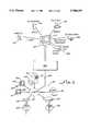
- FIG. 1is a block diagram of a digital video network apparatus connected to a network.
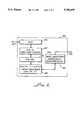
- FIG. 2is a block diagram showing additional details of the digital video network apparatus.
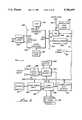
- FIG. 3illustrates in more detail one embodiment of the digital video network apparatus.
- FIG. 4illustrates an alternative embodiment of MPEG audio/video decompression circuits using an LSI L64112 for the video decoder, and an LSI L64111 for the audio decoder.
- FIG. 5depicts another alternative embodiment for MPEG audio/video decompression circuits.
- FIG. 6depicts further details of the audio decoder.
- FIGS. 7, 8 and 9are schematic diagrams depicting the structure of MPEG packet formats.
- FIG. 10The general structure of an MPEG encoder is shown in FIG. 10.
- FIG. 11is a flow chart showing steps in processing an MPEG data stream.
- FIG. 12is a flow chart showing steps in synchronizing with MPEG data.
- FIG. 13is a flow chart showing steps in processing MPEG data.
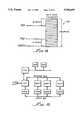
- FIG. 14shows an input data FIFO.
- FIG. 15is a block diagram depicting an MPEG encoder.
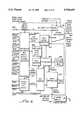
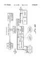
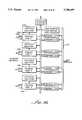
- FIG. 16depicts network protocol processing system interconnection circuits in detail.
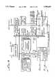
- FIG. 17is a diagram showing details of an ACI transmitter and receiver.
- FIG. 18Ais a schematic diagram depicting a conventional ISA bus design.
- FIG. 18Bis a schematic diagram depicting a PCI bus design.
- FIG. 19is a block diagram of an LSI ATMizer circuit which maybe used as an alternative embodiment of the network protocol processing unit.
- FIG. 20is a block diagram of a multi-port network connection.
- FIG. 21depicts an ATM packet structure.
- FIG. 22depicts certain ATM protocol sublayers.
- FIG. 23A, FIG. 23B, FIG. 23C and FIG. 23Dare diagrams illustrating sample VCR software structure for cell holding and channel support for segmentation.
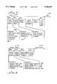
- FIG. 24is a flow chart showing processing steps executed by the network protocol processing unit.
- FIG. 25is a flow chart depicting steps executed by the network protocol processing unit in processing an ATM cell that has been received.
- FIG. 26is a flow chart depicting steps executed by the network protocol processing unit in processing an ATM cell that is to be transmitted.
- FIG. 27depicts a circuit for multiple connections to DS-1 terminations.
- FIG. 28depicts a block diagram of an Ethernet core interface.
- FIG. 29depicts a block diagram of a network switch which may be used in connection with the present invention.
- FIG. 30is a flow chart showing steps executed by the switch in processing a received packet.
- FIG. 31is a flow chart showing steps executed by a switch in processing the header of a received packet.
- FIG. 32is a flow chart depicting steps executed by the switch in retrieving and transmitting a packet.
- FIG. 33is a block diagram of an alternative embodiment of a network switch which may be used in connection with the present invention.
- FIG. 34is a block diagram of a Quad CASCADE circuit.
- FIG. 35is an alternative embodiment of a Quad CASCADE circuit including an external MAC interface.
- FIG. 36is a block diagram of a network architecture which may be used in connection with the present invention.
- FIG. 37is a block diagram of a switch and interface unit suitable for using the network architecture done in FIG. 36.
- FIG. 38is a block diagram of an Ethernet adapter.
- FIG. 39is an ATM adapter.
- FIG. 40is a block diagram of an alternative network architecture embodiment.
- FIG. 41is a block diagram of an alternative network architecture embodiment using a plurality of dedicated backbone buses.
- FIG. 42is a diagram illustrating a multi-protocol or uniprotocol single chip router.
- FIG. 43is a block diagram of an adapter for use in a PC system.
- FIG. 44is a block diagram of a network adapter.
- FIG. 45depicts a wireless network apparatus for use in connection with a transport device.
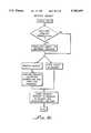
- FIG. 46is a flow chart illustrating steps in a hashing method in accordance with the present invention.
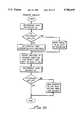
- FIG. 47is a flow chart further illustrating steps in a hashing method in accordance with the present invention.
- the present inventionmay be understood in connection with a description of a high speed digital video network apparatus 300, an example of which is illustrated in FIG. 1.
- the digital video network apparatus 300is shown connected in this example to a network 301.
- the digital video network apparatus 300is also shown connected in this example to a host computer 302.
- the computer 302has a video camera 303, which is a source of full motion video.
- the computer 302also has a digitizer 304, which is a source of digitized images.
- a microphone 305is connected to the computer 302, and is a source of digitized audio.
- the computer 302includes a CD-ROM drive 306, which can input multimedia program material including full motion video, digitized images, and digitized audio.
- the digital video network apparatus 300compresses data streams, such as the huge amount of data in digitized images and full motion video, into compact data streams that can be moved across the network 301, which would otherwise have a bandwidth that is too narrow to handle such huge amounts of data.
- the digital video network apparatus 300may be used to transfer data streams representing compressed video and audio over the network 301 to a remote computer 309. For example, full motion video from the camera 303 may be sent in a realtime fashion across the network 301 by the digital video network apparatus 300 to be displayed on a display screen 319 on the remote computer 309. Simultaneously, digital audio from the microphone 305 may be sent across the network 301 by the digital video network apparatus 300 to be heard on audio speakers 320 connected to the remote computer 309.
- the digital video network apparatus 300may receive data streams from the network 301 which comprise compressed video data, decode and decompress the data, and then output such received images and full motion video on a video display 307.
- the remote computer 309may send compressed video data over the network 301 to the digital video network apparatus 300, which can decode and decompress the data to produce images and full motion video to be displayed on the display screen 307 of the computer 302.
- data representing compressed digital audiomay be sent across the network 301 by the remote computer 309 to the digital video network apparatus 300 to be heard on the audio speakers 308 connected to the computer 302.
- a significant feature of the present inventionis the speed at which data may be exchanged over the network 301 and switched between a wiring hub 311 connecting computers 309, 317 to a remote node server 314 and a router 312 providing long distance LAN-to-LAN connections over telephone lines 313.
- the network 301 shown in FIG. 1includes a wiring hub 311 connecting computer 309, computer 317, and database server 310 to the network 301.
- a router 312is shown connected to the network.
- the router 312may provide long distance LAN-to-LAN connections over telephone lines 313.
- Leased telephone lines 313may provide a dedicated circuit at speeds ranging from 0.56 Mbits/sec to 1.544 Mbits/sec, and in some cases even 45 Mbits/sec.
- ISDN linesprovide connections at 128 Kbits/sec, but are not widely available.
- the illustrated network 301has a remote node server 314 connected to the network 301.
- the remote node server 314may be used to facilitate remote connections to the network 301 over telephone lines 315.
- a remote laptop computercould access the network 301 over the telephone lines 315 using a modem to connect to the remote node server 314.
- Remote node connectionstypically exchange packets of data in Novell IPX, Microsoft NetBEUI, or Internet IP format.
- the present inventionmay be advantageously employed in transferring data over the network 301 and transferring data across the network through the router 312 to and from a remote LAN connected over the telephone lines 313.
- the present inventionmay be advantageously employed where bandwidth limited telephone line links 313 are used, as well as a local network 301.
- the present inventionachieves speeds which allow for the realtime transfer of full motion video and simultaneous audio.
- the computer 302 and the remote computer 309may effectively function as video telephones, permitting users at the respective computers 302 and 309 to talk to each other and see live video images of each other in realtime. Uninterrupted voice and video can be provided between two networked computers 302 and 309.
- a user at computer 302could access video and/or audio data streams from a remote CD-ROM 321 on a database server 310 connected to the network 301.
- many efforts to allow remote access and control of computersinclude pcANYWHERETM, marketed by Symantec, CloseupTM, and Carbon CopyTM) have been less than satisfactory in some instances, especially when running WindowsTM or other graphical programs remotely. Graphical images may be transferred at speeds which allow WindowsTM and other graphical programs to be run remotely without serious performance degradation.
- a user at computer 317remotely accessing computer 302, could run a program on computer 302 and see a realtime display on the screen 322 of a mouse cursor movement similar to what he or she would see if running the same program on the computer 317.
- a fiber-optic cable, microwave link, satellite link, wireless radio frequency link, etc.could alternatively be substituted for the telephone lines 313 or 315.
- the inventionmay have particularly advantageous application in connection with the transfer of data streams over a wireless radio link, such as a cellular telephone link.
- the present inventionis also applicable to wireless networks.
- An interface for GSM, TDMA, FDMA, CDMA, or GSM1800could be added to permit wireless communication. Additional disclosure pertaining to an embodiment using a wireless link for the network 301 is contained in U.S. Pat. No. 5,340,978, the entire disclosure of which is incorporated herein by reference.
- the server 310has a UPS 318 supplying power to it.
- a printer 316is also shown. Images could be sent over the network 301 from the computer 302 to be printed on the printer 316.
- the network 301 shown in the illustrated example shown in FIG. 1is a packet switched network.
- the asynchronous transfer mode (ATM) protocol for the network 301is preferred.
- the ATM protocolprovides fast signaling with little delay, which is especially advantageous in video and voice transmissions.
- the networkcould use other protocols, such as Ethernet (with 10Base5, 10Base2, or 10BaseT connections), FDDI, token ring, CDDI, etc.
- Network protocol processing system interconnection circuits 323are shown in more detail in FIG. 16.
- the network protocol processing system interconnection circuits 323comprise a virtual channel memory (VCR) 501 for storing ATM cells for processing, segmentation and reassembly, a direct memory access (DMA) controller 502 for interconnecting to a PCI bus interface 504 and shared memory 341, an ATM cell interface (ACI) 505 for interconnecting to an ATM network 301, a pacing rate unit (PRU) 503 for automatically reducing the maximum transmission rate in response to a sensed congestion condition in the network 301, and an ATM processor unit (APU) 500 for controlling the DMA controller 502 and transfers between the VCR 501, the PCI bus 337 and the ATM network 301, and for performing segmentation and reassembly of conversion sublayer payload data units (CS-PDU's).
- the APU 500may also be used for performing conversion between the ATM protocol and the MPEG protocol.
- the network protocol processing unit 333is fabricated as a single integrated circuit chip on a single substrate as illustrated in FIG. 16, (along with the MPEG compression and decompression circuits).
- the function of the network protocol processing unit 333may be programmed by downloading software into an instruction RAM 506.
- the network protocol processing unit 333comprises a number of functional blocks which are illustrated in FIG. 16.
- the ATM Processing Unit (APU) 500is the "brain" of the network protocol processing unit 333. In this example, it is implemented as an on board 32-bit MIPS RISC based CPU 500 that may be used to control operation of the network protocol processing unit 333.
- the APU 500processes incoming cells and generates outgoing cells.
- the APU 500may translate incoming ATM packets to a different protocol, such as Ethernet, and generate outgoing packets in a different protocol.
- the APU 500may translate incoming packets in any protocol, such as Ethernet, to the ATM protocol and generate outgoing ATM cells or alternatively outgoing packets in any different protocol.
- the APU 500also provides operational control to support functions such as interleaved circuit termination (S&R) and cell switching of multiple ATM adaptation layer type cells, scatter-gather memory management operations, intelligent congestion control algorithms, traffic statistics gathering, and messaging between the network protocol processing unit 333 and a host CPU 338.
- S&Rinterleaved circuit termination
- cell switching of multiple ATM adaptation layer type cellsscatter-gather memory management operations
- intelligent congestion control algorithmstraffic statistics gathering
- messagingbetween the network protocol processing unit 333 and a host CPU 338.
- the APU 500runs software from the IRAM 506.
- the IRAM 506may be an on-board 1025 ⁇ 32 single cycle SRAM.
- the IRAM 506is preferably loaded at system reset, and the code preferably remains static in the IRAM 506 throughout system operation. However, if system failures occur, a diagnostic control routine may be downloaded to the IRAM 506 so that the APU 500 can assist in the troubleshooting process.
- a Virtual Circuit RAM (VCR) 501is a significant configurable aspect of the network protocol processing unit 333.
- the VCR 501may be implemented as a 1025 ⁇ 32 two Read/Write port SRAM 501.
- Software partitioning of the VCR 501may be used to vary tradeoffs in configuration such as the number of channels supported and the size, structure and speed of the RAM memory 334.
- Cells received from the ATM port sideare preferably written into the VCR 501 to await either reassembly or switching operations initiated by the APU 500.
- AAL 1, 2, 3/4 and 5 cellsmay be "built" in the VCR 501 by a combination of DMA operations and APU operations before being passed to the ATM transmitter 505.
- the VCR 501may also be used to store channel parameter entries, available buffer lists and other data structures which may be required for system operation. In some applications, all channel parameters entries will be stored in the VCR 501 while in other applications channel parameter entries may be stored in a main or shared memory 341 (combination systems are also possible).
- a Pacing Rate Unit (PRU) 503contains eight peak rate pacing counters (PRPC) that are used to control the rate of CS-PDU segmentation in an ATM protocol. Whenever one or more PRPCs times out, the PRU 503 asserts the APU's CpCond2 input allowing the APU 500 to poll for this time out condition. If the APU 500 finds CpCond2 set, it branches to a segmentation routine.
- PRPCpeak rate pacing counters
- the PRU 503also contains a channel group credit register (CGCR), which in this example is an eight bit, APU readable/writable register containing one bit for each PRPC.
- CGCRchannel group credit register
- a PRPC that has timed out but has not yet been serviced by the APU 500has its bit set in the CGCR.
- Software running on the APU 500can implement channel priority by selectively servicing channel groups that have timed-out.
- four of the eight 12-bit PRPCscan be configured into two general purpose 24-bit timer/counters for general purpose usage. These timer/counters provide certain features including APU interrupt on time-out capabilities.
- the PRU 503further includes a global rate pacing register (GRPR) which is further described below.
- GRPRglobal rate pacing register
- a DMA controller (DMAC) 502may be used by the APU 500 as a slave resource (as seen by the APU 500) to accomplish data transfers between the on-chip VCR 501 and memory mapped devices. While the APU 500 may be thought of as the "brains" behind DMA operations, the DMA controller 502 may be thought of as the "muscle” behind such operations. Because the APU 500 preferably initializes the DMA controller 502 at the beginning of each operation, the DMA controller 502 may effectively support an unlimited number of channels.
- the DMA controller 502is extremely powerful, supporting any combination of local and memory byte alignments on transfers. This powerful support of aligned and misaligned operations gives the network protocol processing unit 333 an ability to participate in scatter-gather operations.
- the DMA controller 502is also responsible for generating CRC32 results for AAL 5 SAR CS-PDUs.
- the DMA controller 502preferably operates in 32-bit address and 32-bit data transfer mode.
- An ATM Cell Interface (ACI) 505is the network protocol processing unit's 333 interface to the ATM port side circuitry, and includes an ACI Transmitter and a PCI Receiver.
- the illustrated ACI 505is 8 bits wide in both the transmit and receive directions and connects directly to the actual transmission convergence sublayer framing circuitry.
- the ACI 505In the receive direction, the ACI 505 is responsible for reconstructing ATM cells in the VCR 501 from data received from the framing logic 327.
- the ACI 505In the transmit direction, the ACI 505 is responsible for transferring cells from the VCR 501 to the framing logic 327.
- the ACI 505also contains data buffers and frequency decoupling logic to allow for a direct connection between the network protocol processing unit 333's ATM ports and the ATM line transceivers. In the illustrated embodiment, all metastability issues are addressed and solved by the network protocol processing unit 333.
- a secondary port 507is an eight bit port that can be accessed by the APU 500 directly through load and store commands.
- the secondary port 507may be used to pass information between the network protocol processing unit 333 and the RAM 334, or directly to the DMA controller 502 over a dedicated 32-bit bus.
- the secondary port 507may be used to transfer data directly from the RAM 334 to the PCI interface 504, and if desired, such data could be transferred to a host CPU 338.
- the secondary port 507can also be used to access the RAM 334 while the DMA controller 502 is busy and to read information from or store information in the RAM 334.
- the APU 500is a 32 bit RISC CPU based on the MIPS R3000 architecture. The inclusion of this powerful, user programmable CPU gives the network protocol processing unit 333 significant capabilities. Using software stored in the IRAM 506, the APU may be programmed to perform a range of functions such as cell building, including SAR header and trailer generation, ATM header retrieval from the channel parameter entry for the VC, ATM header manipulation and insertion, and DMA operation initialization for SAR SDU retrieval. The APU 500 may also be used for channel servicing sequencing.
- the APU 500may be used for generating SAR headers (AAL 1, 2 and 3/4) and trailers (AAL 2 and 3/4) during segmentation and reassembly (the CRC10 field is preferably generated and inserted by the ACI 505).
- SAR header generationmay include sequence number generation and checking as well as message type insertion and extraction (BOM, COM, EOM, SSM).
- the APU 500initiates appropriate DMA operations to accomplish SAR SDU retrieval from memory based real time data buffers (AAL 1) or CS-PDUs.
- AAL 1real time data buffers
- the APU 500is also responsible for ATM header retrieval and manipulation, including PTI and CLP field modification.
- PTI and CLP field modificationFor cells that are to be switched, the APU 500 makes the initial switching decision based on information contained in the channel parameter entry for the VC as well as for accomplishing VCI/VPI translation if such an operation is specified in the channel parameter entry.
- a network protocol processing unit 333 that may be used in an ATM networkis commercially available from LSI Logic Corporation of Milpitas, Calif. (hereinafter "LSI Logic") as the L64360 ATMizerTM.
- FIG. 19illustrates the ATMizerTM embodiment. Additional disclosure appears in the description contained in the manual entitled “L64360 and ATMizerTM Architecture Technical Manual” available from LSI Logic.
- the APU 500sets the main memory start address (byte offset), the local address and local byte offset, the number of bytes to be transferred and the transfer direction (read vs. write) in the DMA engine. Once these parameters have been written into the DMA engine, the DMA controller operates autonomously to accomplish the entire transfer.
- the APU 500initiates DMA operations to retrieve SAR SDUs during segmentation operations, to restore SAR SDUs to their respective CS-PDUs during reassembly operation, to switch entire cells, headers and trailers intact, to other memory mapped ATM ports during switching operations, to retrieve and restore channel parameter entries in applications utilizing additional memory to support an extended number of VCs or to retrieve a channel parameter entry to be appended to the end of a VCR based channel group in applications supporting on-chip caching of channel parameter entries in the VCR 501, and to transfer SAR SDUs to and from real time data stream buffers in applications supporting AAL1 circuit interfaces (such as T1 lines).
- AAL1 circuit interfacessuch as T1 lines
- the APU 500has write access to the eight peak rate pacing counters and their initialization registers (not shown).
- the APU 500sets the initial count values by writing a 12 bit value into one of the eight peak rate pacing registers.
- the APU 500can also read a channel group credit register to determine which PRPCs have expired.
- the pacing rate unit 503informs the APU 500 that a PRPC has timed-out by asserting the APU 500's CpCond2 input.
- the APU 500polls this condition by periodically executing a "Branch on CpCond2 True" instruction. If the APU 500 evaluates this condition as True it branches to a segmentation routine and begins segmenting the CS-PDUs specified in the individual channel parameter entries for the channel group whose PRPC 58a has timed-out (forcing the assertion of CpCond2).
- the APU 500will generate a number of cells per CS-PDU channel parameter entry, as indicated in the channel parameter entry, prior to proceeding to the next channel parameter entry in the channel group.
- the APU 500implements channel priority by being selective (and creative) in the order in which it handles segmentation when multiple PRPCs have timed out simultaneously and are awaiting service.
- the APU 500will check for received cells, and will interleave the generation of cells with the reception (termination or switching) of cells as well as with any other network protocol processing unit actions that may be required.
- the APU 500will queue cells for transmission by writing the VCR 501 start address of a cell into the cell address FIFO in the ACI transmitter. If no cell address is present in the FIFO when an end of cell boundary is reached, the transmitter will automatically send an IDLE cell.
- the APU 500will decide between cell switching and circuit termination on a per VC basis.
- the APU 500accomplishes internal cell switching by passing the VCR 501 addresses of a received cell targeted for internal switching to the cell address FIFO in the transmitter.
- a cell targeted for external switching(switching over DMA -- Data(31:0)) has its VCR 501 addresses passed to the DMA controller 502.
- the APU 500also is responsible for setting the global pacing rate register in order to shape the assigned cell content of the outgoing cell stream. For cells that are to be terminated (i.e. reassembled into CS-PDUs) the APU 500 retrieves the channel parameter entry for the VC over which the cell arrived to obtain information required to reassemble the SAR SDU into its corresponding CS-PDU.
- This informationincludes the memory address of the tail end of the CS-PDU under reconstruction.
- the APU 500then initiates a DMA operation to transfer the SAR SDU from the VCR 501 to memory by passing the DMAC the local (VCR 501) address of the SAR SDU, the memory address of the CS-PDU and the number of bytes of SAR SDU to be transferred.
- the DMA controller 502then executes the transfer, leaving the APU 500 free to do other things.
- the APU 500is responsible for memory buffer management. If memory is to be allocated to incoming CS-PDUs in "fragments", the APU 500 will track fragment boundaries, issue additional fragments to CS-PDUs as needed, and generate link lists of the fragments allocated to a given CS-PDU. The APU 500 may also generate messages directed to a host CPU 338 to inform the host of CS-PDU complete situations, error or congestion problems.
- the APU 500recognizes and deals with the difference between end-of-fragment boundaries and end-of-CS-PDU boundaries.
- the network protocol processing unit 333does not require a particular messaging system between the APU 500 and the host CPU 338.
- a messaging systemmay be implemented by polling an ATMizer -- Int input (connected directly to CpCond0 and tested with the "Branch on CpCond0 True" instruction) for an indication that the host wishes to communicate with the network protocol processing unit 333 and by setting the network protocol processing unit's Host -- Int output to indicate to the host that the network protocol processing unit 333 wishes to or has already passed a message to the host system.
- GP -- Int1 or GP -- Int2could also be used in addition to or in place of ATMizer -- Int as part of the messaging system.
- the APU 500can also read and/or write any DMA memory mapped or parallel port memory mapped location as part of a messaging mailbox system.
- a global pacing rate registerallows the APU 500 to set the percentage of IDLE cells to be sent over the ATM cell interface 505. This provides for aggregate traffic shaping and is a quick way of reducing data speeds upon congestion notification. The system may gradually return to full speed operation under the control of the APU 500.
- Congestion control algorithmsmay provide for immediate reaction to congestion notification. Fast response (within one cell time) results in fewer cells sent into a congested network, minimizing cell loss and CS-PDU retransmissions resulting in higher overall throughput. Congestion control routines are implemented through software stored in the IRAM 506 and can be modified to optimize them for any particular ATM network conditions.
- the network protocol processing unit 333is capable of executing or facilitating a wide variety of congestion control algorithms.
- the APU 500looks at the appropriate ATM header fields of each incoming cell for notification of congestion. If congestion notification is found to exist, the APU 500 can take immediate action. Such actions may include one or more of the following:
- the instruction RAM 506may contain 4096 bytes of user written software to power the APU 500.
- the IRAM 506 codemay be downloaded during system reset (Resetx asserted) through a series of memory write operations executed by the host processor 338 with the network protocol processing unit 333 serving as the target device.
- the network protocol processing unit 333may act as a slave device for the purpose of this download process.
- the CPU 338may accomplish such a data transfer to the network protocol processing unit 333 by issuing 1024 (or less) write operations to 1024 (or less) consecutive memory addresses. These memory address have common MSBs that result in external logic selecting the network protocol processing unit 333 as the targeted resource of the write operations.
- the network protocol processing unit 333responds to the assertion of DMA -- RdWrAck while Resetx is low by writing the data sourced by the host on DMA Data(31:0) into the on-board IRAM 506 on the rising edge of clock.
- the network protocol processing unit 333generates the IRAM 506 index (i.e. the IRAM 506 write address) internally, starting at location zero and incrementing the address by one word each time DMA -- RdWrAck is asserted.
- the IRAM 506 codeshould be written consecutively until the entire software has been written into the IRAM 506. Once the entire software has been written into the IRAM 506, the system can release the network protocol processing unit's 333 Resetx input and the APU 500 will begin software execution at the R3000 reset vector. DMA -- DataOEx and DMA -- AdrOEx should be deasserted during slave write operations.
- the network protocol processing unit 333will generate consecutive DMA memory addresses to IRAM 506 code downloading, beginning at memory address zero and incrementing by one word each time DMA -- RdWrAck is asserted. If the address sourcing capability of the DMA is used to boot from a ROM or some other device, DMA -- AdrOEx should be asserted during initialization. If programmed I/O is relied upon to configure the IRAM 506, DMA -- AdrOEx should most likely be deasserted to insure that the network protocol processing unit 333 does not drive the DMA -- Address (31:2) bus.
- the virtual channel RAM 501may be a 1024 word ⁇ 32 dual ported RAM that provides the network protocol processing unit 333 with significant capabilities. A number of network protocol processing unit 333 operations involve the transfer of data to and from the VCR 501.
- the VCR 501can be read and written by the DMA controller 502, the ATM cell interface 505 and the APU 500.
- Incoming cells from the ACI 505are preferably written into the VCR 501 prior to processing.
- the APU 500will decide how to process a cell. It can chose to terminate a cell (reassemble it into a CS-PDU or a data buffer) or to switch a cell (internally or externally).
- Outgoing cellsare preferably either constructed in the VCR 501 (segmentation) or transferred to the VCR 501 (external switching) prior to transmission.
- channel parameter entries, memory buffer lists, messages and other parameterscan all be stored within the VCR 501.
- the APU 500can swap out its channel parameter entry for the next in line.
- Channel parameter entries for channels that are active in the receive directionare stored in local memory 334. This allows a router to support an unlimited number of simultaneously active receive channels.
- the network protocol processing unit 333combines support for external channel parameter entries with a capability to do link list based CS-PDU scattering during reassembly (allocate memory in small "fragments" as needed). As a result, a router is able to support an unlimited number of open transmit and receive channels from a single unified DRAM based memory system with a single restriction on the number of transmit channels that can be actively undergoing segmentation at one time.
- the receiver in the ACI 505reconstructs cells received from the transmission convergence framing logic 327 in the VCR 501.
- the ACI 505allocates 64 bytes of VCR 501 memory to each incoming cell.
- the actual size of a cellis selectable (up to 64 bytes) and can be programmed in a system control register as part of the APU 500's system initialization routine.
- the receiverreconstructs cells beginning at VCR address 0000.
- the first 128 bytes (2 cells), 256 bytes (4 cells), 512 bytes (8 cells) or 1024 bytes (16 cells) of the VCR 501are set aside for received cell holders. Cells are written into the VCR 501 in a modulo 2, 4, 8 or modulo 16 fashion. Therefore, it is important that cells be processed before they are overwritten.
- Cell buffering in the VCR 501helps to decouple the incoming cell stream from memory interface latency and is especially helpful in situations where the APU 500 is temporarily unable to process incoming cells due to execution of an extended routine.
- All cellsshould be either moved to (external switching) or constructed in (segmentation) the VCR 501 prior to transmission.
- An area in the VCR 501can be set aside to act as the staging area for cell switching and generation.
- Outgoing cellsare transferred from the VCR 501 to the transmission convergence framing logic 327 by the transmitter in the ACI 505.
- the transmitterworks off of VCR 501 memory pointers.
- the APU 500Whenever the APU 500 wishes to have a VCR 501 resident cell transferred to the transmission convergence framing logic 327, it writes a VCR 501 pointer to the cell into the transmitter's cell address FIFO. The transmitter then handles the transfer automatically.
- a benefit to this pointer methodis that it enforces no restrictions on the internal location of cells slated for transmission except that they be VCR 501 resident. As a result, the network protocol processing unit 333 can switch received cell holder resident cells out over the transmitter by simply passing a pointer to the cell address FIFO (internal switching).
- the APU 500To switch a cell from an external device (i.e. to source a pre-existing memory based cell out over the transmitter of the ACI 505) the APU 500 first initiates a DMA operation to bring the cell into the VCR 501 from a temporary memory buffer. Then the APU 500 passes the VCR 501 pointer for the cell to the cell address FIFO in the same fashion as for internal switching.
- Segmentationrequires ATM and SAR (AAL 1, 2 and 3/4) headers and trailers (AAL 2 and 3/4) to be appended to the SAR SDUs by the APU 500.
- APU 500Once a cell is constructed in the VCR 501, the APU 500 again passes a pointer to the cell to the cell address FIFO and the transmitter sends the cell to the transmission convergence framing logic, one byte at a time.
- Such informationincludes:
- the ATM adaptation layer typethat is to be used to segment or reassemble cells originating or terminating on a given VC.
- a RAM based data structurethat contains all of the pertinent information about a single VC is referred to as a channel parameter entry for the VC.
- the network protocol processing unit 333does not enforce any channel parameter entry data structure.
- the channel parameter entry data structureis software programmable, as well as how VCs are grouped together and how the segmentation process will be conducted on a grouping.
- the APU 500 softwareshould be written to work with the channel parameter entry data structure architecture of a given system. For example, a system that supports AAL5 CS-PDU segmentation and reassembly will require less information in a channel parameter entry than a system that supports AAL5 CS-PDU segmentation and reassembly and cell switching. Furthermore, a system that supports simultaneous segmentation and reassembly of AAL 1, 2, 3/4 and 5 CS-PDUs will require a more detailed channel parameter entry for each VC.
- the ACI 505is coupled through a multiplexer 508 to the VCR 501.
- An internal access bus 509is used to pass data between the APU 500, the PRU 503, con DMA controller 502, the VCR 501, the ACI 505, and a prefetch buffer 510.
- a second bus 511is used to pass data and instructions from the APU 500 to the DMA controller 502 or the secondary port 507.
- the APU 500can access information in the RAM 334 through the secondary port 507 in the same cycle that data from the ACI 505 is being transferred to the DMA controller 502.
- a DMA-VCR bus 512is used to transfer data between the VCR 501 and the DMA controller 502.
- a data bus 513is used to transfer data between the DMA controller 502 and the PCI interface 504.
- a separate address and byte enable bus 514is preferably provided between the DMA controller 502 and the PCI interface 504.
- a data bus 515is provided for transfers in one direction
- a data bus 516is provided for transfers in the other directions
- an address bus 517is provided for addressing the RAM 334.
- a separate address busmaybe provided between the secondary port 507 and the RAM 334 to speed access to the RAM 334.
- a serial interface 518is also shown in FIG. 16, which can be used for downloading software into the IRAM 506, or for transferring serial data through the DMA controller 504 or the secondary port 507.
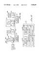
- FIG. 17illustrates additional details of the ACI 505.
- the ACI transmitter 519 and the ACI receiver 520are shown in FIG. 17. Both are coupled to the VCR 501.
- the VCR 501may be partitioned into a transmit cell builder areas 521, received cell holders 522, and current receive cell pointer areas 523. The operation of these elements is further described in "L64360 and ATMizerTM Architecture Technical Manual" mentioned above.
- An assigned cell address FIFO 524 shown in FIG. 17is used for temporary storage of cell addresses.
- the bus 337is preferably a PCI bus.
- An illustration of PCI bus designis shown in FIG. 18B.
- a PCI bustypically provides a 32 bit 33 MHz data path.
- An alternative bus designis shown in FIG. 18A. This depicts an ISA bus.
- An ISA expansion busprovides an 8 bit 8 MHz data path.
- a PCI busis preferred.
- Framing logic 525, 526is provided for each port.
- a transceiver 527is provided for the first port, and is interfaced to a host bus 529. Data may be transferred to and from a host shared memory 530.
- a transceiver 528performs a similar function for the second network port. It should be understood that a plurality of network ports may be utilized.
- FIG. 21 and FIG. 22illustrate formatting for ATM cells.
- FIG. 23Ashows a map for ATM cells stored in the VCR 501.
- FIG. 23Bshows an example of an AAL5 receive cell holder and transmit cell builder.
- FIG. 23Cdepicts an AAL5 transmit channel parameter entry table.
- FIG. 23Ddepicts an AAL5 receive channel parameter entry.
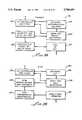
- FIG. 24is a flow chart depicting processing by the network protocol processing unit of ATM cells.
- FIG. 25depicts in more detail the processing of a received ATM cell.
- FIG. 26depicts a flowchart showing in more detail the processing of an ATM cell for transmission.
- the present inventioncontemplates multiport connections to various networks 301 which may employ different protocols. For example one network may use an ATM protocol, while another network may use an Ethernet protocol.
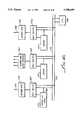
- FIG. 27depicts an interface useful for multiple DS one terminations in an embodiment also having an ATM port and an interface to a network employing Ethernet protocol.
- FIG. 28illustrates an embodiment of a suitable Ethernet core.
- a networkin this example using Ethernet 10 base-2 or 10 base-5, may be connected to a media attachment unit 537.
- the media attachment unit 537is coupled to an attachment unit interface 536.
- the attachment unit interface 536is coupled to a squelch unit 535.
- a twisted pair network connectionmay be achieved using a link integrity and receive circuit 539 which is coupled to the squelch unit 535.
- a pre-distort shaping and link integrity generation circuit 538may also be used.
- a phase locked loop and data recovery unit 534is connected to the squelch unit 535.
- a Manchester encoder 533is coupled to the pre-distort shaping and link integrity generation circuits 538, and to the attachment unit interface 536.
- the phase lock loop and data recovery unit 534is coupled to a media access control (MAC) circuit 532.
- the Manchester encoder 533is also coupled to the MAC unit 532.
- the MAC unit 532includes a receive engine 541 and a transmit engine 540. These are coupled to a host interface unit 531.
- a multiport network adapteris provided.
- a multiport switch on a chipprovides significant advantages in miniaturization, increased performance, transparent and rapid protocol to protocol conversion, and eliminates the need for any external address resolution logic.
- the multiport network switching circuitry shown in FIG. 29is provided on a single chip or semiconductor substrate.
- Network lines 555are connected to a first network port 542.
- the first network port 542is coupled to a bus 553.
- the bus 553is preferably a high speed bus, such as a PCI bus.
- the operation of the first network port 542is controlled by control logic 545.
- Hashing logic 546is used for filtering address and header information.
- Information used by the control logic 545 in switching packets among various portsis stored in a static RAM 547.
- a second port 543is shown in FIG. 29, and is connected to second network. As shown in FIG. 29, a plurality of ports may be provided, and port 544 is intended to indicate that.
- a packet buffer RAM 550is coupled to the bus 553.
- a memory 549is used for storing pointers and DMA information.
- a DRAM control interface 551is provided, which controls a DRAM memory 552.
- the control logic 545which may be a CPU, checks the ports 542, 543 and 544. Depending upon the protocol employed internally, the data received over a particular port 543 may require translation from one protocol to another. The control logic 545 first checks to determine whether the port 543 in which data is being received is one which requires translation. If so, the control logic 545 translates the received packet to the backbone protocol employed internally. For example, an ATM protocol may be employed as the backbone protocol.
- the multiport switchthen processes the header of the packet in parallel with storing the packet in memory. Details concerning the procedure for processing the header are shown in FIG. 31.
- the control logic 545processes the packet header information.
- the hashing logic 546searches for the correct port that a received packet should be switched to when it is transmitted. Addresses of systems and associative ports are stored in the static RAM 547, and used by the hashing logic 546 to identify the correct switching information for a received packet. In parallel with these steps, the received packet data is transferred from the port 543 to the packet buffer RAM 550.
- the control logic 545stores memory pointers in memory pointer memory 549 which indicates where the packet is stored in the packet buffer RAM 550. Alternatively, packets may be stored in DRAM 552, and the pointer memory 549 would contain a pointer indicating that the information was stored in DRAM 552.
- the DRAM control interface 551would use the pointer information to retrieve the actual data from DRAM 552 when the control logic 545 requests retrieval of a particular packet.
- the packet data information and the packet headerare both stored in the DRAM 552.
- the speed of the DRAM 552is important. In some embodiments, the performance of the bus 553 will be limited by the speed of the DRAM 552.
- a CPU interface 548is provided.
- a direct memory access controllercould be provided coupled to an external bus. This could provide a means for cascading multiple switches together. Network statistics are maintained and stored in the network statistics circuit 554.
- the control logic 545processes the packet header to first determine who the intended recipient of the packet is.
- the control logic 545checks the list of known recipients maintained in the static RAM 547 to determine if the intended recipient is on the list. If the recipient is not on the list, the packet must be marked to be sent by broadcasting it over all of the remaining ports 543 and 544. Such a packet will be sent by a technique sometimes referred to as flooding.
- the control logic 545uses the hashing logic 546 determines the port 543 which is associated with that recipient.
- the control logic 545stores a pointer to the memory location in the DRAM 552 for the packet information and the port 543 that the packet is to be transmitted on, and this information is stored in the pointer memory 549.
- the control logic 545attempts to update or build its lists maintained in the static RAM 547.
- the control logic 545will then examine the packet header to determine who the sender is.
- the control logic 545using the hashing logic 546, will determine whether the sender is on the list maintained in the static RAM 547. If the sender is not on the list, the control logic will add the sender to the list and record the port 542 that the sender is connected to.
- the control logic 545will check the memory pointer list 549 for indications of packets. It will determine whether there is a packet to be sent. If there is, it will check the port 544 to determine if the port is clear. If the port is not clear, the control logic 545 will check to determine whether the memory is filling up. If available memory for additional packets is still available, control logic will proceed to check for another packet to be sent. However, if the memory is filling up, and in danger of becoming full, the control logic 545 will need to take action to insure that it does not run out of memory. In that event, the control logic 545 will execute a priority interrupt.
- interrupt routinewould be to jam the port 544.
- jamming the port 544will cause collisions with packets being transported over the port 544. Those collisions will be detected by users connected to the network, and the network protocol will require such users to wait a random period of time before attempting to retransmit the packets. During this waiting period, the control logic 545 can seize the network and transmit the desired packet over the port 544 before memory fills up.
- control logic 545When a packet is to be retrieved and transmitted, control logic 545 will free the system bus 553. The control logic 545 will then look up the memory pointer in memory 549, and use the information in the memory pointer to retrieve the packet from memory 552. The control logic 545 will then route the packet to the port 544 indicated by the information stored in the memory 549. The packet will then be transmitted over the port 544 to the network connected to that port.
- Hashing logic 546may implement suitable hashing algorithms, which are used in network switching systems such as routers 312 and hubs 311 to quickly search a table of address/port combinations to determine the correct port for a specific destination address. This enables the packet to be switched to the port containing the end user to whom the packet is addressed, eliminating the need to broadcast the message across all ports in a shotgun approach. Flooding the network with broadcast packets increases traffic on the network, and slows throughput. Hashing logic 546 is used to implement fast methods for determining the correct port for a given destination address, and by avoiding the need to broadcast packets, such arrangements effectively increase the bandwidth of the network 301.
- the address of the end useris contained in 48 bits in the header of the packet.
- the hashing logic 546implements a suitable hashing algorithm which in a preferred embodiment can be performed on a variable number of bits from one to all 48.
- a variable windowcan be applied to the address so that, for instance, bits three through seven may be chosen as the bits to hash.
- the hashdoes not always have to start with bit zero.
- a hash key sizecan be selected by software programming.
- a "window" locationi.e., the bits selected from the 48 bits of address information which will be hashed, can be selected under software control using a microprocessor implementation.
- FIG. 46depicts a flow chart of certain steps performed during hashing.
- a keyis selected from a subset of the total address bits contained in the packet header in step 800.
- Hash logic 546computes an address in a table in step 801.
- the computed address contentsare compared to the entire destination address to identify whether there is a match.
- the corresponding port address stored in the tablehas been located and the search is successful. If the contents do not match, a collision has occurred, and the hash address is incremented by one in step 805, and the comparison is performed again as described above in step 803.
- the systemlearns the end user address and corresponding port from the originator of a packet.
- the systemrecords the port address from the incoming message, hashes the address within the packet corresponding to the originator in step 807, looks up in the table for that particular hash address value in step 808, and compares the contents in step 811. If there is a match, the system does nothing since the end user address and port location are already stored in the table and therefore known by the system. This is shown by the step "end" in FIG. 47 associated with step 811. If the hash address is empty the system writes to that location the end user address and the port number in step 809. If the address is full but the contents are different, the system increments the hash address by one value in step 812, and proceeds to step 811 to compare the contents of that location as described above. Collisions are thus handled by allowing for overflow in the memory.
- Extra table memorycan be used to record the number of messages sent to a particular address from the hashing exercise performed on every packet. In that way, the most popular address locations could be saved in the table and the less popular addresses dropped so that the overflow memory locations for each hash address can be minimized.
- the memory size, the number of ports, the hashing algorithm, the size of the overflow list for collisions, the key size and the key window on the addressare all programmable.
- h(K)K modulo M
- his the hash function address result
- Kis the key
- Mis a value such that 0 ⁇ h(K) ⁇ M. Since the scheme described above enables variable key sizes and key windows, the user may select the appropriate values for the key "K” and the value "M". The user may therefore wish to hash on three bits of the end user address corresponding to bits five, six and seven (note variable window). Since three bits in a digital system correspond to eight specific values, and since h(K) ⁇ M, M must be greater than eight. Since the best values for M to minimize collisions are odd, not multiples of three, and are a prime number, the number 11 works well. The corresponding h(K) can then be multiplied by the size of the memory table to compute the address.
- the ports 542, 543, and 544may employ circuits disclosed in "L64380 Quad CASCADE Technical Manual” (Dec. 2, 1994) available from LSI Logic. Considerable circuits are shown in more detail in FIG. 34 and FIG. 35.
- FIG. 35shows an external MAC interface 557.
- FIG. 33shows an alternative embodiment of the multiport switch shown in FIG. 29, including a DMA controller 558.
- FIG. 36depicts a network architecture incorporating switches 563 which may be constructed in accordance with FIG. 29, or alternatively, the circuit illustrated in FIG. 33.
- Each switch 563may be connected to network interfacing circuitry 562, 565, 564, or 566.
- one of the network switches 563is coupled to a Quad CASCADE circuit 562.
- the Quad CASCADE circuit 562provides connection to four network ports.
- One of the network connectionshas been identified by reference numeral 555.
- Lines 568are connected to a different network.
- lines 569are connected to yet another network.
- the details concerning a suitable Quad CASCADE circuit 562are shown in "L64380 Quad CASCADE Technical Manual" (Dec. 2, 1994), available from LSI Logic.
- FIG. 36illustrates an interconnection 566 to a 100 Mbs Ethernet network.
- a suitable compacted and scalable dedicated Ethernet corealso referred to as a CASCADE core, are disclosed in "Compacted and Scalable Dedicated Ethernet (CASCADETM) Core Technical Manual" available from LSI Logic.
- the network architecture illustrated in FIG. 36utilizes a uniform backbone protocol on an internal bus 559.
- a CPU or controller 560may be used to control arbitration and switching of packets among the various switch circuits 563. Packets may be stored in memory 561. An optional memory 567 may be provided address storage. Preferably, a CPU or control logic 545 is provided in each switch 563. Packets can be converted to the backbone protocol by the switch 563 before they are placed on the bus 559. Alternatively, the controller 560 (which may also be a CPU) may handle conversion of packets to the backbone protocol.
- This network architectureprovides for transparent communication among networks having different protocols.
- the network architecture shown in FIG. 36can simultaneously switch graphic between a plurality of different networks employing different protocols, such as Ethernet, ATM, FDDI, Token Ring, etc.
- the networkscan be LANs, WANs, or a mixture of both.
- the controller 560may strip off packet headers and store addresses of the port that the received is to be switched to.
- the controller 560in one embodiment may employ the procedures shown in FIG. 30, FIG. 31, and FIG. 32 for processing and switching packets.
- pointers and packet datamay both be stored in the same memory 561, which may be partitioned as desired.
- an embodiment of the network architecturemay provide that the backbone controller 560 need not process packet headers to determine the port to which the packet should be switched. If the architecture of FIG. 29 is used for each switch 563, each switch 563 may form its own hashing algorithm to determine the address and port for each packet that is to be transferred over the bus 559. In such a system, a switch 563 would notify the controller 560 of the port that a packet is to be switched to. The controller 560 may check the destination switch 563 associated with that port to determine if the port is busy. If not, the controller 560 may then free the backbone bus 559 to permit transfer of the packet from the sending switch 563 to the destination switch 563.
- the sending switch 563may store the packet temporarily in backbone memory 561 and notify the controller 560 of the destination port to which the packet is to be switched. When the port is available, the controller 560 may notify destination switch 563. The destination switch 563 may then retrieve the packet from backbone memory 561 and transmit it out over the destination port.
- FIG. 37illustrates an alternative embodiment for a switching interface unit 575.
- connectionis made to a 10 Mbs Ethernet through network connection 555 and connections made to a 100 Mbs Ethernet through network connection 568.
- the network connection 568is facilitated by a 100 Mbs Ethernet MAC and encoder/decoder circuits 566.
- the network connection 555is made through a 10 Mbs Ethernet MAC and encoder/decoder 573. Circuits such as those shown in FIG. 28 may be employed.
- SRAM memory 572is provided for packet buffering.
- the buffer 572is coupled to switching control logic 571.
- the switching control logic 571is coupled to the backbone bus 559. Referring to FIG.
- the controller 560may perform hashing of packets to determine the port to which they should be switched utilizing switching interface units 575 such as that shown in FIG. 37.
- the Ethernet MAC 566may be replaced with SONET/SDH framers and ATMTC circuits 327, and ATMSAR circuits 328, such as those shown in FIG. 2.
- SONET/SDH physical layer interfaceis disclosed in "SONET/SDH Physical Layer Interface (PLI) Technical User's Manual" (April 1994) available from LSI Logic. Additional disclosure is shown in "51/155 Mbps SONET ATM UNI Processor" data sheet (1994) available from LSI Logic.
- interface architecturesuch as is shown in FIG. 38 and FIG. 39 may be employed. These interfaces are described in more detail later.
- each switch 563 and network interface 564should be fabricated on a single chip or substrate.
- switch 563 and Quad CASCADE circuit 562should be fabricated on a single chip or substrate.
- FIG. 40illustrates an alternative embodiment of a network architecture.
- the network architecture illustrated in FIG. 40utilizes a CPU 560.
- the switches 563are each connected to a first backbone bus 559.
- Each ASIC switch 563is also connected to a second backbone bus 576.
- the additional backbone bus 576may be used to increase performance of the network architecture.
- Datamay be exchanged between two switches 563 simultaneously while data is being exchanged between two other switches 563, or between the CPU 560 and DRAM 577.
- each ASIC switchmay have its own associated DRAM 577. Packets may be temporarily stored in DRAM 577 until the switch 563 is ready to process the packet, or while the switch 563 is processing a packet header.
- the CPU 560may be a RISC processor, an i960 controller, a MIPS controller, or an x86 CPU such as a 286, 386, or 486, or it may be a Pentium processor.
- the interface 573could be a MAC Singleton, or could be a Quad CASCADE circuit 562.
- packets to be switched between the switches 563may be stored in a central DRAM 561.
- the address informationis stored in a memory 567 connected to each switch 563.
- each DRAM 577may have a direct connection 585 to a backbone bus 576. Both the address information and the packet are forwarded to the DRAM 577 associated with each switch 563.
- Each switch 563determines the port address that contains the end user that a received packet is intended for. Thus, a switch 563 will signal to the host bus 576 or 559 controlled by the microprocessor 560 that it wants to forward the packet to the switch 563 containing the address port. The microprocessor 560 will check to see if the end port is busy and, if not, allow packet to be forwarded from the DRAM 577 to the switch 563 that controls the port connected to the end user that the packet is intended for.
- the microprocessor 560may maintain a table of pending packet transfers and, when the port is free, access the DRAM 577 directly to transfer the packet to the destination switch 563 when the port is available. Alternatively, the microprocessor 560 may transfer packets from one DRAM 577 to another, and simply notify the associated switch 563 each time that a packet is placed in the DRAM 577 associated with that switch 563.
- FIG. 41illustrates an alternative embodiment of a network architecture. This embodiment has particular advantages in speed and throughput by employing multiple dedicated backbone buses.
- Each ASIC switch 563may comprise the circuit configuration shown in FIG. 29. Alternatively, the structure depicted in FIG. 33 may be used.
- Each switch 563incorporates its own hashing logic 546 and maintains its own list or table of recipient addresses and associated ports in a memory 547.
- Control logic 545determines the port associated with a recipient address, and determines which switch 563 is the destination switch.
- a first switch 563determines that the recipient of a packet to be switched is connected to a network 582 that is connected through a port associated with a second switch 563'.
- the control logic 545will route the packet to a dedicated backbone bus 580 which connects only the first switch 563 and the second switch 563'.
- Another examplemay involve a packet received over an ATM network connected to ATM interface 590.
- the fourth switch 563'"will in this example, convert the ATM packet to the backbone protocol.
- the recipient of the packetis connected to a network 583.
- the third switch 563"is connected to the network 583 through a 10 Mbs Ethernet Quad CASCADE interface 562.
- the fourth switch 563'"transfers the packet to the third switch 563" over a dedicated backbone bus 581.
- the third switch 563"may then transmit the packet to the intended recipient over the port associated with the network connection 583. It should be appreciated that packets may be switched between the third switch 563" and the fourth switch 563'" over dedicated backbone bus 581 simultaneously while packets are being transferred from the first switch 563 to the second switch 563' over the dedicated backbone bus 580.
- a bus 559connects the first switch 563 with the fourth switch 563'.
- a second backbone bus 576connects the second switch 563' with a third switch 563".
- a third backbone bus 579connects the first switch 563 with the third switch 563.
- a fourth backbone bus 580connects the first switch 563 with the second switch 563'.
- a fifth backbone bus 581connects the third switch 563" with the fourth switch 563'".
- a fifth backbone bus 584connects the second switch 563' with the fourth switch 563'".
- each switch 563has a dedicated backbone bus connecting it to each of the remaining switches.
- Each switch 563may maintain a table indicating the protocol employed by the networks connected to the other switches. In the network architecture illustrated in FIG. 41, a uniform backbone protocol need not be utilized. If the first switch 563 is switching a packet over bus 580 to the second switch 563, and both are connected to only networks employing the identical protocol, the packet can be switched unmodified. Modification of packets need occur only when switching between two switches connected to networks employing different protocols. For example, if the first switch 563 is switching a packet from over the first backbone bus 559 to the fourth switch 563'" shown in FIG. 41, the packet must be converted between protocols because the fourth switch 563'" is connected to an ATM network.
- the packetmay be switched to the fourth switch 563'" and converted by the fourth switch 563'" before it is transmitted over the ATM network.
- a particular protocolmay be employed over each backbone bus 559, 576, 579, 580, 581, and 584 which is optimized for transfer between the two particular switches 563 that are connected by each respective bus.
- a single clear channelis provided between each switch 563 to improve performance. It should be appreciated that a packet received over network connection 583 which is intended for a recipient connected to the network associated with network connection 586 may be processed without accessing any backbone bus 579, 576 or 581.
- the third switch 563"may switch the packet directly between network 583 and network 586 without accessing a backbone bus.
- FIG. 44illustrates a network adapter incorporating a direct memory access controller function.
- the advantage of the illustrated adapteris that the direct memory access controller function relieves the host system CPU from having to do data transfers across the system bus. This improves system efficiency because the host system CPU can use the time that would otherwise be involved in supervising data transfers to perform other tasks.
- the adapter 650includes a network interface unit 651 coupled to a RAM 652.
- a direct memory access controller 653accesses information stored in the RAM 652.
- the direct memory access controller 653is coupled to a PCI interface 654 which provides an interface to the PCI system bus 657 of the host CPU.
- the direct memory access controller 653may directly supervise and control transfers of data from the RAM 652 to the host memory 656 of the host CPU over the PCI system bus, thus freeing the host CPU to perform other tasks.
- the adapter 650is controlled by a high speed RISC CPU 655.
- FIG. 42is a diagram illustrating a multiprotocol or uniprotocol single chip router. This configuration has been described in one or more of the patent applications cross-referenced and incorporated herein by reference. A description will not be repeated.
- the architecture illustrated in FIG. 42may be improved by incorporating an expanded system on a single chip which combines integration of the framing technology, transmission convergence functions, and external back end bus.
- a single chipcarries and does all of the ATM traffic for adapter cards or switches. This single chip is coupled to the PCI bus of a host computer, and connects the host computer to an ATM network, and performs all functions necessary to transfer data between the PCI bus and the direct connections to the network.
- the single chipcould provide connection to a network employing Ethernet protocol FDDI, CDDI, Token Ring, etc.
- FDDIEthernet protocol
- CDDICDDI
- Token Ringetc.
- a version of this adapteris shown as PCI to Ethernet adapter 605 in FIG. 43.
- An alternative version PCI to ATM adapter 606is also shown.
- the adapter 606may be configured as the ATM adapter circuit 590 shown in FIG. 39.
- a SONET/SDM framer unit 591is connected directly to the ATM network.
- the SONET/SDM framer unit 591is coupled to an ATM transmission convergence unit 592.
- the ATM transmission convergence unit 592is coupled to an ATM segmentation and assembly unit 593.
- the ATM segmentation and assembly unit 593is coupled to memory 594 for cell buffering.
- the memory 594is coupled to a PCI controller 595 which preferably includes FIFOs.
- the PCI controller 595is coupled to a PCI bus.
- An optional microprocessor 596may be included.
- a suitable PCI to Ethernet adapter 605may be configured in FIG. 38.
- An AUI or MII unit 597is connected directly to the Ethernet network.
- the AUI 597is coupled to a Manchester encoder/decoder unit 598 which may alternatively be a 4b/5b encoder/decoder.
- the Manchester unit 598is coupled to an Ethernet MAC 599.
- the MAC 599is coupled to a memory 600 for packet buffering.
- the memory 600may be similar to the buffer 594.
- the memory 600is coupled to a PCI controller 601, which may be similar to the PCI controller 595.
- An optional microprocessor 602may be provided.
- circuits shown in FIG. 38are all manufactured on a single chip or substrate.
- circuits shown in FIG. 39are all manufactured on a single chip or substrate.
- the single chippreferably includes PMD functions including transceiver and clock recovery.
- the microprocessor 602 and 596may be used to handle conversion from network format to a format that is directly useable by the host CPU.
- the on board microprocessor 602 and 596frees up the host CPU to perform other functions.
- multiple portsmay be combined on a single chip providing connections to different network protocols (ATM, Ethernet, FDDI, Token Ring, etc.) to provide multiple external communication port connections transparent to the host CPU.
- ATMATM, Ethernet, FDDI, Token Ring, etc.
- a digital video network apparatus 300includes, in combination, network protocol processing system interconnection circuits 323 and compression/decompression encoder/decoder circuits 324.
- the network protocol processing system interconnection 323comprises packet conversion logic or a suitable microprocessor 325 for conversion between a network protocol, such as asynchronous transfer mode (ATM) packets, and the data protocol used to handle large data streams, such as MPEG packets.
- ATMasynchronous transfer mode
- MPEGMPEG
- the illustrated examplewill be described herein in connection with the preferred ATM network protocol and the MPEG format. However, it should be understood that the invention is not necessarily limited to the particular protocols and standards used in the illustrated embodiment.
- the network protocol processing system interconnection 323 shown in FIG. 2further comprises a PMD circuit or unit 326, an ATM TC and SONET/SDH framing circuit or unit 327, and an ATM SAR circuit or unit 328.
- the illustrated compression/decompression encoder/decoder circuits 324preferably comprise MPEG audio and video compression and decompression circuits 329.
- the PMD unit 326functions as a line transceiver and performs clock recovery functions.
- the TC/Framer unit 327handles error checking, framing, line coding, serial-to-parallel conversion, etc. Examples of different framer types which may be employed include T1, T3, E1, E3, STS3, STS12, STM, and STM4.
- the SAR 328handles ATM segmentation and reassembly.
- the conversion logic or microprocessor 325handles conversion between ATM packets and the MPEG format.
- the conversion unit 325comprises a microprocessor, packet conversion to alternative formats such as Ethernet may only involve a software change.
- the PMD unit 326may be replaced by appropriate interface circuits for CDPD, PCS, TDMA, CDMA, or GSM. Such interface circuits may include a microcontroller, DSP circuits, DAC/ADC, error correction, equalization circuits, etc.
- the SONET/SDH Framing unit 327would be optional.
- modem circuitsshould be added between the PMD unit 326 and the Framing circuits 327. Suitable modem circuits include QAM, QPSK, VSB, and forward error correction such as Reed Solomon or Viterbi. In a CATV application, the PMD unit 326 would be optional. If the ATM format is not used in a CATV application, then the TC/Framer circuits 327 and the SAR circuits would be optional. The SONET/SDH format would be optional.
- the input/output lines 330may be connected to the network 301.
- the input/output lines 331may be connected to the computer 302; however, the digital video network apparatus 300 is preferably integrated into the computer 302. This may be better understood in connection with FIG. 3.
- FIG. 3illustrates in more detail one embodiment of the digital video network apparatus 300.
- the digital video network apparatus 300is connected to the network 301 through a physical layer interface circuit 332.
- the physical layer unit 332is coupled to a network protocol processing unit 333.
- the network protocol processing unit 333includes an ATM cell interface (ACI) for connecting to the physical layer 332.
- the network protocol processing unit 333also includes a DMA port, a secondary port, and a serial interface.
- the secondary portis connected to a RAM 334 through a 32-bit bus 335.
- the network protocol processing unit 333is connected to a serial PROM 336 through the serial interface.
- the DMA port of the network protocol processing unit 333is connected to a 32-bit data bus 337.
- a CPU 338is also coupled to the data bus 337.
- the data bus 337is preferably a PCI bus providing a 32-bit 33 Mhz data path.
- the CPU 338has an associated instruction RAM (IRAM) coupled to the CPU 338 through an instruction bus 340.
- IRAMinstruction RAM
- the CPU 338executes a program stored in instruction RAM 339.
- the CPU 338also accesses a shared memory 341. In this example, the shared memory 341 is used to store data.
- the PCI bus 337may also be referred to as the host bus 337.
- the CPU 338 and shared memory 341are both coupled to a second data bus 342.
- mass storagesuch as a hard disk drive 343 is coupled to the second data bus 342.
- the disk drive 343could be coupled to the PCI bus 337.
- the second data bus 342could be a PCI expansion bus.
- the digital video network apparatus 300may be implemented with a single data bus, i.e., the host data bus 337 and the second data bus 342 could be combined as a single bus.
- utilizing a second data bus 342allows MPEG encoding and decoding operations to be performed independently of the operations of the network protocol processing unit 333.
- the network protocol processing unit 333During transmission and reception of packets from the network 301, the network protocol processing unit 333 will from time to time use the PCI bus 337 in order to access the shared memory 341.
- the network protocol processing unit 333has its own processor (referred to as an "APU") which offloads certain operations from the host CPU 338. For example, processing associated with segmentation, reassembly, etc. of ATM cells is performed by the APU on the network protocol processing unit 333, which frees the CPU 338 to control the MPEG encoding and decoding operations, and to perform other functions such as error handling routines.
- the MPEG compression/decompression encoder/decoder circuits 329compress the hugh amount of data normally present in digitized images and motion video into compact data streams that can be moved across the network 301, even though the network 301 may have a bandwidth which would otherwise be too narrow to handle such hugh amounts of data.
- the MPEG compression/decompression circuits 329may be considered as a "black box" that receives coded video data over the bus 342 and produces a decoded video data stream at output 350 for subsequent display on the display screen 307.
- the block diagram in FIG. 3shows how an MPEG video decoder 344 may be used in a video decoding system 300.
- MPEG coded data placed on the second data bus 342may be passed to a demodulator/ECC/decryption circuit 351, if necessary. If the video has been encrypted (for example, as part of a copy protection scheme), the decryption circuit 351 will descramble the data. In the illustrated example, a decryption circuit 351 normally will not be required.
- MPEG coded datais then coupled to a video decoder 344, either from the circuit 351 if it is necessary, or the data may come directly from the second bus 342.
- the video decoder 344is connected to a video coder and digital-to-analog converter 347.
- the digital-to-analog converter 347drives a display 307.
- the video coder 347may be used to modulate the video in either a NTSC or a PAL standard format for display on a conventional television set 307.
- the video decoder 344is coupled to a RAM 346 which is used to store frames of video during decoding operations.
- the video decoder 344preferably supports direct connection to commercial DRAMs 346 for use as frame stores 346.
- the video decoder 344uses frame stores 346 for intermediate frame reconstruction and display. In this example, no external components are required to interface between the video decoder 344 and the DRAMs 346.
- the video decoder 344 pinoutallows the connection to DRAM 346 to be made on a PCB single layer.
- the video decoder 344exclusively controls the DRAM frame stores 346. However, in a preferred embodiment, it is possible to access the DRAMs 346 through a user port 352 on the video decoder 344 for test, verification, and access of data used during the vertical blanking interval of the display 307.
- the video decoder 344provides a digitized video output 350 for subsequent display on the display 307.
- This datais in a CCIR601 color format having a "Y,” “Cb,” and “Cr” component.
- the digitized video output 350operates with a luminance sample rate that is usually exactly half of the rate of the system clock 361. This is nominally 13.5 MHz from a 27-MHz clock.
- the video decoder 344also provides video synchronization signals for the display 307.
- the user port 352allows a user to program system options and to monitor operation of the decoder 344. Errors flagged by the video decoder 344 and certain user data may be read through the user port 352. However, the video decoder 344 will not maintain unread user data indefinitely.
- a preferred embodimenthas a user data FIFO that is 32 bytes deep and is accessible through a register.
- the registermay be LSI Logic L64000 MPEG-2 Video Decoder which is described in the "L64000 MPEG-2 Video Decoder Technical Manual” (July 1994) and in the manual entitled “L64000B MPEG2 Video Decoder w/ PP Filters” (Jun. 23, 1994). Additional disclosure concerning suitable registers is contained in the "L64112 Digital TV MPEG Decoder Technical Manual” (November 1993). All three of these manuals are available from LSI Logic.
- the CPU 338must read data transmitted in the user data records of the MPEG bitstream, even if that data is subsequently used to control some aspect of the video display subsystem 329. The CPU 338 should read this data, then write it to internal state registers in the video decoder 344, if necessary.
- the illustrated example of the video decoder 344operates satisfactorily to produce an NTSC standard display at image sizes of 720 ⁇ 480 pixels, with a frame rate of 30 fps (720 ⁇ 576 at 25 fps for PAL).
- the coded data channel 342may have a sustained bit rate up to 15 Mbit/sec.
- the video decoder 344supports lower resolution images than 720 ⁇ 480 in dimension multiples of 16 pixels. As the resolution decreases, the amount and bandwidth of DRAM memory 346 required for frame stores 346 also decreases. However, a preferred video decoder 344 continues to use the same memory bus 342 width of 32 bits across its full resolution range.
- the audio decoder 345can accept either serial or parallel digital MPEG audio data.
- the audio decoder 345includes an internal DRAM controller, which interfaces with an external DRAM 348 to provide memory for a channel buffer 348.
- the audio decoderproduces an output 355 which is coupled to a CD audio digital-to-analog converter 349.
- the digital-to-analog converter 349produces a stereo audio output which is fed to speakers 308.
- Suitable decompression decoder circuitsare commercially available from LSI Logic Corporation of Milpitas, Calif.
- the L64112 Digital TV MPEG Decodermay be used for the video decoder 344.
- the L64112is specifically designed for use in digital video decoding systems based on the MPEG1 algorithm. Additional disclosure relating to the L64112 is contained in the "L64112 Digital TV MPEG Decoder Technical Manual” (November 1993) mentioned above.
- Another LSI product called the L64000is designed for use in systems that must be MPEG2 compliant. Disclosure relating to the L64000 is contained in the "L64000 MPEG-2 Video Decoder Technical Manual” (July 1994) mentioned above. Additional disclosure relating to the L64000 is contained in the manual entitled “L64000B MPEG2 Video Decoder w/ PP Filters” (Jun. 23, 1994) mentioned above.
- the L64000is pin-compatible with the L64112.
- L64111 MPEG Audio DecoderAn LSI product called the L64111 MPEG Audio Decoder may be used for the audio decoder 345. Additional disclosure relating to the L64111 is contained in the "L64111 MPEG Audio Decoder Technical Manual” (September 1993) available from LSI Logic.
- L64002 MPEG-2 Audio/Video Decoder Technical Manual(Nov. 18, 1994), which is available from LSI Logic, contains disclosure materials describing the LSI L64002 MPEG-2 audio/video decoder, which has both a video decoder 344 and an integrated audio decoder 345.
- the audio decoder 345uses the same memory 346 as the video decoder 344 for its channel buffers, thus eliminating the need for separate DRAM 348.
- the L64002also integrates an on-screen display controller capable of overlaying an image up to 720 ⁇ 480 pixels (720 ⁇ 576 for PAL) at up to 4 bits/pixel on top of an MPEG video sequence while it is being decoded. Bitmaps for on-screen display may be assembled off-screen then made visible instantaneously. Hardware panning and scrolling of overlay data is supported.
- FIG. 4illustrates an alternative embodiment of MPEG audio/video decompression circuits 329 which specifically uses an LSI L64112 for the video decoder 344, and an LSI L64111 for the audio decoder 345.
- an inexpensive eight-bit microcontroller 353 and associated ROM or EEPROM 354are utilized.
- the EEPROM 354may also be a flash EPROM, or a PROM.
- the L64112 MPEG video decoder 344is designed to provide a single-chip solution for a digital TV set top.
- the L64112 MPEG video decoder 344accepts serial or parallel coded channel data directly from a demodulator sub-system 351 or from an eight-bit microcontroller 353 at a sustained data rate of up to 15 Mbit/sec. It extracts the MPEG video data stream from the MPEG system stream and performs error detection before fully decompressing the video data.
- the L64112 MPEG video decoder 344outputs digitized video data 350 in an interlaced or progressive format together with horizontal and vertical sync signals. This digital YUV output interfaces directly to most off-the-shelf NTSC/PAL encoders 347.
- the L64112 MPEG video decoder 344has complete on-chip channel buffer and display buffer control, and it supports direct connection to commodity DRAMs 346 for frame reconstruction.
- the only external devices required with the L64112 MPEG video decoder 344are an inexpensive eight-bit microcontroller 353 for testing, initialization, and monitoring the status of the video decoder 344, and commodity DRAMs 346 for storing channel and display data. This simplifies the system design, testing, and manufacturing process.
- the external system controller (microcontroller) 353is responsible for test, initialization, and real time control of the L64112 MPEG video decoder 344.
- the interface between the system controller 353 and the L64112 video decoder 344is eight bits wide and fully asynchronous.
- the system controller 353defines the operational mode of the L64112 video decoder 344.
- the L64112 video decoder 344 operational modesare controlled through a number of internal state registers, which may be read or written over the interface. These internal state registers are described more fully in the "L64112 Digital TV MPEG Decoder Technical Manual" (November 1993) mentioned above.
- Device initialization parametersinclude frame size, sync pulse widths, active image size and position, frame mode, horizontal re-sizing, and channel buffer size. The programmability of these parameters increases the flexibility of the L64112 video decoder 344 for systems with different resolutions and display system characteristics.
- the behavior of the L64112 video decoder 344can be monitored by the system controller 353. Parameters include channel buffer 346 fullness, detected bitstream errors, and status of video sync signals. Access to the frame stores 346 is arbitrated in the L64112 video decoder 344. Frame store 346 accesses from the system controller 353 have a lower priority than any other access in the system.
- the L64112 video decoder 344has multiple interrupt sources, which include detectable errors, channel status, and display status. Interrupts are signalled to the system controller 353 over a single interrupt pin, and are selectively maskable by the controller 353. Pending interrupts may be read from an internal register. Interrupts make the program stored in the EEPROM 354 which is being executed by the system controller 353 more efficient because there is no need to poll the interface.
- Frame memories 346can be tested by randomly reading and writing them through the interface.
- An internal address indirection registercontrols the addressing of these accesses.
- the L64112 video decoder 344arbitrates between these accesses and other subsystems within the L64112 video decoder 344.
- Channel datacan be written directly through the system controller interface instead of through the serial channel interface.
- Direct writingsupports parallel interfaces found in computer systems, particularly CD-ROM players.
- An internal control bitselects the input channel source. It is the user's responsibility to ensure that writes to the parallel channel interface do not exceed the channel rate.
- a state bitis provided that allows the user to poll the busy status of the channel.
- An output pinis also provided that reflects this status. This pin is used where a hardware handshake is needed.
- Coded bitstream datais typically written serially into the L64112 video decoder 344. On each rising edge of a serial channel clock, a single bit and an associated data-valid signal are read. The peak sustained rate on the serial interface is a function of the device clock. At the nominal frequency of 27 MHz, this rate is 15 Mbit/sec. The instantaneous burst rate on the serial channel is a function of device characterization. A supply/demand characteristic defines the burst/non-burst rate behavior. The burst rate limits the packet length and packet separation in a variable channel rate system.
- Synchronization circuitry in the channel interfaceallows the device clock and the channel clock to run at different rates.
- the L64112operates on MPEG 1 bitstream syntax.
- the usermay select the highest level of the MPEG grammar which the L64112 decoder will see on the channel.
- the highest level the device is capable of completely decodingis the video sequence layer. If presented with a system layer bitstream, the L64112 video decoder 344 parses out and decodes the packet layer.
- MPEG-1is as defined in IS 11172.
- User data in the channelis buffered on-chip on the L64112 video decoder 344 and may be read by the system controller 353.
- the on-chip user data FIFOis intended to buffer data until the system controller 353 can service an interrupt and read the data. If the data is not read, the FIFO overflows and all user data in the FIFO is invalidated until the user data FIFO is reset. It is the responsibility as ape system controller to act on user data as appropriate.
- the system controller 353must inform the bitstream parser to stop decoding and search for a new intra-frame resynchronization point.
- the L64112 video decoder 344then freezes on the last complete anchor frame until a new sequence is acquired. Program acquisition time is a function of the encoder sequence header length. B frames with a broken link are decoded unless the system controller 353 forces resynchronization.
- the system controller 353restarts the L64112 video decoder 344 when the channel buffer reaches an adequate threshold. Suitable circuits for audio and video synchronization of an MPEG-2 Encoded bit stream is disclosed in the manual entitled “MPEG A/V AppNote" (Oct. 17, 1994) available from LSI Logic.
- a seamless switch between virtual program channelsmay be achieved if the different channels within a channel group have a temporally aligned group of frame headers.
- Virtual channel switchis a function of the channel demultiplexer in the decoder 344.
- the L64112 video decoder 344handles virtual channel switching like a regular P-frame to I-frame transition in the bitstream. Note that in a virtual channel scheme there cannot be any B-frames carrying over across the group of frames boundary because these would constitute a broken link in the new group, leading to a discontinuity in the video or depletion of the channel buffer.
- Constraining B-frames in a virtual channel schemeis a function of the encoder.
- the system controller 353can force the display to freeze if the channel becomes depleted due to a channel switch.
- the channel bufferhas no explicit panic modes because it is generally not known where buffer thresholds should be set. If the channel buffer underflows, the user controller 353 may be optionally interrupted and the L64112 video decoder 344 instigates a freeze frame. If the channel buffer overflows, an interrupt is generated.
- the typical recovery mechanismis identical to a channel switch; that is, the decoder freezes after the last good frame, the broken frame is discarded, and the decoder is set to resynchronize on a new group of frames. In a system with a properly matched encoder and decoder 344, panic modes should never be needed.
- FIG. 5depicts another alternative embodiment for MPEG audio/video decompression circuits 329.
- the embodiment shown in FIG. 5uses a source of MPEG data such as a cable interface, CVD, hard disk, or CD-ROM player 306.
- An interface chip 356is provided.
- the bus 342may be implemented as an 8-bit or 16-bit bus.
- FIG. 6depicts further details of the audio decoder 345. While the audio decoder 345 uses an external channel buffer 348 for temporary storage of audio frames that have been removed from the stream, an internal DRAM controller 357 in the example described herein uses a 256K ⁇ 4 fast page mode DRAM 348.
- the channel buffer 348can handle at least one second of data, which facilitates audio-video synchronization or other delay compensation.
- Synchronization of audio and video streamsrequires that an external system controller 353 monitor the video and audio presentation time stamps.
- the audio decoder 345delays audio frames (stores them in the buffer 348) until the controller 353 determines that the correct presentation time has been reached. At this point the controller 353 commands the audio decoder 345 to start decoding from data in the channel buffer 348. Using the channel buffer 348, the audio decoder 345 can compensate for at least one second of delay between audio and video data.
- the audio decoderprovides a 16-bit PCM output 355 by means of a multiplexed serial output bus 355 compatible with commodity PCM serial D-to-A converters (DACs) 349.
- a bypass commandallows four-wire PCM serial audio data to be passed directly from serial input to serial output 355 with only a multiplexer delay.
- the audio decoder 345provides the ability to conceal errors in data. When this function is enabled, two choices of response to error are provided: (1) repeat the last error-free audio frame, or (2) muting.
- a multipass synchronization methodminimizes frame synchronization errors. With this technique, successive valid syncs must be acquired before synchronization is established.
- the audio decoder 345When initialized, the audio decoder 345 synchronizes itself by monitoring the data stream and locating an audio frame in the data stream. When MPEG data is input, the audio decoder 345 strips away all unneeded information, retaining only the audio and control data. The audio and control data is then partially expanded and stored in the channel buffer 348. When the appropriate control signals are seen, this stored data is played; that is, decompression is performed and the data is output in PCM format.
- the datais first synchronized in step 400 to the system clock (SYSCLK) 361, then sent to an input data FIFO 362 (shown in more detail in FIG. 14).
- the synchronization step at the system levelis shown in more detail in FIG. 12.
- the decoders 344 and 345are required to parse MPEG packet layers in order to extract a presentation time stamp from the bitstream.
- the presentation time stampis the essential parameter for audio and video synchronization.
- MPEGdoes not guarantee that the packet data field of the packet layer is emulation-free.
- the decoders 344 and 345must therefore predict the occurrence of start codes 385 in the system bitstream 373 based on the length field of the previously occurring header 381. (See step 408).
- the system level synchronization circuitrymay be considered a filter that only passes the packet data field 374 of the packet layer.
- the usermay select which of several elemental video streams the decoders 344 or 345 present as valid packets.
- the video decoder 344uses an internal four-bit register for this purpose. This register is described more fully in the "L64112 Digital TV MPEG Decoder Technical Manual" (November 1993) mentioned above. (The system synchronization circuitry may be bypassed only in systems using elemental video streams.)
- the video decoder 344does not assume any data alignment for the incoming data stream. The alignment is imposed on the stream by the detection of synchronization symbols in step 410 and 413 of FIG. 12. Packet stuffing data is not written to the channel buffers 346 or 348.
- Errors occurring in the packet headermay cause synchronization failure. It is possible that the decoders 344 and 345 will initially synchronize incorrectly in step 410 to a bitstream due to emulation of resync codes 385 in the data field. However, the probability of this incorrect synchronization occurring is very low. Mis-synchronization failures can only occur if the decoders 344 and 345 are already not synchronized. If such a failure is encountered, the decoders 344 and 345 will subsequently reacquire synchronization within two packet times.
- the video decoder 344parses the elemental video data stream in order to decode the MPEG video.
- a flow chart for parsingis shown in FIG. 13.
- the video decoder 344operates on the video sequence layer and below.
- the video decoder 344synchronizes to the bitstream independently of the alignment or error condition of the data from the system synchronizer. The only constraint is that the data should be MPEG video data.
- the post-parseroperates on data in steps 419 through 424 as it is read out of the channel buffer.
- the post-parseris capable of operating on one MPEG symbol every cycle.
- bitstream errorsThere are two types of bitstream errors flagged by the video decoder 344--decode errors, and channel errors. If decode errors occur in the bitstream, the post-parser or on-chip microcontroller detects them by checking for correct grammar. The parser or microcontroller generates a maskable interrupt if a decode error is found. Depending on the context of the error, the decoder 344 may perform error concealment to prevent the erroneous data from reaching the picture store. Channel errors occur due to the overflow or underflow of the channel buffer 346. The video decoder 344 generates a maskable interrupt during normal operation if the channel buffer 346 becomes full or empty. In a properly designed system, the channel buffer 346 should never become full, and should only become empty if the decoder 344 loses synchronization.
- the usermay read the status of the three bitstream error flags at any time.
- a mask wordcan be set, indicating which of the error flags may generate an interrupt.
- the video decoder 344synchronizes on the first sequence start code which it finds in the bitstream. Assuming no errors, the video decoder 344 will periodically resynchronize on subsequent sequence start codes. Errors either found in the bitstream syntax or signalled from the channel during the processing of the video sequence layer header are not maskable, and are flagged as decode errors. This includes errors detected during the processing of user data. Error recovery is accomplished by waiting for a new sequence start code.
- the video decoder 344only enters the group of pictures layer from the video sequence layer if the device is synchronized to the video sequence layer and no errors have been detected.
- Spurious group start codes occurring when the video sequence layer is not synchronizeddo not cause the decoding of data within the group of picture layer.
- Errors found in the bitstream syntax, or signalled from the channel during the processing of the group of pictures layer headerare not maskable, and are flagged as decode errors. Error recovery requires waiting for a new group start code or sequence start code. If an extension start code is found in the group of pictures layer, the extension record is decoded until the next legal start code, and written to the auxiliary FIFO.
- the video decoder 344only enters the picture layer from the group of pictures layer if no errors have been detected in the group of pictures header. Errors in the header of the picture layer will have different propagation effects depending on the picture coding type. However, because an error in this header would typically be the transmutation of one picture type to another or to code an incorrect temporal reference, all errors in the picture layer header are flagged as decode errors. Error recovery requires waiting for a new picture layer, group of pictures layer, or video sequence layer. If the extra information bit is set, the syntax is decoded and written to the auxiliary FIFO. No error is flagged. If an extension start code is found in the picture layer, the extension record is decoded until the next legal start code, and written to the auxiliary FIFO. No error is flagged.
- the post-parserresynchronizes to any resync symbol in the channel buffer, regardless of its alignment. If the post-parser is not synchronized, it reads symbols at the maximum rate until it either regains synchronization or the channel buffer empties. If the post-parser receives a media error code or flag, it attempts to conceal errors up to the next resync symbol.
- the post-parseruses the resync symbols in the channel buffer 346 to keep track of the current grammar layer of the bitstream.
- the post-parserattempts to conceal errors either flagged as media errors in the bitstream or found to be errors during decoding at the slice layer and below layers.
- the post-parserdetects the following errors:
- the input data FIFO 362buffers the data and supplies it to a pre-parser 363.
- Various flagsshown in FIG. 14, signal the extent to which the input data buffer 362 is full or empty. The flags are made available for flow control.
- the input data FIFO 362is not part of the channel buffer 348, and its flags do not reflect the state of the channel buffer 348.
- the pre-parser 363performs stream parsing in step 401 of FIG. 11. This is also depicted in step 414 of FIG. 13.
- the pre-parser 363detects the pack start code 385 or system header start code and uses one of these to synchronize to the ISO stream in step 414 of FIG. 13.
- the pre-parser 363looks for packet header information and attempts packet identification.
- the preparser 363identifies audio frame information in step 416 and discards all else.
- the pre-parser 363calculates the CRC and separates the header information from the audio data and sends the audio data to the channel buffer 348 in step 418.
- a decoder 364receives data from the channel buffer 348 and fully decodes the data using an appropriate MPEG algorithm. The reconstructed data is then sent into a PCM serial converter 365.
- the DRAM controller 357handles the read/write and refresh activities of the external channel buffer DRAM 348.
- the channel buffer 348stores blocks of partially decoded audio data prior to reconstruction of the data in the decoder 364.
- a play director 366maintains a list of the frames in the channel buffer 348.
- the play director 366also holds certain header information required to complete the decoding operation of each frame.
- the framesare normally accessed as a circular buffer. It is possible to skip or replay frames (cue and review) while they are in the play director 366.
- the play director 366is also used in error concealment.
- the 16-bit reconstructed stereo pair 355is output in a PCM format compatible with most serial D-to-A converters 349. Various modes are supported.
- An output multiplexer 367controls routing of serial data signals. It can be program-controlled or hardwired to select one of the following three outputs: (1) the serial output (SERO) is set to zero; (2) input data is unprocessed and passed through unchanged; or (3) the output is the PCM format output of the decoder 364. In the bypass mode, the audio decoder 345 passes all four PCM inputs 360 unaltered to the output 355. All signals retain their temporal alignment.
- SESOserial output
- the audio decoder 345also includes an ancillary data FIFO 368 coupled to the controller interface 359.
- a vector RAM 358is coupled to the decoder 364.
- the decoder 364can operate with bit rates up to 384 Kbits/sec. stereo or dual channel with sampling frequencies of 32 KHz, 44.1 KHz, or 48 KHz. Once the decoder 364 has started decoding, it takes data from the channel buffer 348.
- the decoder 364uses a two-pass system. In the first pass, the decoder 364 parses the bitstream, separating out the sync, header information, allocations, and scalefactors, performs the CRC check, and removes ancillary data. In the second pass, the decoder 364 provides degrouping, inverse quantization, scaling, and subband synthesis. By performing two passes, the decoder 364 can mask errors by repeating the same frame, and the two-pass approach allows identifying false audio syncs.
- Rate controlis the ability of the decoder 364 to deliver a continuous PCM output 355 correctly timed while the input 360 is coming in bursts.
- the rate control mechanismhas two parts. The first part is the input data FIFO 362. Part of the input data FIFO 362 compensates for the variations in processing time for different parts of the pre-parser 363. The rest of the input data FIFO 362 allows data burst rates up to 7.5 Mbytes/second (60 Mbits/sec.) for a length of 128 bytes, until the pre-parser 363 processes this data at its 15 Mbit/sec rate. These rates are valid for a system clock rate (SYSCLK) 361 of 30 MHz.
- SYSCLKsystem clock rate
- the second channel rate controlis the channel buffer 348.
- This buffer 348is filled at a 15 Mbit/sec. rate and is emptied at the PCM output sample rate.
- MPEGis a standard for the representation of compressed audio and video signals. It allows for data interchange between compatible systems and standardized decoding methodologies.
- ISO CD 11172defines formats for digital data streams for both video and audio.
- the ISO system stream formatis designed to accommodate both audio packets and video packets within the same framework for transmission.
- an MPEG encoder 329Given an elementary stream of data (for audio data, this is called an audio stream), an MPEG encoder 329 first digitally compresses and codes the data.
- the MPEG algorithmoffers a choice of levels of complexity and performance for this process.
- FIG. 15A suitable MPEG encoder is shown in FIG. 15. Additional details and description are contained in a document entitled “Introduction to the VISC Architecture,” which is available from LSI Logic.
- Each audio frame 370contains audio data 374, error-correction data 375, and optional user-defined ancillary data 376.
- the error correction data 375referred to as the audio frame cyclic redundancy code (CRC) 375, contains a 16-bit checksum, which can be used to detect errors in the audio frame header 389.
- the audio frames 370are then sent in packets 371 grouped within packs 372 in an ISO MPEG system stream 373.
- the packs 372 in system streams 373may contain a mix of audio packets 371 and video packets 378 for one or more channels. Packs 372 may contain packets 371 from separate elementary streams. MPEG can support multiple channels of program material, and a decoder 344 & 345 given access to a system stream 373 may access large numbers of channels.
- Encoding a video signalis perhaps more complicated than encoding an audio signal.
- a video signalIn order for a video signal to be compressed, it must be sampled, digitized, and represented by luminance and color difference signals (Y, Cr, and Cb).
- the MPEG standardstipulates that the luminance component (Y) be sampled with respect to the color difference signals (Cr and Cb) by a ratio of 2:1. That is, for every two samples of Y, there is to be one sub-sample each of Cr and Cb, because the human eye is much more sensitive to luminance (brightness) components than to color components.
- Video samplingtakes place in both the vertical and horizontal directions. Once video is sampled, it is reformatted, if necessary, into a non-interlaced signal.
- An interlaced signalis one that contains only part of the picture content (every other horizontal line, for example) for each complete display scan.
- an encodermay process it further to select an appropriate display window within the total image area and to convert it to a different resolution.
- the encodermust also choose which picture type to use.
- a picturecorresponds to a single frame of motion video, or to a movie frame. There are three picture types:
- Intra-coded picturesare coded without reference to any other pictures
- P-picturesare coded using motion-compensated prediction from the past I- or P-reference pictures.
- Bidirectionally predictive-coded picturesare coded using motion compensation from a previous and a future I- or P-picture.
- a typical coding schemecontains a mixture of I-, P-, and B-pictures.
- I-picturemay occur every half a second, to give reasonably fast random access, with two B-pictures inserted between each pair of I- or P-pictures.
- a macroblockconsists of a 16-pixel by 16-line section of luminance component and two spatially corresponding 8-pixel by 8-line sections, one for each chrominance component. Motion vectors give the displacement from the stored previous picture.
- Motion within the picturesmeans that the pixels in the previous picture will be in a different position from the pixels in the current block, and the displacement is given by motion vectors encoded in the MPEG bitstream.
- Motion vectorsdefine the motion of a macroblock, which is the motion of a 16 ⁇ 16 block of luminance pixels and the associated chrominance components.
- B-picturesWhen an encoder provides B-pictures, it must reorder the picture sequence so that the video decoder 344 operates properly. Because B-pictures use motion compensation based on previously sent I- or P-pictures, they can only be decoded after the referenced pictures have been sent.
- a macroblockis a 16 ⁇ 16 region of video, corresponding to 16 pixels in the horizontal direction and 16 display lines in the vertical direction.
- every luminance component of every pixel in the horizontal directionis captured, and every luminance component of every line in the vertical direction is captured.
- every other Cb and Cr chrominance componentis similarly captured.
- the resultis a 16 ⁇ 16 block of luminance components and two 8 ⁇ 8 blocks each of Cr and Cb components.
- Each macroblockthen consists of a total of six 8 ⁇ 8 blocks (four 8 ⁇ 8 luminance blocks, one 8 ⁇ 8 Cr block, and one 8 ⁇ 8 Cb block).
- the spatial picture area covered by the four 8 ⁇ 8 blocks of luminanceis the same area covered by the each of the 8 ⁇ 8 chrominance blocks. Since there are half as many chrominance samples needed to cover the same area, they fit into an 8 ⁇ 8 block instead of a 16 ⁇ 16 block.
- the encoderFor a given macroblock, the encoder must choose a coding mode. The coding mode depends on the picture type, the effectiveness of motion compensation in the particular region of the picture, and the nature of the signal within the block.
- the encoderAfter the coding method is selected, the encoder performs a motion-compensated prediction of the block contents based on past and/or future reference pictures. The encoder then produces an error signal by subtracting the prediction from the actual data in the current macroblock.
- the error signalis separated into 8 ⁇ 8 blocks (four luminance blocks and two chrominance blocks) and a discrete cosine transform ("DCT") is performed on each 8 ⁇ 8 block.
- the DCT operationconverts an 8 ⁇ 8 block of pixel values to an 8 ⁇ 8 matrix of horizontal and vertical spatial frequency coefficients.
- An 8 ⁇ 8 block of pixel valuescan be reconstructed by performing the inverse discrete cosine transform on the spatial frequency coefficients. In general, most of the energy is concentrated in the low frequency coefficients, which are located in the upper left
- Compressionis achieved by a quantization step, where the quantization intervals are identified by an index. Since the 5 encoder identifies the interval and not the exact value within the interval, the pixel values of the block reconstructed by the IDCT have reduced accuracy.
- the DCT coefficient in location 0, 0 (upper left) of the blockrepresents the zero horizontal and zero vertical frequencies and is known as the DC coefficient.
- the DC coefficientis proportional to the average pixel value of the 8 ⁇ 8 block. Additional compression is provided through predictive coding, since the difference in the average value of neighboring 8 ⁇ 8 blocks tends to be relatively small.
- the other coefficientsrepresent one or more non-zero horizontal or non-zero vertical spatial frequencies, and are called AC coefficients.
- the quantization level of the coefficients corresponding to the higher spatial frequenciesfavors the creation of an AC coefficient of zero by choosing a quantization step size such that the human visual system is unlikely to perceive the loss of the particular spatial frequency unless the coefficient value lies above the particular quantization level.
- the statistical encoding of the expected runs of consecutive zero-valued coefficients of higher-order coefficientsaccounts for considerable compression gain.
- the coefficient sequenceis specified to be a zigzag ordering. Zigzag ordering concentrates the highest spatial frequencies at the end of the series.
- the encoderperforms run-length coding on the AC coefficients. This process reduces each 8 ⁇ 8 block of DCT coefficients to a number of events represented by a non-zero coefficient and the number of preceding zero coefficients. Because the high-frequency coefficients are more likely to be zero, run-length coding results in good video compression.
- VLCvariable-length coding
- the final compressed video datais now ready to be transmitted to a storage device 343 for later retrieval and decompression by a video decoder 344 or over a transmission medium for reception and decompression by a remotely located decoder 344.
- the MPEG standardspecifies the syntax for a compressed bitstream.
- the video syntaxcontains six layers, each of which either supports a signal processing or system function.
- the layers and their functionsare:
- Sequence Layer--Random Access UnitContext
- the MPEG syntax layerscorrespond to a hierarchical structure.
- a sequenceis the top layer of the video coding hierarchy and consists of a header and some number of groups-of-pictures (GOPs).
- the sequence headerinitializes the state of the decoder, which allows the decoder to decode any sequence without being affected by past decoding history.
- a GOPis a random access point, that is, it is the smallest coding unit that can be independently decoded within a sequence, and consists of a header and some number of pictures.
- the GOP headercontains time and editing information.
- Picturesconsist of a header and one or more slices.
- the picture headercontains time, picture type, and coding information.
- a sliceprovides some immunity to data corruption. Should the bitstream becomes unreadable within a picture, the decoder should be able to recover by waiting for the next slice, without having to drop an entire picture.
- Slicesconsist of a header and one or more macroblocks.
- the slice headercontains position and quantizer scale information. This is sufficient for recovery from local corruption.
- Blocksare the basic coding unit, and the DCT is applied at this block level. Each block contains 64 component pixels (picture elements) arranged in an 8 ⁇ 8 order. Pixel values are not individually coded, but are components of the coded block.
- a macroblockis the basic unit for motion compensation and quantizer scale changes. Each macroblock consists of a header and six component 8 ⁇ 8 blocks: four blocks of luminance, one block of Cb chrominance, and one block of Cr chrominance.
- the macroblock headercontains quantizer scale and motion compensation information.
- a macroblockcontains a 16-pixel by 16-line section of luminance component and the spatially corresponding 8-pixel by 8-line section of each chrominance component.
- a skipped macroblockis one for which no DCT information is encoded.
- the picture area covered by the four blocks of luminanceis the same as the area covered by each of the chrominance blocks, due to subsampling the chrominance information to model sensitivity of the human visual system.
- Each luminance pixelcorresponds to one picture pixel, but because the chrominance information is subsampled with a 2:1 ratio both horizontally and vertically, each chrominance pixel corresponds to four picture pixels.
- MPEG audio encodingis intended to efficiently represent a digitized audio stream 373 by removing redundant information from digitized audio input 395.
- the digitized audio input 395is first passed through a frequency filter bank 393.
- MPEGuses different encoding techniques. These techniques, called “layers,” provide different trade-offs between compression and signal quality.
- the MPEG encoder 390uses two processes for removing redundant audio information: (1) a coding and quantization unit 392; and, (2) a psychoacoustic modelling unit 391. Coding and quantization are techniques that are applied to data 374 that has been mapped into the frequency domain and filtered into subbands by the frequency filter bank 393.
- the psychoacoustic modeling unit 391determines the best allocation of data within the available data channel bandwidth based on human perception.
- the resultant compressed datais then assembled by a bitstream formatter 394 into the MPEG format.
- MPEG audio decodinginvolves: (1) identifying and removing a channel's audio frames 370 from the audio packets 371 in the system stream 373; (2) managing the temporary storage of frames 370; (3) applying appropriate algorithms for decoding the audio frames 370; (4) merging decoded audio frames 370 back into continuous audio; and, (5) limiting the effect of transmission errors.
- the audio decoder 345produces decoded audio data 374 in an industry-standard Pulse Code Modulation (PCM) serial format, allowing the use of commodity parts, i.e., PCM D-to-A converters 349 for audio output.
- PCMPulse Code Modulation
- An ISO system stream 373contains this compressed data in a specified sequential format.
- the highest level MPEG system syntaxis the ISO system stream 373.
- the system stream 373is composed of a sequence of packs 372, as shown in FIGS. 7 and 9.
- An MPEG pack 372is composed of a pack layer header 380 & 381, a system header packet 382 & 383, a sequence of packets 372 & 378, and ends with an ISO 11172 end code 384.
- the pack layer header 380 & 381contains a 32-bit pack start code 385 used for synchronization purposes, and a system clock reference or value 386.
- the system header packet 382 & 383contains a variety of housekeeping data and in particular contains a system stream ID 387 used to differentiate multiple system streams.
- a sequence of one or more packets 371, 377, 378, 379contains either encoded audio or encoded video stream data.
- the ISO 11172 end code 384is the final element in an MPEG pack 372.
- An MPEG audio packet 371contains an audio packet header 388 and one or more audio frames 370.
- An audio packet header 388contains the a packet start code which identifies it as an audio packet 371.
- the packet start codealso contains a five-bit audio stream identifier that may be read by the user to identify the audio channel.
- the audio packet header 388also contains an indication of the number of bytes remaining in the audio packet 371, and an optional presentation time stamp (PTS).
- PTSpresentation time stamp
- the audio decoder 345 depicted hereinmakes the PTS data available to the user through registers.
- An audio frame 370contains a slice of the audio data stream 373 together with some supplementary data. Audio frames 370 include an audio frame header 389.
- the audio frame header 389has a sync word data field of 12 bits which has a fixed value of 0x FFF.
- the decoder 345uses the sync word to synchronize with the data stream.
- the audio frame header 389has a 1-bit ID data field.
- the decoder 345uses the ID field to identify whether the data is MPEG coded or not.
- the audio frame header 389includes a 2-bit "layer type" data field which defines whether data is encoded as Layer I, II, or III.
- the audio frame header 389has a protection bit, i.e., a CRC is included in the data stream.
- the audio frame header 389has a 4-bit "bitrate index" that defines an index into a table defining the bit rate.
- a 2-bit data field identifying the sampling frequencyis included.
- a 1-bit padding bitadds additional bytes to an audio frame 370 to match the sample rate to the bit rate.
- the audio frame header 389has includes a private bit which is a user definable spare bit. The next two bits identify whether the channel data is stereo, joint stereo, dual channel, or monaural.
- a 2-bit mode extension fieldis used only in joint stereo mode to indicate joint stereo subbands.
- a 1-bit fieldflags whether the data stream contains copyrighted material.
- the next 1-bit fieldis called the "original/home” field, and indicates whether this data stream is an original or a copy.
- the final 2-bit fieldcalled the “emphasis” field, indicates the type of de-emphasis to be used.
- the structure of video packets 377is similar.
- the LSI Logic L64111 MPEG audio decoder 345is a single-chip solution that performs all MPEG-1 audio layer I and II decoding operations in real time.
- the L64111 MPEG audio decoder 345is a single LSI component combining an ISO 11172 MPEG system stream decoder and an MPEG audio decoder.
- the L64111 audio decoder 345can be used in a stand-alone configuration. Examples of applications include digital cable decoders, CD players, digital VCRs, digital direct-broadcast satellite decoders, laser disk players, CD-ROM players, and workstations.
- FIG. 45depicts embodiment of a wireless device which may be networked for the wireless transmission and reception of audio and video information.
- the deviceincorporates a transceiver 701 coupled to an antenna 700.
- the transceiver 701preferably operates at VHF, UHF or microwave frequencies, and the dimensions of the antenna 700 may be very small.
- the transceiver 701is coupled to a processor controller 702 which may comprise the structure 300 shown in FIG. 2.
- the digital video network apparatus 702is coupled to an audio input/output 703 such as a microphone and speaker, which may be combined. It is also coupled to a video display 704 and a video camera 705.
- a preferred use of the device shown in FIG. 45is for a transport device such as an automobile, airplane, bus, boat, space shuttle/rocket, etc.
- the device depicted in FIG. 45provides wireless network video display which may be utilized to display a map or traffic information to a user in the transport device, televisions entertainment, current stock information or news, etc.
- the device shown in FIG. 45may be used to transmit video and/or audio and/or data to a network.
- the transceiver 701may be suitable for use in a cellular telephone environment.
- the compression/decompression decoder/encoder circuitshave been described as MPEG audio and video compression and decompression circuits for compressing the hugh amount of data in digitized images and motion video into compact data streams that can be moved across networks with bandwidths otherwise too narrow to handle them.
- circuits for decoding an MPEG2 video bitstream as defined in CD13818-2, with operation up to 15 MBits/sec, CCIR601 resolution, and I, P, and B framesmay be used.
- Resolution of 720 ⁇ 480 pixels at 30 frames per second for NTSC television display format and 720 ⁇ 576 pixels at 25 frames per second for PAL television display formatmay be achieved in the example described herein.
- CCIR601 resolutiononly requires a DRAM of 16 MBits in the illustrated embodiment. If B frames are not used, 8 MBits of DRAM will suffice.
- circuits for decoding an MPEG1 bitstream as defined in DIS11172-2may be used. Audio decoder circuits compliant with ISO MPEG IS11172-1 may be used. In the illustrated embodiment, two channels of audio data are decoded, including mono, dual, stereo and joint stereo modes, at rates of 384 Kbits/sec.
- Circuitry useful in a cable or satellite set top decoder systemis disclosed in a document entitled "L6404 MPEG-2, DC2, MUSICAM, AC3 Audio/Video Decoder” (Sep. 20, 1994) available from LSI Logic. Additional disclosure is contained in the manual entitled “MPEG-2 Transport Demultiplexer” (Aug. 15, 1994), and the manual entitled “L64706 Variable Rate QPSK Digital Demodulator” (Jun. 13, 1994) both of which are available from LSI Logic.
- Viterbi Decodermay be used such as that described in the manual entitled “L64707 Viterbi Decoder” (Jan. 25, 1994), available from LSI Logic.
- JPEGJoint Photographics Experts Group
- JPEG DIS 10918-1the JPEG DIS 10918-1 standard may be used.
- CCITT/ISO H.261 "P ⁇ 64 video conferencing" standardcould be implemented in the compression/decompression decoder/encoder circuits.
- an LSI L64112 display controllerwas programmed for use with MPEG digital video.
- the various parameterswere set according to the NTSC-M television display format standard assuming a clock rate of 27 MHz and a full 720 ⁇ 480 picture size.
- This examplealso allows for one line of auxiliary (AUX) data at line 21 during the vertical blanking interrupt.
- AUXauxiliary
- the required parameters for NTSC-M television display format(720 ⁇ 480) are set up by programming the horizontal timing parameters, vertical timing parameters, and video output mode parameters as shown in Table 1, Table 2, and Table 3, respectively.
Landscapes
- Engineering & Computer Science (AREA)
- Signal Processing (AREA)
- Computer Networks & Wireless Communication (AREA)
- Multimedia (AREA)
- General Engineering & Computer Science (AREA)
- Theoretical Computer Science (AREA)
- Computer Hardware Design (AREA)
- Microelectronics & Electronic Packaging (AREA)
- Physics & Mathematics (AREA)
- General Physics & Mathematics (AREA)
- Data Exchanges In Wide-Area Networks (AREA)
Abstract
Description
TABLE 1 ______________________________________ Horizontal Timing Parameters Register Required Programmable Content Parameters Value Variable Values Group:Register (Decimal) ______________________________________ Half-line 31.78 μs HalfL = 858 7:23 7:0! 90 Time Horizontal 4.77 μs HorSW = 129 7:24 6:5! 3 Sync Width Equalization 2.38 μs EqPW = 64 7:19 7:0! 129 Pulse Width Serration 7:20 7:0! 217 Pulse Width 27.01 μs SerPW = 729 7:24 1:0! 2 Horizontal 7:21 7:0! 253 Blank Width 9.53 μs HozBW = 253 7:24 2! 0 Active 7:22 7:0! 47 Image Width 52.44 μs ActID = 815 7:24 4:3! 3 ______________________________________
TABLE 2 ______________________________________ Vertical Timing Parameters (per field) Register Quantity Programmable Content Parameter per Field Variable Values Group:Register (Decimal) ______________________________________ Pre- 3 H PreEq = 6 7:25 7:5! 6 equalization Halflines Serration 3 H Serr = 6 7:26 7:5! 6 Halflines Post- 3 H PstEq = 6 7:27 7:5! 6 equalization Halflines Vertical PrBlk = 20 7:25 4:0! 20 Blanking 21 H PSBlk = 1 7:27 4:0! 1 VBI Data 1 H AuxLn = 1 6:31 7:0! 1 at Line 21 Main Picture 7:26 4:0! 30 Lines 240 H MainLn = 30 7:24 7! 0 ______________________________________
TABLE 3 ______________________________________ Video Ouput Mode Parameters Register Parameter Group:Register Bit(s) Bit Value Meaning ______________________________________ Pan-scan 7:30 7:6 00 Move Picture byQuarter Pel 0 Pixels 8-bit 7:30 5 0 8-bit Output Output Mode Disabled.sup.1 16-bit 7:30 4 0 16-bit Output Output Mode Disabled Output Rate 7:30 3:2 00 Full-rate Pixel Clock Cr Before 7:30 1 0 Cb before Cr Cb SMPTE 125 7:30 0 0 SMPTE 125 Mode Mode Disabled (SAV or EAV Codes Not Inserted) Interlaced 7:31 7 1 Interlaced Display Display Chroma LIne 7:31 6 0 Chroma Line Repeat Repeat Disabled (Chroma Field Repeat) Insert 7:31 5 1 Half-line Delay Halfline Enabled Delay BLANK 7:31 4 1 BLANK Active Active Low Low Enabled SYNC Active 7:31 3 1 SYNC Active Low Low Enabled Composite 7:31 2 0 Composite SYNC SYNC Disabled Master Mode 7:31 1 1 L64112 is Master ______________________________________ .sup.1 If both the 8bit and 16bit parameters are set to zero, the 24bit output mode is enabled.
Claims (13)
Priority Applications (6)
| Application Number | Priority Date | Filing Date | Title |
|---|---|---|---|
| US08/389,601US5708659A (en) | 1993-10-20 | 1995-02-16 | Method for hashing in a packet network switching system |
| US08/412,861US5914955A (en) | 1993-10-20 | 1995-03-28 | Switched network hub on a chip |
| US08/412,536US6026088A (en) | 1993-10-20 | 1995-03-28 | Network architecture |
| US08/412,537US5864554A (en) | 1993-10-20 | 1995-03-28 | Multi-port network adapter |
| US08/839,464US5887187A (en) | 1993-10-20 | 1997-04-14 | Single chip network adapter apparatus |
| US08/934,684US6016401A (en) | 1993-10-20 | 1997-09-22 | High speed network interface having SAR plus physical interface |
Applications Claiming Priority (3)
| Application Number | Priority Date | Filing Date | Title |
|---|---|---|---|
| US08/139,551US5446726A (en) | 1993-10-20 | 1993-10-20 | Error detection and correction apparatus for an asynchronous transfer mode (ATM) network device |
| US08/354,682US5856975A (en) | 1993-10-20 | 1994-12-08 | High speed single chip digital video network apparatus |
| US08/389,601US5708659A (en) | 1993-10-20 | 1995-02-16 | Method for hashing in a packet network switching system |
Related Parent Applications (1)
| Application Number | Title | Priority Date | Filing Date |
|---|---|---|---|
| US08/354,682Continuation-In-PartUS5856975A (en) | 1993-10-20 | 1994-12-08 | High speed single chip digital video network apparatus |
Related Child Applications (4)
| Application Number | Title | Priority Date | Filing Date |
|---|---|---|---|
| US08/412,537Continuation-In-PartUS5864554A (en) | 1993-10-20 | 1995-03-28 | Multi-port network adapter |
| US08/412,536Continuation-In-PartUS6026088A (en) | 1993-10-20 | 1995-03-28 | Network architecture |
| US41286395AContinuation-In-Part | 1993-10-20 | 1995-03-28 | |
| US08/412,861Continuation-In-PartUS5914955A (en) | 1993-10-20 | 1995-03-28 | Switched network hub on a chip |
Publications (1)
| Publication Number | Publication Date |
|---|---|
| US5708659Atrue US5708659A (en) | 1998-01-13 |
Family
ID=46251297
Family Applications (1)
| Application Number | Title | Priority Date | Filing Date |
|---|---|---|---|
| US08/389,601Expired - LifetimeUS5708659A (en) | 1993-10-20 | 1995-02-16 | Method for hashing in a packet network switching system |
Country Status (1)
| Country | Link |
|---|---|
| US (1) | US5708659A (en) |
Cited By (270)
| Publication number | Priority date | Publication date | Assignee | Title |
|---|---|---|---|---|
| WO1999013587A1 (en)* | 1997-09-11 | 1999-03-18 | 3Com Corporation | A high speed cache management unit for use in a bridge/router |
| US5914955A (en)* | 1993-10-20 | 1999-06-22 | Lsi Logic Corporation | Switched network hub on a chip |
| US5920900A (en)* | 1996-12-30 | 1999-07-06 | Cabletron Systems, Inc. | Hash-based translation method and apparatus with multiple level collision resolution |
| WO1999038324A1 (en)* | 1998-01-27 | 1999-07-29 | Collaboration Properties, Inc. | Multifunction video communication service device |
| US5949786A (en)* | 1996-08-15 | 1999-09-07 | 3Com Corporation | Stochastic circuit identification in a multi-protocol network switch |
| US5956344A (en)* | 1997-02-03 | 1999-09-21 | Siemens Information And Communication Networks, Inc. | Interprocessor communications in an ATM environment |
| US5991817A (en)* | 1996-09-06 | 1999-11-23 | Cisco Systems, Inc. | Apparatus and method for a network router |
| GB2337659A (en)* | 1998-05-21 | 1999-11-24 | 3Com Technologies Ltd | Organization of databases in network switches for packet data communication ne tworks |
| WO1999061992A1 (en)* | 1998-05-29 | 1999-12-02 | The Boeing Company | Self configuring network peripheral |
| WO1999063725A1 (en)* | 1998-05-29 | 1999-12-09 | Madge Networks Limited | A network interface card |
| US6006259A (en)* | 1998-11-20 | 1999-12-21 | Network Alchemy, Inc. | Method and apparatus for an internet protocol (IP) network clustering system |
| US6034957A (en)* | 1997-08-29 | 2000-03-07 | Extreme Networks, Inc. | Sliced comparison engine architecture and method for a LAN switch |
| US6034958A (en)* | 1997-07-11 | 2000-03-07 | Telefonaktiebolaget Lm Ericsson | VP/VC lookup function |
| US6044076A (en)* | 1995-06-09 | 2000-03-28 | Canon Kabushiki Kaisha | Network system for transmitting a plurality of channels, and node device, packet transmission method, terminal equipment connection table generation method, and connection information registration method used in the system |
| US6078957A (en)* | 1998-11-20 | 2000-06-20 | Network Alchemy, Inc. | Method and apparatus for a TCP/IP load balancing and failover process in an internet protocol (IP) network clustering system |
| US6079566A (en)* | 1997-04-07 | 2000-06-27 | At&T Corp | System and method for processing object-based audiovisual information |
| US6084877A (en)* | 1997-12-18 | 2000-07-04 | Advanced Micro Devices, Inc. | Network switch port configured for generating an index key for a network switch routing table using a programmable hash function |
| US6088355A (en)* | 1996-10-11 | 2000-07-11 | C-Cube Microsystems, Inc. | Processing system with pointer-based ATM segmentation and reassembly |
| GB2346519A (en)* | 1998-12-19 | 2000-08-09 | 3Com Technologies Ltd | System for controlling look-ups in a packet switch address table |
| US6112009A (en)* | 1995-04-11 | 2000-08-29 | Kabushiki Kaisha Toshiba | Apparatus and method for reproducing data from recording medium containing data units |
| US6128299A (en)* | 1996-08-23 | 2000-10-03 | Virata Ltd. | System for low-cost connection of devices to an ATM network |
| US6182146B1 (en)* | 1997-06-27 | 2001-01-30 | Compuware Corporation | Automatic identification of application protocols through dynamic mapping of application-port associations |
| US6185208B1 (en)* | 1998-04-30 | 2001-02-06 | Phone.Com, Inc. | Method and apparatus for fragmenting messages for a wireless network using group sharing of reference numbers |
| US6201834B1 (en)* | 1996-12-20 | 2001-03-13 | Intel Corporation | Method and apparatus for packet loss recovery with standard-based packet video |
| US6201809B1 (en)* | 1998-05-28 | 2001-03-13 | 3Com Corporation | Port redundancy and backpressure translation table apparatus |
| US6208640B1 (en) | 1998-02-27 | 2001-03-27 | David Spell | Predictive bandwidth allocation method and apparatus |
| US6222840B1 (en)* | 1996-12-30 | 2001-04-24 | Compaq Computer Corporation | Method and system for performing concurrent read and write cycles in network switch |
| US6243394B1 (en)* | 1997-02-06 | 2001-06-05 | Verizon Laboratories Inc. | Apparatus for ADSL access |
| US6266707B1 (en) | 1998-08-17 | 2001-07-24 | International Business Machines Corporation | System and method for IP network address translation and IP filtering with dynamic address resolution |
| US6269173B1 (en)* | 1998-05-15 | 2001-07-31 | Onemore Inc. | Instant response broadcast board system and method |
| US20010014126A1 (en)* | 2000-02-14 | 2001-08-16 | Nec Corporation | MPEG image decoding apparatus and method for switching operation of searching for specific code in bit stream |
| GB2359444A (en)* | 2000-02-15 | 2001-08-22 | 3Com Corp | Network switch |
| US6282631B1 (en) | 1998-12-23 | 2001-08-28 | National Semiconductor Corporation | Programmable RISC-DSP architecture |
| GB2359955A (en)* | 2000-03-01 | 2001-09-05 | 3Com Corp | Network unit including address hashing |
| US20020042270A1 (en)* | 2000-10-07 | 2002-04-11 | Lg Electronic Inc. | Radio communication system and method having a radio link control layer |
| US6373986B1 (en) | 1998-04-08 | 2002-04-16 | Ncr Corporation | Compression of data transmission by use of prime exponents |
| US20020064218A1 (en)* | 2000-06-29 | 2002-05-30 | Phonex Broadband Corporation | Data link for multi protocol facility distributed communication hub |
| US6424650B1 (en)* | 1999-02-09 | 2002-07-23 | 3Com Corporation | Network address filter device |
| US6430184B1 (en)* | 1998-04-10 | 2002-08-06 | Top Layer Networks, Inc. | System and process for GHIH-speed pattern matching for application-level switching of data packets |
| WO2002037829A3 (en)* | 2000-11-06 | 2002-08-22 | Sony Electronics Inc | Processing of digital video data |
| US20020150047A1 (en)* | 2001-04-17 | 2002-10-17 | Globespanvirata Incorporated | System and method for scheduling transmission of asynchronous transfer mode cells |
| US6473870B2 (en)* | 1999-05-10 | 2002-10-29 | Conexant Systems, Inc. | System and method for providing soft audio and soft modem copy protection for hardware interfaces and software code |
| US6473401B1 (en) | 1998-04-06 | 2002-10-29 | Iscale, Inc. | Self-scaling method for exploiting cached resources across organizational boundaries to enhance user response time and to reduce server and network load |
| US6483470B1 (en) | 1999-09-08 | 2002-11-19 | Qwest Communications International, Inc. | Power supply for a light pole mounted wireless antenna |
| US20020177910A1 (en)* | 2000-04-19 | 2002-11-28 | Quarterman John S. | Performance measurement system for large computer network |
| US20020191790A1 (en)* | 2001-06-13 | 2002-12-19 | Anand Satish N. | Single-pass cryptographic processor and method |
| US6498809B1 (en)* | 1998-01-20 | 2002-12-24 | Motorola, Inc. | Video bitstream error resilient transcoder, method, video-phone, video-communicator and device |
| US6515963B1 (en) | 1999-01-27 | 2003-02-04 | Cisco Technology, Inc. | Per-flow dynamic buffer management |
| US20030033435A1 (en)* | 2001-07-17 | 2003-02-13 | Hanner Brian D. | System and method for multidimensional data compression |
| US6529505B1 (en)* | 1998-07-14 | 2003-03-04 | Lucent Technologies Inc. | System for expanding a parameter encoding field in a message to allow additional parameters to be added while maintaining compatibility with existing parameter encodings |
| US20030110344A1 (en)* | 1996-09-18 | 2003-06-12 | Andre Szczepanek | Communications systems, apparatus and methods |
| US20030118053A1 (en)* | 2001-12-26 | 2003-06-26 | Andiamo Systems, Inc. | Methods and apparatus for encapsulating a frame for transmission in a storage area network |
| US20030133448A1 (en)* | 1998-04-03 | 2003-07-17 | Craig R. Frink | Packet protocol for encoding and decoding video data and data flow signals and devices for implementing the packet protocol |
| US6603765B1 (en)* | 1997-12-31 | 2003-08-05 | Cisco Technology, Inc. | Load sharing across flows |
| US6614793B1 (en) | 1998-10-06 | 2003-09-02 | Stmicroelectronics Limited | Device for segmentation and transmission of messages stored as blocks of variable length |
| US6618385B1 (en)* | 1998-09-23 | 2003-09-09 | Cirrus Logic, Inc. | High performance, high bandwidth, and adaptive local area network communications |
| US6621822B1 (en) | 1998-10-06 | 2003-09-16 | Stmicroelectronics Limited | Data stream transfer apparatus for receiving a data stream and transmitting data frames at predetermined intervals |
| US20030174710A1 (en)* | 2002-03-14 | 2003-09-18 | Mark Gooch | Method and system for performing flow based hash transformation to generate hash pointers for a network device |
| WO2003081460A1 (en)* | 2002-03-26 | 2003-10-02 | Wiral Ltd. | Method and system of using fixed-length addresses in message routing |
| US20030202481A1 (en)* | 1997-12-23 | 2003-10-30 | Pillar John Frank | Method and apparatus for auto detection of AAL5 type frames for VCC and VPC switches |
| US6654931B1 (en) | 1998-01-27 | 2003-11-25 | At&T Corp. | Systems and methods for playing, browsing and interacting with MPEG-4 coded audio-visual objects |
| US6661801B1 (en) | 1998-10-06 | 2003-12-09 | Stmicroelectronics Limited | Data transfer |
| US6728795B1 (en)* | 2000-04-17 | 2004-04-27 | Skyworks Solutions, Inc. | DMA channel for high-speed asynchronous data transfer |
| EP1001643A3 (en)* | 1998-10-05 | 2004-04-28 | Nec Corporation | Cell flow synchronization establishing system of wireless ATM access system |
| US6731097B1 (en) | 1998-10-06 | 2004-05-04 | Stmicroelectronics Limited | Reception of multiple data messages over a transmission medium with conversion into suitable form |
| US20040088706A1 (en)* | 1996-02-06 | 2004-05-06 | Wesinger Ralph E. | Firewall providing enhanced netowrk security and user transparency |
| US20040088293A1 (en)* | 2002-10-31 | 2004-05-06 | Jeremy Daggett | Method and apparatus for providing aggregate object identifiers |
| US20040100910A1 (en)* | 2002-11-27 | 2004-05-27 | Andiamo Systems, Inc. | Methods and devices for exchanging peer parameters between network devices |
| US6771647B1 (en) | 1998-10-06 | 2004-08-03 | Stmicroelectronics Limited | Data transfer |
| US6785278B1 (en) | 1998-12-10 | 2004-08-31 | International Business Machines Corporation | Methods, systems and computer program products for hashing address values |
| US6801535B1 (en)* | 1998-10-06 | 2004-10-05 | Stmicroelectronics Limited | Data reception apparatus for receiving ATM data streams |
| US6804698B1 (en) | 1998-10-06 | 2004-10-12 | Stmicroelectronics Limited | Data transfer |
| US20040213218A1 (en)* | 1999-09-08 | 2004-10-28 | Qwest Communications International Inc. | System and method for dynamic distributed communication |
| US6829240B1 (en)* | 1996-11-27 | 2004-12-07 | Mindspeed Technologies, Inc. | System for, and method of, ATM segmentation and re-assembly of cells providing streaming data |
| US6831902B1 (en) | 1999-09-08 | 2004-12-14 | Qwest Communications International, Inc. | Routing information packets in a distributed network |
| US6853638B2 (en) | 1998-04-01 | 2005-02-08 | Cisco Technology, Inc. | Route/service processor scalability via flow-based distribution of traffic |
| US20050036499A1 (en)* | 2001-12-26 | 2005-02-17 | Andiamo Systems, Inc., A Delaware Corporation | Fibre Channel Switch that enables end devices in different fabrics to communicate with one another while retaining their unique Fibre Channel Domain_IDs |
| US6917621B1 (en)* | 2001-03-20 | 2005-07-12 | Nortel Networks Limited | Enhanced emulation system on a communication network |
| US6934278B1 (en)* | 1998-12-28 | 2005-08-23 | Unisys Corporation | Multimedia interface for a communications network |
| US20050195743A1 (en)* | 2000-04-03 | 2005-09-08 | P-Cube Ltd. | Real time charging of pre-paid accounts |
| US20050235348A1 (en)* | 1996-02-06 | 2005-10-20 | Coley Christopher D | System for preventing unwanted access to information on a computer |
| US6970457B1 (en) | 1998-10-06 | 2005-11-29 | Stmicroelectronics Limited | Data transmission apparatus for transmitting ATM data streams |
| US20050265461A1 (en)* | 2004-05-04 | 2005-12-01 | Raveendran Vijayalakshmi R | Method and apparatus to enable acquisition of media in streaming applications |
| US20060030961A1 (en)* | 2004-08-06 | 2006-02-09 | Jeng-Tay Lin | Wireless streaming audio apparatus |
| US20060087963A1 (en)* | 2004-10-25 | 2006-04-27 | Cisco Technology, Inc. | Graceful port shutdown protocol for fibre channel interfaces |
| US20060114939A1 (en)* | 2000-07-25 | 2006-06-01 | Juniper Networks, Inc. | Network architecture and methods for transparent on-line cross-sessional encoding and transport of network communications data |
| US20060140181A1 (en)* | 2004-12-29 | 2006-06-29 | Fabian Trumper | Method for packet encapsulation and redirection of data packets |
| US20060153186A1 (en)* | 2004-12-29 | 2006-07-13 | Cisco Technology, Inc. | In-order fibre channel packet delivery |
| US20060200481A1 (en)* | 2005-03-04 | 2006-09-07 | Khalid Goyan | Method and system for data optimization and protection in DSP firmware |
| US7131140B1 (en)* | 2000-12-29 | 2006-10-31 | Cisco Technology, Inc. | Method for protecting a firewall load balancer from a denial of service attack |
| US20060251123A1 (en)* | 1998-06-26 | 2006-11-09 | Aware, Inc. | Multicarrier communication with variable overhead rate |
| US7151800B1 (en) | 2000-01-15 | 2006-12-19 | Sony Corporation | Implementation of a DV video decoder with a VLIW processor and a variable length decoding unit |
| US7215641B1 (en) | 1999-01-27 | 2007-05-08 | Cisco Technology, Inc. | Per-flow dynamic buffer management |
| US20070115969A1 (en)* | 2005-11-18 | 2007-05-24 | Isnardi Michael A | Systems and methods for digital stream denting |
| US20070127644A1 (en)* | 2002-07-15 | 2007-06-07 | Bellsouth Intellectual Property Corporation | Systems and methods for restricting the use and movement of telephony devices |
| US20070153816A1 (en)* | 2002-06-12 | 2007-07-05 | Cisco Technology, Inc. | Methods and apparatus for characterizing a route in a fibre channel fabric |
| US20070168377A1 (en)* | 2005-12-29 | 2007-07-19 | Arabella Software Ltd. | Method and apparatus for classifying Internet Protocol data packets |
| US20070260779A1 (en)* | 2006-04-14 | 2007-11-08 | Apple Computer, Inc., A California Corporation | Increased speed of processing of audio samples received over a serial communications link by use of channel map and steering table |
| US20070263553A1 (en)* | 2001-08-24 | 2007-11-15 | Juniper Networks, Inc. | Efficient discovery and verification of paths through a meshed overlay network |
| US7324546B1 (en) | 1996-08-07 | 2008-01-29 | Cisco Technology, Inc. | Network router integrated onto a silicon chip |
| US20080096528A1 (en)* | 1997-07-30 | 2008-04-24 | At&T Delaware Intellectual Property, Inc. | Cellular Docketing Station |
| US20080120085A1 (en)* | 2006-11-20 | 2008-05-22 | Herve Jacques Alexanian | Transaction co-validation across abstraction layers |
| US7388846B1 (en) | 1999-09-08 | 2008-06-17 | Qwest Communications International Inc. | Cellularized packetized voice and data |
| US20080167008A1 (en)* | 2007-01-07 | 2008-07-10 | Gregory Novick | Voicemail Systems and Methods |
| US20080167013A1 (en)* | 2007-01-07 | 2008-07-10 | Gregory Novick | Voicemail systems and methods |
| US20080167007A1 (en)* | 2007-01-07 | 2008-07-10 | Gregory Novick | Voicemail Systems and Methods |
| US20080167010A1 (en)* | 2007-01-07 | 2008-07-10 | Gregory Novick | Voicemail Systems and Methods |
| US20080167012A1 (en)* | 2007-01-07 | 2008-07-10 | Gregory Novick | Voicemail systems and methods |
| US20080167014A1 (en)* | 2007-01-07 | 2008-07-10 | Gregory Novick | Voicemail systems and methods |
| US20080167011A1 (en)* | 2007-01-07 | 2008-07-10 | Gregory Novick | Voicemail Systems and Methods |
| US20080167009A1 (en)* | 2007-01-07 | 2008-07-10 | Gregory Novick | Voicemail Systems and Methods |
| US7406034B1 (en)* | 2002-04-01 | 2008-07-29 | Cisco Technology, Inc. | Methods and apparatus for fibre channel frame delivery |
| US20080192769A1 (en)* | 1997-07-30 | 2008-08-14 | Steven Tischer | Apparatus and method for prioritizing communications between devices |
| US20080195641A1 (en)* | 1997-07-30 | 2008-08-14 | Steven Tischer | Apparatus and method for aggregating and accessing data according to user information |
| US20080194208A1 (en)* | 1997-07-30 | 2008-08-14 | Steven Tischer | Apparatus, method, and computer-readable medium for communicating between and controlling network devices |
| US20080192768A1 (en)* | 1997-07-30 | 2008-08-14 | Steven Tischer | Apparatus, method, and computer-readable medium for interfacing communication devices |
| US20080194225A1 (en)* | 1997-07-30 | 2008-08-14 | Steven Tischer | Apparatus and method for providing emergency and alarm communications |
| US20080207197A1 (en)* | 1997-07-30 | 2008-08-28 | Steven Tischer | Apparatus, method, and computer-readable medium for interfacing devices with communications networks |
| US20080207179A1 (en)* | 1997-07-30 | 2008-08-28 | Steven Tischer | Apparatus and method for testing communication capabilities of networks and devices |
| US20080207178A1 (en)* | 1997-07-30 | 2008-08-28 | Steven Tischer | Apparatus and method for restricting access to data |
| US20080207202A1 (en)* | 1997-07-30 | 2008-08-28 | Zellner Samuel N | Apparatus and method for providing a user interface for facilitating communications between devices |
| US20080220775A1 (en)* | 1997-07-30 | 2008-09-11 | Steven Tischer | Apparatus, method, and computer-readable medium for securely providing communications between devices and networks |
| US20080220776A1 (en)* | 1997-07-30 | 2008-09-11 | Steven Tischer | Interface devices for facilitating communications between devices and communications networks |
| US20080320476A1 (en)* | 2007-06-25 | 2008-12-25 | Sonics, Inc. | Various methods and apparatus to support outstanding requests to multiple targets while maintaining transaction ordering |
| US20090059955A1 (en)* | 2003-07-25 | 2009-03-05 | International Business Machines Corporation | Single chip protocol converter |
| US20090067523A1 (en)* | 2001-01-16 | 2009-03-12 | Aware, Inc. | Fast initialization using seamless rate adaptation |
| US20090089545A1 (en)* | 2007-09-28 | 2009-04-02 | Samsung Electronics Co., Ltd. | Multi processor system having multiport semiconductor memory with processor wake-up function |
| US20090100242A1 (en)* | 2007-10-15 | 2009-04-16 | Mstar Semiconductor, Inc. | Data Processing Method for Use in Embedded System |
| US7561895B1 (en) | 1999-09-08 | 2009-07-14 | Qwest Communications International, Inc. | Reverse sectorization wireless communication |
| US20090235020A1 (en)* | 2007-06-25 | 2009-09-17 | Sonics, Inc. | Various methods and apparatus for address tiling |
| US7616637B1 (en) | 2002-04-01 | 2009-11-10 | Cisco Technology, Inc. | Label switching in fibre channel networks |
| US20100042759A1 (en)* | 2007-06-25 | 2010-02-18 | Sonics, Inc. | Various methods and apparatus for address tiling and channel interleaving throughout the integrated system |
| US20100111148A1 (en)* | 1999-03-12 | 2010-05-06 | Marcos Tzannes | Method for synchronizing seamless rate adaptation |
| US20100151826A1 (en)* | 2002-07-15 | 2010-06-17 | Steven Tischer | Apparatus and method for restricting access to data |
| US20100159880A1 (en)* | 2002-07-15 | 2010-06-24 | Steven Tischer | Apparatus, method, and computer-readable medium for securely providing communications between devices and networks |
| US20100195755A1 (en)* | 1998-11-25 | 2010-08-05 | Shapiro Jerome M | Bit alocation among carriers in multicarrier communications |
| US20100211935A1 (en)* | 2003-10-31 | 2010-08-19 | Sonics, Inc. | Method and apparatus for establishing a quality of service model |
| US20100262920A1 (en)* | 2002-07-15 | 2010-10-14 | Steven Tischer | Apparatus and Method for Providing a User Interface for Facilitating Communications Between Devices |
| US20100309967A1 (en)* | 1999-03-12 | 2010-12-09 | Tzannes Marcos C | Method and a multi-carrier transceiver supporting dynamic switching between active appliction sets |
| US20110011078A1 (en)* | 2009-07-01 | 2011-01-20 | New Power Concepts Llc | Stirling cycle machine |
| US7876748B1 (en)* | 2000-09-07 | 2011-01-25 | International Business Machines Corporation | Stable hash-based mapping computation for a dynamically varying target set |
| US20110032975A1 (en)* | 2001-06-07 | 2011-02-10 | Tzannes Marcos C | Variable state length initialization |
| US20110035676A1 (en)* | 2002-07-15 | 2011-02-10 | Steven Tischer | Apparatus and Method for Routing Communications Between Networks and Devices |
| US7916628B2 (en) | 2004-11-01 | 2011-03-29 | Cisco Technology, Inc. | Trunking for fabric ports in fibre channel switches and attached devices |
| US7996520B2 (en) | 2007-09-19 | 2011-08-09 | Cisco Technology, Inc. | Behavioral classification of communication sessions using active session initiation |
| US8005077B1 (en) | 1999-09-08 | 2011-08-23 | Qwest Communications International Inc. | Distributively routed VDSL and high-speed information packets |
| US20110219006A1 (en)* | 1995-12-14 | 2011-09-08 | Graphon Corporation | Method and apparatus for electronically publishing information on a computer network |
| US8275371B2 (en) | 2002-07-15 | 2012-09-25 | At&T Intellectual Property I, L.P. | Apparatus and method for providing communications and connection-oriented services to devices |
| US20120275460A1 (en)* | 2009-12-17 | 2012-11-01 | Alcatel Lucent | Method for processing a plurality of data and switching device for switching communication packets |
| US8340200B2 (en) | 1999-03-12 | 2012-12-25 | Daphimo Co. B.V., Llc | Method for seamlessly changing power modes in an ADSL system |
| US20130148583A1 (en)* | 2010-01-13 | 2013-06-13 | Sony Corporation | Method and system for transferring data between wireless devices |
| US8526466B2 (en) | 2002-07-15 | 2013-09-03 | At&T Intellectual Property I, L.P. | Apparatus and method for prioritizing communications between devices |
| US20140230342A1 (en)* | 2013-02-21 | 2014-08-21 | CFM Global LLC | Building support with concealed electronic component for a structure |
| US20140282830A1 (en)* | 2013-03-15 | 2014-09-18 | International Business Machines Corporation | Firewall Packet Filtering |
| US8867855B2 (en)* | 2002-04-15 | 2014-10-21 | Panasonic Intellectual Property Corporation Of America | Picture coding method and picture decoding method |
| US8892446B2 (en) | 2010-01-18 | 2014-11-18 | Apple Inc. | Service orchestration for intelligent automated assistant |
| US8972995B2 (en) | 2010-08-06 | 2015-03-03 | Sonics, Inc. | Apparatus and methods to concurrently perform per-thread as well as per-tag memory access scheduling within a thread and across two or more threads |
| US9087036B1 (en) | 2004-08-12 | 2015-07-21 | Sonics, Inc. | Methods and apparatuses for time annotated transaction level modeling |
| US9262612B2 (en) | 2011-03-21 | 2016-02-16 | Apple Inc. | Device access using voice authentication |
| US9276853B2 (en) | 2012-04-10 | 2016-03-01 | Viavi Solutions Inc. | Hashing of network packet flows for efficient searching |
| US9300784B2 (en) | 2013-06-13 | 2016-03-29 | Apple Inc. | System and method for emergency calls initiated by voice command |
| US9330720B2 (en) | 2008-01-03 | 2016-05-03 | Apple Inc. | Methods and apparatus for altering audio output signals |
| US9338493B2 (en) | 2014-06-30 | 2016-05-10 | Apple Inc. | Intelligent automated assistant for TV user interactions |
| US9368114B2 (en) | 2013-03-14 | 2016-06-14 | Apple Inc. | Context-sensitive handling of interruptions |
| US9430463B2 (en) | 2014-05-30 | 2016-08-30 | Apple Inc. | Exemplar-based natural language processing |
| US9473373B2 (en) | 2012-04-04 | 2016-10-18 | Viavi Solutions, Inc. | Method and system for storing packet flows |
| US9483461B2 (en) | 2012-03-06 | 2016-11-01 | Apple Inc. | Handling speech synthesis of content for multiple languages |
| US9495129B2 (en) | 2012-06-29 | 2016-11-15 | Apple Inc. | Device, method, and user interface for voice-activated navigation and browsing of a document |
| US9502031B2 (en) | 2014-05-27 | 2016-11-22 | Apple Inc. | Method for supporting dynamic grammars in WFST-based ASR |
| US9535906B2 (en) | 2008-07-31 | 2017-01-03 | Apple Inc. | Mobile device having human language translation capability with positional feedback |
| US9576574B2 (en) | 2012-09-10 | 2017-02-21 | Apple Inc. | Context-sensitive handling of interruptions by intelligent digital assistant |
| US9582608B2 (en) | 2013-06-07 | 2017-02-28 | Apple Inc. | Unified ranking with entropy-weighted information for phrase-based semantic auto-completion |
| US9620104B2 (en) | 2013-06-07 | 2017-04-11 | Apple Inc. | System and method for user-specified pronunciation of words for speech synthesis and recognition |
| US9620105B2 (en) | 2014-05-15 | 2017-04-11 | Apple Inc. | Analyzing audio input for efficient speech and music recognition |
| US9626955B2 (en) | 2008-04-05 | 2017-04-18 | Apple Inc. | Intelligent text-to-speech conversion |
| US9633004B2 (en) | 2014-05-30 | 2017-04-25 | Apple Inc. | Better resolution when referencing to concepts |
| US9633674B2 (en) | 2013-06-07 | 2017-04-25 | Apple Inc. | System and method for detecting errors in interactions with a voice-based digital assistant |
| US9633660B2 (en) | 2010-02-25 | 2017-04-25 | Apple Inc. | User profiling for voice input processing |
| US9646614B2 (en) | 2000-03-16 | 2017-05-09 | Apple Inc. | Fast, language-independent method for user authentication by voice |
| US9646609B2 (en) | 2014-09-30 | 2017-05-09 | Apple Inc. | Caching apparatus for serving phonetic pronunciations |
| US9668121B2 (en) | 2014-09-30 | 2017-05-30 | Apple Inc. | Social reminders |
| US9697822B1 (en) | 2013-03-15 | 2017-07-04 | Apple Inc. | System and method for updating an adaptive speech recognition model |
| US9697820B2 (en) | 2015-09-24 | 2017-07-04 | Apple Inc. | Unit-selection text-to-speech synthesis using concatenation-sensitive neural networks |
| US9711141B2 (en) | 2014-12-09 | 2017-07-18 | Apple Inc. | Disambiguating heteronyms in speech synthesis |
| US9715875B2 (en) | 2014-05-30 | 2017-07-25 | Apple Inc. | Reducing the need for manual start/end-pointing and trigger phrases |
| US9721566B2 (en) | 2015-03-08 | 2017-08-01 | Apple Inc. | Competing devices responding to voice triggers |
| US9734193B2 (en) | 2014-05-30 | 2017-08-15 | Apple Inc. | Determining domain salience ranking from ambiguous words in natural speech |
| US9760559B2 (en) | 2014-05-30 | 2017-09-12 | Apple Inc. | Predictive text input |
| US9785630B2 (en) | 2014-05-30 | 2017-10-10 | Apple Inc. | Text prediction using combined word N-gram and unigram language models |
| US9798393B2 (en) | 2011-08-29 | 2017-10-24 | Apple Inc. | Text correction processing |
| US9818400B2 (en) | 2014-09-11 | 2017-11-14 | Apple Inc. | Method and apparatus for discovering trending terms in speech requests |
| US9842101B2 (en) | 2014-05-30 | 2017-12-12 | Apple Inc. | Predictive conversion of language input |
| US9842105B2 (en) | 2015-04-16 | 2017-12-12 | Apple Inc. | Parsimonious continuous-space phrase representations for natural language processing |
| US9858925B2 (en) | 2009-06-05 | 2018-01-02 | Apple Inc. | Using context information to facilitate processing of commands in a virtual assistant |
| US9865280B2 (en) | 2015-03-06 | 2018-01-09 | Apple Inc. | Structured dictation using intelligent automated assistants |
| US9886432B2 (en) | 2014-09-30 | 2018-02-06 | Apple Inc. | Parsimonious handling of word inflection via categorical stem + suffix N-gram language models |
| US9886953B2 (en) | 2015-03-08 | 2018-02-06 | Apple Inc. | Virtual assistant activation |
| US9899019B2 (en) | 2015-03-18 | 2018-02-20 | Apple Inc. | Systems and methods for structured stem and suffix language models |
| US9922642B2 (en) | 2013-03-15 | 2018-03-20 | Apple Inc. | Training an at least partial voice command system |
| US9934775B2 (en) | 2016-05-26 | 2018-04-03 | Apple Inc. | Unit-selection text-to-speech synthesis based on predicted concatenation parameters |
| US9953088B2 (en) | 2012-05-14 | 2018-04-24 | Apple Inc. | Crowd sourcing information to fulfill user requests |
| US9959870B2 (en) | 2008-12-11 | 2018-05-01 | Apple Inc. | Speech recognition involving a mobile device |
| US9966065B2 (en) | 2014-05-30 | 2018-05-08 | Apple Inc. | Multi-command single utterance input method |
| US9966068B2 (en) | 2013-06-08 | 2018-05-08 | Apple Inc. | Interpreting and acting upon commands that involve sharing information with remote devices |
| US9972304B2 (en) | 2016-06-03 | 2018-05-15 | Apple Inc. | Privacy preserving distributed evaluation framework for embedded personalized systems |
| US9971774B2 (en) | 2012-09-19 | 2018-05-15 | Apple Inc. | Voice-based media searching |
| US10049668B2 (en) | 2015-12-02 | 2018-08-14 | Apple Inc. | Applying neural network language models to weighted finite state transducers for automatic speech recognition |
| US10049663B2 (en) | 2016-06-08 | 2018-08-14 | Apple, Inc. | Intelligent automated assistant for media exploration |
| US10057736B2 (en) | 2011-06-03 | 2018-08-21 | Apple Inc. | Active transport based notifications |
| US10067938B2 (en) | 2016-06-10 | 2018-09-04 | Apple Inc. | Multilingual word prediction |
| US10074360B2 (en) | 2014-09-30 | 2018-09-11 | Apple Inc. | Providing an indication of the suitability of speech recognition |
| US10078631B2 (en) | 2014-05-30 | 2018-09-18 | Apple Inc. | Entropy-guided text prediction using combined word and character n-gram language models |
| US10079014B2 (en) | 2012-06-08 | 2018-09-18 | Apple Inc. | Name recognition system |
| US10083688B2 (en) | 2015-05-27 | 2018-09-25 | Apple Inc. | Device voice control for selecting a displayed affordance |
| US10089072B2 (en) | 2016-06-11 | 2018-10-02 | Apple Inc. | Intelligent device arbitration and control |
| US10101822B2 (en) | 2015-06-05 | 2018-10-16 | Apple Inc. | Language input correction |
| US10127220B2 (en) | 2015-06-04 | 2018-11-13 | Apple Inc. | Language identification from short strings |
| US10127911B2 (en) | 2014-09-30 | 2018-11-13 | Apple Inc. | Speaker identification and unsupervised speaker adaptation techniques |
| US10134385B2 (en) | 2012-03-02 | 2018-11-20 | Apple Inc. | Systems and methods for name pronunciation |
| US10170123B2 (en) | 2014-05-30 | 2019-01-01 | Apple Inc. | Intelligent assistant for home automation |
| US10176167B2 (en) | 2013-06-09 | 2019-01-08 | Apple Inc. | System and method for inferring user intent from speech inputs |
| US10185542B2 (en) | 2013-06-09 | 2019-01-22 | Apple Inc. | Device, method, and graphical user interface for enabling conversation persistence across two or more instances of a digital assistant |
| US10186254B2 (en) | 2015-06-07 | 2019-01-22 | Apple Inc. | Context-based endpoint detection |
| US10192552B2 (en) | 2016-06-10 | 2019-01-29 | Apple Inc. | Digital assistant providing whispered speech |
| US10199051B2 (en) | 2013-02-07 | 2019-02-05 | Apple Inc. | Voice trigger for a digital assistant |
| US10223066B2 (en) | 2015-12-23 | 2019-03-05 | Apple Inc. | Proactive assistance based on dialog communication between devices |
| US10241644B2 (en) | 2011-06-03 | 2019-03-26 | Apple Inc. | Actionable reminder entries |
| US10241752B2 (en) | 2011-09-30 | 2019-03-26 | Apple Inc. | Interface for a virtual digital assistant |
| US10249300B2 (en) | 2016-06-06 | 2019-04-02 | Apple Inc. | Intelligent list reading |
| US10255907B2 (en) | 2015-06-07 | 2019-04-09 | Apple Inc. | Automatic accent detection using acoustic models |
| US10269345B2 (en) | 2016-06-11 | 2019-04-23 | Apple Inc. | Intelligent task discovery |
| US10276170B2 (en) | 2010-01-18 | 2019-04-30 | Apple Inc. | Intelligent automated assistant |
| US10283110B2 (en) | 2009-07-02 | 2019-05-07 | Apple Inc. | Methods and apparatuses for automatic speech recognition |
| US10289433B2 (en) | 2014-05-30 | 2019-05-14 | Apple Inc. | Domain specific language for encoding assistant dialog |
| US10297253B2 (en) | 2016-06-11 | 2019-05-21 | Apple Inc. | Application integration with a digital assistant |
| US10305721B1 (en)* | 2014-12-09 | 2019-05-28 | Amazon Technologies, Inc. | Content delivery using gossip protocols |
| US10318871B2 (en) | 2005-09-08 | 2019-06-11 | Apple Inc. | Method and apparatus for building an intelligent automated assistant |
| US10354011B2 (en) | 2016-06-09 | 2019-07-16 | Apple Inc. | Intelligent automated assistant in a home environment |
| US10366158B2 (en) | 2015-09-29 | 2019-07-30 | Apple Inc. | Efficient word encoding for recurrent neural network language models |
| US10446143B2 (en) | 2016-03-14 | 2019-10-15 | Apple Inc. | Identification of voice inputs providing credentials |
| US10446141B2 (en) | 2014-08-28 | 2019-10-15 | Apple Inc. | Automatic speech recognition based on user feedback |
| US10490187B2 (en) | 2016-06-10 | 2019-11-26 | Apple Inc. | Digital assistant providing automated status report |
| US10496753B2 (en) | 2010-01-18 | 2019-12-03 | Apple Inc. | Automatically adapting user interfaces for hands-free interaction |
| US10509862B2 (en) | 2016-06-10 | 2019-12-17 | Apple Inc. | Dynamic phrase expansion of language input |
| US10521466B2 (en) | 2016-06-11 | 2019-12-31 | Apple Inc. | Data driven natural language event detection and classification |
| US10553209B2 (en) | 2010-01-18 | 2020-02-04 | Apple Inc. | Systems and methods for hands-free notification summaries |
| US10552013B2 (en) | 2014-12-02 | 2020-02-04 | Apple Inc. | Data detection |
| US10567477B2 (en) | 2015-03-08 | 2020-02-18 | Apple Inc. | Virtual assistant continuity |
| US10568032B2 (en) | 2007-04-03 | 2020-02-18 | Apple Inc. | Method and system for operating a multi-function portable electronic device using voice-activation |
| US10593346B2 (en) | 2016-12-22 | 2020-03-17 | Apple Inc. | Rank-reduced token representation for automatic speech recognition |
| US10592095B2 (en) | 2014-05-23 | 2020-03-17 | Apple Inc. | Instantaneous speaking of content on touch devices |
| US10659851B2 (en) | 2014-06-30 | 2020-05-19 | Apple Inc. | Real-time digital assistant knowledge updates |
| US10671428B2 (en) | 2015-09-08 | 2020-06-02 | Apple Inc. | Distributed personal assistant |
| US10679605B2 (en) | 2010-01-18 | 2020-06-09 | Apple Inc. | Hands-free list-reading by intelligent automated assistant |
| US10691473B2 (en) | 2015-11-06 | 2020-06-23 | Apple Inc. | Intelligent automated assistant in a messaging environment |
| US10706373B2 (en) | 2011-06-03 | 2020-07-07 | Apple Inc. | Performing actions associated with task items that represent tasks to perform |
| US10705794B2 (en) | 2010-01-18 | 2020-07-07 | Apple Inc. | Automatically adapting user interfaces for hands-free interaction |
| US10733993B2 (en) | 2016-06-10 | 2020-08-04 | Apple Inc. | Intelligent digital assistant in a multi-tasking environment |
| US10747498B2 (en) | 2015-09-08 | 2020-08-18 | Apple Inc. | Zero latency digital assistant |
| US10762293B2 (en) | 2010-12-22 | 2020-09-01 | Apple Inc. | Using parts-of-speech tagging and named entity recognition for spelling correction |
| US10791216B2 (en) | 2013-08-06 | 2020-09-29 | Apple Inc. | Auto-activating smart responses based on activities from remote devices |
| US10791176B2 (en) | 2017-05-12 | 2020-09-29 | Apple Inc. | Synchronization and task delegation of a digital assistant |
| US10789041B2 (en) | 2014-09-12 | 2020-09-29 | Apple Inc. | Dynamic thresholds for always listening speech trigger |
| US10810274B2 (en) | 2017-05-15 | 2020-10-20 | Apple Inc. | Optimizing dialogue policy decisions for digital assistants using implicit feedback |
| US10901490B2 (en) | 2017-03-06 | 2021-01-26 | Facebook Technologies, Llc | Operating point controller for circuit regions |
| US11010550B2 (en) | 2015-09-29 | 2021-05-18 | Apple Inc. | Unified language modeling framework for word prediction, auto-completion and auto-correction |
| US11025565B2 (en) | 2015-06-07 | 2021-06-01 | Apple Inc. | Personalized prediction of responses for instant messaging |
| US11231769B2 (en) | 2017-03-06 | 2022-01-25 | Facebook Technologies, Llc | Sequencer-based protocol adapter |
| US11587559B2 (en) | 2015-09-30 | 2023-02-21 | Apple Inc. | Intelligent device identification |
| CN115914423A (en)* | 2022-10-08 | 2023-04-04 | 苏州盛科通信股份有限公司 | Method, device, electronic device and storage medium for achieving same source and same sink in selected groups |
Citations (56)
| Publication number | Priority date | Publication date | Assignee | Title |
|---|---|---|---|---|
| US4710916A (en)* | 1985-08-02 | 1987-12-01 | Gte Laboratories Incorporated | Switching apparatus for burst-switching communications system |
| US4803485A (en)* | 1987-03-23 | 1989-02-07 | Amp Incorporated | Lan communication system and medium adapter for use therewith |
| US4831620A (en)* | 1986-07-28 | 1989-05-16 | Bull Hn Information Systems Inc. | Controller for controlling multiple LAN types |
| US4907225A (en)* | 1987-04-03 | 1990-03-06 | Advanced Micro Devices, Inc. | Data protocol controller |
| US4922503A (en)* | 1988-10-28 | 1990-05-01 | Infotron Systems Corporation | Local area network bridge |
| US4939724A (en)* | 1988-12-29 | 1990-07-03 | Intel Corporation | Cluster link interface for a local area network |
| US4947388A (en)* | 1988-04-06 | 1990-08-07 | Hitachi, Ltd. | Cell switching system of asynchronous transfer mode |
| US4956839A (en)* | 1988-07-22 | 1990-09-11 | Hitachi, Ltd. | ATM switching system |
| US4969147A (en)* | 1987-11-10 | 1990-11-06 | Echelon Systems Corporation | Network and intelligent cell for providing sensing, bidirectional communications and control |
| US5018138A (en)* | 1987-11-10 | 1991-05-21 | Echelon Systems Corporation | Protocol for network having a plurality of intelligent cells |
| US5027350A (en)* | 1988-10-20 | 1991-06-25 | Hewlett-Packard | Method and apparatus for providing a local area network bridge |
| US5058110A (en)* | 1989-05-03 | 1991-10-15 | Ultra Network Technologies | Protocol processor |
| US5062106A (en)* | 1989-03-14 | 1991-10-29 | Kokusai Denshin Denwa Co., Ltd. | ATM exchange system |
| US5072440A (en)* | 1989-03-01 | 1991-12-10 | Fujitsu Limited | Self-routing switching system having dual self-routing switch module network structure |
| US5079764A (en)* | 1988-05-31 | 1992-01-07 | Hitachi, Ltd. | Operation mode settable lan interconnecting apparatus |
| US5079762A (en)* | 1989-09-29 | 1992-01-07 | Nec Corporation | Asynchronous transfer mode switching network using waiting buffers for routing high service grade cells during congested traffic |
| US5088090A (en)* | 1990-01-31 | 1992-02-11 | Rad Network Devices Ltd. | Routing system to interconnect local area networks |
| US5088091A (en)* | 1989-06-22 | 1992-02-11 | Digital Equipment Corporation | High-speed mesh connected local area network |
| US5105424A (en)* | 1988-06-02 | 1992-04-14 | California Institute Of Technology | Inter-computer message routing system with each computer having separate routinng automata for each dimension of the network |
| US5119370A (en)* | 1989-09-28 | 1992-06-02 | Northern Telecom Limited | Switching node for a communications switching network |
| US5121390A (en)* | 1990-03-15 | 1992-06-09 | International Business Machines Corporation | Integrated data link controller with synchronous link interface and asynchronous host processor interface |
| US5130984A (en)* | 1990-12-18 | 1992-07-14 | Bell Communications Research, Inc. | Large fault tolerant packet switch particularly suited for asynchronous transfer mode (ATM) communication |
| US5130975A (en)* | 1989-12-15 | 1992-07-14 | Nec Corporation | Dual port memory buffers and a time slot scheduler for an atm space division switching system |
| US5130981A (en)* | 1989-03-22 | 1992-07-14 | Hewlett-Packard Company | Three port random access memory in a network bridge |
| US5130977A (en)* | 1989-06-30 | 1992-07-14 | Inmos Limited | Message routing |
| US5140583A (en)* | 1989-06-30 | 1992-08-18 | Inmos Limited | Message routing |
| US5144622A (en)* | 1988-02-15 | 1992-09-01 | Hitachi, Ltd. | Network system |
| US5151935A (en)* | 1989-12-20 | 1992-09-29 | Xel Communications, Inc. | Programmable universal signaling circuit for a telephone network |
| US5153920A (en)* | 1990-08-10 | 1992-10-06 | Siemens Aktiengesellschaft | Method and circuit arrangement for the acceptance and forwarding of message cells transmitted according to an asynchronous transfer mode by an asynchronous transfer mode switching equipment |
| US5157662A (en)* | 1990-02-13 | 1992-10-20 | Hitachi, Ltd. | Data communication apparatus having communication-mode changeover function and method of data communication between data communication stations having the same |
| US5166926A (en)* | 1990-12-18 | 1992-11-24 | Bell Communications Research, Inc. | Packet address look-ahead technique for use in implementing a high speed packet switch |
| US5173897A (en)* | 1989-12-23 | 1992-12-22 | Alcatel N.V. | Method of restoring the correct cell sequence, particularly in an atm exchange, and output unit therefor |
| US5175732A (en)* | 1991-02-15 | 1992-12-29 | Standard Microsystems Corp. | Method and apparatus for controlling data communication operations within stations of a local-area network |
| US5179558A (en)* | 1989-06-22 | 1993-01-12 | Digital Equipment Corporation | Routing apparatus and method for high-speed mesh connected local area network |
| US5179555A (en)* | 1990-09-11 | 1993-01-12 | Microcom Systems, Inc. | High speed data compression and transmission for wide area network connections in LAN/bridging applications |
| US5189668A (en)* | 1990-08-10 | 1993-02-23 | Hitachi, Ltd. | Atm switch and atm multiplexer |
| US5189666A (en)* | 1990-01-25 | 1993-02-23 | Nec Corporation | Bit-slice asynchronous transfer mode switching system |
| US5204857A (en)* | 1990-08-20 | 1993-04-20 | Kabushiki Kaisha Toshiba | ATM exchange system |
| US5210748A (en)* | 1990-02-09 | 1993-05-11 | Hitachi, Ltd. | Address filter unit for carrying out address filter processing among plurality of networks and method thereof |
| US5214642A (en)* | 1989-02-21 | 1993-05-25 | Hitachi, Ltd. | ATM switching system and adaptation processing apparatus |
| US5214646A (en)* | 1990-01-31 | 1993-05-25 | Amnon Yacoby | System and method for interconnecting local area networks |
| US5214650A (en)* | 1990-11-19 | 1993-05-25 | Ag Communication Systems Corporation | Simultaneous voice and data system using the existing two-wire inter-face |
| US5216669A (en)* | 1990-03-23 | 1993-06-01 | Siemens Aktiengesellschaft | Method for setting up virtual connections in switching equipment operating according to an asynchronous transfer mode |
| US5218680A (en)* | 1990-03-15 | 1993-06-08 | International Business Machines Corporation | Data link controller with autonomous in tandem pipeline circuit elements relative to network channels for transferring multitasking data in cyclically recurrent time slots |
| US5220563A (en)* | 1990-12-20 | 1993-06-15 | Thomson-Csf | Device for the transmission by an asynchronous network, notably an atm type network, of signalling data, channel by channel, assembled in a multiframe transmitted synchronously in out-of-band mode |
| US5222085A (en)* | 1987-10-15 | 1993-06-22 | Peter Newman | Self-routing switching element and fast packet switch |
| US5226120A (en)* | 1990-05-21 | 1993-07-06 | Synoptics Communications, Inc. | Apparatus and method of monitoring the status of a local area network |
| US5229991A (en)* | 1991-01-30 | 1993-07-20 | Washington University | Packet switch with broadcasting capability for atm networks |
| US5229994A (en)* | 1990-09-27 | 1993-07-20 | Alcatel Cit | Bridge for connecting an ieee 802.3 local area network to an asynchronous time-division multiplex telecommunication network |
| US5239542A (en)* | 1991-08-23 | 1993-08-24 | Redcom Laboratories, Inc. | Time division multiplex switching system for interconnecting telephone circuits which operate in accordance with different signalling systems and call formats |
| US5241682A (en)* | 1991-04-18 | 1993-08-31 | International Business Machines Corporation | Border node having routing and functional capability in a first network and only local address capability in a second network |
| US5245606A (en)* | 1992-01-02 | 1993-09-14 | National Semiconductor Corporation | Computer network bridge circuit |
| US5247516A (en)* | 1991-03-28 | 1993-09-21 | Sprint International Communications Corp. | Configurable composite data frame |
| US5358886A (en)* | 1993-07-01 | 1994-10-25 | Lsi Logic Corporation | Method of making integrated circuit structure with programmable conductive electrode/interconnect material |
| US5390173A (en)* | 1992-10-22 | 1995-02-14 | Digital Equipment Corporation | Packet format in hub for packet data communications system |
| US5434863A (en)* | 1991-08-30 | 1995-07-18 | Hitachi, Ltd. | Internetworking apparatus for connecting plural network systems and communication network system composed of plural network systems mutually connected |
- 1995
- 1995-02-16USUS08/389,601patent/US5708659A/ennot_activeExpired - Lifetime
Patent Citations (56)
| Publication number | Priority date | Publication date | Assignee | Title |
|---|---|---|---|---|
| US4710916A (en)* | 1985-08-02 | 1987-12-01 | Gte Laboratories Incorporated | Switching apparatus for burst-switching communications system |
| US4831620A (en)* | 1986-07-28 | 1989-05-16 | Bull Hn Information Systems Inc. | Controller for controlling multiple LAN types |
| US4803485A (en)* | 1987-03-23 | 1989-02-07 | Amp Incorporated | Lan communication system and medium adapter for use therewith |
| US4907225A (en)* | 1987-04-03 | 1990-03-06 | Advanced Micro Devices, Inc. | Data protocol controller |
| US5222085A (en)* | 1987-10-15 | 1993-06-22 | Peter Newman | Self-routing switching element and fast packet switch |
| US4969147A (en)* | 1987-11-10 | 1990-11-06 | Echelon Systems Corporation | Network and intelligent cell for providing sensing, bidirectional communications and control |
| US5018138A (en)* | 1987-11-10 | 1991-05-21 | Echelon Systems Corporation | Protocol for network having a plurality of intelligent cells |
| US5144622A (en)* | 1988-02-15 | 1992-09-01 | Hitachi, Ltd. | Network system |
| US4947388A (en)* | 1988-04-06 | 1990-08-07 | Hitachi, Ltd. | Cell switching system of asynchronous transfer mode |
| US5079764A (en)* | 1988-05-31 | 1992-01-07 | Hitachi, Ltd. | Operation mode settable lan interconnecting apparatus |
| US5105424A (en)* | 1988-06-02 | 1992-04-14 | California Institute Of Technology | Inter-computer message routing system with each computer having separate routinng automata for each dimension of the network |
| US4956839A (en)* | 1988-07-22 | 1990-09-11 | Hitachi, Ltd. | ATM switching system |
| US5027350A (en)* | 1988-10-20 | 1991-06-25 | Hewlett-Packard | Method and apparatus for providing a local area network bridge |
| US4922503A (en)* | 1988-10-28 | 1990-05-01 | Infotron Systems Corporation | Local area network bridge |
| US4939724A (en)* | 1988-12-29 | 1990-07-03 | Intel Corporation | Cluster link interface for a local area network |
| US5214642A (en)* | 1989-02-21 | 1993-05-25 | Hitachi, Ltd. | ATM switching system and adaptation processing apparatus |
| US5072440A (en)* | 1989-03-01 | 1991-12-10 | Fujitsu Limited | Self-routing switching system having dual self-routing switch module network structure |
| US5062106A (en)* | 1989-03-14 | 1991-10-29 | Kokusai Denshin Denwa Co., Ltd. | ATM exchange system |
| US5130981A (en)* | 1989-03-22 | 1992-07-14 | Hewlett-Packard Company | Three port random access memory in a network bridge |
| US5058110A (en)* | 1989-05-03 | 1991-10-15 | Ultra Network Technologies | Protocol processor |
| US5088091A (en)* | 1989-06-22 | 1992-02-11 | Digital Equipment Corporation | High-speed mesh connected local area network |
| US5179558A (en)* | 1989-06-22 | 1993-01-12 | Digital Equipment Corporation | Routing apparatus and method for high-speed mesh connected local area network |
| US5130977A (en)* | 1989-06-30 | 1992-07-14 | Inmos Limited | Message routing |
| US5140583A (en)* | 1989-06-30 | 1992-08-18 | Inmos Limited | Message routing |
| US5119370A (en)* | 1989-09-28 | 1992-06-02 | Northern Telecom Limited | Switching node for a communications switching network |
| US5079762A (en)* | 1989-09-29 | 1992-01-07 | Nec Corporation | Asynchronous transfer mode switching network using waiting buffers for routing high service grade cells during congested traffic |
| US5130975A (en)* | 1989-12-15 | 1992-07-14 | Nec Corporation | Dual port memory buffers and a time slot scheduler for an atm space division switching system |
| US5151935A (en)* | 1989-12-20 | 1992-09-29 | Xel Communications, Inc. | Programmable universal signaling circuit for a telephone network |
| US5173897A (en)* | 1989-12-23 | 1992-12-22 | Alcatel N.V. | Method of restoring the correct cell sequence, particularly in an atm exchange, and output unit therefor |
| US5189666A (en)* | 1990-01-25 | 1993-02-23 | Nec Corporation | Bit-slice asynchronous transfer mode switching system |
| US5214646A (en)* | 1990-01-31 | 1993-05-25 | Amnon Yacoby | System and method for interconnecting local area networks |
| US5088090A (en)* | 1990-01-31 | 1992-02-11 | Rad Network Devices Ltd. | Routing system to interconnect local area networks |
| US5210748A (en)* | 1990-02-09 | 1993-05-11 | Hitachi, Ltd. | Address filter unit for carrying out address filter processing among plurality of networks and method thereof |
| US5157662A (en)* | 1990-02-13 | 1992-10-20 | Hitachi, Ltd. | Data communication apparatus having communication-mode changeover function and method of data communication between data communication stations having the same |
| US5218680A (en)* | 1990-03-15 | 1993-06-08 | International Business Machines Corporation | Data link controller with autonomous in tandem pipeline circuit elements relative to network channels for transferring multitasking data in cyclically recurrent time slots |
| US5121390A (en)* | 1990-03-15 | 1992-06-09 | International Business Machines Corporation | Integrated data link controller with synchronous link interface and asynchronous host processor interface |
| US5216669A (en)* | 1990-03-23 | 1993-06-01 | Siemens Aktiengesellschaft | Method for setting up virtual connections in switching equipment operating according to an asynchronous transfer mode |
| US5226120A (en)* | 1990-05-21 | 1993-07-06 | Synoptics Communications, Inc. | Apparatus and method of monitoring the status of a local area network |
| US5189668A (en)* | 1990-08-10 | 1993-02-23 | Hitachi, Ltd. | Atm switch and atm multiplexer |
| US5153920A (en)* | 1990-08-10 | 1992-10-06 | Siemens Aktiengesellschaft | Method and circuit arrangement for the acceptance and forwarding of message cells transmitted according to an asynchronous transfer mode by an asynchronous transfer mode switching equipment |
| US5204857A (en)* | 1990-08-20 | 1993-04-20 | Kabushiki Kaisha Toshiba | ATM exchange system |
| US5179555A (en)* | 1990-09-11 | 1993-01-12 | Microcom Systems, Inc. | High speed data compression and transmission for wide area network connections in LAN/bridging applications |
| US5229994A (en)* | 1990-09-27 | 1993-07-20 | Alcatel Cit | Bridge for connecting an ieee 802.3 local area network to an asynchronous time-division multiplex telecommunication network |
| US5214650A (en)* | 1990-11-19 | 1993-05-25 | Ag Communication Systems Corporation | Simultaneous voice and data system using the existing two-wire inter-face |
| US5166926A (en)* | 1990-12-18 | 1992-11-24 | Bell Communications Research, Inc. | Packet address look-ahead technique for use in implementing a high speed packet switch |
| US5130984A (en)* | 1990-12-18 | 1992-07-14 | Bell Communications Research, Inc. | Large fault tolerant packet switch particularly suited for asynchronous transfer mode (ATM) communication |
| US5220563A (en)* | 1990-12-20 | 1993-06-15 | Thomson-Csf | Device for the transmission by an asynchronous network, notably an atm type network, of signalling data, channel by channel, assembled in a multiframe transmitted synchronously in out-of-band mode |
| US5229991A (en)* | 1991-01-30 | 1993-07-20 | Washington University | Packet switch with broadcasting capability for atm networks |
| US5175732A (en)* | 1991-02-15 | 1992-12-29 | Standard Microsystems Corp. | Method and apparatus for controlling data communication operations within stations of a local-area network |
| US5247516A (en)* | 1991-03-28 | 1993-09-21 | Sprint International Communications Corp. | Configurable composite data frame |
| US5241682A (en)* | 1991-04-18 | 1993-08-31 | International Business Machines Corporation | Border node having routing and functional capability in a first network and only local address capability in a second network |
| US5239542A (en)* | 1991-08-23 | 1993-08-24 | Redcom Laboratories, Inc. | Time division multiplex switching system for interconnecting telephone circuits which operate in accordance with different signalling systems and call formats |
| US5434863A (en)* | 1991-08-30 | 1995-07-18 | Hitachi, Ltd. | Internetworking apparatus for connecting plural network systems and communication network system composed of plural network systems mutually connected |
| US5245606A (en)* | 1992-01-02 | 1993-09-14 | National Semiconductor Corporation | Computer network bridge circuit |
| US5390173A (en)* | 1992-10-22 | 1995-02-14 | Digital Equipment Corporation | Packet format in hub for packet data communications system |
| US5358886A (en)* | 1993-07-01 | 1994-10-25 | Lsi Logic Corporation | Method of making integrated circuit structure with programmable conductive electrode/interconnect material |
Cited By (438)
| Publication number | Priority date | Publication date | Assignee | Title |
|---|---|---|---|---|
| US5914955A (en)* | 1993-10-20 | 1999-06-22 | Lsi Logic Corporation | Switched network hub on a chip |
| US20030002858A1 (en)* | 1995-04-11 | 2003-01-02 | Kabushiki Kaisha Toshiba | Recording medium, recording apparatus and recording method for recording data into recording medium, and reproducing apparatus and reproducing method for reproducing data from recording medium |
| US7295758B2 (en) | 1995-04-11 | 2007-11-13 | Kabushiki Kaisha Toshiba | Recording medium, recording apparatus and recording method for recording data into recording medium, and reproducing apparatus, and reproducing method for reproducing data from recording medium |
| US20070036520A1 (en)* | 1995-04-11 | 2007-02-15 | Kabushiki Kaisha Toshiba | Recording medium, recording apparatus and recording method for recording data into recording medium, and reproducing apparatus and reproducing method for reproducing data from recording medium |
| US6134383A (en)* | 1995-04-11 | 2000-10-17 | Kabushiki Kaisha Toshiba | Recording medium, recording apparatus and recording method for recording data into recording medium, and reproducing apparatus and reproducing method for reproducing data from recording medium |
| US6112009A (en)* | 1995-04-11 | 2000-08-29 | Kabushiki Kaisha Toshiba | Apparatus and method for reproducing data from recording medium containing data units |
| US20070058946A9 (en)* | 1995-04-11 | 2007-03-15 | Kabushiki Kaisha Toshiba | Recording medium, recording apparatus and recording method for recording data into recording medium, and reproducing apparatus and reproducing method for reproducing data from recording medium |
| US20070258699A1 (en)* | 1995-04-11 | 2007-11-08 | Kabushiki Kaisha Toshiba | Recording medium, recording apparatus and recording method for recording data into recording medium, and reproducing apparatus and reproducing method for reproducing data from recording medium |
| US7840118B2 (en) | 1995-04-11 | 2010-11-23 | Kabushiki Kaisha Toshiba | Recording medium, recording apparatus and recording method for recording data into recording medium, and reproducing apparatus and reproducing method for reproducing data from recording medium |
| US7315690B2 (en) | 1995-04-11 | 2008-01-01 | Kabushiki Kaisha Toshiba | Recording medium, recording apparatus and recording method for recording data into recording medium, and reproducing apparatus and reproducing method for reproducing data from recording medium |
| US6044076A (en)* | 1995-06-09 | 2000-03-28 | Canon Kabushiki Kaisha | Network system for transmitting a plurality of channels, and node device, packet transmission method, terminal equipment connection table generation method, and connection information registration method used in the system |
| US8676778B2 (en) | 1995-12-14 | 2014-03-18 | Graphon Corporation | Method and apparatus for electronically publishing information on a computer network |
| US20110219006A1 (en)* | 1995-12-14 | 2011-09-08 | Graphon Corporation | Method and apparatus for electronically publishing information on a computer network |
| US20040103322A1 (en)* | 1996-02-06 | 2004-05-27 | Wesinger Ralph E. | Firewall providing enhanced network security and user transparency |
| US20060112276A1 (en)* | 1996-02-06 | 2006-05-25 | Coley Christopher D | Method for authenticating a user access request |
| US7380273B2 (en) | 1996-02-06 | 2008-05-27 | Graphon Corporation | Method for authenticating a user access request |
| US20040088706A1 (en)* | 1996-02-06 | 2004-05-06 | Wesinger Ralph E. | Firewall providing enhanced netowrk security and user transparency |
| US20050235348A1 (en)* | 1996-02-06 | 2005-10-20 | Coley Christopher D | System for preventing unwanted access to information on a computer |
| US6366583B2 (en)* | 1996-08-07 | 2002-04-02 | Cisco Technology, Inc. | Network router integrated onto a silicon chip |
| US7324546B1 (en) | 1996-08-07 | 2008-01-29 | Cisco Technology, Inc. | Network router integrated onto a silicon chip |
| US5949786A (en)* | 1996-08-15 | 1999-09-07 | 3Com Corporation | Stochastic circuit identification in a multi-protocol network switch |
| US6128299A (en)* | 1996-08-23 | 2000-10-03 | Virata Ltd. | System for low-cost connection of devices to an ATM network |
| US5991817A (en)* | 1996-09-06 | 1999-11-23 | Cisco Systems, Inc. | Apparatus and method for a network router |
| US20030110344A1 (en)* | 1996-09-18 | 2003-06-12 | Andre Szczepanek | Communications systems, apparatus and methods |
| US6088355A (en)* | 1996-10-11 | 2000-07-11 | C-Cube Microsystems, Inc. | Processing system with pointer-based ATM segmentation and reassembly |
| US20060053486A1 (en)* | 1996-10-17 | 2006-03-09 | Graphon Nes Sub, Llc. | Method for providing a virtual private network connection |
| US20050022030A1 (en)* | 1996-10-17 | 2005-01-27 | Wesinger Ralph E. | Virtual host for channel processing traffic traversing between a source and destination |
| US20060288408A1 (en)* | 1996-10-17 | 2006-12-21 | Graphon Corporation | Virtual private network |
| US7424737B2 (en)* | 1996-10-17 | 2008-09-09 | Graphon Corporation | Virtual host for protocol transforming traffic traversing between an IP-compliant source and non-IP compliant destination |
| US20070101421A1 (en)* | 1996-10-17 | 2007-05-03 | Graphon Corporation | Virtual private network |
| US20060005236A1 (en)* | 1996-10-17 | 2006-01-05 | Wesinger Ralph E Jr | Computer gateway system |
| US20050021595A1 (en)* | 1996-10-17 | 2005-01-27 | Wesinger Ralph E. | Virtual host for protocol transforming traffic traversing between an IP-compliant source and non-IP compliant destination |
| US6829240B1 (en)* | 1996-11-27 | 2004-12-07 | Mindspeed Technologies, Inc. | System for, and method of, ATM segmentation and re-assembly of cells providing streaming data |
| US6201834B1 (en)* | 1996-12-20 | 2001-03-13 | Intel Corporation | Method and apparatus for packet loss recovery with standard-based packet video |
| US5920900A (en)* | 1996-12-30 | 1999-07-06 | Cabletron Systems, Inc. | Hash-based translation method and apparatus with multiple level collision resolution |
| US6222840B1 (en)* | 1996-12-30 | 2001-04-24 | Compaq Computer Corporation | Method and system for performing concurrent read and write cycles in network switch |
| US5956344A (en)* | 1997-02-03 | 1999-09-21 | Siemens Information And Communication Networks, Inc. | Interprocessor communications in an ATM environment |
| US6243394B1 (en)* | 1997-02-06 | 2001-06-05 | Verizon Laboratories Inc. | Apparatus for ADSL access |
| US6079566A (en)* | 1997-04-07 | 2000-06-27 | At&T Corp | System and method for processing object-based audiovisual information |
| US6182146B1 (en)* | 1997-06-27 | 2001-01-30 | Compuware Corporation | Automatic identification of application protocols through dynamic mapping of application-port associations |
| US6034958A (en)* | 1997-07-11 | 2000-03-07 | Telefonaktiebolaget Lm Ericsson | VP/VC lookup function |
| US9258845B2 (en) | 1997-07-30 | 2016-02-09 | At&T Intellectual Property I, L.P. | Cellular docking station |
| US20080195641A1 (en)* | 1997-07-30 | 2008-08-14 | Steven Tischer | Apparatus and method for aggregating and accessing data according to user information |
| US20080207202A1 (en)* | 1997-07-30 | 2008-08-28 | Zellner Samuel N | Apparatus and method for providing a user interface for facilitating communications between devices |
| US20080096528A1 (en)* | 1997-07-30 | 2008-04-24 | At&T Delaware Intellectual Property, Inc. | Cellular Docketing Station |
| US20080207178A1 (en)* | 1997-07-30 | 2008-08-28 | Steven Tischer | Apparatus and method for restricting access to data |
| US20080194208A1 (en)* | 1997-07-30 | 2008-08-14 | Steven Tischer | Apparatus, method, and computer-readable medium for communicating between and controlling network devices |
| US8583106B2 (en) | 1997-07-30 | 2013-11-12 | At&T Intellectual Property I, L.P. | Cellular docking station |
| US20080220776A1 (en)* | 1997-07-30 | 2008-09-11 | Steven Tischer | Interface devices for facilitating communications between devices and communications networks |
| US20080194225A1 (en)* | 1997-07-30 | 2008-08-14 | Steven Tischer | Apparatus and method for providing emergency and alarm communications |
| US20110021189A1 (en)* | 1997-07-30 | 2011-01-27 | Steven Tischer | Apparatus, Method, and Computer-Readable Medium for Interfacing Devices with Communications Networks |
| US20080220775A1 (en)* | 1997-07-30 | 2008-09-11 | Steven Tischer | Apparatus, method, and computer-readable medium for securely providing communications between devices and networks |
| US8249570B2 (en) | 1997-07-30 | 2012-08-21 | At&T Intellectual Property I, L.P. | Apparatus, method, and computer-readable medium for interfacing devices with communications networks |
| US20080207197A1 (en)* | 1997-07-30 | 2008-08-28 | Steven Tischer | Apparatus, method, and computer-readable medium for interfacing devices with communications networks |
| US20080207179A1 (en)* | 1997-07-30 | 2008-08-28 | Steven Tischer | Apparatus and method for testing communication capabilities of networks and devices |
| US20080192768A1 (en)* | 1997-07-30 | 2008-08-14 | Steven Tischer | Apparatus, method, and computer-readable medium for interfacing communication devices |
| US20080192769A1 (en)* | 1997-07-30 | 2008-08-14 | Steven Tischer | Apparatus and method for prioritizing communications between devices |
| US6034957A (en)* | 1997-08-29 | 2000-03-07 | Extreme Networks, Inc. | Sliced comparison engine architecture and method for a LAN switch |
| WO1999013587A1 (en)* | 1997-09-11 | 1999-03-18 | 3Com Corporation | A high speed cache management unit for use in a bridge/router |
| US5978951A (en)* | 1997-09-11 | 1999-11-02 | 3Com Corporation | High speed cache management unit for use in a bridge/router |
| US6084877A (en)* | 1997-12-18 | 2000-07-04 | Advanced Micro Devices, Inc. | Network switch port configured for generating an index key for a network switch routing table using a programmable hash function |
| US20110019545A1 (en)* | 1997-12-23 | 2011-01-27 | Ciena Corporation | Method and apparatus for auto detection of aal5 type frames for vcc and vpc switches |
| US8774191B2 (en) | 1997-12-23 | 2014-07-08 | Ciena Corporation | Method and apparatus for auto detection of AAL5 type frames for VCC and VPC switches |
| US20030202481A1 (en)* | 1997-12-23 | 2003-10-30 | Pillar John Frank | Method and apparatus for auto detection of AAL5 type frames for VCC and VPC switches |
| US7872969B2 (en) | 1997-12-23 | 2011-01-18 | Ciena Corporation | Method and apparatus for auto detection of AAL5 type frames for VCC and VPC switches |
| US6603765B1 (en)* | 1997-12-31 | 2003-08-05 | Cisco Technology, Inc. | Load sharing across flows |
| US6498809B1 (en)* | 1998-01-20 | 2002-12-24 | Motorola, Inc. | Video bitstream error resilient transcoder, method, video-phone, video-communicator and device |
| US8276056B1 (en) | 1998-01-27 | 2012-09-25 | At&T Intellectual Property Ii, L.P. | Systems and methods for playing, browsing and interacting with MPEG-4 coded audio-visual objects |
| US7281200B2 (en) | 1998-01-27 | 2007-10-09 | At&T Corp. | Systems and methods for playing, browsing and interacting with MPEG-4 coded audio-visual objects |
| US6654931B1 (en) | 1998-01-27 | 2003-11-25 | At&T Corp. | Systems and methods for playing, browsing and interacting with MPEG-4 coded audio-visual objects |
| US9641897B2 (en) | 1998-01-27 | 2017-05-02 | At&T Intellectual Property Ii, L.P. | Systems and methods for playing, browsing and interacting with MPEG-4 coded audio-visual objects |
| US20100314631A1 (en)* | 1998-01-27 | 2010-12-16 | Avistar Communications Corporation | Display-pixel and photosensor-element device and method therefor |
| WO1999038324A1 (en)* | 1998-01-27 | 1999-07-29 | Collaboration Properties, Inc. | Multifunction video communication service device |
| US6208640B1 (en) | 1998-02-27 | 2001-03-27 | David Spell | Predictive bandwidth allocation method and apparatus |
| US6853638B2 (en) | 1998-04-01 | 2005-02-08 | Cisco Technology, Inc. | Route/service processor scalability via flow-based distribution of traffic |
| US20030133448A1 (en)* | 1998-04-03 | 2003-07-17 | Craig R. Frink | Packet protocol for encoding and decoding video data and data flow signals and devices for implementing the packet protocol |
| US6473401B1 (en) | 1998-04-06 | 2002-10-29 | Iscale, Inc. | Self-scaling method for exploiting cached resources across organizational boundaries to enhance user response time and to reduce server and network load |
| US6373986B1 (en) | 1998-04-08 | 2002-04-16 | Ncr Corporation | Compression of data transmission by use of prime exponents |
| US6430184B1 (en)* | 1998-04-10 | 2002-08-06 | Top Layer Networks, Inc. | System and process for GHIH-speed pattern matching for application-level switching of data packets |
| US6185208B1 (en)* | 1998-04-30 | 2001-02-06 | Phone.Com, Inc. | Method and apparatus for fragmenting messages for a wireless network using group sharing of reference numbers |
| US6269173B1 (en)* | 1998-05-15 | 2001-07-31 | Onemore Inc. | Instant response broadcast board system and method |
| US6922410B1 (en) | 1998-05-21 | 2005-07-26 | 3Com Technologies | Organization of databases in network switches for packet-based data communications networks |
| GB2337659A (en)* | 1998-05-21 | 1999-11-24 | 3Com Technologies Ltd | Organization of databases in network switches for packet data communication ne tworks |
| GB2337659B (en)* | 1998-05-21 | 2000-04-26 | 3Com Technologies Ltd | Organization of databases in network switches for packet-based data communication networks |
| US6201809B1 (en)* | 1998-05-28 | 2001-03-13 | 3Com Corporation | Port redundancy and backpressure translation table apparatus |
| WO1999063725A1 (en)* | 1998-05-29 | 1999-12-09 | Madge Networks Limited | A network interface card |
| WO1999061992A1 (en)* | 1998-05-29 | 1999-12-02 | The Boeing Company | Self configuring network peripheral |
| US20060251123A1 (en)* | 1998-06-26 | 2006-11-09 | Aware, Inc. | Multicarrier communication with variable overhead rate |
| US8718179B2 (en) | 1998-06-26 | 2014-05-06 | Intellectual Ventures Ii Llc | Multicarrier communication with variable overhead rate |
| US6529505B1 (en)* | 1998-07-14 | 2003-03-04 | Lucent Technologies Inc. | System for expanding a parameter encoding field in a message to allow additional parameters to be added while maintaining compatibility with existing parameter encodings |
| US6266707B1 (en) | 1998-08-17 | 2001-07-24 | International Business Machines Corporation | System and method for IP network address translation and IP filtering with dynamic address resolution |
| US6618385B1 (en)* | 1998-09-23 | 2003-09-09 | Cirrus Logic, Inc. | High performance, high bandwidth, and adaptive local area network communications |
| EP1001643A3 (en)* | 1998-10-05 | 2004-04-28 | Nec Corporation | Cell flow synchronization establishing system of wireless ATM access system |
| US6839329B1 (en) | 1998-10-05 | 2005-01-04 | Nec Corporation | Cell flow synchronization establishing system of wireless ATM access system |
| US6661801B1 (en) | 1998-10-06 | 2003-12-09 | Stmicroelectronics Limited | Data transfer |
| US6614793B1 (en) | 1998-10-06 | 2003-09-02 | Stmicroelectronics Limited | Device for segmentation and transmission of messages stored as blocks of variable length |
| US6970457B1 (en) | 1998-10-06 | 2005-11-29 | Stmicroelectronics Limited | Data transmission apparatus for transmitting ATM data streams |
| US6621822B1 (en) | 1998-10-06 | 2003-09-16 | Stmicroelectronics Limited | Data stream transfer apparatus for receiving a data stream and transmitting data frames at predetermined intervals |
| US6804698B1 (en) | 1998-10-06 | 2004-10-12 | Stmicroelectronics Limited | Data transfer |
| US6731097B1 (en) | 1998-10-06 | 2004-05-04 | Stmicroelectronics Limited | Reception of multiple data messages over a transmission medium with conversion into suitable form |
| US6801535B1 (en)* | 1998-10-06 | 2004-10-05 | Stmicroelectronics Limited | Data reception apparatus for receiving ATM data streams |
| US6771647B1 (en) | 1998-10-06 | 2004-08-03 | Stmicroelectronics Limited | Data transfer |
| US6078957A (en)* | 1998-11-20 | 2000-06-20 | Network Alchemy, Inc. | Method and apparatus for a TCP/IP load balancing and failover process in an internet protocol (IP) network clustering system |
| US6006259A (en)* | 1998-11-20 | 1999-12-21 | Network Alchemy, Inc. | Method and apparatus for an internet protocol (IP) network clustering system |
| US20100195755A1 (en)* | 1998-11-25 | 2010-08-05 | Shapiro Jerome M | Bit alocation among carriers in multicarrier communications |
| US8218664B2 (en) | 1998-11-25 | 2012-07-10 | Daphimo Co. B.V., Llc | Bit allocation among carriers in multicarrier communications |
| US6785278B1 (en) | 1998-12-10 | 2004-08-31 | International Business Machines Corporation | Methods, systems and computer program products for hashing address values |
| GB2346519B (en)* | 1998-12-19 | 2001-04-11 | 3Com Technologies Ltd | System for controlling look-ups in a data table in a network switch |
| US6580712B1 (en) | 1998-12-19 | 2003-06-17 | 3Com Technologies | System for controlling look-ups in a data table in a network switch |
| GB2346519A (en)* | 1998-12-19 | 2000-08-09 | 3Com Technologies Ltd | System for controlling look-ups in a packet switch address table |
| US6282631B1 (en) | 1998-12-23 | 2001-08-28 | National Semiconductor Corporation | Programmable RISC-DSP architecture |
| US6934278B1 (en)* | 1998-12-28 | 2005-08-23 | Unisys Corporation | Multimedia interface for a communications network |
| US7215641B1 (en) | 1999-01-27 | 2007-05-08 | Cisco Technology, Inc. | Per-flow dynamic buffer management |
| US6515963B1 (en) | 1999-01-27 | 2003-02-04 | Cisco Technology, Inc. | Per-flow dynamic buffer management |
| US6424650B1 (en)* | 1999-02-09 | 2002-07-23 | 3Com Corporation | Network address filter device |
| US20100329317A1 (en)* | 1999-03-12 | 2010-12-30 | Tzannes Marcos C | Method and multi-carrier transceiver with stored application profiles for supporting multiple applications |
| US20100111148A1 (en)* | 1999-03-12 | 2010-05-06 | Marcos Tzannes | Method for synchronizing seamless rate adaptation |
| US20100309967A1 (en)* | 1999-03-12 | 2010-12-09 | Tzannes Marcos C | Method and a multi-carrier transceiver supporting dynamic switching between active appliction sets |
| US8340162B2 (en) | 1999-03-12 | 2012-12-25 | Daphimo Co. B.V., Llc | Method for synchronizing seamless rate adaptation |
| US8340200B2 (en) | 1999-03-12 | 2012-12-25 | Daphimo Co. B.V., Llc | Method for seamlessly changing power modes in an ADSL system |
| US8934555B2 (en) | 1999-03-12 | 2015-01-13 | Intellectual Ventures Ii Llc | Method and multi-carrier transceiver with stored application profiles for supporting multiple applications |
| US8351491B2 (en) | 1999-03-12 | 2013-01-08 | Daphimo Co. B.V., Llc | Method and multi-carrier transceiver with stored application profiles for supporting multiple applications |
| US8045603B2 (en) | 1999-03-12 | 2011-10-25 | Daphimo Co. B.V., Llc | Method and a multi-carrier transceiver supporting dynamic switching between active application sets |
| US9369404B2 (en) | 1999-03-12 | 2016-06-14 | Intellectual Ventures Ii Llc | Method and multi-carrier transceiver with stored application profiles for supporting multiple applications |
| US8045601B2 (en) | 1999-03-12 | 2011-10-25 | Daphimo Co. B.V., Llc | Method for synchronizing seamless rate adaptation |
| US6473870B2 (en)* | 1999-05-10 | 2002-10-29 | Conexant Systems, Inc. | System and method for providing soft audio and soft modem copy protection for hardware interfaces and software code |
| US8457027B2 (en) | 1999-09-08 | 2013-06-04 | Qwest Communications International Inc. | System and method for dynamic distributed communication |
| US6831902B1 (en) | 1999-09-08 | 2004-12-14 | Qwest Communications International, Inc. | Routing information packets in a distributed network |
| US6483470B1 (en) | 1999-09-08 | 2002-11-19 | Qwest Communications International, Inc. | Power supply for a light pole mounted wireless antenna |
| US20050036460A1 (en)* | 1999-09-08 | 2005-02-17 | Qwest Communications International Inc. | Routing information packets in a distributed network |
| US7688801B2 (en) | 1999-09-08 | 2010-03-30 | Qwest Communications International Inc. | Routing information packets in a distributed network |
| US20080317043A1 (en)* | 1999-09-08 | 2008-12-25 | Qwest Communications International Inc. | System and method for dynamic distributed communication |
| US20040213218A1 (en)* | 1999-09-08 | 2004-10-28 | Qwest Communications International Inc. | System and method for dynamic distributed communication |
| US7561895B1 (en) | 1999-09-08 | 2009-07-14 | Qwest Communications International, Inc. | Reverse sectorization wireless communication |
| US7388846B1 (en) | 1999-09-08 | 2008-06-17 | Qwest Communications International Inc. | Cellularized packetized voice and data |
| US8098605B2 (en) | 1999-09-08 | 2012-01-17 | Qwest Communications International Inc. | System and method for dynamic distributed communication |
| US7561540B2 (en) | 1999-09-08 | 2009-07-14 | Qwest Communications International, Inc. | System and method for dynamic distributed communication |
| US6987769B1 (en) | 1999-09-08 | 2006-01-17 | Qwest Communications International Inc. | System and method for dynamic distributed communication |
| US8005077B1 (en) | 1999-09-08 | 2011-08-23 | Qwest Communications International Inc. | Distributively routed VDSL and high-speed information packets |
| US8437404B2 (en) | 2000-01-15 | 2013-05-07 | Sony Corporation | Implementation of a DV video decoder with a VLIW processor and a variable length decoding unit |
| US20070052842A1 (en)* | 2000-01-15 | 2007-03-08 | Sony Corporation | Implementation of a DV video decoder with a VLIW processor and a variable length decoding unit |
| US7151800B1 (en) | 2000-01-15 | 2006-12-19 | Sony Corporation | Implementation of a DV video decoder with a VLIW processor and a variable length decoding unit |
| US20010014126A1 (en)* | 2000-02-14 | 2001-08-16 | Nec Corporation | MPEG image decoding apparatus and method for switching operation of searching for specific code in bit stream |
| US6778609B2 (en)* | 2000-02-14 | 2004-08-17 | Nec Electronics Corporation | MPEG image decoding apparatus and method for switching operation of searching for specific code in bit stream |
| GB2359444B (en)* | 2000-02-15 | 2003-07-09 | 3Com Corp | Network switch including restriction of source address look-ups based on receive queue length |
| GB2359444A (en)* | 2000-02-15 | 2001-08-22 | 3Com Corp | Network switch |
| US6683875B1 (en) | 2000-02-15 | 2004-01-27 | 3Com Corporation | Network switch including restriction of source address look-ups based on receive queue length |
| GB2359955A (en)* | 2000-03-01 | 2001-09-05 | 3Com Corp | Network unit including address hashing |
| GB2359955B (en)* | 2000-03-01 | 2003-07-23 | 3Com Corp | Network unit including address hashing |
| US9646614B2 (en) | 2000-03-16 | 2017-05-09 | Apple Inc. | Fast, language-independent method for user authentication by voice |
| US20050195743A1 (en)* | 2000-04-03 | 2005-09-08 | P-Cube Ltd. | Real time charging of pre-paid accounts |
| US6728795B1 (en)* | 2000-04-17 | 2004-04-27 | Skyworks Solutions, Inc. | DMA channel for high-speed asynchronous data transfer |
| US20020177910A1 (en)* | 2000-04-19 | 2002-11-28 | Quarterman John S. | Performance measurement system for large computer network |
| US20020064218A1 (en)* | 2000-06-29 | 2002-05-30 | Phonex Broadband Corporation | Data link for multi protocol facility distributed communication hub |
| US7577164B2 (en)* | 2000-07-25 | 2009-08-18 | Juniper Networks, Inc. | Network architecture and methods for transparent on-line cross-sessional encoding and transport of network communications data |
| US20060114939A1 (en)* | 2000-07-25 | 2006-06-01 | Juniper Networks, Inc. | Network architecture and methods for transparent on-line cross-sessional encoding and transport of network communications data |
| US7876748B1 (en)* | 2000-09-07 | 2011-01-25 | International Business Machines Corporation | Stable hash-based mapping computation for a dynamically varying target set |
| US7839894B2 (en) | 2000-10-07 | 2010-11-23 | Lg Electronics Inc. | Radio communication system and method having a radio link control layer |
| US20100309830A1 (en)* | 2000-10-07 | 2010-12-09 | Seung June Yi | Radio communication system and method having a radio link control layer |
| US7154873B2 (en)* | 2000-10-07 | 2006-12-26 | Lg Electronics Inc. | Radio communication system and method having a radio link control layer |
| US8325692B2 (en) | 2000-10-07 | 2012-12-04 | Lg Electronics Inc. | Radio communication system and method having a radio link control layer |
| US20080037588A1 (en)* | 2000-10-07 | 2008-02-14 | Seung June Yi | Radio communication system and method having a radio link control layer |
| US20080064444A1 (en)* | 2000-10-07 | 2008-03-13 | Seung June Yi | Radio communication system and method having a radio link control layer |
| US7760634B2 (en) | 2000-10-07 | 2010-07-20 | Lg Electronics Inc. | Radio communication system and method having a radio link control layer |
| US20020042270A1 (en)* | 2000-10-07 | 2002-04-11 | Lg Electronic Inc. | Radio communication system and method having a radio link control layer |
| WO2002037829A3 (en)* | 2000-11-06 | 2002-08-22 | Sony Electronics Inc | Processing of digital video data |
| US20080028456A1 (en)* | 2000-12-29 | 2008-01-31 | Cisco Technology, Inc. | Method for Protecting a Firewall Load Balancer From a Denial of Service Attack |
| US7131140B1 (en)* | 2000-12-29 | 2006-10-31 | Cisco Technology, Inc. | Method for protecting a firewall load balancer from a denial of service attack |
| US7770215B2 (en) | 2000-12-29 | 2010-08-03 | Cisco Technology, Inc. | Method for protecting a firewall load balancer from a denial of service attack |
| US20090067523A1 (en)* | 2001-01-16 | 2009-03-12 | Aware, Inc. | Fast initialization using seamless rate adaptation |
| US8098719B2 (en) | 2001-01-16 | 2012-01-17 | Daphimo Co. B.V., Llc | Fast initialization using seamless rate adaptation |
| US6917621B1 (en)* | 2001-03-20 | 2005-07-12 | Nortel Networks Limited | Enhanced emulation system on a communication network |
| US20020150047A1 (en)* | 2001-04-17 | 2002-10-17 | Globespanvirata Incorporated | System and method for scheduling transmission of asynchronous transfer mode cells |
| US20110032975A1 (en)* | 2001-06-07 | 2011-02-10 | Tzannes Marcos C | Variable state length initialization |
| US8208520B2 (en) | 2001-06-07 | 2012-06-26 | Daphimo Co. B.V., Llc | Variable state length initialization |
| US20020191790A1 (en)* | 2001-06-13 | 2002-12-19 | Anand Satish N. | Single-pass cryptographic processor and method |
| US7266703B2 (en)* | 2001-06-13 | 2007-09-04 | Itt Manufacturing Enterprises, Inc. | Single-pass cryptographic processor and method |
| US20030033435A1 (en)* | 2001-07-17 | 2003-02-13 | Hanner Brian D. | System and method for multidimensional data compression |
| US7191468B2 (en)* | 2001-07-17 | 2007-03-13 | The Boeing Company | System and method for multidimensional data compression |
| US7769019B2 (en) | 2001-08-24 | 2010-08-03 | Juniper Networks, Inc. | Efficient discovery and verification of paths through a meshed overlay network |
| US8289982B2 (en) | 2001-08-24 | 2012-10-16 | Juniper Networks, Inc. | Efficient discovery and verification of paths through a meshed overlay network |
| US20070263553A1 (en)* | 2001-08-24 | 2007-11-15 | Juniper Networks, Inc. | Efficient discovery and verification of paths through a meshed overlay network |
| US20100238934A1 (en)* | 2001-08-24 | 2010-09-23 | Juniper Networks, Inc. | Efficient discovery and verification of paths through a meshed overlay network |
| US20050036499A1 (en)* | 2001-12-26 | 2005-02-17 | Andiamo Systems, Inc., A Delaware Corporation | Fibre Channel Switch that enables end devices in different fabrics to communicate with one another while retaining their unique Fibre Channel Domain_IDs |
| US20030118053A1 (en)* | 2001-12-26 | 2003-06-26 | Andiamo Systems, Inc. | Methods and apparatus for encapsulating a frame for transmission in a storage area network |
| US7599360B2 (en) | 2001-12-26 | 2009-10-06 | Cisco Technology, Inc. | Methods and apparatus for encapsulating a frame for transmission in a storage area network |
| US7499410B2 (en) | 2001-12-26 | 2009-03-03 | Cisco Technology, Inc. | Fibre channel switch that enables end devices in different fabrics to communicate with one another while retaining their unique fibre channel domain—IDs |
| US20030174710A1 (en)* | 2002-03-14 | 2003-09-18 | Mark Gooch | Method and system for performing flow based hash transformation to generate hash pointers for a network device |
| US7085271B2 (en)* | 2002-03-14 | 2006-08-01 | Hewlett-Packard Development Company, L.P. | Method and system for performing flow based hash transformation to generate hash pointers for a network device |
| WO2003081460A1 (en)* | 2002-03-26 | 2003-10-02 | Wiral Ltd. | Method and system of using fixed-length addresses in message routing |
| US7616637B1 (en) | 2002-04-01 | 2009-11-10 | Cisco Technology, Inc. | Label switching in fibre channel networks |
| US7406034B1 (en)* | 2002-04-01 | 2008-07-29 | Cisco Technology, Inc. | Methods and apparatus for fibre channel frame delivery |
| US20100008375A1 (en)* | 2002-04-01 | 2010-01-14 | Cisco Technology, Inc. | Label switching in fibre channel networks |
| US9350653B2 (en) | 2002-04-01 | 2016-05-24 | Cisco Technology, Inc. | Label switching in fibre channel networks |
| US8462790B2 (en) | 2002-04-01 | 2013-06-11 | Cisco Technology, Inc. | Label switching in fibre channel networks |
| US8867855B2 (en)* | 2002-04-15 | 2014-10-21 | Panasonic Intellectual Property Corporation Of America | Picture coding method and picture decoding method |
| US20070153816A1 (en)* | 2002-06-12 | 2007-07-05 | Cisco Technology, Inc. | Methods and apparatus for characterizing a route in a fibre channel fabric |
| US7830809B2 (en) | 2002-06-12 | 2010-11-09 | Cisco Technology, Inc. | Methods and apparatus for characterizing a route in a fibre channel fabric |
| US20070127644A1 (en)* | 2002-07-15 | 2007-06-07 | Bellsouth Intellectual Property Corporation | Systems and methods for restricting the use and movement of telephony devices |
| US8243908B2 (en) | 2002-07-15 | 2012-08-14 | At&T Intellectual Property I, Lp | Systems and methods for restricting the use and movement of telephony devices |
| US8526466B2 (en) | 2002-07-15 | 2013-09-03 | At&T Intellectual Property I, L.P. | Apparatus and method for prioritizing communications between devices |
| US8543098B2 (en) | 2002-07-15 | 2013-09-24 | At&T Intellectual Property I, L.P. | Apparatus and method for securely providing communications between devices and networks |
| US20100262920A1 (en)* | 2002-07-15 | 2010-10-14 | Steven Tischer | Apparatus and Method for Providing a User Interface for Facilitating Communications Between Devices |
| US20100159880A1 (en)* | 2002-07-15 | 2010-06-24 | Steven Tischer | Apparatus, method, and computer-readable medium for securely providing communications between devices and networks |
| US8416804B2 (en) | 2002-07-15 | 2013-04-09 | At&T Intellectual Property I, L.P. | Apparatus and method for providing a user interface for facilitating communications between devices |
| US20100151826A1 (en)* | 2002-07-15 | 2010-06-17 | Steven Tischer | Apparatus and method for restricting access to data |
| US8275371B2 (en) | 2002-07-15 | 2012-09-25 | At&T Intellectual Property I, L.P. | Apparatus and method for providing communications and connection-oriented services to devices |
| US8885666B2 (en) | 2002-07-15 | 2014-11-11 | At&T Intellectual Property I, L.P. | Apparatus and method for providing a user interface for facilitating communications between devices |
| US8554187B2 (en) | 2002-07-15 | 2013-10-08 | At&T Intellectual Property I, L.P. | Apparatus and method for routing communications between networks and devices |
| US8000682B2 (en) | 2002-07-15 | 2011-08-16 | At&T Intellectual Property I, L.P. | Apparatus and method for restricting access to data |
| US20110035676A1 (en)* | 2002-07-15 | 2011-02-10 | Steven Tischer | Apparatus and Method for Routing Communications Between Networks and Devices |
| US20040088293A1 (en)* | 2002-10-31 | 2004-05-06 | Jeremy Daggett | Method and apparatus for providing aggregate object identifiers |
| US7047254B2 (en)* | 2002-10-31 | 2006-05-16 | Hewlett-Packard Development Company, L.P. | Method and apparatus for providing aggregate object identifiers |
| US8605624B2 (en) | 2002-11-27 | 2013-12-10 | Cisco Technology, Inc. | Methods and devices for exchanging peer parameters between network devices |
| US20040100910A1 (en)* | 2002-11-27 | 2004-05-27 | Andiamo Systems, Inc. | Methods and devices for exchanging peer parameters between network devices |
| US7433326B2 (en) | 2002-11-27 | 2008-10-07 | Cisco Technology, Inc. | Methods and devices for exchanging peer parameters between network devices |
| US7876711B2 (en) | 2003-06-26 | 2011-01-25 | Cisco Technology, Inc. | Fibre channel switch that enables end devices in different fabrics to communicate with one another while retaining their unique fibre channel domain—IDs |
| US8625460B2 (en) | 2003-06-26 | 2014-01-07 | Cisco Technology, Inc. | Fibre channel switch that enables end devices in different fabrics to communicate with one another while retaining their unique fibre channel domain—IDs |
| US20110090816A1 (en)* | 2003-06-26 | 2011-04-21 | Cisco Technology, Inc. | FIBRE CHANNEL SWITCH THAT ENABLES END DEVICES IN DIFFERENT FABRICS TO COMMUNICATE WITH ONE ANOTHER WHILE RETAINING THEIR UNIQUE FIBRE CHANNEL DOMAIN_IDs |
| US8811422B2 (en) | 2003-07-25 | 2014-08-19 | Microsoft Corporation | Single chip protocol converter |
| US8036243B2 (en)* | 2003-07-25 | 2011-10-11 | International Business Machines Corporation | Single chip protocol converter |
| US20090059955A1 (en)* | 2003-07-25 | 2009-03-05 | International Business Machines Corporation | Single chip protocol converter |
| US8504992B2 (en) | 2003-10-31 | 2013-08-06 | Sonics, Inc. | Method and apparatus for establishing a quality of service model |
| US20100211935A1 (en)* | 2003-10-31 | 2010-08-19 | Sonics, Inc. | Method and apparatus for establishing a quality of service model |
| US20050265461A1 (en)* | 2004-05-04 | 2005-12-01 | Raveendran Vijayalakshmi R | Method and apparatus to enable acquisition of media in streaming applications |
| US7991053B2 (en)* | 2004-05-04 | 2011-08-02 | Qualcomm Incorporated | Method and apparatus to enable acquisition of media in streaming applications |
| US20060030961A1 (en)* | 2004-08-06 | 2006-02-09 | Jeng-Tay Lin | Wireless streaming audio apparatus |
| US9087036B1 (en) | 2004-08-12 | 2015-07-21 | Sonics, Inc. | Methods and apparatuses for time annotated transaction level modeling |
| US20060087963A1 (en)* | 2004-10-25 | 2006-04-27 | Cisco Technology, Inc. | Graceful port shutdown protocol for fibre channel interfaces |
| US7593324B2 (en) | 2004-10-25 | 2009-09-22 | Cisco Technology, Inc. | Graceful port shutdown protocol for fibre channel interfaces |
| US20110141906A1 (en)* | 2004-11-01 | 2011-06-16 | Cisco Technology, Inc. | Trunking for fabric ports in fibre channel switches and attached devices |
| US8750094B2 (en) | 2004-11-01 | 2014-06-10 | Cisco Technology, Inc. | Trunking for fabric ports in Fibre channel switches and attached devices |
| US7916628B2 (en) | 2004-11-01 | 2011-03-29 | Cisco Technology, Inc. | Trunking for fabric ports in fibre channel switches and attached devices |
| US20060140181A1 (en)* | 2004-12-29 | 2006-06-29 | Fabian Trumper | Method for packet encapsulation and redirection of data packets |
| US7649844B2 (en) | 2004-12-29 | 2010-01-19 | Cisco Technology, Inc. | In-order fibre channel packet delivery |
| US7551615B2 (en)* | 2004-12-29 | 2009-06-23 | Intel Corporation | Method for packet encapsulation and redirection of data packets |
| US20060153186A1 (en)* | 2004-12-29 | 2006-07-13 | Cisco Technology, Inc. | In-order fibre channel packet delivery |
| US20060200481A1 (en)* | 2005-03-04 | 2006-09-07 | Khalid Goyan | Method and system for data optimization and protection in DSP firmware |
| US10318871B2 (en) | 2005-09-08 | 2019-06-11 | Apple Inc. | Method and apparatus for building an intelligent automated assistant |
| US8077707B2 (en)* | 2005-11-18 | 2011-12-13 | Sri International | Systems and methods for digital stream denting |
| US20070115969A1 (en)* | 2005-11-18 | 2007-05-24 | Isnardi Michael A | Systems and methods for digital stream denting |
| US20070168377A1 (en)* | 2005-12-29 | 2007-07-19 | Arabella Software Ltd. | Method and apparatus for classifying Internet Protocol data packets |
| US8589604B2 (en) | 2006-04-14 | 2013-11-19 | Apple Inc. | Increased speed of processing of data received over a communications link |
| US20070260779A1 (en)* | 2006-04-14 | 2007-11-08 | Apple Computer, Inc., A California Corporation | Increased speed of processing of audio samples received over a serial communications link by use of channel map and steering table |
| US8335874B2 (en) | 2006-04-14 | 2012-12-18 | Apple Inc. | Increased speed of processing of data received over a communications link |
| US8032672B2 (en) | 2006-04-14 | 2011-10-04 | Apple Inc. | Increased speed of processing of audio samples received over a serial communications link by use of channel map and steering table |
| US9117447B2 (en) | 2006-09-08 | 2015-08-25 | Apple Inc. | Using event alert text as input to an automated assistant |
| US8942986B2 (en) | 2006-09-08 | 2015-01-27 | Apple Inc. | Determining user intent based on ontologies of domains |
| US8930191B2 (en) | 2006-09-08 | 2015-01-06 | Apple Inc. | Paraphrasing of user requests and results by automated digital assistant |
| US20080120085A1 (en)* | 2006-11-20 | 2008-05-22 | Herve Jacques Alexanian | Transaction co-validation across abstraction layers |
| US8868397B2 (en) | 2006-11-20 | 2014-10-21 | Sonics, Inc. | Transaction co-validation across abstraction layers |
| US8391844B2 (en)* | 2007-01-07 | 2013-03-05 | Apple Inc. | Voicemail systems and methods |
| US20080167013A1 (en)* | 2007-01-07 | 2008-07-10 | Gregory Novick | Voicemail systems and methods |
| US8553856B2 (en) | 2007-01-07 | 2013-10-08 | Apple Inc. | Voicemail systems and methods |
| US20080167007A1 (en)* | 2007-01-07 | 2008-07-10 | Gregory Novick | Voicemail Systems and Methods |
| US8909199B2 (en) | 2007-01-07 | 2014-12-09 | Apple Inc. | Voicemail systems and methods |
| US20080167008A1 (en)* | 2007-01-07 | 2008-07-10 | Gregory Novick | Voicemail Systems and Methods |
| US20080167009A1 (en)* | 2007-01-07 | 2008-07-10 | Gregory Novick | Voicemail Systems and Methods |
| US20080167011A1 (en)* | 2007-01-07 | 2008-07-10 | Gregory Novick | Voicemail Systems and Methods |
| US20080167014A1 (en)* | 2007-01-07 | 2008-07-10 | Gregory Novick | Voicemail systems and methods |
| US20080167012A1 (en)* | 2007-01-07 | 2008-07-10 | Gregory Novick | Voicemail systems and methods |
| US20080167010A1 (en)* | 2007-01-07 | 2008-07-10 | Gregory Novick | Voicemail Systems and Methods |
| US10568032B2 (en) | 2007-04-03 | 2020-02-18 | Apple Inc. | Method and system for operating a multi-function portable electronic device using voice-activation |
| US8438320B2 (en)* | 2007-06-25 | 2013-05-07 | Sonics, Inc. | Various methods and apparatus for address tiling and channel interleaving throughout the integrated system |
| US20090235020A1 (en)* | 2007-06-25 | 2009-09-17 | Sonics, Inc. | Various methods and apparatus for address tiling |
| US20080320476A1 (en)* | 2007-06-25 | 2008-12-25 | Sonics, Inc. | Various methods and apparatus to support outstanding requests to multiple targets while maintaining transaction ordering |
| US20080320255A1 (en)* | 2007-06-25 | 2008-12-25 | Sonics, Inc. | Various methods and apparatus for configurable mapping of address regions onto one or more aggregate targets |
| US20080320268A1 (en)* | 2007-06-25 | 2008-12-25 | Sonics, Inc. | Interconnect implementing internal controls |
| US20080320254A1 (en)* | 2007-06-25 | 2008-12-25 | Sonics, Inc. | Various methods and apparatus to support transactions whose data address sequence within that transaction crosses an interleaved channel address boundary |
| US10062422B2 (en) | 2007-06-25 | 2018-08-28 | Sonics, Inc. | Various methods and apparatus for configurable mapping of address regions onto one or more aggregate targets |
| US9292436B2 (en) | 2007-06-25 | 2016-03-22 | Sonics, Inc. | Various methods and apparatus to support transactions whose data address sequence within that transaction crosses an interleaved channel address boundary |
| US9495290B2 (en) | 2007-06-25 | 2016-11-15 | Sonics, Inc. | Various methods and apparatus to support outstanding requests to multiple targets while maintaining transaction ordering |
| US8407433B2 (en) | 2007-06-25 | 2013-03-26 | Sonics, Inc. | Interconnect implementing internal controls |
| US20100042759A1 (en)* | 2007-06-25 | 2010-02-18 | Sonics, Inc. | Various methods and apparatus for address tiling and channel interleaving throughout the integrated system |
| US8108648B2 (en) | 2007-06-25 | 2012-01-31 | Sonics, Inc. | Various methods and apparatus for address tiling |
| US7996520B2 (en) | 2007-09-19 | 2011-08-09 | Cisco Technology, Inc. | Behavioral classification of communication sessions using active session initiation |
| US8078838B2 (en)* | 2007-09-28 | 2011-12-13 | Samsung Electronics Co., Ltd. | Multiprocessor system having multiport semiconductor memory with processor wake-up function responsive to stored messages in an internal register |
| US20090089545A1 (en)* | 2007-09-28 | 2009-04-02 | Samsung Electronics Co., Ltd. | Multi processor system having multiport semiconductor memory with processor wake-up function |
| US20090100242A1 (en)* | 2007-10-15 | 2009-04-16 | Mstar Semiconductor, Inc. | Data Processing Method for Use in Embedded System |
| US9330720B2 (en) | 2008-01-03 | 2016-05-03 | Apple Inc. | Methods and apparatus for altering audio output signals |
| US10381016B2 (en) | 2008-01-03 | 2019-08-13 | Apple Inc. | Methods and apparatus for altering audio output signals |
| US9865248B2 (en) | 2008-04-05 | 2018-01-09 | Apple Inc. | Intelligent text-to-speech conversion |
| US9626955B2 (en) | 2008-04-05 | 2017-04-18 | Apple Inc. | Intelligent text-to-speech conversion |
| US9535906B2 (en) | 2008-07-31 | 2017-01-03 | Apple Inc. | Mobile device having human language translation capability with positional feedback |
| US10108612B2 (en) | 2008-07-31 | 2018-10-23 | Apple Inc. | Mobile device having human language translation capability with positional feedback |
| US9959870B2 (en) | 2008-12-11 | 2018-05-01 | Apple Inc. | Speech recognition involving a mobile device |
| US10475446B2 (en) | 2009-06-05 | 2019-11-12 | Apple Inc. | Using context information to facilitate processing of commands in a virtual assistant |
| US9858925B2 (en) | 2009-06-05 | 2018-01-02 | Apple Inc. | Using context information to facilitate processing of commands in a virtual assistant |
| US11080012B2 (en) | 2009-06-05 | 2021-08-03 | Apple Inc. | Interface for a virtual digital assistant |
| US10795541B2 (en) | 2009-06-05 | 2020-10-06 | Apple Inc. | Intelligent organization of tasks items |
| US20110011078A1 (en)* | 2009-07-01 | 2011-01-20 | New Power Concepts Llc | Stirling cycle machine |
| US10283110B2 (en) | 2009-07-02 | 2019-05-07 | Apple Inc. | Methods and apparatuses for automatic speech recognition |
| US9282064B2 (en)* | 2009-12-17 | 2016-03-08 | Alcatel Lucent | Method for processing a plurality of data and switching device for switching communication packets |
| US20120275460A1 (en)* | 2009-12-17 | 2012-11-01 | Alcatel Lucent | Method for processing a plurality of data and switching device for switching communication packets |
| US8855057B2 (en)* | 2010-01-13 | 2014-10-07 | Sony Corporation | Method and system for transferring data between wireless devices |
| US20130148583A1 (en)* | 2010-01-13 | 2013-06-13 | Sony Corporation | Method and system for transferring data between wireless devices |
| US9318108B2 (en) | 2010-01-18 | 2016-04-19 | Apple Inc. | Intelligent automated assistant |
| US11423886B2 (en) | 2010-01-18 | 2022-08-23 | Apple Inc. | Task flow identification based on user intent |
| US8892446B2 (en) | 2010-01-18 | 2014-11-18 | Apple Inc. | Service orchestration for intelligent automated assistant |
| US9548050B2 (en) | 2010-01-18 | 2017-01-17 | Apple Inc. | Intelligent automated assistant |
| US8903716B2 (en) | 2010-01-18 | 2014-12-02 | Apple Inc. | Personalized vocabulary for digital assistant |
| US10276170B2 (en) | 2010-01-18 | 2019-04-30 | Apple Inc. | Intelligent automated assistant |
| US12087308B2 (en) | 2010-01-18 | 2024-09-10 | Apple Inc. | Intelligent automated assistant |
| US10496753B2 (en) | 2010-01-18 | 2019-12-03 | Apple Inc. | Automatically adapting user interfaces for hands-free interaction |
| US10553209B2 (en) | 2010-01-18 | 2020-02-04 | Apple Inc. | Systems and methods for hands-free notification summaries |
| US10705794B2 (en) | 2010-01-18 | 2020-07-07 | Apple Inc. | Automatically adapting user interfaces for hands-free interaction |
| US10679605B2 (en) | 2010-01-18 | 2020-06-09 | Apple Inc. | Hands-free list-reading by intelligent automated assistant |
| US10706841B2 (en) | 2010-01-18 | 2020-07-07 | Apple Inc. | Task flow identification based on user intent |
| US9633660B2 (en) | 2010-02-25 | 2017-04-25 | Apple Inc. | User profiling for voice input processing |
| US10049675B2 (en) | 2010-02-25 | 2018-08-14 | Apple Inc. | User profiling for voice input processing |
| US8972995B2 (en) | 2010-08-06 | 2015-03-03 | Sonics, Inc. | Apparatus and methods to concurrently perform per-thread as well as per-tag memory access scheduling within a thread and across two or more threads |
| US10762293B2 (en) | 2010-12-22 | 2020-09-01 | Apple Inc. | Using parts-of-speech tagging and named entity recognition for spelling correction |
| US9262612B2 (en) | 2011-03-21 | 2016-02-16 | Apple Inc. | Device access using voice authentication |
| US10102359B2 (en) | 2011-03-21 | 2018-10-16 | Apple Inc. | Device access using voice authentication |
| US10706373B2 (en) | 2011-06-03 | 2020-07-07 | Apple Inc. | Performing actions associated with task items that represent tasks to perform |
| US10057736B2 (en) | 2011-06-03 | 2018-08-21 | Apple Inc. | Active transport based notifications |
| US11120372B2 (en) | 2011-06-03 | 2021-09-14 | Apple Inc. | Performing actions associated with task items that represent tasks to perform |
| US10241644B2 (en) | 2011-06-03 | 2019-03-26 | Apple Inc. | Actionable reminder entries |
| US9798393B2 (en) | 2011-08-29 | 2017-10-24 | Apple Inc. | Text correction processing |
| US10241752B2 (en) | 2011-09-30 | 2019-03-26 | Apple Inc. | Interface for a virtual digital assistant |
| US10134385B2 (en) | 2012-03-02 | 2018-11-20 | Apple Inc. | Systems and methods for name pronunciation |
| US9483461B2 (en) | 2012-03-06 | 2016-11-01 | Apple Inc. | Handling speech synthesis of content for multiple languages |
| US9473373B2 (en) | 2012-04-04 | 2016-10-18 | Viavi Solutions, Inc. | Method and system for storing packet flows |
| US9276853B2 (en) | 2012-04-10 | 2016-03-01 | Viavi Solutions Inc. | Hashing of network packet flows for efficient searching |
| US9953088B2 (en) | 2012-05-14 | 2018-04-24 | Apple Inc. | Crowd sourcing information to fulfill user requests |
| US10079014B2 (en) | 2012-06-08 | 2018-09-18 | Apple Inc. | Name recognition system |
| US9495129B2 (en) | 2012-06-29 | 2016-11-15 | Apple Inc. | Device, method, and user interface for voice-activated navigation and browsing of a document |
| US9576574B2 (en) | 2012-09-10 | 2017-02-21 | Apple Inc. | Context-sensitive handling of interruptions by intelligent digital assistant |
| US9971774B2 (en) | 2012-09-19 | 2018-05-15 | Apple Inc. | Voice-based media searching |
| US10978090B2 (en) | 2013-02-07 | 2021-04-13 | Apple Inc. | Voice trigger for a digital assistant |
| US10199051B2 (en) | 2013-02-07 | 2019-02-05 | Apple Inc. | Voice trigger for a digital assistant |
| US20140230342A1 (en)* | 2013-02-21 | 2014-08-21 | CFM Global LLC | Building support with concealed electronic component for a structure |
| US9368114B2 (en) | 2013-03-14 | 2016-06-14 | Apple Inc. | Context-sensitive handling of interruptions |
| US20160105397A1 (en)* | 2013-03-15 | 2016-04-14 | International Business Machines Corporation | Firewall Packet Filtering |
| US9922642B2 (en) | 2013-03-15 | 2018-03-20 | Apple Inc. | Training an at least partial voice command system |
| US20140282830A1 (en)* | 2013-03-15 | 2014-09-18 | International Business Machines Corporation | Firewall Packet Filtering |
| US9697822B1 (en) | 2013-03-15 | 2017-07-04 | Apple Inc. | System and method for updating an adaptive speech recognition model |
| US9736115B2 (en)* | 2013-03-15 | 2017-08-15 | International Business Machines Corporation | Firewall packet filtering |
| US9237128B2 (en)* | 2013-03-15 | 2016-01-12 | International Business Machines Corporation | Firewall packet filtering |
| US9966060B2 (en) | 2013-06-07 | 2018-05-08 | Apple Inc. | System and method for user-specified pronunciation of words for speech synthesis and recognition |
| US9633674B2 (en) | 2013-06-07 | 2017-04-25 | Apple Inc. | System and method for detecting errors in interactions with a voice-based digital assistant |
| US9620104B2 (en) | 2013-06-07 | 2017-04-11 | Apple Inc. | System and method for user-specified pronunciation of words for speech synthesis and recognition |
| US9582608B2 (en) | 2013-06-07 | 2017-02-28 | Apple Inc. | Unified ranking with entropy-weighted information for phrase-based semantic auto-completion |
| US10657961B2 (en) | 2013-06-08 | 2020-05-19 | Apple Inc. | Interpreting and acting upon commands that involve sharing information with remote devices |
| US9966068B2 (en) | 2013-06-08 | 2018-05-08 | Apple Inc. | Interpreting and acting upon commands that involve sharing information with remote devices |
| US10185542B2 (en) | 2013-06-09 | 2019-01-22 | Apple Inc. | Device, method, and graphical user interface for enabling conversation persistence across two or more instances of a digital assistant |
| US10176167B2 (en) | 2013-06-09 | 2019-01-08 | Apple Inc. | System and method for inferring user intent from speech inputs |
| US9300784B2 (en) | 2013-06-13 | 2016-03-29 | Apple Inc. | System and method for emergency calls initiated by voice command |
| US10791216B2 (en) | 2013-08-06 | 2020-09-29 | Apple Inc. | Auto-activating smart responses based on activities from remote devices |
| US9620105B2 (en) | 2014-05-15 | 2017-04-11 | Apple Inc. | Analyzing audio input for efficient speech and music recognition |
| US10592095B2 (en) | 2014-05-23 | 2020-03-17 | Apple Inc. | Instantaneous speaking of content on touch devices |
| US9502031B2 (en) | 2014-05-27 | 2016-11-22 | Apple Inc. | Method for supporting dynamic grammars in WFST-based ASR |
| US10083690B2 (en) | 2014-05-30 | 2018-09-25 | Apple Inc. | Better resolution when referencing to concepts |
| US9966065B2 (en) | 2014-05-30 | 2018-05-08 | Apple Inc. | Multi-command single utterance input method |
| US9715875B2 (en) | 2014-05-30 | 2017-07-25 | Apple Inc. | Reducing the need for manual start/end-pointing and trigger phrases |
| US10497365B2 (en) | 2014-05-30 | 2019-12-03 | Apple Inc. | Multi-command single utterance input method |
| US9734193B2 (en) | 2014-05-30 | 2017-08-15 | Apple Inc. | Determining domain salience ranking from ambiguous words in natural speech |
| US11133008B2 (en) | 2014-05-30 | 2021-09-28 | Apple Inc. | Reducing the need for manual start/end-pointing and trigger phrases |
| US10289433B2 (en) | 2014-05-30 | 2019-05-14 | Apple Inc. | Domain specific language for encoding assistant dialog |
| US9760559B2 (en) | 2014-05-30 | 2017-09-12 | Apple Inc. | Predictive text input |
| US10170123B2 (en) | 2014-05-30 | 2019-01-01 | Apple Inc. | Intelligent assistant for home automation |
| US10169329B2 (en) | 2014-05-30 | 2019-01-01 | Apple Inc. | Exemplar-based natural language processing |
| US10078631B2 (en) | 2014-05-30 | 2018-09-18 | Apple Inc. | Entropy-guided text prediction using combined word and character n-gram language models |
| US9785630B2 (en) | 2014-05-30 | 2017-10-10 | Apple Inc. | Text prediction using combined word N-gram and unigram language models |
| US11257504B2 (en) | 2014-05-30 | 2022-02-22 | Apple Inc. | Intelligent assistant for home automation |
| US9842101B2 (en) | 2014-05-30 | 2017-12-12 | Apple Inc. | Predictive conversion of language input |
| US9633004B2 (en) | 2014-05-30 | 2017-04-25 | Apple Inc. | Better resolution when referencing to concepts |
| US9430463B2 (en) | 2014-05-30 | 2016-08-30 | Apple Inc. | Exemplar-based natural language processing |
| US9338493B2 (en) | 2014-06-30 | 2016-05-10 | Apple Inc. | Intelligent automated assistant for TV user interactions |
| US10904611B2 (en) | 2014-06-30 | 2021-01-26 | Apple Inc. | Intelligent automated assistant for TV user interactions |
| US10659851B2 (en) | 2014-06-30 | 2020-05-19 | Apple Inc. | Real-time digital assistant knowledge updates |
| US9668024B2 (en) | 2014-06-30 | 2017-05-30 | Apple Inc. | Intelligent automated assistant for TV user interactions |
| US10446141B2 (en) | 2014-08-28 | 2019-10-15 | Apple Inc. | Automatic speech recognition based on user feedback |
| US9818400B2 (en) | 2014-09-11 | 2017-11-14 | Apple Inc. | Method and apparatus for discovering trending terms in speech requests |
| US10431204B2 (en) | 2014-09-11 | 2019-10-01 | Apple Inc. | Method and apparatus for discovering trending terms in speech requests |
| US10789041B2 (en) | 2014-09-12 | 2020-09-29 | Apple Inc. | Dynamic thresholds for always listening speech trigger |
| US9668121B2 (en) | 2014-09-30 | 2017-05-30 | Apple Inc. | Social reminders |
| US9986419B2 (en) | 2014-09-30 | 2018-05-29 | Apple Inc. | Social reminders |
| US10127911B2 (en) | 2014-09-30 | 2018-11-13 | Apple Inc. | Speaker identification and unsupervised speaker adaptation techniques |
| US9886432B2 (en) | 2014-09-30 | 2018-02-06 | Apple Inc. | Parsimonious handling of word inflection via categorical stem + suffix N-gram language models |
| US10074360B2 (en) | 2014-09-30 | 2018-09-11 | Apple Inc. | Providing an indication of the suitability of speech recognition |
| US9646609B2 (en) | 2014-09-30 | 2017-05-09 | Apple Inc. | Caching apparatus for serving phonetic pronunciations |
| US11556230B2 (en) | 2014-12-02 | 2023-01-17 | Apple Inc. | Data detection |
| US10552013B2 (en) | 2014-12-02 | 2020-02-04 | Apple Inc. | Data detection |
| US9711141B2 (en) | 2014-12-09 | 2017-07-18 | Apple Inc. | Disambiguating heteronyms in speech synthesis |
| US10305721B1 (en)* | 2014-12-09 | 2019-05-28 | Amazon Technologies, Inc. | Content delivery using gossip protocols |
| US9865280B2 (en) | 2015-03-06 | 2018-01-09 | Apple Inc. | Structured dictation using intelligent automated assistants |
| US10311871B2 (en) | 2015-03-08 | 2019-06-04 | Apple Inc. | Competing devices responding to voice triggers |
| US9721566B2 (en) | 2015-03-08 | 2017-08-01 | Apple Inc. | Competing devices responding to voice triggers |
| US11087759B2 (en) | 2015-03-08 | 2021-08-10 | Apple Inc. | Virtual assistant activation |
| US9886953B2 (en) | 2015-03-08 | 2018-02-06 | Apple Inc. | Virtual assistant activation |
| US10567477B2 (en) | 2015-03-08 | 2020-02-18 | Apple Inc. | Virtual assistant continuity |
| US9899019B2 (en) | 2015-03-18 | 2018-02-20 | Apple Inc. | Systems and methods for structured stem and suffix language models |
| US9842105B2 (en) | 2015-04-16 | 2017-12-12 | Apple Inc. | Parsimonious continuous-space phrase representations for natural language processing |
| US10083688B2 (en) | 2015-05-27 | 2018-09-25 | Apple Inc. | Device voice control for selecting a displayed affordance |
| US10127220B2 (en) | 2015-06-04 | 2018-11-13 | Apple Inc. | Language identification from short strings |
| US10101822B2 (en) | 2015-06-05 | 2018-10-16 | Apple Inc. | Language input correction |
| US10186254B2 (en) | 2015-06-07 | 2019-01-22 | Apple Inc. | Context-based endpoint detection |
| US10255907B2 (en) | 2015-06-07 | 2019-04-09 | Apple Inc. | Automatic accent detection using acoustic models |
| US11025565B2 (en) | 2015-06-07 | 2021-06-01 | Apple Inc. | Personalized prediction of responses for instant messaging |
| US11500672B2 (en) | 2015-09-08 | 2022-11-15 | Apple Inc. | Distributed personal assistant |
| US10671428B2 (en) | 2015-09-08 | 2020-06-02 | Apple Inc. | Distributed personal assistant |
| US10747498B2 (en) | 2015-09-08 | 2020-08-18 | Apple Inc. | Zero latency digital assistant |
| US9697820B2 (en) | 2015-09-24 | 2017-07-04 | Apple Inc. | Unit-selection text-to-speech synthesis using concatenation-sensitive neural networks |
| US11010550B2 (en) | 2015-09-29 | 2021-05-18 | Apple Inc. | Unified language modeling framework for word prediction, auto-completion and auto-correction |
| US10366158B2 (en) | 2015-09-29 | 2019-07-30 | Apple Inc. | Efficient word encoding for recurrent neural network language models |
| US11587559B2 (en) | 2015-09-30 | 2023-02-21 | Apple Inc. | Intelligent device identification |
| US10691473B2 (en) | 2015-11-06 | 2020-06-23 | Apple Inc. | Intelligent automated assistant in a messaging environment |
| US11526368B2 (en) | 2015-11-06 | 2022-12-13 | Apple Inc. | Intelligent automated assistant in a messaging environment |
| US10049668B2 (en) | 2015-12-02 | 2018-08-14 | Apple Inc. | Applying neural network language models to weighted finite state transducers for automatic speech recognition |
| US10223066B2 (en) | 2015-12-23 | 2019-03-05 | Apple Inc. | Proactive assistance based on dialog communication between devices |
| US10446143B2 (en) | 2016-03-14 | 2019-10-15 | Apple Inc. | Identification of voice inputs providing credentials |
| US9934775B2 (en) | 2016-05-26 | 2018-04-03 | Apple Inc. | Unit-selection text-to-speech synthesis based on predicted concatenation parameters |
| US9972304B2 (en) | 2016-06-03 | 2018-05-15 | Apple Inc. | Privacy preserving distributed evaluation framework for embedded personalized systems |
| US10249300B2 (en) | 2016-06-06 | 2019-04-02 | Apple Inc. | Intelligent list reading |
| US10049663B2 (en) | 2016-06-08 | 2018-08-14 | Apple, Inc. | Intelligent automated assistant for media exploration |
| US11069347B2 (en) | 2016-06-08 | 2021-07-20 | Apple Inc. | Intelligent automated assistant for media exploration |
| US10354011B2 (en) | 2016-06-09 | 2019-07-16 | Apple Inc. | Intelligent automated assistant in a home environment |
| US10509862B2 (en) | 2016-06-10 | 2019-12-17 | Apple Inc. | Dynamic phrase expansion of language input |
| US10067938B2 (en) | 2016-06-10 | 2018-09-04 | Apple Inc. | Multilingual word prediction |
| US10192552B2 (en) | 2016-06-10 | 2019-01-29 | Apple Inc. | Digital assistant providing whispered speech |
| US10733993B2 (en) | 2016-06-10 | 2020-08-04 | Apple Inc. | Intelligent digital assistant in a multi-tasking environment |
| US11037565B2 (en) | 2016-06-10 | 2021-06-15 | Apple Inc. | Intelligent digital assistant in a multi-tasking environment |
| US10490187B2 (en) | 2016-06-10 | 2019-11-26 | Apple Inc. | Digital assistant providing automated status report |
| US11152002B2 (en) | 2016-06-11 | 2021-10-19 | Apple Inc. | Application integration with a digital assistant |
| US10521466B2 (en) | 2016-06-11 | 2019-12-31 | Apple Inc. | Data driven natural language event detection and classification |
| US10297253B2 (en) | 2016-06-11 | 2019-05-21 | Apple Inc. | Application integration with a digital assistant |
| US10089072B2 (en) | 2016-06-11 | 2018-10-02 | Apple Inc. | Intelligent device arbitration and control |
| US10269345B2 (en) | 2016-06-11 | 2019-04-23 | Apple Inc. | Intelligent task discovery |
| US10593346B2 (en) | 2016-12-22 | 2020-03-17 | Apple Inc. | Rank-reduced token representation for automatic speech recognition |
| US10921874B2 (en) | 2017-03-06 | 2021-02-16 | Facebook Technologies, Llc | Hardware-based operating point controller for circuit regions in an integrated circuit |
| US10901490B2 (en) | 2017-03-06 | 2021-01-26 | Facebook Technologies, Llc | Operating point controller for circuit regions |
| US11231769B2 (en) | 2017-03-06 | 2022-01-25 | Facebook Technologies, Llc | Sequencer-based protocol adapter |
| US10791176B2 (en) | 2017-05-12 | 2020-09-29 | Apple Inc. | Synchronization and task delegation of a digital assistant |
| US11405466B2 (en) | 2017-05-12 | 2022-08-02 | Apple Inc. | Synchronization and task delegation of a digital assistant |
| US10810274B2 (en) | 2017-05-15 | 2020-10-20 | Apple Inc. | Optimizing dialogue policy decisions for digital assistants using implicit feedback |
| CN115914423A (en)* | 2022-10-08 | 2023-04-04 | 苏州盛科通信股份有限公司 | Method, device, electronic device and storage medium for achieving same source and same sink in selected groups |
| CN115914423B (en)* | 2022-10-08 | 2024-11-22 | 苏州盛科通信股份有限公司 | Method, device, electronic device and storage medium for achieving same-source and same-destination in selected group |
Similar Documents
| Publication | Publication Date | Title |
|---|---|---|
| US5708659A (en) | Method for hashing in a packet network switching system | |
| US6016401A (en) | High speed network interface having SAR plus physical interface | |
| US6026088A (en) | Network architecture | |
| US5864554A (en) | Multi-port network adapter | |
| US5914955A (en) | Switched network hub on a chip | |
| US5872784A (en) | High speed single chip digital video network apparatus | |
| US5856975A (en) | High speed single chip digital video network apparatus | |
| US5742599A (en) | Method and system for supporting constant bit rate encoded MPEG-2 transport over local ATM networks | |
| US5835730A (en) | MPEG packet header compression for television modems | |
| KR100341055B1 (en) | Syntax Analyzer for Video Compression Processor | |
| US6026506A (en) | Concealing errors in transport stream data | |
| US5361097A (en) | Priority processing of encoded video signal including insertion of datastream null words during priority analysis intervals | |
| US6115422A (en) | Protocol and procedure for time base change in an MPEG-2 compliant datastream | |
| US6078594A (en) | Protocol and procedure for automated channel change in an MPEG-2 compliant datastream | |
| US6181706B1 (en) | Common buffer for multiple streams and control registers in an MPEG-2 compliant transport register | |
| US5790543A (en) | Apparatus and method for correcting jitter in data packets | |
| US5847771A (en) | Digital entertainment terminal providing multiple digital pictures | |
| US5410355A (en) | Video signal processor including input codeword buffer for providing stored codewords to codeword priority analysis circuit | |
| US20030172386A1 (en) | System and method for sending and receiving information of digital cable broadcasting | |
| US6434146B1 (en) | Use of sequencing information in a local header that allows proper synchronization of packets to subsidiary interfaces within the post-processing environment of an mpeg-2 packet demultiplexing architecture | |
| US6229801B1 (en) | Delivery of MPEG2 compliant table data | |
| CA2528608A1 (en) | Simultaneously transporting multiple mpeg-2 transport streams | |
| JPH0937252A (en) | Method for capturing and synchronizing desired data from a packetized data stream | |
| JP2002536889A (en) | Method and apparatus for ensuring that the bandwidth of a statistical multiplexer is sufficient | |
| US6185229B1 (en) | Data multiplexing apparatus and method thereof |
Legal Events
| Date | Code | Title | Description |
|---|---|---|---|
| AS | Assignment | Owner name:LSI LOGIC CORPORATION, CALIFORNIA Free format text:ASSIGNMENT OF ASSIGNORS INTEREST;ASSIGNOR:STELLIGA, ANTHONY;REEL/FRAME:007646/0908 Effective date:19950602 Owner name:LSI LOGIC CORPORATION, CALIFORNIA Free format text:ASSIGNMENT OF ASSIGNORS INTEREST;ASSIGNORS:ROSTOKER, MICHAEL D.;DAANE, JOHN P.;DESAI, SANJAY;REEL/FRAME:007636/0167;SIGNING DATES FROM 19950522 TO 19950614 | |
| STCF | Information on status: patent grant | Free format text:PATENTED CASE | |
| FPAY | Fee payment | Year of fee payment:4 | |
| FPAY | Fee payment | Year of fee payment:8 | |
| FEPP | Fee payment procedure | Free format text:PAYOR NUMBER ASSIGNED (ORIGINAL EVENT CODE: ASPN); ENTITY STATUS OF PATENT OWNER: LARGE ENTITY Free format text:PAYER NUMBER DE-ASSIGNED (ORIGINAL EVENT CODE: RMPN); ENTITY STATUS OF PATENT OWNER: LARGE ENTITY | |
| FPAY | Fee payment | Year of fee payment:12 | |
| AS | Assignment | Owner name:DEUTSCHE BANK AG NEW YORK BRANCH, AS COLLATERAL AG Free format text:PATENT SECURITY AGREEMENT;ASSIGNORS:LSI CORPORATION;AGERE SYSTEMS LLC;REEL/FRAME:032856/0031 Effective date:20140506 | |
| AS | Assignment | Owner name:LSI CORPORATION, CALIFORNIA Free format text:CHANGE OF NAME;ASSIGNOR:LSI LOGIC CORPORATION;REEL/FRAME:033102/0270 Effective date:20070406 | |
| AS | Assignment | Owner name:AVAGO TECHNOLOGIES GENERAL IP (SINGAPORE) PTE. LTD Free format text:ASSIGNMENT OF ASSIGNORS INTEREST;ASSIGNOR:LSI CORPORATION;REEL/FRAME:035390/0388 Effective date:20140814 | |
| AS | Assignment | Owner name:AGERE SYSTEMS LLC, PENNSYLVANIA Free format text:TERMINATION AND RELEASE OF SECURITY INTEREST IN PATENT RIGHTS (RELEASES RF 032856-0031);ASSIGNOR:DEUTSCHE BANK AG NEW YORK BRANCH, AS COLLATERAL AGENT;REEL/FRAME:037684/0039 Effective date:20160201 Owner name:LSI CORPORATION, CALIFORNIA Free format text:TERMINATION AND RELEASE OF SECURITY INTEREST IN PATENT RIGHTS (RELEASES RF 032856-0031);ASSIGNOR:DEUTSCHE BANK AG NEW YORK BRANCH, AS COLLATERAL AGENT;REEL/FRAME:037684/0039 Effective date:20160201 |