US5708219A - Multisample dynamic headspace sampler - Google Patents
Multisample dynamic headspace samplerDownload PDFInfo
- Publication number
- US5708219A US5708219AUS08/780,883US78088397AUS5708219AUS 5708219 AUS5708219 AUS 5708219AUS 78088397 AUS78088397 AUS 78088397AUS 5708219 AUS5708219 AUS 5708219A
- Authority
- US
- United States
- Prior art keywords
- twelve
- individually connected
- manifold
- pipe
- caps
- Prior art date
- Legal status (The legal status is an assumption and is not a legal conclusion. Google has not performed a legal analysis and makes no representation as to the accuracy of the status listed.)
- Expired - Fee Related
Links
Images


Classifications
- G—PHYSICS
- G01—MEASURING; TESTING
- G01N—INVESTIGATING OR ANALYSING MATERIALS BY DETERMINING THEIR CHEMICAL OR PHYSICAL PROPERTIES
- G01N1/00—Sampling; Preparing specimens for investigation
- G01N1/02—Devices for withdrawing samples
- G01N1/22—Devices for withdrawing samples in the gaseous state
- G01N1/26—Devices for withdrawing samples in the gaseous state with provision for intake from several spaces
- G—PHYSICS
- G01—MEASURING; TESTING
- G01N—INVESTIGATING OR ANALYSING MATERIALS BY DETERMINING THEIR CHEMICAL OR PHYSICAL PROPERTIES
- G01N1/00—Sampling; Preparing specimens for investigation
- G01N1/02—Devices for withdrawing samples
- G01N1/22—Devices for withdrawing samples in the gaseous state
- G01N1/2202—Devices for withdrawing samples in the gaseous state involving separation of sample components during sampling
- G01N1/2214—Devices for withdrawing samples in the gaseous state involving separation of sample components during sampling by sorption
- G—PHYSICS
- G01—MEASURING; TESTING
- G01N—INVESTIGATING OR ANALYSING MATERIALS BY DETERMINING THEIR CHEMICAL OR PHYSICAL PROPERTIES
- G01N1/00—Sampling; Preparing specimens for investigation
- G01N1/28—Preparing specimens for investigation including physical details of (bio-)chemical methods covered elsewhere, e.g. G01N33/50, C12Q
- G01N1/40—Concentrating samples
- G01N1/405—Concentrating samples by adsorption or absorption
- G—PHYSICS
- G01—MEASURING; TESTING
- G01N—INVESTIGATING OR ANALYSING MATERIALS BY DETERMINING THEIR CHEMICAL OR PHYSICAL PROPERTIES
- G01N1/00—Sampling; Preparing specimens for investigation
- G01N1/02—Devices for withdrawing samples
- G01N1/22—Devices for withdrawing samples in the gaseous state
- G01N1/2226—Sampling from a closed space, e.g. food package, head space
- G01N2001/2229—Headspace sampling, i.e. vapour over liquid
- G—PHYSICS
- G01—MEASURING; TESTING
- G01N—INVESTIGATING OR ANALYSING MATERIALS BY DETERMINING THEIR CHEMICAL OR PHYSICAL PROPERTIES
- G01N35/00—Automatic analysis not limited to methods or materials provided for in any single one of groups G01N1/00 - G01N33/00; Handling materials therefor
- G01N2035/00346—Heating or cooling arrangements
- G01N2035/00356—Holding samples at elevated temperature (incubation)
- G—PHYSICS
- G01—MEASURING; TESTING
- G01N—INVESTIGATING OR ANALYSING MATERIALS BY DETERMINING THEIR CHEMICAL OR PHYSICAL PROPERTIES
- G01N7/00—Analysing materials by measuring the pressure or volume of a gas or vapour
- G01N7/14—Analysing materials by measuring the pressure or volume of a gas or vapour by allowing the material to emit a gas or vapour, e.g. water vapour, and measuring a pressure or volume difference
- Y—GENERAL TAGGING OF NEW TECHNOLOGICAL DEVELOPMENTS; GENERAL TAGGING OF CROSS-SECTIONAL TECHNOLOGIES SPANNING OVER SEVERAL SECTIONS OF THE IPC; TECHNICAL SUBJECTS COVERED BY FORMER USPC CROSS-REFERENCE ART COLLECTIONS [XRACs] AND DIGESTS
- Y10—TECHNICAL SUBJECTS COVERED BY FORMER USPC
- Y10T—TECHNICAL SUBJECTS COVERED BY FORMER US CLASSIFICATION
- Y10T137/00—Fluid handling
- Y10T137/8593—Systems
- Y10T137/877—With flow control means for branched passages
- Y10T137/87877—Single inlet with multiple distinctly valved outlets
Definitions
- the present inventionrelates to collecting out-gassed organic compounds given off by a sample under test and, more particularly, to an improved method and apparatus useful for collecting a plurality of outgas samples, including an improved manifold, an improved sample heater, and an improved leak-proof seal on sample containing bottles.
- organic compounds in the aircan have a deleterious effect on electronic components.
- a semiconductor chipcan be adversely affected by organic compounds in the air that settle thereon.
- precision mechanismssuch as hard disk drives used in computers are adversely affected by organic compounds that are out-gassed from materials used in the construction thereof.
- a specific exampleis silicone or any siloxane product. It has been found that siloxanes occur in many products. For example, some adhesives, paints, and mold release compounds outgas siloxanes when heated. It has been found that siloxanes can cause a disk drive to crash.
- headspacemeans the space in the jar or bottle above the sample or part under test and below the cap or lid. For example, if a motor is being tested, the headspace is the space in the jar all around the motor below the cap and its seal.
- a static headspace samplercollects a sample of the gas in the headspace without involving a gas flow.
- a dynamic headspace samplercollects a sample of the gas in the headspace by using a flow of gas in the headspace.
- the closest known previously existing deviceis a multisample purge and trap unit used in the environmental chemistry industry for monitoring volatile hydrocarbons in soils.
- This previously existing deviceis not very versatile, and almost always is connected in the to a gas chromatograph.
- a multichamber dynamic headspace samplerthat includes a source of a gas, such as nitrogen or helium, the gas being 99.999% pure.
- a regulatoris coupled to the source of gas.
- a hydrocarbon filteris coupled to the output of the regulator.
- the regulatormay be a dual-stage 0-30 psi type of regulator.
- a manifold constructed of stainless steelis coupled to the regulator.
- Metering valvesare connected to the manifold.
- Short, widemouth bottles having aluminum caps sealed thereto by O-ringsare connected to the metering valves.
- the capsare also connected to a collector tube containing an adsorbent material.
- a heated aluminum blockis provided with cups that serve as receptacles for the bottles.
- the aluminum blockis provided with a thermocouple and a power supply for controlling the temperature thereof.
- a thermal insulation blanketcompletely covers the bottles, manifold and aluminum block.
- FIG. 1is a top plan view of a heating block that is employed in an outgas test fixture in accordance with the present invention.
- FIG. 2is a side elevation view, partially broken away, of the heating block shown in FIG. 1.
- FIG. 3is a pictorial view of a heating system that is employed with the heating block of FIGS. 1 and 2.
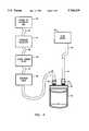
- FIG. 4is a schematic diagram illustrating dynamic gas flow through a widemouth specimen bottle and collection tube employed in an outgas test fixture in accordance with the present invention.
- FIG. 5is a top plan view of a custom made cap for the widemouth specimen bottle shown in FIG. 4.
- FIG. 6is a side elevation view in cross-section taken along the line 6--6 of FIG. 5.
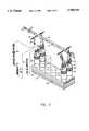
- FIG. 7is an exploded perspective view of an outgas test fixture constructed in accordance with the principles of the present invention.
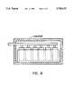
- FIG. 8is a side view partly in cross-section of the outgas test fixture of FIG. 7 blanketed by a layer of insulation.
- FIGS. 1 and 2show a heating block 20 that is employed in a multisample dynamic headspace sampler of the present invention.
- FIG. 1is a top plan view of the heating block 20, while FIG. 2 is a side elevation view.
- FIG. 2is partially broken away to show certain features of the heating block 20.
- the heating block 20may be made of 6061-T0 aluminum and the aluminum may be finished with a clear hard anodize. Typically the heating block 20 may be 16 inches long, 31/2 inches high and 51/2 inches wide.
- the heating block 20is provided with 12 equally dimensioned cups 21 machined into the top surface thereof.
- the cups 21may be 3.03 inches deep and 2.45 inches in diameter.
- Two blind holes 22are provided in the heating block 20 that are 0.252 inches in diameter and 2.9 inches in depth.
- FIG. 3shows a heating arrangement for use with the heating block 20 of FIGS. 1 and 2.
- a heating tape 25that is at least 43 inches long.
- the heating tape 25may be of a type referred to as Fibox heating tape sold by Barnstead & Thermolyn. barnstead & Thermolyn is located at 2555 Kerper Boulevard, Dubuque, Ia. 52001.
- the heating tape 25is electrically connected to a power supply 26.
- the power supply 26may be of the type called Mantle Minder II which is available from VWR Supply Company.
- a thermocouple 27which is accurate to ⁇ 2° Celsius over the range 50° to 200° C.
- the heating tape 25is wrapped around the heating block 20 and in intimate therma contact therewith.
- the heating tape 25is fastened securely to the outside of the heating block 20.
- the thermocouple 27is placed in one of the blind holes 22 of the heating block 20.
- the power supply 26is set for the desired temperature and the thermocouple 27 and the heating tape 25 maintain the heating block 20 to the desired temperature.
- FIG. 4is a schematic diagram illustrating dynamic gas flow through a bottle 30 having a capacity of 125 ml., and having a wide mouth.
- the top of the bottle 30is threaded and has a cap 31 fitted thereto.
- the cap 31is made of 6061-T0 aluminum and is knurled around the outside edge at 32.
- the cap 31is provided with threaded openings into which are screwed two fittings 33 of the type made by Swagelock and described as Ultra Torr.
- the fittings 33are 1/4 inch Ultra Torr 1/8 inch pipe threads.
- a tube 34is connected to one of the fittings 33.
- the tube 34may be made of stainless steel and may be a Part No. L4270123 manufactured by Perkin Elmer, for example, although there are many other tubes that will serve.
- a source 40 of ultra pure gasis provided.
- the gasshould be 99.999% pure, and may be either helium or nitrogen gas, for example.
- the gas source 40is connected to a pressure regulator 41 by a tubing 45.
- the pressure regulator 41may be a dual stage regulator, 0-30 psi.
- the pressure regulator 41is connected by a tubing 46 to a hydrocarbon filter 42 which may be a hydrocarbon trap Part No. 8C2-2445 which is supplied by Supelco, Inc.
- the filter 42is connected by a tubing 47 to a metering valve 44 which is, in turn, connected by a tubing 48 to one of the fittings 33 on the bottle 30.
- the metering valve 44may be an S series fine metering angle valve sold by Nupro as Part No. SS-SM2-S2-A.
- a flow meter 43is connected to the exit of the tube 34 by a tubing 49.
- the flow meter 43may be one identified as Humonics Veri-Flow 500 or equivalent.
- the tubing 49should also be 1/8 inch stainless steel or copper tubing.
- a specimen whose outgassing is to be testedis placed in the bottle 30, a suitable adsorbent is put into the tube 34.
- the gas pressure of the source 40is set between 10 and 15 psi.
- the flowis set to the desired level using the metering valve 44 while measuring the flow at the exit of the adsorbent tube 34 by means of the flow meter 43.
- Flow ratesare typically set between 50 and 250 ml. per minute.
- the specimen in the bottle 30is heated to cause outgassing and is held at an elevated temperature for between 3 anti 24 hours to collect a sample of the outgassed organic material in the tube 34.
- FIGS. 5 and 6illustrate details of the cap 31 shown in FIG. 4.
- FIG. 5is a top plan view of the cap 31, while FIG. 6 is a section view of FIG. 5.
- the cap 31has a knurled exterior at 32, and is provided with two threaded openings 35 that have a 1/8-27 NPT pipe thread.
- the interior of the cap 31is threaded with a 56 ⁇ 4.6 mm jar thread.
- the cap 31is provided with an O-ring 36.
- This O-ring 36typically has a thickness of 0.10 inches and an outer diameter of 2.28 inches, and is made of a fluoro-elastomer copolymer of hexafluoropropylene and vinylidene fluoride.
- this materialis used because it does not contaminate the outgas sample.
- These materialsare typically sold under the trade name Viton.
- a satisfactory O-ring 36is sold as Part No. 2-226,V75 by Ace Seal Co. It will be understood that it is necessary to use pure materials in the construction of the outgas test fixture of the present invention so as not to contribute unwanted materials to the outgassed test sample.
- FIG. 7is an exploded perspective view of an outgas test fixture for testing more than one specimen at a time. This is accomplished by the use of a manifold 50 to distribute gas to a plurality of bottles 30.
- the manifold 50comprises a stainless steel pipe 1/2 inch in diameter and 17 inches long.
- the manifoldis provided with 12 threaded holes 51, six holes 51 along each side of the manifold 50.
- the holes 51are threaded with a 1/8-27 NPT thread.
- a pipe cap 52is provided at each end of the manifold 50.
- One of the pipe caps 52is provided with a connector 53.
- This connector 53may be Part No. SS-200-1-2 manufactured by Swagelock and identified as a 1/8 inch tube--1/8 NPT connector.
- the connector 53is connected to the hydrocarbon filter 42 shown in FIG. 4. Each hole 51 is provided with a metering valve 44 as shown in FIG. 4.
- the metering valve 44is coupled to a port connector 54.
- the port connector 54may be Part No. SS-201-PC manufactured by Swagelock and described as a 1/8-1/8 port connector.
- the port connector 54is connected to a union 55.
- the union 55may be a Part No. SS4-UT-6-200 manufactured by Swagelock and described as a 1/8-1/4 tubing union.
- the union 55is connected to a flexible tubing 56.
- the flexible tubing 56may be a Part No. 321-4-X-4 manufactured by Cajon and described as stainless steel flexible tubing.
- the other end of the flexible tubing 56connects to an O-ring adapter 57.
- the O-ring adapter 57may be Part No. 3044-XOA manufactured by Cajon and described as an O-ring adapter.
- the O-ring adapter 57attaches to the fitting 33 on the bottle 30.
- An O-ring 58is compressed when the O-ring adapter is connected to the fitting 33.
- the O-ring 58is of a size to fit the O-ring adapter 57 and is also made of the elastomer described hereinabove and sold under the trade name Viton.
- a satisfactory O-ring 58is sold as Part No. 2-010,V75 by Ace Seal Co.
- the heating block 20is provided with cups 21 to receive the bottles 30.
- the heating tape 25is wrapped around the heating block 20.
- a compression band 60is disposed completely around the heating block 20 and clamps the heating tape 25 into intimate heat conductive contact with the heating block 20.
- the compression band 60may be a large radiator hose clamp as is used in the automotive industry, if desired.
- the outgas test fixture shown in FIG. 7may be used to quantitatively analyze the amount of off-gassed organic compounds over a broad temperature range of from 25° C. to 200° C.
- the choice of the appropriate adsorbent, temperatures, flow rate and method of analysisis up to the analyst and should be selected with the objective of obtaining the highest recovery and reproducibility for the target analytes under the chosen absorption and desorption conditions.
- the word "analyte”is used herein to mean the specific materials or off-gassed organic compounds that are to be analyzed.
- method blankrefers to an empty sample bottle 30 and its collection tube 34 that is tested along with the other samples.
- the method blankis tested in the identical manner as a sample, but it does not contain a sample.
- the method blankis also sometimes referred to as a "system" blank.
- the method blankindicates the baseline contamination level.
- spikerefers to placing a known amount of a compound or compounds in the sample bottle 30 and then analyzing the "spiked" collection tube 34 as if it were a sample.
- the measured amount of analyte or analytescan be compared to the known amount for a determination of the recovery factor for each analyte.
- the recovery factorequals ##EQU1##
- An internal standardis a known amount of a single compound that is intentionally added to all samples. The recovery factor has been determined for this compound. The overall reliability of the results from a particular sample run is assessed in part by how well the internal standard recovery results match with what is normally expected for that compound when the system is known to be functioning optimally.
- the insulationmay be any conventional insulation such as the fiberglass insulation batting used in the walls of houses and other buildings, for example. Record the time and temperature at desired intervals. Typically the target temperature can be reached within 30 minutes after adding the insulation. The temperature stability is usually ⁇ 2° C. Typical run times for sample collection are between 3 and 24 hours. End the experiment by reversing the order of the steps. Desorb the tube 34 and then analyze the contents with the appropriate instrumentation.
- Calibration procedureswill vary depending on the application. The following is a general calibration procedure. Prepare a calibration curve for each analyte and the internal standard on the analysis instrument. Use the calibration curve to quantify the amount of material desorbed from the adsorbent. Use the data from the spike run to determine the recovery for each target analyte.
- the measured values obtained from spikes and spike duplicatescan be used to assess the accuracy and precision of the measurement technique.
- Spike duplicatesare duplicate runs of the spike referred to hereinabove.
- 2500 nanograms of hexadecanewas used as an internal standard and collected at 80° C. for 3 hours. Each tube was then thermally desorbed and analyzed by a gas chromatograph equipped with a mass spectrometer detector. The results were as shown in Table I. Table I illustrates that for hexadecane, the recovery is 100% indicating that all of the hexadecane placed in the bottle 30 was collected into adsorbent in the tube 34 and accurately analyzed. The relative standard deviation (RSD) was below 2%, indicating a high degree of precision.
- Relative standard deviationis a mathematical way of describing the variation in a group of measurements or numbers. ##EQU2## With a stable compound and stable analysis conditions, the method, accuracy, and precision can be kept below ⁇ 5%.
- the objective for this improved outgas methodis to improve recovery precision and to improve dilution factor precision. That is to say the outgas method of the present invention has improved sensitivity relative to previous methods used. These two factors account for 33% of the random error, while the analysis steps contribute only 10%. A test with ⁇ 20% repeatability may be made possible by the method and apparatus of the present invention.
- the sample chamber bottle 30does not require cleaning. It is disposable.
- the sample bottle 30is sealed with Viton O-rings 36 which are made of a pure form of elastomer and do not contribute contaminates or contaminants to the sample.
- the heating block 20maintains temperatures to ⁇ 2° C.
- the tubes 34accommodate a variety of adsorbents. Either thermal or solvent desorption can be used for analysis by Fourier transform infrared spectroscopy, atomic absorption spectroscopy, ion chromatography, or supercritical fluid chromatography.
Landscapes
- Health & Medical Sciences (AREA)
- Life Sciences & Earth Sciences (AREA)
- Engineering & Computer Science (AREA)
- Biomedical Technology (AREA)
- Molecular Biology (AREA)
- Physics & Mathematics (AREA)
- Chemical & Material Sciences (AREA)
- Analytical Chemistry (AREA)
- Biochemistry (AREA)
- General Health & Medical Sciences (AREA)
- General Physics & Mathematics (AREA)
- Immunology (AREA)
- Pathology (AREA)
- Sampling And Sample Adjustment (AREA)
Abstract
Description
TABLE I ______________________________________ Amount of Spike Amount Measured % Avg hexadecane (ng) hexadecane (ng) Recovery Recov. % RSD ______________________________________ 2500 2476 99.04 2500 2495 99.8 2500 2568 102.72 100.52 1.91 ______________________________________
Claims (3)
Priority Applications (1)
| Application Number | Priority Date | Filing Date | Title |
|---|---|---|---|
| US08/780,883US5708219A (en) | 1995-09-12 | 1997-01-09 | Multisample dynamic headspace sampler |
Applications Claiming Priority (2)
| Application Number | Priority Date | Filing Date | Title |
|---|---|---|---|
| US08/527,292US5646334A (en) | 1995-09-12 | 1995-09-12 | Multisample dynamic headspace sampler |
| US08/780,883US5708219A (en) | 1995-09-12 | 1997-01-09 | Multisample dynamic headspace sampler |
Related Parent Applications (1)
| Application Number | Title | Priority Date | Filing Date |
|---|---|---|---|
| US08/527,292DivisionUS5646334A (en) | 1988-07-05 | 1995-09-12 | Multisample dynamic headspace sampler |
Publications (1)
| Publication Number | Publication Date |
|---|---|
| US5708219Atrue US5708219A (en) | 1998-01-13 |
Family
ID=24100878
Family Applications (7)
| Application Number | Title | Priority Date | Filing Date |
|---|---|---|---|
| US08/527,292Expired - Fee RelatedUS5646334A (en) | 1988-07-05 | 1995-09-12 | Multisample dynamic headspace sampler |
| US08/780,885Expired - Fee RelatedUS5773707A (en) | 1995-09-12 | 1997-01-09 | Calibration method for multisample dynamic headspace sampler |
| US08/780,883Expired - Fee RelatedUS5708219A (en) | 1995-09-12 | 1997-01-09 | Multisample dynamic headspace sampler |
| US08/780,886Expired - Fee RelatedUS5753791A (en) | 1995-09-12 | 1997-01-09 | Multisample dynamic headspace sampler |
| US08/892,011Expired - Fee RelatedUS5918289A (en) | 1995-09-12 | 1997-07-14 | Sample container for multisample dynamic headspace sampler |
| US08/892,013Expired - Fee RelatedUS5859356A (en) | 1995-09-12 | 1997-07-14 | Multisample dynamic headspace sampler |
| US08/892,012Expired - Fee RelatedUS5869741A (en) | 1995-09-12 | 1997-07-14 | Multisample dynamic headspace sampler |
Family Applications Before (2)
| Application Number | Title | Priority Date | Filing Date |
|---|---|---|---|
| US08/527,292Expired - Fee RelatedUS5646334A (en) | 1988-07-05 | 1995-09-12 | Multisample dynamic headspace sampler |
| US08/780,885Expired - Fee RelatedUS5773707A (en) | 1995-09-12 | 1997-01-09 | Calibration method for multisample dynamic headspace sampler |
Family Applications After (4)
| Application Number | Title | Priority Date | Filing Date |
|---|---|---|---|
| US08/780,886Expired - Fee RelatedUS5753791A (en) | 1995-09-12 | 1997-01-09 | Multisample dynamic headspace sampler |
| US08/892,011Expired - Fee RelatedUS5918289A (en) | 1995-09-12 | 1997-07-14 | Sample container for multisample dynamic headspace sampler |
| US08/892,013Expired - Fee RelatedUS5859356A (en) | 1995-09-12 | 1997-07-14 | Multisample dynamic headspace sampler |
| US08/892,012Expired - Fee RelatedUS5869741A (en) | 1995-09-12 | 1997-07-14 | Multisample dynamic headspace sampler |
Country Status (1)
| Country | Link |
|---|---|
| US (7) | US5646334A (en) |
Cited By (12)
| Publication number | Priority date | Publication date | Assignee | Title |
|---|---|---|---|---|
| US6065354A (en)* | 1999-05-20 | 2000-05-23 | Seagate Technology, Inc. | Spindle motor fixture for outgassing system |
| US6119534A (en)* | 1999-01-21 | 2000-09-19 | Seagate Technology, Inc. | Dynamic headspace outgassing system |
| US6205845B1 (en) | 1999-02-22 | 2001-03-27 | Seagate Technology Llc | Disc drive outgassing system |
| US20030063271A1 (en)* | 2001-08-17 | 2003-04-03 | Nicholes Mary Kristin | Sampling and measurement system with multiple slurry chemical manifold |
| US6925895B2 (en)* | 2001-07-02 | 2005-08-09 | Hampton Roads Sanitation District | Sample collection system |
| WO2008043281A1 (en)* | 2006-09-11 | 2008-04-17 | Li Yu E | Automatic gas sampler |
| US20100005856A1 (en)* | 2006-04-07 | 2010-01-14 | Kelman Limited | Apparatus for performing dissolved gas analysis |
| US20100186838A1 (en)* | 2009-01-28 | 2010-07-29 | Aeromaster Innovations Inc. | Alternating State Flow Valve |
| US20100276011A1 (en)* | 2009-01-28 | 2010-11-04 | Spitzer Jeffrey J | Alternating state flow valve |
| CN103604661A (en)* | 2013-10-30 | 2014-02-26 | 中国农业科学院农田灌溉研究所 | Apparatus used for soil sampling and moisture measuring in drip irrigation tests |
| CN110860185A (en)* | 2018-08-27 | 2020-03-06 | 杰智环境科技股份有限公司 | Switching valve and adsorption and desorption runner device and method capable of switching the flow direction of desorption gas |
| US20220276215A1 (en)* | 2019-10-08 | 2022-09-01 | Kurita Water Industries Ltd. | Water sampling device for water quality measurement |
Families Citing this family (25)
| Publication number | Priority date | Publication date | Assignee | Title |
|---|---|---|---|---|
| US5646334A (en)* | 1995-09-12 | 1997-07-08 | Seagate Technology, Inc. | Multisample dynamic headspace sampler |
| US6078030A (en)* | 1998-09-09 | 2000-06-20 | Millipore Corporation | Component heater for use in semiconductor manufacturing equipment |
| US6975944B1 (en) | 1999-09-28 | 2005-12-13 | Alpha Mos | Method and apparatus for monitoring materials used in electronics |
| US6499361B1 (en)* | 2000-02-18 | 2002-12-31 | Alkermes Controlled Therapeutics, Inc. | Method and apparatus for uniform sorbate equilibration of solid samples |
| JP3416121B2 (en)* | 2001-02-07 | 2003-06-16 | 日本たばこ産業株式会社 | Apparatus and method for extracting volatile components |
| AU146706S (en) | 2001-03-07 | 2002-02-04 | Zoltans Pool Products Pty Ltd | Flip-flop hammer valve part |
| WO2003043011A1 (en) | 2001-11-13 | 2003-05-22 | Seagate Technology Llc | Disc drive gas filling system |
| US6783871B2 (en)* | 2002-04-05 | 2004-08-31 | Agilent Technologies, Inc. | Direct bond of steel at low temperatures |
| US6925853B2 (en)* | 2002-10-24 | 2005-08-09 | Midwest Research Institute | Air quality sampler using solid phase coated material |
| EP1673620B1 (en)* | 2003-10-17 | 2008-02-13 | Perkinelmer Las, Inc. | Method of introducing standard gas into sample vessel |
| US7404311B2 (en)* | 2006-09-11 | 2008-07-29 | Guth Laboratories, Inc. | Breath test simulator |
| JP5170239B2 (en)* | 2007-05-15 | 2013-03-27 | 和光純薬工業株式会社 | Pressure manifold for equalizing pressure in an integrated PCR-CE microfluidic device |
| US8015888B2 (en)* | 2007-06-15 | 2011-09-13 | Hy-Energy, Llc | Thin-film sample holder |
| DE102009000391A1 (en)* | 2008-12-15 | 2010-06-17 | BAM Bundesanstalt für Materialforschung und -prüfung | Method and device for producing complex gas mixtures |
| WO2010083884A1 (en)* | 2009-01-22 | 2010-07-29 | Agilent Technologies, Inc. | Apparatus for generating small flow rates in a channel |
| US20120087834A1 (en)* | 2010-10-12 | 2012-04-12 | Wildcat Discovery Technologies | Apparatus for synthesis and assaying of materials with temperature control enclosure assembly |
| US8673224B2 (en) | 2010-10-12 | 2014-03-18 | Wildcat Discovery Technologies, Inc. | Apparatus for synthesis and assaying of materials |
| GB2504300A (en)* | 2012-07-24 | 2014-01-29 | Genevac Ltd | Apparatus and method for evaporating a solvent from a sample |
| US10866166B2 (en)* | 2018-07-25 | 2020-12-15 | Xplosafe, Llc | Sorbent and devices for capturing, stabilizing and recovering volatile and semi-volatile compounds |
| CN105424876A (en)* | 2015-11-04 | 2016-03-23 | 中国直升机设计研究所 | Calibrating device for fire extinguishing agent concentration measuring system |
| CN105445402B (en)* | 2016-01-07 | 2018-04-17 | 云南中烟工业有限责任公司 | A kind of ml headspace bottle for being used to remove sample moisture |
| EP3474311A1 (en)* | 2017-10-20 | 2019-04-24 | Tofwerk AG | Ion molecule reactor |
| US10923160B2 (en) | 2019-07-05 | 2021-02-16 | Seagate Technology Llc | Testing assembly for sealed hard disk drives |
| JP7445760B2 (en)* | 2019-11-27 | 2024-03-07 | シムライズ アーゲー | Apparatus and method for making analytical and sensory determinations of the release of active substances from release systems |
| USD1002865S1 (en)* | 2021-02-18 | 2023-10-24 | Agilent Technologies, Inc. | Headspace sampler |
Citations (6)
| Publication number | Priority date | Publication date | Assignee | Title |
|---|---|---|---|---|
| US3018788A (en)* | 1959-09-29 | 1962-01-30 | David B Perlis | Fluid branch switching system |
| US3092141A (en)* | 1961-11-22 | 1963-06-04 | Springfield Tool And Die Co In | Airflow control unit for aquariums |
| US3369405A (en)* | 1964-11-03 | 1968-02-20 | Phillips Petroleum Co | Sampling system |
| US3928711A (en)* | 1973-05-25 | 1975-12-23 | Lourdes Ind Inc | Manifold system for renewing cable pressure and valve arrangement therefor |
| US5469751A (en)* | 1994-05-25 | 1995-11-28 | Sentry Equipment Corp. | Manifolded sampling valve assembly |
| US5598869A (en)* | 1995-11-30 | 1997-02-04 | Robertshaw Controls Company | Pressure regulating unit |
Family Cites Families (17)
| Publication number | Priority date | Publication date | Assignee | Title |
|---|---|---|---|---|
| US2284147A (en)* | 1939-01-28 | 1942-05-26 | Standard Oil Co California | Method and apparatus for soil gas analysis |
| US2238832A (en)* | 1939-05-11 | 1941-04-15 | Albin H Thoren | Fishing lure |
| US2386832A (en)* | 1940-08-20 | 1945-10-16 | Cons Eng Corp | Method of obtaining soil gas samples |
| US3021034A (en)* | 1959-08-24 | 1962-02-13 | Maack Hans | Tamper protective closure |
| US3135411A (en)* | 1963-05-09 | 1964-06-02 | Wiley W Osborne | Vacuum sealing means |
| US3879044A (en)* | 1973-06-13 | 1975-04-22 | Du Pont | Reinforced elastomeric o-ring with improved compression set |
| US4046014A (en)* | 1975-06-20 | 1977-09-06 | Boehringer John R | Sealable activated charcoal gas sampler |
| US4214473A (en)* | 1978-12-18 | 1980-07-29 | The United States Of America As Represented By The United States Department Of Energy | Gaseous trace impurity analyzer and method |
| US4388272A (en)* | 1981-04-08 | 1983-06-14 | Northwestern University | Method and apparatus for precise control of vapor phase concentrations of volatile organics |
| US4489593A (en)* | 1982-09-09 | 1984-12-25 | Omicron Technology Corporation | Method and apparatus for determining the amount of gas adsorbed or desorbed from a solid |
| CA1223461A (en)* | 1985-02-08 | 1987-06-30 | Andre H. Lawrence | Method and apparatus for the introduction of a vapourized sample into an analytical test apparatus |
| US4865996A (en)* | 1986-07-28 | 1989-09-12 | Brunswick Corporation | Sorption/desorption method and apparatus |
| US4926356A (en)* | 1988-02-29 | 1990-05-15 | The Boeing Company | Test apparatus for measuring heat release of certain materials |
| US5646334A (en)* | 1995-09-12 | 1997-07-08 | Seagate Technology, Inc. | Multisample dynamic headspace sampler |
| US4970891A (en)* | 1989-12-26 | 1990-11-20 | Ethyl Corporation | Apparatus for measuring gaseous impurity in solids |
| US5100624A (en)* | 1990-06-04 | 1992-03-31 | Fmc Corporation | Apparatus for determining the stability of a peroxygen |
| US5326708A (en)* | 1992-02-28 | 1994-07-05 | Lewis Douglas E | Forensically acceptable determinations of gestational fetal exposure to drugs and other chemical agents |
- 1995
- 1995-09-12USUS08/527,292patent/US5646334A/ennot_activeExpired - Fee Related
- 1997
- 1997-01-09USUS08/780,885patent/US5773707A/ennot_activeExpired - Fee Related
- 1997-01-09USUS08/780,883patent/US5708219A/ennot_activeExpired - Fee Related
- 1997-01-09USUS08/780,886patent/US5753791A/ennot_activeExpired - Fee Related
- 1997-07-14USUS08/892,011patent/US5918289A/ennot_activeExpired - Fee Related
- 1997-07-14USUS08/892,013patent/US5859356A/ennot_activeExpired - Fee Related
- 1997-07-14USUS08/892,012patent/US5869741A/ennot_activeExpired - Fee Related
Patent Citations (6)
| Publication number | Priority date | Publication date | Assignee | Title |
|---|---|---|---|---|
| US3018788A (en)* | 1959-09-29 | 1962-01-30 | David B Perlis | Fluid branch switching system |
| US3092141A (en)* | 1961-11-22 | 1963-06-04 | Springfield Tool And Die Co In | Airflow control unit for aquariums |
| US3369405A (en)* | 1964-11-03 | 1968-02-20 | Phillips Petroleum Co | Sampling system |
| US3928711A (en)* | 1973-05-25 | 1975-12-23 | Lourdes Ind Inc | Manifold system for renewing cable pressure and valve arrangement therefor |
| US5469751A (en)* | 1994-05-25 | 1995-11-28 | Sentry Equipment Corp. | Manifolded sampling valve assembly |
| US5598869A (en)* | 1995-11-30 | 1997-02-04 | Robertshaw Controls Company | Pressure regulating unit |
Cited By (19)
| Publication number | Priority date | Publication date | Assignee | Title |
|---|---|---|---|---|
| US6119534A (en)* | 1999-01-21 | 2000-09-19 | Seagate Technology, Inc. | Dynamic headspace outgassing system |
| US6324923B1 (en) | 1999-01-21 | 2001-12-04 | Seagate Technology Llc | Dynamic headspace outgassing system |
| US6205845B1 (en) | 1999-02-22 | 2001-03-27 | Seagate Technology Llc | Disc drive outgassing system |
| US6065354A (en)* | 1999-05-20 | 2000-05-23 | Seagate Technology, Inc. | Spindle motor fixture for outgassing system |
| US6925895B2 (en)* | 2001-07-02 | 2005-08-09 | Hampton Roads Sanitation District | Sample collection system |
| US20030063271A1 (en)* | 2001-08-17 | 2003-04-03 | Nicholes Mary Kristin | Sampling and measurement system with multiple slurry chemical manifold |
| US8347687B2 (en)* | 2006-04-07 | 2013-01-08 | Kelman Limited | Apparatus for performing dissolved gas analysis |
| US20100005856A1 (en)* | 2006-04-07 | 2010-01-14 | Kelman Limited | Apparatus for performing dissolved gas analysis |
| WO2008043281A1 (en)* | 2006-09-11 | 2008-04-17 | Li Yu E | Automatic gas sampler |
| US20100186838A1 (en)* | 2009-01-28 | 2010-07-29 | Aeromaster Innovations Inc. | Alternating State Flow Valve |
| US20100276011A1 (en)* | 2009-01-28 | 2010-11-04 | Spitzer Jeffrey J | Alternating state flow valve |
| US8752582B2 (en) | 2009-01-28 | 2014-06-17 | Aeromaster Innovations, Inc. | Alternative state flow valve |
| US9116522B2 (en) | 2009-01-28 | 2015-08-25 | Aeromaster Innovations, Inc. | Alternating state flow valve |
| CN103604661A (en)* | 2013-10-30 | 2014-02-26 | 中国农业科学院农田灌溉研究所 | Apparatus used for soil sampling and moisture measuring in drip irrigation tests |
| CN103604661B (en)* | 2013-10-30 | 2015-08-19 | 中国农业科学院农田灌溉研究所 | A kind of drip irrigation test soil sample and device for measuring moisture |
| CN110860185A (en)* | 2018-08-27 | 2020-03-06 | 杰智环境科技股份有限公司 | Switching valve and adsorption and desorption runner device and method capable of switching the flow direction of desorption gas |
| CN110860185B (en)* | 2018-08-27 | 2021-07-27 | 杰智环境科技股份有限公司 | Switching valve and adsorption and desorption runner device and method capable of switching the flow direction of desorption gas |
| US20220276215A1 (en)* | 2019-10-08 | 2022-09-01 | Kurita Water Industries Ltd. | Water sampling device for water quality measurement |
| US12130273B2 (en)* | 2019-10-08 | 2024-10-29 | Kurita Water Industries Ltd. | Water sampling device for water quality measurement |
Also Published As
| Publication number | Publication date |
|---|---|
| US5859356A (en) | 1999-01-12 |
| US5753791A (en) | 1998-05-19 |
| US5773707A (en) | 1998-06-30 |
| US5646334A (en) | 1997-07-08 |
| US5918289A (en) | 1999-06-29 |
| US5869741A (en) | 1999-02-09 |
Similar Documents
| Publication | Publication Date | Title |
|---|---|---|
| US5708219A (en) | Multisample dynamic headspace sampler | |
| US11467135B2 (en) | Online measuring system, method and application for semi-volatile organic compound in gas phase | |
| KR101874651B1 (en) | Flow regulating system and monitoring device comprising said flow regulating system for the detection of air borne analytes | |
| JP4283047B2 (en) | Molecular contamination monitoring system and molecular contamination monitoring method | |
| US7430928B2 (en) | Method and apparatus for concentrating vapors for analysis | |
| CN107884306B (en) | Adsorption testing method and device | |
| US6119534A (en) | Dynamic headspace outgassing system | |
| US7854158B2 (en) | Systems and methods for measurement and analysis of pipeline contaminants | |
| US5773713A (en) | Environmental monitoring of organic compounds | |
| JP2010515040A (en) | Apparatus and method for combined measurement for comprehensive and continuous tracking of trace amounts of tar present in a gas stream | |
| US8664004B2 (en) | Method for analysis of contaminants in a process fluid stream | |
| EP1854906A2 (en) | Analysis of a reactive gas such as silane for particle generating impurities | |
| EP3625559A1 (en) | Automated thermal desorption systems and methods | |
| Handley et al. | Determination of the natural abundances of the stable isotopes of 15 N and 13 C by mass spectrometry: A simplified manual method for the preparation of N 2 and CO 2 | |
| Dewulf et al. | Measurement of Atmospheric Monocyclic Aromatic Hydrocarbons and Chlorinated C1-and C2-Hydrocarbons at NG. M− 3 Concentration Levels | |
| CN210465350U (en) | On-site rapid detection device for VOCs in upholstered furniture | |
| US20010025524A1 (en) | Method of evaluating adsorption of contaminant on solid surface | |
| Haunold et al. | An improved sampling strategy for the measurement of VOCs in air, based on cooled sampling and analysis by thermodesorption-GC-MS/FID | |
| CN210465351U (en) | VOCs on-site rapid detection device in wooden furniture | |
| CN118209581B (en) | Fluid thermal property detection device and method | |
| Liaw et al. | Measurement of C2-C6 Nonmethane Hydrocarbons in the Background Atmosphere of Taiwan by Using the Canister-Gas Chromatography Method | |
| Holmes et al. | Purge gases for the removal of airborne molecular contamination during the storage and transport of silicon wafers | |
| CA2722722C (en) | Polar component detection | |
| Martin et al. | Analysis of Trace Volatiles by Gas Chromatograph/Mass Spectrometer Data System. | |
| Pedersen | Glass micro preconcentrators for point of care diagnostics: Low cost fabrication techniques and evaluation methods |
Legal Events
| Date | Code | Title | Description |
|---|---|---|---|
| AS | Assignment | Owner name:SEAGATE TECHNOLOGY LLC, CALIFORNIA Free format text:ASSIGNMENT OF ASSIGNORS INTEREST;ASSIGNOR:SEAGATE TECHNOLOGY, INC.;REEL/FRAME:011077/0319 Effective date:20000728 | |
| FEPP | Fee payment procedure | Free format text:PAYER NUMBER DE-ASSIGNED (ORIGINAL EVENT CODE: RMPN); ENTITY STATUS OF PATENT OWNER: LARGE ENTITY Free format text:PAYOR NUMBER ASSIGNED (ORIGINAL EVENT CODE: ASPN); ENTITY STATUS OF PATENT OWNER: LARGE ENTITY | |
| AS | Assignment | Owner name:THE CHASE MANHATTAN BANK, AS COLLATERAL AGENT, NEW Free format text:SECURITY AGREEMENT;ASSIGNOR:SEAGATE TECHNOLOGY LLC;REEL/FRAME:011461/0001 Effective date:20001122 | |
| FPAY | Fee payment | Year of fee payment:4 | |
| AS | Assignment | Owner name:JPMORGAN CHASE BANK, AS COLLATERAL AGENT, NEW YORK Free format text:SECURITY AGREEMENT;ASSIGNOR:SEAGATE TECHNOLOGY LLC;REEL/FRAME:013177/0001 Effective date:20020513 Owner name:JPMORGAN CHASE BANK, AS COLLATERAL AGENT,NEW YORK Free format text:SECURITY AGREEMENT;ASSIGNOR:SEAGATE TECHNOLOGY LLC;REEL/FRAME:013177/0001 Effective date:20020513 | |
| FPAY | Fee payment | Year of fee payment:8 | |
| AS | Assignment | Owner name:SEAGATE TECHNOLOGY LLC, CALIFORNIA Free format text:RELEASE OF SECURITY INTERESTS IN PATENT RIGHTS;ASSIGNOR:JPMORGAN CHASE BANK, N.A. (FORMERLY KNOWN AS THE CHASE MANHATTAN BANK AND JPMORGAN CHASE BANK), AS ADMINISTRATIVE AGENT;REEL/FRAME:016945/0679 Effective date:20051130 | |
| AS | Assignment | Owner name:WELLS FARGO BANK, NATIONAL ASSOCIATION, AS COLLATERAL AGENT AND SECOND PRIORITY REPRESENTATIVE, CALIFORNIA Free format text:SECURITY AGREEMENT;ASSIGNORS:MAXTOR CORPORATION;SEAGATE TECHNOLOGY LLC;SEAGATE TECHNOLOGY INTERNATIONAL;REEL/FRAME:022757/0017 Effective date:20090507 Owner name:JPMORGAN CHASE BANK, N.A., AS ADMINISTRATIVE AGENT AND FIRST PRIORITY REPRESENTATIVE, NEW YORK Free format text:SECURITY AGREEMENT;ASSIGNORS:MAXTOR CORPORATION;SEAGATE TECHNOLOGY LLC;SEAGATE TECHNOLOGY INTERNATIONAL;REEL/FRAME:022757/0017 Effective date:20090507 Owner name:JPMORGAN CHASE BANK, N.A., AS ADMINISTRATIVE AGENT Free format text:SECURITY AGREEMENT;ASSIGNORS:MAXTOR CORPORATION;SEAGATE TECHNOLOGY LLC;SEAGATE TECHNOLOGY INTERNATIONAL;REEL/FRAME:022757/0017 Effective date:20090507 Owner name:WELLS FARGO BANK, NATIONAL ASSOCIATION, AS COLLATE Free format text:SECURITY AGREEMENT;ASSIGNORS:MAXTOR CORPORATION;SEAGATE TECHNOLOGY LLC;SEAGATE TECHNOLOGY INTERNATIONAL;REEL/FRAME:022757/0017 Effective date:20090507 | |
| REMI | Maintenance fee reminder mailed | ||
| LAPS | Lapse for failure to pay maintenance fees | ||
| STCH | Information on status: patent discontinuation | Free format text:PATENT EXPIRED DUE TO NONPAYMENT OF MAINTENANCE FEES UNDER 37 CFR 1.362 | |
| FP | Lapsed due to failure to pay maintenance fee | Effective date:20100113 | |
| AS | Assignment | Owner name:MAXTOR CORPORATION, CALIFORNIA Free format text:RELEASE;ASSIGNOR:JPMORGAN CHASE BANK, N.A., AS ADMINISTRATIVE AGENT;REEL/FRAME:025662/0001 Effective date:20110114 Owner name:SEAGATE TECHNOLOGY HDD HOLDINGS, CALIFORNIA Free format text:RELEASE;ASSIGNOR:JPMORGAN CHASE BANK, N.A., AS ADMINISTRATIVE AGENT;REEL/FRAME:025662/0001 Effective date:20110114 Owner name:SEAGATE TECHNOLOGY INTERNATIONAL, CALIFORNIA Free format text:RELEASE;ASSIGNOR:JPMORGAN CHASE BANK, N.A., AS ADMINISTRATIVE AGENT;REEL/FRAME:025662/0001 Effective date:20110114 Owner name:SEAGATE TECHNOLOGY LLC, CALIFORNIA Free format text:RELEASE;ASSIGNOR:JPMORGAN CHASE BANK, N.A., AS ADMINISTRATIVE AGENT;REEL/FRAME:025662/0001 Effective date:20110114 | |
| AS | Assignment | Owner name:SEAGATE TECHNOLOGY LLC, CALIFORNIA Free format text:TERMINATION AND RELEASE OF SECURITY INTEREST IN PATENT RIGHTS;ASSIGNOR:WELLS FARGO BANK, NATIONAL ASSOCIATION, AS COLLATERAL AGENT AND SECOND PRIORITY REPRESENTATIVE;REEL/FRAME:030833/0001 Effective date:20130312 Owner name:SEAGATE TECHNOLOGY INTERNATIONAL, CAYMAN ISLANDS Free format text:TERMINATION AND RELEASE OF SECURITY INTEREST IN PATENT RIGHTS;ASSIGNOR:WELLS FARGO BANK, NATIONAL ASSOCIATION, AS COLLATERAL AGENT AND SECOND PRIORITY REPRESENTATIVE;REEL/FRAME:030833/0001 Effective date:20130312 Owner name:SEAGATE TECHNOLOGY US HOLDINGS, INC., CALIFORNIA Free format text:TERMINATION AND RELEASE OF SECURITY INTEREST IN PATENT RIGHTS;ASSIGNOR:WELLS FARGO BANK, NATIONAL ASSOCIATION, AS COLLATERAL AGENT AND SECOND PRIORITY REPRESENTATIVE;REEL/FRAME:030833/0001 Effective date:20130312 Owner name:EVAULT INC. (F/K/A I365 INC.), CALIFORNIA Free format text:TERMINATION AND RELEASE OF SECURITY INTEREST IN PATENT RIGHTS;ASSIGNOR:WELLS FARGO BANK, NATIONAL ASSOCIATION, AS COLLATERAL AGENT AND SECOND PRIORITY REPRESENTATIVE;REEL/FRAME:030833/0001 Effective date:20130312 |