US5707881A - Test structure and method for performing burn-in testing of a semiconductor product wafer - Google Patents
Test structure and method for performing burn-in testing of a semiconductor product waferDownload PDFInfo
- Publication number
- US5707881A US5707881AUS08/706,888US70688896AUS5707881AUS 5707881 AUS5707881 AUS 5707881AUS 70688896 AUS70688896 AUS 70688896AUS 5707881 AUS5707881 AUS 5707881A
- Authority
- US
- United States
- Prior art keywords
- integrated circuits
- conductive
- layer
- segmented
- wafer
- Prior art date
- Legal status (The legal status is an assumption and is not a legal conclusion. Google has not performed a legal analysis and makes no representation as to the accuracy of the status listed.)
- Expired - Lifetime
Links
Images


Classifications
- G—PHYSICS
- G01—MEASURING; TESTING
- G01R—MEASURING ELECTRIC VARIABLES; MEASURING MAGNETIC VARIABLES
- G01R31/00—Arrangements for testing electric properties; Arrangements for locating electric faults; Arrangements for electrical testing characterised by what is being tested not provided for elsewhere
- G01R31/28—Testing of electronic circuits, e.g. by signal tracer
- G01R31/282—Testing of electronic circuits specially adapted for particular applications not provided for elsewhere
- G01R31/2831—Testing of materials or semi-finished products, e.g. semiconductor wafers or substrates
- G—PHYSICS
- G01—MEASURING; TESTING
- G01R—MEASURING ELECTRIC VARIABLES; MEASURING MAGNETIC VARIABLES
- G01R31/00—Arrangements for testing electric properties; Arrangements for locating electric faults; Arrangements for electrical testing characterised by what is being tested not provided for elsewhere
- G01R31/28—Testing of electronic circuits, e.g. by signal tracer
- G01R31/2851—Testing of integrated circuits [IC]
- G01R31/2886—Features relating to contacting the IC under test, e.g. probe heads; chucks
- G—PHYSICS
- G01—MEASURING; TESTING
- G01R—MEASURING ELECTRIC VARIABLES; MEASURING MAGNETIC VARIABLES
- G01R31/00—Arrangements for testing electric properties; Arrangements for locating electric faults; Arrangements for electrical testing characterised by what is being tested not provided for elsewhere
- G01R31/28—Testing of electronic circuits, e.g. by signal tracer
- G01R31/2851—Testing of integrated circuits [IC]
- G01R31/2855—Environmental, reliability or burn-in testing
- G01R31/2856—Internal circuit aspects, e.g. built-in test features; Test chips; Measuring material aspects, e.g. electro migration [EM]
- H—ELECTRICITY
- H01—ELECTRIC ELEMENTS
- H01L—SEMICONDUCTOR DEVICES NOT COVERED BY CLASS H10
- H01L2224/00—Indexing scheme for arrangements for connecting or disconnecting semiconductor or solid-state bodies and methods related thereto as covered by H01L24/00
- H01L2224/01—Means for bonding being attached to, or being formed on, the surface to be connected, e.g. chip-to-package, die-attach, "first-level" interconnects; Manufacturing methods related thereto
- H01L2224/10—Bump connectors; Manufacturing methods related thereto
- H01L2224/15—Structure, shape, material or disposition of the bump connectors after the connecting process
- H01L2224/16—Structure, shape, material or disposition of the bump connectors after the connecting process of an individual bump connector
- H01L2224/161—Disposition
- H01L2224/16151—Disposition the bump connector connecting between a semiconductor or solid-state body and an item not being a semiconductor or solid-state body, e.g. chip-to-substrate, chip-to-passive
- H01L2224/16221—Disposition the bump connector connecting between a semiconductor or solid-state body and an item not being a semiconductor or solid-state body, e.g. chip-to-substrate, chip-to-passive the body and the item being stacked
- H01L2224/16225—Disposition the bump connector connecting between a semiconductor or solid-state body and an item not being a semiconductor or solid-state body, e.g. chip-to-substrate, chip-to-passive the body and the item being stacked the item being non-metallic, e.g. insulating substrate with or without metallisation
- H—ELECTRICITY
- H01—ELECTRIC ELEMENTS
- H01L—SEMICONDUCTOR DEVICES NOT COVERED BY CLASS H10
- H01L2224/00—Indexing scheme for arrangements for connecting or disconnecting semiconductor or solid-state bodies and methods related thereto as covered by H01L24/00
- H01L2224/73—Means for bonding being of different types provided for in two or more of groups H01L2224/10, H01L2224/18, H01L2224/26, H01L2224/34, H01L2224/42, H01L2224/50, H01L2224/63, H01L2224/71
- H01L2224/732—Location after the connecting process
- H01L2224/73251—Location after the connecting process on different surfaces
- H01L2224/73253—Bump and layer connectors
- H—ELECTRICITY
- H01—ELECTRIC ELEMENTS
- H01L—SEMICONDUCTOR DEVICES NOT COVERED BY CLASS H10
- H01L2924/00—Indexing scheme for arrangements or methods for connecting or disconnecting semiconductor or solid-state bodies as covered by H01L24/00
- H01L2924/15—Details of package parts other than the semiconductor or other solid state devices to be connected
- H01L2924/151—Die mounting substrate
- H01L2924/153—Connection portion
- H01L2924/1531—Connection portion the connection portion being formed only on the surface of the substrate opposite to the die mounting surface
- H01L2924/15311—Connection portion the connection portion being formed only on the surface of the substrate opposite to the die mounting surface being a ball array, e.g. BGA
Definitions
- the present inventionrelates generally to semiconductor product testing, and more particularly, to wafer-level burn-in of semiconductor wafers using a wafer level test apparatus and methodology.
- Integrated circuitsare formed in fabrication facilities by making hundreds to thousands of integrated circuits on a single integrated circuit wafer. Currently, these integrated circuits are diced or cut from the semiconductor wafer and packaged in integrated circuit packages. After being packaged, the integrated circuits are subjected to functional testing and burn-in operations to ensure that each packaged integrated circuit is functioning properly and reliably. A problem with this process is that all of the integrated circuits on the semiconductor wafer that are diced and packaged may not be functioning after final testing. These non-functioning integrated circuits on the wafer are none the less packaged and tested along with functioning integrated circuits on the wafer, incurring additional wasted cost and manufacturing time. It would be advantageous to determine at a wafer level which integrated circuits are functional and non-functional before the time and cost of integrated circuit packaging is incurred.
- One method for performing wafer level testing to save time and packaging costsis to form sacrificial wafer level conductive layers on top of the product wafers. These sacrificial test conductive layers are then used to burn-in and test all integrated circuits on an entire wafer prior to dicing or cutting the integrated circuits from the wafer. By performing this wafer level test, integrated circuits which are non-functional can be flagged early in the process and can be discarded without incurring the cost and additional time of the packaging operation.
- sacrificial wafer level test layers on top of a product wafermay not be an optimal process. These additional layers added to the top of a product wafer add process complexity to the manufacture of the product wafers. Therefore, these sacrificial wafers reduce the yield of the product wafer in an unnecessary fashion. Furthermore, the manufacture of semiconductor wafers is performed in the clean room which is substantially free of contamination. On the other hand, testing of the entire wafer is performed in an environment that is substantially unclean. Therefore, once the test operation has been performed in an unclean environment the wafer must be transferred back into a clean environment to perform removal of the sacrificial wafer level test layer. This process of bringing a wafer from a contaminated area into a clean area may result in the clean area ultimately being contaminated whereby other wafers being manufactured in the clean area are going to be impacted in terms of yield.
- the deposition of sacrificial metallic layers on a wafer level scaledoes not allow one to perform intelligent testing of an integrated circuit. Most of the testing performed by this wafer scale sacrificial deposition is serial in nature and is not intelligent in terms of activity circuitry.
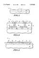
- FIGS. 1-7illustrate, in a cross-sectional diagram, a process which is used to form a wafer level test structure in accordance with the present invention.
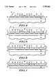
- FIG. 8illustrates, in a cross-sectional diagram, the test structure of FIG. 7 coupled to a product wafer so that burn-in operation can be performed on the product wafer in accordance with the present invention.
- FIG. 9illustrates, in a top perspective view, the test structure previously illustrated in a cross-sectional manner via FIG. 7.
- FIG. 10illustrates, in a flow chart, a method for manufacture of a test structure, in accordance with one embodiment of the present invention, as illustrated in FIGS. 1-7.
- FIG. 11illustrates, in a flow chart, a method for using the test structure according to one embodiment of the present invention, illustrated in FIG. 7 to test a product wafer in accordance with the present invention.
- FIG. 12illustrates, in a cross sectional diagram, another embodiment of FIG. 2 wherein the final device of FIG. 7 will be a multi-chip module (MCM).
- MCMmulti-chip module
- the present inventionis a test structure and methodology for testing an entire semiconductor wafer where the semiconductor wafer contains a plurality of product integrated circuits.
- the test apparatushas a base layer which typically comprises a silicon wafer mold upon which is formed a thin film signal distribution layer.
- the signal distribution layercontains: (1) one or more levels of metal to route electrical signals; (2) optional interconnects and contacts as needed between metal layers of the thin film signal distribution layer; (3) and dielectric encapsulation as needed to provide electric isolation for (1) and (2).
- Conductive contact areasare located on a top and bottom surface of the thin film signal distribution layer so that electrical signals can be sent between the top surface of thin film signal distribution layer and the bottom surface of the thin film signal distribution layer.
- a plurality of test integrated circuitsare placed onto the thin film signal distribution layer so that conductive bumps on a top surface of the plurality of test integrated circuits are electrically coupled to the contact areas located on a top surface of the thin film signal distribution layer.
- the plurality of test integrated circuitsare stabilized and mechanically strengthened by a silicon backing wafer attached to backsides of the plurality of test integrated circuits.
- Product wafersare coupled one at time to the plurality of test integrated through the conductive elements of the thin film signal layer.
- the product integrated circuits of the product wafersare tested via power, ground, and other optional electrical signals communicated from the plurality of test integrated circuits the product wafer through the thin film signal distribution layer.
- This processallows engineers to identify known good die while in wafer form where the known good die can be segregated from "bad" die for further manufacturing processes.
- This wafer level known good die techniqueprevents inoperative "bad” die from being further processed.
- the identification of known good die, before dicing the integrated circuits from the wafersaves packaging time, increases good die throughput, and reduces wasted manufacturing costs.
- this wafer level test mechanismsignificantly aids in the manufacture of multi-chip-modules (MCM) by eliminating inoperative die from subsequent processing.
- MCMmulti-chip-modules
- FIGS. 1-11The invention can be understood with reference to FIGS. 1-11.
- the present inventionis a method and apparatus used to perform wafer level burn-in.
- the method and apparatususe a wafer-level test structure assembled from individually-tested and singulated test die. Note that the present invention is applicable to more than wafer burn-in and includes any integrated circuit testing, functional and parametric test, static burn-in testing, and dynamic burn-in testing.
- the method for fabricating the test structure for use in wafer level burn-in/testis illustrated in FIGS. 1-7.
- a signal distribution film 14is built on top of a mold 12.
- Mold 12is preferably a blank silicon wafer of the same size as the wafer which is to subsequently undergo burn-in/testing.
- the test 10 taught hereincan be designed to accommodate any wafer size (e.g. 5", 6", 8", 12", etc.).
- the wafer mold 12is used to provide mechanical support on which the thin film 14 can be formed without damage.
- Using the wafer 12also allows layer 14 to be formed in a cost effective manner with high yield by using many conventional integrated circuit (IC) processing steps.
- ICintegrated circuit
- the layer 14is formed on top of the mold 12 using conventional integrated circuits (IC) processing and materials, such as polyimide, silicon dioxide, copper, aluminum, silicides, BPSG, PSG, polysilicon, etc.. Specifically, the layer 14 is manufactured using conventional film deposition, lithographic processing, and etching using the mold 12 as a temporary substrate. An example of layer 14 is illustrated in a magnified portion 5 of FIG. 2, which is also illustrated in a non-magnified manner in FIG. 1.
- ICintegrated circuits
- FIG. 2which contains a magnified portion of FIG. 1, one possible embodiment for layer 14 is illustrated.
- a photo-imageable polyimide layer 16is spun on the silicon mold wafer 12 to begin formation of the signal distribution film 14. Openings are then patterned through the layer 16 as illustrated in FIG. 2. The openings in layer 16 are formed to match a C4 conductive bump pattern or a subset C4 pattern of a product wafer 44 containing product integrated circuits (illustrated in FIG. 8). The polyimide layer is developed resulting in dielectric layer 16 which has openings as illustrated in FIG. 2. It should be noted that other technology other that C4 bump processing may be used herein.
- a copper layer, or like metallic material 18,is then deposited over the mold 12 and the layer 16.
- Layer 18will be used to form a first patterned metal conductive layer 18. It is important to note that some metallic layers taught herein will be exposed to solder processing in order to couple to C4 bumps, leads, or the conductive elements. The layers exposed to solder processing should be copper or a like metallic material to which solder can adequately adhere.
- Conductive layer 18is therefore a first layer of metal which forms conductive interconnections and conductive contacts as illustrated in FIG. 2. Conductive contact of layer 18 are areas of layer 18 which fill the openings in layer 16 within FIG. 2. If a single metal thin film 14 is desired, processing can stop here with an optional dielectric capping layer on top of layer 18.
- a multi-metal-level structureis desired (single metal structures for layer 14 may not suffice in some applications), then further processing iterations may be performed to build further upon test structure 10 in FIG. 2.
- This further processingoptionally forms the additional layer of dielectric portions 20, conductive layer 22, and optional passivation layer 24 to build the desired multi-level metal structure.
- passivation layer 24is acts as a solder mask to define the area of solder wetting.
- subsequent optional C4 bump underfillmay reduce the need for a final passivation layer 24 in some embodiments.
- conductive portions 22will form contacts for connections to a test integrated circuits as illustrated in subsequent FIG. 3.
- the layer 18will contact to the C4 bump pattern of a product wafer 44 (remember that the mold 12 is a temporary support structure).
- Optional passivation layer 24completes formation of the signal distribution layer 14.
- the dielectric layers 16, 20, and 24 of FIG. 2are used to prevent inadvertent electrical short circuits when testing product wafers. Note that alternate embodiments may incorporate any number of layers of dielectric and metal to form layer 14. Typically metal portions 18 and 22 would be copper but other metals, semiconductors, and the like may be incorporated into the layer 14 as conductive members. Collectively, dielectric portions 16, 20 and 24 and conductive portions 18 and 22 form signal distribution film 14.
- “smart”, “active”, and/or “passive” circuitsmay formed within the film 14.
- the easiest structures to form within film 14are “passive” circuit elements. Passive circuit elements are diodes, resistors, capacitors, inductors, and the like. These devices can be used to form isolation, restrict current flow, divide voltages, decouple noise, etc..
- a parallel plate capacitorcan be made with a first electrode in layer 22 and a second electrode in layer 18.
- Resistorscan be made by depositing polysilicon between layers 18 and 22, etc..
- smart circuitslike D flip-flops, multiplexers, transistors, logic gates, and the like, can be formed in silicon on insulator (SOI) substrates 12 and coupled to perform test functions within the test structure 10.
- SOIsilicon on insulator
- Polysilicon layerscan be deposited onto mold 12 to form thin film transistors (TFTs) which can perform switching functions. Anything that is possible for conventional IC formation is possible for the thin film 14.
- FIG. 3illustrates further steps in the fabrication of test structure 10 where individual "good” test die 28-34 are attached to signal distribution film 14.
- Goodmeans that the die 28-34 have been tested to a significant extent and determined to be fully operational.
- individual good test die 28-34are exemplary of a plurality of individual good test die incorporated in test structure 10. Anywhere from a few to hundreds/thousands of test die 28-34 can be arranged over the two dimensional surface of the mold 12 and film 14 (see FIG. 9).
- Die 28-34are used for power control, current control, signal stimulus and generation for programmed control of burn-in testing, speed path testing, (JTAG) testing, Built In Self Test (BIST) testing, stuck-at-fault testing, and like test and monitored burn-in procedures/control.
- Each integrated circuit in die 28-34may either be the same functional die or different die which perform different functions in the test system.
- each die 28-34can be a microcontroller or ASIC responsible for test product integrated circuits and communicating test information between an external tester and the product ICs.
- good die 28-34are attached to signal distribution film 14 using standard C4 conductive bumps 26 which are formed using standard C4 bump processing or like bump processes.
- standard C4 conductive bumps 26which are formed using standard C4 bump processing or like bump processes.
- Conductive contact areas(illustrated as bumps 26 in FIG. 3) on each of the good die 28-34 are in contact with conductive areas 22 as illustrated in FIG. 2. This contact is typically made permanent by solder or like procedures.
- the contact between conductive contact areas on die 28-34helps to maintain the mechanical integrity and alignment between good die 28-34 and conductive materials 18 from FIG. 2.
- the materials used to manufacture the layer 14should be similar to the materials used to form the integrated circuits of good die 28-34 in terms of thermal coefficient of expansion so that stress, alignment, temperature variation, etc., are not problems within the overall test structure 10.
- under fill material 36is applied between good die 28-34 and signal distribution film 14.
- under fill materialis applied in the spaces between good die 28-34 where this material 36 fills gaps located between the conductive bump contact areas. This filling phenomenon is performed by capillary action.
- the under fill naterial 36is typically a low viscosity epoxy-like material.
- conductive leads 40are attached to exposed conductive contact areas 22 of signal distribution film 14 (see FIG. 2 which shows some example contact areas). Note that contact areas for C4 bump and contact areas for leads may be of substantially different sizes.
- leads 40are connected to power supplies and input/output signals from an external tester to allow for test communication from the external tester to the die 28-34 and on to the product wafer 44 (see FIG. 8). Note that leads 40 are illustrated in FIG. 4 as having a bent shape, however, many different types and shaped of leads can be formed in FIG. 5. In summary, leads 40 allow power supply and I/O signals to be supplied to test structure 10.
- backing support wafer 39is attached to a back side of die 28-34 providing support, and mechanical stability, and maintaining the relative alignment between all of the components of test structure 10.
- Standard die attach compounds 38are used to attach the integrated circuits 28-34 to the wafer 39 in FIG. 4.
- the temperature coefficient of expansion of the backside support wafer 39should be matched to the temperature coefficient of expansion of the integrated circuits 28-34 and the layer 14/mold 12 to maintain electrical contact alignment and mechanical integrity. Since the die 28-34 may come from different wafer batches, different wafers, different fabrication facilities, different wafer sizes, etc., the vertical thickness of the die 28-34 may not be substantially equal. Therefore, a back-grind operation may be needed to get the collective backsides of the die 28-34 substantially planar in order to make a reliable contact between wafer 39 and the die 28-34.
- Dielectric layer 42is then added to the space between backing support wafer 39 and signal distribution film 14, as illustrated in FIG. 6, to mechanically support the conductive leads 40.
- Dielectric layer 42is applied around the entire perimeter of the test structure 10.
- Dielectric layer 42provides mechanical support to all of test structure 10 and especially supports the leads 40 while simultaneously preventing contamination of die 28-34.
- Test structure 10then includes the backing support wafer 39 connected to die 28-34 with die attach 38, along with regions 42, leads 40, and signal distribution layer 14 which have been removed from the mold 12.
- CMPchemical mechanical polishing
- mechanical grindingmechanical grinding
- chemical etchingis used to remove the mold 12 in order to expose bottom portions of the layers 18 and 16 as illustrated in FIG. 2.
- Test structure 10then includes the backing support wafer 39 connected to die 28-34 with die attach 38, along with regions 42, leads 40, and signal distribution layer 14 which have been removed from the mold 12.
- FIG. 8illustrates a test system 50.
- FIG. 8illustrates that conductive layer 18 of layer 14 (see FIG. 2) is brought into electrical contact with conductive regions (illustrated as conductive bumps in FIG. 8) of a product wafer 44 which contains product integrated circuits (ICs) which are to be burned-in and/or tested.
- Test signals and controlare communicated from an external tester (not illustrated in FIG. 8), to leads 40, to the die 28-34, through film 14, to the product ICs under test on wafer 44. Therefore, product ICs are manufactured and using the test structure created in FIGS. 1-7.
- FIG. 9illustrates a top view of test structure 10 in accordance with one embodiment of the present invention.
- Good die 28-34are representative of all die within the test structure.
- Leads 40are shown around the perimeter of the test structure where backing support wafer 39 is placed over the die 28-34. Note that FIG. 9 is a top view of test structure 10 as illustrated in FIG. 7.
- FIG. 10is a flow chart describing the fabrication of test structure 10 of FIGS. 1-7 in accordance with one embodiment of the present invention.
- Alternate embodimentsmay include tested good die 28-34 processed by a variety of processes and also may incorporate various wafer sizes.
- both the good die 28-34 and the product wafer 44, which are illustrated in FIG. 8,have conductive contact areas 26 and 46 constructed according to bump technology.
- a process of fabricating the test structure 10starts with block 100.
- a polyimide layer 16capable of photo imaging, is spun on a silicon mold 12.
- the silicon mold 12is a blank silicon wafer of the same size as product wafer 44.
- Alternate embodimentsincorporate various size wafers, however at a minimum, silicon mold 12 is optimally the same size as product wafer 44.
- the next stepinvolves imaging the vias or areas corresponding to the conductive contact areas of metal layer 18.
- thiscorresponds to a C4 bump pattern or some subset thereof, defined by the conductive contact areas 46 of product wafer 44 (see FIG. 8).
- a copper layer 18is deposited to form metal interconnects. Note that other suitable metals may be used in place of copper as discussed herein.
- Photoresistis then spun on the wafer to lithographically define the first metal pattern. Standard wafer stepper equipment is then used to image an interdielectric metal connectivity pattern. The photoresist is then developed and the metal connectivity pattern etched resulting in metal layer 18 as illustrated in FIG. 2. After this etch step, the photoresist is removed via ashing or a like removal process. Interlevel dielectrics are formed as needed. This is illustrated in FIG. 2 as the formation of dielectric portions 20. Final passivation on top portion of layer 14 is optional as discussed herein.
- Step 106is used to indicate that multi-metal layer films 14 may be desired and that a looping process of steps 104 and 106 can be used to form multi-level rims 14. This iteration may be repeated as many times as necessary, but most processes do not exceed beyond five layers of conductive lines.
- step 108is performed.
- a solder mask layeris formed on top of metal layer 22 of FIG. 2.
- This solder mask layer(which is a top portion of layer 22 of FIG. 2) may be a layer of chrome or Ti-W.
- the chrome or Ti-Wis removed from areas above layer 22 to expose copper areas of layer 22.
- solderwill adhere to the exposed copper and not substantially adhere to the Ti-W or chrome.
- exposed openingscorrespond to the C4 bump pattern of the burn-in driver circuits 28-34 which are part of test structure 10.
- Burn-in driver circuits 28-34are good die that have been tested and that will be used as test driver circuits during product burn-in operations. Typically, each die is placed in a position that corresponds to a die on the wafer to be burned-in. This would mean a one-to-one relationship between every die in the test structure and every die in the wafer to be burned-in. Alternate embodiments may implement other than a one-to-one relationship, where a number of die 28-34 in test structure 10 may be less than or grater than the number of die on product wafer 44. Note also that die 28-34 may have a different number of conductive contact areas than the corresponding die of product wafer 44 to allow for communication lines which are only between the external tester (not illustrated, but connected to leads 40) and the die 28-34.
- Standard C4 under fill material 36such as an epoxy
- Standard C4 under fill material 36is then applied below each of die 28-34.
- Alternate embodimentsmay incorporate other under fill materials consistent with the components of test structure 10 and product wafer 44.
- Other embodimentsmay incorporate no under fill at all and rely on airgaps as isolation.
- an optional step of planarizing or grinding the backs of each of die 28-34may be performed as discussed herein. This may be necessary when individual die 28-34 are from different processing facilities or are of non-uniform thickness.
- a planarization processprovides uniformity to the tiled array surface formed by die 28-34.
- step 112standard die attach epoxy 38 is used to attach backing support wafer 39.
- the die attach 38acts as a "glue" layer to the mechanical stiffening substrate 39 (also referred to as a backing support wafer 39).
- the compound test structure 10is then cured.
- the composite test structure 10now includes mold silicon wafer 12, backing support wafer 39, dielectric portion 16, 20 and 24, conductive portion 18 and 22, and die 28-34.
- leads 40are attached for power and signal distribution within signal distribution layer 14. Leads 40 are used to supply power and I/O signals to test structure 10.
- An alternate embodiment of the present inventionattaches leads 40 before applying underfill material 36 during block 110. At this point it may be necessary, as in step 116, to planarize backing support wafer 39. This may be necessary when the overall thickness of test structure 10 must be maintained at a certain level.
- a temporary protective coatingis applied to die 28-34 and the attached wafer.
- the temporary protective coatingis applied around all elements of test structure 10 excluding wafer 12.
- the coatingmust be resistant to a Si etchant and is intended to protect test structure 10, including leads 40, during the subsequent step of removing Si mold wafer 12.
- the original mold Si wafer 12is removed from test structure 10. In one embodiment, this removal is done using a KOH etch process. Alternate etching processes may be used, however, the protective coating must be resistant to whichever etchant is used.
- a contact metalis plated to the areas of copper that are exposed by the removal of mold Si wafer 12. In the preferred embodiment Rhodium is used. It is desirable to have a textured surface, such as that inherently achieved by electro-chemical plating process. At this point test structure 10 is complete.
- Test structure 10will be used during bum-in as illustrated in FIG. 8.
- Test structure 10is placed in contact with product wafer 44.
- Product wafer 44having conductive contact areas 46.
- test structure 10is in contact with product wafer 44.
- one embodiment of the present inventionallows for the total number of conductive contact areas 46, such as deformable metallic bumps, on product wafer 44 to be larger or smaller than the total number of conductive contact areas 26 on the test structure 10.
- test structure 10to bum-in testing of product wafer 44 is illustrated in the flow chart of FIG. 11.
- the test structure 10 and product wafer 44are positioned in a burn-in system as illustrated in step 200.
- product wafer 44is aligned with the test structure 10. Note that alignment does not necessarily indicate a one-to-one correspondence between the conductive contact areas 26 of die 28-34 and conductive contact areas 46 of wafer 44.
- step 204the test structure and product wafer are brought into contact.
- a composite structure 50is formed of test structure 10 and product wafer 44.
- I/O signal stimulusmay be used for performing functional, parametric, and various other burn-in tests on wafer 44.
- a uniformly distributed forceis applied to composite grouping 50.
- the forcewill make and maintain actual electrical contact between test structure 10 and wafer 44 throughout the test or burn-in procedure.
- a pressurized air systemis used to provide the uniformly distributed force.
- Burn-inis then initiated by applying the power and I/O signals to the leads 40 attached to the test structure 10, as in block 210.
- the uniformly distributed forcesapply throughout the burn-in process. Note that the power and input output signals are applied as needed throughout the test or burn-in procedure.
- the present inventionallows burn-in and testing of individual integrated circuits on a wafer using test wafer of individual good test die.
- FIG. 12illustrates another embodiment of the thin film 14 previously illustrated in FIG. 2.
- the film 14could be manufactured containing active and passive devices (transistors, memory, CPUs, logic gates, ASICs, etc.) whereby more than just conductive interconnects and dielectric layers comprise the layer 14.
- FIG. 12illustrates a silicon-on-insulator (SOI) substrate 12 having a silicon base portion 12a, a dielectric or selective implantation of oxide (SIMOX) layer 12b, and a thin top semiconductive layer 12c. It is important to note that any SOI substrate can be used in FIG. 12 and that FIG. 12 currently illustrates only one type of SOI substrate.
- SOIsilicon-on-insulator
- Source and drain electrodes for transistorsare formed in layer 12c. as illustrated in FIG. 12.
- Gate electrode for transistorsare formed from metal, amorphous silicon, or polysilicon in FIG. 12.
- the elements of FIG. 2are illustrated in FIG. 12 with the same numerical references. The only difference in these layers is that the contacts 18 used to connect to a product wafer or IC package extend through the SOI layers 12c and 12b to a top surface of layer 12a. Polishing or etching can be used to remove the layer 12a and leave behind layers 12b and all layers above 12b. Therefore, the active circuitry of FIG. 12 can be used to provide test circuitry to supplement the testing of the product wafer 44 described herein. In another form, the device of FIG.
- FIG. 7can be packaged in an IC package with ball bonds and wire bond connections being formed to lead areas 40 and regions 18.
- the circuitry in FIG. 12can supplement an IC 28 which resides in the same package, for example. Therefore, FIG. 12 can be used to enhance test circuitry for FIG. 8, or can be used to form a novel multi-chip module (MCM). Note that multiple structures of FIG. 12 can be formed and stacked to form a sandwich with an singulated die so that, for example, one package could have one singulated IC die and six stacked thin film active circuit devices one on top of the other in one package.
Landscapes
- Engineering & Computer Science (AREA)
- General Engineering & Computer Science (AREA)
- Physics & Mathematics (AREA)
- General Physics & Mathematics (AREA)
- Computer Hardware Design (AREA)
- Microelectronics & Electronic Packaging (AREA)
- Testing Or Measuring Of Semiconductors Or The Like (AREA)
- Testing Of Individual Semiconductor Devices (AREA)
Abstract
Description
Claims (37)
Priority Applications (2)
| Application Number | Priority Date | Filing Date | Title |
|---|---|---|---|
| US08/706,888US5707881A (en) | 1996-09-03 | 1996-09-03 | Test structure and method for performing burn-in testing of a semiconductor product wafer |
| US08/925,248US5959462A (en) | 1996-09-03 | 1997-09-08 | Test structure for enabling burn-in testing on an entire semiconductor wafer |
Applications Claiming Priority (1)
| Application Number | Priority Date | Filing Date | Title |
|---|---|---|---|
| US08/706,888US5707881A (en) | 1996-09-03 | 1996-09-03 | Test structure and method for performing burn-in testing of a semiconductor product wafer |
Related Child Applications (1)
| Application Number | Title | Priority Date | Filing Date |
|---|---|---|---|
| US08/925,248DivisionUS5959462A (en) | 1996-09-03 | 1997-09-08 | Test structure for enabling burn-in testing on an entire semiconductor wafer |
Publications (1)
| Publication Number | Publication Date |
|---|---|
| US5707881Atrue US5707881A (en) | 1998-01-13 |
Family
ID=24839495
Family Applications (2)
| Application Number | Title | Priority Date | Filing Date |
|---|---|---|---|
| US08/706,888Expired - LifetimeUS5707881A (en) | 1996-09-03 | 1996-09-03 | Test structure and method for performing burn-in testing of a semiconductor product wafer |
| US08/925,248Expired - LifetimeUS5959462A (en) | 1996-09-03 | 1997-09-08 | Test structure for enabling burn-in testing on an entire semiconductor wafer |
Family Applications After (1)
| Application Number | Title | Priority Date | Filing Date |
|---|---|---|---|
| US08/925,248Expired - LifetimeUS5959462A (en) | 1996-09-03 | 1997-09-08 | Test structure for enabling burn-in testing on an entire semiconductor wafer |
Country Status (1)
| Country | Link |
|---|---|
| US (2) | US5707881A (en) |
Cited By (25)
| Publication number | Priority date | Publication date | Assignee | Title |
|---|---|---|---|---|
| US5896038A (en)* | 1996-11-08 | 1999-04-20 | W. L. Gore & Associates, Inc. | Method of wafer level burn-in |
| SG86366A1 (en)* | 1999-01-29 | 2002-02-19 | Advantest Corp | Packaging and interconnection of contact structure |
| US6445206B1 (en)* | 2000-05-31 | 2002-09-03 | Agere Systems Guardian Corp. | Method and apparatus for determining yield impacting tests at wafer level package level for semiconductor devices |
| US6521530B2 (en) | 1998-11-13 | 2003-02-18 | Fujitsu Limited | Composite interposer and method for producing a composite interposer |
| US6534786B2 (en)* | 2000-11-28 | 2003-03-18 | Mitsubishi Denki Kabushiki Kaisha | Semiconductor device having a test element, and method of manufacturing the same |
| US6576923B2 (en)* | 2000-04-18 | 2003-06-10 | Kla-Tencor Corporation | Inspectable buried test structures and methods for inspecting the same |
| US20030183931A1 (en)* | 2002-03-26 | 2003-10-02 | Umc Japan | Semiconductor apparatus, fixture for measuring characteristics therefor, and semiconductor device characteristics measuring apparatus |
| US20040217772A1 (en)* | 2000-07-31 | 2004-11-04 | Kline Jerry D. | System for testing semiconductor die on multiple semiconductor wafers |
| US20050060681A1 (en)* | 2003-09-12 | 2005-03-17 | International Business Machines Corporation | Using a partial metal level mask for early test results |
| US20050200029A1 (en)* | 1998-03-23 | 2005-09-15 | Seiko Epson Corporation | Semiconductor device and method of manufacturing the same, circuit board, and electronic instrument |
| KR100619568B1 (en)* | 1998-03-23 | 2006-09-04 | 세이코 엡슨 가부시키가이샤 | Semiconductor device and manufacturing method thereof, circuit board and electronic device |
| US20070029549A1 (en)* | 2001-08-13 | 2007-02-08 | Haji-Sheikh Michael J | Providing current control over wafer borne semiconductor devices using overlayer patterns |
| US20070045875A1 (en)* | 2005-08-30 | 2007-03-01 | Micron Technology, Inc. | Methods for wafer-level packaging of microfeature devices and microfeature devices formed using such methods |
| US20070111342A1 (en)* | 2000-04-18 | 2007-05-17 | Kla Tencor | Chemical mechanical polishing test structures and methods for inspecting the same |
| US20070123015A1 (en)* | 2005-11-30 | 2007-05-31 | International Business Machines Corporation | Passive components in the back end of integrated circuits |
| US20080009082A1 (en)* | 1997-05-09 | 2008-01-10 | Susumu Kasukabe | Connection device and test system |
| US20080122079A1 (en)* | 2006-08-16 | 2008-05-29 | Phoenix Precision Technology Corporation | Package substrate and manufacturing method thereof |
| US20100264511A1 (en)* | 2001-08-13 | 2010-10-21 | Michael J Haji-Sheikh | Providing current control over wafer borne semiconductor devices using trenches |
| US20120068174A1 (en)* | 2010-09-21 | 2012-03-22 | International Business Machines Corporation | Electrical mask inspection |
| US20130154119A1 (en)* | 2011-12-15 | 2013-06-20 | Byung Tai Do | Integrated circuit packaging system with terminals and method of manufacture thereof |
| US8623711B2 (en) | 2011-12-15 | 2014-01-07 | Stats Chippac Ltd. | Integrated circuit packaging system with package-on-package and method of manufacture thereof |
| US8629567B2 (en) | 2011-12-15 | 2014-01-14 | Stats Chippac Ltd. | Integrated circuit packaging system with contacts and method of manufacture thereof |
| US10591510B2 (en)* | 2011-06-20 | 2020-03-17 | Texas Instruments Incorporated | Interposer with multiplexers, stimulus and control generators, and tap circuitry |
| US11073551B2 (en)* | 2018-08-16 | 2021-07-27 | Taiwan Semiconductor Manufacturing Company Ltd. | Method and system for wafer-level testing |
| US11448692B2 (en)* | 2018-08-16 | 2022-09-20 | Taiwann Semiconductor Manufacturing Company Ltd. | Method and device for wafer-level testing |
Families Citing this family (35)
| Publication number | Priority date | Publication date | Assignee | Title |
|---|---|---|---|---|
| US6551844B1 (en)* | 1997-01-15 | 2003-04-22 | Formfactor, Inc. | Test assembly including a test die for testing a semiconductor product die |
| US6243944B1 (en)* | 1997-12-08 | 2001-06-12 | Unisys Corporation | Residue-free method of assembling and disassembling a pressed joint with low thermal resistance |
| US6181143B1 (en)* | 1999-05-10 | 2001-01-30 | International Business Machines Corporation | Method for performing a high-temperature burn-in test on integrated circuits |
| JP3339838B2 (en)* | 1999-06-07 | 2002-10-28 | ローム株式会社 | Semiconductor device and method of manufacturing the same |
| US6392428B1 (en)* | 1999-11-16 | 2002-05-21 | Eaglestone Partners I, Llc | Wafer level interposer |
| US6384618B1 (en)* | 2000-03-15 | 2002-05-07 | Advanced Micro Devices, Inc. | Chip scale electrical test fixture with isolation plate having an angled test hole |
| US6531774B1 (en)* | 2000-05-03 | 2003-03-11 | Advanced Micro Devices, Inc. | Chip scale electrical test fixture with isolation plate having a recess |
| US6537831B1 (en)* | 2000-07-31 | 2003-03-25 | Eaglestone Partners I, Llc | Method for selecting components for a matched set using a multi wafer interposer |
| US6812048B1 (en) | 2000-07-31 | 2004-11-02 | Eaglestone Partners I, Llc | Method for manufacturing a wafer-interposer assembly |
| US6459150B1 (en)* | 2000-08-17 | 2002-10-01 | Industrial Technology Research Institute | Electronic substrate having an aperture position through a substrate, conductive pads, and an insulating layer |
| US6379982B1 (en) | 2000-08-17 | 2002-04-30 | Micron Technology, Inc. | Wafer on wafer packaging and method of fabrication for full-wafer burn-in and testing |
| US6815712B1 (en) | 2000-10-02 | 2004-11-09 | Eaglestone Partners I, Llc | Method for selecting components for a matched set from a wafer-interposer assembly |
| US6686657B1 (en) | 2000-11-07 | 2004-02-03 | Eaglestone Partners I, Llc | Interposer for improved handling of semiconductor wafers and method of use of same |
| US20020078401A1 (en)* | 2000-12-15 | 2002-06-20 | Fry Michael Andrew | Test coverage analysis system |
| US6529022B2 (en) | 2000-12-15 | 2003-03-04 | Eaglestone Pareners I, Llc | Wafer testing interposer for a conventional package |
| US6524885B2 (en) | 2000-12-15 | 2003-02-25 | Eaglestone Partners I, Llc | Method, apparatus and system for building an interposer onto a semiconductor wafer using laser techniques |
| US6673653B2 (en)* | 2001-02-23 | 2004-01-06 | Eaglestone Partners I, Llc | Wafer-interposer using a ceramic substrate |
| DE10130977A1 (en)* | 2001-06-27 | 2003-01-16 | Infineon Technologies Ag | Needle card for testing integrated circuits has needle sets arranged to correspond to contacts at the edge of the substrate disk |
| US6513239B1 (en)* | 2001-07-24 | 2003-02-04 | Unisys Corporation | Method of fabricating an alloy film on a face of a heat exchanger for an integrated circuit |
| US7089473B2 (en)* | 2002-03-29 | 2006-08-08 | Intel Corporation | Method and apparatus for testing a circuit using a die frame logic analyzer |
| US6768331B2 (en) | 2002-04-16 | 2004-07-27 | Teradyne, Inc. | Wafer-level contactor |
| JP3940694B2 (en)* | 2003-04-18 | 2007-07-04 | 株式会社東芝 | Semiconductor device and manufacturing method thereof |
| US7408258B2 (en)* | 2003-08-20 | 2008-08-05 | Salmon Technologies, Llc | Interconnection circuit and electronic module utilizing same |
| US20050184376A1 (en)* | 2004-02-19 | 2005-08-25 | Salmon Peter C. | System in package |
| US7427809B2 (en)* | 2004-12-16 | 2008-09-23 | Salmon Technologies, Llc | Repairable three-dimensional semiconductor subsystem |
| US20070007983A1 (en)* | 2005-01-06 | 2007-01-11 | Salmon Peter C | Semiconductor wafer tester |
| US7586747B2 (en)* | 2005-08-01 | 2009-09-08 | Salmon Technologies, Llc. | Scalable subsystem architecture having integrated cooling channels |
| US20070023904A1 (en)* | 2005-08-01 | 2007-02-01 | Salmon Peter C | Electro-optic interconnection apparatus and method |
| US20070023889A1 (en)* | 2005-08-01 | 2007-02-01 | Salmon Peter C | Copper substrate with feedthroughs and interconnection circuits |
| US20070023923A1 (en)* | 2005-08-01 | 2007-02-01 | Salmon Peter C | Flip chip interface including a mixed array of heat bumps and signal bumps |
| US7960845B2 (en)* | 2008-01-03 | 2011-06-14 | Linear Technology Corporation | Flexible contactless wire bonding structure and methodology for semiconductor device |
| US7902665B2 (en)* | 2008-09-02 | 2011-03-08 | Linear Technology Corporation | Semiconductor device having a suspended isolating interconnect |
| US8173488B2 (en)* | 2008-09-30 | 2012-05-08 | Intel Mobile Communications GmbH | Electronic device and method of manufacturing same |
| DE102010045056B4 (en)* | 2010-09-10 | 2015-03-19 | Epcos Ag | Method for producing chip components |
| KR101182584B1 (en)* | 2010-11-16 | 2012-09-18 | 삼성전자주식회사 | Manufacturing appratus and manufacturing method of led package |
Citations (7)
| Publication number | Priority date | Publication date | Assignee | Title |
|---|---|---|---|---|
| US5140405A (en)* | 1990-08-30 | 1992-08-18 | Micron Technology, Inc. | Semiconductor assembly utilizing elastomeric single axis conductive interconnect |
| US5397997A (en)* | 1991-08-23 | 1995-03-14 | Nchip, Inc. | Burn-in technologies for unpackaged integrated circuits |
| US5399505A (en)* | 1993-07-23 | 1995-03-21 | Motorola, Inc. | Method and apparatus for performing wafer level testing of integrated circuit dice |
| US5483741A (en)* | 1993-09-03 | 1996-01-16 | Micron Technology, Inc. | Method for fabricating a self limiting silicon based interconnect for testing bare semiconductor dice |
| US5489538A (en)* | 1992-08-21 | 1996-02-06 | Lsi Logic Corporation | Method of die burn-in |
| US5495667A (en)* | 1994-11-07 | 1996-03-05 | Micron Technology, Inc. | Method for forming contact pins for semiconductor dice and interconnects |
| US5532174A (en)* | 1994-04-22 | 1996-07-02 | Lsi Logic Corporation | Wafer level integrated circuit testing with a sacrificial metal layer |
Family Cites Families (4)
| Publication number | Priority date | Publication date | Assignee | Title |
|---|---|---|---|---|
| US5539324A (en)* | 1988-09-30 | 1996-07-23 | Micron Technology, Inc. | Universal wafer carrier for wafer level die burn-in |
| US5148103A (en)* | 1990-10-31 | 1992-09-15 | Hughes Aircraft Company | Apparatus for testing integrated circuits |
| US5594273A (en)* | 1993-07-23 | 1997-01-14 | Motorola Inc. | Apparatus for performing wafer-level testing of integrated circuits where test pads lie within integrated circuit die but overly no active circuitry for improved yield |
| US5654588A (en)* | 1993-07-23 | 1997-08-05 | Motorola Inc. | Apparatus for performing wafer-level testing of integrated circuits where the wafer uses a segmented conductive top-layer bus structure |
- 1996
- 1996-09-03USUS08/706,888patent/US5707881A/ennot_activeExpired - Lifetime
- 1997
- 1997-09-08USUS08/925,248patent/US5959462A/ennot_activeExpired - Lifetime
Patent Citations (7)
| Publication number | Priority date | Publication date | Assignee | Title |
|---|---|---|---|---|
| US5140405A (en)* | 1990-08-30 | 1992-08-18 | Micron Technology, Inc. | Semiconductor assembly utilizing elastomeric single axis conductive interconnect |
| US5397997A (en)* | 1991-08-23 | 1995-03-14 | Nchip, Inc. | Burn-in technologies for unpackaged integrated circuits |
| US5489538A (en)* | 1992-08-21 | 1996-02-06 | Lsi Logic Corporation | Method of die burn-in |
| US5399505A (en)* | 1993-07-23 | 1995-03-21 | Motorola, Inc. | Method and apparatus for performing wafer level testing of integrated circuit dice |
| US5483741A (en)* | 1993-09-03 | 1996-01-16 | Micron Technology, Inc. | Method for fabricating a self limiting silicon based interconnect for testing bare semiconductor dice |
| US5532174A (en)* | 1994-04-22 | 1996-07-02 | Lsi Logic Corporation | Wafer level integrated circuit testing with a sacrificial metal layer |
| US5495667A (en)* | 1994-11-07 | 1996-03-05 | Micron Technology, Inc. | Method for forming contact pins for semiconductor dice and interconnects |
Cited By (65)
| Publication number | Priority date | Publication date | Assignee | Title |
|---|---|---|---|---|
| US5896038A (en)* | 1996-11-08 | 1999-04-20 | W. L. Gore & Associates, Inc. | Method of wafer level burn-in |
| US20090209053A1 (en)* | 1997-05-09 | 2009-08-20 | Susumu Kasukabe | Connection device and test system |
| US20080009082A1 (en)* | 1997-05-09 | 2008-01-10 | Susumu Kasukabe | Connection device and test system |
| US7541202B2 (en)* | 1997-05-09 | 2009-06-02 | Renesas Technology Corp. | Connection device and test system |
| US7659142B2 (en) | 1998-03-23 | 2010-02-09 | Seiko Epson Corporation | Semiconductor device and method of manufacturing the same, circuit board, and electronic instrument |
| US20070296088A1 (en)* | 1998-03-23 | 2007-12-27 | Seiko Epson Corporation | Semiconductor device and method of manufacturing the same, circuit board, and electronic instrument |
| US7420285B2 (en) | 1998-03-23 | 2008-09-02 | Seiko Epson Corporation | Semiconductor device and method of manufacturing the same, circuit board, and electronic instrument |
| US20080305587A1 (en)* | 1998-03-23 | 2008-12-11 | Seiko Epson Corporation | Semiconductor device and method of manufacturing the same, circuit board, and electronic instrument |
| US7271499B2 (en) | 1998-03-23 | 2007-09-18 | Seiko Epson Corporation | Semiconductor device and method of manufacturing the same, circuit board, and electronic instrument |
| KR100619568B1 (en)* | 1998-03-23 | 2006-09-04 | 세이코 엡슨 가부시키가이샤 | Semiconductor device and manufacturing method thereof, circuit board and electronic device |
| US20050200029A1 (en)* | 1998-03-23 | 2005-09-15 | Seiko Epson Corporation | Semiconductor device and method of manufacturing the same, circuit board, and electronic instrument |
| US7038323B2 (en) | 1998-03-23 | 2006-05-02 | Seiko Epson Corporation | Semiconductor device and method of manufacturing the same, circuit board, and electronic instrument |
| US20060125117A1 (en)* | 1998-03-23 | 2006-06-15 | Seiko Epson Corporation | Semiconductor device and method of manufacturing the same, circuit board, and electronic instrument |
| US6521530B2 (en) | 1998-11-13 | 2003-02-18 | Fujitsu Limited | Composite interposer and method for producing a composite interposer |
| SG86366A1 (en)* | 1999-01-29 | 2002-02-19 | Advantest Corp | Packaging and interconnection of contact structure |
| US7656170B2 (en) | 2000-04-18 | 2010-02-02 | Kla-Tencor Technologies Corporation | Multiple directional scans of test structures on semiconductor integrated circuits |
| US20070111342A1 (en)* | 2000-04-18 | 2007-05-17 | Kla Tencor | Chemical mechanical polishing test structures and methods for inspecting the same |
| US7655482B2 (en) | 2000-04-18 | 2010-02-02 | Kla-Tencor | Chemical mechanical polishing test structures and methods for inspecting the same |
| US6576923B2 (en)* | 2000-04-18 | 2003-06-10 | Kla-Tencor Corporation | Inspectable buried test structures and methods for inspecting the same |
| US20080246030A1 (en)* | 2000-04-18 | 2008-10-09 | Kla Tencor | Test structures and methods for inspection of semiconductor integrated circuits |
| US20080237487A1 (en)* | 2000-04-18 | 2008-10-02 | Kla Tencor | Multiple directional scans of test structures on semiconductor integrated circuits |
| US6445206B1 (en)* | 2000-05-31 | 2002-09-03 | Agere Systems Guardian Corp. | Method and apparatus for determining yield impacting tests at wafer level package level for semiconductor devices |
| US6927593B2 (en)* | 2000-07-31 | 2005-08-09 | Eaglestone Partners I, Llc | System for testing semiconductor die on multiple semiconductor wafers |
| US20040217772A1 (en)* | 2000-07-31 | 2004-11-04 | Kline Jerry D. | System for testing semiconductor die on multiple semiconductor wafers |
| US6534786B2 (en)* | 2000-11-28 | 2003-03-18 | Mitsubishi Denki Kabushiki Kaisha | Semiconductor device having a test element, and method of manufacturing the same |
| US8129253B2 (en) | 2001-08-13 | 2012-03-06 | Finisar Corporation | Providing current control over wafer borne semiconductor devices using trenches |
| US20100264511A1 (en)* | 2001-08-13 | 2010-10-21 | Michael J Haji-Sheikh | Providing current control over wafer borne semiconductor devices using trenches |
| US8039277B2 (en)* | 2001-08-13 | 2011-10-18 | Finisar Corporation | Providing current control over wafer borne semiconductor devices using overlayer patterns |
| US20070029549A1 (en)* | 2001-08-13 | 2007-02-08 | Haji-Sheikh Michael J | Providing current control over wafer borne semiconductor devices using overlayer patterns |
| US20030183931A1 (en)* | 2002-03-26 | 2003-10-02 | Umc Japan | Semiconductor apparatus, fixture for measuring characteristics therefor, and semiconductor device characteristics measuring apparatus |
| US7111257B2 (en)* | 2003-09-12 | 2006-09-19 | International Business Machines Corporation | Using a partial metal level mask for early test results |
| US20050060681A1 (en)* | 2003-09-12 | 2005-03-17 | International Business Machines Corporation | Using a partial metal level mask for early test results |
| US7807505B2 (en)* | 2005-08-30 | 2010-10-05 | Micron Technology, Inc. | Methods for wafer-level packaging of microfeature devices and microfeature devices formed using such methods |
| US8704380B2 (en) | 2005-08-30 | 2014-04-22 | Micron Technology, Inc. | Methods for wafer-level packaging of microfeature devices and microfeature devices formed using such methods |
| US20100327462A1 (en)* | 2005-08-30 | 2010-12-30 | Micron Technology, Inc. | Methods for wafer-level packaging of microfeature devices and microfeature devices formed using such methods |
| US20070045875A1 (en)* | 2005-08-30 | 2007-03-01 | Micron Technology, Inc. | Methods for wafer-level packaging of microfeature devices and microfeature devices formed using such methods |
| US20100297825A1 (en)* | 2005-11-30 | 2010-11-25 | International Business Machines Corporation | Passive Components in the Back End of Integrated Circuits |
| US8039354B2 (en) | 2005-11-30 | 2011-10-18 | International Business Machines Corporation | Passive components in the back end of integrated circuits |
| US20070123015A1 (en)* | 2005-11-30 | 2007-05-31 | International Business Machines Corporation | Passive components in the back end of integrated circuits |
| US7768055B2 (en)* | 2005-11-30 | 2010-08-03 | International Business Machines Corporation | Passive components in the back end of integrated circuits |
| US20080122079A1 (en)* | 2006-08-16 | 2008-05-29 | Phoenix Precision Technology Corporation | Package substrate and manufacturing method thereof |
| US20120068174A1 (en)* | 2010-09-21 | 2012-03-22 | International Business Machines Corporation | Electrical mask inspection |
| US8343781B2 (en)* | 2010-09-21 | 2013-01-01 | International Business Machines Corporation | Electrical mask inspection |
| US20130087787A1 (en)* | 2010-09-21 | 2013-04-11 | International Business Machines Corporation | Electrical mask inspection |
| US10928419B2 (en) | 2011-06-20 | 2021-02-23 | Texas Instruments Incorporated | Interposer, Test Access Port, First and Second Through Silicon Vias |
| US11644482B2 (en) | 2011-06-20 | 2023-05-09 | Texas Instruments Incorporated | Testing interposer method and apparatus |
| US10591510B2 (en)* | 2011-06-20 | 2020-03-17 | Texas Instruments Incorporated | Interposer with multiplexers, stimulus and control generators, and tap circuitry |
| US12379393B2 (en) | 2011-06-20 | 2025-08-05 | Texas Instruments Incorporated | Testing interposer method and apparatus |
| US8623711B2 (en) | 2011-12-15 | 2014-01-07 | Stats Chippac Ltd. | Integrated circuit packaging system with package-on-package and method of manufacture thereof |
| US9219029B2 (en)* | 2011-12-15 | 2015-12-22 | Stats Chippac Ltd. | Integrated circuit packaging system with terminals and method of manufacture thereof |
| US20130154119A1 (en)* | 2011-12-15 | 2013-06-20 | Byung Tai Do | Integrated circuit packaging system with terminals and method of manufacture thereof |
| US8629567B2 (en) | 2011-12-15 | 2014-01-14 | Stats Chippac Ltd. | Integrated circuit packaging system with contacts and method of manufacture thereof |
| US11073551B2 (en)* | 2018-08-16 | 2021-07-27 | Taiwan Semiconductor Manufacturing Company Ltd. | Method and system for wafer-level testing |
| US20220326300A1 (en)* | 2018-08-16 | 2022-10-13 | Taiwan Semiconductor Manufacturing Company Ltd. | Method and device for wafer-level testing |
| US11630149B2 (en)* | 2018-08-16 | 2023-04-18 | Taiwan Semiconductor Manufacturing Company Ltd. | Method and system for wafer-level testing |
| US11448692B2 (en)* | 2018-08-16 | 2022-09-20 | Taiwann Semiconductor Manufacturing Company Ltd. | Method and device for wafer-level testing |
| US11754621B2 (en)* | 2018-08-16 | 2023-09-12 | Taiwan Semiconductor Manufacturing Company Ltd. | Method and device for wafer-level testing |
| US20230366925A1 (en)* | 2018-08-16 | 2023-11-16 | Taiwan Semiconductor Manufacturing Company Ltd. | Method and device for wafer-level testing |
| US12025655B2 (en)* | 2018-08-16 | 2024-07-02 | Taiwan Semiconductor Manufacturing Company Ltd. | Method and system for wafer-level testing |
| US12066484B2 (en)* | 2018-08-16 | 2024-08-20 | Taiwan Semiconductor Manufacturing Company Ltd. | Method and device for wafer-level testing |
| US20240310434A1 (en)* | 2018-08-16 | 2024-09-19 | Taiwan Semiconductor Manufacturing Company Ltd. | Method and system for wafer-level testing |
| US20240361380A1 (en)* | 2018-08-16 | 2024-10-31 | Taiwan Semiconductor Manufacturing Company Ltd. | Method and device for wafer-level testing |
| US12270852B2 (en)* | 2018-08-16 | 2025-04-08 | Taiwan Semiconductor Manufacturing Company Ltd. | Method and system for wafer-level testing |
| US12313675B2 (en)* | 2018-08-16 | 2025-05-27 | Taiwan Semiconductor Manufacturing Company Ltd. | Method and device for wafer-level testing |
| US20210311110A1 (en)* | 2018-08-16 | 2021-10-07 | Taiwan Semiconductor Manufacturing Company Ltd. | Method and system for wafer-level testing |
Also Published As
| Publication number | Publication date |
|---|---|
| US5959462A (en) | 1999-09-28 |
Similar Documents
| Publication | Publication Date | Title |
|---|---|---|
| US5707881A (en) | Test structure and method for performing burn-in testing of a semiconductor product wafer | |
| US12424587B2 (en) | Semiconductor device having underfill surrounding bottom package and solder ball | |
| US12431461B2 (en) | System and method for bonding semiconductor devices | |
| US6498387B1 (en) | Wafer level package and the process of the same | |
| US6884642B2 (en) | Wafer-level testing apparatus and method | |
| US5899703A (en) | Method for chip testing | |
| US8383460B1 (en) | Method for fabricating through substrate vias in semiconductor substrate | |
| US7018869B2 (en) | Methods for wafer-level packaging of microelectronic devices and microelectronic devices formed by such methods | |
| US20190006199A1 (en) | Release Film as Isolation Film in Package | |
| US20050127509A1 (en) | Semiconductor device and method for fabricating the same | |
| CN112666439A (en) | Test system | |
| CN112530911A (en) | Package and method of forming a package | |
| US7256074B2 (en) | Methods for wafer-level packaging of microelectronic devices and microelectronic devices formed by such methods | |
| US20240019486A1 (en) | Alignment Mark Design for Wafer-Level Testing and Method Forming the Same | |
| CN111696880B (en) | Bare chip KGD screening method based on TSV silicon wafer reconstruction | |
| KR20220088271A (en) | Semiconductor package and method | |
| US8343807B2 (en) | Process for making microelectronic element chips | |
| US20220165669A1 (en) | Semiconductor device structure, stacked semiconductor device structure and method of manufacturing semiconductor device structure | |
| US7112975B1 (en) | Advanced probe card and method of fabricating same | |
| US20070045807A1 (en) | Microelectronic devices and methods for manufacturing microelectronic devices | |
| US20240404932A1 (en) | Semiconductor package and manufacturing method thereof | |
| US20230260961A1 (en) | Semiconductor packages and manufacturing method of the same | |
| CN117012709A (en) | Method of forming package | |
| JPH11330175A (en) | Semiconductor device, method of manufacturing the same, and burn-in method of semiconductor device | |
| CA2268572A1 (en) | A method and structure for performing integrated circuit wafer testing and assembly |
Legal Events
| Date | Code | Title | Description |
|---|---|---|---|
| AS | Assignment | Owner name:MOTOROLA, INC., ILLINOIS Free format text:ASSIGNMENT OF ASSIGNORS INTEREST;ASSIGNOR:LUM, THOMAS FRANCIS;REEL/FRAME:008220/0222 Effective date:19960829 | |
| STCF | Information on status: patent grant | Free format text:PATENTED CASE | |
| FPAY | Fee payment | Year of fee payment:4 | |
| AS | Assignment | Owner name:FREESCALE SEMICONDUCTOR, INC., TEXAS Free format text:ASSIGNMENT OF ASSIGNORS INTEREST;ASSIGNOR:MOTOROLA, INC.;REEL/FRAME:015698/0657 Effective date:20040404 Owner name:FREESCALE SEMICONDUCTOR, INC.,TEXAS Free format text:ASSIGNMENT OF ASSIGNORS INTEREST;ASSIGNOR:MOTOROLA, INC.;REEL/FRAME:015698/0657 Effective date:20040404 | |
| FPAY | Fee payment | Year of fee payment:8 | |
| AS | Assignment | Owner name:CITIBANK, N.A. AS COLLATERAL AGENT, NEW YORK Free format text:SECURITY AGREEMENT;ASSIGNORS:FREESCALE SEMICONDUCTOR, INC.;FREESCALE ACQUISITION CORPORATION;FREESCALE ACQUISITION HOLDINGS CORP.;AND OTHERS;REEL/FRAME:018855/0129 Effective date:20061201 Owner name:CITIBANK, N.A. AS COLLATERAL AGENT,NEW YORK Free format text:SECURITY AGREEMENT;ASSIGNORS:FREESCALE SEMICONDUCTOR, INC.;FREESCALE ACQUISITION CORPORATION;FREESCALE ACQUISITION HOLDINGS CORP.;AND OTHERS;REEL/FRAME:018855/0129 Effective date:20061201 | |
| FPAY | Fee payment | Year of fee payment:12 | |
| AS | Assignment | Owner name:CITIBANK, N.A., AS COLLATERAL AGENT,NEW YORK Free format text:SECURITY AGREEMENT;ASSIGNOR:FREESCALE SEMICONDUCTOR, INC.;REEL/FRAME:024397/0001 Effective date:20100413 Owner name:CITIBANK, N.A., AS COLLATERAL AGENT, NEW YORK Free format text:SECURITY AGREEMENT;ASSIGNOR:FREESCALE SEMICONDUCTOR, INC.;REEL/FRAME:024397/0001 Effective date:20100413 | |
| AS | Assignment | Owner name:CITIBANK, N.A., AS NOTES COLLATERAL AGENT, NEW YORK Free format text:SECURITY AGREEMENT;ASSIGNOR:FREESCALE SEMICONDUCTOR, INC.;REEL/FRAME:030633/0424 Effective date:20130521 Owner name:CITIBANK, N.A., AS NOTES COLLATERAL AGENT, NEW YOR Free format text:SECURITY AGREEMENT;ASSIGNOR:FREESCALE SEMICONDUCTOR, INC.;REEL/FRAME:030633/0424 Effective date:20130521 | |
| AS | Assignment | Owner name:CITIBANK, N.A., AS NOTES COLLATERAL AGENT, NEW YORK Free format text:SECURITY AGREEMENT;ASSIGNOR:FREESCALE SEMICONDUCTOR, INC.;REEL/FRAME:031591/0266 Effective date:20131101 Owner name:CITIBANK, N.A., AS NOTES COLLATERAL AGENT, NEW YOR Free format text:SECURITY AGREEMENT;ASSIGNOR:FREESCALE SEMICONDUCTOR, INC.;REEL/FRAME:031591/0266 Effective date:20131101 | |
| AS | Assignment | Owner name:FREESCALE SEMICONDUCTOR, INC., TEXAS Free format text:PATENT RELEASE;ASSIGNOR:CITIBANK, N.A., AS COLLATERAL AGENT;REEL/FRAME:037354/0225 Effective date:20151207 Owner name:FREESCALE SEMICONDUCTOR, INC., TEXAS Free format text:PATENT RELEASE;ASSIGNOR:CITIBANK, N.A., AS COLLATERAL AGENT;REEL/FRAME:037356/0143 Effective date:20151207 Owner name:FREESCALE SEMICONDUCTOR, INC., TEXAS Free format text:PATENT RELEASE;ASSIGNOR:CITIBANK, N.A., AS COLLATERAL AGENT;REEL/FRAME:037356/0553 Effective date:20151207 | |
| AS | Assignment | Owner name:MORGAN STANLEY SENIOR FUNDING, INC., MARYLAND Free format text:ASSIGNMENT AND ASSUMPTION OF SECURITY INTEREST IN PATENTS;ASSIGNOR:CITIBANK, N.A.;REEL/FRAME:037486/0517 Effective date:20151207 | |
| AS | Assignment | Owner name:MORGAN STANLEY SENIOR FUNDING, INC., MARYLAND Free format text:ASSIGNMENT AND ASSUMPTION OF SECURITY INTEREST IN PATENTS;ASSIGNOR:CITIBANK, N.A.;REEL/FRAME:037518/0292 Effective date:20151207 | |
| AS | Assignment | Owner name:MORGAN STANLEY SENIOR FUNDING, INC., MARYLAND Free format text:SUPPLEMENT TO THE SECURITY AGREEMENT;ASSIGNOR:FREESCALE SEMICONDUCTOR, INC.;REEL/FRAME:039138/0001 Effective date:20160525 | |
| AS | Assignment | Owner name:NXP, B.V., F/K/A FREESCALE SEMICONDUCTOR, INC., NETHERLANDS Free format text:RELEASE BY SECURED PARTY;ASSIGNOR:MORGAN STANLEY SENIOR FUNDING, INC.;REEL/FRAME:040925/0001 Effective date:20160912 Owner name:NXP, B.V., F/K/A FREESCALE SEMICONDUCTOR, INC., NE Free format text:RELEASE BY SECURED PARTY;ASSIGNOR:MORGAN STANLEY SENIOR FUNDING, INC.;REEL/FRAME:040925/0001 Effective date:20160912 | |
| AS | Assignment | Owner name:NXP B.V., NETHERLANDS Free format text:RELEASE BY SECURED PARTY;ASSIGNOR:MORGAN STANLEY SENIOR FUNDING, INC.;REEL/FRAME:040928/0001 Effective date:20160622 | |
| AS | Assignment | Owner name:MORGAN STANLEY SENIOR FUNDING, INC., MARYLAND Free format text:CORRECTIVE ASSIGNMENT TO CORRECT THE REMOVE PATENTS 8108266 AND 8062324 AND REPLACE THEM WITH 6108266 AND 8060324 PREVIOUSLY RECORDED ON REEL 037518 FRAME 0292. ASSIGNOR(S) HEREBY CONFIRMS THE ASSIGNMENT AND ASSUMPTION OF SECURITY INTEREST IN PATENTS;ASSIGNOR:CITIBANK, N.A.;REEL/FRAME:041703/0536 Effective date:20151207 | |
| AS | Assignment | Owner name:SHENZHEN XINGUODU TECHNOLOGY CO., LTD., CHINA Free format text:CORRECTIVE ASSIGNMENT TO CORRECT THE TO CORRECT THE APPLICATION NO. FROM 13,883,290 TO 13,833,290 PREVIOUSLY RECORDED ON REEL 041703 FRAME 0536. ASSIGNOR(S) HEREBY CONFIRMS THE THE ASSIGNMENT AND ASSUMPTION OF SECURITYINTEREST IN PATENTS.;ASSIGNOR:MORGAN STANLEY SENIOR FUNDING, INC.;REEL/FRAME:048734/0001 Effective date:20190217 | |
| AS | Assignment | Owner name:NXP B.V., NETHERLANDS Free format text:RELEASE BY SECURED PARTY;ASSIGNOR:MORGAN STANLEY SENIOR FUNDING, INC.;REEL/FRAME:050744/0097 Effective date:20190903 | |
| AS | Assignment | Owner name:MORGAN STANLEY SENIOR FUNDING, INC., MARYLAND Free format text:CORRECTIVE ASSIGNMENT TO CORRECT THE REMOVE APPLICATION11759915 AND REPLACE IT WITH APPLICATION 11759935 PREVIOUSLY RECORDED ON REEL 037486 FRAME 0517. ASSIGNOR(S) HEREBY CONFIRMS THE ASSIGNMENT AND ASSUMPTION OF SECURITYINTEREST IN PATENTS;ASSIGNOR:CITIBANK, N.A.;REEL/FRAME:053547/0421 Effective date:20151207 | |
| AS | Assignment | Owner name:NXP B.V., NETHERLANDS Free format text:CORRECTIVE ASSIGNMENT TO CORRECT THE REMOVEAPPLICATION 11759915 AND REPLACE IT WITH APPLICATION11759935 PREVIOUSLY RECORDED ON REEL 040928 FRAME 0001. ASSIGNOR(S) HEREBY CONFIRMS THE RELEASE OF SECURITYINTEREST;ASSIGNOR:MORGAN STANLEY SENIOR FUNDING, INC.;REEL/FRAME:052915/0001 Effective date:20160622 | |
| AS | Assignment | Owner name:NXP, B.V. F/K/A FREESCALE SEMICONDUCTOR, INC., NETHERLANDS Free format text:CORRECTIVE ASSIGNMENT TO CORRECT THE REMOVEAPPLICATION 11759915 AND REPLACE IT WITH APPLICATION11759935 PREVIOUSLY RECORDED ON REEL 040925 FRAME 0001. ASSIGNOR(S) HEREBY CONFIRMS THE RELEASE OF SECURITYINTEREST;ASSIGNOR:MORGAN STANLEY SENIOR FUNDING, INC.;REEL/FRAME:052917/0001 Effective date:20160912 |