US5707379A - Method and apparatus for intracorporeal suturing - Google Patents
Method and apparatus for intracorporeal suturingDownload PDFInfo
- Publication number
- US5707379A US5707379AUS08/546,581US54658195AUS5707379AUS 5707379 AUS5707379 AUS 5707379AUS 54658195 AUS54658195 AUS 54658195AUS 5707379 AUS5707379 AUS 5707379A
- Authority
- US
- United States
- Prior art keywords
- needle
- guide
- slot
- rod
- tube
- Prior art date
- Legal status (The legal status is an assumption and is not a legal conclusion. Google has not performed a legal analysis and makes no representation as to the accuracy of the status listed.)
- Expired - Fee Related
Links
- 238000000034methodMethods0.000titleclaimsdescription21
- 239000003356suture materialSubstances0.000claimsabstractdescription10
- 239000012858resilient materialSubstances0.000claimsdescription2
- 238000001356surgical procedureMethods0.000description12
- 238000002357laparoscopic surgeryMethods0.000description6
- 238000007373indentationMethods0.000description4
- 238000004519manufacturing processMethods0.000description3
- 230000007547defectEffects0.000description2
- 210000003811fingerAnatomy0.000description2
- 238000011084recoveryMethods0.000description2
- 230000000451tissue damageEffects0.000description2
- 231100000827tissue damageToxicity0.000description2
- 239000000853adhesiveSubstances0.000description1
- 230000001070adhesive effectEffects0.000description1
- 238000013459approachMethods0.000description1
- 210000001367arteryAnatomy0.000description1
- 239000011324beadSubstances0.000description1
- 210000004204blood vesselAnatomy0.000description1
- 238000002192cholecystectomyMethods0.000description1
- 239000000470constituentSubstances0.000description1
- 210000001096cystic ductAnatomy0.000description1
- 229910000078germaneInorganic materials0.000description1
- 210000004247handAnatomy0.000description1
- 230000001771impaired effectEffects0.000description1
- 230000007257malfunctionEffects0.000description1
- 239000002184metalSubstances0.000description1
- 230000000149penetrating effectEffects0.000description1
- 230000002035prolonged effectEffects0.000description1
- 230000000153supplemental effectEffects0.000description1
- 210000003813thumbAnatomy0.000description1
- 230000000007visual effectEffects0.000description1
Images


Classifications
- A—HUMAN NECESSITIES
- A61—MEDICAL OR VETERINARY SCIENCE; HYGIENE
- A61B—DIAGNOSIS; SURGERY; IDENTIFICATION
- A61B17/00—Surgical instruments, devices or methods
- A61B17/04—Surgical instruments, devices or methods for suturing wounds; Holders or packages for needles or suture materials
- A61B17/0469—Suturing instruments for use in minimally invasive surgery, e.g. endoscopic surgery
- A—HUMAN NECESSITIES
- A61—MEDICAL OR VETERINARY SCIENCE; HYGIENE
- A61B—DIAGNOSIS; SURGERY; IDENTIFICATION
- A61B17/00—Surgical instruments, devices or methods
- A61B17/04—Surgical instruments, devices or methods for suturing wounds; Holders or packages for needles or suture materials
- A61B17/06—Needles ; Sutures; Needle-suture combinations; Holders or packages for needles or suture materials
- A61B17/062—Needle manipulators
- A61B17/0625—Needle manipulators the needle being specially adapted to interact with the manipulator, e.g. being ridged to snap fit in a hole of the manipulator
- A—HUMAN NECESSITIES
- A61—MEDICAL OR VETERINARY SCIENCE; HYGIENE
- A61B—DIAGNOSIS; SURGERY; IDENTIFICATION
- A61B17/00—Surgical instruments, devices or methods
- A61B17/04—Surgical instruments, devices or methods for suturing wounds; Holders or packages for needles or suture materials
- A61B17/0491—Sewing machines for surgery
Definitions
- the present inventionrelates to the broad field of suturing, and more specifically to a device useful for intracorporeal suturing as occurs in laparoscopic surgery.
- Suturesare used in numerous medical procedures such as closing ruptured tissue or grafting tissue together.
- sutureshave been placed by hand, with a surgeon repeatedly passing a thread-bearing needle through the tissue to be sutured. Although this is a tedious and time consuming task, satisfactory results may generally be obtained.
- the traditional suturing methodcannot be used with surgical techniques that allow surgery to be performed inside of a patient's body by accessing the surgical site through an introducing tube or tubes, such as trocars and cannulae.
- the surgeondoes not have direct visual or tactile access to the operation site; instead, the site is viewed through a laparoscope or endoscope or similar device, and the surgery is performed through specialized instruments inserted through the introducing tubes.
- laparoscopyis meant to encompass any form of invasive surgery that is performed inside the body of a patient via introducing tubes, since the distinctions between the various types of invasive surgery are not germane to the present invention.
- Laparoscopic surgeryis often preferable to traditional open surgery because it is less invasive than traditional open surgery--the smaller wound created during the surgical procedure allows for a much more rapid recovery by the patient.
- the patientmay thus have a shorter hospital stay or, in some cases, no hospital stay whatsoever.
- U.S. Pat. No. 5,364,408 issued Nov. 15, 1994 to Gordondiscloses a device where two needles extend from opposite sides of the device, and may be pushed through surrounding tissue and then be recaptured by the device. While this device may be useful for making a single loop suture, its inability to make sutures of more than one loop limits its versatility.
- U.S. Pat. No. 5,403,328 issued Apr. 4, 1995 to Shallmandiscloses a device with a needle pivotally attached to an elongate tube that may be inserted into the body of a patient. A suture may be placed by pivoting the needle away from the device and retracting the device.
- the present inventionis a method and apparatus for suturing, with particular application to laparascopic surgery or similar surgical methods where surgical instruments are placed into the body of patient through introducing tubes.
- the suturemay be a standard spiral stitch or may have a different stitch pattern if desired.
- a device embodying the present inventionincludes a rod and a concentric tube placed around a segment of the rod.
- the rod and tubemay be rotated in relation to each other in either direction.
- the rodmay be rotated by manipulating a handle located at the proximal end of the device.
- the handleresembles that of scissors, in that it consists of two finger-ring equipped lever arms, that are hinged together.
- One lever armis attached to a screw, and the other end of the screw is attached to the rod. Moving the lever arms pushes or pulls the screw.
- a handle bodycontains protrusions that mesh with the screw thread, so that the screw rotates as it is pushed or pulled.
- the rodis coupled to the screw with a tongue and groove connection that allows longitudinal motion therebetween, but causes the rod and screw to rotate together.
- the tubeis attached to the handle body, so the rotation of the screw causes the rod to rotate relative to the tube.
- the distal end of the deviceincludes a first needle guide attached to the tube and a second needle guide attached to the rod.
- the needle guidesextend radially out from the rod and tube and project distal to the rod and tube. Rotating the rod and tube in relation to each other rotates the needle guides, whose rotational path defines a circumference around the axis of rod and tube.
- Each needle guidecontains a one way needle slot, that allows the needle to move through the slot when the needle travels through the slot in one direction. However, the needle binds in the slot when force is applied urging the needle in the opposite direction.
- a suturing needle with a pointed end and suturing thread attached to the opposite endis placed through one of the guides (assume the first guide for the following description) before the device is introduced into the body of patient.
- the deviceis then positioned so that the two guides are on opposite sides of a tissue surface that is to be sutured.
- the second guideis positioned against the tissue.
- the first guideis then rotated so that the needle passes through the tissue and into the slot of the second guide.
- the second guidemay then be rotated, and the one way directional slots causes the needle to bind in the second slot and to move along with the second guide.
- the first needle guidemay be rotated in the opposite direction from its initial rotation, until it abuts the tissue.
- the first needle guidewill then abut the tissue on the opposite end of the circumferential arc defined by the rotational path of the first needle guide, compared to the point at which the needle was passed from the first needle guide to the second.
- the second needle guidemay be further rotated so that the needle is passed through the tissue again, back to the first needle guide.
- the processcan be repeated a number of times to achieve a desired suture length.
- the devicemay also be moved longitudinally or radially to form, for example, a spiral suture or a mattress suture.
- the distal end of the deviceis inserted into an introducing tube, which extends from outside of the patient's body to the operation site within the patient's body.
- the handle of the deviceis left outside of the tube and outside of the patient's body, so that a surgeon may manipulate the handle and thus the needle guides.
- the suture materialmay be severed and knotted by any of the means known in the art.
- the suturing deviceis withdrawn from the introducing tube.
- the one way needle slot actionmay be achieved by several methods.
- a resilient shimprotrudes into the needle slot.
- the needlemay be pushed through the slot, and will deflect the shim into a receiving groove in the needle guide.
- the needle motioncannot be reversed, because the needle blocks the path the shim would have to take to assume its initial position.
- the present inventionmay be dimensioned to be inserted through introducing tubes of various sizes, allowing for its use in laparoscopic surgery. Because the invention positively grips the suturing needle and supports the surrounding tissue, it may be used without the assistance of any other device, such as clamps, and eliminates the possibility of losing the needle within a patient's body. Also, tissue damage resulting from passing a needle through unsupported tissue is reduced.
- the devicemay be operated with one hand, allowing the surgeon to use his other hand to perform other tasks.
- the present inventionachieves the above advantages even though it comprises substantially fewer components and is of a simpler design than prior art suturing devices.
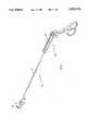
- FIG. 1shows a perspective view of a device in accordance with the present invention.
- FIG. 2is a partially sectional side view of the distal section of FIG. 1, shown in greater detail.
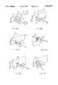
- FIGS. 3A to 3Fare views of the device of FIG. 1 placing a suture.
- FIG. 4is a perspective view of the device of FIG. 1 placing a suture in a curved surface.
- FIG. 5is a perspective view of a spiral stitch suture placed by the device of FIG. 1.
- FIG. 6is a perspective view of a needle guide of FIG. 1 with portions cut away.
- FIG. 6Ais a perspective view of a portion of the needle guide of FIG. 6.
- FIG. 6Bis an end view of the needle guide of FIG. 6.
- FIGS. 6C, 6D, and 6Eshow a portion of the needle guide of FIG. 6 as a needle passes through the needle guide.
- FIG. 7shows an alternative embodiment of the one way slot of FIG. 6.
- FIG. 8shows one embodiment of the handle at the proximal end of the device of FIG. 1.
- FIG. 9shown an alternate embodiment of the needle guides of FIG. 1.
- FIG. 10shows a side elevation sectional view of FIG. 1, including a handle mechanism.
- FIG. 11shows a cross-section view of FIG. 10 taken along the line 11--11.
- FIG. 12shows a cross-section of FIG. 10 taken along the line 12--12.
- FIG. 13is a sectional view of the proximal portion of the rod and tube depicted in FIG. 2.
- the present invention 10includes an elongated tube 20 having a proximal end and a distal end.
- a rod 30is placed through the inside the tube 20 and extends beyond each end on the tube 20. Longitudinal, radial, and tangential directions are defined with reference to the common axis of the rod 30 and tube 20.
- a first needle guide 40is attached to the distal end of the tube 20 and a second needle guide 50 is attached to the distal section of the rod 30 that extends distal to the tube 20.
- the distal end of the tube 20fits into a hole 41 in the first needle guide 40, and a tensioning device such as a screw 42 (see FIG. 6) in the first needle guide 40 allows the, first needle guide 40 to be securely attached to the tube 20.
- the first needle guide 40is "L" shaped, so that the hole 41 penetrates the short leg 43 of the needle guide 40 near the portion of the short leg 43 opposite the portion that joins the long leg 44 of the needle guide 40, and the hole 41 axis is parallel to the axis of the long leg 44 of the needle guide 40 (see FIG. 6).
- the long leg 44 of the needle guide 40is thus radially disposed away from the rod 30, and is parallel thereto. The distal end of the long leg 44 extends distal to the tube 20 and the rod 30.
- the long leg 44 of the needle guide 40is tangentially punctured by a one way needle slot 45 in the portion of the leg 44 that extends distal to the rod 30 and tube 20.
- the one way needle slot 45allows a needle 70 to pass through the slot 45 in only one direction. Attempting to move the needle 70 through the one way slot 45 in the opposite direction will cause the needle 70 to bind in the one way slot 45.
- the structure of the slot 45 that causes its one way operationis described below.
- a second needle guide 50is attached to the distal end of the rod 30 that extends beyond the distal end of the tube 20.
- the second needle guide 50is substantially similar to the first needle guide 40. It has the same L shape, but the long leg 54 of the L is somewhat shorter so that the distal end of the long leg 54 extends to the same longitudinal position as does the first needle guide 40.
- a one way slot 55is located in the second needle guide 50 in a corresponding position as the first needle slot 45 is located in the first needle guide 40, so that the needle slots 45, 55 are the same longitudinal distance beyond the distal end of the rod 30 and the same radial distance away from the axis of the rod 30.
- the one way directional action 45, 55 of the slots 45, 55is the same for both slots.
- the rod 30 and the tube 20may be rotated with respect to each other. This rotating may be accomplished by the user of the device 10 by manipulating a handle 100 attached to the proximal ends of the rod 30 and the tube 20. The structure of the handle 100 is described below. Since the tube 20 and rod 30 are rigid, the distal end of the device 10 may be positioned longitudinally or radially by the manipulating proximal end of the device 10.
- a needle 70is first placed in one of the needle guides 40, 50.
- the needle 70is preferably curved and has a sharp end 71 and an opposite end to which suture material 76 is attached.
- the needle 70is first positioned in the needle slot 45 in the first needle guide 40, so that the both ends of the needle 70 extend beyond the slot 45 (see FIG. 3A).
- the needle 70may be placed through the slot 45 before the device 10 is inserted into the body of the patient.
- the second needle guide 50is initially positioned away from the first needle guide 40 so that a space exists between the two guides 40, 50.
- the device 10is positioned so that body tissue 90 to be sutured is in the space between the needle guides 40, 50.
- the first needle guide 40is rotated so that it approaches the second needle guide 50. Since the sharp point 71 of the needle 70 extends beyond the needle guide 40, the sharp point 71 reaches the second needle guide 50 before the first needle guide 40 reaches the tissue 90. Because the needle slots 45, 55 are aligned, continued rotating of the needle guide 40 causes the needle 70 to pass from the slot 45 in the first needle guide 40 into the slot 55 in the second needle guide 50 (see FIG. 3B). When the needle 70 has been pushed through the slot 55 in the second needle guide 50 so that the needle 70 fully extends through the slot 55, the rotation of the first needle guide 40 is halted.
- the second needle guide 50is then rotated, continuing in the same tangential direction as the first needle guide 40 was initially rotated (see FIGS. 3B, 3C).
- the one way slots of the two guides 40, 50are aligned in the same tangential direction, allowing the needle 70 to pass through the second needle guide 50 slot.
- the second needle guide slot 55grips the needle 70 so that rotation of the second needle guide 50 pulls the needle 70 along with the guide 50. This occurs because if the second needle guide 50 were to move over the needle 70 without gripping the needle 70, the relative motion between the needle 70 and the needle guide 50 would be opposite the direction of motion when the needle 70 is first passed through the second needle guide 50.
- the one way slot designprevents this motion.
- the two needle guides 40, 50allow the needle 70 to be passed through tissue 90 to be sutured without either of the needle guides 40, 50 crossing that tissue 90.
- the needle 70can then be passed back from the second needle guide 50 to the first needle guide 40, again through the surface of the tissue 90 to be sutured.
- the second needle guide 50is further rotated in the same tangential direction, and the first needle guide 40 is rotated in the reverse tangential direction (see FIGS. 3D, 3E).
- the needle 70is rotated far enough so that the sharp point 71 of the needle 70 passes through the slot 45 in the first needle guide 40, in the direction of the one way slot 45 that allows for the passage of the needle 70.
- the rotation of the second needle guide 50may be halted, and the first needle 40 may then be rotated in its original direction. Rotation in this direction will cause the first needle guide slot 45 to grip the needle 70, thus the needle 70 will be transferred back to the first needle guide 40.
- the rotation of the first needle guide 40may be continued, and the second needle guide 50 may rotated in the reverse direction, so that the needle guides 40, 50 assume the position they were in before the needle 70 was passed from the first needle guide 40 to the second needle guide 50 (see FIG. 3F).
- the suture material 76 attached to the end of the needle 70is pulled along with the needle 70, so that a loop in the suture material 76 is formed as the needle 70 travels around circumference of the device 10.
- the end of the suture material 76 opposite the needle 70is terminated by a knot or a bead 78 to prevent the free end of the suture material 76 from being pulled through the tissue 90.
- FIGS. 3A-3Fshow the device 10 passing the needle 70 through an essentially planar surface 90.
- the device 10may also be used for suturing a curved surface 92, as shown in FIG. 4.
- the operation of the device 10is then essentially the same as for suturing flat surfaces: the needle 70 is passed back and forth between the needle guides 40, 50 so that the needle 70 crosses the surface 92 to be sutured, but the guides 40, 50 do not.
- the needle guide on the concave side of the tissue 92will not be rotated as much as the needle guide on the convex side of the tissue 92, since a greater portion of the circumference of the needle 70 path is on the convex side of the tissue 92.
- the rod 30may be completely rotated around the tube 20, the functioning of the device 10 is not impaired.
- the receiving needle guideassume it is needle guide 50, may be placed adjacent to the tissue 90, so that the tissue 90 is not displaced by the needle 70 movement.
- the other needle guide 40may be repositioned so that it is adjacent to the opposite surface of the tissue 90.
- the device 10may be used for suturing without the need for any supplemental devices, such as graspers. Also, the tissue 90 to be sutured will not be unnecessarily torn, as may occur if the tissue 90 is not stabilized at the time that it is punctured by the needle 70.
- the device 10may be moved longitudinally to place a series of stitches, such as a spiral stitch (see FIG. 5). After the needle 70 has been passed from one guide 40, 50 to the other, the user of the device 10 may push (or pull) on the proximal end of the device 10 to move the device 10 to a new position before the needle 70 is again passed between the guides 40, 50. After a sufficient number of passes are completed, the device 10 may be withdrawn from the body of the patient and the suture material 76 may be cut, knotted and tensioned using means known in the art. The device 10 may be used to form other stitch patterns, such as a mattress suture or a purse string suture, by appropriately positioning the needle guides 40, 50 before transferring the needle 70 between the guides 40, 50.
- a series of stitchessuch as a spiral stitch (see FIG. 5).
- the length of a suture that can be made by the device 10is limited by the distance that the needle slots 45, 55 extend beyond the proximal edge of the short leg 43 of needle guide 40. This is because it is only possible to position the needle guides 40, 50 on opposite sides of the tissue 90 to be sutured when the short leg 43 is proximal to the distal edge of the tissue 90 to be sutured. Otherwise, the needle guide holes 41, 51 that serve as the pivot points the needle guides 40, 50 would have to both be on the same side of the tissue 90, preventing the rotation of the needle guides 40, 50 more than 180°, which would not allow the needle 70 to be passed between the needle guides 40, 50. However, this is not a real impediment to the utility of the device 10, since the needle guides 40, 50 may be manufactured to any desired length.
- the needle guide 40includes three constituent pieces: a first section 140, a second section 150, and an end cap 160.
- the first section 140 and second section 150are both bisected sections of the L, taken along the axis of the long leg 44. When the first section 140 and the second section 150 abut against each other, the short leg 43 of the needle guide 40 is completely formed.
- the long leg 44is formed up to the portion of the long leg 44 that contains the slot 45. Indentations are formed in the distal edge of the first section 140 and second section 150; these indentations form part of the side wall of the slot 45.
- the indentation in section 140has a chamfer 46 to direct the needle 70 into the slot 45.
- the end cap 160is placed against the distal edge of the first section 140 and the second section 150.
- An indentation in the end cap 160forms the remainder of the side wall of the slot 45.
- the end cap 160forms the distal end of long leg 44.
- a shim 142is placed between the first section 140 and the second section 150.
- the shim 142is a flat piece of resilient material, such as metal.
- a receiving notch 152 in the second section 150receives the shim 142 (see FIG. 6A).
- the receiving notch 152contains a flat portion 154 and a sloped portion 156.
- the flat portion 154is recessed into the second section 150 to a depth approximately equal to that of the thickness of the shim 142.
- the sloped portion 156is distal to the flat portion 154, and the depth gradually increases to a depth somewhat greater than the shim 142 thickness at the distal edge of the second section 150.
- the receiving notch 152is positioned in the second section 150 so that a portion of the shim 142 extends into the slot 45 when the shim 142 is placed within the receiving notch 152.
- the surface of the first section 140 that abuts the second section 150is essentially flat.
- the shim 142will also abut the first section 140 since the receiving slot flat section 154 is only the depth of the shim 142 thickness. As best illustrated in FIG. 6B, space is present between the sloping section 156 of the receiving notch 152 and the shim 142.
- the end cap 160contains a notch 162 that aligns with the receiving notch 152.
- the shimwill fit into a portion of the notch 162 that is closer to the first section 140 than to the second section 150 (see FIG. 6C).
- the needle 70When the needle 70 is passed through the slot 45, the needle 70 will contact the shim 142, since the shim extends into the slot 45. Assume that the needle is passed from the first section 140 to the second section 150. Continued movement of the needle 70 will deflect the resilient shim 12 (see FIG. 6D). Eventually, a section of the shim 142 in the second section 150 will deflect into the sloped section 156 of the slot 152, and a corresponding section of the shim 142 in the end cap 160 will deflect from the side of the notch 162 closest to the first section 140 to the side of the notch 162 closest to the second section 150 (see FIG. 6E).
- the motion of the needle 70cannot be reversed. If the needle 70 motion were reversed, the shim 142 would revert to its unflexed position, i.e., adjacent to the first section 140. To do so, the shim 142 edge that extends into the slot 45 would have to travel in an arc from its position in the sloped portion 156 of the receiving notch 152 back to its initial position, in contact with the needle guide section 140. However, the needle 70 forms a close tolerance with the slot 45, so there is no room to allow shim 142 to travel in such an arc.
- the forward motion of the needle 70i.e., from the first needle section 140 to the second needle section 150, is unhindered, because the shim 142 is sufficiently flexed by its motion from its initial position to the sloped portion 156 of the receiving notch 152 that its edge does not sufficiently protrude into the slot 45 to impede the motion of the needle 70.
- the needle 70can move in its initial direction because the needle 70 has already deflected the shim 142 out of the direct path of the needle 70.
- the needle 70cannot reverse direction because that would require that the shim 142 bend in the opposite direction, and the tolerances of the needle 70, slot 45, and shim 142 are such that there is insufficient space for that to occur.
- the slot 45will pull the needle 70 along instead of allowing the guide 40 to slide over the needle 70. If the guide 40 were to slide over the needle 70, the relative motion between the guide 40 and the needle 70 would be the same as if the guide 40 were held stationary and the needle 70 were attempted to be moved from the second section 140 to the first section 150.
- the passing of the needle 70 from one guide 40, 50 to the otheris an extension of passing the needle 70 through one guide.
- the needle 70deforms a second shim (not shown) in the second needle guide 50, in exactly the same way as the first shim was deformed, as described above (see FIG. 6C).
- the second guide 50will pull the needle 70 along to prevent the needle 70 from moving through the second needle slot 55 in the reverse direction (see FIGS. 3B, 3C).
- the first needle guide 40is held stationary at this time, and the needle 70 travels through the first needle guide 40 from the first section 140 to the second section 150.
- the attachment between the first section 140 of the needle guide 40 and the second section 150 of the needle guidemay be perfected by a variety of methods.
- a preferred methodis simply to form the attachment with the screw 42 that tensions the guide 40 onto the tube.
- the end cap 160is preferably attached to the remainder of the needle guide 40 (either section 140 or 150) by a fastener such as a screw (not shown), although other methods, such as the use of adhesives, may also produce good results.
- the needle 70'may have teeth 71' formed in its periphery which may slide through pawls 46' formed in the needle slot 45' in one direction, but would bind if the needle 70' were attempted to be slid in the opposite direction (see FIG. 7).
- the device 10preferably includes a handle 100 that enables the rod 30 and the tube 20 to be relatively rotated.
- the handle 100includes two lever arms 110, 120, both lever arms being terminated at one of their ends in a loop 111, 121 respectively, so that the handle 100 may be easily grasped by the operator of the device 10 by inserting a finger through each loop 111, 121.
- the lever arms 110, 120are pivotally connected to each other at pivot point 113.
- Lever arm 110is connected to a hollow screw 114, preferably having four independent threads 116.
- the screw 114is aligned with the axis of the rod 30, and the proximal end of the screw 114 is attached to the rod 30, in a manner described below.
- Separating lever arm 110 from lever arm 120longitudinally retracts the screw 114.
- the screwis at least partially encased by a handle body 118.
- Four pins 122are spaced around the interior of the body 118, so that one pin fits within each of the four threads 116 (see FIG. 12).
- the longitudinal motion of the screw 114causes the screw 114 to rotates the threads 116 mesh with the pins 122.
- the screw 114may slide with the rod 30 longitudinally, but is rotationally fixed to the rod 30. This is preferably accomplished by two radial wings 32 rod that extend from the distal portion of the rod 30 that fit into two slots 124 formed into the interior portion of the screw 114.
- the rod 30may move longitudinally in the screw 114, because the wings 32 may move longitudinally within the slots 124. However, rotation of the screw 114 will cause rotation of the rod 30, as the slots 124 grip the wings 32.
- the rod 30is longitudinally connected to the tube 20, although the rod 30 and tube 20 may rotate with respect to each other. This may be accomplished by an annular ridge 34 on the rod 30 that fits into a groove 24 on the tube 20 (see FIG. 13).
- each lever arm 110, 120may be controlled by a finger (or thumb) of the surgeon, the device 10 may be operated with only one hand.
- the tube 20is rigidly connected to the handle body 118, so that the tube 20 may be rotated by rotating the handle body 118.
- An alternate embodimentdispenses with the handle 100 (see FIG. 8). Instead, an arm 110' is firmly attached to the tube 20 and another arm 120' is firmly attached to the rod 30, with both arm 110', 120' axes transverse to the rod 30 and tube 20 axes. The surgeon may then rotate the arms 110', 120' to rotate the needle guides 40, 50. While this alternate embodiment is simpler and less expensive to manufacture than the preferred embodiment, it is not easily operated with one hand.
- the device 10may be inserted through an introducing tube (not pictured) to reach the operation site of a patient, as occurs in laparascopic surgery.
- the handle 100would remain proximal to the introducing tube, so that it may be manipulated by the surgeon.
- the device 10may be dimensioned to fit through an introducing tube of a desired diameter, depending upon the specific suturing needs of differing operations.
- the needle guides 40, 50 as above describedcontain three parts, and the shim 142. However, some of these parts could be combined together, although that may complicate the manufacturing process.
- the needle guides 40, 50have been described as L shaped. The L shape effectively allows one section of a guide 40, 50 to be attached to the tube 20 or rod 30, and another section of the guide 40, 50 (containing the guide slots 45, 55) to project longitudinally and radially beyond the distal end of the tube 20 and rod 30.
- needle guides 40", 50"could be straight arms that attach to the rod or the tube and extend distal and radially away from the distal end of the rod (see FIG. 9).
Landscapes
- Health & Medical Sciences (AREA)
- Life Sciences & Earth Sciences (AREA)
- Surgery (AREA)
- Heart & Thoracic Surgery (AREA)
- Engineering & Computer Science (AREA)
- Biomedical Technology (AREA)
- Nuclear Medicine, Radiotherapy & Molecular Imaging (AREA)
- Medical Informatics (AREA)
- Molecular Biology (AREA)
- Animal Behavior & Ethology (AREA)
- General Health & Medical Sciences (AREA)
- Public Health (AREA)
- Veterinary Medicine (AREA)
- Surgical Instruments (AREA)
Abstract
Description
The present invention relates to the broad field of suturing, and more specifically to a device useful for intracorporeal suturing as occurs in laparoscopic surgery.
Sutures are used in numerous medical procedures such as closing ruptured tissue or grafting tissue together. Traditionally, sutures have been placed by hand, with a surgeon repeatedly passing a thread-bearing needle through the tissue to be sutured. Although this is a tedious and time consuming task, satisfactory results may generally be obtained. However, the traditional suturing method cannot be used with surgical techniques that allow surgery to be performed inside of a patient's body by accessing the surgical site through an introducing tube or tubes, such as trocars and cannulae.
In these surgical techniques, the surgeon does not have direct visual or tactile access to the operation site; instead, the site is viewed through a laparoscope or endoscope or similar device, and the surgery is performed through specialized instruments inserted through the introducing tubes. In the following discussion, the term laparoscopy is meant to encompass any form of invasive surgery that is performed inside the body of a patient via introducing tubes, since the distinctions between the various types of invasive surgery are not germane to the present invention.
Laparoscopic surgery is often preferable to traditional open surgery because it is less invasive than traditional open surgery--the smaller wound created during the surgical procedure allows for a much more rapid recovery by the patient. The patient may thus have a shorter hospital stay or, in some cases, no hospital stay whatsoever.
Traditional manual surgical techniques cannot be used in laparoscopic surgery, since a surgeon cannot place his hands at the operation site. Still, it is necessary or desirable to place sutures in many different laparoscopic procedures. For example, in laparoscopic cholecystectomy, the cystic duct or artery can be ligated using suturing and knot tying techniques rather than the alternative technique of an automatic clip. Although laparoscopic staplers have been developed, laparoscopic sutures will still be needed for many purposes such as closing defects in a staple line, placing purse-string sutures for end-to-end stapling, closing mesenteric defects, and ligating large blood vessels.
Several devices and techniques have been developed to fit through the narrow tubes used in laparoscopic suturing. The most basic devices are simple needle holders that use plier-like opposable jaws to grasp and manipulate a suturing needle. However, the small, curved needles used in laparoscopic surgery are difficult to grasp, and may easily slip from a needle holder, causing unnecessary tissue damage to the patient, and a consequently longer recovery period. Also, it is a slow and difficult process to manipulate the suturing needle through an introducing tube, which allows for a prolonged time for a surgeon to make an error, such as inadvertently allowing the needle to slip from the needle holder. Attempts have been made to improve upon the plier-like needle drivers, such as in U.S. Pat. No. 5,376,096 issued Dec. 27, 1994 to Foster. However, as with plier-like needle drivers, the Foster device does not firmly connect the needle driver to the needle, so that the needle may still be misdirected or even lost in the body of the patient.
More sophisticated suturing devices have been developed for laparoscopic type surgery. For instance, U.S. Pat. No. 5,364,408 issued Nov. 15, 1994 to Gordon discloses a device where two needles extend from opposite sides of the device, and may be pushed through surrounding tissue and then be recaptured by the device. While this device may be useful for making a single loop suture, its inability to make sutures of more than one loop limits its versatility. U.S. Pat. No. 5,403,328 issued Apr. 4, 1995 to Shallman discloses a device with a needle pivotally attached to an elongate tube that may be inserted into the body of a patient. A suture may be placed by pivoting the needle away from the device and retracting the device. However, the device makes no provision for retracing the needle adjacent to its initial pass, hence it is only useful to place one stitch and may not be used to place a series of stitches, which is commonly required in laparascopic suturing. A similar device is disclosed in U.S. Pat. No. 5,397,325 issued Mar. 14, 1995 to Della Badia et al. U.S. Pat. No. 5,437,681 issued Aug. 1, 1995 to Meade et al. discloses a device that allows for a series of stitches to be placed in the body of a patient. That device is quite complicated, containing numerous springs, gears, cams, and pinions with their attendant manufacturing costs and the possibility of malfunction. Also, the Meade et al. device is positioned on only one side of the tissue to be sutured, which allows the tissue to be displaced by the penetrating action of the needle. Thus, there exists a need for a simple suturing device which may be used to place a suture of any desired length into a patient's body during a laparscopic or similar operation.
The present invention is a method and apparatus for suturing, with particular application to laparascopic surgery or similar surgical methods where surgical instruments are placed into the body of patient through introducing tubes. The suture may be a standard spiral stitch or may have a different stitch pattern if desired.
A device embodying the present invention includes a rod and a concentric tube placed around a segment of the rod. The rod and tube may be rotated in relation to each other in either direction. The rod may be rotated by manipulating a handle located at the proximal end of the device. The handle resembles that of scissors, in that it consists of two finger-ring equipped lever arms, that are hinged together. One lever arm is attached to a screw, and the other end of the screw is attached to the rod. Moving the lever arms pushes or pulls the screw. A handle body contains protrusions that mesh with the screw thread, so that the screw rotates as it is pushed or pulled. The rod is coupled to the screw with a tongue and groove connection that allows longitudinal motion therebetween, but causes the rod and screw to rotate together. The tube is attached to the handle body, so the rotation of the screw causes the rod to rotate relative to the tube.
The distal end of the device includes a first needle guide attached to the tube and a second needle guide attached to the rod. The needle guides extend radially out from the rod and tube and project distal to the rod and tube. Rotating the rod and tube in relation to each other rotates the needle guides, whose rotational path defines a circumference around the axis of rod and tube. Each needle guide contains a one way needle slot, that allows the needle to move through the slot when the needle travels through the slot in one direction. However, the needle binds in the slot when force is applied urging the needle in the opposite direction.
A suturing needle with a pointed end and suturing thread attached to the opposite end is placed through one of the guides (assume the first guide for the following description) before the device is introduced into the body of patient. The device is then positioned so that the two guides are on opposite sides of a tissue surface that is to be sutured. The second guide is positioned against the tissue. The first guide is then rotated so that the needle passes through the tissue and into the slot of the second guide. The second guide may then be rotated, and the one way directional slots causes the needle to bind in the second slot and to move along with the second guide. Thus, the needle is passed through the tissue surface to be sutured. The first needle guide may be rotated in the opposite direction from its initial rotation, until it abuts the tissue. The first needle guide will then abut the tissue on the opposite end of the circumferential arc defined by the rotational path of the first needle guide, compared to the point at which the needle was passed from the first needle guide to the second. The second needle guide may be further rotated so that the needle is passed through the tissue again, back to the first needle guide. The process can be repeated a number of times to achieve a desired suture length. Along with passing the needle through the tissue between the needle guides, the device may also be moved longitudinally or radially to form, for example, a spiral suture or a mattress suture.
To perform laparascopic suturing, the distal end of the device is inserted into an introducing tube, which extends from outside of the patient's body to the operation site within the patient's body. The handle of the device is left outside of the tube and outside of the patient's body, so that a surgeon may manipulate the handle and thus the needle guides. Once the suture is placed, the suture material may be severed and knotted by any of the means known in the art. Finally, the suturing device is withdrawn from the introducing tube.
The one way needle slot action may be achieved by several methods. In a preferred embodiment, a resilient shim protrudes into the needle slot. The needle may be pushed through the slot, and will deflect the shim into a receiving groove in the needle guide. As the needle motion is continued and a portion of the needle passes the shim, the needle motion cannot be reversed, because the needle blocks the path the shim would have to take to assume its initial position.
The present invention may be dimensioned to be inserted through introducing tubes of various sizes, allowing for its use in laparoscopic surgery. Because the invention positively grips the suturing needle and supports the surrounding tissue, it may be used without the assistance of any other device, such as clamps, and eliminates the possibility of losing the needle within a patient's body. Also, tissue damage resulting from passing a needle through unsupported tissue is reduced.
The device may be operated with one hand, allowing the surgeon to use his other hand to perform other tasks. The present invention achieves the above advantages even though it comprises substantially fewer components and is of a simpler design than prior art suturing devices.
FIG. 1 shows a perspective view of a device in accordance with the present invention.
FIG. 2 is a partially sectional side view of the distal section of FIG. 1, shown in greater detail.
FIGS. 3A to 3F are views of the device of FIG. 1 placing a suture.
FIG. 4 is a perspective view of the device of FIG. 1 placing a suture in a curved surface.
FIG. 5 is a perspective view of a spiral stitch suture placed by the device of FIG. 1.
FIG. 6 is a perspective view of a needle guide of FIG. 1 with portions cut away.
FIG. 6A is a perspective view of a portion of the needle guide of FIG. 6.
FIG. 6B is an end view of the needle guide of FIG. 6.
FIGS. 6C, 6D, and 6E show a portion of the needle guide of FIG. 6 as a needle passes through the needle guide.
FIG. 7 shows an alternative embodiment of the one way slot of FIG. 6.
FIG. 8 shows one embodiment of the handle at the proximal end of the device of FIG. 1.
FIG. 9 shown an alternate embodiment of the needle guides of FIG. 1.
FIG. 10 shows a side elevation sectional view of FIG. 1, including a handle mechanism.
FIG. 11 shows a cross-section view of FIG. 10 taken along the line 11--11.
FIG. 12 shows a cross-section of FIG. 10 taken along theline 12--12.
FIG. 13 is a sectional view of the proximal portion of the rod and tube depicted in FIG. 2.
With reference to FIG. 2, thepresent invention 10 includes anelongated tube 20 having a proximal end and a distal end. Arod 30 is placed through the inside thetube 20 and extends beyond each end on thetube 20. Longitudinal, radial, and tangential directions are defined with reference to the common axis of therod 30 andtube 20. Afirst needle guide 40 is attached to the distal end of thetube 20 and asecond needle guide 50 is attached to the distal section of therod 30 that extends distal to thetube 20. The distal end of thetube 20 fits into a hole 41 in thefirst needle guide 40, and a tensioning device such as a screw 42 (see FIG. 6) in thefirst needle guide 40 allows the,first needle guide 40 to be securely attached to thetube 20.
Thefirst needle guide 40 is "L" shaped, so that the hole 41 penetrates theshort leg 43 of theneedle guide 40 near the portion of theshort leg 43 opposite the portion that joins thelong leg 44 of theneedle guide 40, and the hole 41 axis is parallel to the axis of thelong leg 44 of the needle guide 40 (see FIG. 6). Thelong leg 44 of theneedle guide 40 is thus radially disposed away from therod 30, and is parallel thereto. The distal end of thelong leg 44 extends distal to thetube 20 and therod 30.
Thelong leg 44 of theneedle guide 40 is tangentially punctured by a oneway needle slot 45 in the portion of theleg 44 that extends distal to therod 30 andtube 20. The oneway needle slot 45 allows aneedle 70 to pass through theslot 45 in only one direction. Attempting to move theneedle 70 through the oneway slot 45 in the opposite direction will cause theneedle 70 to bind in the oneway slot 45. The structure of theslot 45 that causes its one way operation is described below.
Asecond needle guide 50 is attached to the distal end of therod 30 that extends beyond the distal end of thetube 20. Thesecond needle guide 50 is substantially similar to thefirst needle guide 40. It has the same L shape, but thelong leg 54 of the L is somewhat shorter so that the distal end of thelong leg 54 extends to the same longitudinal position as does thefirst needle guide 40. A oneway slot 55 is located in thesecond needle guide 50 in a corresponding position as thefirst needle slot 45 is located in thefirst needle guide 40, so that theneedle slots rod 30 and the same radial distance away from the axis of therod 30. The one waydirectional action slots
Therod 30 and thetube 20 may be rotated with respect to each other. This rotating may be accomplished by the user of thedevice 10 by manipulating ahandle 100 attached to the proximal ends of therod 30 and thetube 20. The structure of thehandle 100 is described below. Since thetube 20 androd 30 are rigid, the distal end of thedevice 10 may be positioned longitudinally or radially by the manipulating proximal end of thedevice 10.
To use thedevice 10 to place a suture, aneedle 70 is first placed in one of the needle guides 40, 50. Theneedle 70 is preferably curved and has a sharp end 71 and an opposite end to whichsuture material 76 is attached. In the following description of the operation of thedevice 10 to place a suture, assume that theneedle 70 is first positioned in theneedle slot 45 in thefirst needle guide 40, so that the both ends of theneedle 70 extend beyond the slot 45 (see FIG. 3A). Theneedle 70 may be placed through theslot 45 before thedevice 10 is inserted into the body of the patient.
Thesecond needle guide 50 is initially positioned away from thefirst needle guide 40 so that a space exists between the twoguides device 10 is positioned so thatbody tissue 90 to be sutured is in the space between the needle guides 40, 50. Thefirst needle guide 40 is rotated so that it approaches thesecond needle guide 50. Since the sharp point 71 of theneedle 70 extends beyond theneedle guide 40, the sharp point 71 reaches thesecond needle guide 50 before thefirst needle guide 40 reaches thetissue 90. Because theneedle slots needle guide 40 causes theneedle 70 to pass from theslot 45 in thefirst needle guide 40 into theslot 55 in the second needle guide 50 (see FIG. 3B). When theneedle 70 has been pushed through theslot 55 in thesecond needle guide 50 so that theneedle 70 fully extends through theslot 55, the rotation of thefirst needle guide 40 is halted.
Thesecond needle guide 50 is then rotated, continuing in the same tangential direction as thefirst needle guide 40 was initially rotated (see FIGS. 3B, 3C). The one way slots of the twoguides needle 70 to pass through thesecond needle guide 50 slot. When thesecond needle guide 50 is rotated, the secondneedle guide slot 55 grips theneedle 70 so that rotation of thesecond needle guide 50 pulls theneedle 70 along with theguide 50. This occurs because if thesecond needle guide 50 were to move over theneedle 70 without gripping theneedle 70, the relative motion between theneedle 70 and theneedle guide 50 would be opposite the direction of motion when theneedle 70 is first passed through thesecond needle guide 50. The one way slot design prevents this motion.
It can thus be appreciated that the two needle guides 40, 50 allow theneedle 70 to be passed throughtissue 90 to be sutured without either of the needle guides 40, 50 crossing thattissue 90. Theneedle 70 can then be passed back from thesecond needle guide 50 to thefirst needle guide 40, again through the surface of thetissue 90 to be sutured. Thesecond needle guide 50 is further rotated in the same tangential direction, and thefirst needle guide 40 is rotated in the reverse tangential direction (see FIGS. 3D, 3E). Eventually, theneedle 70 is rotated far enough so that the sharp point 71 of theneedle 70 passes through theslot 45 in thefirst needle guide 40, in the direction of the oneway slot 45 that allows for the passage of theneedle 70. The rotation of thesecond needle guide 50 may be halted, and thefirst needle 40 may then be rotated in its original direction. Rotation in this direction will cause the firstneedle guide slot 45 to grip theneedle 70, thus theneedle 70 will be transferred back to thefirst needle guide 40. The rotation of thefirst needle guide 40 may be continued, and thesecond needle guide 50 may rotated in the reverse direction, so that the needle guides 40, 50 assume the position they were in before theneedle 70 was passed from thefirst needle guide 40 to the second needle guide 50 (see FIG. 3F).
As shown in FIGS. 3A-3F, thesuture material 76 attached to the end of theneedle 70 is pulled along with theneedle 70, so that a loop in thesuture material 76 is formed as theneedle 70 travels around circumference of thedevice 10. Preferably, the end of thesuture material 76 opposite theneedle 70 is terminated by a knot or abead 78 to prevent the free end of thesuture material 76 from being pulled through thetissue 90.
FIGS. 3A-3F show thedevice 10 passing theneedle 70 through an essentiallyplanar surface 90. Thedevice 10 may also be used for suturing acurved surface 92, as shown in FIG. 4. The operation of thedevice 10 is then essentially the same as for suturing flat surfaces: theneedle 70 is passed back and forth between the needle guides 40, 50 so that theneedle 70 crosses thesurface 92 to be sutured, but theguides tissue 92 will not be rotated as much as the needle guide on the convex side of thetissue 92, since a greater portion of the circumference of theneedle 70 path is on the convex side of thetissue 92. However, since therod 30 may be completely rotated around thetube 20, the functioning of thedevice 10 is not impaired.
The use of the two needle guides 40, 50, one located on each surface of the tissue 90 (or 92), stabilizes the tissue when theneedle 70 is passed through thetissue 90. The receiving needle guide, assume it isneedle guide 50, may be placed adjacent to thetissue 90, so that thetissue 90 is not displaced by theneedle 70 movement. When theneedle 70 is passed through thetissue 90 and into theneedle guide 50 so that theneedle guide 50 may be rotated, along with theneedle 70, away from thetissue 90, theother needle guide 40 may be repositioned so that it is adjacent to the opposite surface of thetissue 90. When theneedle 70 is next passed between the needle guides 40, 50, thetissue 90 will again be stabilized. It can thus be appreciated that thedevice 10 may be used for suturing without the need for any supplemental devices, such as graspers. Also, thetissue 90 to be sutured will not be unnecessarily torn, as may occur if thetissue 90 is not stabilized at the time that it is punctured by theneedle 70.
Thedevice 10 may be moved longitudinally to place a series of stitches, such as a spiral stitch (see FIG. 5). After theneedle 70 has been passed from oneguide device 10 may push (or pull) on the proximal end of thedevice 10 to move thedevice 10 to a new position before theneedle 70 is again passed between theguides device 10 may be withdrawn from the body of the patient and thesuture material 76 may be cut, knotted and tensioned using means known in the art. Thedevice 10 may be used to form other stitch patterns, such as a mattress suture or a purse string suture, by appropriately positioning the needle guides 40, 50 before transferring theneedle 70 between theguides
The length of a suture that can be made by thedevice 10 is limited by the distance that theneedle slots short leg 43 ofneedle guide 40. This is because it is only possible to position the needle guides 40, 50 on opposite sides of thetissue 90 to be sutured when theshort leg 43 is proximal to the distal edge of thetissue 90 to be sutured. Otherwise, the needle guide holes 41, 51 that serve as the pivot points the needle guides 40, 50 would have to both be on the same side of thetissue 90, preventing the rotation of the needle guides 40, 50 more than 180°, which Would not allow theneedle 70 to be passed between the needle guides 40, 50. However, this is not a real impediment to the utility of thedevice 10, since the needle guides 40, 50 may be manufactured to any desired length.
With reference to FIG. 6, the operation of the oneway slot 45 is now explained, it being understood that the oneway slot 55 operates in the same manner. Theneedle guide 40 includes three constituent pieces: afirst section 140, asecond section 150, and anend cap 160. Thefirst section 140 andsecond section 150 are both bisected sections of the L, taken along the axis of thelong leg 44. When thefirst section 140 and thesecond section 150 abut against each other, theshort leg 43 of theneedle guide 40 is completely formed. Thelong leg 44 is formed up to the portion of thelong leg 44 that contains theslot 45. Indentations are formed in the distal edge of thefirst section 140 andsecond section 150; these indentations form part of the side wall of theslot 45. The indentation insection 140 has achamfer 46 to direct theneedle 70 into theslot 45. Theend cap 160 is placed against the distal edge of thefirst section 140 and thesecond section 150. An indentation in theend cap 160 forms the remainder of the side wall of theslot 45. Theend cap 160 forms the distal end oflong leg 44.
Ashim 142 is placed between thefirst section 140 and thesecond section 150. Theshim 142 is a flat piece of resilient material, such as metal. A receivingnotch 152 in thesecond section 150 receives the shim 142 (see FIG. 6A). The receivingnotch 152 contains aflat portion 154 and asloped portion 156. Theflat portion 154 is recessed into thesecond section 150 to a depth approximately equal to that of the thickness of theshim 142. The slopedportion 156 is distal to theflat portion 154, and the depth gradually increases to a depth somewhat greater than theshim 142 thickness at the distal edge of thesecond section 150. The receivingnotch 152 is positioned in thesecond section 150 so that a portion of theshim 142 extends into theslot 45 when theshim 142 is placed within the receivingnotch 152.
The surface of thefirst section 140 that abuts thesecond section 150 is essentially flat. When thefirst section 140 is connected to thesecond section 150, theshim 142 will also abut thefirst section 140 since the receiving slotflat section 154 is only the depth of theshim 142 thickness. As best illustrated in FIG. 6B, space is present between thesloping section 156 of the receivingnotch 152 and theshim 142.
As seen in FIG. 6 and FIGS. 6C-6E, theend cap 160 contains anotch 162 that aligns with the receivingnotch 152. When there is no force on the shim, the shim will fit into a portion of thenotch 162 that is closer to thefirst section 140 than to the second section 150 (see FIG. 6C).
When theneedle 70 is passed through theslot 45, theneedle 70 will contact theshim 142, since the shim extends into theslot 45. Assume that the needle is passed from thefirst section 140 to thesecond section 150. Continued movement of theneedle 70 will deflect the resilient shim 12 (see FIG. 6D). Eventually, a section of theshim 142 in thesecond section 150 will deflect into the slopedsection 156 of theslot 152, and a corresponding section of theshim 142 in theend cap 160 will deflect from the side of thenotch 162 closest to thefirst section 140 to the side of thenotch 162 closest to the second section 150 (see FIG. 6E).
Once the sharp end 71 of theneedle 70 has passed theshim 142, the motion of theneedle 70 cannot be reversed. If theneedle 70 motion were reversed, theshim 142 would revert to its unflexed position, i.e., adjacent to thefirst section 140. To do so, theshim 142 edge that extends into theslot 45 would have to travel in an arc from its position in the slopedportion 156 of the receivingnotch 152 back to its initial position, in contact with theneedle guide section 140. However, theneedle 70 forms a close tolerance with theslot 45, so there is no room to allowshim 142 to travel in such an arc. Note that the forward motion of theneedle 70, i.e., from thefirst needle section 140 to thesecond needle section 150, is unhindered, because theshim 142 is sufficiently flexed by its motion from its initial position to the slopedportion 156 of the receivingnotch 152 that its edge does not sufficiently protrude into theslot 45 to impede the motion of theneedle 70. Stated another way, theneedle 70 can move in its initial direction because theneedle 70 has already deflected theshim 142 out of the direct path of theneedle 70. Theneedle 70 cannot reverse direction because that would require that theshim 142 bend in the opposite direction, and the tolerances of theneedle 70,slot 45, and shim 142 are such that there is insufficient space for that to occur.
When the forward motion of theneedle 70 is halted and theneedle guide 40 is moved forward, theslot 45 will pull theneedle 70 along instead of allowing theguide 40 to slide over theneedle 70. If theguide 40 were to slide over theneedle 70, the relative motion between theguide 40 and theneedle 70 would be the same as if theguide 40 were held stationary and theneedle 70 were attempted to be moved from thesecond section 140 to thefirst section 150.
The passing of theneedle 70 from oneguide needle 70 through one guide. As theneedle 70 is passed from thefirst guide 40 to thesecond guide 50, theneedle 70 deforms a second shim (not shown) in thesecond needle guide 50, in exactly the same way as the first shim was deformed, as described above (see FIG. 6C). When the movement of the needle is stopped and thesecond guide 50 is moved in the same direction as theneedle 70 initially was moved, thesecond guide 50 will pull theneedle 70 along to prevent theneedle 70 from moving through thesecond needle slot 55 in the reverse direction (see FIGS. 3B, 3C). Thefirst needle guide 40 is held stationary at this time, and theneedle 70 travels through thefirst needle guide 40 from thefirst section 140 to thesecond section 150.
The attachment between thefirst section 140 of theneedle guide 40 and thesecond section 150 of the needle guide may be perfected by a variety of methods. A preferred method is simply to form the attachment with thescrew 42 that tensions theguide 40 onto the tube. Similarly, theend cap 160 is preferably attached to the remainder of the needle guide 40 (eithersection 140 or 150) by a fastener such as a screw (not shown), although other methods, such as the use of adhesives, may also produce good results.
While the above described oneway slots
With reference to FIG. 10, thedevice 10 preferably includes ahandle 100 that enables therod 30 and thetube 20 to be relatively rotated. Thehandle 100 includes twolever arms handle 100 may be easily grasped by the operator of thedevice 10 by inserting a finger through each loop 111, 121. Thelever arms pivot point 113.
Thescrew 114 may slide with therod 30 longitudinally, but is rotationally fixed to therod 30. This is preferably accomplished by tworadial wings 32 rod that extend from the distal portion of therod 30 that fit into twoslots 124 formed into the interior portion of thescrew 114. Therod 30 may move longitudinally in thescrew 114, because thewings 32 may move longitudinally within theslots 124. However, rotation of thescrew 114 will cause rotation of therod 30, as theslots 124 grip thewings 32. Therod 30 is longitudinally connected to thetube 20, although therod 30 andtube 20 may rotate with respect to each other. This may be accomplished by anannular ridge 34 on therod 30 that fits into a groove 24 on the tube 20 (see FIG. 13). Note that since eachlever arm device 10 may be operated with only one hand. Thetube 20 is rigidly connected to thehandle body 118, so that thetube 20 may be rotated by rotating thehandle body 118.
An alternate embodiment dispenses with the handle 100 (see FIG. 8). Instead, an arm 110' is firmly attached to thetube 20 and another arm 120' is firmly attached to therod 30, with both arm 110', 120' axes transverse to therod 30 andtube 20 axes. The surgeon may then rotate the arms 110', 120' to rotate the needle guides 40, 50. While this alternate embodiment is simpler and less expensive to manufacture than the preferred embodiment, it is not easily operated with one hand.
Thedevice 10 may be inserted through an introducing tube (not pictured) to reach the operation site of a patient, as occurs in laparascopic surgery. Thehandle 100 would remain proximal to the introducing tube, so that it may be manipulated by the surgeon. Thedevice 10 may be dimensioned to fit through an introducing tube of a desired diameter, depending upon the specific suturing needs of differing operations.
It should be appreciated that the above described embodiment and alternate versions thereof could be modified in many ways without materially affecting the performance of the invention. For example, the needle guides 40, 50 as above described contain three parts, and theshim 142. However, some of these parts could be combined together, although that may complicate the manufacturing process. As another example, the needle guides 40, 50 have been described as L shaped. The L shape effectively allows one section of aguide tube 20 orrod 30, and another section of theguide 40, 50 (containing theguide slots 45, 55) to project longitudinally and radially beyond the distal end of thetube 20 androd 30. However, other shapes may accomplish the same purpose using the same principle. For example, needle guides 40", 50" could be straight arms that attach to the rod or the tube and extend distal and radially away from the distal end of the rod (see FIG. 9).
Claims (14)
1. A suturing apparatus for a needle having a sharp end and suture material attached to the needle opposite the sharp end, comprising:
a first needle guide and a second needle guide, each guide containing a directional slot having a first slot side and a second slot side, each guide slot having directional means for allowing the needle to pass through the slot from the first slot side to the second slot side opposite the first slot side and preventing the needle from passing through the slot from the second slot side to the first slot side;
the first and second needle guide slots being rotationally mounted in relation to one another, whereby rotating the guide slots passes the needle from the first needle guide slot to the second needle guide slot further rotating the guide slots passes the needle from the second guide to the first guide slot, the sharp end of the needle passing through each guide slot from the first slot side to the second slot side, the needle moving in a single direction.
2. The apparatus of claim 1, further comprising: a tube having a distal end and a proximal end, the first needle guide being mounted to the distal end of the tube; and
a rod having a distal end and a proximal end, the rod being located partially within the tube and being rotatable therewithin, with the distal end of the rod extending past the distal end of the tube, the second needle guide being mounted to the distal end of the rod.
3. The apparatus of claim 2, wherein the needle slots of the first needle guide and the second needle guide are located distal to the rod and radially apart from the rod axis.
4. The apparatus of claim 3, wherein the first needle guide directional mean includes a shim, the shim being made of a resilient material, with a portion of the shim extending into the first needle guide slot.
5. The apparatus of claim 4, wherein the first needle guide contains a recessed portion to contain the shim, the recessed portion being wider than the thickness of the shim at the portion of the shim that extends into the first needle guide slot, and the recessed portion being approximately the thickness of the shim at a portion of the shim that does not extend into the first needle guide slot, so that the shim is at least partially displaced by the needle as the needle moves through the first needle guide slot.
6. The apparatus of claim 5, wherein the second needle guide slot has substantially the same structure as the first needle guide slot.
7. The apparatus of claim 6, further comprising a handle, the handle being attached to the proximal ends of the tube and the rod and including means for relatively rotating the rod and tube.
8. The apparatus of claim 7, wherein the handle comprises:
a first lever arm and a second lever arm, the lever arms being pivotally connected to one another;
a threaded screw having a distal end and a proximal end, the proximal end of the screw being attached to the second lever arm, and the distal end of the screw being attached to the rod;
a handle housing, with a protrusion adapted to fit into a thread of the threaded screw; and
the handle housing at least partially contains the screw, pivoting the first and second lever arms moves the screw with respect to the handle housing in the direction of the screw axis, and the movement of the screw thread through the handle housing protrusion causes the screw to rotate with respect to the handle housing.
9. The apparatus of claim 8, wherein the rod contains a flange that extends radially away from the rod axis, and the screw contains a hollow section adapted to receive the rod section including the flange, so as to form a close tolerance therewith.
10. A method of suturing a surface comprising the steps of:
(a) placing a needle through a first needle guide, the needle having a sharp end and suture material attached to an opposite end, so that the sharp end of the needle projects ahead of the needle guide;
(b) positioning the first needle guide on one side of the surface to be sutured;
(c) positioning a second needle guide on the opposite side of the surface;
(d) forcing the needle through the surface and into the second needle guide, so that the sharp end of the needle extends through the second needle guide;
(e) repositioning the first and second needle guides;
(f) forcing the needle through the surface to be sutured so that the sharp end of the needle extends through the first needle guide;
wherein the above steps are performed such that the needle is moved in a single direction and wherein the first needle guide is attached to a tube and the second needle guide is attached to a rod fitted at least partially within the tube and is rotatable therewithin, and steps (d)-(f) are accomplished by relatively rotating the tube and the rod.
11. The method of claim 10, wherein the tube and rod can be relatively rotated by manipulating a handle operatively engaged with the tube and rod.
12. The method of claim 11, wherein the needle guides allow relative motion between the guides and the needle in only one direction, and step (e) causes the needle to be completely withdrawn from the first needle guide.
13. The method of claim 12, step (e) further comprising: repositioning the needle guides longitudinally with respect to the axis of the tube.
14. The method of claim 13, wherein step (e) is partially performed by pushing the handle longitudinally with respect to the tube axis.
Priority Applications (1)
| Application Number | Priority Date | Filing Date | Title |
|---|---|---|---|
| US08/546,581US5707379A (en) | 1995-10-20 | 1995-10-20 | Method and apparatus for intracorporeal suturing |
Applications Claiming Priority (1)
| Application Number | Priority Date | Filing Date | Title |
|---|---|---|---|
| US08/546,581US5707379A (en) | 1995-10-20 | 1995-10-20 | Method and apparatus for intracorporeal suturing |
Publications (1)
| Publication Number | Publication Date |
|---|---|
| US5707379Atrue US5707379A (en) | 1998-01-13 |
Family
ID=24181055
Family Applications (1)
| Application Number | Title | Priority Date | Filing Date |
|---|---|---|---|
| US08/546,581Expired - Fee RelatedUS5707379A (en) | 1995-10-20 | 1995-10-20 | Method and apparatus for intracorporeal suturing |
Country Status (1)
| Country | Link |
|---|---|
| US (1) | US5707379A (en) |
Cited By (115)
| Publication number | Priority date | Publication date | Assignee | Title |
|---|---|---|---|---|
| US5954733A (en)* | 1996-11-27 | 1999-09-21 | Yoon; Inbae | Suturing instrument with rotatably mounted needle driver and catcher |
| US5954731A (en)* | 1997-07-29 | 1999-09-21 | Yoon; Inbae | Surgical instrument with multiple rotatably mounted spreadable end effectors |
| US5957937A (en)* | 1996-11-27 | 1999-09-28 | Yoon; Inbae | Suturing instrument with spreadable needle holder mounted for arcuate movement |
| US5984932A (en)* | 1996-11-27 | 1999-11-16 | Yoon; Inbae | Suturing instrument with one or more spreadable needle holders mounted for arcuate movement |
| US5993466A (en)* | 1997-06-17 | 1999-11-30 | Yoon; Inbae | Suturing instrument with multiple rotatably mounted spreadable needle holders |
| US5993467A (en)* | 1996-11-27 | 1999-11-30 | Yoon; Inbae | Suturing instrument with rotatably mounted spreadable needle holder |
| US6004332A (en) | 1997-05-01 | 1999-12-21 | Yoon; Inbae | Suturing instrument with multiple rotatably mounted offset needle holders and method of using the same |
| US6017358A (en)* | 1997-05-01 | 2000-01-25 | Inbae Yoon | Surgical instrument with multiple rotatably mounted offset end effectors |
| US6080180A (en)* | 1997-05-01 | 2000-06-27 | Yoon; Inbae | Surgical instrument with rotatably mounted offset end effector and method of using the same |
| US6086601A (en)* | 1998-04-29 | 2000-07-11 | Yoon; Inbae | Instrument and method for suturing anatomical tissue and tying suture material |
| US6126665A (en)* | 1997-05-01 | 2000-10-03 | Yoon; Inbae | Surgical instrument with arcuately movable offset end effectors and method of using the same |
| US6143005A (en)* | 1997-05-01 | 2000-11-07 | Yoon; Inbae | Suturing instrument with rotatably mounted offset needle holder and method of using the same |
| US6146392A (en)* | 1999-11-03 | 2000-11-14 | Smith; Stephen B. | Needle holding and manipulating instrument |
| US20030093093A1 (en)* | 1999-03-04 | 2003-05-15 | Modesitt D. Bruce | Articulating suturing device and method |
| US20030220658A1 (en)* | 2002-05-22 | 2003-11-27 | Hatch Laird L. | Suture passing surgical instrument |
| US20040097978A1 (en)* | 1999-03-04 | 2004-05-20 | Modesitt D. Bruce | Articulating suturing device and method |
| US20040186487A1 (en)* | 1992-12-10 | 2004-09-23 | Klein Enrique J. | Device and method for suturing tissue |
| US20040249412A1 (en)* | 2003-06-04 | 2004-12-09 | Snow Brent W. | Apparatus and methods for puncture site closure |
| US20050059982A1 (en)* | 2003-09-11 | 2005-03-17 | Michael Zung | Articulating suturing device and method |
| US20050070923A1 (en)* | 2003-09-26 | 2005-03-31 | Mcintosh Scott A. | Device and method for suturing intracardiac defects |
| US20050143761A1 (en)* | 1999-03-04 | 2005-06-30 | Modesitt D. B. | Articulating suturing device and method |
| WO2005104960A1 (en)* | 2004-04-30 | 2005-11-10 | Joachim Heinzl | Instrument for performing surgical sutures comprising a needle and a thread attached to said needle |
| US20060142785A1 (en)* | 1999-03-04 | 2006-06-29 | Modesitt D B | Articulating suturing device and method |
| US20060173469A1 (en)* | 2001-01-24 | 2006-08-03 | Klein Enrique J | Device and method for suturing of internal puncture sites |
| US20060282117A1 (en)* | 2005-05-09 | 2006-12-14 | Sascha Berberich | Medical instrument |
| US20070032799A1 (en)* | 2005-08-08 | 2007-02-08 | Pantages Anthony J | Vascular suturing device |
| US20070049968A1 (en)* | 2005-08-24 | 2007-03-01 | Sibbitt Wilmer L Jr | Vascular opening edge eversion methods and apparatuses |
| US20070112304A1 (en)* | 2002-12-31 | 2007-05-17 | Abbott Laboratories | Systems for anchoring a medical device in a body lumen |
| EP1847223A1 (en)* | 2006-04-19 | 2007-10-24 | Hormoz Mehmanesh | Actuator for minimally invasive surgery |
| US20080009866A1 (en)* | 2004-03-09 | 2008-01-10 | Todd Alamin | Methods and systems for constraint of spinous processes with attachment |
| US20080045979A1 (en)* | 2006-08-18 | 2008-02-21 | Abbott Laboratories | Articulating suture device and method |
| US20080108993A1 (en)* | 2006-10-19 | 2008-05-08 | Simpirica Spine, Inc. | Methods and systems for deploying spinous process constraints |
| US20080177264A1 (en)* | 2006-10-19 | 2008-07-24 | Simpirica Spine, Inc. | Methods and systems for laterally stabilized constraint of spinous processes |
| US20080242933A1 (en)* | 2006-12-28 | 2008-10-02 | Olympus Medical Systems Corp. | Endoscopic treatment tool and suturing method using the same |
| US20080262549A1 (en)* | 2006-10-19 | 2008-10-23 | Simpirica Spine, Inc. | Methods and systems for deploying spinous process constraints |
| US20080300629A1 (en)* | 2007-05-31 | 2008-12-04 | Wilson-Cook Medical Inc. | Suture lock |
| US20080319458A1 (en)* | 2007-06-25 | 2008-12-25 | Abbott Laboratories | System for closing a puncture in a vessel wall |
| US20080319487A1 (en)* | 2007-06-22 | 2008-12-25 | Simpirica Spine, Inc. | Methods and Devices for Controlled Flexion Restriction of Spinal Segments |
| US20090082820A1 (en)* | 2004-03-09 | 2009-03-26 | Louie Fielding | Spinal implant and method for restricting spinal flexion |
| US7601161B1 (en) | 1999-07-02 | 2009-10-13 | Quick Pass, Inc. | Suturing device |
| US20090264929A1 (en)* | 2006-10-19 | 2009-10-22 | Simpirica Spine, Inc. | Structures and methods for constraining spinal processes with single connector |
| US20090264932A1 (en)* | 2006-10-19 | 2009-10-22 | Simpirica Spine, Inc. | Methods and systems for constraint of multiple spine segments |
| US20090287226A1 (en)* | 2001-08-24 | 2009-11-19 | Boston Scientific Scimed, Inc. | Forward deploying suturing device and methods of use |
| WO2009149399A1 (en)* | 2008-06-06 | 2009-12-10 | Simpirica Spine, Inc. | Methods and apparatus for deploying spinous process constraints |
| US20090312775A1 (en)* | 2008-06-17 | 2009-12-17 | Gilkey J Landon | Endoscopic Suturing System |
| US20100023060A1 (en)* | 2008-06-06 | 2010-01-28 | Simpirica Spine, Inc. | Methods and apparatus for locking a band |
| US20100036424A1 (en)* | 2007-06-22 | 2010-02-11 | Simpirica Spine, Inc. | Methods and systems for increasing the bending stiffness and constraining the spreading of a spinal segment |
| US7722630B1 (en)* | 2004-11-09 | 2010-05-25 | Biomet Sports Medicine, Llc | Method and apparatus for passing a suture through tissue |
| US20100130991A1 (en)* | 2007-07-26 | 2010-05-27 | Levine Marshall S | Surgical suturing device, method and tools used therewith |
| US20100234894A1 (en)* | 2009-03-10 | 2010-09-16 | Simpirica Spine, Inc. | Surgical tether apparatus and methods of use |
| US20100241142A1 (en)* | 2009-03-23 | 2010-09-23 | Linvatec Corporation | Suture passing apparatus and method |
| US20100249839A1 (en)* | 2009-03-30 | 2010-09-30 | Simpirica Spine, Inc. | Methods and apparatus for improving shear loading capacity of a spinal segment |
| US20110172708A1 (en)* | 2007-06-22 | 2011-07-14 | Simpirica Spine, Inc. | Methods and systems for increasing the bending stiffness of a spinal segment with elongation limit |
| US20110251628A1 (en)* | 2008-09-23 | 2011-10-13 | Cheol Woong Kim | Anastomotic device for tubular organ |
| US8048108B2 (en) | 2005-08-24 | 2011-11-01 | Abbott Vascular Inc. | Vascular closure methods and apparatuses |
| US8083754B2 (en) | 2005-08-08 | 2011-12-27 | Abbott Laboratories | Vascular suturing device with needle capture |
| US8267947B2 (en) | 2005-08-08 | 2012-09-18 | Abbott Laboratories | Vascular suturing device |
| US8419753B2 (en) | 2003-12-23 | 2013-04-16 | Abbott Laboratories | Suturing device with split arm and method of suturing tissue |
| US8551139B2 (en) | 2006-11-30 | 2013-10-08 | Cook Medical Technologies Llc | Visceral anchors for purse-string closure of perforations |
| US8562653B2 (en) | 2009-03-10 | 2013-10-22 | Simpirica Spine, Inc. | Surgical tether apparatus and methods of use |
| US8647368B2 (en) | 2009-04-03 | 2014-02-11 | Cook Medical Technologies Llc | Tissue anchors and medical devices for rapid deployment of tissue anchors |
| US8663252B2 (en) | 2010-09-01 | 2014-03-04 | Abbott Cardiovascular Systems, Inc. | Suturing devices and methods |
| US8679136B2 (en) | 2008-06-17 | 2014-03-25 | Apollo Endosurgery, Inc. | Needle capture device |
| US8858573B2 (en) | 2012-04-10 | 2014-10-14 | Abbott Cardiovascular Systems, Inc. | Apparatus and method for suturing body lumens |
| US8864778B2 (en) | 2012-04-10 | 2014-10-21 | Abbott Cardiovascular Systems, Inc. | Apparatus and method for suturing body lumens |
| US9107706B2 (en) | 2009-03-10 | 2015-08-18 | Simpirica Spine, Inc. | Surgical tether apparatus and methods of use |
| US9125645B1 (en) | 2013-03-11 | 2015-09-08 | Ethicon Endo-Surgery, Inc. | Reciprocating needle drive without cables |
| US9131938B2 (en) | 2007-03-29 | 2015-09-15 | Nobles Medical Technologies, Inc. | Suturing devices and methods for closing a patent foramen ovale |
| US9173655B2 (en) | 2012-12-13 | 2015-11-03 | Ethicon Endo-Surgery, Inc. | Needle driver and pawl mechanism for circular needle applier |
| USD745146S1 (en) | 2014-06-06 | 2015-12-08 | Ethicon Endo-Surgery, Inc. | Surgical suturing device |
| US9226748B2 (en) | 2007-07-26 | 2016-01-05 | Alpha Scientific Corporation | Surgical suturing device, method and tools used therewith |
| US9241707B2 (en) | 2012-05-31 | 2016-01-26 | Abbott Cardiovascular Systems, Inc. | Systems, methods, and devices for closing holes in body lumens |
| US9326764B2 (en) | 2008-05-09 | 2016-05-03 | Nobles Medical Technologies Inc. | Suturing devices and methods for suturing an anatomic valve |
| US9370353B2 (en) | 2010-09-01 | 2016-06-21 | Abbott Cardiovascular Systems, Inc. | Suturing devices and methods |
| US9375212B2 (en) | 2014-06-06 | 2016-06-28 | Ethicon Endo-Surgery, Llc | Circular needle applier with cleats |
| US9456811B2 (en) | 2005-08-24 | 2016-10-04 | Abbott Vascular Inc. | Vascular closure methods and apparatuses |
| US9474522B2 (en) | 2014-06-06 | 2016-10-25 | Ethicon Endo-Surgery, Llc | Jawed receiver for needle cartridge |
| US9486126B2 (en) | 2008-06-17 | 2016-11-08 | Apollo Endosurgery, Inc. | Endoscopic helix tissue grasping device |
| USD771811S1 (en) | 2013-03-15 | 2016-11-15 | Ethicon Endo-Surgery, Llc | Suture tray |
| US9636110B2 (en) | 2013-03-13 | 2017-05-02 | Alpha Scientific Corporation | Structural support incorporating multiple strands |
| US9642616B2 (en) | 2005-06-20 | 2017-05-09 | Nobles Medical Technologies, Inc. | Method and apparatus for applying a knot to a suture |
| US9649106B2 (en) | 2011-04-15 | 2017-05-16 | Heartstitch, Inc. | Suturing devices and methods for suturing an anatomic valve |
| US9706988B2 (en) | 2012-05-11 | 2017-07-18 | Heartstitch, Inc. | Suturing devices and methods for suturing an anatomic structure |
| USD800306S1 (en) | 2015-12-10 | 2017-10-17 | Ethicon Llc | Surgical suturing device |
| US9788830B2 (en) | 2014-06-06 | 2017-10-17 | Ethicon Llc | Needle cartridge with cage |
| US9855035B2 (en) | 2014-08-21 | 2018-01-02 | Seton Healthcare Family | Grasping apparatuses for holding needles and related methods |
| US9861355B2 (en) | 2004-06-16 | 2018-01-09 | Smith & Nephew, Inc. | Suture passing |
| US9888915B2 (en) | 2011-02-14 | 2018-02-13 | Smith & Nephew, Inc. | Method and device for suture removal |
| US9936943B1 (en) | 2014-08-07 | 2018-04-10 | Nicholas MANCINI | Suture passing surgical device with atraumatic grasper preventing accidental perforations |
| US10022120B2 (en) | 2015-05-26 | 2018-07-17 | Ethicon Llc | Surgical needle with recessed features |
| US10143465B2 (en)* | 2016-10-24 | 2018-12-04 | ReViable Surgical, Inc. | Laparoscopic suturing devices, needles, sutures, and drive systems |
| US10299786B2 (en) | 2013-03-15 | 2019-05-28 | Alpha Scientific Corporation | Surgical suturing device with transverse engagement |
| US10426449B2 (en) | 2017-02-16 | 2019-10-01 | Abbott Cardiovascular Systems, Inc. | Articulating suturing device with improved actuation and alignment mechanisms |
| USD865964S1 (en) | 2017-01-05 | 2019-11-05 | Ethicon Llc | Handle for electrosurgical instrument |
| US10512458B2 (en) | 2013-12-06 | 2019-12-24 | Med-Venture Investments, Llc | Suturing methods and apparatuses |
| US10595855B2 (en) | 2017-02-23 | 2020-03-24 | Covidien Lp | Surgical suturing instruments |
| US10682133B2 (en) | 2016-10-31 | 2020-06-16 | Smith & Nephew, Inc. | Suture passer and grasper instrument and method |
| US10687801B2 (en) | 2016-04-11 | 2020-06-23 | Nobles Medical Technologies Ii, Inc. | Suture spools for tissue suturing device |
| US10743862B1 (en) | 2006-05-04 | 2020-08-18 | Alfredo Alvarado | Laparoscopic suturing device and methods of use |
| USD895112S1 (en) | 2018-11-15 | 2020-09-01 | Ethicon Llc | Laparoscopic bipolar electrosurgical device |
| US10765420B2 (en) | 2014-04-24 | 2020-09-08 | Smith & Nephew, Inc. | Suture passer |
| US10828022B2 (en) | 2013-07-02 | 2020-11-10 | Med-Venture Investments, Llc | Suturing devices and methods for suturing an anatomic structure |
| US11051800B2 (en) | 2016-08-10 | 2021-07-06 | Apollo Endosurgery Us, Inc. | Endoscopic suturing system having external instrument channel |
| US11141147B2 (en) | 2016-08-10 | 2021-10-12 | Apollo Endosurgery Us, Inc. | Endoscopic suturing system having external instrument channel |
| US11202624B2 (en) | 2017-08-18 | 2021-12-21 | Nobles Medical Technologies Ii, Inc. | Apparatus for applying a knot to a suture |
| US11266399B2 (en) | 2017-02-23 | 2022-03-08 | Covidien Lp | Surgical suturing instruments |
| US11344294B2 (en) | 2016-10-24 | 2022-05-31 | ReViable Surgical, Inc. | Laparoscopic suturing devices, needles, sutures, and drive systems |
| US11395658B2 (en) | 2014-07-11 | 2022-07-26 | Cardio Medical Solutions, Inc. | Device and method for assisting end-to-side anastomosis |
| US11642122B2 (en) | 2020-02-28 | 2023-05-09 | Covidien Lp | Surgical suturing instruments |
| US11812951B2 (en) | 2008-06-17 | 2023-11-14 | Apollo Endosurgery Us, Inc. | Endoscopic needle assembly |
| US11839370B2 (en) | 2017-06-19 | 2023-12-12 | Heartstitch, Inc. | Suturing devices and methods for suturing an opening in the apex of the heart |
| USD1018846S1 (en)* | 2021-07-19 | 2024-03-19 | Soranus Arge Ve Danismanlik Hizmetleri Sanayi Ticaret A.S. | Suturing device |
| US11957331B2 (en) | 2017-06-19 | 2024-04-16 | Heartstitch, Inc. | Suturing systems and methods for suturing body tissue |
| US12011158B2 (en) | 2020-04-16 | 2024-06-18 | Covidien Lp | Endoscopic stitching device for single hand operation |
| US12108939B2 (en) | 2008-06-17 | 2024-10-08 | Boston Scientific Scimed, Inc. | Endoscopic tissue grasping systems and methods |
Citations (5)
| Publication number | Priority date | Publication date | Assignee | Title |
|---|---|---|---|---|
| US4109658A (en)* | 1977-02-04 | 1978-08-29 | Hughes Joe L | Needle holding device with pick-up means |
| US4557265A (en)* | 1983-02-08 | 1985-12-10 | Innova Ab | Suturing instrument |
| US5304185A (en)* | 1992-11-04 | 1994-04-19 | Unisurge, Inc. | Needle holder |
| US5308353A (en)* | 1992-08-31 | 1994-05-03 | Merrimac Industries, Inc. | Surgical suturing device |
| US5454823A (en)* | 1991-09-30 | 1995-10-03 | Richardson; Philip | Suturing apparatus |
- 1995
- 1995-10-20USUS08/546,581patent/US5707379A/ennot_activeExpired - Fee Related
Patent Citations (5)
| Publication number | Priority date | Publication date | Assignee | Title |
|---|---|---|---|---|
| US4109658A (en)* | 1977-02-04 | 1978-08-29 | Hughes Joe L | Needle holding device with pick-up means |
| US4557265A (en)* | 1983-02-08 | 1985-12-10 | Innova Ab | Suturing instrument |
| US5454823A (en)* | 1991-09-30 | 1995-10-03 | Richardson; Philip | Suturing apparatus |
| US5308353A (en)* | 1992-08-31 | 1994-05-03 | Merrimac Industries, Inc. | Surgical suturing device |
| US5304185A (en)* | 1992-11-04 | 1994-04-19 | Unisurge, Inc. | Needle holder |
Cited By (248)
| Publication number | Priority date | Publication date | Assignee | Title |
|---|---|---|---|---|
| US20040186487A1 (en)* | 1992-12-10 | 2004-09-23 | Klein Enrique J. | Device and method for suturing tissue |
| US5993467A (en)* | 1996-11-27 | 1999-11-30 | Yoon; Inbae | Suturing instrument with rotatably mounted spreadable needle holder |
| US5954733A (en)* | 1996-11-27 | 1999-09-21 | Yoon; Inbae | Suturing instrument with rotatably mounted needle driver and catcher |
| US5957937A (en)* | 1996-11-27 | 1999-09-28 | Yoon; Inbae | Suturing instrument with spreadable needle holder mounted for arcuate movement |
| US5984932A (en)* | 1996-11-27 | 1999-11-16 | Yoon; Inbae | Suturing instrument with one or more spreadable needle holders mounted for arcuate movement |
| US6004332A (en) | 1997-05-01 | 1999-12-21 | Yoon; Inbae | Suturing instrument with multiple rotatably mounted offset needle holders and method of using the same |
| US6017358A (en)* | 1997-05-01 | 2000-01-25 | Inbae Yoon | Surgical instrument with multiple rotatably mounted offset end effectors |
| US6080180A (en)* | 1997-05-01 | 2000-06-27 | Yoon; Inbae | Surgical instrument with rotatably mounted offset end effector and method of using the same |
| US6126665A (en)* | 1997-05-01 | 2000-10-03 | Yoon; Inbae | Surgical instrument with arcuately movable offset end effectors and method of using the same |
| US6143005A (en)* | 1997-05-01 | 2000-11-07 | Yoon; Inbae | Suturing instrument with rotatably mounted offset needle holder and method of using the same |
| US6214028B1 (en) | 1997-05-01 | 2001-04-10 | Inbae Yoon | Surgical instrument with multiple rotatably mounted offset end effectors and method of using the same |
| US6261307B1 (en) | 1997-05-01 | 2001-07-17 | Inbae Yoon | Method of using surgical instrument with rotatably mounted offset end effector |
| US5993466A (en)* | 1997-06-17 | 1999-11-30 | Yoon; Inbae | Suturing instrument with multiple rotatably mounted spreadable needle holders |
| US5954731A (en)* | 1997-07-29 | 1999-09-21 | Yoon; Inbae | Surgical instrument with multiple rotatably mounted spreadable end effectors |
| US6086601A (en)* | 1998-04-29 | 2000-07-11 | Yoon; Inbae | Instrument and method for suturing anatomical tissue and tying suture material |
| US9301747B2 (en) | 1999-03-04 | 2016-04-05 | Abbott Laboratories | Articulating suturing device and method |
| US20110071567A1 (en)* | 1999-03-04 | 2011-03-24 | Abbott Laboratories | Articulating suturing and device and method |
| US20040097978A1 (en)* | 1999-03-04 | 2004-05-20 | Modesitt D. Bruce | Articulating suturing device and method |
| US20030093093A1 (en)* | 1999-03-04 | 2003-05-15 | Modesitt D. Bruce | Articulating suturing device and method |
| US8172860B2 (en) | 1999-03-04 | 2012-05-08 | Abbott Laboratories | Articulating suturing device and method |
| US8057491B2 (en) | 1999-03-04 | 2011-11-15 | Abbott Laboratories | Articulating suturing device and method |
| US20110066184A1 (en)* | 1999-03-04 | 2011-03-17 | Abbott Laboratories | Articulating suturing device and method |
| US20050143761A1 (en)* | 1999-03-04 | 2005-06-30 | Modesitt D. B. | Articulating suturing device and method |
| US8323298B2 (en) | 1999-03-04 | 2012-12-04 | Abbott Laboratories | Articulating suturing device and method |
| US8048092B2 (en) | 1999-03-04 | 2011-11-01 | Abbott Laboratories | Articulating suturing device and method |
| US6964668B2 (en) | 1999-03-04 | 2005-11-15 | Abbott Laboratories | Articulating suturing device and method |
| US7837696B2 (en) | 1999-03-04 | 2010-11-23 | Abbott Laboratories | Articulating suturing device and method |
| US7842047B2 (en) | 1999-03-04 | 2010-11-30 | Abbott Laboratories | Articulating suturing device and method |
| US7001400B1 (en) | 1999-03-04 | 2006-02-21 | Abbott Laboratories | Articulating suturing device and method |
| US20060142785A1 (en)* | 1999-03-04 | 2006-06-29 | Modesitt D B | Articulating suturing device and method |
| US20090157105A1 (en)* | 1999-03-04 | 2009-06-18 | Abbott Laboratories | Articulating suturing device and method |
| US8038688B2 (en) | 1999-03-04 | 2011-10-18 | Abbott Laboratories | Articulating suturing device and method |
| US9282960B2 (en) | 1999-03-04 | 2016-03-15 | Abbott Laboratories | Articulating suturing device and method |
| US8663248B2 (en) | 1999-03-04 | 2014-03-04 | Abbott Laboratories | Articulating suturing device and method |
| US7846170B2 (en) | 1999-03-04 | 2010-12-07 | Abbott Laboratories | Articulating suturing device and method |
| US7235087B2 (en) | 1999-03-04 | 2007-06-26 | Abbott Park | Articulating suturing device and method |
| US9993237B2 (en) | 1999-03-04 | 2018-06-12 | Abbott Laboratories | Articulating suturing device and method |
| US20110077670A1 (en)* | 1999-03-04 | 2011-03-31 | Abbott Laboratories | Articulating suturing device and method |
| US7850701B2 (en) | 1999-03-04 | 2010-12-14 | Abbott Laboratories | Articulating suturing device and method |
| US10194902B2 (en) | 1999-07-02 | 2019-02-05 | Quickpass, Inc. | Suturing device |
| US20100087838A1 (en)* | 1999-07-02 | 2010-04-08 | Nobles Anthony A | Suturing device |
| US9398907B2 (en) | 1999-07-02 | 2016-07-26 | Quickpass, Inc. | Suturing device |
| US8568427B2 (en) | 1999-07-02 | 2013-10-29 | Quickpass, Inc. | Suturing device |
| US7601161B1 (en) | 1999-07-02 | 2009-10-13 | Quick Pass, Inc. | Suturing device |
| US6146392A (en)* | 1999-11-03 | 2000-11-14 | Smith; Stephen B. | Needle holding and manipulating instrument |
| US20060173469A1 (en)* | 2001-01-24 | 2006-08-03 | Klein Enrique J | Device and method for suturing of internal puncture sites |
| US20090287226A1 (en)* | 2001-08-24 | 2009-11-19 | Boston Scientific Scimed, Inc. | Forward deploying suturing device and methods of use |
| US9572570B2 (en)* | 2001-08-24 | 2017-02-21 | Boston Scientific Scimed, Inc. | Forward deploying suturing device |
| US9814459B2 (en) | 2001-08-24 | 2017-11-14 | Boston Scientific Scimed, Inc. | Suture system |
| US20050234479A1 (en)* | 2002-05-22 | 2005-10-20 | Orthopaedic Biosystems Ltd., Inc. A Delaware Corporation | Suture passing surgical instrument |
| US20030220658A1 (en)* | 2002-05-22 | 2003-11-27 | Hatch Laird L. | Suture passing surgical instrument |
| US20060020273A1 (en)* | 2002-05-22 | 2006-01-26 | Orthopaedic Biosystems Ltd., Inc., A Delaware Corporation | Suture passing surgical instrument |
| US8690898B2 (en) | 2002-05-22 | 2014-04-08 | Smith & Nephew, Inc. | Suture passing surgical instrument |
| US10052098B2 (en) | 2002-05-22 | 2018-08-21 | Orthopaedic Biosystems Ltd., Inc. | Suture passing surgical instrument |
| US6984237B2 (en) | 2002-05-22 | 2006-01-10 | Orthopaedic Biosystems Ltd., Inc. | Suture passing surgical instrument |
| US9889276B2 (en) | 2002-12-31 | 2018-02-13 | Abbott Laboratories | Systems for anchoring a medical device in a body lumen |
| US7842049B2 (en) | 2002-12-31 | 2010-11-30 | Abbott Laboratories | Systems for anchoring a medical device in a body lumen |
| US20070112304A1 (en)* | 2002-12-31 | 2007-05-17 | Abbott Laboratories | Systems for anchoring a medical device in a body lumen |
| US8202281B2 (en) | 2002-12-31 | 2012-06-19 | Abbott Laboratories | Systems for anchoring a medical device in a body lumen |
| US8998932B2 (en) | 2002-12-31 | 2015-04-07 | Abbott Laboratories | Systems for anchoring a medical device in a body lumen |
| US20040249412A1 (en)* | 2003-06-04 | 2004-12-09 | Snow Brent W. | Apparatus and methods for puncture site closure |
| US20050059982A1 (en)* | 2003-09-11 | 2005-03-17 | Michael Zung | Articulating suturing device and method |
| US8137364B2 (en) | 2003-09-11 | 2012-03-20 | Abbott Laboratories | Articulating suturing device and method |
| US9155535B2 (en) | 2003-09-26 | 2015-10-13 | Abbott Laboratories | Device and method for suturing intracardiac defects |
| US8211122B2 (en) | 2003-09-26 | 2012-07-03 | Abbott Laboratories | Device for suturing intracardiac defects |
| US8257368B2 (en) | 2003-09-26 | 2012-09-04 | Abbott Laboratories | Device for suturing intracardiac defects |
| US8361088B2 (en) | 2003-09-26 | 2013-01-29 | Abbott Laboratories | Device and method for suturing intracardiac defects |
| US10245022B2 (en) | 2003-09-26 | 2019-04-02 | Abbott Laboratories | Device and method for suturing intracardiac defects |
| US20090048615A1 (en)* | 2003-09-26 | 2009-02-19 | Abbott Laboratories | Device and method for suturing intracardiac defects |
| US7462188B2 (en) | 2003-09-26 | 2008-12-09 | Abbott Laboratories | Device and method for suturing intracardiac defects |
| US20070276410A1 (en)* | 2003-09-26 | 2007-11-29 | Abbott Laboratories | Device for suturing intracardiac defects |
| US20050070923A1 (en)* | 2003-09-26 | 2005-03-31 | Mcintosh Scott A. | Device and method for suturing intracardiac defects |
| US10413288B2 (en) | 2003-12-23 | 2019-09-17 | Abbott Laboratories | Suturing device with split arm and method of suturing tissue |
| US8419753B2 (en) | 2003-12-23 | 2013-04-16 | Abbott Laboratories | Suturing device with split arm and method of suturing tissue |
| US8597309B2 (en) | 2003-12-23 | 2013-12-03 | Abbott Laboratories | Suturing device with split arm and method of suturing tissue |
| US9375211B2 (en) | 2003-12-23 | 2016-06-28 | Abbott Laboratories | Suturing device with split arm and method of suturing tissue |
| US20080009866A1 (en)* | 2004-03-09 | 2008-01-10 | Todd Alamin | Methods and systems for constraint of spinous processes with attachment |
| US8105363B2 (en) | 2004-03-09 | 2012-01-31 | The Board Of Trustees Of The Leland Stanford Junior University | Spinal implant and method for restricting spinal flexion |
| US8216275B2 (en) | 2004-03-09 | 2012-07-10 | The Board Of Trustees Of The Leland Stanford Junior University | Spinal implant and method for restricting spinal flexion |
| US8523904B2 (en) | 2004-03-09 | 2013-09-03 | The Board Of Trustees Of The Leland Stanford Junior University | Methods and systems for constraint of spinous processes with attachment |
| US9149304B2 (en) | 2004-03-09 | 2015-10-06 | The Board Of Trustees Of The Leland Sanford Junior University | Methods and systems for constraint of spinous processes with attachment |
| US20090198282A1 (en)* | 2004-03-09 | 2009-08-06 | Louis Fielding | Spinal implant and method for restricting spinal flexion |
| US8486110B2 (en) | 2004-03-09 | 2013-07-16 | The Board Of Trustees Of The Leland Stanford Junior University | Spinal implant and method for restricting spinal flexion |
| US20090082820A1 (en)* | 2004-03-09 | 2009-03-26 | Louie Fielding | Spinal implant and method for restricting spinal flexion |
| US10080589B2 (en) | 2004-03-09 | 2018-09-25 | The Board Of Trustees Of The Leland Stanford Junior University | Methods and systems for constraint of spinous processes with attachment |
| WO2005104960A1 (en)* | 2004-04-30 | 2005-11-10 | Joachim Heinzl | Instrument for performing surgical sutures comprising a needle and a thread attached to said needle |
| US9861355B2 (en) | 2004-06-16 | 2018-01-09 | Smith & Nephew, Inc. | Suture passing |
| US8444659B2 (en) | 2004-11-09 | 2013-05-21 | Biomet Sports Medicine, Llc | Method and apparatus for passing a suture through tissue |
| US20100222791A1 (en)* | 2004-11-09 | 2010-09-02 | Biomet Sports Medicine, Llc | Method and Apparatus for Passing a Suture Through Tissue |
| US7722630B1 (en)* | 2004-11-09 | 2010-05-25 | Biomet Sports Medicine, Llc | Method and apparatus for passing a suture through tissue |
| US20060282117A1 (en)* | 2005-05-09 | 2006-12-14 | Sascha Berberich | Medical instrument |
| US8128651B2 (en)* | 2005-05-09 | 2012-03-06 | Karl Storz Gmbh & Co. Kg | Medical instrument |
| US9642616B2 (en) | 2005-06-20 | 2017-05-09 | Nobles Medical Technologies, Inc. | Method and apparatus for applying a knot to a suture |
| US11744576B2 (en) | 2005-06-20 | 2023-09-05 | Scarab Technology Services, Llc | Method and apparatus for applying a knot to a suture |
| US10758223B2 (en) | 2005-06-20 | 2020-09-01 | Scarab Technology Services, Llc | Method and apparatus for applying a knot to a suture |
| US20070032799A1 (en)* | 2005-08-08 | 2007-02-08 | Pantages Anthony J | Vascular suturing device |
| US8313498B2 (en) | 2005-08-08 | 2012-11-20 | Abbott Laboratories | Vascular suturing device |
| US9592038B2 (en) | 2005-08-08 | 2017-03-14 | Abbott Laboratories | Vascular suturing device |
| US7883517B2 (en) | 2005-08-08 | 2011-02-08 | Abbott Laboratories | Vascular suturing device |
| US8267947B2 (en) | 2005-08-08 | 2012-09-18 | Abbott Laboratories | Vascular suturing device |
| US8083754B2 (en) | 2005-08-08 | 2011-12-27 | Abbott Laboratories | Vascular suturing device with needle capture |
| US20070049968A1 (en)* | 2005-08-24 | 2007-03-01 | Sibbitt Wilmer L Jr | Vascular opening edge eversion methods and apparatuses |
| US8920442B2 (en) | 2005-08-24 | 2014-12-30 | Abbott Vascular Inc. | Vascular opening edge eversion methods and apparatuses |
| US8048108B2 (en) | 2005-08-24 | 2011-11-01 | Abbott Vascular Inc. | Vascular closure methods and apparatuses |
| US9456811B2 (en) | 2005-08-24 | 2016-10-04 | Abbott Vascular Inc. | Vascular closure methods and apparatuses |
| EP1847223A1 (en)* | 2006-04-19 | 2007-10-24 | Hormoz Mehmanesh | Actuator for minimally invasive surgery |
| US10743862B1 (en) | 2006-05-04 | 2020-08-18 | Alfredo Alvarado | Laparoscopic suturing device and methods of use |
| US20080045979A1 (en)* | 2006-08-18 | 2008-02-21 | Abbott Laboratories | Articulating suture device and method |
| US8252008B2 (en) | 2006-08-18 | 2012-08-28 | Abbott Laboratories | Articulating suturing device and method |
| US7842048B2 (en) | 2006-08-18 | 2010-11-30 | Abbott Laboratories | Articulating suture device and method |
| US8430893B2 (en) | 2006-08-18 | 2013-04-30 | Abbott Laboratories | Articulating suturing device and method |
| US20080177264A1 (en)* | 2006-10-19 | 2008-07-24 | Simpirica Spine, Inc. | Methods and systems for laterally stabilized constraint of spinous processes |
| US8162982B2 (en) | 2006-10-19 | 2012-04-24 | Simpirica Spine, Inc. | Methods and systems for constraint of multiple spine segments |
| US8029541B2 (en) | 2006-10-19 | 2011-10-04 | Simpirica Spine, Inc. | Methods and systems for laterally stabilized constraint of spinous processes |
| US20080262549A1 (en)* | 2006-10-19 | 2008-10-23 | Simpirica Spine, Inc. | Methods and systems for deploying spinous process constraints |
| US20090264932A1 (en)* | 2006-10-19 | 2009-10-22 | Simpirica Spine, Inc. | Methods and systems for constraint of multiple spine segments |
| US20090264929A1 (en)* | 2006-10-19 | 2009-10-22 | Simpirica Spine, Inc. | Structures and methods for constraining spinal processes with single connector |
| US9295499B2 (en) | 2006-10-19 | 2016-03-29 | Empirical Spine, Inc. | Methods and systems for laterally stabilized constraint of spinous processes |
| US8790372B2 (en) | 2006-10-19 | 2014-07-29 | Simpirica Spine, Inc. | Methods and systems for constraint of multiple spine segments |
| US8187307B2 (en) | 2006-10-19 | 2012-05-29 | Simpirica Spine, Inc. | Structures and methods for constraining spinal processes with single connector |
| US20080108993A1 (en)* | 2006-10-19 | 2008-05-08 | Simpirica Spine, Inc. | Methods and systems for deploying spinous process constraints |
| US8454660B2 (en) | 2006-10-19 | 2013-06-04 | Simpirica Spine, Inc. | Methods and systems for laterally stabilized constraint of spinous processes |
| US8551139B2 (en) | 2006-11-30 | 2013-10-08 | Cook Medical Technologies Llc | Visceral anchors for purse-string closure of perforations |
| US8647353B2 (en)* | 2006-12-28 | 2014-02-11 | Olympus Medical Systems Corp. | Endoscopic treatment tool and suturing method using the same |
| US20080242933A1 (en)* | 2006-12-28 | 2008-10-02 | Olympus Medical Systems Corp. | Endoscopic treatment tool and suturing method using the same |
| US10182802B2 (en) | 2007-03-29 | 2019-01-22 | Nobles Medical Technologies, Inc. | Suturing devices and methods for closing a patent foramen ovale |
| US12402871B2 (en) | 2007-03-29 | 2025-09-02 | Scarab Technology Services, Llc | Device for applying a knot to a suture |
| US11197661B2 (en) | 2007-03-29 | 2021-12-14 | Scarab Technology Services, Llc | Device for applying a knot to a suture |
| US9131938B2 (en) | 2007-03-29 | 2015-09-15 | Nobles Medical Technologies, Inc. | Suturing devices and methods for closing a patent foramen ovale |
| US20080300629A1 (en)* | 2007-05-31 | 2008-12-04 | Wilson-Cook Medical Inc. | Suture lock |
| US8740937B2 (en) | 2007-05-31 | 2014-06-03 | Cook Medical Technologies Llc | Suture lock |
| US20110172708A1 (en)* | 2007-06-22 | 2011-07-14 | Simpirica Spine, Inc. | Methods and systems for increasing the bending stiffness of a spinal segment with elongation limit |
| US20080319487A1 (en)* | 2007-06-22 | 2008-12-25 | Simpirica Spine, Inc. | Methods and Devices for Controlled Flexion Restriction of Spinal Segments |
| US8403961B2 (en) | 2007-06-22 | 2013-03-26 | Simpirica Spine, Inc. | Methods and devices for controlled flexion restriction of spinal segments |
| US8403964B2 (en) | 2007-06-22 | 2013-03-26 | Simpirica Spine, Inc. | Methods and systems for increasing the bending stiffness and constraining the spreading of a spinal segment |
| US20100036424A1 (en)* | 2007-06-22 | 2010-02-11 | Simpirica Spine, Inc. | Methods and systems for increasing the bending stiffness and constraining the spreading of a spinal segment |
| US20080319458A1 (en)* | 2007-06-25 | 2008-12-25 | Abbott Laboratories | System for closing a puncture in a vessel wall |
| US8574244B2 (en) | 2007-06-25 | 2013-11-05 | Abbott Laboratories | System for closing a puncture in a vessel wall |
| US20100130991A1 (en)* | 2007-07-26 | 2010-05-27 | Levine Marshall S | Surgical suturing device, method and tools used therewith |
| US9622741B2 (en)* | 2007-07-26 | 2017-04-18 | Alpha Scientific Corporation | Surgical suturing device and tools used therewith |
| US9226748B2 (en) | 2007-07-26 | 2016-01-05 | Alpha Scientific Corporation | Surgical suturing device, method and tools used therewith |
| US10064617B2 (en) | 2007-07-26 | 2018-09-04 | Alpha Scientific Corporation | Surgical suturing device, method and tools used therewith |
| US11166712B2 (en) | 2008-05-09 | 2021-11-09 | Scarab Technology Services, Llc | Suturing devices and methods for suturing an anatomic valve |
| US9326764B2 (en) | 2008-05-09 | 2016-05-03 | Nobles Medical Technologies Inc. | Suturing devices and methods for suturing an anatomic valve |
| US10285687B2 (en) | 2008-05-09 | 2019-05-14 | Nobles Medical Technologies Inc. | Suturing devices and methods for suturing an anatomic valve |
| US8187305B2 (en) | 2008-06-06 | 2012-05-29 | Simpirica Spine, Inc. | Methods and apparatus for deploying spinous process constraints |
| US20100023060A1 (en)* | 2008-06-06 | 2010-01-28 | Simpirica Spine, Inc. | Methods and apparatus for locking a band |
| WO2009149399A1 (en)* | 2008-06-06 | 2009-12-10 | Simpirica Spine, Inc. | Methods and apparatus for deploying spinous process constraints |
| US8308771B2 (en) | 2008-06-06 | 2012-11-13 | Simpirica Spine, Inc. | Methods and apparatus for locking a band |
| US20100004701A1 (en)* | 2008-06-06 | 2010-01-07 | Simpirica Spine, Inc. | Methods and apparatus for deploying spinous process constraints |
| US8679136B2 (en) | 2008-06-17 | 2014-03-25 | Apollo Endosurgery, Inc. | Needle capture device |
| US8287556B2 (en) | 2008-06-17 | 2012-10-16 | Apollo Endosurgery, Inc. | Endoscopic suturing system |
| US9867610B2 (en) | 2008-06-17 | 2018-01-16 | Apollo Endosurgery Us, Inc. | Endoscopic suturing system with retained end cap |
| US20090312775A1 (en)* | 2008-06-17 | 2009-12-17 | Gilkey J Landon | Endoscopic Suturing System |
| US12171425B2 (en) | 2008-06-17 | 2024-12-24 | Boston Scientific Scimed, Inc. | Endoscopic needle assembly |
| US10799232B2 (en) | 2008-06-17 | 2020-10-13 | Apollo Endosurgery Us, Inc. | Method of endoscopic suturing |
| US12108939B2 (en) | 2008-06-17 | 2024-10-08 | Boston Scientific Scimed, Inc. | Endoscopic tissue grasping systems and methods |
| US12016550B2 (en) | 2008-06-17 | 2024-06-25 | Boston Scientific Scimed, Inc. | Endoscopic suturing system |
| US9486126B2 (en) | 2008-06-17 | 2016-11-08 | Apollo Endosurgery, Inc. | Endoscopic helix tissue grasping device |
| US12004735B2 (en) | 2008-06-17 | 2024-06-11 | Boston Scientific Scimed, Inc. | Endoscopic suturing system |
| US11812951B2 (en) | 2008-06-17 | 2023-11-14 | Apollo Endosurgery Us, Inc. | Endoscopic needle assembly |
| US11083364B2 (en) | 2008-06-17 | 2021-08-10 | Apollo Endosurgery Us, Inc. | Endoscopic tissue grasping systems and methods |
| US9198562B2 (en) | 2008-06-17 | 2015-12-01 | Apollo Endosurgery, Inc. | Endoscopic needle assembly |
| US11534160B2 (en) | 2008-06-17 | 2022-12-27 | Apollo Endosurgery, Inc. | Endoscopic needle assembly |
| US20110251628A1 (en)* | 2008-09-23 | 2011-10-13 | Cheol Woong Kim | Anastomotic device for tubular organ |
| US8603114B2 (en)* | 2008-09-23 | 2013-12-10 | Triple-C Medical Corporation | Anastomotic device for tubular organ |
| US8562653B2 (en) | 2009-03-10 | 2013-10-22 | Simpirica Spine, Inc. | Surgical tether apparatus and methods of use |
| US10314623B2 (en) | 2009-03-10 | 2019-06-11 | Empirical Spine, Inc. | Surgical tether apparatus and methods of use |
| US12167874B2 (en) | 2009-03-10 | 2024-12-17 | Empirical Spine, Inc. | Surgical tether apparatus and methods of use |
| US9107706B2 (en) | 2009-03-10 | 2015-08-18 | Simpirica Spine, Inc. | Surgical tether apparatus and methods of use |
| US20100234894A1 (en)* | 2009-03-10 | 2010-09-16 | Simpirica Spine, Inc. | Surgical tether apparatus and methods of use |
| US8529606B2 (en) | 2009-03-10 | 2013-09-10 | Simpirica Spine, Inc. | Surgical tether apparatus and methods of use |
| US8177796B2 (en) | 2009-03-23 | 2012-05-15 | Linvatec Corporation | Suture passing apparatus and method |
| US20100241142A1 (en)* | 2009-03-23 | 2010-09-23 | Linvatec Corporation | Suture passing apparatus and method |
| US8668719B2 (en) | 2009-03-30 | 2014-03-11 | Simpirica Spine, Inc. | Methods and apparatus for improving shear loading capacity of a spinal segment |
| US20100249839A1 (en)* | 2009-03-30 | 2010-09-30 | Simpirica Spine, Inc. | Methods and apparatus for improving shear loading capacity of a spinal segment |
| US8647368B2 (en) | 2009-04-03 | 2014-02-11 | Cook Medical Technologies Llc | Tissue anchors and medical devices for rapid deployment of tissue anchors |
| US10463353B2 (en) | 2010-09-01 | 2019-11-05 | Abbott Cardiovascular Systems, Inc. | Suturing devices and methods |
| US9370353B2 (en) | 2010-09-01 | 2016-06-21 | Abbott Cardiovascular Systems, Inc. | Suturing devices and methods |
| US11647997B2 (en) | 2010-09-01 | 2023-05-16 | Abbott Cardiovascular Systems, Inc. | Suturing devices and methods |
| US8663252B2 (en) | 2010-09-01 | 2014-03-04 | Abbott Cardiovascular Systems, Inc. | Suturing devices and methods |
| US9888915B2 (en) | 2011-02-14 | 2018-02-13 | Smith & Nephew, Inc. | Method and device for suture removal |
| US9649106B2 (en) | 2011-04-15 | 2017-05-16 | Heartstitch, Inc. | Suturing devices and methods for suturing an anatomic valve |
| US10624629B2 (en) | 2011-04-15 | 2020-04-21 | Heartstitch, Inc. | Suturing devices and methods for suturing an anatomic valve |
| US10610216B2 (en) | 2011-04-15 | 2020-04-07 | Heartstitch, Inc. | Suturing devices and methods for suturing an anatomic valve |
| US8858573B2 (en) | 2012-04-10 | 2014-10-14 | Abbott Cardiovascular Systems, Inc. | Apparatus and method for suturing body lumens |
| US8864778B2 (en) | 2012-04-10 | 2014-10-21 | Abbott Cardiovascular Systems, Inc. | Apparatus and method for suturing body lumens |
| US11154293B2 (en) | 2012-04-10 | 2021-10-26 | Abbott Cardiovascular Systems, Inc. | Apparatus and method for suturing body lumens |
| US12185938B2 (en) | 2012-04-10 | 2025-01-07 | Abbott Cardiovascular Systems, Inc. | Apparatus and method for suturing body lumens |
| US10420545B2 (en) | 2012-05-11 | 2019-09-24 | Heartstitch, Inc. | Suturing devices and methods for suturing an anatomic structure |
| US9706988B2 (en) | 2012-05-11 | 2017-07-18 | Heartstitch, Inc. | Suturing devices and methods for suturing an anatomic structure |
| US11051802B2 (en) | 2012-05-11 | 2021-07-06 | Heartstitch, Inc. | Suturing devices and methods for suturing an anatomic structure |
| US9241707B2 (en) | 2012-05-31 | 2016-01-26 | Abbott Cardiovascular Systems, Inc. | Systems, methods, and devices for closing holes in body lumens |
| US12376845B2 (en) | 2012-05-31 | 2025-08-05 | Abbott Cardiovascular Systems, Inc. | Systems, methods, and devices for closing holes in body lumens |
| US10111653B2 (en) | 2012-05-31 | 2018-10-30 | Abbott Cardiovascular Systems, Inc. | Systems, methods, and devices for closing holes in body lumens |
| US10980531B2 (en) | 2012-05-31 | 2021-04-20 | Abbott Cardiovascular Systems, Inc. | Systems, methods, and devices for closing holes in body lumens |
| US11839351B2 (en) | 2012-05-31 | 2023-12-12 | Abbott Cardiovascular Systems, Inc. | Systems, methods, and devices for closing holes in body lumens |
| US9357998B2 (en) | 2012-12-13 | 2016-06-07 | Ethicon Endo-Surgery, Llc | Circular needle applier with articulating and rotating shaft |
| US9486209B2 (en) | 2012-12-13 | 2016-11-08 | Ethicon Endo-Surgery, Llc | Transmission for driving circular needle |
| US9398905B2 (en) | 2012-12-13 | 2016-07-26 | Ethicon Endo-Surgery, Llc | Circular needle applier with offset needle and carrier tracks |
| US9173655B2 (en) | 2012-12-13 | 2015-11-03 | Ethicon Endo-Surgery, Inc. | Needle driver and pawl mechanism for circular needle applier |
| US9498207B2 (en) | 2012-12-13 | 2016-11-22 | Ethicon Endo-Surgery, Llc | Cartridge interface for surgical suturing device |
| US9427227B2 (en) | 2012-12-13 | 2016-08-30 | Ethicon Endo-Surgery, Llc | Suturing device with reusable shaft and disposable cartridge |
| US10939909B2 (en) | 2012-12-13 | 2021-03-09 | Ethicon Llc | Circular needle applier with articulating and rotating shaft |
| US9986998B2 (en) | 2012-12-13 | 2018-06-05 | Ethicon Llc | Cartridge interface for surgical suturing device |
| US9220496B2 (en) | 2012-12-13 | 2015-12-29 | Ethicon Endo-Surgery, Llc | Packaging for surgical needle cartridge and suture |
| US9125645B1 (en) | 2013-03-11 | 2015-09-08 | Ethicon Endo-Surgery, Inc. | Reciprocating needle drive without cables |
| US9724089B1 (en) | 2013-03-11 | 2017-08-08 | Ethicon Llc | Reciprocating needle drive without cables |
| US10251737B2 (en) | 2013-03-13 | 2019-04-09 | Alpha Scientific Corporation | Structural support incorporating multiple strands |
| US9636110B2 (en) | 2013-03-13 | 2017-05-02 | Alpha Scientific Corporation | Structural support incorporating multiple strands |
| USD771811S1 (en) | 2013-03-15 | 2016-11-15 | Ethicon Endo-Surgery, Llc | Suture tray |
| US10299786B2 (en) | 2013-03-15 | 2019-05-28 | Alpha Scientific Corporation | Surgical suturing device with transverse engagement |
| US10828022B2 (en) | 2013-07-02 | 2020-11-10 | Med-Venture Investments, Llc | Suturing devices and methods for suturing an anatomic structure |
| US12376846B2 (en) | 2013-07-02 | 2025-08-05 | Med-Venture Investments, Llc | Suturing devices and methods for suturing an anatomic structure |
| US11779324B2 (en) | 2013-12-06 | 2023-10-10 | Med-Venture Investments, Llc | Suturing methods and apparatuses |
| US10512458B2 (en) | 2013-12-06 | 2019-12-24 | Med-Venture Investments, Llc | Suturing methods and apparatuses |
| US10765420B2 (en) | 2014-04-24 | 2020-09-08 | Smith & Nephew, Inc. | Suture passer |
| US9526495B2 (en) | 2014-06-06 | 2016-12-27 | Ethicon Endo-Surgery, Llc | Articulation control for surgical instruments |
| US9375212B2 (en) | 2014-06-06 | 2016-06-28 | Ethicon Endo-Surgery, Llc | Circular needle applier with cleats |
| US9788830B2 (en) | 2014-06-06 | 2017-10-17 | Ethicon Llc | Needle cartridge with cage |
| US9474522B2 (en) | 2014-06-06 | 2016-10-25 | Ethicon Endo-Surgery, Llc | Jawed receiver for needle cartridge |
| USD745146S1 (en) | 2014-06-06 | 2015-12-08 | Ethicon Endo-Surgery, Inc. | Surgical suturing device |
| US10004490B2 (en) | 2014-06-06 | 2018-06-26 | Ethicon Llc | Force limited needle driver |
| US11395658B2 (en) | 2014-07-11 | 2022-07-26 | Cardio Medical Solutions, Inc. | Device and method for assisting end-to-side anastomosis |
| US9936943B1 (en) | 2014-08-07 | 2018-04-10 | Nicholas MANCINI | Suture passing surgical device with atraumatic grasper preventing accidental perforations |
| US9855035B2 (en) | 2014-08-21 | 2018-01-02 | Seton Healthcare Family | Grasping apparatuses for holding needles and related methods |
| US10022120B2 (en) | 2015-05-26 | 2018-07-17 | Ethicon Llc | Surgical needle with recessed features |
| USD800306S1 (en) | 2015-12-10 | 2017-10-17 | Ethicon Llc | Surgical suturing device |
| USD861166S1 (en) | 2015-12-10 | 2019-09-24 | Ethicon Llc | Surgical suturing device |
| US10687801B2 (en) | 2016-04-11 | 2020-06-23 | Nobles Medical Technologies Ii, Inc. | Suture spools for tissue suturing device |
| US11141147B2 (en) | 2016-08-10 | 2021-10-12 | Apollo Endosurgery Us, Inc. | Endoscopic suturing system having external instrument channel |
| US11051800B2 (en) | 2016-08-10 | 2021-07-06 | Apollo Endosurgery Us, Inc. | Endoscopic suturing system having external instrument channel |
| US11344294B2 (en) | 2016-10-24 | 2022-05-31 | ReViable Surgical, Inc. | Laparoscopic suturing devices, needles, sutures, and drive systems |
| US11064994B2 (en) | 2016-10-24 | 2021-07-20 | ReViable Surgical, Inc. | Laparoscopic suturing devices, needles, sutures, and drive systems |
| US10945721B2 (en) | 2016-10-24 | 2021-03-16 | ReViable Surgical, Inc. | Laparoscopic suturing devices, needles, sutures, and drive systems |
| US10143465B2 (en)* | 2016-10-24 | 2018-12-04 | ReViable Surgical, Inc. | Laparoscopic suturing devices, needles, sutures, and drive systems |
| US10682133B2 (en) | 2016-10-31 | 2020-06-16 | Smith & Nephew, Inc. | Suture passer and grasper instrument and method |
| USD865964S1 (en) | 2017-01-05 | 2019-11-05 | Ethicon Llc | Handle for electrosurgical instrument |
| US10426449B2 (en) | 2017-02-16 | 2019-10-01 | Abbott Cardiovascular Systems, Inc. | Articulating suturing device with improved actuation and alignment mechanisms |
| US11266399B2 (en) | 2017-02-23 | 2022-03-08 | Covidien Lp | Surgical suturing instruments |
| US10595855B2 (en) | 2017-02-23 | 2020-03-24 | Covidien Lp | Surgical suturing instruments |
| US11957331B2 (en) | 2017-06-19 | 2024-04-16 | Heartstitch, Inc. | Suturing systems and methods for suturing body tissue |
| US11839370B2 (en) | 2017-06-19 | 2023-12-12 | Heartstitch, Inc. | Suturing devices and methods for suturing an opening in the apex of the heart |
| US11202624B2 (en) | 2017-08-18 | 2021-12-21 | Nobles Medical Technologies Ii, Inc. | Apparatus for applying a knot to a suture |
| USD895112S1 (en) | 2018-11-15 | 2020-09-01 | Ethicon Llc | Laparoscopic bipolar electrosurgical device |
| US11642122B2 (en) | 2020-02-28 | 2023-05-09 | Covidien Lp | Surgical suturing instruments |
| US12011158B2 (en) | 2020-04-16 | 2024-06-18 | Covidien Lp | Endoscopic stitching device for single hand operation |
| USD1018846S1 (en)* | 2021-07-19 | 2024-03-19 | Soranus Arge Ve Danismanlik Hizmetleri Sanayi Ticaret A.S. | Suturing device |
Similar Documents
| Publication | Publication Date | Title |
|---|---|---|
| US5707379A (en) | Method and apparatus for intracorporeal suturing | |
| US5782844A (en) | Suture spring device applicator | |
| US6126665A (en) | Surgical instrument with arcuately movable offset end effectors and method of using the same | |
| US6086601A (en) | Instrument and method for suturing anatomical tissue and tying suture material | |
| US6004332A (en) | Suturing instrument with multiple rotatably mounted offset needle holders and method of using the same | |
| US5993467A (en) | Suturing instrument with rotatably mounted spreadable needle holder | |
| EP0799602B1 (en) | Forceps | |
| US5480405A (en) | Anchor applier instrument for use in suturing tissue | |
| US6626917B1 (en) | Helical suture instrument | |
| US5336230A (en) | Endoscopic suture tying method | |
| US5938668A (en) | Surgical suturing apparatus | |
| US6045561A (en) | Surgical knot manipulator | |
| US5797928A (en) | Ligating apparatus | |
| US5472446A (en) | Surgical instrument for tying a knot in a length of suture at a remote location | |
| US5993466A (en) | Suturing instrument with multiple rotatably mounted spreadable needle holders | |
| US5601575A (en) | Needle driving device | |
| JP6855457B2 (en) | Laparoscopic suture system | |
| JP2004237126A (en) | Surgical purse-string suture device and method | |
| JP2001515750A (en) | Suture tool | |
| JP2002523171A (en) | Surgical suturing instruments and other uses | |
| WO2025099726A1 (en) | Suturing device and methods of use | |
| WO1997032839A1 (en) | 9-cis-retinoic acid esters and amides and uses thereof |
Legal Events
| Date | Code | Title | Description |
|---|---|---|---|
| AS | Assignment | Owner name:CORAL MEDICAL, COLORADO Free format text:ASSIGNMENT OF ASSIGNORS INTEREST;ASSIGNORS:FLEENOR, RICHARD P.;BROMLEY, ROBERT L.;REEL/FRAME:007877/0829 Effective date:19951221 | |
| AS | Assignment | Owner name:PARE SURGICAL, INC., COLORADO Free format text:CHANGE OF NAME;ASSIGNOR:CORAL MEDICAL, INC.;REEL/FRAME:009314/0072 Effective date:19960625 | |
| FPAY | Fee payment | Year of fee payment:4 | |
| REMI | Maintenance fee reminder mailed | ||
| FPAY | Fee payment | Year of fee payment:8 | |
| SULP | Surcharge for late payment | Year of fee payment:7 | |
| REMI | Maintenance fee reminder mailed | ||
| LAPS | Lapse for failure to pay maintenance fees | ||
| STCH | Information on status: patent discontinuation | Free format text:PATENT EXPIRED DUE TO NONPAYMENT OF MAINTENANCE FEES UNDER 37 CFR 1.362 | |
| FP | Lapsed due to failure to pay maintenance fee | Effective date:20100113 |