US5706888A - Geothermal heat exchanger and heat pump circuit - Google Patents
Geothermal heat exchanger and heat pump circuitDownload PDFInfo
- Publication number
- US5706888A US5706888AUS08/491,239US49123995AUS5706888AUS 5706888 AUS5706888 AUS 5706888AUS 49123995 AUS49123995 AUS 49123995AUS 5706888 AUS5706888 AUS 5706888A
- Authority
- US
- United States
- Prior art keywords
- heat transfer
- heat
- subcircuit
- tube
- refrigerant
- Prior art date
- Legal status (The legal status is an assumption and is not a legal conclusion. Google has not performed a legal analysis and makes no representation as to the accuracy of the status listed.)
- Expired - Lifetime
Links
Images


Classifications
- F—MECHANICAL ENGINEERING; LIGHTING; HEATING; WEAPONS; BLASTING
- F25—REFRIGERATION OR COOLING; COMBINED HEATING AND REFRIGERATION SYSTEMS; HEAT PUMP SYSTEMS; MANUFACTURE OR STORAGE OF ICE; LIQUEFACTION SOLIDIFICATION OF GASES
- F25B—REFRIGERATION MACHINES, PLANTS OR SYSTEMS; COMBINED HEATING AND REFRIGERATION SYSTEMS; HEAT PUMP SYSTEMS
- F25B30/00—Heat pumps
- F25B30/06—Heat pumps characterised by the source of low potential heat
- F—MECHANICAL ENGINEERING; LIGHTING; HEATING; WEAPONS; BLASTING
- F24—HEATING; RANGES; VENTILATING
- F24T—GEOTHERMAL COLLECTORS; GEOTHERMAL SYSTEMS
- F24T10/00—Geothermal collectors
- F24T10/10—Geothermal collectors with circulation of working fluids through underground channels, the working fluids not coming into direct contact with the ground
- F—MECHANICAL ENGINEERING; LIGHTING; HEATING; WEAPONS; BLASTING
- F24—HEATING; RANGES; VENTILATING
- F24T—GEOTHERMAL COLLECTORS; GEOTHERMAL SYSTEMS
- F24T10/00—Geothermal collectors
- F24T10/30—Geothermal collectors using underground reservoirs for accumulating working fluids or intermediate fluids
- F—MECHANICAL ENGINEERING; LIGHTING; HEATING; WEAPONS; BLASTING
- F25—REFRIGERATION OR COOLING; COMBINED HEATING AND REFRIGERATION SYSTEMS; HEAT PUMP SYSTEMS; MANUFACTURE OR STORAGE OF ICE; LIQUEFACTION SOLIDIFICATION OF GASES
- F25B—REFRIGERATION MACHINES, PLANTS OR SYSTEMS; COMBINED HEATING AND REFRIGERATION SYSTEMS; HEAT PUMP SYSTEMS
- F25B13/00—Compression machines, plants or systems, with reversible cycle
- F—MECHANICAL ENGINEERING; LIGHTING; HEATING; WEAPONS; BLASTING
- F25—REFRIGERATION OR COOLING; COMBINED HEATING AND REFRIGERATION SYSTEMS; HEAT PUMP SYSTEMS; MANUFACTURE OR STORAGE OF ICE; LIQUEFACTION SOLIDIFICATION OF GASES
- F25B—REFRIGERATION MACHINES, PLANTS OR SYSTEMS; COMBINED HEATING AND REFRIGERATION SYSTEMS; HEAT PUMP SYSTEMS
- F25B2400/00—General features or devices for refrigeration machines, plants or systems, combined heating and refrigeration systems or heat-pump systems, i.e. not limited to a particular subgroup of F25B
- F25B2400/19—Pumping down refrigerant from one part of the cycle to another part of the cycle, e.g. when the cycle is changed from cooling to heating, or before a defrost cycle is started
- Y—GENERAL TAGGING OF NEW TECHNOLOGICAL DEVELOPMENTS; GENERAL TAGGING OF CROSS-SECTIONAL TECHNOLOGIES SPANNING OVER SEVERAL SECTIONS OF THE IPC; TECHNICAL SUBJECTS COVERED BY FORMER USPC CROSS-REFERENCE ART COLLECTIONS [XRACs] AND DIGESTS
- Y02—TECHNOLOGIES OR APPLICATIONS FOR MITIGATION OR ADAPTATION AGAINST CLIMATE CHANGE
- Y02E—REDUCTION OF GREENHOUSE GAS [GHG] EMISSIONS, RELATED TO ENERGY GENERATION, TRANSMISSION OR DISTRIBUTION
- Y02E10/00—Energy generation through renewable energy sources
- Y02E10/10—Geothermal energy
- Y—GENERAL TAGGING OF NEW TECHNOLOGICAL DEVELOPMENTS; GENERAL TAGGING OF CROSS-SECTIONAL TECHNOLOGIES SPANNING OVER SEVERAL SECTIONS OF THE IPC; TECHNICAL SUBJECTS COVERED BY FORMER USPC CROSS-REFERENCE ART COLLECTIONS [XRACs] AND DIGESTS
- Y10—TECHNICAL SUBJECTS COVERED BY FORMER USPC
- Y10S—TECHNICAL SUBJECTS COVERED BY FORMER USPC CROSS-REFERENCE ART COLLECTIONS [XRACs] AND DIGESTS
- Y10S62/00—Refrigeration
- Y10S62/17—Condenser pressure control
Definitions
- the present inventionrelates to heat pumps, and more particularly to a heat exchanger and a heat pump circuit for a direct expansion heat pump.
- Heat pumpshave long been used as year-round air conditioning systems that operate in a heating cycle and a cooling cycle. Heat pumps are generally more efficient than conventional heating and cooling systems because they transfer rather than create heat. The fundamental principles of heat pump operation are simple. In the heating cycle, the heat pump draws heat from an outside heat source such as earth, air, or water and transfers it to the conditioned space. In the cooling cycle, the heat pump abstracts heat from the conditioned space and dissipates it into an outside heat sink.
- an outside heat sourcesuch as earth, air, or water
- heat pump circuitrefrigerant is pumped through an outdoor coil where ambient air either heats or cools the refrigerant.
- the heated or cooled refrigerantis pumped through an indoor coil to heat or cool the conditioned space.
- ambient airdoes not function as a stable heat source/sink.
- Heat exchangershave been developed to increase the efficiency of heat pumps by utilizing the earth or outside water as the heat source/sink. Heat exchangers replace the conventional outdoor coil and can be buried in the ground or submerged in a well, lake or river to facilitate heat transfer between the refrigerant and the heat source/sink.
- Heat exchangersare available in a variety of designs. Among the most popular designs are "U" shaped and coaxial heat exchangers.
- a typical "U” shaped designincludes a liquid line and a vapor line that are connected to form opposite legs of a "U".
- the liquid lineextends coaxially into the center of a heat transfer tube. The end of the liquid line is open to allow refrigerant to flow between the line and tube.
- liquid refrigerantflows into the liquid line where it receives heat from the heat source.
- the refrigerantevaporates and flows out of the heat exchanger through the vapor line or heat transfer tube.
- the vaporized refrigerantflows through an indoor coil where it condenses.
- the heat released in the coil during the phase changeis passed into the conditioned space.
- the liquified refrigerantthen flows back into the heat exchanger to repeat the cycle.
- vaporized refrigerantenters the vapor line or heat transfer tube where it condenses to transfer heat to the heat sink.
- the liquid refrigerantpasses through the liquid line into an indoor coil where the liquid refrigerant evaporates by abstracting heat from the conditioned space.
- the vaporized refrigerantthen flows back into the heat exchanger to repeat the cycle.
- the refrigerant passing through the shut-down exchangers during the heating cycleis thereby made available for use by the remaining exchangers during the cooling cycle.
- This type of systemis relatively expensive to manufacture and install.
- some systemsinclude a control system that drains refrigerant from the system during heating and return it to the system during cooling. Again, the control system increases the size and cost of the heat pump system.
- both subcircuitsinclude a liquid line serially connected with a heat transfer tube.
- the liquid line of the operating subcircuitextends through the heat transfer tube of the pump down subcircuit.
- both subcircuitsoperate to provide maximum heat transfer between the heat source/sink and the refrigerant.
- the pump down subcircuitis not used to transfer heat. Instead, the liquid refrigerant is drawn from the subcircuit to leave a low density gas surrounding the liquid line of the operating circuit.
- the heat exchangerincludes a continuous U-shaped outer tube that is divided into two heat transfer tubes by a bypass seal fit within the tube. Separate liquid lines extend coaxially into each heat transfer tube and connect to the bypass seal.
- the bypass sealinterconnects each liquid line with the heat transfer tube surrounding the other liquid line to create an operating subcircuit interwoven with a pump down subcircuit.
- the pump down subcircuitconnects to a portion of the heat pump circuit that contains low pressure during the cooling cycle. As a result, the circuit draws liquid refrigerant from the pump down subcircuit during the cooling cycle. Consequently, during the cooling cycle, the pump down subcircuit contains a low density gas that insulates the liquid line from the heat dissipating from the vapor line. Further, the refrigerant circulating through the pump down subcircuit during the heating cycle is available for use by the operating subcircuit during the cooling cycle.
- the present inventionprovides a simple and effective heat exchanger and heat pump circuit that balances the refrigerant requirements between the heating and cooling cycles.
- the present inventioneffectively insulates the liquid line of the operating subcircuit from the heat dissipated by the condensing vapor during the cooling cycle.
- the outer tubecan be continuous so that no joints are located within the heat source/sink. This increases the reliability of the system and facilitates a double wall construction.
- FIG. 1is an illustrative diagram of a heat pump system according to a preferred embodiment of the present invention
- FIG. 2is a schematic diagram of the heat pump circuit
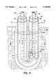
- FIG. 3is a perspective view of the heat exchanger showing operation in the heating cycle
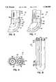
- FIG. 4is a top sectional view of the heat exchanger taken along line IV--IV of FIG. 3;
- FIG. 5is a perspective view of the heat exchanger showing operation in the cooling cycle
- FIG. 6is a partially sectional view of the heat exchanger and the bypass seal
- FIG. 7is a partially sectional view of the heat exchanger and an alternative bypass seal
- FIG. 8is a perspective view of an alternative heat exchanger
- FIG. 9is a schematic diagram of an alternative heat pump circuit.
- FIGS. 1 and 2A heat pump system constructed in accordance with a preferred embodiment of the present invention is illustrated in FIGS. 1 and 2, and generally designated 10.
- the heat pump system 10operates to either cool or heat a space 22 by transferring heat to and from an outside heat source/sink, such as the earth 38.
- the system 10includes a generally conventional heat pump circuit 12 having an air handler coil 14, a compressor 16, a reversing valve 18; an accumulator 20, a number of manifolds 24, 26, and 28, a number of heat exchangers 32a-d, and a network of conventional refrigerant lines 36 interconnecting the various components. Except as described below, the operation and interrelationship of these components is generally well known to those skilled in the art. Accordingly, the individual components will not be discussed in detail. However, a general summary of the function of each of these components will be provided.
- the compressor 16pumps a refrigerant through the heat pump circuit 12. As the refrigerant circulates, it abstracts, releases, and caries heat throughout the circuit. In the cooling cycle, the refrigerant abstracts heat from the conditioned space 22 and dissipates it into the earth 38. In the heating cycle, the refrigerant abstracts heat from the earth 38 and releases it into the conditioned space 22.
- compressor 16, reversing valve 18, and accumulator 20are contained in a cabinet 35 located outside of space 22. However, the location of these components is not important. For example, any of these components can be located within space 22, and in many applications the compressor and air handler coil can be an integral unit.
- the air handler coil 14is located in the conditioned space 22 to transfer heat between the refrigerant and the conditioned space 22.
- the air handler coilfunctions as a condensor where vaporized refrigerant is cooled and changed into a liquid.
- the refrigerantreleases a significant amount of heat into the space 22.
- the air handler coilfunctions as an evaporator where liquid refrigerant is heated and changed into a vapor.
- the refrigerantabstracts a significant amount of heat from the space 22.
- the heat exchangers 32a-dare typically buried in the earth 38 or submerged in an outside water source such as a well, river, stream, or lake.
- the heat exchangers 32a-dtransfer heat between the refrigerant and the heat source/sink, in this case the earth 38.
- the heat exchangersfunction as an evaporator where liquid refrigerant is heated and changed into a vapor.
- a significant amount of heatis abstracted from the earth 38.
- the heat exchangersfunction as a condensor where vaporized refrigerant is cooled and changed into a liquid.
- a significant amount of heatis dissipated into the earth 38.
- the reversing valve 18switches the system 10 between the heating and cooling cycles.
- the reversing valve 18directs the refrigerant from the compressor 16 to the air handler coil 14.
- the refrigerantflows to the heat exchangers 32a-d through manifolds 24 and 26.
- the refrigerantthen flows from the heat exchangers to the reversing valve through manifold 28.
- the reversing valve 18directs the returning refrigerant through the accumulator 20 and back to the compressor 16.
- the flowis essentially reversed.
- the refrigerant from the compressor 16is directed to the heat exchangers 32a-d via manifold 28.
- the refrigerantflows from the heat exchangers 32a-d to the air handler coil 14 through manifold 24. From the air handler coil 14, the refrigerant returns to the reversing valve 18 which directs it to the accumulator 20 and back to the compressor 16.
- Accumulator 20prevents liquid refrigerant from flowing into and possibly damaging the compressor. As refrigerant enters accumulator 20, the liquid refrigerant falls into the reservoir where it is stored while the vaporized refrigerant is free to exit the accumulator and flow to compressor 16.
- a receiver(not shown) or other conventional component for storing excess refrigerant during the heating or cooling cycle.
- the manifolds 24, 26, and 28are typically housed in a pit 34 located adjacent to the heat exchangers 32a-d.
- the manifolds 24, 26, and 28allow the desired number of heat exchangers 32a-d to be connected in parallel to the heat pump system 10.
- the refrigerant line networkis generally conventional except for the pump down circuitry described below. Suffice it to say that the network is comprised of copper tubing or other suitable materials that interconnect the various circuit components in a conventional manner.
- the networkincludes line 100 interconnecting compressor 16 and reversing valve 18, line 102 interconnecting reversing valve 18 and air handler coil 14, line 104 interconnecting air handler coil 14 and splitter 128 (described below), lines 106 and 108 interconnecting splitter 128 with manifolds 24 and 26, lines 110 and 112 interconnecting manifolds 24 and 26 with heat exchanger 32, line 114 interconnecting heat exchanger 32 and manifold 28, line 116 interconnecting manifold 28 and reversing valve 18, line 118 interconnecting reversing valve 18 and accumulator 20, line 120 interconnecting accumulator 20 and compressor 16, and line 122 interconnecting line 108 and line 102.
- a pair of thermostatic expansion valves 40a-bare placed along line 104 to meter the flow of refrigerant.
- the expansion valves 40a-bare connected in parallel with a pair of one-way check valves 41a-b.
- the check valves 41a-bdirect refrigerant through expansion valve 40a during the heating cycle and expansion valve 40b during the cooling cycle.
- the expansion valvescan be replaced by suitable fixed orifice metering devices, capillary tubes or the like. The type and size of the metering device will be selected to provide the appropriate refrigerant flow rate.
- valve 124is placed along line 108 to allow selective control over the flow of refrigerant through line 108. Operation of valve 124 is controlled by a conventional control system (not shown). A one-way check valve 126 is placed along line 122 to prevent the flow of refrigerant from line 102 to line 108.
- Splitter 128divides the flow of refrigerant between the operating subcircuit and the pump down subcircuit during the heating cycle. Liquid refrigerant flows into splitter 128 from line 104 and out of splitter 128 through lines 106 and 108.
- splitter 128is a conventional "T" joint.
- the heat exchangers 32a-dare generally identical and, as noted above, are buried or submerged in a heat source/sink such as the earth, a well, a lake, a pond, or a stream.
- the heat exchangers 32a-dare connected in parallel to the circuit through manifolds 24, 26, and 28.
- the number of heat exchangers 32a-dwill vary from application to application depending on the desired amount of heat transfer.
- Each heat exchanger 32a-dincludes an operating subcircuit 50 and a pump down subcircuit 60 (see FIGS. 2, 3, and 5).
- Each subcircuitincludes a heat transfer tube 52, 62, connected in series with a liquid line 54, 64.
- the heat transfer tube 62 of the pump down subcircuit 60surrounds the liquid line 54 of the operating subcircuit 50.
- the heat exchanger 32includes a continuous, substantially U-shaped outer tube 42 that is divided into two discrete segments 44 and 46 by a bypass seal 70.
- the two segments 44 and 46function as heat transfer tubes 52 and 62.
- the continuous outer tube 42can be replaced by a jointed outer tube assembly.
- the liquid lines 54 and 64are of substantially smaller diameter than the outer tube 42, and extend substantially coaxially into opposite ends of the outer tube 42. Liquid line 54 is connected to manifold 24 via line 110 and liquid line 64 is connected to manifold 26 via line 112 (see FIG. 2).
- the bypass seal 70interconnects each liquid line 54 and 64 with the corresponding heat transfer tube 52 and 62, respectively.
- the outer tube and liquid linesare preferably conventional copper tubing, however, a wide variety of conventional materials will suffice.
- the two heat transfer tubes 52 and 62are interconnected by a vapor line 74 having a one-way check valve 75 that permits refrigerant to flow only from heat transfer tube 62 to heat transfer tube 52 (see FIG. 2).
- the two heat transfer tubes 52 and 62are connected to manifold 28 via line 114.
- vapor line 74 and check valve 75can be eliminated and an additional manifold (not shown) can be installed in communication with heat transfer tube 62.
- a new vapor line and check valvewould extend between the new manifold (not shown) and manifold 28 to join the refrigerant from heat transfer tubes 52 and 62.
- the heat exchanger 32preferably includes a double-wall construction that allows the heat exchanger to vent to the atmosphere.
- the outer tube 42is surrounded by a continuous secondary tube 72 that vents above-ground.
- the secondary tube 72is a polyethylene sheath fitted snugly around the outer tube 42. The open ends of the secondary tube 72 remain above-ground so that refrigerant leaking from the outer tube 42 vents above-ground.
- the system 10can be provided with conventional apparatus (not shown) for sensing the flow of refrigerant from the secondary tube 72.
- the heat exchanger 32is preferably grouted to improve heat transfer with the earth 38.
- Grout 80is well known to those skilled in the art and consequently will not be discussed in detail. Suffice it to say that volcanic clay or concrete grout is preferred.
- the bypass seal 70is fitted within the outer tube 42 to divide the outer tube 42 into segments 44 and 46.
- the location of the bypass seal 70can vary depending on the specific design of the heat pump circuit 12 and the heat exchanger 32.
- the bypass seal 70can be moved to compensate for refrigerant imbalance between the cooling and heating cycles.
- the bypass seal 70can be located on the opposite side of the "U” or at the bottom of the "U” to facilitate the return of oil to the compressor.
- the bypass seal 70includes a plug 74 and a pair of bypass openings 76a-b extending through the plug.
- the bypass seal 70is preferably manufactured from brass or copper, however, a variety of materials will suffice including a wide range of elastomers.
- Each bypass opening 76a-bincludes a circular end 78 and a half-moon end 81 (See FIG. 4).
- the liquid lines 54 and 64enter opposite sides of the bypass seal 70 through circular ends 78.
- the lines 54 and 64are brazed, soldered, compression fit, or otherwise secured to the bypass seal 70.
- the bypass openingscan be a pair of through bores 76a-b' (See FIG. 7).
- a crimp ring 82is crimped around the outside of the outer tube 42 to secure the bypass seal 70 in place.
- the bypass seal 70can be secured in place by induction brazing or soldering.
- the bypass sealcan be held in place by the liquid lines and an O-ring that also provides a seal between the plug and the outer tube 42.
- a variety of other conventional methodscan be used to secure the bypass seal 70 in place.
- the heat pump system 10operates in either a heating cycle or a cooling cycle.
- solenoid valve 124is open and reversing valve 18 is actuated to interconnect line 100 with line 102 and line 116 with line 118.
- Compressor 16pumps vaporized refrigerant through line 100 to reversing valve 18.
- the refrigerantpasses from the reversing valve to the air handler coil 14 through line 102.
- the vaporized refrigerantcondenses into a high pressure liquid thereby releasing heat energy into space 22.
- the liquid refrigerantflows from the air handler coil to the liquid line splitter 128 through line 104. As the refrigerant moves through line 104 it passes through check valve 41a and expansion valve 40a.
- Expansion valve 40ameters the refrigerant to separate the high pressure side of the circuit from the low pressure side of the circuit.
- the refrigerantthen flows through lines 106 and 108 into manifolds 24 and 26.
- Check valve 126prevents refrigerant from flowing through line 102 into line 122.
- the refrigerantflows from manifolds 24 and 26 to the heat exchanger 32 through lines 110 and 112. If more than one heat exchanger is installed, the manifolds divide the refrigerant to flow in parallel through all of the heat exchangers.
- the low pressure liquid Lflows into the liquid line 54 and 64 of both subcircuits 50 and 60.
- the liquid refrigerant Lflows from the liquid lines 54 and 64 into the heat transfer tubes 52 and 62 where the refrigerant vaporizes thereby abstracting heat from the earth 38 (See FIG. 3).
- the vaporized refrigerant Vflows from heat transfer tube 62 through vapor line 74 and check valve 75 where it unites with the vaporized refrigerant from heat transfer tube 52.
- the vaporized refrigerantflows to manifold 28 via line 114. If more than one heat exchanger is installed, the vaporized refrigerant from all of the heat exchangers will return to manifold 28. From manifold 28, the refrigerant flows to the reversing valve 18 through line 116 and then to the accumulator 20 through line 118. The refrigerant then flows back to the compressor 16 via line 120 to complete the circuit.
- solenoid valve 124is closed and the reversing valve 18 is actuated to interconnect line 100 with line 116 and line 102 with line 118.
- the compressor 16pumps vaporized refrigerant through line 100 to reversing valve 18.
- the reversing valvedirects the refrigerant to manifold 28 via line 116. From manifold 28, the vaporized refrigerant V flows through line 114 into heat transfer tube 52.
- Check valve 75prevents the refrigerant from entering heat transfer tube 62.
- the vaporized refrigerant Vcondenses in heat transfer tube 52 and the resulting liquid L is forced up through liquid line 54 (See FIG. 5).
- the liquid refrigerantflows to manifold 24 through line 110.
- the liquid refrigerantflows to the air handler coil 14 through line 106, liquid line splitter 128, and line 104.
- Solenoid valve 124is closed to prevent refrigerant from flowing through line 108.
- Expansion valve 40bmeters the refrigerant to separate the high pressure side of the circuit from the low pressure side of the circuit.
- the refrigerantvaporizes thereby abstracting heat from space 22.
- the vaporized refrigerantthen flows from the air handler coil to the reversing valve 18 via line 102.
- the reversing valvedirects the refrigerant to the accumulator 20 through line 118.
- the refrigerantflows back to the compressor via line 120.
- the pump down subcircuit 60is "pumped down" to insulate liquid line 54 from the heat dissipated during condensation of the vaporized refrigerant in heat transfer tube 52.
- the low pressure in line 102draws refrigerant from the pump down subcircuit via lines 122, 108, and 112, leaving only low density vaporized refrigerant.
- the refrigerant drawn from the pump down subcircuitcan be used by the circuit to overcome the refrigerant imbalance.
- the double wall constructionprotects the environment from leaking refrigerant. If at any time the outer tube 42 begins to leak, the escaping refrigerant will be trapped between the outer tube 42 and the secondary tube 72. The trapped refrigerant will flow between the two tubes until it reaches either or both open ends of the secondary tube 72. A leak can be detected by a sensing device or by visual inspection of the receptacle.
- the heat exchangeris modified to locate both liquid lines in a single heat transfer tube.
- liquid line 54is replaced by liquid line 54".
- Liquid line 54"includes an open end 55 that communicates with heat transfer tube 52".
- the bypass seal 70"is modified to include only a single bypass opening 76a" adapted to connect liquid line 64" with heat transfer tube 62".
- Operation of the alternate heat exchanger 32"is generally identical to that of the preferred embodiment.
- refrigerantcirculates through both the pump down and operating subcircuits.
- the pump down subcircuitis pumped down to insulate liquid line 64" from heat dissipated during condensation of refrigerant in heat transfer tube 62".
- FIG. 9A second alternative embodiment is shown in FIG. 9.
- the heat pump circuit 12'is modified to return the liquid refrigerant drawn from the pump down subcircuit 60 to the circuit upstream from the air handler coil 14.
- solenoid valve 124, splitter 128, line 106, and line 108are eliminated. These components are replaced by a single line 104' extending between air handler coil 14 and manifold 24, a single line 122' extending between manifold 26 and line 104' (between expansion valve 40b and air handler coil 14), and expansion valve 130 placed along line 122' in parallel with check valve 126 to separate the high and low pressure sides of the circuit.
- refrigerantis free to flow out of the pump down subcircuit 60 through check valve 126.
- the flow of refrigerantis reversed and the refrigerant flows into the pump down subcircuit through expansion valve 130.
- the present inventionis described in conjunction with a space conditioning system. Those skilled in the art will readily appreciate and understand that the present invention is equally well suited for use with water heating systems, heat disposal systems, and other similar heating and/or cooling systems.
Landscapes
- Engineering & Computer Science (AREA)
- Mechanical Engineering (AREA)
- General Engineering & Computer Science (AREA)
- Life Sciences & Earth Sciences (AREA)
- Sustainable Development (AREA)
- Sustainable Energy (AREA)
- Chemical & Material Sciences (AREA)
- Combustion & Propulsion (AREA)
- Physics & Mathematics (AREA)
- Thermal Sciences (AREA)
- Other Air-Conditioning Systems (AREA)
Abstract
Description
Claims (15)
Priority Applications (3)
| Application Number | Priority Date | Filing Date | Title |
|---|---|---|---|
| US08/491,239US5706888A (en) | 1995-06-16 | 1995-06-16 | Geothermal heat exchanger and heat pump circuit |
| CA002178981ACA2178981C (en) | 1995-06-16 | 1996-06-14 | Heat exchanger and heat pump circuit |
| US08/905,192US5875644A (en) | 1995-06-16 | 1997-08-04 | Heat exchanger and heat pump circuit |
Applications Claiming Priority (1)
| Application Number | Priority Date | Filing Date | Title |
|---|---|---|---|
| US08/491,239US5706888A (en) | 1995-06-16 | 1995-06-16 | Geothermal heat exchanger and heat pump circuit |
Related Child Applications (1)
| Application Number | Title | Priority Date | Filing Date |
|---|---|---|---|
| US08/905,192DivisionUS5875644A (en) | 1995-06-16 | 1997-08-04 | Heat exchanger and heat pump circuit |
Publications (1)
| Publication Number | Publication Date |
|---|---|
| US5706888Atrue US5706888A (en) | 1998-01-13 |
Family
ID=23951352
Family Applications (2)
| Application Number | Title | Priority Date | Filing Date |
|---|---|---|---|
| US08/491,239Expired - LifetimeUS5706888A (en) | 1995-06-16 | 1995-06-16 | Geothermal heat exchanger and heat pump circuit |
| US08/905,192Expired - LifetimeUS5875644A (en) | 1995-06-16 | 1997-08-04 | Heat exchanger and heat pump circuit |
Family Applications After (1)
| Application Number | Title | Priority Date | Filing Date |
|---|---|---|---|
| US08/905,192Expired - LifetimeUS5875644A (en) | 1995-06-16 | 1997-08-04 | Heat exchanger and heat pump circuit |
Country Status (2)
| Country | Link |
|---|---|
| US (2) | US5706888A (en) |
| CA (1) | CA2178981C (en) |
Cited By (59)
| Publication number | Priority date | Publication date | Assignee | Title |
|---|---|---|---|---|
| US6085536A (en)* | 1999-08-12 | 2000-07-11 | Evans, Sr.; Fred | Environmentally adaptive VAC exterior heat exchange unit |
| US6167715B1 (en)* | 1998-10-06 | 2001-01-02 | Thomas H. Hebert | Direct refrigerant geothermal heat exchange or multiple source subcool/postheat/precool system therefor |
| US6251179B1 (en) | 1999-03-23 | 2001-06-26 | The United States Of America As Represented By The Department Of Energy | Thermally conductive cementitious grout for geothermal heat pump systems |
| US6250371B1 (en) | 1995-09-12 | 2001-06-26 | Enlink Geoenergy Services, Inc. | Energy transfer systems |
| US6267172B1 (en) | 2000-02-15 | 2001-07-31 | Mcclung, Iii Guy L. | Heat exchange systems |
| US6276438B1 (en) | 1995-09-12 | 2001-08-21 | Thomas R. Amerman | Energy systems |
| US6295827B1 (en)* | 1998-09-24 | 2001-10-02 | Exxonmobil Upstream Research Company | Thermodynamic cycle using hydrostatic head for compression |
| US6585036B2 (en) | 1995-09-12 | 2003-07-01 | Enlink Geoenergy Services, Inc. | Energy systems |
| US6585047B2 (en) | 2000-02-15 | 2003-07-01 | Mcclung, Iii Guy L. | System for heat exchange with earth loops |
| US6604577B2 (en)* | 2000-12-05 | 2003-08-12 | Eric P. Mulder | Geothermal heat pump cleaning control system and method |
| US20030183375A1 (en)* | 2002-03-29 | 2003-10-02 | Clarksean Randy Lee | PCM (phase change material) system and method for shifting peak electrical load |
| US20030209340A1 (en)* | 2000-02-15 | 2003-11-13 | Mcclung Guy L. | Microorganism enhancement with earth loop heat exchange systems |
| US6672371B1 (en)* | 1995-09-12 | 2004-01-06 | Enlink Geoenergy Services, Inc. | Earth heat exchange system |
| US20040031585A1 (en)* | 1995-09-12 | 2004-02-19 | Johnson Howard E. | Earth loop energy systems |
| US20040129408A1 (en)* | 2002-09-20 | 2004-07-08 | Wiggs B. Ryland | Insulated sub-surface liquid line direct expansion heat exchange unit with liquid trap |
| US20040194909A1 (en)* | 2003-04-07 | 2004-10-07 | Tai-Her Yang | Natural thermo carrier fluid exchange system for heat reclaim |
| US20050006049A1 (en)* | 2003-05-30 | 2005-01-13 | Ross Mark G. | Ground source heat exchange system |
| US6860320B2 (en) | 1995-09-12 | 2005-03-01 | Enlink Geoenergy Services, Inc. | Bottom member and heat loops |
| US7146823B1 (en) | 2004-06-22 | 2006-12-12 | Earth To Air Systems, Llc | Horizontal and vertical direct exchange heating/cooling system sub-surface tubing installation means |
| US20060288724A1 (en)* | 2005-06-27 | 2006-12-28 | Geofurnace Development Inc. | Hybrid heating and cooling system |
| US20070074847A1 (en)* | 2005-09-30 | 2007-04-05 | Wiggs B R | Encasement assembly for installation of sub-surface refrigerant tubing in a direct exchange heating/cooling system |
| US20070089447A1 (en)* | 2004-06-22 | 2007-04-26 | Wiggs B R | Direct exchange geothermal heating/cooling system sub-surface tubing installation with supplemental sub-surface tubing configuration |
| US7401641B1 (en) | 2004-05-24 | 2008-07-22 | Earth To Air Systems, Llc | Vertically oriented direct exchange/geothermal heating/cooling system sub-surface tubing installation means |
| US20080173425A1 (en)* | 2007-01-18 | 2008-07-24 | Earth To Air Systems, Llc | Multi-Faceted Designs for a Direct Exchange Geothermal Heating/Cooling System |
| US20080213709A1 (en)* | 2005-11-18 | 2008-09-04 | Russell Clayton | Gas supply coupling for a water heater |
| US20080236784A1 (en)* | 2007-03-21 | 2008-10-02 | Rehau Ag & Co. | Pipe arrangement |
| CN100427853C (en)* | 2005-02-25 | 2008-10-22 | Cne株式会社 | Air conditioning and heating system with cold and warm gas operating simultaneously utilizing geothermal heat, and controlling means thereof |
| US20090065173A1 (en)* | 2007-07-16 | 2009-03-12 | Earth To Air Systems, Llc | Direct exchange heating/cooling system |
| US20090095442A1 (en)* | 2007-10-11 | 2009-04-16 | Earth To Air Systems, Llc | Advanced DX System Design Improvements |
| US20090120120A1 (en)* | 2007-11-09 | 2009-05-14 | Earth To Air, Llc | DX System with Filtered Suction Line, Low Superheat, and Oil Provisions |
| US20090120606A1 (en)* | 2007-11-08 | 2009-05-14 | Earth To Air, Llc | Double DX Hydronic System |
| US7578140B1 (en) | 2003-03-20 | 2009-08-25 | Earth To Air Systems, Llc | Deep well/long trench direct expansion heating/cooling system |
| US20090260378A1 (en)* | 2008-04-21 | 2009-10-22 | Earth To Air Systems, Llc | DX System Heat to Cool Valves and Line Insulation |
| US20090272137A1 (en)* | 2008-05-02 | 2009-11-05 | Earth To Air Systems, Llc | Oil Return, Superheat and Insulation Design |
| US20100212858A1 (en)* | 2009-02-26 | 2010-08-26 | David Guth | Geothermal Cooling System for an Energy-Producing Plant |
| US20100230071A1 (en)* | 2009-08-12 | 2010-09-16 | Hal Slater | Geothermal Water Heater |
| US20100230072A1 (en)* | 2008-09-12 | 2010-09-16 | Carlin Martin A | Geothermal system for heating a home or building |
| US7832220B1 (en) | 2003-01-14 | 2010-11-16 | Earth To Air Systems, Llc | Deep well direct expansion heating and cooling system |
| US7841200B1 (en) | 2003-05-19 | 2010-11-30 | Earth To Air Systems, Llc | Sub-surface tubing spacer means for direct expansion heating/cooling systems |
| US20110100588A1 (en)* | 2008-05-14 | 2011-05-05 | Earth To Air Systems, Llc | DX System Interior Heat Exchanger Defrost Design for Heat to Cool Mode |
| US20110209848A1 (en)* | 2008-09-24 | 2011-09-01 | Earth To Air Systems, Llc | Heat Transfer Refrigerant Transport Tubing Coatings and Insulation for a Direct Exchange Geothermal Heating/Cooling System and Tubing Spool Core Size |
| WO2012129331A1 (en)* | 2011-03-21 | 2012-09-27 | Nikola Lakic | Self-contained in-ground geothermal generator |
| US20120247719A1 (en)* | 2005-03-09 | 2012-10-04 | John E Kidwell | Method of and apparatus for transferring heat energy between a heat exchanging subsystem above the surface of the earth and material therebeneath using one or more coaxial-flow heat exchanging structures producing turbulence in aqueous-based heat-transfering fluid flowing along helically-extending outer flow channels formed therein |
| WO2013112900A3 (en)* | 2012-01-27 | 2014-05-08 | Deep Well Power, LLC | Single well, self-flowing geothermal system for energy extraction |
| US20150060073A1 (en)* | 2013-09-05 | 2015-03-05 | Saudi Arabian Oil Company | Method of using concentrated solar power (csp) for thermal gas well deliquification |
| US8997509B1 (en) | 2010-03-10 | 2015-04-07 | B. Ryland Wiggs | Frequent short-cycle zero peak heat pump defroster |
| US9080789B2 (en) | 2010-05-05 | 2015-07-14 | Greensleeves, LLC | Energy chassis and energy exchange device |
| US20170248333A1 (en)* | 2016-02-26 | 2017-08-31 | American Water Works Company, Inc. | Geothermal heating and cooling system |
| US20170292792A1 (en)* | 2014-09-02 | 2017-10-12 | Japan New Energy Co., Ltd. | Geothermal heat exchanger, liquid transport pipe, liquid raising pipe, geothermal power generation facility, and geothermal power generation method |
| US10015906B1 (en)* | 2016-05-10 | 2018-07-03 | Cristofer D. Somerville | Geo-thermal inverter cooling system |
| US10387581B2 (en) | 2013-09-05 | 2019-08-20 | Greensleeves, LLC | System for optimization of building heating and cooling systems |
| US11098926B2 (en) | 2007-06-28 | 2021-08-24 | Nikola Lakic | Self-contained in-ground geothermal generator and heat exchanger with in-line pump used in several alternative applications including the restoration of the salton sea |
| US11927377B2 (en) | 2014-09-26 | 2024-03-12 | Waterfurnace International, Inc. | Air conditioning system with vapor injection compressor |
| US11953239B2 (en) | 2018-08-29 | 2024-04-09 | Waterfurnace International, Inc. | Integrated demand water heating using a capacity modulated heat pump with desuperheater |
| US12013155B2 (en) | 2007-06-28 | 2024-06-18 | Nikola Lakic | Self-contained in-ground geothermal generator and heat exchanger with in-line pump used in several alternative applications including the restoration of the Salton Sea |
| US12169085B2 (en) | 2019-07-15 | 2024-12-17 | Climate Master, Inc. | Air conditioning system with capacity control and controlled hot water generation |
| US12181179B2 (en) | 2016-11-09 | 2024-12-31 | Climate Master, Inc. | Hybrid heat pump with improved dehumidification |
| US12181194B2 (en) | 2016-07-08 | 2024-12-31 | Climate Master, Inc. | Heat pump and water heater |
| US12181189B2 (en) | 2021-11-10 | 2024-12-31 | Climate Master, Inc. | Ceiling-mountable heat pump system |
Families Citing this family (16)
| Publication number | Priority date | Publication date | Assignee | Title |
|---|---|---|---|---|
| US7080524B2 (en)* | 2002-12-31 | 2006-07-25 | B. Ryland Wiggs | Alternate sub-surface and optionally accessible direct expansion refrigerant flow regulating device |
| US6751974B1 (en)* | 2002-12-31 | 2004-06-22 | B. Ryland Wiggs | Sub-surface and optionally accessible direct expansion refrigerant flow regulating device |
| CA2479720C (en)* | 2004-08-26 | 2007-03-13 | Dryair Inc. | Reversing circulation for heating and cooling conduits |
| DE102005011239A1 (en)* | 2005-03-11 | 2006-09-14 | Blz Geotechnik Gmbh | Geothermal energy plant operating method, by extracting heat from the system and inputting heat to the system simultaneously or with a time offset |
| US7757508B2 (en)* | 2005-08-31 | 2010-07-20 | Ut-Battelle, Llc | Super energy saver heat pump with dynamic hybrid phase change material |
| US7617697B2 (en)* | 2006-05-16 | 2009-11-17 | Mccaughan Michael | In-ground geothermal heat pump system |
| GB2450754B8 (en)* | 2007-07-06 | 2013-02-06 | Greenfield Energy Ltd | Geothermal energy system and method of operation |
| GB2450755B (en) | 2007-07-06 | 2012-02-29 | Greenfield Energy Ltd | Geothermal energy system and method of operation |
| WO2009012328A1 (en)* | 2007-07-16 | 2009-01-22 | Earth To Air Systems, Llc | Direct exchange system design improvements |
| NL1035252C2 (en)* | 2008-04-03 | 2009-10-06 | Otte Holding B V M | Device for collecting used tap water and / or rain water and a system for extracting residual heat from it. |
| GB2461029B (en)* | 2008-06-16 | 2011-10-26 | Greenfield Energy Ltd | Thermal energy system and method of operation |
| US20090321040A1 (en)* | 2008-06-26 | 2009-12-31 | Poitras Joshua J | Methods and systems for hole reclamation for power generation via geo-saturation of secondary working fluids |
| JP5268946B2 (en)* | 2008-06-30 | 2013-08-21 | 東海ゴム工業株式会社 | Fluid-filled vibration isolator and control method for automobile engine mount using the same |
| DE202010005384U1 (en)* | 2010-05-05 | 2010-10-14 | Iff Kollmannsberger Kg | Connecting device for connecting a heat source to a heat pump cycle |
| GB2488797A (en) | 2011-03-08 | 2012-09-12 | Greenfield Master Ipco Ltd | Thermal Energy System and Method of Operation |
| WO2013064162A1 (en)* | 2011-11-03 | 2013-05-10 | Bartz Joergen | Method and system for generating electric power and optionally heat from geothermal energy or terrestrial heat |
Citations (20)
| Publication number | Priority date | Publication date | Assignee | Title |
|---|---|---|---|---|
| GB196993A (en)* | 1922-01-31 | 1923-04-30 | Frederick William Atack | Improved process for sulphurising organic compounds |
| US1554654A (en)* | 1923-03-24 | 1925-09-22 | Instant Water Heater Company | Water-heating device |
| US1597618A (en)* | 1926-08-24 | Diana | ||
| US3882937A (en)* | 1973-09-04 | 1975-05-13 | Union Oil Co | Method and apparatus for refrigerating wells by gas expansion |
| US4171721A (en)* | 1977-11-11 | 1979-10-23 | Movick Nyle O | Refrigeration apparatus |
| DE2911425A1 (en)* | 1979-03-23 | 1980-09-25 | Brocks | Ground heat exchange cell - has tubular body closed at bottom containing inner pipe to form flushing jacket |
| US4255936A (en)* | 1978-10-20 | 1981-03-17 | Cochran Robert W | Heat pump water heater |
| US4286651A (en)* | 1980-04-28 | 1981-09-01 | Environmental Impact Research Group | Geothermal heating system and method of installing the same |
| DE3015149A1 (en)* | 1980-04-19 | 1981-10-22 | Stiebel Eltron Gmbh & Co Kg, 3450 Holzminden | Heat exchanger driven into soil for heat pump - has filler material between casing and fluid pipes |
| DE3022588A1 (en)* | 1980-06-16 | 1981-12-24 | Hans 4407 Emsdetten Hinterding | Underground heat extraction tube for heat pump - has insulation around inner and outer water circulating pipes to reduce heat losses |
| US4325228A (en)* | 1980-05-20 | 1982-04-20 | Wolf Herman B | Geothermal heating and cooling system |
| JPS57187557A (en)* | 1981-05-13 | 1982-11-18 | Masaru Asai | Apparatus for heat exchange of water with ground utilizing double pipe |
| DE3142347A1 (en)* | 1981-10-26 | 1983-05-05 | Walter 8200 Rosenheim Müller | Earth-heat collector as heat source for heat pumps |
| DE3203526A1 (en)* | 1982-02-03 | 1983-08-11 | Baldus, Helmut, 5430 Montabaur | Air-conditioning plant |
| US4512156A (en)* | 1977-09-30 | 1985-04-23 | Kyoto Central Co. Ltd. | Geothermal energy conversion system |
| US4671351A (en)* | 1985-07-17 | 1987-06-09 | Vertech Treatment Systems, Inc. | Fluid treatment apparatus and heat exchanger |
| US4714108A (en)* | 1985-05-13 | 1987-12-22 | Pyramid Industries, Inc. | Heat pump system |
| US5313804A (en)* | 1993-04-23 | 1994-05-24 | Maritime Geothermal Ltd. | Direct expansion geothermal heat pump |
| US5388419A (en)* | 1993-04-23 | 1995-02-14 | Maritime Geothermal Ltd. | Staged cooling direct expansion geothermal heat pump |
| US5560220A (en)* | 1995-09-01 | 1996-10-01 | Ecr Technologies, Inc. | Method for testing an earth tap heat exchanger and associated apparatus |
Family Cites Families (3)
| Publication number | Priority date | Publication date | Assignee | Title |
|---|---|---|---|---|
| JPS5345575A (en)* | 1976-10-06 | 1978-04-24 | Seiko Epson Corp | Electronic wristwatch |
| US4173865A (en)* | 1978-04-25 | 1979-11-13 | General Electric Company | Auxiliary coil arrangement |
| DE3514781C2 (en)* | 1985-04-24 | 1987-03-12 | Bayerische Motoren Werke AG, 8000 München | Air conditioning system for motor vehicles, in particular for passenger cars, with a circuit that can be switched from cooling to heating via a switching device |
- 1995
- 1995-06-16USUS08/491,239patent/US5706888A/ennot_activeExpired - Lifetime
- 1996
- 1996-06-14CACA002178981Apatent/CA2178981C/ennot_activeExpired - Fee Related
- 1997
- 1997-08-04USUS08/905,192patent/US5875644A/ennot_activeExpired - Lifetime
Patent Citations (20)
| Publication number | Priority date | Publication date | Assignee | Title |
|---|---|---|---|---|
| US1597618A (en)* | 1926-08-24 | Diana | ||
| GB196993A (en)* | 1922-01-31 | 1923-04-30 | Frederick William Atack | Improved process for sulphurising organic compounds |
| US1554654A (en)* | 1923-03-24 | 1925-09-22 | Instant Water Heater Company | Water-heating device |
| US3882937A (en)* | 1973-09-04 | 1975-05-13 | Union Oil Co | Method and apparatus for refrigerating wells by gas expansion |
| US4512156A (en)* | 1977-09-30 | 1985-04-23 | Kyoto Central Co. Ltd. | Geothermal energy conversion system |
| US4171721A (en)* | 1977-11-11 | 1979-10-23 | Movick Nyle O | Refrigeration apparatus |
| US4255936A (en)* | 1978-10-20 | 1981-03-17 | Cochran Robert W | Heat pump water heater |
| DE2911425A1 (en)* | 1979-03-23 | 1980-09-25 | Brocks | Ground heat exchange cell - has tubular body closed at bottom containing inner pipe to form flushing jacket |
| DE3015149A1 (en)* | 1980-04-19 | 1981-10-22 | Stiebel Eltron Gmbh & Co Kg, 3450 Holzminden | Heat exchanger driven into soil for heat pump - has filler material between casing and fluid pipes |
| US4286651A (en)* | 1980-04-28 | 1981-09-01 | Environmental Impact Research Group | Geothermal heating system and method of installing the same |
| US4325228A (en)* | 1980-05-20 | 1982-04-20 | Wolf Herman B | Geothermal heating and cooling system |
| DE3022588A1 (en)* | 1980-06-16 | 1981-12-24 | Hans 4407 Emsdetten Hinterding | Underground heat extraction tube for heat pump - has insulation around inner and outer water circulating pipes to reduce heat losses |
| JPS57187557A (en)* | 1981-05-13 | 1982-11-18 | Masaru Asai | Apparatus for heat exchange of water with ground utilizing double pipe |
| DE3142347A1 (en)* | 1981-10-26 | 1983-05-05 | Walter 8200 Rosenheim Müller | Earth-heat collector as heat source for heat pumps |
| DE3203526A1 (en)* | 1982-02-03 | 1983-08-11 | Baldus, Helmut, 5430 Montabaur | Air-conditioning plant |
| US4714108A (en)* | 1985-05-13 | 1987-12-22 | Pyramid Industries, Inc. | Heat pump system |
| US4671351A (en)* | 1985-07-17 | 1987-06-09 | Vertech Treatment Systems, Inc. | Fluid treatment apparatus and heat exchanger |
| US5313804A (en)* | 1993-04-23 | 1994-05-24 | Maritime Geothermal Ltd. | Direct expansion geothermal heat pump |
| US5388419A (en)* | 1993-04-23 | 1995-02-14 | Maritime Geothermal Ltd. | Staged cooling direct expansion geothermal heat pump |
| US5560220A (en)* | 1995-09-01 | 1996-10-01 | Ecr Technologies, Inc. | Method for testing an earth tap heat exchanger and associated apparatus |
Cited By (93)
| Publication number | Priority date | Publication date | Assignee | Title |
|---|---|---|---|---|
| US6672371B1 (en)* | 1995-09-12 | 2004-01-06 | Enlink Geoenergy Services, Inc. | Earth heat exchange system |
| US6250371B1 (en) | 1995-09-12 | 2001-06-26 | Enlink Geoenergy Services, Inc. | Energy transfer systems |
| US6860320B2 (en) | 1995-09-12 | 2005-03-01 | Enlink Geoenergy Services, Inc. | Bottom member and heat loops |
| US6276438B1 (en) | 1995-09-12 | 2001-08-21 | Thomas R. Amerman | Energy systems |
| US7017650B2 (en) | 1995-09-12 | 2006-03-28 | Enlink Geoenergy Services, Inc. | Earth loop energy systems |
| US6585036B2 (en) | 1995-09-12 | 2003-07-01 | Enlink Geoenergy Services, Inc. | Energy systems |
| US20040031585A1 (en)* | 1995-09-12 | 2004-02-19 | Johnson Howard E. | Earth loop energy systems |
| US6295827B1 (en)* | 1998-09-24 | 2001-10-02 | Exxonmobil Upstream Research Company | Thermodynamic cycle using hydrostatic head for compression |
| US6494251B2 (en) | 1998-09-24 | 2002-12-17 | Exxonmobil Upstream Research Company | Thermodynamic cycle using hydrostatic head for compression |
| US6167715B1 (en)* | 1998-10-06 | 2001-01-02 | Thomas H. Hebert | Direct refrigerant geothermal heat exchange or multiple source subcool/postheat/precool system therefor |
| US6251179B1 (en) | 1999-03-23 | 2001-06-26 | The United States Of America As Represented By The Department Of Energy | Thermally conductive cementitious grout for geothermal heat pump systems |
| US6085536A (en)* | 1999-08-12 | 2000-07-11 | Evans, Sr.; Fred | Environmentally adaptive VAC exterior heat exchange unit |
| US20100243201A1 (en)* | 2000-02-15 | 2010-09-30 | Mcclung Iii Guy Lamonte | Earth heat transfer loop apparatus |
| US20030209340A1 (en)* | 2000-02-15 | 2003-11-13 | Mcclung Guy L. | Microorganism enhancement with earth loop heat exchange systems |
| US20070119592A1 (en)* | 2000-02-15 | 2007-05-31 | Mcclung Guy L Iii | Earth heat transfer loop apparatus |
| US6585047B2 (en) | 2000-02-15 | 2003-07-01 | Mcclung, Iii Guy L. | System for heat exchange with earth loops |
| US6338381B1 (en) | 2000-02-15 | 2002-01-15 | Mcclung, Iii Guy L. | Heat exchange systems |
| US8176971B2 (en) | 2000-02-15 | 2012-05-15 | Mcclung Iii Guy Lamonte | Earth heat transfer loop apparatus |
| US6267172B1 (en) | 2000-02-15 | 2001-07-31 | Mcclung, Iii Guy L. | Heat exchange systems |
| US6896054B2 (en) | 2000-02-15 | 2005-05-24 | Mcclung, Iii Guy L. | Microorganism enhancement with earth loop heat exchange systems |
| US7128156B2 (en) | 2000-02-15 | 2006-10-31 | Mcclung Iii Guy L | Wellbore rig with heat transfer loop apparatus |
| US20050205260A1 (en)* | 2000-02-15 | 2005-09-22 | Mcclung Guy L Iii | Wellbore rig with heat transfer loop apparatus |
| US6604577B2 (en)* | 2000-12-05 | 2003-08-12 | Eric P. Mulder | Geothermal heat pump cleaning control system and method |
| US20030183375A1 (en)* | 2002-03-29 | 2003-10-02 | Clarksean Randy Lee | PCM (phase change material) system and method for shifting peak electrical load |
| US7096929B2 (en)* | 2002-03-29 | 2006-08-29 | Leading Technology Designs, Inc. | PCM (phase change material) system and method for shifting peak electrical load |
| US20040129408A1 (en)* | 2002-09-20 | 2004-07-08 | Wiggs B. Ryland | Insulated sub-surface liquid line direct expansion heat exchange unit with liquid trap |
| US6932149B2 (en)* | 2002-09-20 | 2005-08-23 | B. Ryland Wiggs | Insulated sub-surface liquid line direct expansion heat exchange unit with liquid trap |
| WO2004027333A3 (en)* | 2002-09-20 | 2004-09-16 | B Ryland Wiggs | Insulated sub-surface liquid line direct expansion heat exchange unit with liquid trap |
| US7832220B1 (en) | 2003-01-14 | 2010-11-16 | Earth To Air Systems, Llc | Deep well direct expansion heating and cooling system |
| US7578140B1 (en) | 2003-03-20 | 2009-08-25 | Earth To Air Systems, Llc | Deep well/long trench direct expansion heating/cooling system |
| US7004231B2 (en)* | 2003-04-07 | 2006-02-28 | Tai-Her Yang | Natural thermo carrier fluid exchange system for heat reclaim |
| US20040194909A1 (en)* | 2003-04-07 | 2004-10-07 | Tai-Her Yang | Natural thermo carrier fluid exchange system for heat reclaim |
| US7841200B1 (en) | 2003-05-19 | 2010-11-30 | Earth To Air Systems, Llc | Sub-surface tubing spacer means for direct expansion heating/cooling systems |
| US7571762B2 (en) | 2003-05-30 | 2009-08-11 | 1438253 Ontario Inc. | Ground source heat exchange system |
| US7407003B2 (en)* | 2003-05-30 | 2008-08-05 | 1438253 Ontario Inc. | Ground source heat exchange system |
| US20070051492A1 (en)* | 2003-05-30 | 2007-03-08 | Ross Mark G | Ground source heat exchange system |
| US20050006049A1 (en)* | 2003-05-30 | 2005-01-13 | Ross Mark G. | Ground source heat exchange system |
| US7401641B1 (en) | 2004-05-24 | 2008-07-22 | Earth To Air Systems, Llc | Vertically oriented direct exchange/geothermal heating/cooling system sub-surface tubing installation means |
| US20070089447A1 (en)* | 2004-06-22 | 2007-04-26 | Wiggs B R | Direct exchange geothermal heating/cooling system sub-surface tubing installation with supplemental sub-surface tubing configuration |
| US7856839B2 (en) | 2004-06-22 | 2010-12-28 | Earth To Air Systems, Llc | Direct exchange geothermal heating/cooling system sub-surface tubing installation with supplemental sub-surface tubing configuration |
| US7146823B1 (en) | 2004-06-22 | 2006-12-12 | Earth To Air Systems, Llc | Horizontal and vertical direct exchange heating/cooling system sub-surface tubing installation means |
| CN100427853C (en)* | 2005-02-25 | 2008-10-22 | Cne株式会社 | Air conditioning and heating system with cold and warm gas operating simultaneously utilizing geothermal heat, and controlling means thereof |
| US20120247719A1 (en)* | 2005-03-09 | 2012-10-04 | John E Kidwell | Method of and apparatus for transferring heat energy between a heat exchanging subsystem above the surface of the earth and material therebeneath using one or more coaxial-flow heat exchanging structures producing turbulence in aqueous-based heat-transfering fluid flowing along helically-extending outer flow channels formed therein |
| US7228696B2 (en)* | 2005-06-27 | 2007-06-12 | Geofurnace Development Inc. | Hybrid heating and cooling system |
| US20060288724A1 (en)* | 2005-06-27 | 2006-12-28 | Geofurnace Development Inc. | Hybrid heating and cooling system |
| US20070074847A1 (en)* | 2005-09-30 | 2007-04-05 | Wiggs B R | Encasement assembly for installation of sub-surface refrigerant tubing in a direct exchange heating/cooling system |
| US7841383B2 (en)* | 2005-09-30 | 2010-11-30 | Earth To Air Systems, Llc | Encasement assembly for installation of sub-surface refrigerant tubing in a direct exchange heating/cooling system |
| US20080213709A1 (en)* | 2005-11-18 | 2008-09-04 | Russell Clayton | Gas supply coupling for a water heater |
| US20080173425A1 (en)* | 2007-01-18 | 2008-07-24 | Earth To Air Systems, Llc | Multi-Faceted Designs for a Direct Exchange Geothermal Heating/Cooling System |
| US8931295B2 (en) | 2007-01-18 | 2015-01-13 | Earth To Air Systems, Llc | Multi-faceted designs for a direct exchange geothermal heating/cooling system |
| US8167027B2 (en)* | 2007-03-21 | 2012-05-01 | Rehau Ag. & Co. | Pipe arrangement |
| US20080236784A1 (en)* | 2007-03-21 | 2008-10-02 | Rehau Ag & Co. | Pipe arrangement |
| US12013155B2 (en) | 2007-06-28 | 2024-06-18 | Nikola Lakic | Self-contained in-ground geothermal generator and heat exchanger with in-line pump used in several alternative applications including the restoration of the Salton Sea |
| US11098926B2 (en) | 2007-06-28 | 2021-08-24 | Nikola Lakic | Self-contained in-ground geothermal generator and heat exchanger with in-line pump used in several alternative applications including the restoration of the salton sea |
| US20090065173A1 (en)* | 2007-07-16 | 2009-03-12 | Earth To Air Systems, Llc | Direct exchange heating/cooling system |
| US8833098B2 (en) | 2007-07-16 | 2014-09-16 | Earth To Air Systems, Llc | Direct exchange heating/cooling system |
| US20090095442A1 (en)* | 2007-10-11 | 2009-04-16 | Earth To Air Systems, Llc | Advanced DX System Design Improvements |
| US8109110B2 (en) | 2007-10-11 | 2012-02-07 | Earth To Air Systems, Llc | Advanced DX system design improvements |
| US20090120606A1 (en)* | 2007-11-08 | 2009-05-14 | Earth To Air, Llc | Double DX Hydronic System |
| US8082751B2 (en) | 2007-11-09 | 2011-12-27 | Earth To Air Systems, Llc | DX system with filtered suction line, low superheat, and oil provisions |
| US20090120120A1 (en)* | 2007-11-09 | 2009-05-14 | Earth To Air, Llc | DX System with Filtered Suction Line, Low Superheat, and Oil Provisions |
| US8468842B2 (en) | 2008-04-21 | 2013-06-25 | Earth To Air Systems, Llc | DX system having heat to cool valve |
| US20090260378A1 (en)* | 2008-04-21 | 2009-10-22 | Earth To Air Systems, Llc | DX System Heat to Cool Valves and Line Insulation |
| US20090272137A1 (en)* | 2008-05-02 | 2009-11-05 | Earth To Air Systems, Llc | Oil Return, Superheat and Insulation Design |
| US8402780B2 (en) | 2008-05-02 | 2013-03-26 | Earth To Air Systems, Llc | Oil return for a direct exchange geothermal heat pump |
| US20110100588A1 (en)* | 2008-05-14 | 2011-05-05 | Earth To Air Systems, Llc | DX System Interior Heat Exchanger Defrost Design for Heat to Cool Mode |
| US8776543B2 (en) | 2008-05-14 | 2014-07-15 | Earth To Air Systems, Llc | DX system interior heat exchanger defrost design for heat to cool mode |
| US20100230072A1 (en)* | 2008-09-12 | 2010-09-16 | Carlin Martin A | Geothermal system for heating a home or building |
| US20110209848A1 (en)* | 2008-09-24 | 2011-09-01 | Earth To Air Systems, Llc | Heat Transfer Refrigerant Transport Tubing Coatings and Insulation for a Direct Exchange Geothermal Heating/Cooling System and Tubing Spool Core Size |
| US20100212858A1 (en)* | 2009-02-26 | 2010-08-26 | David Guth | Geothermal Cooling System for an Energy-Producing Plant |
| US7827814B2 (en) | 2009-08-12 | 2010-11-09 | Hal Slater | Geothermal water heater |
| US20100230071A1 (en)* | 2009-08-12 | 2010-09-16 | Hal Slater | Geothermal Water Heater |
| US8997509B1 (en) | 2010-03-10 | 2015-04-07 | B. Ryland Wiggs | Frequent short-cycle zero peak heat pump defroster |
| US10180268B2 (en) | 2010-05-05 | 2019-01-15 | Greensleeves, LLC | Energy chassis and energy exchange device |
| US9080789B2 (en) | 2010-05-05 | 2015-07-14 | Greensleeves, LLC | Energy chassis and energy exchange device |
| WO2012129331A1 (en)* | 2011-03-21 | 2012-09-27 | Nikola Lakic | Self-contained in-ground geothermal generator |
| WO2013112900A3 (en)* | 2012-01-27 | 2014-05-08 | Deep Well Power, LLC | Single well, self-flowing geothermal system for energy extraction |
| US9394771B2 (en) | 2012-01-27 | 2016-07-19 | Deep Well Power, LLC | Single well, self-flowing, geothermal system for energy extraction |
| US9777562B2 (en)* | 2013-09-05 | 2017-10-03 | Saudi Arabian Oil Company | Method of using concentrated solar power (CSP) for thermal gas well deliquification |
| US20150060073A1 (en)* | 2013-09-05 | 2015-03-05 | Saudi Arabian Oil Company | Method of using concentrated solar power (csp) for thermal gas well deliquification |
| US10387581B2 (en) | 2013-09-05 | 2019-08-20 | Greensleeves, LLC | System for optimization of building heating and cooling systems |
| US11092353B2 (en) | 2013-09-05 | 2021-08-17 | Greensleeves Technologies Corp. | System for optimization of building heating and cooling systems |
| US20170292792A1 (en)* | 2014-09-02 | 2017-10-12 | Japan New Energy Co., Ltd. | Geothermal heat exchanger, liquid transport pipe, liquid raising pipe, geothermal power generation facility, and geothermal power generation method |
| US10203162B2 (en)* | 2014-09-02 | 2019-02-12 | Japan New Energy Co., Ltd. | Geothermal heat exchanger, liquid transport pipe, liquid raising pipe, geothermal power generation facility, and geothermal power generation method |
| US11927377B2 (en) | 2014-09-26 | 2024-03-12 | Waterfurnace International, Inc. | Air conditioning system with vapor injection compressor |
| US20170248333A1 (en)* | 2016-02-26 | 2017-08-31 | American Water Works Company, Inc. | Geothermal heating and cooling system |
| US10015906B1 (en)* | 2016-05-10 | 2018-07-03 | Cristofer D. Somerville | Geo-thermal inverter cooling system |
| US12181194B2 (en) | 2016-07-08 | 2024-12-31 | Climate Master, Inc. | Heat pump and water heater |
| US12181179B2 (en) | 2016-11-09 | 2024-12-31 | Climate Master, Inc. | Hybrid heat pump with improved dehumidification |
| US11953239B2 (en) | 2018-08-29 | 2024-04-09 | Waterfurnace International, Inc. | Integrated demand water heating using a capacity modulated heat pump with desuperheater |
| US12169085B2 (en) | 2019-07-15 | 2024-12-17 | Climate Master, Inc. | Air conditioning system with capacity control and controlled hot water generation |
| US12173940B2 (en) | 2019-07-15 | 2024-12-24 | Climate Master, Inc. | Air conditioning system with capacity control and controlled hot water generation |
| US12181189B2 (en) | 2021-11-10 | 2024-12-31 | Climate Master, Inc. | Ceiling-mountable heat pump system |
Also Published As
| Publication number | Publication date |
|---|---|
| US5875644A (en) | 1999-03-02 |
| CA2178981C (en) | 2000-01-11 |
| CA2178981A1 (en) | 1996-12-17 |
Similar Documents
| Publication | Publication Date | Title |
|---|---|---|
| US5706888A (en) | Geothermal heat exchanger and heat pump circuit | |
| US5461876A (en) | Combined ambient-air and earth exchange heat pump system | |
| CA1120029A (en) | Heat pipe bag system | |
| CA2510701C (en) | Hybrid heating and cooling system | |
| US6076595A (en) | Integral heat pipe enclosure | |
| EP2940409B1 (en) | Refrigeration device and cooling unit with a defrost system | |
| US6745830B2 (en) | Heat pipe loop with pump assistance | |
| JPH01167594A (en) | Device for heat transfer | |
| JP5034435B2 (en) | vending machine | |
| CN205783400U (en) | Heat radiation assembly of air conditioner outdoor unit and air conditioner outdoor unit | |
| US11802738B2 (en) | Water cooling system | |
| CN100449244C (en) | Heat transfer system | |
| EP0354749B1 (en) | Air-cooled absorption Air-conditioner | |
| CN106051955A (en) | Heat radiation assembly of air conditioner outdoor unit and air conditioner outdoor unit | |
| US4407129A (en) | Closed loop solar collecting system operating a thermoelectric generator system | |
| RU2487063C2 (en) | Landing lunar module instrument compartment thermal control system | |
| Bugby et al. | Multi-evaporator hybrid loop heat pipe for small spacecraft thermal management | |
| JP3303644B2 (en) | Loop heat transport system | |
| GB2125158A (en) | Heat-exchanger device | |
| KR100296699B1 (en) | Ground source cooling and heating pump system using heat pipe with two headers | |
| US4354483A (en) | Closed loop solar collector system with dual reservoirs and fluid bypass | |
| WO2015048973A1 (en) | Cooling system with thermosiphon, use and method of operating such a system | |
| US4412529A (en) | Closed loop solar collector system with dual reservoirs and fluid bypass | |
| US4397300A (en) | Closed loop solar collector system with dual chamber fluid supply arrangement | |
| EP1616136A1 (en) | Refrigeration system and a method for operating such system |
Legal Events
| Date | Code | Title | Description |
|---|---|---|---|
| AS | Assignment | Owner name:GEOFORNACE SYSTEMS, INC., MICHIGAN Free format text:ASSIGNMENT OF ASSIGNORS INTEREST;ASSIGNORS:AMBS, REX K.;KIESSEL, THOMAS G.;REEL/FRAME:007583/0802 Effective date:19950615 | |
| AS | Assignment | Owner name:GEOFURNACE SYSTEMS, INC., MICHIGAN Free format text:RECORD TO CORRECT THE SPELLING THE ASSIGNEE PREVIOUSLY RECORDED.;ASSIGNORS:AMBS, REX K.;KIESSEL, THOMAS C.;REEL/FRAME:007806/0221 Effective date:19950615 | |
| AS | Assignment | Owner name:GEOFURNACE SYSTEMS, INC., MICHIGAN Free format text:CORRECTIVE ASSIGNMENT TO CORRECT ASSIGNEE ADDRESS, PREVIOUSLY RECORDED ON REEL 7806, FRAME 0221;ASSIGNORS:AMBS, REX K.;KIESSEL, THOMAS G.;REEL/FRAME:008312/0958 Effective date:19950615 | |
| STCF | Information on status: patent grant | Free format text:PATENTED CASE | |
| AS | Assignment | Owner name:GEOFURNACE DEVELOPMENT, INC., MICHIGAN Free format text:ASSIGNMENT OF ASSIGNORS INTEREST;ASSIGNOR:GEOFURNACE, INC.;REEL/FRAME:010288/0247 Effective date:19990915 | |
| AS | Assignment | Owner name:GEOFURNACE DEVELOPMENT, INC., MICHIGAN Free format text:CORRECTIVE ASSIGNMENT TO CORRECT THE NAME OF THE ASSIGNOR PREVIOUSLY RECORDED ON REEL 010288 FRAME 0247;ASSIGNOR:GEOFURNACE SYSTEMS, INC.;REEL/FRAME:010710/0367 Effective date:19990915 | |
| FEPP | Fee payment procedure | Free format text:PAT HLDR NO LONGER CLAIMS SMALL ENT STAT AS SMALL BUSINESS (ORIGINAL EVENT CODE: LSM2); ENTITY STATUS OF PATENT OWNER: SMALL ENTITY | |
| FPAY | Fee payment | Year of fee payment:4 | |
| FEPP | Fee payment procedure | Free format text:PAT HOLDER NO LONGER CLAIMS SMALL ENTITY STATUS, ENTITY STATUS SET TO UNDISCOUNTED (ORIGINAL EVENT CODE: STOL); ENTITY STATUS OF PATENT OWNER: SMALL ENTITY Free format text:PAT HOLDER CLAIMS SMALL ENTITY STATUS, ENTITY STATUS SET TO SMALL (ORIGINAL EVENT CODE: LTOS); ENTITY STATUS OF PATENT OWNER: SMALL ENTITY | |
| FPAY | Fee payment | Year of fee payment:8 | |
| FEPP | Fee payment procedure | Free format text:PAT HOLDER CLAIMS SMALL ENTITY STATUS, ENTITY STATUS SET TO SMALL (ORIGINAL EVENT CODE: LTOS); ENTITY STATUS OF PATENT OWNER: SMALL ENTITY | |
| FPAY | Fee payment | Year of fee payment:12 | |
| FEPP | Fee payment procedure | Free format text:PAYOR NUMBER ASSIGNED (ORIGINAL EVENT CODE: ASPN); ENTITY STATUS OF PATENT OWNER: SMALL ENTITY |