US5706820A - Ultrasonic transducer with reduced elevation sidelobes and method for the manufacture thereof - Google Patents
Ultrasonic transducer with reduced elevation sidelobes and method for the manufacture thereofDownload PDFInfo
- Publication number
- US5706820A US5706820AUS08/482,147US48214795AUS5706820AUS 5706820 AUS5706820 AUS 5706820AUS 48214795 AUS48214795 AUS 48214795AUS 5706820 AUS5706820 AUS 5706820A
- Authority
- US
- United States
- Prior art keywords
- width
- kerf
- kerfs
- thickness
- ultrasound transducer
- Prior art date
- Legal status (The legal status is an assumption and is not a legal conclusion. Google has not performed a legal analysis and makes no representation as to the accuracy of the status listed.)
- Expired - Lifetime
Links
Images


Classifications
- B—PERFORMING OPERATIONS; TRANSPORTING
- B06—GENERATING OR TRANSMITTING MECHANICAL VIBRATIONS IN GENERAL
- B06B—METHODS OR APPARATUS FOR GENERATING OR TRANSMITTING MECHANICAL VIBRATIONS OF INFRASONIC, SONIC, OR ULTRASONIC FREQUENCY, e.g. FOR PERFORMING MECHANICAL WORK IN GENERAL
- B06B1/00—Methods or apparatus for generating mechanical vibrations of infrasonic, sonic, or ultrasonic frequency
- B06B1/02—Methods or apparatus for generating mechanical vibrations of infrasonic, sonic, or ultrasonic frequency making use of electrical energy
- B06B1/06—Methods or apparatus for generating mechanical vibrations of infrasonic, sonic, or ultrasonic frequency making use of electrical energy operating with piezoelectric effect or with electrostriction
- B06B1/0644—Methods or apparatus for generating mechanical vibrations of infrasonic, sonic, or ultrasonic frequency making use of electrical energy operating with piezoelectric effect or with electrostriction using a single piezoelectric element
- B06B1/0648—Methods or apparatus for generating mechanical vibrations of infrasonic, sonic, or ultrasonic frequency making use of electrical energy operating with piezoelectric effect or with electrostriction using a single piezoelectric element of rectangular shape
- Y—GENERAL TAGGING OF NEW TECHNOLOGICAL DEVELOPMENTS; GENERAL TAGGING OF CROSS-SECTIONAL TECHNOLOGIES SPANNING OVER SEVERAL SECTIONS OF THE IPC; TECHNICAL SUBJECTS COVERED BY FORMER USPC CROSS-REFERENCE ART COLLECTIONS [XRACs] AND DIGESTS
- Y10—TECHNICAL SUBJECTS COVERED BY FORMER USPC
- Y10T—TECHNICAL SUBJECTS COVERED BY FORMER US CLASSIFICATION
- Y10T29/00—Metal working
- Y10T29/42—Piezoelectric device making
Definitions
- This inventionrelates to piezoelectric ultrasound transducers and more particularly to piezoelectric transducers in which the generation of undesirable sidelobes is controlled.
- the inventionalso relates to methods for manufacturing such piezoelectric transducers.
- the piezoelectric transducers of the present inventionare particularly useful in medical imaging applications.
- Ultrasound machinesare often used for observing organs in the human body. Typically, these machines contain transducer arrays for converting electrical signals into pressure waves and vice versa. Generally, the transducer array is in the form of a hand-held probe which may be adjusted in position to direct the ultrasound beam to the region of interest.
- a transducer array 10may have, for example, 128 transducer elements 12 in the azimuthal direction for generating an ultrasound beam.
- the x, y and z directionsare referred to as the azimuthal, elevation and range directions, respectively.
- the transducer element 12is typically rectangular in cross section and includes a first electrode 14, a second electrode 16, a piezoelectric layer 18 and one or more acoustic matching layers 20 and 22.
- the transducer elements 12are disposed on a backing block 24.
- a mechanical lens 26may be placed on the matching layers to help confine the generated beam in the y-z plane. Examples of prior art transducer structures are shown in Charles S. DeSiltes, Transducer Arrays Suitable for Acoustic Imaging, Ph. D. Thesis, Stanford University (1978) and Alan R. Selfridge, Design and Fabrication of Ultrasonic Transducers and Transducer Arrays, Ph. D. Thesis, Stanford University (1982).
- Terminals 28 and 30may be connected to each of the electrodes 14 and 16 for providing the electrical excitation of the element 12.
- Terminal 28may provide the hot wire or excitation signal, and terminal 30 may provide the ground.
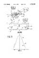
- a primary wave 31is provided in the z-direction. (see FIG. 2)
- the force distribution on the face 32 of the transducer element 12 and the acoustic and geometrical parameters of the mechanical lens 26describe the radiation pattern in the elevation direction as a function of an angle in the y-z plane.
- the finite width of the transducer element 12 in the y-directioncauses the sides 36 and 38 of the transducer element 12 to move freely. This motion in turn creates lateral waves 40 propagating along the y-direction.
- These lateral waves 40 propagating though the composite structure of piezoelectric layer 18 and matching layers 20 and 22may have a phase velocity greater than that of the external medium, i.e. the patient being examined, and may excite an undesirable secondary propagating wave and "leak" into the external medium.
- PZTlead zirconate titanate
- This "leaky" wavewill increase the sidelobe levels around the angle ⁇ .
- the phase velocity of the lateral waveis approximately 3,000 meters per second. This is approximately twice the phase velocity in the human body of 1,500 meters per second. Consequently, a secondary wave 42 caused by lateral wave 40 propagates at an angle ⁇ of 30 degrees.
- the sidelobe levels of individual elements of an ultrasound transducerare of particular concern in applications where a strong reflector in the object of interest, i.e. cartilage or an air pipe such as the trachea during the examination of the carotid artery, may be located outside the main acoustic beam.
- a strong reflector in the object of interesti.e. cartilage or an air pipe such as the trachea during the examination of the carotid artery
- the reflections from the object of interesti.e. soft tissue
- the generated imageis less accurate and may contain artifacts.
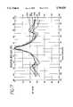
- FIG. 5is a graph illustrating the elevational or artifact sidelobe 46 generated by a transducer element such as that illustrated in FIG. 2.
- the graph in FIG. 5 as well as the graphs in FIGS. 5, 7, 9, 13-16 and 17were produced using a finite element analysis using a half cycle, 5 MHz sinusoidal excitation.
- the X axisrepresents angle in degrees and the Y axis represents decibels in dB with respect to the peak value at zero degrees.
- the graphsare symmetric about the Y axis with only one half of the graph illustrated in the Figures. It is seen that at 30° the sidelobe is only 15 db below the main lobe.
- the radiation pattern 44 of a transduceris primarily related to the field distribution across its aperture.
- the radiation patternis related to the aperture function by the Fourier transform relationship.
- For wide band excitationone may use, for example, superposition to integrate the field distributions at each frequency.
- a fixed focus lensmay scale the radiation pattern by modifying the phase of the aperture distribution but the general sidelobe characteristics are governed by the amplitude distribution of the aperture.
- apodizationmay be used to improve the radiation pattern by shaping the radiation distribution. Apodization results in varying the electric field between electrodes 14 and 16 along the elevation direction.
- these prior art techniquesfall short because lateral waves may still be generated and contribute to undesirable sidelobe levels and may result in a less accurate image.
- the lead titanate or PVDFmay be used instead of pure PZT since these materials have less thickness to lateral vibration coupling. Such materials, however, result in compromised performance, i.e. lower sensitivity and bandwidth.
- the piezoelectric layermay be modified into a composite having PZT posts embedded in a polymer matrix. Such a structure also reduces the thickness to lateral vibration coupling. However, making an entire composite block to replace the normally single phase PZT block adds considerably to the cost and complexity of manufacturing such a transducer element.
- Another methodinvolves depoling the ends of the piezoelectric layer to make them inactive. Depoling may be accomplished by exposing the ends to high temperatures, reverse electric fields or mechanically damaging the ends. Poling and depoling ceramic is a non-linear process which is difficult to control and may lead to strains in the ceramic and subsequent cracking.
- FIGS. 6 and 8illustrate the cross section of a piezoelectric layer in the elevation direction according to prior art structures used to suppress the generation of elevational sidelobes.
- FIGS. 7 and 9are graphs illustrating the effectiveness of the prior art structures shown in FIGS. 6 and 8 respectively for reducing the elevation sidelobe.
- U.S. Pat. No. 5,410,208discloses the structures shown in FIGS. 6 and 8.
- the piezoelectric layer 10have been tapered in its end regions 12 by a plurality of steps 14 as shown in the magnified view FIG. 6a.
- FIG. 7illustrates the effectiveness of tapering the end regions of the piezoelectric layer. It can be seen that the elevational sidelobe at 30° is now about 22 db below the main lobe. Fabricating tapers at the ends of the piezoelectric layer, however, is an expensive and time consuming process.
- the electrodes at the ends of the piezoelectric layerare removed along the elevation direction so as to reduce activity in the region where the elevation sidelobe wave is initiated.
- a ultrasound transducerdesigned to reduce the generation of elevational sidelobes in the emitted beam.
- the ultrasound transducerincludes a body of piezoelectric material having a width along an elevation direction and a thickness along a range direction.
- the transducer elementhas a center portion with a first width, a first end region adjacent in the elevation direction to one end of the center portion and a second end region adjacent in the elevation direction to an opposite end of the center portion.
- the first and second end regionseach has a second width smaller than the first width of the center portion.
- At least a first kerf extending parallel to azimuthal direction near the ends of the PZT bar in the elevational dimension and extends, in depth, in the range direction into the piezoelectric materialis formed in the first end region.
- At least a second kerf directionis formed in the second end region and extending parallel to azimuthal direction near the ends of the PZT bar in the elevational dimension and extends, in depth, in the range direction into the piezoelectric material.
- a second materialfills the first and second kerfs while the center portion is formed solely of piezoelectric material.
- an ultrasound transducer elementfor reducing the generation of elevational sidelobes.
- the transducerincludes a layer of ceramic having a top surface, a bottom surface, a first side surface and a second side surface.
- the top and bottom surfacesdefine a width of the layer along an elevation direction and the first and second side surfaces define a thickness of the layer along a range direction.
- a first electrodeis coupled to the top surface of the layer.
- a second electrodeis coupled to the bottom surface of the layer.
- the layer of ceramicis composed of pure PZT over a first percentage and a composite PZT over a second percentage the first percentage being greater than the second percentage.
- a method of making a transducer elementwhich reduces the generation of elevational sidelobes.
- the methodincludes providing a body of piezoelectric material having a width along an elevation direction and a thickness along a range direction, the body having a center portion having a first width and a first and second end regions having a second width; the first width being greater than the second width; dicing a first kerf in the first end region, dicing a second kerf in the second end region; and filling the first and second kerfs with a second material.
- FIG. 1is a perspective view of a transducer array according to the prior art.
- FIG. 2is a cross sectional view of the transducer array shown in FIG. 1 taken along the elevational direction illustrating the secondary wave phenomenon.
- FIG. 3is a beam plot illustrating the elevational sidelobes.
- FIG. 4is a cross-sectional view of a transducer element shown in FIG. 1.
- FIG. 5is a graph illustrating the elevational sidelobe generated by a transducer element such as that illustrated in FIG. 2.
- FIG. 6illustrates the cross section of a piezoelectric layer in the elevation direction according to prior art structure used to suppress the generation of elevational sidelobes by tapering the elevational sides of the piezoelectric layer.
- FIG. 7is a graph illustrating the effectiveness of the prior art structure shown in FIG. 6 for reducing the elevation sidelobe.
- FIG. 8illustrates the cross section of a piezoelectric layer in the elevation direction according to prior art structures used to suppress the generation of elevational sidelobes by partially removing the top electrode.
- FIG. 9is a graph illustrating the effectiveness of the prior art structure shown in FIG. 8 for reducing the elevation sidelobe.
- FIG. 10illustrates a layer of piezoelectric material according to a first preferred embodiment of the present invention.
- FIG. 11illustrates the right half of the layer of piezoelectric material shown in FIG. 10 in greater detail with the composite material.
- FIG. 12illustrates a cross-sectional view of a transducer array in the elevational direction.
- FIG. 13is a graph illustrating the effectiveness in the reduction of the generation of elevational sidelobe for a transducer element formed according to the present invention having only one kerf formed in each end region of the body of piezoelectric material.
- FIG. 14is a graph illustrating the effectiveness in the reduction of the generation of elevational sidelobe of a transducer element formed according to the present invention having two kerfs formed in each end region of the body of piezoelectric material, such as that illustrated in FIG. 10.
- FIG. 15is a graph illustrating the effectiveness in the reduction of the generation of elevational sidelobe of a transducer element formed according to the present invention having three kerfs formed in each end region of the body of piezoelectric material.
- FIG. 16is a graph illustrating the effectiveness in the reduction of the generation of elevational sidelobe of a transducer element formed according to the present invention having four kerfs formed in each end region of the body of piezoelectric material.
- FIG. 17is an elevational beam plot comparing the beam plots for transducer arrays according to the prior art as well as those according to the present invention.
- FIG. 10illustrates a layer of piezoelectric material according to a first preferred embodiment of the present invention.
- the layer of piezoelectric material 100has a width w extending in an elevation direction and a thickness t extending in a range direction.
- the width w of the layeris greater than its thickness t. In a preferred embodiment, the ratio of the layer's width to its thickness is about 30:1.
- the layer 100is formed from a body of piezoelectric material.
- kerfs 106are diced into the body of piezoelectric material.
- a center region 108is defined between the first and second end regions 102 and 104 respectively.
- the center region 108is formed solely of PZT.
- the kerfs 106 formed in the end regionsare filled with a second material 110 different from the piezoelectric layer 100, preferably an epoxy.
- the fillermay be a particle filled epoxy, for example, alumina, tungsten, tungsten oxide, lead oxide, and silica. Even glass or plastic microballoon or microsphere filled epoxy may be used. Such microballoons or microspheres are commercially available from Polysciences of Warrington, Pa.
- the kerfsmay be formed using a dicing blade or laser such as a CO 2 or excimer laser as is well known in the art.
- kerfscreate abrupt transitions in acoustic properties in the transducer element, and therefore give rise to internal reflections of any lateral waves that may be generated in the material.
- these internal reflectionsmay be made to provide maximum destructive interference in a laterally propagated wave.
- An optimum selection of kerf spacing and number of kerfsmay be determined by experimentation or by using finite element analysis. As an example, quarter wavelength center-to-center spacing, calculated using the center frequency of the transducer and the speed of the laterally propagating wave, may give an optimal result.
- FIG. 11illustrates the right half of the layer of piezoelectric material 100 shown in FIG. 10 in greater detail without the second material filling the kerfs 106.
- a layer of piezoelectric materialwas actually fabricated to have the following dimensional characteristics.
- the layer 100had a width w (see FIG. 10) in the elevation direction of about 4 mm and a thickness t in the range direction of 130 ⁇ m.
- Two kerfs 106were diced in the second end region 104 of the body of piezoelectric material.
- the kerfs 106extend, in depth in the range direction and have a depth from the top surface 112 of the piezoelectric body of about 105 ⁇ m thereby leaving a thickness t t of 25 ⁇ m under the kerfs 106.
- a plurality of transducer elementswould be positioned one behind the other in the azimuthal direction.
- the kerfs formed in the elevational end regions of the transducer segmentswould extend parallel to the azimuthal direction.
- the depth of the kerfsmay extend completely through the piezoelectric layer 100 or only partially through, for example from about 10% to 90%.
- the kerfs 106were diced having a width w K in the elevation direction of about 25 ⁇ m and a separation t s between the kerf 106' and kerf 106 of about 75 ⁇ m.
- the pitch from the center of kerf 106' to the center of the adjacent kerf 106is about 100 ⁇ m.
- the distance from the center of kerf 106' to the edge 109 of the piezoelectric layer 100is about 0.1875 mm.
- a layer of piezoelectric material having a small width of 1 mm in the elevation directionmay be constructed. If two kerfs are formed in each end region where the center-to-center spacing between adjacent kerfs is 100 ⁇ m, the center region is about 0.6 mm wide and formed of solid PZT.
- the body of piezoelectric material 100was formed of D3203HD commercially available from Motorola Ceramic Products of Albuquerque, N. Mex. PZT-5H commercially available from Morgan Matroc, Inc., of Bedford, Ohio could also be used.
- the second material (see FIG. 10) filling the kerfs 106' and 106 formed in the end regions of the body of piezoelectric materialwas preferably a polymer RE2039 with hardener HD3561 commercially available from Hysol of Industry, Calif.
- FIG. 12illustrates a cross-sectional view of a transducer array in the elevational direction.
- the transducer arrayincludes the layer of piezoelectric material 100 with a plurality of kerfs 106 filled with a second material 110 in the end regions of the body as shown in FIG. 10.
- a support member 114 in the form of a backing blockis provided with a copper flex circuit 116 disposed thereon.
- the piezoelectric assembly 100is disposed on top of the flex circuit 116.
- An acoustic matching layer 118preferably metalized is disposed above the piezoelectric assembly 100.
- the acoustic matching layer 118is formed of an alumina filled epoxy.
- More than one acoustic matching layermay be provided.
- a ground electrode 120is coupled to the ends of the acoustic matching layer 118. While there appears to be space between the various elements, there is contact between the elements.
- the matching layer 118is metalized on all surfaces so that it electrically couples the ground electrode 120 to the top surface of the piezoelectric material 100.
- the metalized matching layer 118bridges over the kerfs to electrically couple the center region 108 of the piezoelectric layer 100 to the ground electrode 120 which is coupled to the metalized matching layer 118 at its ends.
- FIG. 13is a graph illustrating the effectiveness in the reduction of the generation of elevational sidelobe for a transducer element formed according to the present invention having only one kerf formed in each end region of the body of piezoelectric material. It can be seen that the elevational sidelobe located at an angle of 30° is about 22 db lower than the main lobe centered around the origin.
- FIG. 14is a graph illustrating the effectiveness in the reduction of the generation of elevational sidelobe of a transducer element formed according to the present invention having two kerfs formed in each end region of the body of piezoelectric material, such as that illustrated in FIG. 10. It can be seen that the elevational sidelobe located at an angle of 25° is about 22 db lower than the main lobe centered around the origin.
- FIG. 15is a graph illustrating the effectiveness in the reduction of the generation of elevational sidelobe of a transducer element formed according to the present invention having three kerfs formed in each end region of the body of piezoelectric material. It can be seen that the elevational sidelobe located at an angle of 30° is about 22 db lower than the main lobe centered around the origin.
- FIG. 16is a graph illustrating the effectiveness in the reduction of the generation of elevational sidelobe of a transducer element formed according to the present invention having four kerfs formed in each end region of the body of piezoelectric material. It can be seen that the elevational sidelobe located at an angle of 30° is about 22 db lower than the main lobe centered around the origin.
- the spacing between the kerfsdoes not have to be uniform but rather can be made non-uniform to produce optimum results.
- the depths of the kerfsdo not have to be uniform.
- FIG. 17is an elevational beam plot comparing the beam plots for transducer arrays according to the prior art as well as those according to the present invention.
- the db valueis on the vertical axis and the angle in degrees is on the horizontal axis.
- Plot 200illustrates the beam plot for a transducer element in which no modification has been made to reduce the generation of elevational sidelobes.
- Plot 202illustrates the beam plot for a transducer element such as that shown in FIG. 5 where the piezoelectric layer has been modified by tapering the sides of the layer.
- Plot 204illustrates the beam plot for a transducer element modified according to the present invention having two kerfs filled with a second material formed in each end region of the body of piezoelectric material.
- Plot 206illustrates the beam plot for a transducer element modified according to the present invention having four kerfs filled with a second material formed in each end region of the body of piezoelectric material.
- the present inventionis particularly beneficial in reducing the generation of elevational sidelobes for 1.5D and 2.0D transducer arrays. This is true because the transducer elements in such arrays are typically short in length in the elevational direction. For example, a 10 mm aperture may be implemented by 5, 2 mm long transducer segments. Since the elevational or artifact sidelobe is independent, to a large extent, of elevational length of the transducer segment but the main, desired lobe is a function of elevational length, the shorter transducer segments are more prone to exhibiting the artifact sidelobe problem. Implementing the present invention in such transducer arrays will help reduce the generation of the undesired elevational side lobe.
- a transducer element produced according to the present inventionhas other advantages over composite type transducer elements which are 50% PZT throughout the transducer element.
- a transducer element produced according to the present inventionfor example, one that is 100% PZT over 90% of the element and 50% PZT over the remaining 10% has a higher capacitance and thus better electrical match and higher sensitivity than a composite transducer element that is 50% throughout the element.
- the cost and time involved in manufacturing a transducer element according to the present inventionis considerably reduced compared to other methods of reducing the generation of elevational sidelobes.
Landscapes
- Engineering & Computer Science (AREA)
- Mechanical Engineering (AREA)
- Ultra Sonic Daignosis Equipment (AREA)
- Transducers For Ultrasonic Waves (AREA)
Abstract
Description
This invention relates to piezoelectric ultrasound transducers and more particularly to piezoelectric transducers in which the generation of undesirable sidelobes is controlled. The invention also relates to methods for manufacturing such piezoelectric transducers. The piezoelectric transducers of the present invention are particularly useful in medical imaging applications.
Ultrasound machines are often used for observing organs in the human body. Typically, these machines contain transducer arrays for converting electrical signals into pressure waves and vice versa. Generally, the transducer array is in the form of a hand-held probe which may be adjusted in position to direct the ultrasound beam to the region of interest.
As seen in FIGS. 1, 2 and 4, atransducer array 10 may have, for example, 128transducer elements 12 in the azimuthal direction for generating an ultrasound beam. Adapted from radar terminology, the x, y and z directions are referred to as the azimuthal, elevation and range directions, respectively.
Thetransducer element 12 is typically rectangular in cross section and includes afirst electrode 14, asecond electrode 16, apiezoelectric layer 18 and one or more acousticmatching layers transducer elements 12 are disposed on abacking block 24. In addition, amechanical lens 26 may be placed on the matching layers to help confine the generated beam in the y-z plane. Examples of prior art transducer structures are shown in Charles S. DeSiltes, Transducer Arrays Suitable for Acoustic Imaging, Ph. D. Thesis, Stanford University (1978) and Alan R. Selfridge, Design and Fabrication of Ultrasonic Transducers and Transducer Arrays, Ph. D. Thesis, Stanford University (1982). An example of a phased array acoustic imaging system is described in U.S. Pat. No. 4,550,607 issued Nov. 5, 1985 to Maslak et al. and is specifically incorporated herein by reference. U.S. Pat. No. 4,550,607 illustrates circuitry for combining the incoming signals received by the transducer array to produce a focused image on the display screen.
The force distribution on theface 32 of thetransducer element 12 and the acoustic and geometrical parameters of themechanical lens 26 describe the radiation pattern in the elevation direction as a function of an angle in the y-z plane. The finite width of thetransducer element 12 in the y-direction causes thesides transducer element 12 to move freely. This motion in turn createslateral waves 40 propagating along the y-direction. Theselateral waves 40 propagating though the composite structure ofpiezoelectric layer 18 and matchinglayers
The direction of the secondary wave in the external medium is given by the expression θ=arcsin (vo/vl), where θ is measured with respect to the normal of thetransducer face 32 in the y-z plane, vo is the velocity of the wave in the acoustic medium, and vl is the velocity of the lateral wave. This "leaky" wave will increase the sidelobe levels around the angle θ. As an example, for the piezoelectric material PZT-5H, the phase velocity of the lateral wave is approximately 3,000 meters per second. This is approximately twice the phase velocity in the human body of 1,500 meters per second. Consequently, asecondary wave 42 caused bylateral wave 40 propagates at an angle θ of 30 degrees.
The sidelobe levels of individual elements of an ultrasound transducer are of particular concern in applications where a strong reflector in the object of interest, i.e. cartilage or an air pipe such as the trachea during the examination of the carotid artery, may be located outside the main acoustic beam. In such a case, the reflections from the object of interest, i.e. soft tissue, may be comparable to signals coming from a strong reflector, such as the cartilage or air pipe, outside the region of interest. As a result, the generated image is less accurate and may contain artifacts.
Referring to FIG. 3, the main, desired, lobe of a typicaltransducer radiation pattern 44 is shown. Due to the contribution of lateral waves, the radiation pattern outlined byregion 46 results. In the absence of the lateral wave, the radiation pattern would have followedcurve 48. FIG. 5 is a graph illustrating the elevational orartifact sidelobe 46 generated by a transducer element such as that illustrated in FIG. 2. The graph in FIG. 5 as well as the graphs in FIGS. 5, 7, 9, 13-16 and 17 were produced using a finite element analysis using a half cycle, 5 MHz sinusoidal excitation. The X axis represents angle in degrees and the Y axis represents decibels in dB with respect to the peak value at zero degrees. The graphs are symmetric about the Y axis with only one half of the graph illustrated in the Figures. It is seen that at 30° the sidelobe is only 15 db below the main lobe.
Theradiation pattern 44 of a transducer is primarily related to the field distribution across its aperture. For continuous wave or a very narrow band excitations, the radiation pattern is related to the aperture function by the Fourier transform relationship. For wide band excitation, one may use, for example, superposition to integrate the field distributions at each frequency.
A fixed focus lens may scale the radiation pattern by modifying the phase of the aperture distribution but the general sidelobe characteristics are governed by the amplitude distribution of the aperture. In addition, apodization may be used to improve the radiation pattern by shaping the radiation distribution. Apodization results in varying the electric field betweenelectrodes
There have been various structures proposed to minimize the generation of sidelobes. For example, the lead titanate or PVDF may be used instead of pure PZT since these materials have less thickness to lateral vibration coupling. Such materials, however, result in compromised performance, i.e. lower sensitivity and bandwidth. Alternatively, the piezoelectric layer may be modified into a composite having PZT posts embedded in a polymer matrix. Such a structure also reduces the thickness to lateral vibration coupling. However, making an entire composite block to replace the normally single phase PZT block adds considerably to the cost and complexity of manufacturing such a transducer element.
Another method involves depoling the ends of the piezoelectric layer to make them inactive. Depoling may be accomplished by exposing the ends to high temperatures, reverse electric fields or mechanically damaging the ends. Poling and depoling ceramic is a non-linear process which is difficult to control and may lead to strains in the ceramic and subsequent cracking.
FIGS. 6 and 8 illustrate the cross section of a piezoelectric layer in the elevation direction according to prior art structures used to suppress the generation of elevational sidelobes. FIGS. 7 and 9 are graphs illustrating the effectiveness of the prior art structures shown in FIGS. 6 and 8 respectively for reducing the elevation sidelobe. U.S. Pat. No. 5,410,208 (Walters et al.), which is specifically incorporated herein by reference, discloses the structures shown in FIGS. 6 and 8. In FIG. 6 thepiezoelectric layer 10 have been tapered in itsend regions 12 by a plurality ofsteps 14 as shown in the magnified view FIG. 6a. Reduction of the thickness of the piezoelectric layer in the elevation direction using tapers reduces the activity in the end regions in a smooth manner. FIG. 7 illustrates the effectiveness of tapering the end regions of the piezoelectric layer. It can be seen that the elevational sidelobe at 30° is now about 22 db below the main lobe. Fabricating tapers at the ends of the piezoelectric layer, however, is an expensive and time consuming process. In FIG. 8, the electrodes at the ends of the piezoelectric layer are removed along the elevation direction so as to reduce activity in the region where the elevation sidelobe wave is initiated. FIG. 9 shows that cutting back the electrodes at the elevational ends of the transducer element does reduce the elevation sidelobe at 30° so that it is now about 22 db below the main lobe. Such a method, however, has not led to completely satisfactory results because it is believed that a small lateral wave initiated at the discontinuity at the edge of the electrode reflects off the end of the PZT bar in a coherent fashion. In the tapered device, the wave is dissipated as it travels down the taper and reflections are incoherent across the PZT bar cross-section.
Other methods also exist such as screening the ends of the piezoelectric layer in the elevation direction with a very high loss blocking material such as that described in U.S. Pat. No. 5,285,789 to Chen which is specifically incorporated herein by reference. Finding a material that possesses the necessary high attenuation and which is also compatible in terms of manufacturing processes and reliability is difficult. In addition, screening the end areas implies that the dimension of the transducer element in the elevation direction must be bigger than it would have if no screening was employed. This is contrary to the goal of making the physical dimensions of the transducer array as small as possible. More particularly, it is desirable to make the physical dimension of the transducer element in the elevation direction as close as possible to its active aperture. This provides greater flexibility in using the transducer array in many more locations while creating comfort to the patient.
It is thus desirable to provide a transducer structure which effectively reduces the generation of sidelobes and thereby increases imaging accuracy.
It is also desirable to provide a transducer structure which effectively reduces the generation of sidelobes simply and is inexpensive to implement.
It is desirable to provide a transducer structure that effectively reduces the generation of sidelobes while minimizing the physical dimensions of the transducer structure.
According to a first aspect of the present invention there is provided a ultrasound transducer designed to reduce the generation of elevational sidelobes in the emitted beam. The ultrasound transducer includes a body of piezoelectric material having a width along an elevation direction and a thickness along a range direction. The transducer element has a center portion with a first width, a first end region adjacent in the elevation direction to one end of the center portion and a second end region adjacent in the elevation direction to an opposite end of the center portion. The first and second end regions each has a second width smaller than the first width of the center portion. At least a first kerf extending parallel to azimuthal direction near the ends of the PZT bar in the elevational dimension and extends, in depth, in the range direction into the piezoelectric material is formed in the first end region. At least a second kerf direction is formed in the second end region and extending parallel to azimuthal direction near the ends of the PZT bar in the elevational dimension and extends, in depth, in the range direction into the piezoelectric material. A second material fills the first and second kerfs while the center portion is formed solely of piezoelectric material.
According to a second aspect of the present invention there is provided an ultrasound transducer element for reducing the generation of elevational sidelobes. The transducer includes a layer of ceramic having a top surface, a bottom surface, a first side surface and a second side surface. The top and bottom surfaces define a width of the layer along an elevation direction and the first and second side surfaces define a thickness of the layer along a range direction. A first electrode is coupled to the top surface of the layer. A second electrode is coupled to the bottom surface of the layer. The layer of ceramic is composed of pure PZT over a first percentage and a composite PZT over a second percentage the first percentage being greater than the second percentage.
According to a third aspect of the present invention there is provided a method of making a transducer element which reduces the generation of elevational sidelobes. The method includes providing a body of piezoelectric material having a width along an elevation direction and a thickness along a range direction, the body having a center portion having a first width and a first and second end regions having a second width; the first width being greater than the second width; dicing a first kerf in the first end region, dicing a second kerf in the second end region; and filling the first and second kerfs with a second material.
The invention itself, together with further objects and attendant advantages, will best be understood by reference to the following detailed description, taken in conjunction with the accompanying drawings.
FIG. 1 is a perspective view of a transducer array according to the prior art.
FIG. 2 is a cross sectional view of the transducer array shown in FIG. 1 taken along the elevational direction illustrating the secondary wave phenomenon.
FIG. 3 is a beam plot illustrating the elevational sidelobes.
FIG. 4 is a cross-sectional view of a transducer element shown in FIG. 1.
FIG. 5 is a graph illustrating the elevational sidelobe generated by a transducer element such as that illustrated in FIG. 2.
FIG. 6 illustrates the cross section of a piezoelectric layer in the elevation direction according to prior art structure used to suppress the generation of elevational sidelobes by tapering the elevational sides of the piezoelectric layer.
FIG. 7 is a graph illustrating the effectiveness of the prior art structure shown in FIG. 6 for reducing the elevation sidelobe.
FIG. 8 illustrates the cross section of a piezoelectric layer in the elevation direction according to prior art structures used to suppress the generation of elevational sidelobes by partially removing the top electrode.
FIG. 9 is a graph illustrating the effectiveness of the prior art structure shown in FIG. 8 for reducing the elevation sidelobe.
FIG. 10 illustrates a layer of piezoelectric material according to a first preferred embodiment of the present invention.
FIG. 11 illustrates the right half of the layer of piezoelectric material shown in FIG. 10 in greater detail with the composite material.
FIG. 12 illustrates a cross-sectional view of a transducer array in the elevational direction.
FIG. 13 is a graph illustrating the effectiveness in the reduction of the generation of elevational sidelobe for a transducer element formed according to the present invention having only one kerf formed in each end region of the body of piezoelectric material.
FIG. 14 is a graph illustrating the effectiveness in the reduction of the generation of elevational sidelobe of a transducer element formed according to the present invention having two kerfs formed in each end region of the body of piezoelectric material, such as that illustrated in FIG. 10.
FIG. 15 is a graph illustrating the effectiveness in the reduction of the generation of elevational sidelobe of a transducer element formed according to the present invention having three kerfs formed in each end region of the body of piezoelectric material.
FIG. 16 is a graph illustrating the effectiveness in the reduction of the generation of elevational sidelobe of a transducer element formed according to the present invention having four kerfs formed in each end region of the body of piezoelectric material.
FIG. 17 is an elevational beam plot comparing the beam plots for transducer arrays according to the prior art as well as those according to the present invention.
FIG. 10 illustrates a layer of piezoelectric material according to a first preferred embodiment of the present invention. The layer ofpiezoelectric material 100 has a width w extending in an elevation direction and a thickness t extending in a range direction. The width w of the layer is greater than its thickness t. In a preferred embodiment, the ratio of the layer's width to its thickness is about 30:1. Thelayer 100 is formed from a body of piezoelectric material. In a first end region 102 and asecond end 104region kerfs 106 are diced into the body of piezoelectric material. A center region 108 is defined between the first andsecond end regions 102 and 104 respectively. The center region 108 is formed solely of PZT. In this particular embodiment, twokerfs 106 have been formed in each end region, however, more or less than two may be formed in the ends regions and the present invention is not limited to the particular embodiment illustrated. Thekerfs 106 formed in the end regions are filled with asecond material 110 different from thepiezoelectric layer 100, preferably an epoxy. Alternatively, the filler may be a particle filled epoxy, for example, alumina, tungsten, tungsten oxide, lead oxide, and silica. Even glass or plastic microballoon or microsphere filled epoxy may be used. Such microballoons or microspheres are commercially available from Polysciences of Warrington, Pa. The kerfs may be formed using a dicing blade or laser such as a CO2 or excimer laser as is well known in the art.
These kerfs create abrupt transitions in acoustic properties in the transducer element, and therefore give rise to internal reflections of any lateral waves that may be generated in the material. By careful selection of the spacing of the kerfs, these internal reflections may be made to provide maximum destructive interference in a laterally propagated wave. An optimum selection of kerf spacing and number of kerfs may be determined by experimentation or by using finite element analysis. As an example, quarter wavelength center-to-center spacing, calculated using the center frequency of the transducer and the speed of the laterally propagating wave, may give an optimal result.
FIG. 11 illustrates the right half of the layer ofpiezoelectric material 100 shown in FIG. 10 in greater detail without the second material filling thekerfs 106. A layer of piezoelectric material was actually fabricated to have the following dimensional characteristics. Thelayer 100 had a width w (see FIG. 10) in the elevation direction of about 4 mm and a thickness t in the range direction of 130 μm. Twokerfs 106 were diced in thesecond end region 104 of the body of piezoelectric material. Thekerfs 106 extend, in depth in the range direction and have a depth from the top surface 112 of the piezoelectric body of about 105 μm thereby leaving a thickness tt of 25 μm under thekerfs 106. Of course in a transducer array a plurality of transducer elements would be positioned one behind the other in the azimuthal direction. The kerfs formed in the elevational end regions of the transducer segments would extend parallel to the azimuthal direction. Alternatively, the depth of the kerfs may extend completely through thepiezoelectric layer 100 or only partially through, for example from about 10% to 90%. Thekerfs 106 were diced having a width wK in the elevation direction of about 25 μm and a separation ts between thekerf 106' andkerf 106 of about 75 μm. The pitch from the center ofkerf 106' to the center of theadjacent kerf 106 is about 100 μm. The distance from the center ofkerf 106' to theedge 109 of thepiezoelectric layer 100 is about 0.1875 mm.
In another preferred embodiment a layer of piezoelectric material having a small width of 1 mm in the elevation direction may be constructed. If two kerfs are formed in each end region where the center-to-center spacing between adjacent kerfs is 100 μm, the center region is about 0.6 mm wide and formed of solid PZT.
In a preferred embodiment the following materials were used. The body ofpiezoelectric material 100 was formed of D3203HD commercially available from Motorola Ceramic Products of Albuquerque, N. Mex. PZT-5H commercially available from Morgan Matroc, Inc., of Bedford, Ohio could also be used. The second material (see FIG. 10) filling thekerfs
FIG. 12 illustrates a cross-sectional view of a transducer array in the elevational direction. In a preferred embodiment, the transducer array includes the layer ofpiezoelectric material 100 with a plurality ofkerfs 106 filled with asecond material 110 in the end regions of the body as shown in FIG. 10. Asupport member 114 in the form of a backing block is provided with acopper flex circuit 116 disposed thereon. Thepiezoelectric assembly 100 is disposed on top of theflex circuit 116. Anacoustic matching layer 118, preferably metalized is disposed above thepiezoelectric assembly 100. In a preferred embodiment, theacoustic matching layer 118 is formed of an alumina filled epoxy. More than one acoustic matching layer may be provided. Aground electrode 120 is coupled to the ends of theacoustic matching layer 118. While there appears to be space between the various elements, there is contact between the elements. Thematching layer 118 is metalized on all surfaces so that it electrically couples theground electrode 120 to the top surface of thepiezoelectric material 100. In addition, themetalized matching layer 118 bridges over the kerfs to electrically couple the center region 108 of thepiezoelectric layer 100 to theground electrode 120 which is coupled to the metalizedmatching layer 118 at its ends.
FIG. 13 is a graph illustrating the effectiveness in the reduction of the generation of elevational sidelobe for a transducer element formed according to the present invention having only one kerf formed in each end region of the body of piezoelectric material. It can be seen that the elevational sidelobe located at an angle of 30° is about 22 db lower than the main lobe centered around the origin.
FIG. 14 is a graph illustrating the effectiveness in the reduction of the generation of elevational sidelobe of a transducer element formed according to the present invention having two kerfs formed in each end region of the body of piezoelectric material, such as that illustrated in FIG. 10. It can be seen that the elevational sidelobe located at an angle of 25° is about 22 db lower than the main lobe centered around the origin.
FIG. 15 is a graph illustrating the effectiveness in the reduction of the generation of elevational sidelobe of a transducer element formed according to the present invention having three kerfs formed in each end region of the body of piezoelectric material. It can be seen that the elevational sidelobe located at an angle of 30° is about 22 db lower than the main lobe centered around the origin.
FIG. 16 is a graph illustrating the effectiveness in the reduction of the generation of elevational sidelobe of a transducer element formed according to the present invention having four kerfs formed in each end region of the body of piezoelectric material. It can be seen that the elevational sidelobe located at an angle of 30° is about 22 db lower than the main lobe centered around the origin.
When a plurality of kerfs are formed in the end regions of the piezoelectric material, the spacing between the kerfs does not have to be uniform but rather can be made non-uniform to produce optimum results. In addition, the depths of the kerfs do not have to be uniform.
FIG. 17 is an elevational beam plot comparing the beam plots for transducer arrays according to the prior art as well as those according to the present invention. The db value is on the vertical axis and the angle in degrees is on the horizontal axis.Plot 200 illustrates the beam plot for a transducer element in which no modification has been made to reduce the generation of elevational sidelobes. Plot 202 illustrates the beam plot for a transducer element such as that shown in FIG. 5 where the piezoelectric layer has been modified by tapering the sides of the layer.Plot 204 illustrates the beam plot for a transducer element modified according to the present invention having two kerfs filled with a second material formed in each end region of the body of piezoelectric material.Plot 206 illustrates the beam plot for a transducer element modified according to the present invention having four kerfs filled with a second material formed in each end region of the body of piezoelectric material.
It can be seen that the most effective reduction in elevational sidelobe was achieved using the layer of piezoelectric material having two kerfs filled with a second material in each end region of the body of piezoelectric material.
The present invention is particularly beneficial in reducing the generation of elevational sidelobes for 1.5D and 2.0D transducer arrays. This is true because the transducer elements in such arrays are typically short in length in the elevational direction. For example, a 10 mm aperture may be implemented by 5, 2 mm long transducer segments. Since the elevational or artifact sidelobe is independent, to a large extent, of elevational length of the transducer segment but the main, desired lobe is a function of elevational length, the shorter transducer segments are more prone to exhibiting the artifact sidelobe problem. Implementing the present invention in such transducer arrays will help reduce the generation of the undesired elevational side lobe.
A transducer element produced according to the present invention has other advantages over composite type transducer elements which are 50% PZT throughout the transducer element. A transducer element produced according to the present invention, for example, one that is 100% PZT over 90% of the element and 50% PZT over the remaining 10% has a higher capacitance and thus better electrical match and higher sensitivity than a composite transducer element that is 50% throughout the element. In addition, the cost and time involved in manufacturing a transducer element according to the present invention is considerably reduced compared to other methods of reducing the generation of elevational sidelobes.
It is to be understood that the forms of the invention described herewith are to be taken as preferred examples and that various changes in the shape, size and arrangement of parts may be resorted to, without departing from the spirit of the invention or scope of the claims.
Claims (23)
1. An ultrasound transducer designed to reduce the generation of elevational sidelobes, the transducer comprising:
a body of piezoelectric material having a width along an elevation direction and a thickness along a range direction, said transducer element having a center portion having a first width, said center portion formed solely of piezoelectric material the center portion having a width in the elevation direction and thickness in the range direction wherein the width is at least four times greater than the thickness, a first end region adjacent in the elevation direction to one end of said center portion and a second end region adjacent in the elevation direction to an opposite end of said center portion, said first and second end regions each having a second width in the elevation direction wherein said first width is greater than said second width;
at least a first kerf formed in said first end region, said first kerf extending, in depth, in the range direction to a first depth; and
at least a second kerf formed in said second end region, said second kerf extending, in depth, in said range direction to a second depth; and
a second material disposed in said first kerf and said second kerf.
2. An ultrasound transducer according to claim 1 wherein said second material comprises an epoxy.
3. An ultrasound transducer according to claim 1 wherein said first and said second kerfs have a width in the elevation direction of about 25 μm.
4. An ultrasound transducer according to claim 1 further comprising one or more additional kerfs formed in said first and second end regions.
5. An ultrasound transducer according to claim 4 wherein said plurality of kerfs may range from two to four.
6. An ultrasound transducer according to claim 5 wherein the distance between the center of a kerf to the center of the next adjacent kerf is a quarter wavelength of the center frequency of the transducer.
7. An ultrasound transducer according to claim 4 wherein said plurality of kerfs comprises two.
8. An ultrasound transducer according to claim 1 further comprising:
a backing block;
a flex circuit disposed on said backing block, said body of piezoelectric material disposed on said flex circuit;
an electrode disposed above said body of piezoelectric material; and
at least a first layer of acoustic matching material disposed over said electrode.
9. An ultrasound transducer according to claim 1 wherein said body of piezoelectric material has a thickness of about 130 μm and said first and second depths of said first and said second kerfs is about 105 μm.
10. An ultrasound transducer according to claim 1 wherein said first and second kerfs extend more than 50% through said body of piezoelectric material.
11. An ultrasound transducer according to claim 4 wherein said kerfs are not uniformly spaced.
12. An ultrasound transducer element designed to reduce the generation of elevational sidelobes, the transducer element comprising:
a layer of ceramic having a top surface, a bottom surface, a first edge and a second edge, said top and bottom surfaces defining a width of said layer along an elevation direction and said first and second edges defining a thickness of said layer along a range direction;
a first electrode coupled to said top surface of said layer; and
a second electrode coupled to said bottom surface of said layer, wherein said layer of ceramic is composed of pure PZT over a center region, said center region having a width along the elevation direction and a thickness along the range direction wherein the width of the center region is greater than its thickness and a composite PZT in end regions on opposite sides of said center region wherein said end regions has a second width, said first width being greater than said second width.
13. An ultrasound transducer according to claim 12 wherein said ratio of said width of said region to said second width is about 9:1.
14. An ultrasound transducer according to claim 12 wherein said ratio of said width of said center region to said second width is greater than 2:1.
15. An ultrasound transducer according to claim 12 wherein said composite PZT is formed by epoxy filled kerfs formed in said layer of ceramic.
16. An ultrasound transducer according to claim 12 wherein said first width is greater than said thickness of said layer.
17. An ultrasound transducer according to claim 16 wherein said first width is at least twice as great as said thickness.
18. A method of making a transducer element designed to reduce the generation of elevational sidelobes, the method comprising the steps of:
providing a body of piezoelectric material having a width along an elevation direction and a thickness along a range direction, said body having a center portion having a first width in the elevation direction and a first thickness in the range direction wherein the first width is at least four greater than the first thickness, and a first and second end regions located at opposite ends of the center portion, the second end regions having a second width, said first width being greater than said second width;
dicing a first kerf in said first end region;
dicing a second kerf in said second end region; and
filling said first and second kerfs with a second material.
19. A method according to claim 18 further comprising the steps of dicing a plurality of kerfs in said first and said second end regions and filling said plurality of kerfs with said second material.
20. A method according to claim 19 wherein said second material is an epoxy.
21. A method according to claim 19 wherein said plurality of kerfs comprises four.
22. An ultrasound transducer designed to reduce the generation of elevational sidelobes, the transducer comprising:
a body of piezoelectric material having a width along an elevation direction and a thickness along a range direction, said transducer element having a center portion having a first width, said center portion formed solely of piezoelectric material the center portion having a width in the elevation direction and thickness in the range direction wherein the width is greater than the thickness, a first end region adjacent in the elevation direction to one end of said center portion and a second end region adjacent in the elevation direction to an opposite end of said center portion, said first and second end regions each having a second width in the elevation direction wherein said first width is greater than said second width and wherein the center portion comprises at least 60% of said transducer element;
at least a first kerf formed in said first end region, said first kerf extending, in depth, in the range direction to a first depth; and
at least a second kerf formed in said second end region, said second kerf extending, in depth, in said range direction to a second depth; and
a second material disposed in said first kerf and said second kerf.
23. A method of making a transducer element designed to reduce the generation of elevational sidelobes, the method comprising the steps of:
providing a body of piezoelectric material having a width along an elevation direction and a thickness along a range direction, said body having a center portion having a first width in the elevation direction and a first thickness in the range direction wherein the first width is greater than the first thickness, and a first and second end regions located at opposite ends of the center portion, the second end regions having a second width, said first width being greater than said second width and wherein the center portion comprises at least 60% of said transducer element;
dicing a first kerf in said first end region;
dicing a second kerf in said second end region: and
filling said first and second kerfs with a second material.
Priority Applications (1)
| Application Number | Priority Date | Filing Date | Title |
|---|---|---|---|
| US08/482,147US5706820A (en) | 1995-06-07 | 1995-06-07 | Ultrasonic transducer with reduced elevation sidelobes and method for the manufacture thereof |
Applications Claiming Priority (1)
| Application Number | Priority Date | Filing Date | Title |
|---|---|---|---|
| US08/482,147US5706820A (en) | 1995-06-07 | 1995-06-07 | Ultrasonic transducer with reduced elevation sidelobes and method for the manufacture thereof |
Publications (1)
| Publication Number | Publication Date |
|---|---|
| US5706820Atrue US5706820A (en) | 1998-01-13 |
Family
ID=23914892
Family Applications (1)
| Application Number | Title | Priority Date | Filing Date |
|---|---|---|---|
| US08/482,147Expired - LifetimeUS5706820A (en) | 1995-06-07 | 1995-06-07 | Ultrasonic transducer with reduced elevation sidelobes and method for the manufacture thereof |
Country Status (1)
| Country | Link |
|---|---|
| US (1) | US5706820A (en) |
Cited By (28)
| Publication number | Priority date | Publication date | Assignee | Title |
|---|---|---|---|---|
| US6043590A (en)* | 1997-04-18 | 2000-03-28 | Atl Ultrasound | Composite transducer with connective backing block |
| US6429574B1 (en) | 2001-02-28 | 2002-08-06 | Acuson Corporation | Transducer array using multi-layered elements having an even number of elements and a method of manufacture thereof |
| US6437487B1 (en) | 2001-02-28 | 2002-08-20 | Acuson Corporation | Transducer array using multi-layered elements and a method of manufacture thereof |
| US20030212330A1 (en)* | 2000-07-12 | 2003-11-13 | Takahiko Nakamura | Pulse detecting device and ultrasound diagnostic apparatus |
| US6664717B1 (en) | 2001-02-28 | 2003-12-16 | Acuson Corporation | Multi-dimensional transducer array and method with air separation |
| US20040004413A1 (en)* | 2002-03-18 | 2004-01-08 | Seiko Epson Corporation | Piezoelectric actuator, liquid jetting head incorporating the same, piezoelectric element, and method of manufacturing the same |
| US6761688B1 (en) | 2001-02-28 | 2004-07-13 | Siemens Medical Solutions Usa, Inc. | Multi-layered transducer array and method having identical layers |
| US20040221370A1 (en)* | 2002-10-01 | 2004-11-11 | Nellcor Puritan Bennett Incorporated | Headband with tension indicator |
| US20040254464A1 (en)* | 2003-05-30 | 2004-12-16 | Stribling Mark L. | Apparatus and method for three dimensional ultrasound breast imaging |
| US6929608B1 (en)* | 1995-11-09 | 2005-08-16 | Brigham And Women's Hospital, Inc. | Apparatus for deposition of ultrasound energy in body tissue |
| US20060036174A1 (en)* | 2004-07-26 | 2006-02-16 | Siemens Medical Solutions Usa, Inc. | Contrast agent imaging with agent specific ultrasound detection |
| US20060195028A1 (en)* | 2003-06-25 | 2006-08-31 | Don Hannula | Hat-based oximeter sensor |
| US7344501B1 (en) | 2001-02-28 | 2008-03-18 | Siemens Medical Solutions Usa, Inc. | Multi-layered transducer array and method for bonding and isolating |
| US20080299396A1 (en)* | 2007-06-01 | 2008-12-04 | Xerox Corporation | Ductile polymer-piezoelectric material composite for ink jet printheads |
| US20100076337A1 (en)* | 2008-09-25 | 2010-03-25 | Nellcor Puritan Bennett Llc | Medical Sensor And Technique For Using The Same |
| US20100081904A1 (en)* | 2008-09-30 | 2010-04-01 | Nellcor Puritan Bennett Llc | Device And Method For Securing A Medical Sensor to An Infant's Head |
| US20100168582A1 (en)* | 2008-12-29 | 2010-07-01 | Boston Scientific Scimed, Inc. | High frequency transducers and methods of making the transducers |
| US7810359B2 (en) | 2002-10-01 | 2010-10-12 | Nellcor Puritan Bennett Llc | Headband with tension indicator |
| US8323201B2 (en) | 2007-08-06 | 2012-12-04 | Orison Corporation | System and method for three-dimensional ultrasound imaging |
| US8364220B2 (en) | 2008-09-25 | 2013-01-29 | Covidien Lp | Medical sensor and technique for using the same |
| US8412297B2 (en) | 2003-10-01 | 2013-04-02 | Covidien Lp | Forehead sensor placement |
| US8515515B2 (en) | 2009-03-25 | 2013-08-20 | Covidien Lp | Medical sensor with compressible light barrier and technique for using the same |
| US8781548B2 (en) | 2009-03-31 | 2014-07-15 | Covidien Lp | Medical sensor with flexible components and technique for using the same |
| US20140221840A1 (en)* | 2013-02-05 | 2014-08-07 | Samsung Medison Co., Ltd. | Ultrasound transducer, ultrasound probe including the same, and ultrasound diagnostic equipment including the ultrasound probe |
| US20150221859A1 (en)* | 2012-08-22 | 2015-08-06 | Alpinion Medical Systems Co., Ltd. | Method for manufacturing ultrasound probe using depoled piezoelectric body |
| WO2015063702A3 (en)* | 2013-11-04 | 2015-08-13 | Koninklijke Philips N.V. | High volume manufacture of single element ultrasound transducers |
| EP3181246A1 (en)* | 2015-12-15 | 2017-06-21 | Services Pétroliers Schlumberger | Apodization of piezo-composite acoustic elements |
| EP3119534A4 (en)* | 2014-03-15 | 2018-01-03 | Cerevast Medical Inc. | Thin and wearable ultrasound phased array devices |
Citations (14)
| Publication number | Priority date | Publication date | Assignee | Title |
|---|---|---|---|---|
| US4217684A (en)* | 1979-04-16 | 1980-08-19 | General Electric Company | Fabrication of front surface matched ultrasonic transducer array |
| US4425525A (en)* | 1982-02-16 | 1984-01-10 | General Electric Company | Ultrasonic transducer array shading |
| US4460841A (en)* | 1982-02-16 | 1984-07-17 | General Electric Company | Ultrasonic transducer shading |
| US4518889A (en)* | 1982-09-22 | 1985-05-21 | North American Philips Corporation | Piezoelectric apodized ultrasound transducers |
| US5044053A (en)* | 1990-05-21 | 1991-09-03 | Acoustic Imaging Technologies Corporation | Method of manufacturing a curved array ultrasonic transducer assembly |
| US5099459A (en)* | 1990-04-05 | 1992-03-24 | General Electric Company | Phased array ultrosonic transducer including different sized phezoelectric segments |
| US5115810A (en)* | 1989-10-30 | 1992-05-26 | Fujitsu Limited | Ultrasonic transducer array |
| US5167231A (en)* | 1986-12-24 | 1992-12-01 | Kabushiki Kaisha Toshiba | Ultrasonic probe |
| JPH05168637A (en)* | 1991-12-25 | 1993-07-02 | Aloka Co Ltd | Ultrasonic probe for inside of celom |
| JPH0614927A (en)* | 1992-06-30 | 1994-01-25 | Hitachi Medical Corp | Ultrasonic diagnostic device |
| US5371717A (en)* | 1993-06-15 | 1994-12-06 | Hewlett-Packard Company | Microgrooves for apodization and focussing of wideband clinical ultrasonic transducers |
| US5402791A (en)* | 1993-08-06 | 1995-04-04 | Kabushiki Kaisha Toshiba | Piezoelectric single crystal, ultrasonic probe, and array-type ultrasonic probe |
| US5546946A (en)* | 1994-06-24 | 1996-08-20 | Advanced Technology Laboratories, Inc. | Ultrasonic diagnostic transducer array with elevation focus |
| US5553035A (en)* | 1993-06-15 | 1996-09-03 | Hewlett-Packard Company | Method of forming integral transducer and impedance matching layers |
- 1995
- 1995-06-07USUS08/482,147patent/US5706820A/ennot_activeExpired - Lifetime
Patent Citations (14)
| Publication number | Priority date | Publication date | Assignee | Title |
|---|---|---|---|---|
| US4217684A (en)* | 1979-04-16 | 1980-08-19 | General Electric Company | Fabrication of front surface matched ultrasonic transducer array |
| US4425525A (en)* | 1982-02-16 | 1984-01-10 | General Electric Company | Ultrasonic transducer array shading |
| US4460841A (en)* | 1982-02-16 | 1984-07-17 | General Electric Company | Ultrasonic transducer shading |
| US4518889A (en)* | 1982-09-22 | 1985-05-21 | North American Philips Corporation | Piezoelectric apodized ultrasound transducers |
| US5167231A (en)* | 1986-12-24 | 1992-12-01 | Kabushiki Kaisha Toshiba | Ultrasonic probe |
| US5115810A (en)* | 1989-10-30 | 1992-05-26 | Fujitsu Limited | Ultrasonic transducer array |
| US5099459A (en)* | 1990-04-05 | 1992-03-24 | General Electric Company | Phased array ultrosonic transducer including different sized phezoelectric segments |
| US5044053A (en)* | 1990-05-21 | 1991-09-03 | Acoustic Imaging Technologies Corporation | Method of manufacturing a curved array ultrasonic transducer assembly |
| JPH05168637A (en)* | 1991-12-25 | 1993-07-02 | Aloka Co Ltd | Ultrasonic probe for inside of celom |
| JPH0614927A (en)* | 1992-06-30 | 1994-01-25 | Hitachi Medical Corp | Ultrasonic diagnostic device |
| US5371717A (en)* | 1993-06-15 | 1994-12-06 | Hewlett-Packard Company | Microgrooves for apodization and focussing of wideband clinical ultrasonic transducers |
| US5553035A (en)* | 1993-06-15 | 1996-09-03 | Hewlett-Packard Company | Method of forming integral transducer and impedance matching layers |
| US5402791A (en)* | 1993-08-06 | 1995-04-04 | Kabushiki Kaisha Toshiba | Piezoelectric single crystal, ultrasonic probe, and array-type ultrasonic probe |
| US5546946A (en)* | 1994-06-24 | 1996-08-20 | Advanced Technology Laboratories, Inc. | Ultrasonic diagnostic transducer array with elevation focus |
Cited By (56)
| Publication number | Priority date | Publication date | Assignee | Title |
|---|---|---|---|---|
| US6929608B1 (en)* | 1995-11-09 | 2005-08-16 | Brigham And Women's Hospital, Inc. | Apparatus for deposition of ultrasound energy in body tissue |
| US6104126A (en)* | 1997-04-18 | 2000-08-15 | Advanced Technology Laboratories, Inc. | Composite transducer with connective backing block |
| US6043590A (en)* | 1997-04-18 | 2000-03-28 | Atl Ultrasound | Composite transducer with connective backing block |
| US6887205B2 (en)* | 2000-07-12 | 2005-05-03 | Seiko Instruments Inc. | Pulse detecting device and ultrasound diagnostic apparatus |
| US20030212330A1 (en)* | 2000-07-12 | 2003-11-13 | Takahiko Nakamura | Pulse detecting device and ultrasound diagnostic apparatus |
| US6664717B1 (en) | 2001-02-28 | 2003-12-16 | Acuson Corporation | Multi-dimensional transducer array and method with air separation |
| US6971148B2 (en) | 2001-02-28 | 2005-12-06 | Acuson Corporation | Method of manufacturing a multi-dimensional transducer array |
| US6761688B1 (en) | 2001-02-28 | 2004-07-13 | Siemens Medical Solutions Usa, Inc. | Multi-layered transducer array and method having identical layers |
| US7344501B1 (en) | 2001-02-28 | 2008-03-18 | Siemens Medical Solutions Usa, Inc. | Multi-layered transducer array and method for bonding and isolating |
| US6429574B1 (en) | 2001-02-28 | 2002-08-06 | Acuson Corporation | Transducer array using multi-layered elements having an even number of elements and a method of manufacture thereof |
| US6437487B1 (en) | 2001-02-28 | 2002-08-20 | Acuson Corporation | Transducer array using multi-layered elements and a method of manufacture thereof |
| US20040004413A1 (en)* | 2002-03-18 | 2004-01-08 | Seiko Epson Corporation | Piezoelectric actuator, liquid jetting head incorporating the same, piezoelectric element, and method of manufacturing the same |
| US6949869B2 (en)* | 2002-03-18 | 2005-09-27 | Seiko Epson Corporation | Piezoelectric actuator, liquid jetting head incorporating the same, piezoelectric element, and method of manufacturing the same |
| US7899509B2 (en) | 2002-10-01 | 2011-03-01 | Nellcor Puritan Bennett Llc | Forehead sensor placement |
| US8452367B2 (en) | 2002-10-01 | 2013-05-28 | Covidien Lp | Forehead sensor placement |
| US7822453B2 (en) | 2002-10-01 | 2010-10-26 | Nellcor Puritan Bennett Llc | Forehead sensor placement |
| US7810359B2 (en) | 2002-10-01 | 2010-10-12 | Nellcor Puritan Bennett Llc | Headband with tension indicator |
| US7698909B2 (en) | 2002-10-01 | 2010-04-20 | Nellcor Puritan Bennett Llc | Headband with tension indicator |
| US20040221370A1 (en)* | 2002-10-01 | 2004-11-11 | Nellcor Puritan Bennett Incorporated | Headband with tension indicator |
| US20110009723A1 (en)* | 2002-10-01 | 2011-01-13 | Nellcor Puritan Bennett Llc | Forehead sensor placement |
| US20040254464A1 (en)* | 2003-05-30 | 2004-12-16 | Stribling Mark L. | Apparatus and method for three dimensional ultrasound breast imaging |
| US7850613B2 (en) | 2003-05-30 | 2010-12-14 | Orison Corporation | Apparatus and method for three dimensional ultrasound breast imaging |
| US20060195028A1 (en)* | 2003-06-25 | 2006-08-31 | Don Hannula | Hat-based oximeter sensor |
| US7979102B2 (en) | 2003-06-25 | 2011-07-12 | Nellcor Puritan Bennett Llc | Hat-based oximeter sensor |
| US7877127B2 (en) | 2003-06-25 | 2011-01-25 | Nellcor Puritan Bennett Llc | Hat-based oximeter sensor |
| US7877126B2 (en) | 2003-06-25 | 2011-01-25 | Nellcor Puritan Bennett Llc | Hat-based oximeter sensor |
| US20060264725A1 (en)* | 2003-06-25 | 2006-11-23 | Don Hannula | Hat-based oximeter sensor |
| US20060264724A1 (en)* | 2003-06-25 | 2006-11-23 | Don Hannula | Hat-based oximeter sensor |
| US7809420B2 (en) | 2003-06-25 | 2010-10-05 | Nellcor Puritan Bennett Llc | Hat-based oximeter sensor |
| US7813779B2 (en) | 2003-06-25 | 2010-10-12 | Nellcor Puritan Bennett Llc | Hat-based oximeter sensor |
| US20060264722A1 (en)* | 2003-06-25 | 2006-11-23 | Don Hannula | Hat-based oximeter sensor |
| US8412297B2 (en) | 2003-10-01 | 2013-04-02 | Covidien Lp | Forehead sensor placement |
| US20060036174A1 (en)* | 2004-07-26 | 2006-02-16 | Siemens Medical Solutions Usa, Inc. | Contrast agent imaging with agent specific ultrasound detection |
| US8491483B2 (en) | 2004-07-26 | 2013-07-23 | Siemens Medical Solutions Usa, Inc. | Contrast agent imaging with agent specific ultrasound detection |
| US7004906B1 (en) | 2004-07-26 | 2006-02-28 | Siemens Medical Solutions Usa, Inc. | Contrast agent imaging with agent specific ultrasound detection |
| US20090082671A1 (en)* | 2004-07-26 | 2009-03-26 | Guracar Ismayil M | Contrast Agent Imaging With Agent Specific Ultrasound Detection |
| US20090082672A1 (en)* | 2004-07-26 | 2009-03-26 | Guracar Ismayil M | Contrast Agent Imaging With Agent Specific Ultrasound Detection |
| US20090012400A1 (en)* | 2004-07-26 | 2009-01-08 | Guracar Ismayil M | Contrast Agent Imaging With Agent Specific Ultrasound Detection |
| US8177719B2 (en) | 2004-07-26 | 2012-05-15 | Siemens Medical Solutions Usa, Inc. | Contrast agent imaging with agent specific ultrasound detection |
| US8082641B2 (en)* | 2007-06-01 | 2011-12-27 | Xerox Corporation | Method of manufacturing a ductile polymer-piezoelectric material composite |
| US20080299396A1 (en)* | 2007-06-01 | 2008-12-04 | Xerox Corporation | Ductile polymer-piezoelectric material composite for ink jet printheads |
| US8323201B2 (en) | 2007-08-06 | 2012-12-04 | Orison Corporation | System and method for three-dimensional ultrasound imaging |
| US8364220B2 (en) | 2008-09-25 | 2013-01-29 | Covidien Lp | Medical sensor and technique for using the same |
| US8257274B2 (en) | 2008-09-25 | 2012-09-04 | Nellcor Puritan Bennett Llc | Medical sensor and technique for using the same |
| US20100076337A1 (en)* | 2008-09-25 | 2010-03-25 | Nellcor Puritan Bennett Llc | Medical Sensor And Technique For Using The Same |
| US20100081904A1 (en)* | 2008-09-30 | 2010-04-01 | Nellcor Puritan Bennett Llc | Device And Method For Securing A Medical Sensor to An Infant's Head |
| US20100168582A1 (en)* | 2008-12-29 | 2010-07-01 | Boston Scientific Scimed, Inc. | High frequency transducers and methods of making the transducers |
| US8515515B2 (en) | 2009-03-25 | 2013-08-20 | Covidien Lp | Medical sensor with compressible light barrier and technique for using the same |
| US8781548B2 (en) | 2009-03-31 | 2014-07-15 | Covidien Lp | Medical sensor with flexible components and technique for using the same |
| US9728710B2 (en)* | 2012-08-22 | 2017-08-08 | Alpinion Medical Systems Co., Ltd. | Method for manufacturing ultrasound probe using depoled piezoelectric body |
| US20150221859A1 (en)* | 2012-08-22 | 2015-08-06 | Alpinion Medical Systems Co., Ltd. | Method for manufacturing ultrasound probe using depoled piezoelectric body |
| US20140221840A1 (en)* | 2013-02-05 | 2014-08-07 | Samsung Medison Co., Ltd. | Ultrasound transducer, ultrasound probe including the same, and ultrasound diagnostic equipment including the ultrasound probe |
| WO2015063702A3 (en)* | 2013-11-04 | 2015-08-13 | Koninklijke Philips N.V. | High volume manufacture of single element ultrasound transducers |
| US10441247B2 (en) | 2013-11-04 | 2019-10-15 | Koninklijke Philips N.V. | High volume manufacture of single element ultrasound transducers |
| EP3119534A4 (en)* | 2014-03-15 | 2018-01-03 | Cerevast Medical Inc. | Thin and wearable ultrasound phased array devices |
| EP3181246A1 (en)* | 2015-12-15 | 2017-06-21 | Services Pétroliers Schlumberger | Apodization of piezo-composite acoustic elements |
Similar Documents
| Publication | Publication Date | Title |
|---|---|---|
| US5706820A (en) | Ultrasonic transducer with reduced elevation sidelobes and method for the manufacture thereof | |
| US5410208A (en) | Ultrasound transducers with reduced sidelobes and method for manufacture thereof | |
| US5651365A (en) | Phased array transducer design and method for manufacture thereof | |
| Turnbull et al. | Fabrication and characterization of transducer elements in two-dimensional arrays for medical ultrasound imaging | |
| CA1271555A (en) | Biplane phased array transducer for ultrasonic medical imaging | |
| JP3478874B2 (en) | Ultrasonic phased array converter and method of manufacturing the same | |
| CN100398224C (en) | Transducer frequency and amplitude sidelobe reduction | |
| US5115810A (en) | Ultrasonic transducer array | |
| US5415175A (en) | Broadband phased array transducer design with frequency controlled two dimension capability and methods for manufacture thereof | |
| JP7666793B2 (en) | Dual Frequency Ultrasonic Transducer | |
| KR102569596B1 (en) | high frequency ultrasonic transducers | |
| US5743855A (en) | Broadband phased array transducer design with frequency controlled two dimension capability and methods for manufacture thereof | |
| JP2004517521A (en) | Multidimensional arrays and their manufacture | |
| JPH078486A (en) | Ultrasonic transducer | |
| De Jong et al. | Vibration modes, matching layers and grating lobes | |
| JP4413568B2 (en) | Ultrasonic probe | |
| JPH03270282A (en) | Composite piezoelectric material | |
| Olbrish et al. | Physical apodization of ultrasonic arrays | |
| US20240335180A1 (en) | Methods and systems for a modified dematching layer | |
| JP3325305B2 (en) | Ultrasonic probe | |
| JP4424958B2 (en) | Ultrasonic probe | |
| JP3181949B2 (en) | Ultrasonic vibrator and method of manufacturing ultrasonic vibrator | |
| JPS6290141A (en) | Probe for ultrasound diagnostic equipment | |
| JPS63128900A (en) | Ultrasonic probe | |
| JPS60165949A (en) | Ultrasonic probe |
Legal Events
| Date | Code | Title | Description |
|---|---|---|---|
| AS | Assignment | Owner name:ACUSON CORPORATION, CALIFORNIA Free format text:ASSIGNMENT OF ASSIGNORS INTEREST;ASSIGNORS:HOSSACK, JOHN A.;HOWARD, SAMUEL M.;REEL/FRAME:007604/0667 Effective date:19950803 | |
| STCF | Information on status: patent grant | Free format text:PATENTED CASE | |
| CC | Certificate of correction | ||
| FPAY | Fee payment | Year of fee payment:4 | |
| FPAY | Fee payment | Year of fee payment:8 | |
| FPAY | Fee payment | Year of fee payment:12 | |
| AS | Assignment | Owner name:SIEMENS MEDICAL SOLUTIONS USA, INC.,PENNSYLVANIA Free format text:CHANGE OF NAME;ASSIGNOR:SIEMENS MEDICAL SYSTEMS, INC.;REEL/FRAME:024563/0051 Effective date:20010801 | |
| AS | Assignment | Owner name:SIEMENS MEDICAL SOLUTIONS USA, INC., PENNSYLVANIA Free format text:RE-RECORD TO CORRECT CONVEYING PARTY NAME PREVIOUSLY RECORDED AT REEL 024563 FRAME 0051;ASSIGNORS:ACUSON CORPORATION;ACUSON LLC;ACUSON CORPORATION;SIGNING DATES FROM 20021218 TO 20050926;REEL/FRAME:024651/0673 |