US5706168A - Impact-resistant notebook computer having hard drive mounted on shock-isolating mounting bridge and impact attenuating covering - Google Patents
Impact-resistant notebook computer having hard drive mounted on shock-isolating mounting bridge and impact attenuating coveringDownload PDFInfo
- Publication number
- US5706168A US5706168AUS08/499,488US49948895AUS5706168AUS 5706168 AUS5706168 AUS 5706168AUS 49948895 AUS49948895 AUS 49948895AUS 5706168 AUS5706168 AUS 5706168A
- Authority
- US
- United States
- Prior art keywords
- computer
- case
- face
- hard drive
- bottom case
- Prior art date
- Legal status (The legal status is an assumption and is not a legal conclusion. Google has not performed a legal analysis and makes no representation as to the accuracy of the status listed.)
- Expired - Lifetime
Links
Images


Classifications
- G—PHYSICS
- G06—COMPUTING OR CALCULATING; COUNTING
- G06F—ELECTRIC DIGITAL DATA PROCESSING
- G06F1/00—Details not covered by groups G06F3/00 - G06F13/00 and G06F21/00
- G06F1/16—Constructional details or arrangements
- G06F1/1613—Constructional details or arrangements for portable computers
- G06F1/1615—Constructional details or arrangements for portable computers with several enclosures having relative motions, each enclosure supporting at least one I/O or computing function
- G06F1/1616—Constructional details or arrangements for portable computers with several enclosures having relative motions, each enclosure supporting at least one I/O or computing function with folding flat displays, e.g. laptop computers or notebooks having a clamshell configuration, with body parts pivoting to an open position around an axis parallel to the plane they define in closed position
- G—PHYSICS
- G06—COMPUTING OR CALCULATING; COUNTING
- G06F—ELECTRIC DIGITAL DATA PROCESSING
- G06F1/00—Details not covered by groups G06F3/00 - G06F13/00 and G06F21/00
- G06F1/16—Constructional details or arrangements
- G06F1/1613—Constructional details or arrangements for portable computers
- G06F1/1633—Constructional details or arrangements of portable computers not specific to the type of enclosures covered by groups G06F1/1615 - G06F1/1626
- G06F1/1656—Details related to functional adaptations of the enclosure, e.g. to provide protection against EMI, shock, water, or to host detachable peripherals like a mouse or removable expansions units like PCMCIA cards, or to provide access to internal components for maintenance or to removable storage supports like CDs or DVDs, or to mechanically mount accessories
- G—PHYSICS
- G06—COMPUTING OR CALCULATING; COUNTING
- G06F—ELECTRIC DIGITAL DATA PROCESSING
- G06F1/00—Details not covered by groups G06F3/00 - G06F13/00 and G06F21/00
- G06F1/16—Constructional details or arrangements
- G06F1/1613—Constructional details or arrangements for portable computers
- G06F1/1633—Constructional details or arrangements of portable computers not specific to the type of enclosures covered by groups G06F1/1615 - G06F1/1626
- G06F1/1662—Details related to the integrated keyboard
- G—PHYSICS
- G06—COMPUTING OR CALCULATING; COUNTING
- G06F—ELECTRIC DIGITAL DATA PROCESSING
- G06F1/00—Details not covered by groups G06F3/00 - G06F13/00 and G06F21/00
- G06F1/16—Constructional details or arrangements
- G06F1/1613—Constructional details or arrangements for portable computers
- G06F1/1633—Constructional details or arrangements of portable computers not specific to the type of enclosures covered by groups G06F1/1615 - G06F1/1626
- G06F1/1684—Constructional details or arrangements related to integrated I/O peripherals not covered by groups G06F1/1635 - G06F1/1675
- G06F1/169—Constructional details or arrangements related to integrated I/O peripherals not covered by groups G06F1/1635 - G06F1/1675 the I/O peripheral being an integrated pointing device, e.g. trackball in the palm rest area, mini-joystick integrated between keyboard keys, touch pads or touch stripes
- H—ELECTRICITY
- H01—ELECTRIC ELEMENTS
- H01H—ELECTRIC SWITCHES; RELAYS; SELECTORS; EMERGENCY PROTECTIVE DEVICES
- H01H13/00—Switches having rectilinearly-movable operating part or parts adapted for pushing or pulling in one direction only, e.g. push-button switch
- H01H13/70—Switches having rectilinearly-movable operating part or parts adapted for pushing or pulling in one direction only, e.g. push-button switch having a plurality of operating members associated with different sets of contacts, e.g. keyboard
- H01H13/702—Switches having rectilinearly-movable operating part or parts adapted for pushing or pulling in one direction only, e.g. push-button switch having a plurality of operating members associated with different sets of contacts, e.g. keyboard with contacts carried by or formed from layers in a multilayer structure, e.g. membrane switches
- H—ELECTRICITY
- H01—ELECTRIC ELEMENTS
- H01H—ELECTRIC SWITCHES; RELAYS; SELECTORS; EMERGENCY PROTECTIVE DEVICES
- H01H2223/00—Casings
- H01H2223/002—Casings sealed
Definitions
- This inventionrelates generally to portable personal computers and more particularly to an impact-resistant notebook computer provided with impact attenuating features and a sealed water resistant keyboard interface construction especially suited for facilitating outdoor field use of the computer.
- a lightweight plastic housing formed from a top case and a bottom caseis used to support and house a screen, a computer, and interface devices.
- the casesform a mounting structure for fastening together the various components comprising the computer.
- the top casetypically houses a thin panel display which is fastened to one of the parts forming the molded plastic case.
- a pair of mounting hingesare typically provided at a bottom edge of the top case for rotatably mounting the top case to the back edge of the bottom case. In use, the top case is upwardly rotated away from the bottom case to a vertical position that is visually comfortable to a user.
- the top face of the bottom casetypically receives a keyboard assembly through which a user can further interface with the internally housed computer.
- a keyboard assemblyThrough which a user can further interface with the internally housed computer.
- the display and keyboardBy downwardly rotating the top case into nested engagement with the bottom case, the display and keyboard become encased within a closed housing assembly.
- a latchis provided between the top and bottom cases alternately to secure and release them from the closed position. When closed and latched together, the computer can be readily hand-carried by a user.
- a typical notebook computerhas a motherboard including a central processing unit, memory modules, and a hard drive mounted inside the housing.
- the motherboardis usually mounted inside the bottom case, beneath the keyboard.
- a floppy driveis usually also provided in the bottom case having an access door formed in the side of the case to allow for insertion and removal of floppy disks from outside of the case.
- the structure used to mount the various components of the computeris kept to a minimum, and in fact, the housing typically has molded-in reinforcements, ribs, and mounting bosses along its molded inner face to which components are mounted.
- the various circuit boards within the notebook computerare directly mounted with fasteners to the molded-in bosses and ribs.
- keyboard membranesare susceptible of forming rips and tears which cause leaks through the membrane.
- the membranesby themselves do not conform and seal directly to the case of the computer.
- a separate external housingis usually used to completely encase the computer.
- the padded caseprovides little or no protection once the computer is removed during use. Therefore, the padded case provides little or no benefit during actual use.
- the present inventionrelates to an improved construction for a portable personal computer that facilitates outdoor field-use of the computer and protects the computer from damage resulting from any impact that might occur, for example, if the computer is accidentally dropped. Additionally, the interface portion of the computer is sealed to prevent water damage resulting from either outdoor use, or spillage of liquids onto the computer.
- Objects, features and advantageous of this inventionare to provide an outdoor field-usable portable personal computer which can be easily and readily portably transported as a self contained unit, has impact attenuating features in both the housing and the internal components of the computer that protect the components of the computer from damage resulting from impacts and sudden accelerations, has a sealed interface construction including a sealed keyboard and a sealed mouse which prevents damage to each interface as weft as the computer components housed in the case resulting from leakage of liquids past the keyboard face into the computer housing.
- the inventionpreferably is constructed with an impact attenuating case that is rugged, durable, reliable, of simplified design and of relative economical manufacture and assembly while retaining enforced features of a dissipating impact attenuating case that houses computer components therein.
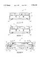
- FIG. 1is an isometric view of a notebook computer embodying this invention illustrating the screen folded down in a closed configuration in relation to the keyboard;
- FIG. 2is a plan view of the notebook computer of FIG. 1 illustrating the screen folded down in a closed configuration in relation to the keyboard;
- FIG. 3is a front elevational view of the notebook computer as depicted in FIG. 2;
- FIG. 4is a side elevational view of the notebook computer as depicted in FIG. 2;
- FIG. 5is a side elevational view of the notebook computer opposite to that depicted in FIG. 4;
- FIG. 6is a rear elevation view of the notebook computer as depicted in FIG. 2;
- FIG. 7is a plan view of the notebook computer of FIGS. 1-6 illustrating the screen opened in relation to the keyboard;
- FIG. 8is a front elevational view of the notebook computer as depicted in FIG. 7;
- FIG. 9is a partial breakaway view from the encircled region depicted in FIG. 8 illustrating attachment of the upper cover to the upper case;
- FIG. 10is an enlarged partial sectional view taken generally along line 10--10 of FIG. 8 illustrating attachment of the lower cover to the lower case;
- FIG. 11is an enlarged partial sectional view taken generally along line 11--11 of FIG. 7 illustrating attachment of the cover, trim panel and screen to the upper case;
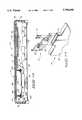
- FIG. 12is a vertical sectional view of the lower case taken generally along line 12--12 of FIG. 7;
- FIG. 13is a partial breakaway exploded isometric view depicting the pocketed mounting of the uppercase and hinge to a receptacle of the lower case;
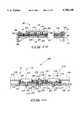
- FIG. 14is a vertical sectional view of the keyboard of the device taken generally along the line 14--14 of FIG. 7;
- FIG. 15is a vertical sectional view of the mouse assembly taken generally along the line 15--15 of FIG. 7.
- FIG. 1illustrates a portable personal computer namely a notebook computer 10 embodying this invention.
- the computerhas a housing 12 formed by a lower case 14 and an upper case 15.
- the upper caseis rotatably carried by the lower case through a pair of hinges 18.
- the upper casehouses a thin panel display 20 in rotatable relation with the lower case, as shown in FIG. 8, such that a user can move the display and case from a closed, or stowed position into a vertically rotated in-use position.
- FIGS. 7 and 8depict the computer in an opened, or in-use configuration wherein a keyboard 22 is also provided in a top surface, or face 24 of the lower case 14.
- FIGS. 1-6depict the same computer 10 in a closed, or slowed configuration.
- the lower case 14is formed by fastening together a top shell 26 and a bottom shell 28 (see FIG. 10). Likewise, a front shell 30 and a back shell 32 are fastened together to form the upper case 16 (see FIG. 11).
- threaded fastenersare used to assemble mating pairs of shells 26, 28 and 30, 32 together.
- shells 26-42are each formed from magnesium castings in order to provide a strong and rigid mounting structure for mounting the various internal components of the computer 10. Alternatively, aluminum or any of a number of other lightweight metal alloys could be utilized to form the structure.
- shells 26-32can be formed from lightweight composite materials including a resin and glass, carbon fiber, kevlar, or other enforcing fiber matrix construction.
- shells 30 and 32 of FIG. 11cooperate to form the upper case 16 which has side walls 34-37, back wall 38 and front wall 40 (see. FIGS. 1 and 7) configured in adjacent edge communication to define the upper case 16.
- shells 30 and 32 of FIG. 11cooperate to form lower case 14 which has side walls 42-45 (see FIG. 1), top wall 46 and bottom wall 48 which are configured in adjacent edge communication to form the lower case 14. Additional, resilient covering material encases portions of each case.
- each coveris made from an impact attenuating resilient elastomeric material such as SorbothaneTM which is a registered trademark of Sorbothane, Inc.
- SorbothaneTMwhich is a registered trademark of Sorbothane, Inc.
- various other forms of energy/absorbing or energy dissipating plastic or foam materialscan be utilized to form the covering.
- the coveringis necessarily provided on cases 14 and 16 in order to protect the housing 12 and the internal components of the computer 10 in the event of an impact with an exterior of the computer 10, either by dropping the computer, or striking the computer with another object.
- notebook computer 10houses a motherboard 54 within lower case 14.
- Motherboard 54is substantially formed by a printed circuit board on which a central processing unit (cpu) 56 and a plurality of memory modules 58 are mounted together in electrical interconnection.
- cpucentral processing unit
- motherboard 54is mounted directly to the inside of case 14, by securing, it to bosses 59 molded directly from top shell 26.
- a hard drive 60is also mounted to the inside of case 14.
- each coveris formed from a single piece of resilient plastic material having a hinge at a bottom edge and a resilient in-molded clip at a top edge.
- a telephone jack 66is also formed in the back wall 45 of the lower case 14 adjacent cover 64.
- a serial communication port 68 and a parallel communication port 70exit case 14 through back wall 45, from behind access cover 64.
- serial port 68is an RS 232 port.
- a PCMCIA slot 72is also formed in case 14, extending through back wall 45, and is hidden from view behind access cover 62 when not in use. Additionally, an on/off switch is provided to facilitate turning the computer on and off.
- a mobile telephone 76is also housed within bottom case 14 as shown in FIG. 12.
- An antenna 78 for telephone 76is similarly housed in top case 16 as shown in FIG. 8, beneath a rubber closure panel 79 provided in an access port 81.
- a modem 80is also provided as shown in FIG. 12.
- a speaker and microphone 82are mounted to the bottom wall 48 of case 14 in order to facilitate the transmission of audible input and output signals between a user and computer 10.
- the-speaker and microphone 82could-be utilized in combination with the telephone 76 to carry on telephone conversations.
- the speaker/microphone 82could be utilized in combination with software programs resident in computer 10 requiring interactive communication between a user and a computer (i.e. software implemented facsimile features or other programs requiring audible communication between the user and the computer).
- FIG. 10depicts a battery tray 84 formed in bottom case 14 by an in-molded mount provided within the bottom shell 2S.
- a plurality of blade contacts 86extend vertically upward from tray 84 for mating in assembly with a battery (not shown) received within the tray.
- Blade contacts 86are desirable because they tend to maintain a spring-biased electrical contact between the battery terminals and blades, even when they are subjected to jarring, as might occur during impacts or sudden accelerations to the case.
- FIGS. 1-8illustrate the overall relative layout and construction of housing 12 formed by joining together bottom case 14 and top case 16.
- Cases 14 and 16are covered with impact attenuating coverings 52 and 50, respectively, which protect the rigid load-bearing structural components of each case formed by shells 26, 28 and 30, 32, respectively.
- coverings 50 and 52are each formed from an impact attenuating resilient elastomeric material as previously discussed hereinabove. The coverings overlay the respective cases in cooperative relation so as to effectively form a bumper encasing the housing components, or shells of the computer housing.
- each coveringin order to cover the portions of each case that will most likely, be subjected to impacts from either dropping the computer, or hitting the computer with an object such as a foot or a heavy object. Therefore, each corner of the computer is completely covered by the covering. Furthermore, the highest projecting regions on each exterior wall or outermost surface of the computer has covering material thereover. Therefore, if the computer is dropped onto a corner, the covering will protect the rigid magnesium shell components and internal computer hardware by shock-isolating the impact and attenuating its transmission there through into the internal components of the computer. Similarly, if the computer is dropped onto the ground on any one of the faces, the covering material will isolate the rigid magnesium shell components on the computer from direct contact with the ground.
- covering 50comes into direct contact with lower case 14 which prevents direct-abutting rigid contact between the hard magnesium components of each case. Therefore, covering 50 further isolates cases 14 and 16 from one another and attenuates shock transmission therebetween in the event the computer is dropped while in a folded configuration.
- Top case 16is also protected from impact damage by the particular construction and attachment features depicted in FIG. 8-9 and 11.
- Covering 50is fastened along the outer peripheral surfaces formed by shells 30 and 32 of upper case 16. In this configuration, the covering substantially extends about the outer periphery of the upper case so is to isolate the outer peripheral surface from direct impact with objects.
- both an inner and an outer row of tenons 88 and 90are formed on front wall 40 of shell 30, adjacent a peripheral edge portion of case 16, which together ensure retention of top covering 50 to upper use 16 during normal use.
- Each row of tenonsforms a discrete bead lip about the outer peripheral portion of the front screen wall 40, along the region where the cover attaches to the case.
- an inner surface 92 of the coveringengages with the peripheral outer face of case 16 formed by shells 30 and 32; namely, along the side wall regions 34-37. However, region 37 is separated into two discrete portions, each adjacent to where a hinge 18 is mated with lower case 14 (see FIG. 1).
- covering 50encases both portions forming region 37, and encircles a collar region 94 (see FIG. 6) formed by shells 30 and 32 where each hinge 18 extends therethrough.
- the coveringhas molded-in through ports 96 through which the hinges are inserted along with shells 30 and 32 during assembly.
- covering 50wraps around the back wall 38 of shell 32 where it forms a recessed lip-edge 98 as shown in FIG. 11.
- Lip-edge 98conformably cooperates with shell 32 to partially entrap covering 50 to shell 32 of case 16.
- the opposite edge of covering 50has an engaging lip 100 along the inner surface 92 of the covering which terminates in a lip-edge 102, forming a first and a second engaging trench 104 and 106, respectively.
- the first engaging trench 104forms a continuous groove which mates in assembly with the inner row of tenons 88 (see FIG.
- the second engaging trench 106consists of a plurality of in-molded mortises 107 discretely arranged in alignment to communicate in interdigitating engagement with the outer row of tenons 90 (see FIG. 9).
- tenons 88align within trench groove 104 which substantially seals along front wall 40 of computer, and outer tenons 90 discretely engage with each mortise 107 forming engaging trench 106.
- bottom covering 52is retained along the outer periphery of shells 26 and 28 in a manner similar to that used to retain cover 50 along top case 16.
- Bottom covering 52is preferably formed from impact attenuating resilient elastomeric material configured in the shape of a peripheral outer wall member. More particularly, covering member 52 of FIG. 10 has an inner face 108 which mates in assembly with an outer periphery of shells 26 and 28 forming the bottom case 14; namely, side walls 42-45 (see FIG. 1). Outer face 110 substantially forms the visible outer periphery of bottom case 14 including side walls 42-45 (see FIG. 1).
- a top edge 112 and a bottom edge 114 of covering 52form engaging lips 116 and 118, respectively, as shown in FIG. 10.
- Each lip 116 and 118forms an in-turned lip-edge 120 and 122, respectively.
- Each lip-edge 120 and 122defines a corresponding engaging trench 124 and 126, respectively.
- Trenches 124 and 126each form a row of mortises 128 which mate with an array of complementary-corresponding tenons 130 configured along the outer periphery of lower case 14.
- Tenons 130are arranged in two groups along the peripheral outer wall of the lower case.
- An upturned lip-edge 132forms a plurality of tenons and a downturned lip-edge 134 forms a corresponding array of tenons.
- covering 52To assemble covering 52 to the outer periphery of case 14, lip-edge 120 and engaging trench 124 are first snapped over tenons 130 on lip-edge 132. Subsequently, covering member 52 is resiliently flexed so as to peel bottom lip-edge 122 and trench 126 over the corresponding downturned lip-edge 134 on use 14. In this manner, covering 52 can be engaged about each of the bottom case side walls 42-45 (see FIG. 1) in an interlocked manner.
- covering 52merely extends part way beyond the corners to form a partial covering of back wall 45 adjacent side walls 42 and 44 so as to facilitate access to input/output ports and jacks 66-72, generally, provided in the back of computer 10.
- end portions 136 and 138are formed by covering 52 where it encases back wall 45.
- each end portionis subsequently retained to back wall 45 preferably with a plastic rivet 140.
- the ends of assembled covering 52can be retained to prevent any tendency of the covering to un-zip from edges 132 and 134 of shells 26 and 28 (see FIG. 10) forming case 14.
- each foot 142is formed by in-molding the foot at each of the corners along the bottom edge 114 (see FIG. 10) of cover 52 such that a semi-rectangular piece of under-tapping elastomeric material extends underneath the case when configured in the assembled state.
- a fastener hole 144is provided through each foot such that a fastener further secures covering 52 at each corner to bottom wall 48 of case 14.
- inner face 108 of covering 52contains a plurality of vertically extending parallel cavities 146 as shown in FIG. 10.
- Each cavity 146has a semi-circular cross-sectional configuration, the cavities cooperating to form an array of semi-cylindrical vertically extending adjacent cavities 146.
- the cavitiescooperate to facilitate flexing of cover 52 during assembly to case 14, and additionally define fingers 148 interposed between each pair of cavities that cooperate with the outer periphery of the case to enhance energy absorption of the covering resulting from any impacts supplied to the exterior of the covering acting against the case.
- cavities 146are provided substantially along the entire vertical height of walls 42-44 (see FIG. 1), with the exception of the adjacent top and bottom edges formed therealong. In this manner, cavities 146 effectively soften the padding-effect of the covering along the straight portions of each side wall.
- each corner regionresults in a stronger and stiffer padding at each respective corner portion.
- Such a constructionis desirable since impacts that occur with the corners of case 14 typically result in a substantially decreased contact surface area due to the sharp protruding geometry of the case in these regions. As a consequence, a given amount of impact force must be distributed over a much reduced surface area of impact, resulting in much higher local forces in the padding, which increases the stresses being transferred to the material.
- each cavity 146terminates before the top and bottom edges 112 and 114, such that the top and bottom edges are also imparted with a solid covering or padding having a much higher stiffness with respect to the cavitied side walls.
- a trim cover 150is also mounted to the back wall 38 of top case 16 to complete the packaging of the upper case 16.
- Cover 150is preferably molded from a rigid or semi-rigid plastic material having a desired color that matches the color scheme of the computer.
- a plurality of in-molded slotted receivers 152are formed on a bottom side of cover 150 to allow for mounting of the cover to back shell 32 of case 16
- cover 150when fastened to case 16, has an exterior surface slightly recessed from the top most surface formed by resilient covering 50.
- the recessed lip-edge 98 on covering 50supports cover 150 along its outermost edges. As shown in FIG.
- a pair of ears 154rearwardly extend from cover 150 in order to finish the trim of top case 16 along collar regions 94.
- a plurality of spring clips 156are mounted to shell 32 along back wall 38 with fasteners 158, as shown in FIG. 11, wherein each spring clip is provided in a location that mates with a complementary corresponding slotted receiver 152 on the back of cover 150.
- cover 150 during assemblycan be flexed in order to engage each of the spring clips into each of the slotted receivers which forcibly engages the bottom peripheral edge of the cover with the covering recess lip-edge 98 so as to retain cover 150 to the-lip-edge in positively-biased engagement therebetween.
- each ear 154(see FIG. 2) is also slightly recessed with respect to covering 50 when mated together in a final assembled configuration.
- FIG. 13illustrates a pocketed mounting construction for securely retaining upper case 16 and hinge 18 to lower case 14. More particularly, as shown in partial breakaway exploded isometric view from the rear, hinge 18 is mounted to an inside face of front shell 30, then pocketed, or received in a receptacle, or mounting well 55 of top shell 26 where it is secured with threaded fasteners 57.
- a frictionally engaging mounting configurationis utilized to return thin panel display 20 in sandwiched engagement between the front and back shells 30 and 32 forming upper case 16.
- a display opening 160is defined in front wall 40 of case 16 which turns inwardly along the opening to form a bezel 162 having an in-turned lip 164.
- a circumferentially extending seal 166 and 168extends adjacent the outer peripheral of display 20, on either side, such what seal 166 mates between the screen and inner fact of shell 32 and seal 168 males between display 20 and the in-turned lip 164 of shell 30.
- display 20is inserted between shells 30 and 32, after which shells 30 and 32 are joined together by threaded fasteners (not shown) which draw them together into engagement such that seals 166 and 168, which are sized to forcibly engage with display 20, resiliently retain screen display 20 therebetween.
- the resulting constructionfrictionally engages screen display 20 between shells 30 and 32, yet allows for dissipation of impact-induced shock waves travelling through shells 30 and 32 which might otherwise travel from case 16 into screen 20. Therefore, a shock-isolated screen mount is provided within upper case 16.
- keyboard assembly 22is retained to keyboard mounting face 24 where it is sealed in engagement therewith.
- Keyboard assembly 22is preferably formed by a plastic key tray 170 in which a plurality of keys 172 are supported in axially moveable relation, a contiguous sheet of water impervious resilient elastomeric material 174, and a keyboard circuit board 176.
- Key tray 170, sheet of material 174, and circuit board 176are preferably fastened together as a subassembly wherein the subassembly is seated on mounting face 24 formed by the top of shell 26 (see FIG. 10) of lower case 14.
- a keyboard bezel 180is then secured to face 24 with threaded fasteners, which retains the keyboard subassembly against the face where it mates in sealing engagement therewith.
- the sheet of material 174is preferably formed from a silicon synthetic rubber material which enables it to seal in engagement with keyboard mounting face 24.
- a T-shaped. peripheral edge 184is preferably formed along the entire outer peripheral edge portion of sheet 174, wherein one leg of T-shaped edge 184 provides a peripheral top face 186 that mates in engagement with bezel 180 during assembly and a peripheral bottom face 188 that seals in engagement with mounting face 24.
- an L-shaped edgecan be provided such that a resulting leg extends downwardly into engagement with mounting face 24.
- Peripheral top face 186defines a well on the top of the sheet in which key tray 170 is received in final assembly.
- peripheral bottom face 188forms a well into which keyboard circuit board 176 is received in assembly.
- the maximum thickness of circuit board 176is less than the depth of bottom face 188 which ensures forcible retention and sealing of bottom face 188 with mounting face 24 formed by the case.
- bottom face 188forms a face portion that seals in engagement with mounting face 24 when bezel 180 is fastened downwardly against the top of the case.
- bezel 180provides a retainer including an engaging face portion 192 that seats in engagement with top face 186 of sheet 174 when arranged in an assembled configuration. As shown in FIG. 14, engaging face portion 192 is formed beneath an inner lip-edge 194 extending about the entire inner circumference of bezel 180. Additionally, mounting holes (not shown) are provided in bezel 180 for receiving threaded fasteners which forcibly engage bezel 180 against sheet, 174 and case mounting face 24. The fasteners provide a means for forcibly engaging bezel 180 with sheet 174 in sealing engagement with mounting face 24 entirely circumferentially thereabout.
- circuit board 176is provided with fastener through-holes 196 in alignment with through-holes 200 formed in sheet of material 174 and internally-threaded bosses 201 formed on the bottom of key tray 170.
- An encircling rib 204is integrally formed in sheet of material 174 about each through-hole 200 such that, when a fastener 206 is received through the corresponding holes in the circuit board, sheet of material, and the threaded bosses of the key tray, the encircling ribs 204, of sheet 174 seal in engagement with the ends of the bosses 202 as well as the bottom of key tray 170. As a result, any water that would otherwise migrate past keys 172 and through key tray 170 is prevented from leaking through through-holes 200 formed in the sealing sheet 174.
- the sheet of membrane material 174has a plurality of in-molded raised dimples 207 that are formed beneath each key 172 and directly above a key circuit element 209 formed on the circuit keyboard 176 beneath each key 172.
- raised dimple 207preferably functions as a spring that ensures biasing apart of key 172 from circuit element 209 when in a relaxed state.
- dimple 207is compressed which brings key 172 in close proximity to key circuit element 209 where its motion is detected by one of several readily known techniques.
- One technique for detecting a depressed condition of a keyutilizes a capacitive key wherein the key circuit element forms two spaced apart metallic areas and the key end has a plated pad formed from a material such as tin, nickel, or copper such that when the key end is brought in close proximity to the circuit element, a capacitive change is noted by the circuit board and a key-depressed state is acknowledged by a corresponding keyboard microprocessor and logic unit.
- An alternative constructionincorporates a hard-contact keyboard, wherein the key has a stem that directly engages with the depressed dimple in close proximity with a pair of contacts comprising the circuit element which are then brought into electrically-communicative relationship therebetween.
- a plurality of breather holes 205are preferably formed in both circuit board 176 and mounting face 24 in order to prevent trapping of air beneath each dimple 207 which might result in locally sealed and pressurized dimples that could affect the touch-and-feel of the dimples and keys as they are depressed by a user.
- a cursor control device 208otherwise known as a tactile input device, preferably in the form of a pointing stick, is also provided in sealed engagement with mounting face 24 of lower case 14 adjacent to the front edge of keyboard assembly 22.
- Tactile input device 208includes a weather sealed covering 210 consisting of a skirt 212 molded from resilient elastomeric material, a wand casing 214, and a pair of button casing 216 and 218 which are in-place molded during formation of skirt 212.
- Skin 212forms a local depression 213, 215, and 217 about each of casings 214, 216, and 218, respectively.
- molded skirt 212is formed from a synthetic rubber material.
- casings 214-218are completely sealed with skirt 212.
- wand casing 214is formed centrally in the skirt and the pair of button casings 216 and 218 are formed bilaterally of wand casing 214.
- each button casing 216 and 218has a downwardly extending stem 220 that extends through a hole 221 and 223 respectively, formed within mounting face 24.
- a central hole 224is also formed for wand casing 214 wherein a mouse wand 226 extends up through hole 224 where it mates within a recess 228 in the bottom of wand casing 214.
- each gasket face 230-232is integrally formed on mounting face 24 such that each gasket face is aligned to mare with a thickened encircling rib 234-236 formed about wand casing 214 and button casings 216 and 218, respectively.
- Each encircling rib 234-236is formed by a thickened portion of skirt 212 such that a top most portion of the encircling rib 234-236 is forcibly engaged by a corresponding engagement face 238-240, respectively, formed about openings 242-244 in bezel 180.
- the fasteners used to forcibly engage bezel 180 when sealing keyboard assembly 22also forcibly engage faces 238-240 with encircling ribs 234-236, respectively, which forcibly and sealingly engages each gasket face 230-232 within a complementary corresponding sealing groove 246-248, respectively, provided in an encircling manner about each wand casing 214 and button casings 216 and 218, respectively.
- Wand casing 214in cooperation with mouse wand 226 produces a finger engagable wand which is user operable from the exterior of the computer, yet seals mouse wand 226 from fluid contaminants entering therein. Additionally, each button casing 216 and 218 engages through a dedicated button stem 220 with a clicker button 250 and 251 mounted within bottom case 14.
- an isolation mount assemblyis utilized to support the hard drive inside the lower case 14. More particularly, as shown in FIG. 12 four different bosses 252 are integrally formed from top shell 26 to which a mounting bridge 254 that supports the hard drive 60 is retained. Four corresponding mounting apertures 256 are formed in the mounting bridge. A grommet 258 having a receiving groove 260 formed on its outer periphery seats within the aperture and a fastener receiving hole 262 is provided through the grommet. Subsequently, a threaded fastener 264 having an expanded head with a washer is received through the grommet and aperture of bridge 254 into a correspondingly threaded bore 266 in each boss 252. As a result, mounting bridge 254 is retained in shock-isolated and suspended engagement with each of bosses 252, and hard drive 60 is retained to a portion of bridge 254 with threaded fasteners (not shown).
- mounting bridge 254is formed from a lightweight piece of aluminum. Additionally, bridge 254 is preferably sized with a thickness and width chat imparts a tuned bending stiffness in relation to the mass of hard drive 60 such that shock-induced vibrations input to housing 12 (see FIG. 1) from externally applied impacts minimize local accelerations of the hard drive caused by the bending of the bridge in response to forces created from the mass of hard drive 60 as it is subjected to accelerations and decelerations.
- a hard drive 60 having an outer diameter of 1.8 inchesis preferably utilized since a hard drive of this construction generally has a smaller mass than alternatively available hard drives.
- a hard drive of this constructiongenerally has a smaller mass than alternatively available hard drives.
Landscapes
- Engineering & Computer Science (AREA)
- Computer Hardware Design (AREA)
- Theoretical Computer Science (AREA)
- Physics & Mathematics (AREA)
- General Engineering & Computer Science (AREA)
- Human Computer Interaction (AREA)
- General Physics & Mathematics (AREA)
- Mathematical Physics (AREA)
- Casings For Electric Apparatus (AREA)
Abstract
Description
Claims (14)
Priority Applications (2)
| Application Number | Priority Date | Filing Date | Title |
|---|---|---|---|
| US08/499,488US5706168A (en) | 1995-07-07 | 1995-07-07 | Impact-resistant notebook computer having hard drive mounted on shock-isolating mounting bridge and impact attenuating covering |
| US08/693,511US5697718A (en) | 1995-07-07 | 1996-08-02 | Weather sealed keyboard assembly for portable personal computers |
Applications Claiming Priority (1)
| Application Number | Priority Date | Filing Date | Title |
|---|---|---|---|
| US08/499,488US5706168A (en) | 1995-07-07 | 1995-07-07 | Impact-resistant notebook computer having hard drive mounted on shock-isolating mounting bridge and impact attenuating covering |
Related Child Applications (1)
| Application Number | Title | Priority Date | Filing Date |
|---|---|---|---|
| US08/693,511DivisionUS5697718A (en) | 1995-07-07 | 1996-08-02 | Weather sealed keyboard assembly for portable personal computers |
Publications (1)
| Publication Number | Publication Date |
|---|---|
| US5706168Atrue US5706168A (en) | 1998-01-06 |
Family
ID=23985454
Family Applications (2)
| Application Number | Title | Priority Date | Filing Date |
|---|---|---|---|
| US08/499,488Expired - LifetimeUS5706168A (en) | 1995-07-07 | 1995-07-07 | Impact-resistant notebook computer having hard drive mounted on shock-isolating mounting bridge and impact attenuating covering |
| US08/693,511Expired - LifetimeUS5697718A (en) | 1995-07-07 | 1996-08-02 | Weather sealed keyboard assembly for portable personal computers |
Family Applications After (1)
| Application Number | Title | Priority Date | Filing Date |
|---|---|---|---|
| US08/693,511Expired - LifetimeUS5697718A (en) | 1995-07-07 | 1996-08-02 | Weather sealed keyboard assembly for portable personal computers |
Country Status (1)
| Country | Link |
|---|---|
| US (2) | US5706168A (en) |
Cited By (49)
| Publication number | Priority date | Publication date | Assignee | Title |
|---|---|---|---|---|
| GB2341439A (en)* | 1998-09-14 | 2000-03-15 | Penny & Giles Computer Product | Manual control device with sealed components, eg a sterilisable trackerball |
| US6151207A (en)* | 1997-11-28 | 2000-11-21 | Samsung Electronics Co., Ltd. | Structure for protecting electronic systems from impact and portable computer with such a structure |
| US6166901A (en)* | 1998-03-13 | 2000-12-26 | International Business Machines Corporation | Vibration dampening system for removable hard disk drive carriers |
| US6262888B1 (en) | 1999-06-30 | 2001-07-17 | Dell Usa, L.P. | Impact damping system for peripheral device |
| US6310769B1 (en) | 2000-05-03 | 2001-10-30 | Dell Products L.P. | Mounting bracket assembly for system components in a computer |
| US6353531B1 (en) | 1999-08-25 | 2002-03-05 | Dell Usa, L.P. | Integrated visor for a notebook computer |
| US20020184803A1 (en)* | 2001-04-20 | 2002-12-12 | Gerhard Kaiser | Inscription method for an electrical appliance |
| US6498719B1 (en) | 1999-12-10 | 2002-12-24 | Dell Usa, L.P. | Apparatus and method for reducing impact-induced shock and vibration in a portable computer |
| US20030002246A1 (en)* | 2001-06-15 | 2003-01-02 | Apple Computers, Inc. | Active enclousure for computing device |
| US6522763B2 (en) | 1998-08-13 | 2003-02-18 | International Business Machines Corporation | Impact-resistant electronic device |
| US20030034904A1 (en)* | 2001-08-14 | 2003-02-20 | Deluga Ronald E. | Spill-resistant keyboard |
| US20030058611A1 (en)* | 2001-09-26 | 2003-03-27 | Lg Electronics Inc. | Computer with built-in type speakers |
| US6580606B1 (en) | 2000-09-25 | 2003-06-17 | Micron Technology, Inc. | Modular drive cage assembly |
| US6586058B1 (en)* | 1997-01-13 | 2003-07-01 | International Business Machines Corporation | Equipment packages for shock resistance |
| US20030156382A1 (en)* | 2001-12-26 | 2003-08-21 | Sony Corporation | Electronic device |
| US20030179544A1 (en)* | 2002-03-20 | 2003-09-25 | Bruner Curtis H. | Digital storage element mechanical shock isolation arrangement in a host device and method |
| US6662425B2 (en)* | 2000-04-28 | 2003-12-16 | Hong-Line Chern | Combination mobile computer metal shell fabrication method |
| US20040022014A1 (en)* | 2002-07-31 | 2004-02-05 | Dell Products, L.P. | Method of preventing LCD damage in an information handling system |
| US20040034724A1 (en)* | 2001-09-14 | 2004-02-19 | Bruner Curtis H. | Digital device configuration and method |
| EP1233434A3 (en)* | 2001-02-14 | 2004-06-16 | Whirlpool Corporation | Pushbutton structure for electronic, electrical and/or mechanical appalications |
| US6791799B2 (en) | 2001-09-14 | 2004-09-14 | Convergent Systems Solutions Llc | Digital device configuration and method |
| US20050024820A1 (en)* | 2003-07-29 | 2005-02-03 | Yu Chen | Casing structure of a portable electronic device |
| US20050094358A1 (en)* | 2003-10-21 | 2005-05-05 | Kiyoshi Shirato | Information processing apparatus |
| US20050130470A1 (en)* | 2003-11-28 | 2005-06-16 | Tetsuya Kugimiya | Mobile electronic appliance |
| US20050154823A1 (en)* | 2001-09-14 | 2005-07-14 | Bruner Curtis H. | Digital device configuration and method |
| US20050182875A1 (en)* | 2001-09-14 | 2005-08-18 | Bruner Curtis H. | Digital device configuration and method |
| US20050270244A1 (en)* | 1999-05-14 | 2005-12-08 | Apple Computer, Inc. | Display housing for computing device |
| US7059182B1 (en)* | 2004-03-03 | 2006-06-13 | Gary Dean Ragner | Active impact protection system |
| US20060152892A1 (en)* | 2004-12-21 | 2006-07-13 | Yasuo Matsumoto | Apparatus for improving durability of electronic devices |
| US7113196B2 (en) | 2001-06-15 | 2006-09-26 | Apple Computer, Inc. | Computing device with dynamic ornamental appearance |
| US20060256037A1 (en)* | 2001-06-15 | 2006-11-16 | Apple Computer, Inc. | Active enclosure for computing device |
| US20060261528A1 (en)* | 2005-05-23 | 2006-11-23 | Seagate Technology Llc | Shock absorber for a storage system |
| US20070041149A1 (en)* | 2005-08-22 | 2007-02-22 | Homer Steven S | Computer device with stiffened display member |
| US20070199804A1 (en)* | 2006-02-27 | 2007-08-30 | Cherry Corporation | Two part cleanable keyboard |
| US20080024965A1 (en)* | 2006-03-31 | 2008-01-31 | Matsushita Electric Industrial Co., Ltd. | Portable information processor, housing of portable information processor, and method for manufacturing the housing |
| US7443388B1 (en) | 1999-05-14 | 2008-10-28 | Apple Inc. | Housing for a computing device |
| WO2009140690A2 (en) | 2008-05-16 | 2009-11-19 | Eric William Brader | Ultrasound device and system including same |
| US20090289571A1 (en)* | 2001-06-15 | 2009-11-26 | Apple Inc. | Active enclosure for computing device |
| US20100008027A1 (en)* | 2008-07-08 | 2010-01-14 | Hong Fu Jin Precision Industry (Shenzhen) Co., Ltd. | Portable apparatus and positioning device thereof |
| US20100316229A1 (en)* | 2009-06-10 | 2010-12-16 | David Bibl | Electronic device accessories formed from intertwined fibers |
| US20110001280A1 (en)* | 2009-07-03 | 2011-01-06 | Multi-Expander Technology Inc. | Shock absorber and shock absorbing structure for absorbing vibration of an article |
| US20110236726A1 (en)* | 2010-03-29 | 2011-09-29 | Ha Jae-Young | Battery pack |
| US20120044155A1 (en)* | 2010-08-23 | 2012-02-23 | Lenovo (Singapore) Pte. Ltd. | Convertible pc having a waterproofing structure |
| US8411432B1 (en)* | 2009-12-02 | 2013-04-02 | Dell Products, Lp | System, apparatus and method for tiered shock solution |
| US20140211386A1 (en)* | 2011-09-15 | 2014-07-31 | Hewlett-Packard Development Company, L.P. | Computer devices and methods of preventing damage to a display |
| US9130265B1 (en)* | 2007-08-28 | 2015-09-08 | Apple Inc. | Electronic device with conductive housing and near field antenna |
| WO2018080841A1 (en)* | 2016-10-26 | 2018-05-03 | Urban Armor Gear, Llc | Protective case for a computing device |
| CN109989336A (en)* | 2019-04-26 | 2019-07-09 | 重庆大学 | A wind-resistant and shock-absorbing bridge hanger using magnetic levitation technology for vibration isolation |
| US10884453B2 (en) | 2015-10-09 | 2021-01-05 | Urban Armor Gear, Llc | Protective case for a computing device and method of use |
Families Citing this family (21)
| Publication number | Priority date | Publication date | Assignee | Title |
|---|---|---|---|---|
| DE19626626C2 (en)* | 1996-07-02 | 2000-08-03 | Cherry Mikroschalter Gmbh | Splashproof keyboard |
| US6040823A (en)* | 1997-12-02 | 2000-03-21 | Cts | Computer keyboard having top molded housing with rigid pointing stick integral and normal to front surface of housing as one unit part to be used with strain sensors in navigational control |
| JPH11316647A (en)* | 1998-05-01 | 1999-11-16 | Nec Yonezawa Ltd | Computer system |
| TW371501U (en)* | 1998-07-07 | 1999-10-01 | Acer Comm & Multimedia Inc | Keyboard structure |
| TW385891U (en) | 1998-07-07 | 2000-03-21 | Acer Peripherals Inc | Water-proof keyboard |
| JP2000215754A (en) | 1999-01-26 | 2000-08-04 | Nec Shizuoka Ltd | Operating button structure for electronic equipment |
| US6307739B1 (en)* | 1999-05-18 | 2001-10-23 | Micron Technology, Inc. | Computer system form factor |
| CA2442032A1 (en)* | 2001-03-28 | 2002-10-10 | Barbara Sexton | Computer |
| US6853366B2 (en)* | 2002-10-11 | 2005-02-08 | James H. Bowen | Articulator and optical detection cursor positioning device |
| US6705783B1 (en) | 2002-10-11 | 2004-03-16 | James H. Bowen | Ruggedized keyboard with cursor positioning device |
| US6970347B2 (en)* | 2003-08-25 | 2005-11-29 | Dell Products L.P. | Method and system for tooless keyboard assembly into an information handling system housing |
| US7850378B1 (en)* | 2005-05-13 | 2010-12-14 | Apple Inc. | Webbed keyboard assembly |
| JP4703308B2 (en)* | 2005-07-29 | 2011-06-15 | 株式会社東芝 | Electronics |
| TWI320900B (en)* | 2006-01-18 | 2010-02-21 | Darfon Electronics Corp | Key operated apparatus having shield and method of making the same |
| US20070235370A1 (en)* | 2006-03-31 | 2007-10-11 | Anthony Reale | Protective chassis cover system and method |
| US8500348B2 (en)* | 2008-11-24 | 2013-08-06 | Logitech Europe S.A. | Keyboard with ultra-durable keys |
| GB2516810A (en)* | 2013-06-06 | 2015-02-11 | Dale Mcphee Purcocks | A method of manufacturing a key plate for an electronic keyboard |
| US9098250B2 (en)* | 2013-07-17 | 2015-08-04 | Lenovo (Singapore) Pte. Ltd. | Computer assembly incorporating coupling within pantograph |
| US11099610B1 (en)* | 2020-06-02 | 2021-08-24 | Getac Technology Corporation | Mobile electronic device |
| TWI747700B (en)* | 2021-01-06 | 2021-11-21 | 致伸科技股份有限公司 | Keyboard |
| US11899849B1 (en)* | 2022-11-02 | 2024-02-13 | Finalmouse LLC | Computer keyboard with a display |
Citations (7)
| Publication number | Priority date | Publication date | Assignee | Title |
|---|---|---|---|---|
| US4571456A (en)* | 1982-10-18 | 1986-02-18 | Grid Systems Corporation | Portable computer |
| US4703161A (en)* | 1986-09-30 | 1987-10-27 | Mclean Roger D | Ruggedized calculator |
| WO1989004057A1 (en)* | 1987-10-20 | 1989-05-05 | Bell Communications Research, Inc. | Epitaxial intermetallic contact for compound semiconductors |
| US5195022A (en)* | 1991-11-01 | 1993-03-16 | Hewlett-Packard Company | Removable mass storage module for computer systems |
| US5220520A (en)* | 1990-01-31 | 1993-06-15 | Kabushiki Kaisha Toshiba | Compact portable electronic apparatus capable of storing data when a power supply is removed |
| US5239444A (en)* | 1989-10-20 | 1993-08-24 | Kabushiki Kaisha Toshiba | Tiltable portable electronic apparatus with sliding tilt leg |
| US5351176A (en)* | 1992-12-31 | 1994-09-27 | North Atlantic Industries, Inc. | Panel for a computer including a hinged door with integral display |
Family Cites Families (5)
| Publication number | Priority date | Publication date | Assignee | Title |
|---|---|---|---|---|
| US3890480A (en)* | 1974-05-23 | 1975-06-17 | Cincinnati Milacron Inc | Hermetic sealing structure for electronic keyboard apparatus |
| US4322587A (en)* | 1979-12-06 | 1982-03-30 | Rogers Corporation | Keyboard device |
| US4791258A (en)* | 1987-07-31 | 1988-12-13 | Hamilton Standard Controls, Inc. | Sealed enclosure for electrical circuitry in moist environment |
| DE3739142A1 (en)* | 1987-11-19 | 1989-06-01 | Freudenberg Carl Fa | Keyboard |
| DE69133364T2 (en)* | 1990-10-30 | 2004-12-09 | Teikoku Tsushin Kogyo Co. Ltd., Kawasaki | Method of making a button |
- 1995
- 1995-07-07USUS08/499,488patent/US5706168A/ennot_activeExpired - Lifetime
- 1996
- 1996-08-02USUS08/693,511patent/US5697718A/ennot_activeExpired - Lifetime
Patent Citations (8)
| Publication number | Priority date | Publication date | Assignee | Title |
|---|---|---|---|---|
| US4571456A (en)* | 1982-10-18 | 1986-02-18 | Grid Systems Corporation | Portable computer |
| US4571456B1 (en)* | 1982-10-18 | 1995-08-15 | Grid Systems Corp | Portable computer |
| US4703161A (en)* | 1986-09-30 | 1987-10-27 | Mclean Roger D | Ruggedized calculator |
| WO1989004057A1 (en)* | 1987-10-20 | 1989-05-05 | Bell Communications Research, Inc. | Epitaxial intermetallic contact for compound semiconductors |
| US5239444A (en)* | 1989-10-20 | 1993-08-24 | Kabushiki Kaisha Toshiba | Tiltable portable electronic apparatus with sliding tilt leg |
| US5220520A (en)* | 1990-01-31 | 1993-06-15 | Kabushiki Kaisha Toshiba | Compact portable electronic apparatus capable of storing data when a power supply is removed |
| US5195022A (en)* | 1991-11-01 | 1993-03-16 | Hewlett-Packard Company | Removable mass storage module for computer systems |
| US5351176A (en)* | 1992-12-31 | 1994-09-27 | North Atlantic Industries, Inc. | Panel for a computer including a hinged door with integral display |
Cited By (124)
| Publication number | Priority date | Publication date | Assignee | Title |
|---|---|---|---|---|
| US6586058B1 (en)* | 1997-01-13 | 2003-07-01 | International Business Machines Corporation | Equipment packages for shock resistance |
| US6151207A (en)* | 1997-11-28 | 2000-11-21 | Samsung Electronics Co., Ltd. | Structure for protecting electronic systems from impact and portable computer with such a structure |
| US6166901A (en)* | 1998-03-13 | 2000-12-26 | International Business Machines Corporation | Vibration dampening system for removable hard disk drive carriers |
| US6522763B2 (en) | 1998-08-13 | 2003-02-18 | International Business Machines Corporation | Impact-resistant electronic device |
| GB2341439A (en)* | 1998-09-14 | 2000-03-15 | Penny & Giles Computer Product | Manual control device with sealed components, eg a sterilisable trackerball |
| GB2341439B (en)* | 1998-09-14 | 2003-02-12 | Penny & Giles Comp Products | Control device |
| US20050270244A1 (en)* | 1999-05-14 | 2005-12-08 | Apple Computer, Inc. | Display housing for computing device |
| US7440264B2 (en) | 1999-05-14 | 2008-10-21 | Apple Inc. | Display housing for computing device |
| US6977808B2 (en)* | 1999-05-14 | 2005-12-20 | Apple Computer, Inc. | Display housing for computing device |
| US20090009947A1 (en)* | 1999-05-14 | 2009-01-08 | Apple Inc. | Display housing for computing device |
| US8139349B2 (en) | 1999-05-14 | 2012-03-20 | Apple Inc. | Display housing for computing device |
| US20050270734A1 (en)* | 1999-05-14 | 2005-12-08 | Apple Computer, Inc. | Display housing for computing device |
| US7679893B2 (en) | 1999-05-14 | 2010-03-16 | Apple Inc. | Display housing for computing device |
| US8256913B2 (en) | 1999-05-14 | 2012-09-04 | Apple Inc. | Housing for a computing device |
| US20090257232A1 (en)* | 1999-05-14 | 2009-10-15 | Apple Inc. | Display housing for computing device |
| US7724509B2 (en) | 1999-05-14 | 2010-05-25 | Apple Inc. | Display housing for computing device |
| US7443388B1 (en) | 1999-05-14 | 2008-10-28 | Apple Inc. | Housing for a computing device |
| US7460362B2 (en) | 1999-05-14 | 2008-12-02 | Apple Inc. | Display housing for computing device |
| US6262888B1 (en) | 1999-06-30 | 2001-07-17 | Dell Usa, L.P. | Impact damping system for peripheral device |
| US6353531B1 (en) | 1999-08-25 | 2002-03-05 | Dell Usa, L.P. | Integrated visor for a notebook computer |
| US6498719B1 (en) | 1999-12-10 | 2002-12-24 | Dell Usa, L.P. | Apparatus and method for reducing impact-induced shock and vibration in a portable computer |
| US6662425B2 (en)* | 2000-04-28 | 2003-12-16 | Hong-Line Chern | Combination mobile computer metal shell fabrication method |
| US6310769B1 (en) | 2000-05-03 | 2001-10-30 | Dell Products L.P. | Mounting bracket assembly for system components in a computer |
| US6580606B1 (en) | 2000-09-25 | 2003-06-17 | Micron Technology, Inc. | Modular drive cage assembly |
| EP1233434A3 (en)* | 2001-02-14 | 2004-06-16 | Whirlpool Corporation | Pushbutton structure for electronic, electrical and/or mechanical appalications |
| US20020184803A1 (en)* | 2001-04-20 | 2002-12-12 | Gerhard Kaiser | Inscription method for an electrical appliance |
| US20090289571A1 (en)* | 2001-06-15 | 2009-11-26 | Apple Inc. | Active enclosure for computing device |
| US20090040748A1 (en)* | 2001-06-15 | 2009-02-12 | Apple Inc. | Active enclosure for computing device |
| US7766517B2 (en) | 2001-06-15 | 2010-08-03 | Apple Inc. | Active enclosure for computing device |
| US7728799B2 (en) | 2001-06-15 | 2010-06-01 | Apple Inc. | Active enclosure for computing device |
| US7868905B2 (en) | 2001-06-15 | 2011-01-11 | Apple Inc. | Active enclosure for computing device |
| US8029166B2 (en) | 2001-06-15 | 2011-10-04 | Apple Inc. | Active enclosure for computing device |
| US20060256037A1 (en)* | 2001-06-15 | 2006-11-16 | Apple Computer, Inc. | Active enclosure for computing device |
| US7113196B2 (en) | 2001-06-15 | 2006-09-26 | Apple Computer, Inc. | Computing device with dynamic ornamental appearance |
| US8033695B2 (en) | 2001-06-15 | 2011-10-11 | Apple Inc. | Active enclosure for computing device |
| US20100201539A1 (en)* | 2001-06-15 | 2010-08-12 | Apple Inc. | Active enclosure for computing device |
| US8148913B2 (en) | 2001-06-15 | 2012-04-03 | Apple Inc. | Active enclosure for computing device |
| US8264167B2 (en) | 2001-06-15 | 2012-09-11 | Apple Inc. | Active enclosure for computing device |
| US7452098B2 (en) | 2001-06-15 | 2008-11-18 | Apple Inc. | Active enclosure for computing device |
| US8395330B2 (en) | 2001-06-15 | 2013-03-12 | Apple Inc. | Active enclosure for computing device |
| US8729825B2 (en) | 2001-06-15 | 2014-05-20 | Apple Inc. | Active enclosure for computing device |
| US9797558B2 (en) | 2001-06-15 | 2017-10-24 | Apple Inc. | Active enclosure for computing device |
| US20030002246A1 (en)* | 2001-06-15 | 2003-01-02 | Apple Computers, Inc. | Active enclousure for computing device |
| US20030034904A1 (en)* | 2001-08-14 | 2003-02-20 | Deluga Ronald E. | Spill-resistant keyboard |
| US6803865B2 (en)* | 2001-08-14 | 2004-10-12 | Hewlett-Packard Development Company, L.P. | Spill-resistant keyboard |
| US20050154823A1 (en)* | 2001-09-14 | 2005-07-14 | Bruner Curtis H. | Digital device configuration and method |
| US20050166015A1 (en)* | 2001-09-14 | 2005-07-28 | Bruner Curtis H. | Digital device configuration and method |
| US9940025B2 (en) | 2001-09-14 | 2018-04-10 | Benhov Gmbh, Llc | Digital device configuration and method |
| US9396746B2 (en) | 2001-09-14 | 2016-07-19 | Benhov Gmbh, Llc | Digital device configuration and method |
| US7106541B2 (en) | 2001-09-14 | 2006-09-12 | Convergent Systems Solutions, Llc | Digital device configuration and method |
| US8631196B2 (en) | 2001-09-14 | 2014-01-14 | Benhov Gmbh, Llc | Digital device configuration and method |
| US7149891B2 (en) | 2001-09-14 | 2006-12-12 | Cornice, Inc. | Digital device configuration and method |
| US7162577B2 (en) | 2001-09-14 | 2007-01-09 | Cornice, Inc. | Digital device configuration and method |
| US7162578B2 (en) | 2001-09-14 | 2007-01-09 | Cornice, Inc. | Digital device configuration and method |
| US7165139B2 (en) | 2001-09-14 | 2007-01-16 | Cornice, Inc. | Digital device configuration and method |
| US8312209B2 (en) | 2001-09-14 | 2012-11-13 | Benhov Gmbh, Llc | Digital device configuration and method |
| US20040034724A1 (en)* | 2001-09-14 | 2004-02-19 | Bruner Curtis H. | Digital device configuration and method |
| US6791799B2 (en) | 2001-09-14 | 2004-09-14 | Convergent Systems Solutions Llc | Digital device configuration and method |
| US8001321B2 (en) | 2001-09-14 | 2011-08-16 | Benhov Gmbh, Llc | Digital device configuration and method |
| US7702847B2 (en) | 2001-09-14 | 2010-04-20 | Bruner Curtis H | Digital device configuration and method |
| US6973535B2 (en) | 2001-09-14 | 2005-12-06 | Cornice, Inc. | Digital device configuration and method |
| US7689785B2 (en) | 2001-09-14 | 2010-03-30 | Bruner Curtis H | Digital device configuration and method |
| US20050195515A1 (en)* | 2001-09-14 | 2005-09-08 | Bruner Curtis H. | Digital device configuration and method |
| US20050154824A1 (en)* | 2001-09-14 | 2005-07-14 | Bruner Curtis H. | Digital device configuration and method |
| US20050180054A1 (en)* | 2001-09-14 | 2005-08-18 | Bruner Curtis H. | Digital device configuration and method |
| US20050182875A1 (en)* | 2001-09-14 | 2005-08-18 | Bruner Curtis H. | Digital device configuration and method |
| US20050160220A1 (en)* | 2001-09-14 | 2005-07-21 | Bruner Curtis H. | Digital device configuration and method |
| US7546411B2 (en) | 2001-09-14 | 2009-06-09 | Bruner Curtis H | Digital device configuration and method |
| US7551382B2 (en) | 2001-09-14 | 2009-06-23 | Bruner Curtis H | Digital device configuration and method |
| KR20030026646A (en)* | 2001-09-26 | 2003-04-03 | 엘지전자 주식회사 | Speaker establish structure note book pc |
| US6807053B2 (en)* | 2001-09-26 | 2004-10-19 | Lg Electronics Inc. | Computer with built-in type speakers |
| US20030058611A1 (en)* | 2001-09-26 | 2003-03-27 | Lg Electronics Inc. | Computer with built-in type speakers |
| US20030156382A1 (en)* | 2001-12-26 | 2003-08-21 | Sony Corporation | Electronic device |
| US6822851B2 (en)* | 2001-12-26 | 2004-11-23 | Sony Corporation | Electronic device |
| US20030179544A1 (en)* | 2002-03-20 | 2003-09-25 | Bruner Curtis H. | Digital storage element mechanical shock isolation arrangement in a host device and method |
| US6956738B2 (en) | 2002-03-20 | 2005-10-18 | Convergent Systems Solutions, Llc | Digital storage element mechanical shock isolation arrangement in a host device and method |
| US7312982B2 (en) | 2002-03-20 | 2007-12-25 | Benhov Gmbh, Llc. | Digital storage element mechanical shock isolation arrangement in a host device and method |
| US20050185326A1 (en)* | 2002-03-20 | 2005-08-25 | Bruner Curtis H. | Digital storage element mechanical shock isolation arrangement in a host device and method |
| US6831830B2 (en) | 2002-03-20 | 2004-12-14 | Convergent Systems Solutions, Llc | Digital storage element in a host device and method |
| US7778022B2 (en) | 2002-03-20 | 2010-08-17 | Bruner Curtis H | Digital storage element mechanical shock isolation arrangement in a host device and method |
| US20090080149A1 (en)* | 2002-03-20 | 2009-03-26 | Benhov Gmbh, Llc | Digital storage element mechanical shock isolation arrangement in a host device and method |
| US20040022014A1 (en)* | 2002-07-31 | 2004-02-05 | Dell Products, L.P. | Method of preventing LCD damage in an information handling system |
| US6795306B2 (en)* | 2002-07-31 | 2004-09-21 | Dell Usa, L.P. | Method of preventing LCD damage in an information handling system |
| US20050024820A1 (en)* | 2003-07-29 | 2005-02-03 | Yu Chen | Casing structure of a portable electronic device |
| US20050094358A1 (en)* | 2003-10-21 | 2005-05-05 | Kiyoshi Shirato | Information processing apparatus |
| US7106580B2 (en)* | 2003-11-28 | 2006-09-12 | Kabushiki Kaisha Toshiba | Mobile electronic appliance |
| US20050130470A1 (en)* | 2003-11-28 | 2005-06-16 | Tetsuya Kugimiya | Mobile electronic appliance |
| US7059182B1 (en)* | 2004-03-03 | 2006-06-13 | Gary Dean Ragner | Active impact protection system |
| US20060152892A1 (en)* | 2004-12-21 | 2006-07-13 | Yasuo Matsumoto | Apparatus for improving durability of electronic devices |
| US7232960B2 (en)* | 2004-12-21 | 2007-06-19 | Kabushiki Kaisha Toshiba | Apparatus for improving durability of electronic devices |
| US20060261528A1 (en)* | 2005-05-23 | 2006-11-23 | Seagate Technology Llc | Shock absorber for a storage system |
| US7782599B2 (en)* | 2005-08-22 | 2010-08-24 | Hewlett-Packard Development Company, L.P. | Computer device with stiffened display member |
| US20070041149A1 (en)* | 2005-08-22 | 2007-02-22 | Homer Steven S | Computer device with stiffened display member |
| US20070199804A1 (en)* | 2006-02-27 | 2007-08-30 | Cherry Corporation | Two part cleanable keyboard |
| US7894181B2 (en)* | 2006-03-31 | 2011-02-22 | Panasonic Corporation | Portable information processor, housing of portable information processor, and method for manufacturing the housing |
| US20080024965A1 (en)* | 2006-03-31 | 2008-01-31 | Matsushita Electric Industrial Co., Ltd. | Portable information processor, housing of portable information processor, and method for manufacturing the housing |
| US9130265B1 (en)* | 2007-08-28 | 2015-09-08 | Apple Inc. | Electronic device with conductive housing and near field antenna |
| WO2009140690A2 (en) | 2008-05-16 | 2009-11-19 | Eric William Brader | Ultrasound device and system including same |
| US20090318808A1 (en)* | 2008-05-16 | 2009-12-24 | Brader Eric William | Ultrasound device and system including same |
| WO2009140690A3 (en)* | 2008-05-16 | 2010-01-07 | Eric William Brader | Ultrasound device and system including same |
| US8068337B2 (en)* | 2008-07-08 | 2011-11-29 | Hong Fu Jin Precision Industry (Shenzhen) Co., Ltd. | Portable apparatus and positioning device thereof |
| US20100008027A1 (en)* | 2008-07-08 | 2010-01-14 | Hong Fu Jin Precision Industry (Shenzhen) Co., Ltd. | Portable apparatus and positioning device thereof |
| US20100316229A1 (en)* | 2009-06-10 | 2010-12-16 | David Bibl | Electronic device accessories formed from intertwined fibers |
| US12317023B2 (en) | 2009-06-10 | 2025-05-27 | Apple Inc. | Electronic device accessories formed from intertwined fibers |
| US10681447B2 (en) | 2009-06-10 | 2020-06-09 | Apple Inc. | Electronic device accessories formed from intertwined fibers |
| US9154866B2 (en) | 2009-06-10 | 2015-10-06 | Apple Inc. | Fiber-based electronic device structures |
| US20100315299A1 (en)* | 2009-06-10 | 2010-12-16 | Apple Inc. | Fiber-based electronic device structures |
| US11665461B2 (en) | 2009-06-10 | 2023-05-30 | Apple Inc. | Electronic device accessories formed from intertwined fibers |
| US9628890B2 (en) | 2009-06-10 | 2017-04-18 | Apple Inc. | Electronic device accessories formed from intertwined fibers |
| US20110001280A1 (en)* | 2009-07-03 | 2011-01-06 | Multi-Expander Technology Inc. | Shock absorber and shock absorbing structure for absorbing vibration of an article |
| US8411432B1 (en)* | 2009-12-02 | 2013-04-02 | Dell Products, Lp | System, apparatus and method for tiered shock solution |
| US20110236726A1 (en)* | 2010-03-29 | 2011-09-29 | Ha Jae-Young | Battery pack |
| US20120044155A1 (en)* | 2010-08-23 | 2012-02-23 | Lenovo (Singapore) Pte. Ltd. | Convertible pc having a waterproofing structure |
| US8687360B2 (en)* | 2010-08-23 | 2014-04-01 | Lenovo (Singapore) Pte. Ltd. | Convertible PC having a waterproofing structure |
| US9405322B2 (en)* | 2011-09-15 | 2016-08-02 | Hewlett-Packard Development Company, L.P. | Computer devices and methods of preventing damage to a display |
| US20140211386A1 (en)* | 2011-09-15 | 2014-07-31 | Hewlett-Packard Development Company, L.P. | Computer devices and methods of preventing damage to a display |
| US10884453B2 (en) | 2015-10-09 | 2021-01-05 | Urban Armor Gear, Llc | Protective case for a computing device and method of use |
| US11836002B2 (en) | 2015-10-09 | 2023-12-05 | Urban Armor Gear, Llc | Protective case for a computing device and method of use |
| US10849398B2 (en) | 2016-10-26 | 2020-12-01 | Urban Armor Gear, Llc | Protective case for a computing device |
| US11653733B2 (en) | 2016-10-26 | 2023-05-23 | Urban Armor Gear, Llc | Protective case for a computing device |
| US12295471B2 (en) | 2016-10-26 | 2025-05-13 | Urban Armor Gear, Llc | Protective case for a computing device |
| WO2018080841A1 (en)* | 2016-10-26 | 2018-05-03 | Urban Armor Gear, Llc | Protective case for a computing device |
| CN109989336B (en)* | 2019-04-26 | 2020-10-09 | 重庆大学 | A wind-resistant and shock-absorbing bridge hanger using magnetic levitation technology for vibration isolation |
| CN109989336A (en)* | 2019-04-26 | 2019-07-09 | 重庆大学 | A wind-resistant and shock-absorbing bridge hanger using magnetic levitation technology for vibration isolation |
Also Published As
| Publication number | Publication date |
|---|---|
| US5697718A (en) | 1997-12-16 |
Similar Documents
| Publication | Publication Date | Title |
|---|---|---|
| US5706168A (en) | Impact-resistant notebook computer having hard drive mounted on shock-isolating mounting bridge and impact attenuating covering | |
| US10396843B2 (en) | Protective encasement for a mobile computing device | |
| US10258127B2 (en) | Protective case for portable electronic device | |
| US9615476B2 (en) | Housing for encasing a mobile device | |
| US7907394B2 (en) | Protective enclosure for touch screen device | |
| US7594576B2 (en) | PDA carrying device | |
| US10966496B2 (en) | Protective cushion cover for an electronic device | |
| US9223346B2 (en) | Mobile device case | |
| AU2011318535B2 (en) | Portable computer with reveal region | |
| AU2013100995A4 (en) | Housing For Encasing A Tablet Computer | |
| US20030116412A1 (en) | Membrane button key structure with a built-in speaker | |
| CA2168942A1 (en) | Impact-resistant notebook computer | |
| AU2013100996A4 (en) | Housing For Encasing A Tablet Computer | |
| JP4325375B2 (en) | Folding portable terminal device | |
| CN210681766U (en) | A shockproof protective electronic component placement box | |
| AU2012271660B2 (en) | Housing for encasing a tablet computer |
Legal Events
| Date | Code | Title | Description |
|---|---|---|---|
| AS | Assignment | Owner name:ITRONIX CORPORATION, WASHINGTON Free format text:ASSIGNMENT OF ASSIGNORS INTEREST;ASSIGNORS:ERLER, WILLIAM F.;LA MARCHE, JONATHAN L.;STOCKHAM, DAVID H.;AND OTHERS;REEL/FRAME:007851/0465;SIGNING DATES FROM 19950711 TO 19950714 | |
| AS | Assignment | Owner name:IAQ CORPORATION, WASHINGTON Free format text:ASSIGNMENT OF ASSIGNORS INTEREST;ASSIGNOR:ITRONIX CORPORATION;REEL/FRAME:008296/0517 Effective date:19961231 | |
| AS | Assignment | Owner name:ITRONIX CORPORATION, WASHINGTON Free format text:CHANGE OF NAME;ASSIGNOR:IAQ CORPORATIN;REEL/FRAME:008423/0438 Effective date:19970108 | |
| STCF | Information on status: patent grant | Free format text:PATENTED CASE | |
| AS | Assignment | Owner name:MORGAN GUARANTY TRUST COMPANY OF NEW YORK, AS ADMI Free format text:SECURITY AGREEMENT;ASSIGNORS:DYNATACH CORPORATION (MA CORPORATION);TELECOMMUNICATIONS TECHNIQUES CO., LLC. (DE CORPORATION);AIRSHOW, INC. (CA CORPORATION);AND OTHERS;REEL/FRAME:009350/0738 Effective date:19980521 | |
| AS | Assignment | Owner name:MORGAN GUARANTY TRUST COMPANY OF NEW YORK, AS ADMI Free format text:CORRECTIVE ASSIGNMENT TO CORRECT INCORRECT ASSIGNOR DYNATACH CORPORATION AT REEL/FRAME 9350;ASSIGNORS:DYNATECH CORPORATION (MA CORPORATION);TELECOMMUNICATIONS TECHNIQUES CO., LLC (DE CORPORATION);AIRSHOW, INC. (CA CORPORATION);AND OTHERS;REEL/FRAME:010272/0256 Effective date:19980521 | |
| CC | Certificate of correction | ||
| AS | Assignment | Owner name:ITRONIX CORPORATION, WASHINGTON Free format text:MERGER;ASSIGNOR:ITRONIX CORPORATION;REEL/FRAME:010547/0981 Effective date:19991210 | |
| AS | Assignment | Owner name:MORGAN GUARANTY TRUST COMPANY OF NEW YORK, AS ADMI Free format text:CONDITIONAL ASSIGNMENT OF AND SECURITY INTEREST IN PATENT RIGHTS;ASSIGNOR:ITRONIX CORPORATION (DE CORPORATION);REEL/FRAME:011058/0355 Effective date:20000814 | |
| FPAY | Fee payment | Year of fee payment:4 | |
| AS | Assignment | Owner name:CLAYTON DUBILIER & RICE FUND VI LIMITED PARTNERSHI Free format text:SECURITY INTEREST;ASSIGNORS:ACTERNA LLC;AIRSHOW, INC.;APPLIED DIGITAL ACCESS, INC.;AND OTHERS;REEL/FRAME:012754/0335 Effective date:20020319 | |
| AS | Assignment | Owner name:ITRONIX CORPORATION, MARYLAND Free format text:RELEASE OF SECURITY INTEREST;ASSIGNOR:CLAYTON DUBILIER & RICE FUND VI LIMITED PARTNERSHIP;REEL/FRAME:014066/0682 Effective date:20031008 Owner name:ITRONIX CORPORATION, MARYLAND Free format text:RELEASE OF SECURITY INTEREST;ASSIGNOR:JPMORGAN CHASE BANK (AS SUCCESSOR TO MORGAN GUARANTY TRUST COMPANY);REEL/FRAME:014066/0697 Effective date:20031008 Owner name:RUGGED COMPUTING, INC., CALIFORNIA Free format text:ASSIGNMENT OF ASSIGNORS INTEREST;ASSIGNOR:ITRONIX LLC (FORMERLY KNOWN AS ITRONIX CORPORATION);REEL/FRAME:014066/0672 Effective date:20031008 | |
| AS | Assignment | Owner name:WELLS FARGO FOOTHILL, INC., AS AGENT, CALIFORNIA Free format text:SECURITY AGREEMENT;ASSIGNOR:RUGGED COMPUTING, INC., NKA ITRONIX CORPORATION;REEL/FRAME:015509/0437 Effective date:20031008 | |
| FPAY | Fee payment | Year of fee payment:8 | |
| AS | Assignment | Owner name:ITRONIX CORPORATION, WASHINGTON Free format text:CHANGE OF NAME;ASSIGNOR:RUGGED COMPUTING, INC.;REEL/FRAME:016686/0024 Effective date:20031008 | |
| AS | Assignment | Owner name:ITRONIX CORPORATION, F/K/A RUGGED COMPUTING, INC., Free format text:RELEASE BY SECURED PARTY;ASSIGNOR:WELLS FARGO FOOTHILL, INC.;REEL/FRAME:016902/0331 Effective date:20050902 | |
| FPAY | Fee payment | Year of fee payment:12 | |
| AS | Assignment | Owner name:GENERAL DYNAMICS C4 SYSTEMS, INC., ARIZONA Free format text:MERGER;ASSIGNORS:NEW ITRONIX HOLDINGS CORPORATION;CCG INVESTMENT FUND, L.P.;REEL/FRAME:028736/0919 Effective date:20050802 Owner name:IDITAROD ACQUISITION CORPORATION, DELAWARE Free format text:MERGER;ASSIGNORS:NEW ITRONIX HOLDINGS CORPORATION;CCG INVESTMENT FUND, L.P.;REEL/FRAME:028736/0919 Effective date:20050802 |