US5706016A - Top loaded antenna - Google Patents
Top loaded antennaDownload PDFInfo
- Publication number
- US5706016A US5706016AUS08/622,226US62222696AUS5706016AUS 5706016 AUS5706016 AUS 5706016AUS 62222696 AUS62222696 AUS 62222696AUS 5706016 AUS5706016 AUS 5706016A
- Authority
- US
- United States
- Prior art keywords
- disc
- antenna
- cable
- ground plane
- loading
- Prior art date
- Legal status (The legal status is an assumption and is not a legal conclusion. Google has not performed a legal analysis and makes no representation as to the accuracy of the status listed.)
- Expired - Fee Related
Links
- 239000004020conductorSubstances0.000claimsabstractdescription36
- 230000005404monopoleEffects0.000claimsabstractdescription10
- 229910000679solderInorganic materials0.000description5
- 239000002184metalSubstances0.000description3
- 238000009413insulationMethods0.000description2
- 238000010276constructionMethods0.000description1
- 230000000694effectsEffects0.000description1
- 230000004048modificationEffects0.000description1
- 238000012986modificationMethods0.000description1
- 230000035945sensitivityEffects0.000description1
Images


Classifications
- H—ELECTRICITY
- H01—ELECTRIC ELEMENTS
- H01Q—ANTENNAS, i.e. RADIO AERIALS
- H01Q9/00—Electrically-short antennas having dimensions not more than twice the operating wavelength and consisting of conductive active radiating elements
- H01Q9/04—Resonant antennas
- H01Q9/30—Resonant antennas with feed to end of elongated active element, e.g. unipole
- H01Q9/32—Vertical arrangement of element
- H01Q9/36—Vertical arrangement of element with top loading
Definitions
- the inventionrelates to a top loaded antenna having a disc as a radiating element above a ground plane.
- a short stub antenna mounted above a ground planecan be considered as an electric dipole in free space.
- a known antennais constructed as a vertical stub of ⁇ /4, meaning a quarter wavelength in length, extending above and transverse to a planar ground plane in the form of a conducting disc of about ⁇ /2 diameter, meaning a diameter about one-half a wavelength.
- a coaxial cable of known characteristic impedanceis connected to a feed point of the stub antenna, with an inner conductor of the cable connected to the stub, and an outer conductor terminated to the ground plane.
- the outer conductor of the cablecomprises a hollow tubular shield concentric with the inner conductor. The dimensions of the stub length and the ground plane diameter determine the resonant frequency of the antenna.
- a top loaded antennaAs disclosed by, A. G. Kandoian, "Three New Antenna Types and Their Applications," Proc. IRE, Vo. 34, Pp. 70W-75W, February 1946., another stub antenna of compact size, known as a top loaded antenna, or a top loaded disc antenna, is achieved by replacing the stub with a planar disc of about ⁇ /4 diameter spaced above the ground plane by a stub of reduced height.
- the advantage of a top loaded disc antennaresides in its reduced height and its less obtrusive appearance.
- the terminal impedance of the antennachanges with frequency variations from the resonant frequency.
- the frequency sensitivity of the antennais a function of how well the terminal impedance of the antenna matches the characteristic impedance of the coaxial feed at the frequency.
- the frequency band widthis quite narrow for a perfect impedance match, since at higher relative frequencies, the VSWR levels increase.
- a representative stub antennais constructed with a stub diameter of 0.050 inches and 3.150 inches in length, extending perpendicularly from a disc ground plane of 18 inches in diameter, results in a 16% bandwidth, typically, 140 Megacycles at less than 2.0:1 at 0.850 GHz. center frequency.
- a representative, top loaded disc antennais constructed with a disc diameter of 1.5 inches, a thickness of 0.025 inches, and a stub height of 2.0 inches above a ground plane of 18 inches diameter. This top loaded antenna results in a 15% bandwidth, typically, 125 Megacycles at less than 2.0:1 at 0.850 GHz. The overall height in relation to wavelength is greater than 0.08 ⁇ .
- top loaded disc antennaOne desired characteristic of a top loaded disc antenna resides in its reduced height above the ground plane. However, a top loaded disc antenna possesses operating characteristics that limit how much its height can be reduced.
- a monopole antennais constructed to result in a broad bandwidth with a lower profile, i.e. height, from a ground plane disc than a top loaded disc antenna.
- a monopole antennais constructed as a top loaded disc antenna, together with a loading disc between the top loaded disc and a ground plane disc.
- An advantage of the inventionis that a monopole antenna constructed with a loading disc has a resulting height of less than 0.08 ⁇ while allowing extended bandwidth and gain over the bandwidth.
- Another advantage of the inventionresides in a top loaded antenna wherein a coaxial cable connects to a feed point of a disc antenna element while a loading disc connected to a ground conductor of the cable is used for matching VSWR over an extended bandwidth.
- the loading discis used for matching VSWR to a ratio below 2.0:1 for an extended bandwidth and gain over the extended bandwidth.
- the loading discis connected to the outer conductor of a coax cable used to feed the top loaded disc, such that the coax cable carries the characteristic impedance of the coax cable advantageously to the feed point of the antenna.
- An embodiment of the inventionresides in a loading disc between a ground plane disc and a top loaded disc antenna, with the loading disc being connected to a ground conductor of a coaxial cable.
- the outer conductor of the coax cableextends to a feed point of the disc antenna.
- the outer conductor of the cableextends between the loading disc and the top loaded disc to provide a constant impedance in close proximity to the second disc.
- Another embodimentresides in an outer conductor of the cable supporting the disc antenna above the loading disc.
- the advantageis that the cable can be constructed with a rigid outer conductor instead of a flexible one.
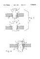
- FIG. 1is a side view of a monopole antenna constructed with a loading disc between a ground plane disc and a top loaded antenna disc;
- FIG. 2is a fragmentary section view of a feed point of the antenna shown in FIG. 1;
- FIG. 3is a fragmentary section view of a connection of a coaxial cable with the loading disc as shown in FIG. 1;
- FIG. 4is a fragmentary section view of a connection of a coaxial cable with a ground plane disc and a loading disc;
- FIG. 5is a graph of VSWR values over a bandwidth of frequencies on both sides of a center frequency of the antenna as shown in FIG. 1.
- a monopole antenna 1 constructed as a top loaded disc antennacomprises, a ground plane disc 2, a top loaded antenna disc 3, and a length of coaxial cable 4 having an outer conductor 5 connected to the ground plane disc 2, and a loading disc 6 between the ground plane disc 2 and the antenna disc 3, the loading disc 4 being connected to the outer conductor 5 of the cable
- FIG. 2A feed point of the antenna 1 is shown in FIG. 2.
- an inner conductor 7, of the cable 4is connected by a solder joint to the antenna disc 3, at an aperture concentric with a center axis.
- the inner conductor 7protrudes from a concentrically surrounding insulation 8, of the cable 1.
- the outer conductor 5 of the cable 1is spaced away from the antenna disc 3 by a protruding portion of the concentric insulation 8 of the cable 1 that is concentric with the inner conductor 7 of the cable 1.
- the space between the outer conductor and the antenna disc 3is 0.015 inch.
- the external diameter of the cable 4is 0.085 inch.
- the cable 4projects through an aperture 9 concentric with the central axis of the ground plane disc 2, with the outer conductor 5 of the cable 4 being terminated to the ground plane disc 2, for example, by a solder connection 10, FIG. 3.
- a coaxial connectorhaving a characteristic impedance matched to that of the coaxial cable, can be a blind mate connector or a threaded connector, and can be used to terminate the outer conductor 5, and the center or inner conductor 7 of the cable 1.
- a semirigid coaxial cable 4is one wherein the outer conductor 5 is tubular, rigid, nonperforated metal.
- the semirigid coaxial cable 4is stiff, capable of extending straight and is self-supporting.
- the semirigid coaxial cable 4is difficult to flex. Accordingly, it may be desired to terminate an end of such a cable 4 to a coaxial connector that is mounted on the ground plane disc 2, rather than to project the cable 1 through the ground plane disc 2, as in FIG. 3, and having to flex and route the cable 4 where it extends below the ground plane disc 2.
- a coaxial connectoris described in U.S. Pat. No. 3,778,535, incorporated herein by reference, which is especially suited to terminate an end of a semirigid coaxial cable, for example, RG 141, wherein the outer conductor 5 is tubular, nonperforated metal.
- the outer conductor 5 of the cable 4is terminated to the ground plane disc 2, either by the solder connection 9, or by the coaxial connector.
- the semi-rigid cable 1is self-supporting and provides a mast for supporting the disc antenna 3 and the loading disc 4 above the ground plane disc 2.
- a semi-rigid coaxial cablemeaning, one having a rigid outer conductor 5, mechanically supports the antenna disc 3 above the ground plane disc 2.
- the need for a supporting structure, other than the coaxial cable 4,is advantageously eliminated, since the overall length of the coaxial cable 4 is short enough for the cable 4 to be self-supporting.
- a sleeve of conducting metalcan encircle the outer conductor of the cable.
- the larger diameter of such a sleeve, as compared with the diameter of the cable,would change marginally the impedance values over the band of frequencies.
- the antenna 1is constructed with a ground plane disc 2 of 18 inches diameter and 0.025 inches thickness, an antenna disc 3 of 1.5 inches diameter and 0.025 inches thickness, and a coaxial cable 4 of 0.050 inches outer diameter.
- the antennacan be tuned to a center frequency of 0.850 GHz., which requires the overall height of the antenna to be 2.0 inches, to provide a 20% band width of 200 megacycles with WSWR less than 2:1.
- the coaxial cable 1needs to be of sufficient length to elevate the antenna disc 3 to a required distance above the ground plane disc 2.
- the loading disc 6is of 2.0 inches diameter and 0.025 inches thickness.
- the coaxial cable 4passes continuously through the center axis of the loading disc 6, wherein, the coaxial cable 4 passes continuously through an aperture 11 concentric with a center axis of the loading disc 6.
- the outer conductor 5 of the cable 4is connected by a solder joint 12 to the loading disc 6 at the aperture 11.
- the loading disc 6has a height from the ground plane disc 2 that is adjusted to resonate at the target frequency, or center frequency, 0.880 GHz., of the frequency band width. Because the loading disc 6 is relatively thin, a hollow cylindrical bushing 13, FIGS.
- the coaxial cable 4passes through the bushing 13 as well as the aperture 11 in which the bushing 13 is located. Both the cable 4 and the bushing 13 are soldered by respective solder joints 12 in the aperture 11.
- the loading disc 6is adjusted in position between the ground plane disc 2 and the antenna disc 3 for optimum VSWR in conjunction with its mechanical diameter. Also extended bandwidth, greater than usual bandwidth, is attained with gain over the entire frequency range.
- the loading disc 6is adjusted in position by sliding the loading disc 6 along the outer conductor 5 of the coaxial cable 4 that provides a mast of the antenna 1. For various positions, the termination impedance values and a VSWR chart over the band of frequencies are measured and plotted. A VSWR of less than 2:1 over a 20% bandwidth at 0.850 GHz.
- center frequencyis achieved by the antenna 1 constructed with an overall antenna height of merely 1.115 inches length, with the loading disc of 2.0 inches diameter, positioned along the coaxial cable 4 mast at 0.465 inches and 0.650 inches between the ground plane disc 2 and the top of the antenna 1, respectively.
- data point number 2measures -9.54 dB at 0.8500 GHz.
- Data point number 1is -10.188 dB at 0.8200 GHz.
- Data point number 3is -11.805 dB at 0.8960 GHz.
- a top loaded antenna 1 with an antenna disc 3 of 1.5 inches diameter, approximately one-quarter wavelength diameter,is reduced in height from 2.0 inches to 1.115 inches, by the use of the loading disc 6, and the bandwidth accompanied by substantial gain over the bandwidth is increased from 15% to 20%.
Landscapes
- Waveguide Aerials (AREA)
- Details Of Aerials (AREA)
Abstract
Description
Claims (4)
Priority Applications (1)
| Application Number | Priority Date | Filing Date | Title |
|---|---|---|---|
| US08/622,226US5706016A (en) | 1996-03-27 | 1996-03-27 | Top loaded antenna |
Applications Claiming Priority (1)
| Application Number | Priority Date | Filing Date | Title |
|---|---|---|---|
| US08/622,226US5706016A (en) | 1996-03-27 | 1996-03-27 | Top loaded antenna |
Publications (1)
| Publication Number | Publication Date |
|---|---|
| US5706016Atrue US5706016A (en) | 1998-01-06 |
Family
ID=24493400
Family Applications (1)
| Application Number | Title | Priority Date | Filing Date |
|---|---|---|---|
| US08/622,226Expired - Fee RelatedUS5706016A (en) | 1996-03-27 | 1996-03-27 | Top loaded antenna |
Country Status (1)
| Country | Link |
|---|---|
| US (1) | US5706016A (en) |
Cited By (15)
| Publication number | Priority date | Publication date | Assignee | Title |
|---|---|---|---|---|
| US5847682A (en)* | 1996-09-16 | 1998-12-08 | Ke; Shyh-Yeong | Top loaded triangular printed antenna |
| US5936587A (en)* | 1996-11-05 | 1999-08-10 | Samsung Electronics Co., Ltd. | Small antenna for portable radio equipment |
| WO2000019561A1 (en)* | 1998-09-29 | 2000-04-06 | Richard Hirschmann Of America, Inc. | Disk antenna |
| US6064347A (en)* | 1997-12-29 | 2000-05-16 | Scientific-Atlanta, Inc. | Dual frequency, low profile antenna for low earth orbit satellite communications |
| US6188366B1 (en)* | 1998-06-04 | 2001-02-13 | Matsushita Electric Industrial Co., Ltd. | Monopole antenna |
| US20040175684A1 (en)* | 2001-07-11 | 2004-09-09 | Johannes Kaasa | System and methods for interactive training of procedures |
| US20060273971A1 (en)* | 2005-06-03 | 2006-12-07 | Raytheon Company, A Corporation Of The State Of Delaware | Top loaded disk monopole antenna |
| US20070024521A1 (en)* | 2004-03-04 | 2007-02-01 | Susumu Inatsugu | Monopole antenna |
| EP2100345A4 (en)* | 2006-11-23 | 2009-11-18 | Emw Antenna Co Ltd | Antenna of parallel-ring type |
| US20090289868A1 (en)* | 2008-05-20 | 2009-11-26 | Roke Manor Research Limited | Ground plane |
| EP2122754A4 (en)* | 2007-01-11 | 2009-12-30 | Emw Antenna Co Ltd | Integrated antenna of parallel-ring type |
| CN106129587A (en)* | 2016-06-27 | 2016-11-16 | 澳门大学 | A kind of multiband back cavity type monopole antenna introducing low-frequency resonant point |
| RU202704U1 (en)* | 2020-10-06 | 2021-03-03 | Федеральное государственное автономное образовательное учреждение высшего образования "Санкт-Петербургский государственный электротехнический университет "ЛЭТИ" им. В.И. Ульянова (Ленина) (СПбГЭТУ "ЛЭТИ") | Low profile antenna |
| US11264725B2 (en)* | 2015-12-31 | 2022-03-01 | Huawei Technologies Co., Ltd. | Antenna apparatus and terminal |
| CN114883795A (en)* | 2022-05-31 | 2022-08-09 | 上海海积信息科技股份有限公司 | Antenna |
Citations (6)
| Publication number | Priority date | Publication date | Assignee | Title |
|---|---|---|---|---|
| US3787865A (en)* | 1972-05-23 | 1974-01-22 | Namac Rese Labor Inc | Discone antenna |
| US4635068A (en)* | 1985-06-05 | 1987-01-06 | Hazeltine Corporation | Double-tuned disc loaded monopole |
| US4987423A (en)* | 1988-04-01 | 1991-01-22 | Thomson-Csf | Wide band loop antenna with disymmetrical feeding, notably antenna for transmission, and array antenna formed by several such antennas |
| US5099249A (en)* | 1987-10-13 | 1992-03-24 | Seavey Engineering Associates, Inc. | Microstrip antenna for vehicular satellite communications |
| US5181044A (en)* | 1989-11-15 | 1993-01-19 | Matsushita Electric Works, Ltd. | Top loaded antenna |
| US5184143A (en)* | 1989-06-01 | 1993-02-02 | Motorola, Inc. | Low profile antenna |
- 1996
- 1996-03-27USUS08/622,226patent/US5706016A/ennot_activeExpired - Fee Related
Patent Citations (6)
| Publication number | Priority date | Publication date | Assignee | Title |
|---|---|---|---|---|
| US3787865A (en)* | 1972-05-23 | 1974-01-22 | Namac Rese Labor Inc | Discone antenna |
| US4635068A (en)* | 1985-06-05 | 1987-01-06 | Hazeltine Corporation | Double-tuned disc loaded monopole |
| US5099249A (en)* | 1987-10-13 | 1992-03-24 | Seavey Engineering Associates, Inc. | Microstrip antenna for vehicular satellite communications |
| US4987423A (en)* | 1988-04-01 | 1991-01-22 | Thomson-Csf | Wide band loop antenna with disymmetrical feeding, notably antenna for transmission, and array antenna formed by several such antennas |
| US5184143A (en)* | 1989-06-01 | 1993-02-02 | Motorola, Inc. | Low profile antenna |
| US5181044A (en)* | 1989-11-15 | 1993-01-19 | Matsushita Electric Works, Ltd. | Top loaded antenna |
Non-Patent Citations (2)
| Title |
|---|
| A.G. Kandoian, "Three New Antenna Types and Their Applications"; Proc. IRE, 34, 70W -75W, Feb. 1946. |
| A.G. Kandoian, Three New Antenna Types and Their Applications ; Proc. IRE, 34, 70W 75W, Feb. 1946.* |
Cited By (19)
| Publication number | Priority date | Publication date | Assignee | Title |
|---|---|---|---|---|
| US5847682A (en)* | 1996-09-16 | 1998-12-08 | Ke; Shyh-Yeong | Top loaded triangular printed antenna |
| US5936587A (en)* | 1996-11-05 | 1999-08-10 | Samsung Electronics Co., Ltd. | Small antenna for portable radio equipment |
| US6064347A (en)* | 1997-12-29 | 2000-05-16 | Scientific-Atlanta, Inc. | Dual frequency, low profile antenna for low earth orbit satellite communications |
| US6188366B1 (en)* | 1998-06-04 | 2001-02-13 | Matsushita Electric Industrial Co., Ltd. | Monopole antenna |
| WO2000019561A1 (en)* | 1998-09-29 | 2000-04-06 | Richard Hirschmann Of America, Inc. | Disk antenna |
| US6292152B1 (en) | 1998-09-29 | 2001-09-18 | Phazar Antenna Corp. | Disk antenna |
| US20040175684A1 (en)* | 2001-07-11 | 2004-09-09 | Johannes Kaasa | System and methods for interactive training of procedures |
| US20070024521A1 (en)* | 2004-03-04 | 2007-02-01 | Susumu Inatsugu | Monopole antenna |
| US7391374B2 (en)* | 2004-03-04 | 2008-06-24 | Matsushita Electric Industrial Co., Ltd. | Monopole antenna |
| US20060273971A1 (en)* | 2005-06-03 | 2006-12-07 | Raytheon Company, A Corporation Of The State Of Delaware | Top loaded disk monopole antenna |
| US7265727B2 (en)* | 2005-06-03 | 2007-09-04 | Raytheon Company | Top loaded disk monopole antenna |
| EP2100345A4 (en)* | 2006-11-23 | 2009-11-18 | Emw Antenna Co Ltd | Antenna of parallel-ring type |
| EP2122754A4 (en)* | 2007-01-11 | 2009-12-30 | Emw Antenna Co Ltd | Integrated antenna of parallel-ring type |
| US20090289868A1 (en)* | 2008-05-20 | 2009-11-26 | Roke Manor Research Limited | Ground plane |
| US11264725B2 (en)* | 2015-12-31 | 2022-03-01 | Huawei Technologies Co., Ltd. | Antenna apparatus and terminal |
| CN106129587A (en)* | 2016-06-27 | 2016-11-16 | 澳门大学 | A kind of multiband back cavity type monopole antenna introducing low-frequency resonant point |
| CN106129587B (en)* | 2016-06-27 | 2019-02-01 | 澳门大学 | A kind of multiband back cavity type monopole antenna introducing low-frequency resonant point |
| RU202704U1 (en)* | 2020-10-06 | 2021-03-03 | Федеральное государственное автономное образовательное учреждение высшего образования "Санкт-Петербургский государственный электротехнический университет "ЛЭТИ" им. В.И. Ульянова (Ленина) (СПбГЭТУ "ЛЭТИ") | Low profile antenna |
| CN114883795A (en)* | 2022-05-31 | 2022-08-09 | 上海海积信息科技股份有限公司 | Antenna |
Similar Documents
| Publication | Publication Date | Title |
|---|---|---|
| US6137445A (en) | Antenna apparatus for mobile terminal | |
| US5706016A (en) | Top loaded antenna | |
| US5999132A (en) | Multi-resonant antenna | |
| EP0590534B1 (en) | Portable radio unit | |
| CA2343729C (en) | Circularly polarized dielectric resonator antenna | |
| US6049314A (en) | Wide band antenna having unitary radiator/ground plane | |
| US5231412A (en) | Sleeved monopole antenna | |
| CA2318799C (en) | Dual band antenna for radio terminal | |
| US4608574A (en) | Backfire bifilar helix antenna | |
| US6268834B1 (en) | Inductively shorted bicone antenna | |
| EP2154752B1 (en) | Multi-band ceiling antenna | |
| US6567045B2 (en) | Wide-angle circular polarization antenna | |
| AU718583B2 (en) | Broad band antenna | |
| US5387919A (en) | Dipole antenna having co-axial radiators and feed | |
| US7173576B2 (en) | Handset quadrifilar helical antenna mechanical structures | |
| JPS6259922B2 (en) | ||
| US7053839B2 (en) | Antenna for a portable communication apparatus, and a portable communication apparatus comprising such an antenna | |
| US4142190A (en) | Microstrip feed with reduced aperture blockage | |
| US3950757A (en) | Broadband whip antennas | |
| JPS63224404A (en) | Patch antenna | |
| US5485165A (en) | Broadband high efficiency full wave open coaxial stub loop antenna | |
| US4611214A (en) | Tactical high frequency array antennas | |
| EP0989628B1 (en) | Patch antenna having flexed ground plate | |
| JP2005536088A (en) | Multi-band antenna and manufacturing method thereof | |
| US4556889A (en) | Aircraft trailing ball antenna |
Legal Events
| Date | Code | Title | Description |
|---|---|---|---|
| AS | Assignment | Owner name:WHITAKER CORPORATION, THE, DELAWARE Free format text:ASSIGNMENT OF ASSIGNORS INTEREST;ASSIGNOR:HARRISON, FRANK B., II.;REEL/FRAME:008603/0420 Effective date:19960325 | |
| FPAY | Fee payment | Year of fee payment:4 | |
| FEPP | Fee payment procedure | Free format text:PAYOR NUMBER ASSIGNED (ORIGINAL EVENT CODE: ASPN); ENTITY STATUS OF PATENT OWNER: LARGE ENTITY | |
| FPAY | Fee payment | Year of fee payment:8 | |
| AS | Assignment | Owner name:COBHAM DEFENSE ELECTRONIC SYSTEMS CORPORATION, MAS Free format text:ASSIGNMENT OF ASSIGNORS INTEREST;ASSIGNORS:M/A COM, INC.;RAYCHEM INTERNATIONAL;TYCO ELECTRONICS CORPORATION;AND OTHERS;REEL/FRAME:022266/0400;SIGNING DATES FROM 20080108 TO 20090113 Owner name:COBHAM DEFENSE ELECTRONIC SYSTEMS CORPORATION,MASS Free format text:ASSIGNMENT OF ASSIGNORS INTEREST;ASSIGNORS:M/A COM, INC.;RAYCHEM INTERNATIONAL;TYCO ELECTRONICS CORPORATION;AND OTHERS;SIGNING DATES FROM 20080108 TO 20090113;REEL/FRAME:022266/0400 Owner name:COBHAM DEFENSE ELECTRONIC SYSTEMS CORPORATION, MAS Free format text:ASSIGNMENT OF ASSIGNORS INTEREST;ASSIGNORS:M/A COM, INC.;RAYCHEM INTERNATIONAL;TYCO ELECTRONICS CORPORATION;AND OTHERS;SIGNING DATES FROM 20080108 TO 20090113;REEL/FRAME:022266/0400 | |
| REMI | Maintenance fee reminder mailed | ||
| LAPS | Lapse for failure to pay maintenance fees | ||
| STCH | Information on status: patent discontinuation | Free format text:PATENT EXPIRED DUE TO NONPAYMENT OF MAINTENANCE FEES UNDER 37 CFR 1.362 | |
| FP | Lapsed due to failure to pay maintenance fee | Effective date:20100106 |