US5704941A - Tibial preparation apparatus and method - Google Patents
Tibial preparation apparatus and methodDownload PDFInfo
- Publication number
- US5704941A US5704941AUS08/552,594US55259495AUS5704941AUS 5704941 AUS5704941 AUS 5704941AUS 55259495 AUS55259495 AUS 55259495AUS 5704941 AUS5704941 AUS 5704941A
- Authority
- US
- United States
- Prior art keywords
- head
- proximal tibia
- tibia
- alignment shaft
- fixation pin
- Prior art date
- Legal status (The legal status is an assumption and is not a legal conclusion. Google has not performed a legal analysis and makes no representation as to the accuracy of the status listed.)
- Expired - Lifetime
Links
- 238000000034methodMethods0.000titleclaimsabstractdescription14
- 238000002360preparation methodMethods0.000titleabstractdescription4
- 238000002271resectionMethods0.000claimsabstractdescription285
- 210000002303tibiaAnatomy0.000claimsabstractdescription265
- 230000007246mechanismEffects0.000claimsabstractdescription6
- 238000004873anchoringMethods0.000claimsdescription64
- 239000007943implantSubstances0.000claimsdescription38
- 241001422033ThestylusSpecies0.000claimsdescription32
- 230000006872improvementEffects0.000claimsdescription32
- 210000003127kneeAnatomy0.000claimsdescription29
- 230000008878couplingEffects0.000claimsdescription17
- 238000010168coupling processMethods0.000claimsdescription17
- 238000005859coupling reactionMethods0.000claimsdescription17
- 230000000295complement effectEffects0.000claimsdescription11
- 230000008901benefitEffects0.000description9
- 210000000988bone and boneAnatomy0.000description5
- 238000010276constructionMethods0.000description3
- 230000006835compressionEffects0.000description2
- 238000007906compressionMethods0.000description2
- 230000003247decreasing effectEffects0.000description2
- 238000004321preservationMethods0.000description2
- 230000009471actionEffects0.000description1
- 230000000881depressing effectEffects0.000description1
- 238000013461designMethods0.000description1
- 238000000605extractionMethods0.000description1
- 230000013011matingEffects0.000description1
- 230000000717retained effectEffects0.000description1
Images


Classifications
- A—HUMAN NECESSITIES
- A61—MEDICAL OR VETERINARY SCIENCE; HYGIENE
- A61B—DIAGNOSIS; SURGERY; IDENTIFICATION
- A61B17/00—Surgical instruments, devices or methods
- A61B17/14—Surgical saws
- A61B17/15—Guides therefor
- A61B17/154—Guides therefor for preparing bone for knee prosthesis
- A61B17/157—Cutting tibia
Definitions
- the present inventionrelates generally to the implant of prosthetic joints and pertains, more specifically, to the preparation of the proximal tibia for the implant of a tibial knee prosthesis.
- instrumentation and methodare provided for location and alignment of the proximal cut of the tibia.
- a wide variety of instrumentshave been made available for attaining the appropriate location and orientation of the proximal cut of the tibia for the implant of the tibial component of a knee prosthesis.
- these instrumentslocate a tibial resection guide, with the aid of either extramedullary or intramedullary alignment members, for affixation to the proximal tibia to provide a guide for a cutting device, such as a saw blade, which makes the proximal cut of the tibia at a selected resection level.
- the present inventionprovides apparatus and method which utilize an extramedullary alignment shaft for locating the tibial resection guide with greater ease and increased accuracy, and enabling relatively uninhibited access to the tibial resection guide, once the tibial resection guide is located appropriately at a resection location, for the accomplishment of the desired proximal cut.
- the present inventionattains several objects and advantages, some of which are summarized as follows: Enables increased accuracy, with ease, by allowing the independent setting of each alignment variable during placement and alignment of an external alignment member, prior to coupling a tibial resection guide with the external alignment member at an appropriate resection location; facilitates the location and affixation of the tibial resection guide at the desired resection location after independent accurate alignment of the external alignment member relative to the tibia; enables the removal of the external alignment member, subsequent to affixation of the tibial resection guide at the resection location, with minimal to no disruption of the alignment of the tibial resection guide at the resection location, to provide uninhibited access to the tibial resection guide for accomplishing the proximal cut at the selected resection level; provides an arrangement of component parts which reduces the potential for impeded operation of the resection device as the resection device is guided through the proximal cut of the tibi
- the present inventionwhich may be described briefly as an improvement in an apparatus used in connection with the implant of a prosthetic knee implant wherein the proximal tibia of a tibia is prepared for resection at a selected resection level for the reception of a tibial component of the prosthetic knee implant, the proximal tibia having a tibial eminence, the improvement comprising: an external alignment shaft including an upper segment and a lower segment located along a common alignment axis, the upper segment being selectively movable along the alignment axis relative to the lower segment and having an exposed upper end; a head at the exposed upper end of the upper segment, the head extending rearwardly for placement over the tibial eminence when the alignment shaft is located forward of the tibia; anchoring means on the head for anchoring the head to the proximal tibia with the alignment shaft located forward of the tibia; clamping means on
- the inventionincludes an improvement in a method for implanting a prosthetic knee implant wherein the proximal tibia of a tibia is prepared for resection at a selected resection level for the reception of a tibial component of the prosthetic knee implant, the proximal tibia having a tibial eminence, the improvement comprising: locating an external alignment shaft having an upper segment and a lower segment, forward of the tibia, the upper segment being selectively movable along an alignment axis relative to the lower segment and having an exposed upper end and a head at the exposed upper end of the upper segment, with the head extending rearwardly relative to the tibia; placing the head over the tibial eminence when the alignment shaft is located forward of the tibia; anchoring the head to the proximal tibia with anchoring means, with the alignment shaft located forward of the tibia; clamping the upper segment and the lower segment of the alignment shaft against movement relative to one another
- the inventionincludes an improvement in an apparatus used in connection with the implant of a prosthetic knee implant wherein the proximal tibia of a tibia is prepared for resection for the reception of a tibial component of the prosthetic knee implant, the proximal tibia having a tibial eminence, the improvement comprising: an external alignment shaft having an upper end; a head at the upper end of the external alignment shaft, the head extending rearwardly for placement over the tibial eminence when the alignment shaft is located forward of the tibia; and anchoring means on the head for anchoring the head to the proximal tibia with the alignment shaft located forward of the tibia; the anchoring means including a first fixation pin for anchoring the head against anterior and posterior movements relative to the tibia, and a second fixation pin for anchoring the head against rotation about the first fixation pin, at least one of the first and second fixation pins being mounted in the head for selective movement in upward and downward
- the inventionincludes an improvement in an apparatus used in connection with the implant of a prosthetic knee implant wherein the proximal tibia of a tibia is prepared for resection for the reception of a tibial component of the prosthetic knee implant, the proximal tibia having a tibial eminence, the improvement comprising: an external alignment shaft having an upper end; a head at the upper end of the external alignment shaft, the head extending rearwardly for placement over the tibial eminence when the alignment shaft is located forward of the tibia; and anchoring means on the head for anchoring the head to the proximal tibia with the alignment shaft located forward of the tibia, the anchoring means including: a first fixation pin mounted in the head for selective movement in upward and downward directions relative to the head between an advanced position wherein the first fixation pin extends downwardly from the head for extending into the proximal tibia to anchor the head to the proximal tibia
- the inventionincludes an improvement in an apparatus used in connection with the implant of a prosthetic joint wherein the bone of the natural joint is prepared for resection at a selected resection location for the reception of a component of the prosthetic joint, the improvement comprising: an alignment shaft for anchoring to the bone of the natural joint, the alignment shaft having an alignment axis; and a resection guide having coupling means for placement over the alignment shaft to engage the resection guide with the alignment shaft and enable movement of the resection guide along the alignment shaft to locate the resection guide at the resection location wherein the resection guide is located for guiding resection of the bone; the coupling means of the resection guide including securing means for selectively securing the resection guide against movement along the alignment shaft when the resection guide is located at the resection location; the alignment shaft including an outer surface having opposite side edges and a portion having a wedge-shaped surface contour configuration transverse to the alignment axis and tapered toward at least one of the opposite side edges; and the s
- the inventionfurther includes an improvement in an apparatus used in connection with the implant of a prosthetic knee implant wherein the proximal tibia of a tibia is prepared for resection at a selected resection level for the reception of a tibial component of the prosthetic knee implant, the proximal tibia having a tibial eminence, the improvement comprising: an external alignment shaft for anchoring to the tibia; a tibial resection guide having coupling means for placement upon the alignment shaft to engage the tibial resection guide with the alignment shaft and enable movement of the tibial resection guide along the alignment shaft, subsequent to anchoring the alignment shaft to the tibia; and a stylus assembly having attachment means for attaching the stylus assembly to the tibial resection guide for movement with the tibial resection guide along the alignment shaft, the stylus assembly including a stylus engageable with the proximal tibia to locate the tibial resection guide
- the inventionfurther includes an improvement in a method used in connection with the implant of a prosthetic knee implant wherein the proximal tibia of a tibia is prepared for resection at a selected resection level for the reception of a tibial component of the prosthetic knee implant, the proximal tibia having a tibial eminence, the improvement comprising: locating an external alignment shaft forward of the tibia, the external alignment shaft having an upper end, and a head at the upper end of the external alignment shaft, the head extending rearwardly for placement over the tibial eminence when the alignment shaft is located forward of the tibia; and anchoring the head to the proximal tibia with anchoring means, with the alignment shaft located forward of the tibia, the anchoring means including a first fixation pin for anchoring the head against anterior and posterior movements relative to the tibia, and a second fixation pin for anchoring the head against rotation about the first fixation pin, at least
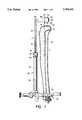
- FIG. 1is a side elevational view showing initial placement of an apparatus constructed in accordance with the present invention, along the tibia in accordance with method of the present invention;
- FIG. 2is an enlarged fragmentary view of a portion of FIG. 1, partially broken away, and with component parts shown in another position;
- FIG. 3is a fragmentary plan view of a portion of component parts illustrated in FIG. 2;
- FIG. 4is a side elevational view similar to FIG. 1, but with the apparatus fully in place along the tibia;
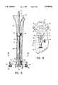
- FIG. 5is a front elevational view of the apparatus fully in place along the tibia
- FIG. 6is a transverse cross-sectional view taken along line 6--6 of FIG. 5;
- FIG. 7is an exploded perspective view of a tibial resection guide and stylus assembly of the apparatus about to be placed over the exposed upper end of the alignment shaft of the apparatus;
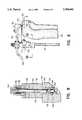
- FIG. 8is an enlarged cross-sectional view taken along line 8--8 of FIG. 7, with the stylus assembly attached to the tibial resection guide;
- FIG. 9is fragmentary side elevational view showing the tibial resection guide and stylus assembly in place upon the alignment shaft of the apparatus;
- FIG. 10is an enlarged cross-sectional view taken along line 10--10 of FIG. 9;
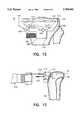
- FIG. 11is a fragmentary side elevational view showing the removal of a component part of the apparatus.
- FIG. 12is a fragmentary front elevational view showing the tibial resection guide in place at a resection location for resection of the proximal tibia;
- FIG. 13is a fragmentary side elevational view showing resection of the proximal tibia.
- the proximal tibia 20 of a tibia 22includes a tibial eminence 24 and an anterior cortex 26 and is to be prepared for the reception of the tibial component of a prosthetic knee implant (not shown) by resection of the proximal tibia 20.
- Tibia 22includes a long axis L and a distal tibia 28.
- Apparatus constructed in accordance with the invention for the preparation of the proximal tibia 20is illustrated generally at 30 and is seen to include an external alignment shaft 32 having an upper segment in the form of a rod 34 and a lower segment in the form of a tubular member 36.
- Rod 34includes an upper end 38 and a lower end 40 (see FIG. 11) and is to be received within tubular member 36 in telescoping engagement adjacent the lower end 40, for selective movement relative to the tubular member 36 along a common alignment axis A.
- Clamping meansshown in the form of a thumbscrew 42 threaded through a collar 44 integral with the tubular member 36 at the upper end 46 of the tubular member 36, selectively clamps the rod 34 in place at any location of rod 34 along alignment axis A relative to tubular member 36, when the rod 34 is telescoped into the tubular member 36.
- a head 50is integral with the rod 34 and extends rearwardly, in the posterior direction, from the upper end 38 of rod 34.
- Head 50carries anchoring means in the form of a first fixation pin 52 and a second fixation pin 54.
- Each fixation pin 52 and 54includes a pointed lower end 56 and a headed upper end 58 and is mounted in the head 50 for sliding movement in upward and downward directions, relative to the head 50, between a lower, advanced position, wherein the pointed lower end 56 extends downwardly from the head 50, as seen at 60 in FIG. 1, and an upper, retracted position, wherein the pointed lower end 56 is retracted into the head 50, as seen at 62 in FIG. 2.
- FIG. 1As best seen in FIG.
- fixation pin 52 and 54places each fixation pin 52 and 54 within a complementary bore 64 in the head 50, captured for sliding movement between the advanced and retracted positions by means of a peg 66 fixed in the head 50 and passing through a groove 68 in each fixation pin 52 and 54.
- fixation pins 52 and 54are aligned in front-to-back arrangement, with first fixation pin 52 located behind, or spaced posterior of, second fixation pin 54.
- a lower clamp 70is mounted at the lower end 72 of the tubular member 36 and includes a yoke 74 having diverging arms 76 and a jaw 78 journaled upon each arm 76.
- Lower clamp 70is placed around the distal tibia 28, just above the malleoli, and the jaws 78 are biased into a closed, clamping configuration by springs 80, thereby locating the lower end 72 of the tubular member 36 and, consequently, the lower end of the alignment shaft 32, in alignment with the distal tibia 28, forward of the distal tibia 28.
- the biasing force of springs 80is adjustable by virtue of knobs 82 which can be moved to selectively increase or decrease the force exerted by springs 80 on the respective jaws 78.
- Rod 34then is telescoped downwardly within tubular member 36 until head 50 is seated upon proximal tibia 20, placed over the tibial eminence 24 and located such that the rod 34 is forward of the anterior cortex 26 of the proximal tibia 20.
- the fixation pins 52 and 54then are centered over the tibial eminence 24 and the most posterior fixation pin 52 is pushed downwardly into the advanced position to enter the proximal tibia 20 and anchor the head 50 against anterior and posterior movements relative to the proximal tibia 20.
- rotationis adjusted by rotating the head 50 about the advanced fixation pin 52 to align the upper end 38 of the rod 34 with the tibia 22, and the most anterior fixation pin 54 is pushed downwardly into the advanced position to enter the proximal tibia 20 and anchor the head 50 against rotation relative to the proximal tibia 20.
- Thumbscrew 42then is tightened to clamp rod 34 against further movement relative to tubular member 36.
- Alignment meansis shown in the form of an alignment assembly 90 which includes a first carriage 92 integral with the lower end 72 of the tubular member 36 and mounted for sliding movement along a first guideway 94 which, in turn, is carried by a second carriage 96 mounted for sliding movement along a second guideway 98 integral with the yoke 74 of clamp 70.
- the first guideway 94has a rectangular cross-sectional configuration and extends in an anterior-posterior direction for enabling the first carriage 92 to be moved selectively along the first guideway 94 in anterior and posterior directions so as to align axis A of the alignment shaft 32 appropriately with the long axis L of the tibia 22, in the anterior and posterior directions.
- the second guideway 98has a T-shaped cross-sectional configuration and extends in a medial-lateral direction for enabling the second carriage 96 to be moved selectively along the second guideway 98 in medial and lateral directions so as to align axis A of the alignment shaft 32 appropriately with the long axis L of the tibia 22, in the medial and lateral directions.
- a first thumbscrew 100 in the first carriage 92is tightened to secure the first carriage 92 in place on the first guideway 94
- a second thumbscrew 102 in the second carriage 96is tightened to secure the second carriage 96 in place on the second guideway 98.
- a tibial resection guide 110is to be assembled with the alignment shaft 32 and located at an appropriate resection location for the accomplishment of the desired proximal cut along the proximal tibia 20.
- tibial resection guide 110includes a cutting guide surface, shown in the form of a saw blade guide slot 112 extending in a medial-lateral direction between the sides of the tibial resection guide 110 and through the tibial resection guide 110 in the anterior-posterior direction.
- a plurality of holes 114also extend through the tibial resection guide 110 in the anterior-posterior direction.
- the tibial resection guide 110is provided with coupling means including a depending sleeve-like extension 118 of the tibial resection guide 110 and a channel 120 passing through the tibial resection guide 110, and the extension 118 thereof, in the direction parallel to the alignment axis A of the alignment shaft 32 and having an inner surface 122 with a contour configuration generally complementary to the contour configuration of outer surface 124 of the rod 34 of the alignment shaft 32, at the upper end 38 of the rod 34.
- the coupling means of the tibial resection guide 110is placed over the exposed upper end 38 of the rod 34, from above the exposed upper end 38, as illustrated in FIG.
- the resection location of the tibial resection guide 110is determined by a stylus assembly 130 which is most conveniently attached to the tibial resection guide 110 prior to placement of the tibial resection guide 110 on the rod 34.
- Stylus assembly 130includes a tibial stylus 132 mounted upon a stylus housing 134 and is selectively attached to and detached from the tibial resection guide 110 by attachment means shown in the form of a quick-connect mechanism 136.
- Quick-connect mechanism 136includes an elongate plug 140 projecting downwardly from the stylus housing 134 to be received within a selected one of two complementary elongate sockets 142 extending downwardly into the tibial resection guide 110, the tibial resection guide 110 being provided with one elongate socket 142 adjacent each side of the tibial resection guide 110.
- a recess in the form of an annular groove 144 in the tibial resection guide 110communicates with the socket 142 and extends transverse to the socket 142 for the reception of a projection in the form of a ball 146 retained within the plug 140 and mounted in the plug 140 for movement between an extended position, wherein the ball 146 is in position to engage the groove 144 to secure the plug 140 within the socket 142, and a retracted position, wherein the ball is retracted into the plug 140 and out of the groove 144 to release the plug 140 from the socket 142.
- diametrically opposed balls 146engage groove 144 for enhanced securement.
- Actuator meansis shown in the form of a plunger 150 mounted for sliding movement within a bore 152 in the stylus housing 134 and including a pushbutton 154 affixed to the upper end of the plunger 150.
- the plunger 150is coupled with the balls 146 so that upon placement of the plunger 150 in an upper position, as seen in FIG. 7, the balls 146 are moved to the extended positions thereof and engage the groove 144 to secure the stylus assembly 130 in place, attached to the tibial resection guide 110.
- a compression spring 156biases the plunger 150 into the upper position thereof.
- the plunger 150Upon depression of the pushbutton 154, the plunger 150 is moved downwardly, against the bias of compression spring 156, thereby registering an annular recess 158 in the plunger 150 with the balls 146, enabling the balls 146 to move to the retracted position thereof, out of engagement with the groove 144, and the plug 140 is released for movement out of the socket 142.
- the tibial stylus 132includes a slotted bar 160 and opposite stylus tips 162 and 164.
- the slotted bar 160is clamped to the stylus housing 134 by a clamping member 166 secured by a clamping thumbnut 168, with either one of the stylus tips 162 or 164 placed in position to overlie the proximal tibia 20 when the tibial resection guide 110 is assembled with the alignment shaft 32, as described above.
- the slotted bar 160enables selected anterior and posterior movements of the stylus 132 to locate the stylus tip 162, or the stylus tip 164, appropriately prior to clamping the stylus 132 in place in the stylus assembly 130.
- the tibial resection guide 110is moved downwardly along the rod 34 until the tip 162 of tibial stylus 132 engages the proximal tibia 20, along the tibial plateau 170, thereby placing the tibial resection guide 110 at the correct resection location for accomplishing the proximal cut at the desired resection level RL.
- the quick-connect mechanism 136accomplishes a highly stable attachment of the stylus assembly 130 to the tibial resection guide 110 in a compact and easily operated arrangement.
- improved accuracyis attained in the location of the resection level RL, with a decrease in the time required for accomplishing accuracy, to the benefit of the patient and the surgeon.
- the two stylus tips 162 and 164are located at different elevations to enable the surgeon to choose one of two resection levels.
- placement of the stylus tip 162 in position to engage the tibial plateau 170locates the tibial resection guide 110, and the saw blade guide slot 112 thereof, in position to allow for a resection of 2 mm of bone below the elevation of the stylus tip 162.
- placement of the stylus tip 164 in position to engage the tibial plateau 170locates the tibial resection guide 110 in position to allow for a resection of 8 mm of bone below the elevation of the stylus tip 164.
- the securing meansincludes a securing member in the form of a thumbscrew 180 threaded into the extension 118 of the tibial resection guide 110 to engage the rod 34 in the channel 120 and clamp the tibial resection guide 110 in place on the rod 34.
- a knob 182which is the operator element of the thumbscrew 180, extends along a longitudinal axis aligned with the medial-lateral direction to project in a sideways direction from the extension 118, the knob 182 projecting in a medial-lateral direction from the medial side of the tibial resection guide 110.
- the placement of the thumbscrew 180, with the knob 182 projecting in the medial-lateral direction from the medial side of the tibial resection guide 110assures that the knob 182 will be out of the way of the resection device when making the proximal cut, as explained below.
- the contour configuration of the outer surface 124 of rod 34follows a double-wedge profile; that is, the outer surface 124 includes opposite side edges 190, a first portion 192 having a wedge-shaped surface contour configuration transverse to the alignment axis A and tapered toward one of the opposite side edges 190, and a second portion 194 having a wedge-shaped surface contour configuration transverse to the alignment axis A and tapered toward the other of the opposite side edges 190.
- the inner surface 122 of channel 120follows a double-wedge profile generally complementary to the double-wedge profile of the outer surface 124 of rod 34 and includes a first portion 196 having a wedge-shaped surface contour configuration generally complementary to that of first portion 192, and a second portion 198 having a wedge-shaped surface contour configuration generally complementary to that of second portion 194.
- the complementary first portions 192 and 196are wedged together to establish a secure connection between the extension 118 of the tibial resection guide 110 and the rod 34.
- the purpose of the double-wedge profileis to provide the same wedging action in both a right and a left tibial resection guide, while maintaining the desired medial location of the thumbscrew.
- the illustrated tibial resection guide 110is for use in connection with a left knee and the thumbscrew 180, which projects from the medial side of the extension 118, engages one side edge 190 of the rod 34 to wedge together the portions 192 and 196.
- the medial and lateral sidesare the reverse of the illustrated tibial resection guide 110 and, in order to project from the medial side of the extension of the tibial resection guide, the corresponding thumbscrew would engage the opposite side edge 190 of the rod 34, thereby wedging together the portions 194 and 198 to secure the tibial resection guide in place on the rod 34.
- alignment shaft 32, with rod 34 thereofis available for use in connection with both a right knee and a left knee.
- the stylus assembly 130is detached from the tibial resection guide 110 by merely depressing the pushbutton 154 to release the plug 140 from the socket 142, as described above.
- the tibial resection guide 110then is affixed to the proximal tibia 20 by affixation means, shown in the form of drill-pins 200 inserted through selected holes 114 in the tibial resection guide 110 and into the proximal tibia 20.
- the thumbscrew 180is loosened to release the securement of the tibial resection guide 110 on the rod 34
- the thumbscrew 42is loosened to release rod 34 for movement relative to tubular member 36
- the fixation pins 52 and 54are extracted from the proximal tibia 20.
- the rod 34then is removed by upward movement to withdraw the rod 34 from the tubular member 36 and from the tibial resection guide 110.
- fixation pins 52 and 54are mounted for sliding movement within the head 50, extraction of the fixation pins 52 and 54 is accomplished independent of any movement of head 50, and the orientation of the alignment shaft 32 remains undisturbed, thereby eliminating any concomitant forces which could dislodge the tibial resection guide 110 and disturb the placement and alignment of the tibial resection guide 110 at the resection location and, consequently, the alignment of the proximal cut.
- the tibial resection guide 110is moved along the drill-pins 200 in the posterior direction until the tibial resection guide 110 comes into contact with the proximal tibia 20, as seen in FIG. 13.
- the tibial resection guide 110is fully exposed for uninhibited access to the tibial resection guide 110 and a saw blade 210 of a saw 212 then is inserted through the saw blade guide slot 112 to accomplish the proximal cut 214 at the resection level RL.
- the knob 182 of thumbscrew 180(see FIG. 12) is out of the way of saw 212, by virtue of the medial location of the thumbscrew 180 and the projection of the knob 182 in the medial-lateral direction.
- the present inventionattains the objects and advantages summarized above; namely: Enables increased accuracy, with ease, by allowing the independent setting of each alignment variable during placement and alignment of an external alignment member, prior to coupling a tibial resection guide with the external alignment member at an appropriate resection location; facilitates the location and affixation of the tibial resection guide at the desired resection location after independent accurate alignment of the external alignment member relative to the tibia; enables the removal of the external alignment member, subsequent to affixation of the tibial resection guide at the resection location, with minimal to no disruption of the alignment of the tibial resection guide at the resection location, to provide uninhibited access to the tibial resection guide for accomplishing the proximal cut at the selected resection level; provides an arrangement of component parts which reduces the potential for impeded operation of the resection device as the resection device is guided through the proximal cut of the tibia
Landscapes
- Health & Medical Sciences (AREA)
- Life Sciences & Earth Sciences (AREA)
- Surgery (AREA)
- Dentistry (AREA)
- Biomedical Technology (AREA)
- Oral & Maxillofacial Surgery (AREA)
- Nuclear Medicine, Radiotherapy & Molecular Imaging (AREA)
- Physical Education & Sports Medicine (AREA)
- Orthopedic Medicine & Surgery (AREA)
- Engineering & Computer Science (AREA)
- Transplantation (AREA)
- Heart & Thoracic Surgery (AREA)
- Medical Informatics (AREA)
- Molecular Biology (AREA)
- Animal Behavior & Ethology (AREA)
- General Health & Medical Sciences (AREA)
- Public Health (AREA)
- Veterinary Medicine (AREA)
- Surgical Instruments (AREA)
Abstract
Description
Claims (27)
Priority Applications (1)
| Application Number | Priority Date | Filing Date | Title |
|---|---|---|---|
| US08/552,594US5704941A (en) | 1995-11-03 | 1995-11-03 | Tibial preparation apparatus and method |
Applications Claiming Priority (1)
| Application Number | Priority Date | Filing Date | Title |
|---|---|---|---|
| US08/552,594US5704941A (en) | 1995-11-03 | 1995-11-03 | Tibial preparation apparatus and method |
Publications (1)
| Publication Number | Publication Date |
|---|---|
| US5704941Atrue US5704941A (en) | 1998-01-06 |
Family
ID=24206003
Family Applications (1)
| Application Number | Title | Priority Date | Filing Date |
|---|---|---|---|
| US08/552,594Expired - LifetimeUS5704941A (en) | 1995-11-03 | 1995-11-03 | Tibial preparation apparatus and method |
Country Status (1)
| Country | Link |
|---|---|
| US (1) | US5704941A (en) |
Cited By (202)
| Publication number | Priority date | Publication date | Assignee | Title |
|---|---|---|---|---|
| EP0839501A2 (en) | 1996-10-30 | 1998-05-06 | Osteonics Corp. | Apparatus and method for the alignment of a total knee prosthesis |
| US6027507A (en)* | 1998-04-30 | 2000-02-22 | Innomed, Inc. | Leg length gauge for total hip surgery |
| EP1040791A1 (en)* | 1999-04-01 | 2000-10-04 | Aesculap | Tibial cutting guide with adjustment handgrip |
| US6190390B1 (en)* | 1999-10-29 | 2001-02-20 | Howmedica Osteonics Corp. | Apparatus and method for creating a dome tibial osteotomy |
| US20020133160A1 (en)* | 2001-02-28 | 2002-09-19 | Axelson Stuart L. | Systems used in performing femoral and tibial resection in knee surgery |
| US20020198451A1 (en)* | 2001-02-27 | 2002-12-26 | Carson Christopher P. | Surgical navigation systems and processes for high tibial osteotomy |
| US20030004516A1 (en)* | 2001-06-30 | 2003-01-02 | Yoon Yong San | Robot mounting apparatus for hip joint operation robot and hip joint operation robot system using the same |
| US20030069585A1 (en)* | 2001-10-10 | 2003-04-10 | Axelson Stuart L. | Methods and tools for femoral resection in knee surgery |
| US20030069591A1 (en)* | 2001-02-27 | 2003-04-10 | Carson Christopher Patrick | Computer assisted knee arthroplasty instrumentation, systems, and processes |
| US20030100906A1 (en)* | 2001-11-28 | 2003-05-29 | Rosa Richard A. | Methods of minimally invasive unicompartmental knee replacement |
| US20030181918A1 (en)* | 2002-02-11 | 2003-09-25 | Crista Smothers | Image-guided fracture reduction |
| WO2003045256A3 (en)* | 2001-11-28 | 2003-11-20 | Wright Medical Tech Inc | Instrumentation for minimally invasive unicompartmental knee replacement |
| US20040006391A1 (en)* | 1999-10-22 | 2004-01-08 | Archus Orthopedics Inc. | Facet arthroplasty devices and methods |
| US6685711B2 (en) | 2001-02-28 | 2004-02-03 | Howmedica Osteonics Corp. | Apparatus used in performing femoral and tibial resection in knee surgery |
| US6702824B2 (en) | 1999-09-10 | 2004-03-09 | Depuy Orthopaedics, Inc. | Prosthesis positioning apparatus |
| US20040052363A1 (en)* | 2000-05-09 | 2004-03-18 | Gn Netcom, Inc. | Headset communication unit |
| US20040138670A1 (en)* | 2003-01-15 | 2004-07-15 | Robert Metzger | Method and apparatus for less invasive knee resection |
| US20040186580A1 (en)* | 2003-01-30 | 2004-09-23 | Steinmann Scott P. | Radial head replacement system |
| US20040230201A1 (en)* | 2003-05-14 | 2004-11-18 | Archus Orthopedics Inc. | Prostheses, tools and methods for replacement of natural facet joints with artifical facet joint surfaces |
| US20040230304A1 (en)* | 2003-05-14 | 2004-11-18 | Archus Orthopedics Inc. | Prostheses, tools and methods for replacement of natural facet joints with artifical facet joint surfaces |
| US20040249387A1 (en)* | 2003-04-25 | 2004-12-09 | Francisco Faoro | Apparatus for the preparation of a femoral condyle |
| US20040267270A1 (en)* | 2003-06-30 | 2004-12-30 | Jacobs Andrew M. | Implant stabilizing instrument, kit and method |
| US20050021037A1 (en)* | 2003-05-29 | 2005-01-27 | Mccombs Daniel L. | Image-guided navigated precision reamers |
| US20050043799A1 (en)* | 1999-10-22 | 2005-02-24 | Archus Orthopedics Inc. | Facet arthroplasty devices and methods |
| US20050070910A1 (en)* | 2001-08-10 | 2005-03-31 | Greg Keene | Tibial resection guide |
| US20050075632A1 (en)* | 2003-10-03 | 2005-04-07 | Russell Thomas A. | Surgical positioners |
| US20050085822A1 (en)* | 2003-10-20 | 2005-04-21 | Thornberry Robert C. | Surgical navigation system component fault interfaces and related processes |
| US20050113840A1 (en)* | 2003-01-15 | 2005-05-26 | Robert Metzger | Method and apparatus for less invasive knee resection |
| US20050113659A1 (en)* | 2003-11-26 | 2005-05-26 | Albert Pothier | Device for data input for surgical navigation system |
| US20050113846A1 (en)* | 2001-02-27 | 2005-05-26 | Carson Christopher P. | Surgical navigation systems and processes for unicompartmental knee arthroplasty |
| US20050109855A1 (en)* | 2003-11-25 | 2005-05-26 | Mccombs Daniel | Methods and apparatuses for providing a navigational array |
| US20050119639A1 (en)* | 2003-10-20 | 2005-06-02 | Mccombs Daniel L. | Surgical navigation system component fault interfaces and related processes |
| US20050119748A1 (en)* | 1999-10-22 | 2005-06-02 | Reiley Mark A. | Prostheses, systems and methods for replacement of natural facet joints with artificial facet joint surfaces |
| US20050124988A1 (en)* | 2003-10-06 | 2005-06-09 | Lauralan Terrill-Grisoni | Modular navigated portal |
| US20050131406A1 (en)* | 2003-12-15 | 2005-06-16 | Archus Orthopedics, Inc. | Polyaxial adjustment of facet joint prostheses |
| US20050143818A1 (en)* | 2003-05-14 | 2005-06-30 | Hansen Yuan | Prostheses, tools and methods for replacement of natural facet joints with artifical facet joint surfaces |
| US20050143746A1 (en)* | 2003-12-26 | 2005-06-30 | Steffensmeier Scott J. | Adjustable resection guide |
| US20050149042A1 (en)* | 2003-01-15 | 2005-07-07 | Robert Metzger | Instrumentation for knee resection |
| US20050154394A1 (en)* | 2004-01-14 | 2005-07-14 | Michalowicz Joseph J. | Variable angle cutting block |
| US20050159759A1 (en)* | 2004-01-20 | 2005-07-21 | Mark Harbaugh | Systems and methods for performing minimally invasive incisions |
| US20050171548A1 (en)* | 2003-11-18 | 2005-08-04 | Kelman David C. | Surgical technique and instrumentation for minimal incision hip arthroplasty surgery |
| US20050182415A1 (en)* | 2003-12-26 | 2005-08-18 | Zimmer Technology, Inc. | Adjustable resection guide |
| US20050197569A1 (en)* | 2004-01-22 | 2005-09-08 | Mccombs Daniel | Methods, systems, and apparatuses for providing patient-mounted surgical navigational sensors |
| US20050228266A1 (en)* | 2004-03-31 | 2005-10-13 | Mccombs Daniel L | Methods and Apparatuses for Providing a Reference Array Input Device |
| US20050228404A1 (en)* | 2004-04-12 | 2005-10-13 | Dirk Vandevelde | Surgical navigation system component automated imaging navigation and related processes |
| US20050234465A1 (en)* | 2004-03-31 | 2005-10-20 | Mccombs Daniel L | Guided saw with pins |
| US20050234466A1 (en)* | 2004-03-31 | 2005-10-20 | Jody Stallings | TLS adjustable block |
| US20050234332A1 (en)* | 2004-01-16 | 2005-10-20 | Murphy Stephen B | Method of computer-assisted ligament balancing and component placement in total knee arthroplasty |
| US20050240266A1 (en)* | 2004-04-22 | 2005-10-27 | Kuiper Mark K | Crossbar spinal prosthesis having a modular design and related implantation methods |
| US20050235508A1 (en)* | 2004-04-22 | 2005-10-27 | Archus Orthopedics, Inc. | Facet joint prosthesis measurement and implant tools |
| US20050245808A1 (en)* | 2004-04-21 | 2005-11-03 | Carson Christopher P | Computer-aided methods, systems, and apparatuses for shoulder arthroplasty |
| WO2005110249A1 (en)* | 2004-05-17 | 2005-11-24 | Imp Limited | Apparatus for use in orthopaedic surgery |
| US20050267579A1 (en)* | 1999-10-22 | 2005-12-01 | Reiley Mark A | Implantable device for facet joint replacement |
| US20050279368A1 (en)* | 2004-06-16 | 2005-12-22 | Mccombs Daniel L | Computer assisted surgery input/output systems and processes |
| US20060036257A1 (en)* | 2004-08-06 | 2006-02-16 | Zimmer Technology, Inc. | Tibial spacer blocks and femoral cutting guide |
| US20060052785A1 (en)* | 2004-08-18 | 2006-03-09 | Augostino Teena M | Adjacent level facet arthroplasty devices, spine stabilization systems, and methods |
| US20060058806A1 (en)* | 2004-08-31 | 2006-03-16 | Howmedica Osteonics Corp. | Modular capture with magnetic attachment |
| US20060079895A1 (en)* | 2004-09-30 | 2006-04-13 | Mcleer Thomas J | Methods and devices for improved bonding of devices to bone |
| US20060085072A1 (en)* | 2004-04-22 | 2006-04-20 | Archus Orthopedics, Inc. | Implantable orthopedic device component selection instrument and methods |
| US20060085075A1 (en)* | 2004-10-04 | 2006-04-20 | Archus Orthopedics, Inc. | Polymeric joint complex and methods of use |
| US20060100707A1 (en)* | 2003-07-08 | 2006-05-11 | David Stinson | Prostheses, tools and methods for replacement of natural facet joints with artificial facet joint surfaces |
| US20060142774A1 (en)* | 2003-01-15 | 2006-06-29 | Biomet Manufacturing Corp. | Instrumentation for knee resection |
| US20060149276A1 (en)* | 2002-12-20 | 2006-07-06 | Grimm James E | Surgical instrument and positioning method |
| US20060161051A1 (en)* | 2005-01-18 | 2006-07-20 | Lauralan Terrill-Grisoni | Method of computer-assisted ligament balancing and component placement in total knee arthroplasty |
| US20060190011A1 (en)* | 2004-12-02 | 2006-08-24 | Michael Ries | Systems and methods for providing a reference plane for mounting an acetabular cup during a computer-aided surgery |
| US20060200159A1 (en)* | 2005-02-18 | 2006-09-07 | Howmedica Osteonics Corp. | Pin extraction assembly |
| US20060200025A1 (en)* | 2004-12-02 | 2006-09-07 | Scott Elliott | Systems, methods, and apparatus for automatic software flow using instrument detection during computer-aided surgery |
| US20060247647A1 (en)* | 2002-11-27 | 2006-11-02 | Zimmer Technology, Inc. | Method and apparatus for achieving correct limb alignment in unicondylar knee arthroplasty |
| GB2426198A (en)* | 2005-05-17 | 2006-11-22 | Biomet Uk Ltd | Stylus assembly for use with a surgical jig |
| WO2006136955A1 (en)* | 2005-06-03 | 2006-12-28 | Depuy Ireland Limited | Instrument for use in a joint replacement procedure |
| US20070088358A1 (en)* | 2005-03-22 | 2007-04-19 | Hansen Yuan | Minimally Invasive Spine Restoration Systems, Devices, Methods and Kits |
| US20070093833A1 (en)* | 2004-05-03 | 2007-04-26 | Kuiper Mark K | Crossbar spinal prosthesis having a modular design and related implantation methods |
| US20070118055A1 (en)* | 2005-11-04 | 2007-05-24 | Smith & Nephew, Inc. | Systems and methods for facilitating surgical procedures involving custom medical implants |
| US20070233256A1 (en)* | 2006-03-15 | 2007-10-04 | Ohrt John A | Facet and disc arthroplasty system and method |
| US20070233140A1 (en)* | 2006-02-27 | 2007-10-04 | Biomet Manufacturing Corp. | Femoral adjustment device and associated method |
| US20070276374A1 (en)* | 2005-03-02 | 2007-11-29 | Richard Broman | Arthroplasty revision system and method |
| US20070282451A1 (en)* | 2006-05-31 | 2007-12-06 | Biomet Manufacturing Corp. | Prosthesis and implementation system |
| US20070288030A1 (en)* | 2006-06-09 | 2007-12-13 | Biomet Manufacturing Corp. | Patient Specific Knee Alignment Guide And Associated Method |
| US20070287910A1 (en)* | 2004-04-15 | 2007-12-13 | Jody Stallings | Quick Disconnect and Repositionable Reference Frame for Computer Assisted Surgery |
| US20080082171A1 (en)* | 2004-04-22 | 2008-04-03 | Kuiper Mark K | Crossbar spinal prosthesis having a modular design and systems for treating spinal pathologies |
| US20080091205A1 (en)* | 2004-04-22 | 2008-04-17 | Kuiper Mark K | Crossbar Spinal Prosthesis Having a Modular Design and Related Implantation Methods |
| US20080103501A1 (en)* | 2006-08-11 | 2008-05-01 | Ralph Christopher R | Angled Washer Polyaxial Connection for Dynamic Spine Prosthesis |
| US20080114370A1 (en)* | 2006-06-09 | 2008-05-15 | Biomet Manufacturing Corp. | Patient-Specific Alignment Guide For Multiple Incisions |
| US20080177310A1 (en)* | 2000-10-20 | 2008-07-24 | Archus Orthopedics, Inc. | Facet arthroplasty devices and methods |
| GB2447328A (en)* | 2007-03-06 | 2008-09-10 | Stryker Leibinger Gmbh & Co Kg | An orthopaedic jig having releasably held sliding pins |
| US20080275566A1 (en)* | 2007-05-04 | 2008-11-06 | Lewis Randall J | Femoral hip stem explant system |
| US20080312659A1 (en)* | 2006-02-27 | 2008-12-18 | Biomet Manufacturing Corp. | Patient specific alignment guide and inter-operative adjustment |
| US20090024131A1 (en)* | 2006-02-27 | 2009-01-22 | Biomet Manufacturing Corp. | Patient specific guides |
| US7488324B1 (en) | 2003-12-08 | 2009-02-10 | Biomet Manufacturing Corporation | Femoral guide for implanting a femoral knee prosthesis |
| US20090066845A1 (en)* | 2005-05-26 | 2009-03-12 | Takao Okuda | Content Processing Apparatus, Method of Processing Content, and Computer Program |
| US20090105837A1 (en)* | 2005-06-03 | 2009-04-23 | Lafosse Laurent | Instrument for use in a joint replacement procedure |
| US20090132045A1 (en)* | 2005-06-03 | 2009-05-21 | Lafosse Laurent | Instrument for use in a joint replacement procedure |
| US20090163922A1 (en)* | 2006-02-27 | 2009-06-25 | Biomet Manufacturing Corp. | Patient Specific Acetabular Guide And Method |
| US20090254093A1 (en)* | 2006-06-09 | 2009-10-08 | Biomet Manufacturing Corp. | Patient-Specific Alignment Guide |
| US7648510B2 (en) | 2003-09-15 | 2010-01-19 | Zimmer, Gmbh | Adjustment apparatus |
| US20100087829A1 (en)* | 2006-02-27 | 2010-04-08 | Biomet Manufacturing Corp. | Patient Specific Alignment Guide With Cutting Surface and Laser Indicator |
| US7695479B1 (en) | 2005-04-12 | 2010-04-13 | Biomet Manufacturing Corp. | Femoral sizer |
| US20100121331A1 (en)* | 2003-11-18 | 2010-05-13 | Sharp Jeffrey A | Universal double offset surgical instrument |
| US20100152782A1 (en)* | 2006-02-27 | 2010-06-17 | Biomet Manufactring Corp. | Patient Specific High Tibia Osteotomy |
| US7780671B2 (en) | 2006-01-23 | 2010-08-24 | Zimmer Technology, Inc. | Bone resection apparatus and method for knee surgery |
| US7794467B2 (en) | 2003-11-14 | 2010-09-14 | Smith & Nephew, Inc. | Adjustable surgical cutting systems |
| US20110015636A1 (en)* | 2006-02-27 | 2011-01-20 | Biomet Manufacturing Corp. | Patient-Specific Elbow Guides and Associated Methods |
| WO2011018647A1 (en)* | 2009-08-12 | 2011-02-17 | Biomet Uk Limited | Stylus assembly |
| US20110093086A1 (en)* | 2006-02-27 | 2011-04-21 | Witt Tyler D | Patient-Specific Hip Joint Devices |
| US20110092804A1 (en)* | 2006-02-27 | 2011-04-21 | Biomet Manufacturing Corp. | Patient-Specific Pre-Operative Planning |
| US20110160736A1 (en)* | 2006-02-27 | 2011-06-30 | Biomet Manufacturing Corp. | Patient-specific femoral guide |
| US20110166578A1 (en)* | 2006-02-27 | 2011-07-07 | Biomet Manufacturing Corp. | Alignment guides with patient-specific anchoring elements |
| US20110172672A1 (en)* | 2006-02-27 | 2011-07-14 | Biomet Manufacturing Corp. | Instrument with transparent portion for use with patient-specific alignment guide |
| US20110184526A1 (en)* | 2007-04-17 | 2011-07-28 | Biomet Manufacturing Corp. | Patient-modified implant |
| US20110190899A1 (en)* | 2006-02-27 | 2011-08-04 | Biomet Manufacturing Corp. | Patient-specific augments |
| US20110213376A1 (en)* | 2010-02-26 | 2011-09-01 | Biomet Sports Medicine, Llc | Patient-Specific Osteotomy Devices and Methods |
| US20110218545A1 (en)* | 2010-03-04 | 2011-09-08 | Biomet Manufacturing Corp. | Patient-specific computed tomography guides |
| US20120053594A1 (en)* | 2010-08-31 | 2012-03-01 | Benoit Pelletier | Tool and method for digital acquisition of a tibial mechanical axis |
| US8170641B2 (en) | 2009-02-20 | 2012-05-01 | Biomet Manufacturing Corp. | Method of imaging an extremity of a patient |
| US8177788B2 (en) | 2005-02-22 | 2012-05-15 | Smith & Nephew, Inc. | In-line milling system |
| US8221461B2 (en) | 2004-10-25 | 2012-07-17 | Gmedelaware 2 Llc | Crossbar spinal prosthesis having a modular design and systems for treating spinal pathologies |
| US8265949B2 (en) | 2007-09-27 | 2012-09-11 | Depuy Products, Inc. | Customized patient surgical plan |
| US8282646B2 (en) | 2006-02-27 | 2012-10-09 | Biomet Manufacturing Corp. | Patient specific knee alignment guide and associated method |
| US8343159B2 (en) | 2007-09-30 | 2013-01-01 | Depuy Products, Inc. | Orthopaedic bone saw and method of use thereof |
| US8357111B2 (en) | 2007-09-30 | 2013-01-22 | Depuy Products, Inc. | Method and system for designing patient-specific orthopaedic surgical instruments |
| US8407067B2 (en) | 2007-04-17 | 2013-03-26 | Biomet Manufacturing Corp. | Method and apparatus for manufacturing an implant |
| US8425522B2 (en) | 2000-01-14 | 2013-04-23 | Bonutti Skeletal Innovations Llc | Joint replacement method |
| US8473305B2 (en) | 2007-04-17 | 2013-06-25 | Biomet Manufacturing Corp. | Method and apparatus for manufacturing an implant |
| US8496686B2 (en) | 2005-03-22 | 2013-07-30 | Gmedelaware 2 Llc | Minimally invasive spine restoration systems, devices, methods and kits |
| US20130226185A1 (en)* | 2000-01-14 | 2013-08-29 | Bonutti Skeletal Innovations Llc | Femoral guide for knee surgery |
| US8532807B2 (en) | 2011-06-06 | 2013-09-10 | Biomet Manufacturing, Llc | Pre-operative planning and manufacturing method for orthopedic procedure |
| US8535387B2 (en) | 2006-02-27 | 2013-09-17 | Biomet Manufacturing, Llc | Patient-specific tools and implants |
| US8591516B2 (en) | 2006-02-27 | 2013-11-26 | Biomet Manufacturing, Llc | Patient-specific orthopedic instruments |
| US8597365B2 (en) | 2011-08-04 | 2013-12-03 | Biomet Manufacturing, Llc | Patient-specific pelvic implants for acetabular reconstruction |
| US8603180B2 (en) | 2006-02-27 | 2013-12-10 | Biomet Manufacturing, Llc | Patient-specific acetabular alignment guides |
| US8608749B2 (en) | 2006-02-27 | 2013-12-17 | Biomet Manufacturing, Llc | Patient-specific acetabular guides and associated instruments |
| US8623030B2 (en) | 2001-08-28 | 2014-01-07 | Bonutti Skeletal Innovations Llc | Robotic arthroplasty system including navigation |
| US8668700B2 (en) | 2011-04-29 | 2014-03-11 | Biomet Manufacturing, Llc | Patient-specific convertible guides |
| US8715289B2 (en) | 2011-04-15 | 2014-05-06 | Biomet Manufacturing, Llc | Patient-specific numerically controlled instrument |
| US8764760B2 (en) | 2011-07-01 | 2014-07-01 | Biomet Manufacturing, Llc | Patient-specific bone-cutting guidance instruments and methods |
| US8852197B2 (en) | 2011-06-30 | 2014-10-07 | Depuy (Ireland) | Surgical instrument assemblies for use in surgically preparing a tibia for implantation of a prosthetic component |
| EP2549940A4 (en)* | 2010-03-22 | 2014-12-31 | Smith & Nephew Inc | LOCKABLE ORIENTATION INSTALLATION ARRANGEMENT |
| US8926619B2 (en) | 2011-06-30 | 2015-01-06 | Depuy (Ireland) | Method of surgically preparing a tibia for implantation of a prosthetic component |
| US8939986B2 (en) | 2011-06-30 | 2015-01-27 | Depuy (Ireland) | Surgical instruments for use in surgically preparing a tibia for implantation of a prosthetic component |
| US8951301B2 (en) | 2011-06-30 | 2015-02-10 | Depuy (Ireland) | Method of using a trialing system for a knee prosthesis |
| US8956364B2 (en) | 2011-04-29 | 2015-02-17 | Biomet Manufacturing, Llc | Patient-specific partial knee guides and other instruments |
| US8968412B2 (en) | 2011-06-30 | 2015-03-03 | Depuy (Ireland) | Trialing system for a knee prosthesis and method of use |
| US8986390B2 (en) | 2011-06-30 | 2015-03-24 | Depuy (Ireland) | Method of trialing a knee prosthesis |
| US9060788B2 (en) | 2012-12-11 | 2015-06-23 | Biomet Manufacturing, Llc | Patient-specific acetabular guide for anterior approach |
| US9066734B2 (en) | 2011-08-31 | 2015-06-30 | Biomet Manufacturing, Llc | Patient-specific sacroiliac guides and associated methods |
| US9084618B2 (en) | 2011-06-13 | 2015-07-21 | Biomet Manufacturing, Llc | Drill guides for confirming alignment of patient-specific alignment guides |
| US9113971B2 (en) | 2006-02-27 | 2015-08-25 | Biomet Manufacturing, Llc | Femoral acetabular impingement guide |
| US9114012B2 (en) | 2011-06-30 | 2015-08-25 | Depuy (Ireland) | Femoral trial component |
| US9204977B2 (en) | 2012-12-11 | 2015-12-08 | Biomet Manufacturing, Llc | Patient-specific acetabular guide for anterior approach |
| US9237950B2 (en) | 2012-02-02 | 2016-01-19 | Biomet Manufacturing, Llc | Implant with patient-specific porous structure |
| US9241745B2 (en) | 2011-03-07 | 2016-01-26 | Biomet Manufacturing, Llc | Patient-specific femoral version guide |
| US9271744B2 (en) | 2010-09-29 | 2016-03-01 | Biomet Manufacturing, Llc | Patient-specific guide for partial acetabular socket replacement |
| US9289253B2 (en) | 2006-02-27 | 2016-03-22 | Biomet Manufacturing, Llc | Patient-specific shoulder guide |
| US9295497B2 (en) | 2011-08-31 | 2016-03-29 | Biomet Manufacturing, Llc | Patient-specific sacroiliac and pedicle guides |
| US9301812B2 (en) | 2011-10-27 | 2016-04-05 | Biomet Manufacturing, Llc | Methods for patient-specific shoulder arthroplasty |
| US9339278B2 (en) | 2006-02-27 | 2016-05-17 | Biomet Manufacturing, Llc | Patient-specific acetabular guides and associated instruments |
| US9351743B2 (en) | 2011-10-27 | 2016-05-31 | Biomet Manufacturing, Llc | Patient-specific glenoid guides |
| US9386993B2 (en) | 2011-09-29 | 2016-07-12 | Biomet Manufacturing, Llc | Patient-specific femoroacetabular impingement instruments and methods |
| US9393028B2 (en) | 2009-08-13 | 2016-07-19 | Biomet Manufacturing, Llc | Device for the resection of bones, method for producing such a device, endoprosthesis suited for this purpose and method for producing such an endoprosthesis |
| US9408616B2 (en) | 2014-05-12 | 2016-08-09 | Biomet Manufacturing, Llc | Humeral cut guide |
| US9451973B2 (en) | 2011-10-27 | 2016-09-27 | Biomet Manufacturing, Llc | Patient specific glenoid guide |
| US9498233B2 (en) | 2013-03-13 | 2016-11-22 | Biomet Manufacturing, Llc. | Universal acetabular guide and associated hardware |
| US9517145B2 (en) | 2013-03-15 | 2016-12-13 | Biomet Manufacturing, Llc | Guide alignment system and method |
| US9554910B2 (en) | 2011-10-27 | 2017-01-31 | Biomet Manufacturing, Llc | Patient-specific glenoid guide and implants |
| US9561040B2 (en) | 2014-06-03 | 2017-02-07 | Biomet Manufacturing, Llc | Patient-specific glenoid depth control |
| US9579107B2 (en) | 2013-03-12 | 2017-02-28 | Biomet Manufacturing, Llc | Multi-point fit for patient specific guide |
| US9675400B2 (en) | 2011-04-19 | 2017-06-13 | Biomet Manufacturing, Llc | Patient-specific fracture fixation instrumentation and method |
| US9795399B2 (en) | 2006-06-09 | 2017-10-24 | Biomet Manufacturing, Llc | Patient-specific knee alignment guide and associated method |
| US9820868B2 (en) | 2015-03-30 | 2017-11-21 | Biomet Manufacturing, Llc | Method and apparatus for a pin apparatus |
| US9826981B2 (en) | 2013-03-13 | 2017-11-28 | Biomet Manufacturing, Llc | Tangential fit of patient-specific guides |
| US9826994B2 (en) | 2014-09-29 | 2017-11-28 | Biomet Manufacturing, Llc | Adjustable glenoid pin insertion guide |
| US9833245B2 (en) | 2014-09-29 | 2017-12-05 | Biomet Sports Medicine, Llc | Tibial tubercule osteotomy |
| US9839438B2 (en) | 2013-03-11 | 2017-12-12 | Biomet Manufacturing, Llc | Patient-specific glenoid guide with a reusable guide holder |
| US9839436B2 (en) | 2014-06-03 | 2017-12-12 | Biomet Manufacturing, Llc | Patient-specific glenoid depth control |
| US9861491B2 (en) | 2014-04-30 | 2018-01-09 | Depuy Ireland Unlimited Company | Tibial trial system for a knee prosthesis |
| US9907659B2 (en) | 2007-04-17 | 2018-03-06 | Biomet Manufacturing, Llc | Method and apparatus for manufacturing an implant |
| US9918740B2 (en) | 2006-02-27 | 2018-03-20 | Biomet Manufacturing, Llc | Backup surgical instrument system and method |
| US9968376B2 (en) | 2010-11-29 | 2018-05-15 | Biomet Manufacturing, Llc | Patient-specific orthopedic instruments |
| US10195056B2 (en) | 2015-10-19 | 2019-02-05 | Depuy Ireland Unlimited Company | Method for preparing a patient's tibia to receive an implant |
| US10226262B2 (en) | 2015-06-25 | 2019-03-12 | Biomet Manufacturing, Llc | Patient-specific humeral guide designs |
| US10271857B2 (en) | 2013-12-23 | 2019-04-30 | Depuy Ireland Unlimited Company (R/F 040070/0868) | Surgical instrument |
| US10282488B2 (en) | 2014-04-25 | 2019-05-07 | Biomet Manufacturing, Llc | HTO guide with optional guided ACL/PCL tunnels |
| US10492798B2 (en) | 2011-07-01 | 2019-12-03 | Biomet Manufacturing, Llc | Backup kit for a patient-specific arthroplasty kit assembly |
| US10537445B2 (en) | 2015-10-19 | 2020-01-21 | Depuy Ireland Unlimited Company | Surgical instruments for preparing a patient's tibia to receive an implant |
| US10568647B2 (en) | 2015-06-25 | 2020-02-25 | Biomet Manufacturing, Llc | Patient-specific humeral guide designs |
| US10603179B2 (en) | 2006-02-27 | 2020-03-31 | Biomet Manufacturing, Llc | Patient-specific augments |
| US10722310B2 (en) | 2017-03-13 | 2020-07-28 | Zimmer Biomet CMF and Thoracic, LLC | Virtual surgery planning system and method |
| US11051829B2 (en) | 2018-06-26 | 2021-07-06 | DePuy Synthes Products, Inc. | Customized patient-specific orthopaedic surgical instrument |
| JP2021526954A (en)* | 2018-09-04 | 2021-10-11 | メダクタ・インターナショナル・ソシエテ・アノニム | Tibial osteotomy guide device |
| US11179165B2 (en) | 2013-10-21 | 2021-11-23 | Biomet Manufacturing, Llc | Ligament guide registration |
| WO2021247498A1 (en)* | 2020-06-01 | 2021-12-09 | Pmo Llc | Bone deformity treatment system, device, and related methods |
| US11207115B2 (en) | 2019-11-21 | 2021-12-28 | DePuy Synthes Products, LLC | System and method of coupling an alignment guide to an intramedullary nail insertion handle |
| US11419618B2 (en) | 2011-10-27 | 2022-08-23 | Biomet Manufacturing, Llc | Patient-specific glenoid guides |
| US11497509B2 (en)* | 2018-11-28 | 2022-11-15 | Aesculap Ag | Fixing clamp and aligning device |
| US11666346B2 (en) | 2007-03-23 | 2023-06-06 | Xiros Limited | Surgical templates |
| US11751883B2 (en) | 2018-11-28 | 2023-09-12 | Aesculap Ag | Fixing system and aligning device |
| US11806029B2 (en) | 2021-01-06 | 2023-11-07 | DePuy Synthes Products, Inc. | Locking trocar and method of using the same |
| EP4285845A1 (en)* | 2022-06-03 | 2023-12-06 | Aesculap AG | Surgical instrument |
| US12011199B2 (en) | 2020-10-15 | 2024-06-18 | DePuy Synthes Products, Inc. | Bone plate, bone plate system, and method of using the same |
| US12042157B2 (en) | 2019-02-15 | 2024-07-23 | Aesculap Ag | Fixing clamp and aligning device |
| US12433614B2 (en) | 2022-06-03 | 2025-10-07 | Aesculap Ag | Surgical instrument |
| US12440222B2 (en) | 2022-06-03 | 2025-10-14 | Aesculap Ag | Surgical instrument |
Citations (3)
| Publication number | Priority date | Publication date | Assignee | Title |
|---|---|---|---|---|
| US3596554A (en)* | 1970-05-19 | 1971-08-03 | Nasa | Safety-type locking pin |
| US5282803A (en)* | 1991-03-07 | 1994-02-01 | Smith & Nephew Richards Inc. | Instrumentation for long stem surgery |
| US5462550A (en)* | 1992-08-13 | 1995-10-31 | Zimmer, Inc. | Alignment guide and method |
- 1995
- 1995-11-03USUS08/552,594patent/US5704941A/ennot_activeExpired - Lifetime
Patent Citations (3)
| Publication number | Priority date | Publication date | Assignee | Title |
|---|---|---|---|---|
| US3596554A (en)* | 1970-05-19 | 1971-08-03 | Nasa | Safety-type locking pin |
| US5282803A (en)* | 1991-03-07 | 1994-02-01 | Smith & Nephew Richards Inc. | Instrumentation for long stem surgery |
| US5462550A (en)* | 1992-08-13 | 1995-10-31 | Zimmer, Inc. | Alignment guide and method |
Non-Patent Citations (3)
| Title |
|---|
| Duracon The Tibial System, Howmedica, pp. 12 15, 1994.* |
| Duracon® The Tibial System, Howmedica, pp. 12-15, 1994. |
| The P.C.A Primary Total Knee System, Howmedica Inc., 1984.* |
Cited By (489)
| Publication number | Priority date | Publication date | Assignee | Title |
|---|---|---|---|---|
| EP0839501B1 (en)* | 1996-10-30 | 2003-03-12 | Osteonics Corp. | Apparatus and method for the alignment of a total knee prosthesis |
| EP0839501A2 (en) | 1996-10-30 | 1998-05-06 | Osteonics Corp. | Apparatus and method for the alignment of a total knee prosthesis |
| US6027507A (en)* | 1998-04-30 | 2000-02-22 | Innomed, Inc. | Leg length gauge for total hip surgery |
| EP1040791A1 (en)* | 1999-04-01 | 2000-10-04 | Aesculap | Tibial cutting guide with adjustment handgrip |
| FR2791549A1 (en)* | 1999-04-01 | 2000-10-06 | Aesculap Sa | DEVICE FOR POSITIONING A PROXIMAL END OF A TIBIA RELATIVE TO A CUTTING GUIDE, INCLUDING AN ADJUSTMENT HANDLE |
| US6702824B2 (en) | 1999-09-10 | 2004-03-09 | Depuy Orthopaedics, Inc. | Prosthesis positioning apparatus |
| US8066740B2 (en) | 1999-10-22 | 2011-11-29 | Gmedelaware 2 Llc | Facet joint prostheses |
| US20050267579A1 (en)* | 1999-10-22 | 2005-12-01 | Reiley Mark A | Implantable device for facet joint replacement |
| US20080015583A1 (en)* | 1999-10-22 | 2008-01-17 | Reiley Mark A | Facet arthroplasty devices and methods |
| US20080091268A1 (en)* | 1999-10-22 | 2008-04-17 | Archus Orthopedics, Inc. | Facet arthroplasty devices and methods |
| US20080091210A1 (en)* | 1999-10-22 | 2008-04-17 | Archus Orthopedics, Inc. | Facet arthroplasty devices and methods |
| US20080097438A1 (en)* | 1999-10-22 | 2008-04-24 | Reiley Mark A | Facet Arthroplasty Devices and Methods |
| US20070282445A1 (en)* | 1999-10-22 | 2007-12-06 | Reiley Mark A | Facet arthroplasty devices and methods |
| US20080097439A1 (en)* | 1999-10-22 | 2008-04-24 | Reiley Mark A | Facet Arthroplasty Devices and Methods |
| US20070255411A1 (en)* | 1999-10-22 | 2007-11-01 | Reiley Mark A | Facet arthroplasty devices and methods |
| US20040006391A1 (en)* | 1999-10-22 | 2004-01-08 | Archus Orthopedics Inc. | Facet arthroplasty devices and methods |
| US20080097612A1 (en)* | 1999-10-22 | 2008-04-24 | Reiley Mark A | Facet Arthroplasty Devices and Methods |
| US20080091202A1 (en)* | 1999-10-22 | 2008-04-17 | Reiley Mark A | Facet Arthroplasty Devices and Methods |
| US20040049273A1 (en)* | 1999-10-22 | 2004-03-11 | Archus Orthopedics, Inc. | Facet Arthroplasty devices and methods |
| US20040049277A1 (en)* | 1999-10-22 | 2004-03-11 | Archus Orthopedics, Inc. | Facet arthroplasty devices and methods |
| US20040049276A1 (en)* | 1999-10-22 | 2004-03-11 | Archus Orthopedics, Inc. | Facet arthroplasty devices and methods |
| US20040049281A1 (en)* | 1999-10-22 | 2004-03-11 | Archus Orthopedics, Inc. | Facet arthroplasty devices and methods |
| US20040049278A1 (en)* | 1999-10-22 | 2004-03-11 | Archus Orthopedics, Inc. | Facet arthroplasty devices and methods |
| US20080086213A1 (en)* | 1999-10-22 | 2008-04-10 | Reiley Mark A | Facet arthroplasty devices and methods |
| US20050234552A1 (en)* | 1999-10-22 | 2005-10-20 | Reiley Mark A | Facet arthroplasty devices and methods |
| US20080097613A1 (en)* | 1999-10-22 | 2008-04-24 | Reiley Mark A | Prostheses, Systems and Methods for Replacement of Natural Facet Joints With Artificial Facet Joint Surfaces |
| US8066771B2 (en) | 1999-10-22 | 2011-11-29 | Gmedelaware 2 Llc | Facet arthroplasty devices and methods |
| US7608106B2 (en) | 1999-10-22 | 2009-10-27 | Archus Orthopedics, Inc. | Facet arthroplasty devices and methods |
| US20080097609A1 (en)* | 1999-10-22 | 2008-04-24 | Archus Orthopedics, Inc. | Facet arthroplasty devices and methods |
| US7691145B2 (en) | 1999-10-22 | 2010-04-06 | Facet Solutions, Inc. | Prostheses, systems and methods for replacement of natural facet joints with artificial facet joint surfaces |
| US20080015696A1 (en)* | 1999-10-22 | 2008-01-17 | Reiley Mark A | Facet arthroplasty devices and methods |
| US8070811B2 (en) | 1999-10-22 | 2011-12-06 | Gmedelaware 2 Llc | Facet arthroplasty devices and methods |
| US20090018585A1 (en)* | 1999-10-22 | 2009-01-15 | Reiley Mark A | Facet arthroplasty devices and methods |
| US8092532B2 (en) | 1999-10-22 | 2012-01-10 | Gmedelaware 2 Llc | Facet arthroplasty devices and methods |
| US20050251256A1 (en)* | 1999-10-22 | 2005-11-10 | Archus Orthopedics, Inc. | Facet arthroplasty devices and methods |
| US20050043799A1 (en)* | 1999-10-22 | 2005-02-24 | Archus Orthopedics Inc. | Facet arthroplasty devices and methods |
| US7087084B2 (en) | 1999-10-22 | 2006-08-08 | Archus Orthopedics, Inc. | Method for replacing a natural facet joint with a prosthesis having an artificial facet joint structure |
| US20050149190A1 (en)* | 1999-10-22 | 2005-07-07 | Reiley Mark A. | Facet arthroplasty devices and methods |
| US20080200953A1 (en)* | 1999-10-22 | 2008-08-21 | Reiley Mark A | Facet Joint Prostheses |
| US20050283238A1 (en)* | 1999-10-22 | 2005-12-22 | Reiley Mark A | Facet arthroplasty devices and methods |
| US20050119748A1 (en)* | 1999-10-22 | 2005-06-02 | Reiley Mark A. | Prostheses, systems and methods for replacement of natural facet joints with artificial facet joint surfaces |
| US20080097437A1 (en)* | 1999-10-22 | 2008-04-24 | Archus Orthopedics, Inc. | Facet arthroplasty devices and methods |
| US20060009847A1 (en)* | 1999-10-22 | 2006-01-12 | Reiley Mark A | Facet arthroplasty devices and methods |
| US20050137706A1 (en)* | 1999-10-22 | 2005-06-23 | Reiley Mark A. | Facet arthroplasty devices and methods |
| US20050137705A1 (en)* | 1999-10-22 | 2005-06-23 | Reiley Mark A. | Facet arthroplasty devices and methods |
| US8163017B2 (en) | 1999-10-22 | 2012-04-24 | Gmedelaware 2 Llc | Facet arthroplasty devices and methods |
| US20060009848A1 (en)* | 1999-10-22 | 2006-01-12 | Reiley Mark A | Facet arthroplasty device and methods |
| US6190390B1 (en)* | 1999-10-29 | 2001-02-20 | Howmedica Osteonics Corp. | Apparatus and method for creating a dome tibial osteotomy |
| US20130226185A1 (en)* | 2000-01-14 | 2013-08-29 | Bonutti Skeletal Innovations Llc | Femoral guide for knee surgery |
| US8632552B2 (en) | 2000-01-14 | 2014-01-21 | Bonutti Skeletal Innovations Llc | Method of preparing a femur and tibia in knee arthroplasty |
| US8425522B2 (en) | 2000-01-14 | 2013-04-23 | Bonutti Skeletal Innovations Llc | Joint replacement method |
| US9101443B2 (en) | 2000-01-14 | 2015-08-11 | Bonutti Skeletal Innovations Llc | Methods for robotic arthroplasty |
| US8784495B2 (en) | 2000-01-14 | 2014-07-22 | Bonutti Skeletal Innovations Llc | Segmental knee arthroplasty |
| US9795394B2 (en) | 2000-01-14 | 2017-10-24 | Bonutti Skeletal Innovations Llc | Method for placing implant using robotic system |
| US9192459B2 (en) | 2000-01-14 | 2015-11-24 | Bonutti Skeletal Innovations Llc | Method of performing total knee arthroplasty |
| US20040052363A1 (en)* | 2000-05-09 | 2004-03-18 | Gn Netcom, Inc. | Headset communication unit |
| US20080177310A1 (en)* | 2000-10-20 | 2008-07-24 | Archus Orthopedics, Inc. | Facet arthroplasty devices and methods |
| US20050234468A1 (en)* | 2001-02-27 | 2005-10-20 | Carson Christopher P | Total knee arthroplasty systems and processes |
| US20050113846A1 (en)* | 2001-02-27 | 2005-05-26 | Carson Christopher P. | Surgical navigation systems and processes for unicompartmental knee arthroplasty |
| US20020198451A1 (en)* | 2001-02-27 | 2002-12-26 | Carson Christopher P. | Surgical navigation systems and processes for high tibial osteotomy |
| US20110071531A1 (en)* | 2001-02-27 | 2011-03-24 | Carson Christopher P | Systems using imaging data to facilitate surgical procedures |
| US7547307B2 (en) | 2001-02-27 | 2009-06-16 | Smith & Nephew, Inc. | Computer assisted knee arthroplasty instrumentation, systems, and processes |
| US20110071528A1 (en)* | 2001-02-27 | 2011-03-24 | Carson Christopher P | Systems Using Imaging Data to Facilitate Surgical Procedures |
| US20030069591A1 (en)* | 2001-02-27 | 2003-04-10 | Carson Christopher Patrick | Computer assisted knee arthroplasty instrumentation, systems, and processes |
| US20070123912A1 (en)* | 2001-02-27 | 2007-05-31 | Carson Christopher P | Surgical navigation systems and processes for unicompartmental knee arthroplasty |
| US20110071530A1 (en)* | 2001-02-27 | 2011-03-24 | Carson Christopher P | Total knee arthroplasty systems and processes |
| US20020133160A1 (en)* | 2001-02-28 | 2002-09-19 | Axelson Stuart L. | Systems used in performing femoral and tibial resection in knee surgery |
| US6685711B2 (en) | 2001-02-28 | 2004-02-03 | Howmedica Osteonics Corp. | Apparatus used in performing femoral and tibial resection in knee surgery |
| US7909831B2 (en)* | 2001-02-28 | 2011-03-22 | Howmedica Osteonics Corp. | Systems used in performing femoral and tibial resection in knee surgery |
| US20030004516A1 (en)* | 2001-06-30 | 2003-01-02 | Yoon Yong San | Robot mounting apparatus for hip joint operation robot and hip joint operation robot system using the same |
| US7104998B2 (en)* | 2001-06-30 | 2006-09-12 | Korea Advanced Institute Of Science And Technology | Hip joint robot system and robot mounting apparatus |
| KR20030002219A (en)* | 2001-06-30 | 2003-01-08 | 한국과학기술원 | Femur clamping robot mount for robotic total hip arthroplasty |
| US20050070910A1 (en)* | 2001-08-10 | 2005-03-31 | Greg Keene | Tibial resection guide |
| US10321918B2 (en) | 2001-08-28 | 2019-06-18 | Bonutti Skeletal Innovations Llc | Methods for robotic surgery using a cannula |
| US10231739B1 (en) | 2001-08-28 | 2019-03-19 | Bonutti Skeletal Innovations Llc | System and method for robotic surgery |
| US9763683B2 (en) | 2001-08-28 | 2017-09-19 | Bonutti Skeletal Innovations Llc | Method for performing surgical procedures using optical cutting guides |
| US10470780B2 (en) | 2001-08-28 | 2019-11-12 | Bonutti Skeletal Innovations Llc | Systems and methods for ligament balancing in robotic surgery |
| US8834490B2 (en) | 2001-08-28 | 2014-09-16 | Bonutti Skeletal Innovations Llc | Method for robotic arthroplasty using navigation |
| US8641726B2 (en) | 2001-08-28 | 2014-02-04 | Bonutti Skeletal Innovations Llc | Method for robotic arthroplasty using navigation |
| US8623030B2 (en) | 2001-08-28 | 2014-01-07 | Bonutti Skeletal Innovations Llc | Robotic arthroplasty system including navigation |
| US8840629B2 (en) | 2001-08-28 | 2014-09-23 | Bonutti Skeletal Innovations Llc | Robotic arthroplasty system including navigation |
| US8858557B2 (en) | 2001-08-28 | 2014-10-14 | Bonutti Skeletal Innovations Llc | Method of preparing a femur and tibia in knee arthroplasty |
| US9060797B2 (en) | 2001-08-28 | 2015-06-23 | Bonutti Skeletal Innovations Llc | Method of preparing a femur and tibia in knee arthroplasty |
| US20080097446A1 (en)* | 2001-09-25 | 2008-04-24 | Reiley Mark A | Prostheses, Systems and Methods for Replacement of Natural Facet Joints With Artificial Facet Joint Surfaces |
| US20080097440A1 (en)* | 2001-09-25 | 2008-04-24 | Reiley Mark A | Prostheses, Systems and Methods for Replacement of Natural Facet Joints With Artificial Facet Joint Surfaces |
| US20030069585A1 (en)* | 2001-10-10 | 2003-04-10 | Axelson Stuart L. | Methods and tools for femoral resection in knee surgery |
| US7618421B2 (en)* | 2001-10-10 | 2009-11-17 | Howmedica Osteonics Corp. | Tools for femoral resection in knee surgery |
| US20030100906A1 (en)* | 2001-11-28 | 2003-05-29 | Rosa Richard A. | Methods of minimally invasive unicompartmental knee replacement |
| US7141053B2 (en) | 2001-11-28 | 2006-11-28 | Wright Medical Technology, Inc. | Methods of minimally invasive unicompartmental knee replacement |
| WO2003045256A3 (en)* | 2001-11-28 | 2003-11-20 | Wright Medical Tech Inc | Instrumentation for minimally invasive unicompartmental knee replacement |
| US7060074B2 (en) | 2001-11-28 | 2006-06-13 | Wright Medical Technology, Inc. | Instrumentation for minimally invasive unicompartmental knee replacement |
| US7237556B2 (en) | 2002-02-11 | 2007-07-03 | Smith & Nephew, Inc. | Image-guided fracture reduction |
| US20030181918A1 (en)* | 2002-02-11 | 2003-09-25 | Crista Smothers | Image-guided fracture reduction |
| US20070169782A1 (en)* | 2002-02-11 | 2007-07-26 | Crista Smothers | Image-guided fracture reduction |
| US20060247647A1 (en)* | 2002-11-27 | 2006-11-02 | Zimmer Technology, Inc. | Method and apparatus for achieving correct limb alignment in unicondylar knee arthroplasty |
| US7842039B2 (en) | 2002-11-27 | 2010-11-30 | Zimmer Technology, Inc. | Method and apparatus for achieving correct limb alignment in unicondylar knee arthroplasty |
| US8454616B2 (en) | 2002-11-27 | 2013-06-04 | Zimmer, Inc. | Method and apparatus for achieving correct limb alignment in unicondylar knee arthroplasty |
| US20060149276A1 (en)* | 2002-12-20 | 2006-07-06 | Grimm James E | Surgical instrument and positioning method |
| US7887542B2 (en) | 2003-01-15 | 2011-02-15 | Biomet Manufacturing Corp. | Method and apparatus for less invasive knee resection |
| US20050113840A1 (en)* | 2003-01-15 | 2005-05-26 | Robert Metzger | Method and apparatus for less invasive knee resection |
| US20100318089A1 (en)* | 2003-01-15 | 2010-12-16 | Robert Metzger | Method and apparatus for less invasive knee resection |
| US20050149042A1 (en)* | 2003-01-15 | 2005-07-07 | Robert Metzger | Instrumentation for knee resection |
| US9693788B2 (en) | 2003-01-15 | 2017-07-04 | Biomet Manufacturing, Llc | Instrumentation for knee resection |
| US20110130762A1 (en)* | 2003-01-15 | 2011-06-02 | Biomet Manufacturing Corp. | Method for Less Invasive Knee Resection |
| US20040138670A1 (en)* | 2003-01-15 | 2004-07-15 | Robert Metzger | Method and apparatus for less invasive knee resection |
| US7789885B2 (en) | 2003-01-15 | 2010-09-07 | Biomet Manufacturing Corp. | Instrumentation for knee resection |
| US8870883B2 (en) | 2003-01-15 | 2014-10-28 | Biomet Manufacturing, Llc | Method for less invasive knee resection |
| US9023053B2 (en) | 2003-01-15 | 2015-05-05 | Biomet Manufacturing, Llc | Instrumentation for knee resection |
| US8518047B2 (en) | 2003-01-15 | 2013-08-27 | Biomet Manufacturing, Llc | Method and apparatus for less invasive knee resection |
| US20060142774A1 (en)* | 2003-01-15 | 2006-06-29 | Biomet Manufacturing Corp. | Instrumentation for knee resection |
| US8551100B2 (en) | 2003-01-15 | 2013-10-08 | Biomet Manufacturing, Llc | Instrumentation for knee resection |
| US7837690B2 (en) | 2003-01-15 | 2010-11-23 | Biomet Manufacturing Corp. | Method and apparatus for less invasive knee resection |
| US7452381B2 (en) | 2003-01-30 | 2008-11-18 | Mayo Foundation For Medical Education And Research | Radial head replacement system |
| US20090036991A1 (en)* | 2003-01-30 | 2009-02-05 | Steinmann Scott P | Radial Head Replacement System |
| US20040186580A1 (en)* | 2003-01-30 | 2004-09-23 | Steinmann Scott P. | Radial head replacement system |
| US20040249387A1 (en)* | 2003-04-25 | 2004-12-09 | Francisco Faoro | Apparatus for the preparation of a femoral condyle |
| US7527630B2 (en) | 2003-04-25 | 2009-05-05 | Zimmer, Gmbh | Apparatus for the preparation of a femoral condyle |
| US9198766B2 (en) | 2003-05-14 | 2015-12-01 | Gmedelaware 2 Llc | Prostheses, tools, and methods for replacement of natural facet joints with artificial facet joint surfaces |
| US7608104B2 (en) | 2003-05-14 | 2009-10-27 | Archus Orthopedics, Inc. | Prostheses, tools and methods for replacement of natural facet joints with artifical facet joint surfaces |
| US20040230201A1 (en)* | 2003-05-14 | 2004-11-18 | Archus Orthopedics Inc. | Prostheses, tools and methods for replacement of natural facet joints with artifical facet joint surfaces |
| US20040230304A1 (en)* | 2003-05-14 | 2004-11-18 | Archus Orthopedics Inc. | Prostheses, tools and methods for replacement of natural facet joints with artifical facet joint surfaces |
| US20080275505A1 (en)* | 2003-05-14 | 2008-11-06 | Hansen Yuan | Prostheses, Tools and Methods for Replacement of Natural Facet Joints With Artificial Facet Joint Surfaces |
| US20060149375A1 (en)* | 2003-05-14 | 2006-07-06 | Yuan Hansen A | Prostheses, Tools And Methods For Replacement Of Natural Facet Joints With Artificial Facet Joint Surfaces |
| US8409254B2 (en) | 2003-05-14 | 2013-04-02 | Gmedelaware 2 Llc | Prostheses, tools and methods for replacement of natural facet joints with artificial facet joint surfaces |
| US20050143818A1 (en)* | 2003-05-14 | 2005-06-30 | Hansen Yuan | Prostheses, tools and methods for replacement of natural facet joints with artifical facet joint surfaces |
| US20080125814A1 (en)* | 2003-05-14 | 2008-05-29 | Archus Orthopedics, Inc. | Prostheses, tools and methods for replacement of natural facet joints with artificial facet joint surfaces |
| US20070168029A1 (en)* | 2003-05-14 | 2007-07-19 | Yuan Hansen A | Prostheses, tools and methods for replacement of natural facet joints with artificial facet joint surfaces |
| US20050021037A1 (en)* | 2003-05-29 | 2005-01-27 | Mccombs Daniel L. | Image-guided navigated precision reamers |
| US20040267270A1 (en)* | 2003-06-30 | 2004-12-30 | Jacobs Andrew M. | Implant stabilizing instrument, kit and method |
| US7473259B2 (en)* | 2003-06-30 | 2009-01-06 | Depuy Products, Inc. | Implant stabilizing instrument, kit and method |
| US20060265070A1 (en)* | 2003-07-08 | 2006-11-23 | David Stinson | Prostheses and methods for replacement of natural facet joints with artificial facet joint surfaces |
| US8231655B2 (en) | 2003-07-08 | 2012-07-31 | Gmedelaware 2 Llc | Prostheses and methods for replacement of natural facet joints with artificial facet joint surfaces |
| US20060100707A1 (en)* | 2003-07-08 | 2006-05-11 | David Stinson | Prostheses, tools and methods for replacement of natural facet joints with artificial facet joint surfaces |
| US8523907B2 (en) | 2003-07-08 | 2013-09-03 | Gmedelaware 2 Llc | Prostheses, tools and methods for replacement of natural facet joints with artificial facet joint surfaces |
| US7648510B2 (en) | 2003-09-15 | 2010-01-19 | Zimmer, Gmbh | Adjustment apparatus |
| US7862570B2 (en) | 2003-10-03 | 2011-01-04 | Smith & Nephew, Inc. | Surgical positioners |
| US8491597B2 (en) | 2003-10-03 | 2013-07-23 | Smith & Nephew, Inc. (partial interest) | Surgical positioners |
| US20050075632A1 (en)* | 2003-10-03 | 2005-04-07 | Russell Thomas A. | Surgical positioners |
| US20050124988A1 (en)* | 2003-10-06 | 2005-06-09 | Lauralan Terrill-Grisoni | Modular navigated portal |
| US20100249581A1 (en)* | 2003-10-20 | 2010-09-30 | Mccombs Daniel L | Surgical Navigation System Component Fault Interfaces and Related Processes |
| US7764985B2 (en) | 2003-10-20 | 2010-07-27 | Smith & Nephew, Inc. | Surgical navigation system component fault interfaces and related processes |
| US20050119639A1 (en)* | 2003-10-20 | 2005-06-02 | Mccombs Daniel L. | Surgical navigation system component fault interfaces and related processes |
| US20050085822A1 (en)* | 2003-10-20 | 2005-04-21 | Thornberry Robert C. | Surgical navigation system component fault interfaces and related processes |
| US7794467B2 (en) | 2003-11-14 | 2010-09-14 | Smith & Nephew, Inc. | Adjustable surgical cutting systems |
| USD677384S1 (en) | 2003-11-18 | 2013-03-05 | Smith & Nephew, Inc. | Surgical hip anterior approach arthroplasty device |
| US9622758B2 (en) | 2003-11-18 | 2017-04-18 | Smith & Nephew, Inc. | Surgical technique and instrumentation for minimal incision hip arthroplasty surgery |
| US11957363B2 (en) | 2003-11-18 | 2024-04-16 | Smith & Nephew, Inc. | Surgical technique and instrumentation for minimal incision hip arthroplasty surgery |
| US9615837B2 (en) | 2003-11-18 | 2017-04-11 | Smith & Nephew, Inc. | Surgical technique and instrumentation for minimal incision hip arthroplasty surgery |
| US8096993B2 (en) | 2003-11-18 | 2012-01-17 | Smith & Nephew, Inc. | Surgical technique and instrumentation for minimal incision hip arthroplasty surgery |
| US11219467B2 (en) | 2003-11-18 | 2022-01-11 | Smith & Nephew, Inc. | Surgical technique and instrumentation for minimal incision hip arthroplasty surgery |
| US20090275948A1 (en)* | 2003-11-18 | 2009-11-05 | Smith & Nephew, Inc. | Surgical technique and instrumentation for minimal incision hip arthroplasty surgery |
| US9526512B2 (en) | 2003-11-18 | 2016-12-27 | Smith & Nephew, Inc. | Universal double offset surgical instrument |
| US9265508B2 (en) | 2003-11-18 | 2016-02-23 | Smith & Nephew, Inc. | Surgical technique and instrumentation for minimal incision hip arthroplasty surgery |
| USD648850S1 (en) | 2003-11-18 | 2011-11-15 | Smith & Nephew, Inc. | Surgical hip anterior approach arthroplasty device |
| US7591821B2 (en) | 2003-11-18 | 2009-09-22 | Smith & Nephew, Inc. | Surgical technique and instrumentation for minimal incision hip arthroplasty surgery |
| US20100121331A1 (en)* | 2003-11-18 | 2010-05-13 | Sharp Jeffrey A | Universal double offset surgical instrument |
| US10292715B2 (en) | 2003-11-18 | 2019-05-21 | Smith & Nephew, Inc. | Surgical technique and instrumentation for minimal incision hip arthroplasty surgery |
| US8657824B2 (en) | 2003-11-18 | 2014-02-25 | Smith & Nephew, Inc. | Universal double offset surgical instrument |
| US8734451B2 (en) | 2003-11-18 | 2014-05-27 | Smith & Nephew, Inc. | Surgical technique and instrumentation for minimal hip arthroplasty surgery |
| US20050171548A1 (en)* | 2003-11-18 | 2005-08-04 | Kelman David C. | Surgical technique and instrumentation for minimal incision hip arthroplasty surgery |
| US20050109855A1 (en)* | 2003-11-25 | 2005-05-26 | Mccombs Daniel | Methods and apparatuses for providing a navigational array |
| US20050113659A1 (en)* | 2003-11-26 | 2005-05-26 | Albert Pothier | Device for data input for surgical navigation system |
| US8834486B2 (en) | 2003-12-08 | 2014-09-16 | Biomet Manufacturing, Llc | Femoral guide for implanting a femoral knee prosthesis |
| US20090149859A1 (en)* | 2003-12-08 | 2009-06-11 | Biomet Manufacturing Corp. | Femoral Guide For Implanting A Femoral Knee Prosthesis |
| US7488324B1 (en) | 2003-12-08 | 2009-02-10 | Biomet Manufacturing Corporation | Femoral guide for implanting a femoral knee prosthesis |
| US8123758B2 (en) | 2003-12-08 | 2012-02-28 | Biomet Manufacturing Corp. | Femoral guide for implanting a femoral knee prosthesis |
| US20050131406A1 (en)* | 2003-12-15 | 2005-06-16 | Archus Orthopedics, Inc. | Polyaxial adjustment of facet joint prostheses |
| US20080177332A1 (en)* | 2003-12-15 | 2008-07-24 | Archus Orthopedics, Inc. | Polyaxial adjustment of facet joint prostheses |
| US9056016B2 (en) | 2003-12-15 | 2015-06-16 | Gmedelaware 2 Llc | Polyaxial adjustment of facet joint prostheses |
| US20050143746A1 (en)* | 2003-12-26 | 2005-06-30 | Steffensmeier Scott J. | Adjustable resection guide |
| US7335206B2 (en) | 2003-12-26 | 2008-02-26 | Zimmer Technology, Inc. | Adjustable resection guide |
| US20050182415A1 (en)* | 2003-12-26 | 2005-08-18 | Zimmer Technology, Inc. | Adjustable resection guide |
| US7641661B2 (en) | 2003-12-26 | 2010-01-05 | Zimmer Technology, Inc. | Adjustable resection guide |
| US20050154394A1 (en)* | 2004-01-14 | 2005-07-14 | Michalowicz Joseph J. | Variable angle cutting block |
| US7364581B2 (en) | 2004-01-14 | 2008-04-29 | Howmedica Osteonics Corp. | Variable angle cutting block |
| US20050234332A1 (en)* | 2004-01-16 | 2005-10-20 | Murphy Stephen B | Method of computer-assisted ligament balancing and component placement in total knee arthroplasty |
| US20050159759A1 (en)* | 2004-01-20 | 2005-07-21 | Mark Harbaugh | Systems and methods for performing minimally invasive incisions |
| US20050197569A1 (en)* | 2004-01-22 | 2005-09-08 | Mccombs Daniel | Methods, systems, and apparatuses for providing patient-mounted surgical navigational sensors |
| US7477926B2 (en) | 2004-03-31 | 2009-01-13 | Smith & Nephew, Inc. | Methods and apparatuses for providing a reference array input device |
| US20050234466A1 (en)* | 2004-03-31 | 2005-10-20 | Jody Stallings | TLS adjustable block |
| US20050228266A1 (en)* | 2004-03-31 | 2005-10-13 | Mccombs Daniel L | Methods and Apparatuses for Providing a Reference Array Input Device |
| US20050234465A1 (en)* | 2004-03-31 | 2005-10-20 | Mccombs Daniel L | Guided saw with pins |
| US20050228404A1 (en)* | 2004-04-12 | 2005-10-13 | Dirk Vandevelde | Surgical navigation system component automated imaging navigation and related processes |
| US20070287910A1 (en)* | 2004-04-15 | 2007-12-13 | Jody Stallings | Quick Disconnect and Repositionable Reference Frame for Computer Assisted Surgery |
| US20050245808A1 (en)* | 2004-04-21 | 2005-11-03 | Carson Christopher P | Computer-aided methods, systems, and apparatuses for shoulder arthroplasty |
| US8109942B2 (en) | 2004-04-21 | 2012-02-07 | Smith & Nephew, Inc. | Computer-aided methods, systems, and apparatuses for shoulder arthroplasty |
| US8425557B2 (en) | 2004-04-22 | 2013-04-23 | Gmedelaware 2 Llc | Crossbar spinal prosthesis having a modular design and related implantation methods |
| US8491635B2 (en) | 2004-04-22 | 2013-07-23 | Gmedelaware 2 Llc | Crossbar spinal prosthesis having a modular design and related implantation methods |
| US7406775B2 (en) | 2004-04-22 | 2008-08-05 | Archus Orthopedics, Inc. | Implantable orthopedic device component selection instrument and methods |
| US8675930B2 (en) | 2004-04-22 | 2014-03-18 | Gmedelaware 2 Llc | Implantable orthopedic device component selection instrument and methods |
| US20080082171A1 (en)* | 2004-04-22 | 2008-04-03 | Kuiper Mark K | Crossbar spinal prosthesis having a modular design and systems for treating spinal pathologies |
| US20080091205A1 (en)* | 2004-04-22 | 2008-04-17 | Kuiper Mark K | Crossbar Spinal Prosthesis Having a Modular Design and Related Implantation Methods |
| US20050240266A1 (en)* | 2004-04-22 | 2005-10-27 | Kuiper Mark K | Crossbar spinal prosthesis having a modular design and related implantation methods |
| US20080091204A1 (en)* | 2004-04-22 | 2008-04-17 | Kuiper Mark K | Crossbar spinal prosthesis having a modular design and related implantation methods |
| US7674293B2 (en) | 2004-04-22 | 2010-03-09 | Facet Solutions, Inc. | Crossbar spinal prosthesis having a modular design and related implantation methods |
| US8187303B2 (en) | 2004-04-22 | 2012-05-29 | Gmedelaware 2 Llc | Anti-rotation fixation element for spinal prostheses |
| US20050235508A1 (en)* | 2004-04-22 | 2005-10-27 | Archus Orthopedics, Inc. | Facet joint prosthesis measurement and implant tools |
| US20060085072A1 (en)* | 2004-04-22 | 2006-04-20 | Archus Orthopedics, Inc. | Implantable orthopedic device component selection instrument and methods |
| US20080292161A1 (en)* | 2004-04-22 | 2008-11-27 | Funk Michael J | Implantable orthopedic device component selection instrument and methods |
| US7051451B2 (en) | 2004-04-22 | 2006-05-30 | Archus Orthopedics, Inc. | Facet joint prosthesis measurement and implant tools |
| US7290347B2 (en) | 2004-04-22 | 2007-11-06 | Archus Orthopedics, Inc. | Facet joint prosthesis measurement and implant tools |
| US20060184180A1 (en)* | 2004-04-22 | 2006-08-17 | Augostino Teena M | Facet Joint Prosthesis Measurement and Implant Tools |
| US8496687B2 (en) | 2004-04-22 | 2013-07-30 | Gmedelaware 2 Llc | Crossbar spinal prosthesis having a modular design and related implantation methods |
| US20070093833A1 (en)* | 2004-05-03 | 2007-04-26 | Kuiper Mark K | Crossbar spinal prosthesis having a modular design and related implantation methods |
| WO2005110249A1 (en)* | 2004-05-17 | 2005-11-24 | Imp Limited | Apparatus for use in orthopaedic surgery |
| US20050279368A1 (en)* | 2004-06-16 | 2005-12-22 | Mccombs Daniel L | Computer assisted surgery input/output systems and processes |
| US8167888B2 (en) | 2004-08-06 | 2012-05-01 | Zimmer Technology, Inc. | Tibial spacer blocks and femoral cutting guide |
| US20060036257A1 (en)* | 2004-08-06 | 2006-02-16 | Zimmer Technology, Inc. | Tibial spacer blocks and femoral cutting guide |
| US20060052785A1 (en)* | 2004-08-18 | 2006-03-09 | Augostino Teena M | Adjacent level facet arthroplasty devices, spine stabilization systems, and methods |
| US20060058791A1 (en)* | 2004-08-18 | 2006-03-16 | Richard Broman | Implantable spinal device revision system |
| US8398681B2 (en) | 2004-08-18 | 2013-03-19 | Gmedelaware 2 Llc | Adjacent level facet arthroplasty devices, spine stabilization systems, and methods |
| US20090281546A1 (en)* | 2004-08-31 | 2009-11-12 | Howmedica Osteonics Corp. | Modular capture with magnetic attachment |
| US7572261B2 (en)* | 2004-08-31 | 2009-08-11 | Howmedica Osteonics Corp. | Modular capture with magnetic attachment |
| US20060058806A1 (en)* | 2004-08-31 | 2006-03-16 | Howmedica Osteonics Corp. | Modular capture with magnetic attachment |
| US8382763B2 (en) | 2004-08-31 | 2013-02-26 | Howmedica Osteonics Corp. | Modular capture with magnetic attachment |
| US20060079895A1 (en)* | 2004-09-30 | 2006-04-13 | Mcleer Thomas J | Methods and devices for improved bonding of devices to bone |
| US20090024219A1 (en)* | 2004-10-04 | 2009-01-22 | Archus Orthopedics, Inc. | Polymeric joint complex and methods of use |
| US20080140121A1 (en)* | 2004-10-04 | 2008-06-12 | Archus Orthopedics, Inc. | Polymeric joint complex and methods of use |
| US20080177309A1 (en)* | 2004-10-04 | 2008-07-24 | Archus Orthopedics, Inc. | Polymeric joint complex and methods of use |
| US20060085075A1 (en)* | 2004-10-04 | 2006-04-20 | Archus Orthopedics, Inc. | Polymeric joint complex and methods of use |
| US8221461B2 (en) | 2004-10-25 | 2012-07-17 | Gmedelaware 2 Llc | Crossbar spinal prosthesis having a modular design and systems for treating spinal pathologies |
| US20060190011A1 (en)* | 2004-12-02 | 2006-08-24 | Michael Ries | Systems and methods for providing a reference plane for mounting an acetabular cup during a computer-aided surgery |
| US20060200025A1 (en)* | 2004-12-02 | 2006-09-07 | Scott Elliott | Systems, methods, and apparatus for automatic software flow using instrument detection during computer-aided surgery |
| US20060161051A1 (en)* | 2005-01-18 | 2006-07-20 | Lauralan Terrill-Grisoni | Method of computer-assisted ligament balancing and component placement in total knee arthroplasty |
| US20060200159A1 (en)* | 2005-02-18 | 2006-09-07 | Howmedica Osteonics Corp. | Pin extraction assembly |
| US7344542B2 (en)* | 2005-02-18 | 2008-03-18 | Howmedica Osteonics Corp. | Pin extraction assembly |
| US8177788B2 (en) | 2005-02-22 | 2012-05-15 | Smith & Nephew, Inc. | In-line milling system |
| US20070276374A1 (en)* | 2005-03-02 | 2007-11-29 | Richard Broman | Arthroplasty revision system and method |
| US7914556B2 (en) | 2005-03-02 | 2011-03-29 | Gmedelaware 2 Llc | Arthroplasty revision system and method |
| US8496686B2 (en) | 2005-03-22 | 2013-07-30 | Gmedelaware 2 Llc | Minimally invasive spine restoration systems, devices, methods and kits |
| US20070088358A1 (en)* | 2005-03-22 | 2007-04-19 | Hansen Yuan | Minimally Invasive Spine Restoration Systems, Devices, Methods and Kits |
| US7695479B1 (en) | 2005-04-12 | 2010-04-13 | Biomet Manufacturing Corp. | Femoral sizer |
| GB2426198B (en)* | 2005-05-17 | 2010-12-08 | Biomet Uk Ltd | Stylus assembly |
| GB2426198A (en)* | 2005-05-17 | 2006-11-22 | Biomet Uk Ltd | Stylus assembly for use with a surgical jig |
| US20090112212A1 (en)* | 2005-05-17 | 2009-04-30 | Biomet Uk Limited | Stylus Assembly |
| WO2006123120A1 (en)* | 2005-05-17 | 2006-11-23 | Biomet Uk Limited | Stylus assembly |
| US8221429B2 (en) | 2005-05-17 | 2012-07-17 | Biomet Uk Limited | Stylus assembly |
| JP2008545457A (en)* | 2005-05-17 | 2008-12-18 | バイオメット ユーケイ リミテッド | Stylus assembly |
| US8900242B2 (en) | 2005-05-17 | 2014-12-02 | Biomet Uk Limited | Stylus assembly |
| US20090066845A1 (en)* | 2005-05-26 | 2009-03-12 | Takao Okuda | Content Processing Apparatus, Method of Processing Content, and Computer Program |
| US8231682B2 (en) | 2005-06-03 | 2012-07-31 | Depuy Ireland Limited | Instrument for use in a joint replacement procedure |
| US8585706B2 (en)* | 2005-06-03 | 2013-11-19 | Depuy (Ireland) | Instrument for use in a joint replacement procedure |
| JP2008541914A (en)* | 2005-06-03 | 2008-11-27 | デピュイ・アイルランド・リミテッド | Instrument for use in joint replacement |
| AU2006260592B2 (en)* | 2005-06-03 | 2012-02-16 | Depuy Ireland Limited | Instrument for use in a joint replacement procedure |
| US20090222010A1 (en)* | 2005-06-03 | 2009-09-03 | Lafosse Laurent | Instrument for use in a joint replacement procedure |
| US20090105837A1 (en)* | 2005-06-03 | 2009-04-23 | Lafosse Laurent | Instrument for use in a joint replacement procedure |
| WO2006136955A1 (en)* | 2005-06-03 | 2006-12-28 | Depuy Ireland Limited | Instrument for use in a joint replacement procedure |
| JP4864967B2 (en)* | 2005-06-03 | 2012-02-01 | デピュイ・(アイルランド)・リミテッド | Instrument for use in joint replacement |
| US20090132045A1 (en)* | 2005-06-03 | 2009-05-21 | Lafosse Laurent | Instrument for use in a joint replacement procedure |
| US20070118055A1 (en)* | 2005-11-04 | 2007-05-24 | Smith & Nephew, Inc. | Systems and methods for facilitating surgical procedures involving custom medical implants |
| US20110092978A1 (en)* | 2005-11-04 | 2011-04-21 | Mccombs Daniel L | Systems and methods for facilitating surgical procedures involving custom medical implants |
| US20100286699A1 (en)* | 2006-01-23 | 2010-11-11 | Zimmer Technology, Inc. | Bone resection apparatus and method for knee surgery |
| US7780671B2 (en) | 2006-01-23 | 2010-08-24 | Zimmer Technology, Inc. | Bone resection apparatus and method for knee surgery |
| US9522010B2 (en) | 2006-02-27 | 2016-12-20 | Biomet Manufacturing, Llc | Patient-specific orthopedic instruments |
| US8608748B2 (en) | 2006-02-27 | 2013-12-17 | Biomet Manufacturing, Llc | Patient specific guides |
| US20100087829A1 (en)* | 2006-02-27 | 2010-04-08 | Biomet Manufacturing Corp. | Patient Specific Alignment Guide With Cutting Surface and Laser Indicator |
| US9539013B2 (en) | 2006-02-27 | 2017-01-10 | Biomet Manufacturing, Llc | Patient-specific elbow guides and associated methods |
| US20090163922A1 (en)* | 2006-02-27 | 2009-06-25 | Biomet Manufacturing Corp. | Patient Specific Acetabular Guide And Method |
| US10278711B2 (en) | 2006-02-27 | 2019-05-07 | Biomet Manufacturing, Llc | Patient-specific femoral guide |
| US8377066B2 (en) | 2006-02-27 | 2013-02-19 | Biomet Manufacturing Corp. | Patient-specific elbow guides and associated methods |
| US20130131681A1 (en)* | 2006-02-27 | 2013-05-23 | Biomet Manufacturing Corporation | Patient-Specific Elbow Guides And Associated Methods |
| US9662127B2 (en) | 2006-02-27 | 2017-05-30 | Biomet Manufacturing, Llc | Patient-specific acetabular guides and associated instruments |
| US9662216B2 (en) | 2006-02-27 | 2017-05-30 | Biomet Manufacturing, Llc | Patient-specific hip joint devices |
| US20100152782A1 (en)* | 2006-02-27 | 2010-06-17 | Biomet Manufactring Corp. | Patient Specific High Tibia Osteotomy |
| US9005297B2 (en)* | 2006-02-27 | 2015-04-14 | Biomet Manufacturing, Llc | Patient-specific elbow guides and associated methods |
| US20090024131A1 (en)* | 2006-02-27 | 2009-01-22 | Biomet Manufacturing Corp. | Patient specific guides |
| US9700329B2 (en) | 2006-02-27 | 2017-07-11 | Biomet Manufacturing, Llc | Patient-specific orthopedic instruments |
| US20110190899A1 (en)* | 2006-02-27 | 2011-08-04 | Biomet Manufacturing Corp. | Patient-specific augments |
| US20080312659A1 (en)* | 2006-02-27 | 2008-12-18 | Biomet Manufacturing Corp. | Patient specific alignment guide and inter-operative adjustment |
| US7780672B2 (en) | 2006-02-27 | 2010-08-24 | Biomet Manufacturing Corp. | Femoral adjustment device and associated method |
| US10507029B2 (en) | 2006-02-27 | 2019-12-17 | Biomet Manufacturing, Llc | Patient-specific acetabular guides and associated instruments |
| US9480580B2 (en) | 2006-02-27 | 2016-11-01 | Biomet Manufacturing, Llc | Patient-specific acetabular alignment guides |
| US8535387B2 (en) | 2006-02-27 | 2013-09-17 | Biomet Manufacturing, Llc | Patient-specific tools and implants |
| US10603179B2 (en) | 2006-02-27 | 2020-03-31 | Biomet Manufacturing, Llc | Patient-specific augments |
| US9480490B2 (en) | 2006-02-27 | 2016-11-01 | Biomet Manufacturing, Llc | Patient-specific guides |
| US8568487B2 (en) | 2006-02-27 | 2013-10-29 | Biomet Manufacturing, Llc | Patient-specific hip joint devices |
| US8282646B2 (en) | 2006-02-27 | 2012-10-09 | Biomet Manufacturing Corp. | Patient specific knee alignment guide and associated method |
| US8591516B2 (en) | 2006-02-27 | 2013-11-26 | Biomet Manufacturing, Llc | Patient-specific orthopedic instruments |
| US9345548B2 (en) | 2006-02-27 | 2016-05-24 | Biomet Manufacturing, Llc | Patient-specific pre-operative planning |
| US8603180B2 (en) | 2006-02-27 | 2013-12-10 | Biomet Manufacturing, Llc | Patient-specific acetabular alignment guides |
| US10426492B2 (en) | 2006-02-27 | 2019-10-01 | Biomet Manufacturing, Llc | Patient specific alignment guide with cutting surface and laser indicator |
| US8608749B2 (en) | 2006-02-27 | 2013-12-17 | Biomet Manufacturing, Llc | Patient-specific acetabular guides and associated instruments |
| US10743937B2 (en) | 2006-02-27 | 2020-08-18 | Biomet Manufacturing, Llc | Backup surgical instrument system and method |
| US8241293B2 (en) | 2006-02-27 | 2012-08-14 | Biomet Manufacturing Corp. | Patient specific high tibia osteotomy |
| US9339278B2 (en) | 2006-02-27 | 2016-05-17 | Biomet Manufacturing, Llc | Patient-specific acetabular guides and associated instruments |
| US9913734B2 (en) | 2006-02-27 | 2018-03-13 | Biomet Manufacturing, Llc | Patient-specific acetabular alignment guides |
| US11534313B2 (en) | 2006-02-27 | 2022-12-27 | Biomet Manufacturing, Llc | Patient-specific pre-operative planning |
| US9289253B2 (en) | 2006-02-27 | 2016-03-22 | Biomet Manufacturing, Llc | Patient-specific shoulder guide |
| US20110015636A1 (en)* | 2006-02-27 | 2011-01-20 | Biomet Manufacturing Corp. | Patient-Specific Elbow Guides and Associated Methods |
| US20110172672A1 (en)* | 2006-02-27 | 2011-07-14 | Biomet Manufacturing Corp. | Instrument with transparent portion for use with patient-specific alignment guide |
| US10390845B2 (en) | 2006-02-27 | 2019-08-27 | Biomet Manufacturing, Llc | Patient-specific shoulder guide |
| US20070233140A1 (en)* | 2006-02-27 | 2007-10-04 | Biomet Manufacturing Corp. | Femoral adjustment device and associated method |
| US8900244B2 (en) | 2006-02-27 | 2014-12-02 | Biomet Manufacturing, Llc | Patient-specific acetabular guide and method |
| US9173661B2 (en) | 2006-02-27 | 2015-11-03 | Biomet Manufacturing, Llc | Patient specific alignment guide with cutting surface and laser indicator |
| US8133234B2 (en) | 2006-02-27 | 2012-03-13 | Biomet Manufacturing Corp. | Patient specific acetabular guide and method |
| US8828087B2 (en) | 2006-02-27 | 2014-09-09 | Biomet Manufacturing, Llc | Patient-specific high tibia osteotomy |
| US9918740B2 (en) | 2006-02-27 | 2018-03-20 | Biomet Manufacturing, Llc | Backup surgical instrument system and method |
| US10206695B2 (en) | 2006-02-27 | 2019-02-19 | Biomet Manufacturing, Llc | Femoral acetabular impingement guide |
| US20110093086A1 (en)* | 2006-02-27 | 2011-04-21 | Witt Tyler D | Patient-Specific Hip Joint Devices |
| US9113971B2 (en) | 2006-02-27 | 2015-08-25 | Biomet Manufacturing, Llc | Femoral acetabular impingement guide |
| US20110092804A1 (en)* | 2006-02-27 | 2011-04-21 | Biomet Manufacturing Corp. | Patient-Specific Pre-Operative Planning |
| US20110160736A1 (en)* | 2006-02-27 | 2011-06-30 | Biomet Manufacturing Corp. | Patient-specific femoral guide |
| US8864769B2 (en) | 2006-02-27 | 2014-10-21 | Biomet Manufacturing, Llc | Alignment guides with patient-specific anchoring elements |
| US20110166578A1 (en)* | 2006-02-27 | 2011-07-07 | Biomet Manufacturing Corp. | Alignment guides with patient-specific anchoring elements |
| US8070752B2 (en) | 2006-02-27 | 2011-12-06 | Biomet Manufacturing Corp. | Patient specific alignment guide and inter-operative adjustment |
| US20070233256A1 (en)* | 2006-03-15 | 2007-10-04 | Ohrt John A | Facet and disc arthroplasty system and method |
| US20070282451A1 (en)* | 2006-05-31 | 2007-12-06 | Biomet Manufacturing Corp. | Prosthesis and implementation system |
| US20100198224A1 (en)* | 2006-05-31 | 2010-08-05 | Biomet Manufacturing Corp. | Prosthesis and Implementation System |
| US7695520B2 (en) | 2006-05-31 | 2010-04-13 | Biomet Manufacturing Corp. | Prosthesis and implementation system |
| US8298237B2 (en) | 2006-06-09 | 2012-10-30 | Biomet Manufacturing Corp. | Patient-specific alignment guide for multiple incisions |
| US10206697B2 (en) | 2006-06-09 | 2019-02-19 | Biomet Manufacturing, Llc | Patient-specific knee alignment guide and associated method |
| US8092465B2 (en) | 2006-06-09 | 2012-01-10 | Biomet Manufacturing Corp. | Patient specific knee alignment guide and associated method |
| US20070288030A1 (en)* | 2006-06-09 | 2007-12-13 | Biomet Manufacturing Corp. | Patient Specific Knee Alignment Guide And Associated Method |
| US8979936B2 (en) | 2006-06-09 | 2015-03-17 | Biomet Manufacturing, Llc | Patient-modified implant |
| US8398646B2 (en) | 2006-06-09 | 2013-03-19 | Biomet Manufacturing Corp. | Patient-specific knee alignment guide and associated method |
| US9795399B2 (en) | 2006-06-09 | 2017-10-24 | Biomet Manufacturing, Llc | Patient-specific knee alignment guide and associated method |
| US9993344B2 (en) | 2006-06-09 | 2018-06-12 | Biomet Manufacturing, Llc | Patient-modified implant |
| US10893879B2 (en) | 2006-06-09 | 2021-01-19 | Biomet Manufacturing, Llc | Patient-specific knee alignment guide and associated method |
| US20080114370A1 (en)* | 2006-06-09 | 2008-05-15 | Biomet Manufacturing Corp. | Patient-Specific Alignment Guide For Multiple Incisions |
| US11576689B2 (en) | 2006-06-09 | 2023-02-14 | Biomet Manufacturing, Llc | Patient-specific knee alignment guide and associated method |
| US9861387B2 (en) | 2006-06-09 | 2018-01-09 | Biomet Manufacturing, Llc | Patient-specific knee alignment guide and associated method |
| US8858561B2 (en) | 2006-06-09 | 2014-10-14 | Blomet Manufacturing, LLC | Patient-specific alignment guide |
| US20090254093A1 (en)* | 2006-06-09 | 2009-10-08 | Biomet Manufacturing Corp. | Patient-Specific Alignment Guide |
| US20080103501A1 (en)* | 2006-08-11 | 2008-05-01 | Ralph Christopher R | Angled Washer Polyaxial Connection for Dynamic Spine Prosthesis |
| US8702755B2 (en) | 2006-08-11 | 2014-04-22 | Gmedelaware 2 Llc | Angled washer polyaxial connection for dynamic spine prosthesis |
| US9949743B2 (en) | 2007-03-06 | 2018-04-24 | Stryker European Holdings I, Llc | Orthopedic jig, pin, and method |
| US20150142001A1 (en)* | 2007-03-06 | 2015-05-21 | Stryker Leibinger Gmbh & Co. Kg | Orthopedic jig, pin, and method |
| GB2447328B (en)* | 2007-03-06 | 2012-02-08 | Stryker Leibinger Gmbh & Co Kg | Orthopedic jig, pin and method |
| GB2447328A (en)* | 2007-03-06 | 2008-09-10 | Stryker Leibinger Gmbh & Co Kg | An orthopaedic jig having releasably held sliding pins |
| US9622760B2 (en)* | 2007-03-06 | 2017-04-18 | Stryker European Holdings I, Llc | Orthopedic jig, pin, and method |
| US20080234692A1 (en)* | 2007-03-06 | 2008-09-25 | Matt Brandt | Orthopedic jig, pin, and method |
| JP2009112769A (en)* | 2007-03-06 | 2009-05-28 | Stryker Leibinger Gmbh & Co Kg | Orthopedic jigs, pins, and methods |
| US11666346B2 (en) | 2007-03-23 | 2023-06-06 | Xiros Limited | Surgical templates |
| US11672548B2 (en) | 2007-03-23 | 2023-06-13 | Xiros Limited | Surgical templates |
| US20110184526A1 (en)* | 2007-04-17 | 2011-07-28 | Biomet Manufacturing Corp. | Patient-modified implant |
| US8473305B2 (en) | 2007-04-17 | 2013-06-25 | Biomet Manufacturing Corp. | Method and apparatus for manufacturing an implant |
| US11554019B2 (en) | 2007-04-17 | 2023-01-17 | Biomet Manufacturing, Llc | Method and apparatus for manufacturing an implant |
| US9907659B2 (en) | 2007-04-17 | 2018-03-06 | Biomet Manufacturing, Llc | Method and apparatus for manufacturing an implant |
| US8486150B2 (en) | 2007-04-17 | 2013-07-16 | Biomet Manufacturing Corp. | Patient-modified implant |
| US8407067B2 (en) | 2007-04-17 | 2013-03-26 | Biomet Manufacturing Corp. | Method and apparatus for manufacturing an implant |
| US20080275566A1 (en)* | 2007-05-04 | 2008-11-06 | Lewis Randall J | Femoral hip stem explant system |
| US9138242B2 (en)* | 2007-05-04 | 2015-09-22 | Randall J. Lewis | Femoral hip stem explant system |
| US12070231B2 (en) | 2007-09-27 | 2024-08-27 | DePuy Synthes Products, Inc. | Customized patient surgical plan |
| US8265949B2 (en) | 2007-09-27 | 2012-09-11 | Depuy Products, Inc. | Customized patient surgical plan |
| US8357166B2 (en) | 2007-09-30 | 2013-01-22 | Depuy Products, Inc. | Customized patient-specific instrumentation and method for performing a bone re-cut |
| US10828046B2 (en) | 2007-09-30 | 2020-11-10 | DePuy Synthes Products, Inc. | Apparatus and method for fabricating a customized patient-specific orthopaedic instrument |
| US8361076B2 (en) | 2007-09-30 | 2013-01-29 | Depuy Products, Inc. | Patient-customizable device and system for performing an orthopaedic surgical procedure |
| US10028750B2 (en) | 2007-09-30 | 2018-07-24 | DePuy Synthes Products, Inc. | Apparatus and method for fabricating a customized patient-specific orthopaedic instrument |
| US8357111B2 (en) | 2007-09-30 | 2013-01-22 | Depuy Products, Inc. | Method and system for designing patient-specific orthopaedic surgical instruments |
| US11696768B2 (en) | 2007-09-30 | 2023-07-11 | DePuy Synthes Products, Inc. | Apparatus and method for fabricating a customized patient-specific orthopaedic instrument |
| US8343159B2 (en) | 2007-09-30 | 2013-01-01 | Depuy Products, Inc. | Orthopaedic bone saw and method of use thereof |
| US8377068B2 (en) | 2007-09-30 | 2013-02-19 | DePuy Synthes Products, LLC. | Customized patient-specific instrumentation for use in orthopaedic surgical procedures |
| US11931049B2 (en) | 2007-09-30 | 2024-03-19 | DePuy Synthes Products, Inc. | Apparatus and method for fabricating a customized patient-specific orthopaedic instrument |
| US8398645B2 (en) | 2007-09-30 | 2013-03-19 | DePuy Synthes Products, LLC | Femoral tibial customized patient-specific orthopaedic surgical instrumentation |
| US10159498B2 (en) | 2008-04-16 | 2018-12-25 | Biomet Manufacturing, Llc | Method and apparatus for manufacturing an implant |
| US8170641B2 (en) | 2009-02-20 | 2012-05-01 | Biomet Manufacturing Corp. | Method of imaging an extremity of a patient |
| US9226755B2 (en) | 2009-08-12 | 2016-01-05 | Biomet Uk Limited | Stylus assembly |
| AU2010283577B2 (en)* | 2009-08-12 | 2014-07-17 | Biomet Uk Limited | Stylus assembly |
| WO2011018647A1 (en)* | 2009-08-12 | 2011-02-17 | Biomet Uk Limited | Stylus assembly |
| US9839433B2 (en) | 2009-08-13 | 2017-12-12 | Biomet Manufacturing, Llc | Device for the resection of bones, method for producing such a device, endoprosthesis suited for this purpose and method for producing such an endoprosthesis |
| US9393028B2 (en) | 2009-08-13 | 2016-07-19 | Biomet Manufacturing, Llc | Device for the resection of bones, method for producing such a device, endoprosthesis suited for this purpose and method for producing such an endoprosthesis |
| US10052110B2 (en) | 2009-08-13 | 2018-08-21 | Biomet Manufacturing, Llc | Device for the resection of bones, method for producing such a device, endoprosthesis suited for this purpose and method for producing such an endoprosthesis |
| US11324522B2 (en) | 2009-10-01 | 2022-05-10 | Biomet Manufacturing, Llc | Patient specific alignment guide with cutting surface and laser indicator |
| US20110213376A1 (en)* | 2010-02-26 | 2011-09-01 | Biomet Sports Medicine, Llc | Patient-Specific Osteotomy Devices and Methods |
| US9456833B2 (en) | 2010-02-26 | 2016-10-04 | Biomet Sports Medicine, Llc | Patient-specific osteotomy devices and methods |
| US8632547B2 (en) | 2010-02-26 | 2014-01-21 | Biomet Sports Medicine, Llc | Patient-specific osteotomy devices and methods |
| US9066727B2 (en) | 2010-03-04 | 2015-06-30 | Materialise Nv | Patient-specific computed tomography guides |
| US9579112B2 (en) | 2010-03-04 | 2017-02-28 | Materialise N.V. | Patient-specific computed tomography guides |
| US20110218545A1 (en)* | 2010-03-04 | 2011-09-08 | Biomet Manufacturing Corp. | Patient-specific computed tomography guides |
| US10893876B2 (en) | 2010-03-05 | 2021-01-19 | Biomet Manufacturing, Llc | Method and apparatus for manufacturing an implant |
| EP2549940A4 (en)* | 2010-03-22 | 2014-12-31 | Smith & Nephew Inc | LOCKABLE ORIENTATION INSTALLATION ARRANGEMENT |
| US9987021B2 (en)* | 2010-08-31 | 2018-06-05 | Orthosoft Inc. | Tool and method for digital acquisition of a tibial mechanical axis |
| US20120053594A1 (en)* | 2010-08-31 | 2012-03-01 | Benoit Pelletier | Tool and method for digital acquisition of a tibial mechanical axis |
| US9433473B2 (en) | 2010-08-31 | 2016-09-06 | Orthosoft Inc. | Tool and method for digital acquisition of a tibial mechanical axis |
| US8551108B2 (en)* | 2010-08-31 | 2013-10-08 | Orthosoft Inc. | Tool and method for digital acquisition of a tibial mechanical axis |
| US9271744B2 (en) | 2010-09-29 | 2016-03-01 | Biomet Manufacturing, Llc | Patient-specific guide for partial acetabular socket replacement |
| US10098648B2 (en) | 2010-09-29 | 2018-10-16 | Biomet Manufacturing, Llc | Patient-specific guide for partial acetabular socket replacement |
| US11234719B2 (en) | 2010-11-03 | 2022-02-01 | Biomet Manufacturing, Llc | Patient-specific shoulder guide |
| US9968376B2 (en) | 2010-11-29 | 2018-05-15 | Biomet Manufacturing, Llc | Patient-specific orthopedic instruments |
| US9445907B2 (en) | 2011-03-07 | 2016-09-20 | Biomet Manufacturing, Llc | Patient-specific tools and implants |
| US9241745B2 (en) | 2011-03-07 | 2016-01-26 | Biomet Manufacturing, Llc | Patient-specific femoral version guide |
| US9743935B2 (en) | 2011-03-07 | 2017-08-29 | Biomet Manufacturing, Llc | Patient-specific femoral version guide |
| US8715289B2 (en) | 2011-04-15 | 2014-05-06 | Biomet Manufacturing, Llc | Patient-specific numerically controlled instrument |
| US9717510B2 (en) | 2011-04-15 | 2017-08-01 | Biomet Manufacturing, Llc | Patient-specific numerically controlled instrument |
| US9675400B2 (en) | 2011-04-19 | 2017-06-13 | Biomet Manufacturing, Llc | Patient-specific fracture fixation instrumentation and method |
| US10251690B2 (en) | 2011-04-19 | 2019-04-09 | Biomet Manufacturing, Llc | Patient-specific fracture fixation instrumentation and method |
| US9474539B2 (en) | 2011-04-29 | 2016-10-25 | Biomet Manufacturing, Llc | Patient-specific convertible guides |
| US8668700B2 (en) | 2011-04-29 | 2014-03-11 | Biomet Manufacturing, Llc | Patient-specific convertible guides |
| US8956364B2 (en) | 2011-04-29 | 2015-02-17 | Biomet Manufacturing, Llc | Patient-specific partial knee guides and other instruments |
| US9743940B2 (en) | 2011-04-29 | 2017-08-29 | Biomet Manufacturing, Llc | Patient-specific partial knee guides and other instruments |
| US8532807B2 (en) | 2011-06-06 | 2013-09-10 | Biomet Manufacturing, Llc | Pre-operative planning and manufacturing method for orthopedic procedure |
| US9757238B2 (en) | 2011-06-06 | 2017-09-12 | Biomet Manufacturing, Llc | Pre-operative planning and manufacturing method for orthopedic procedure |
| US8903530B2 (en) | 2011-06-06 | 2014-12-02 | Biomet Manufacturing, Llc | Pre-operative planning and manufacturing method for orthopedic procedure |
| US9687261B2 (en) | 2011-06-13 | 2017-06-27 | Biomet Manufacturing, Llc | Drill guides for confirming alignment of patient-specific alignment guides |
| US9084618B2 (en) | 2011-06-13 | 2015-07-21 | Biomet Manufacturing, Llc | Drill guides for confirming alignment of patient-specific alignment guides |
| US9402747B2 (en) | 2011-06-30 | 2016-08-02 | Depuy (Ireland) | Femoral trial component |
| US8926619B2 (en) | 2011-06-30 | 2015-01-06 | Depuy (Ireland) | Method of surgically preparing a tibia for implantation of a prosthetic component |
| US8951301B2 (en) | 2011-06-30 | 2015-02-10 | Depuy (Ireland) | Method of using a trialing system for a knee prosthesis |
| US9314257B2 (en) | 2011-06-30 | 2016-04-19 | Depuy (Ireland) | Surgical instruments and method for use in surgically preparing a tibia for implantation of a prosthetic component |
| US8852197B2 (en) | 2011-06-30 | 2014-10-07 | Depuy (Ireland) | Surgical instrument assemblies for use in surgically preparing a tibia for implantation of a prosthetic component |
| US8939986B2 (en) | 2011-06-30 | 2015-01-27 | Depuy (Ireland) | Surgical instruments for use in surgically preparing a tibia for implantation of a prosthetic component |
| US9132011B2 (en) | 2011-06-30 | 2015-09-15 | Depuy (Ireland) | Femoral trial component |
| US8968412B2 (en) | 2011-06-30 | 2015-03-03 | Depuy (Ireland) | Trialing system for a knee prosthesis and method of use |
| US9114012B2 (en) | 2011-06-30 | 2015-08-25 | Depuy (Ireland) | Femoral trial component |
| US8986390B2 (en) | 2011-06-30 | 2015-03-24 | Depuy (Ireland) | Method of trialing a knee prosthesis |
| US9173666B2 (en) | 2011-07-01 | 2015-11-03 | Biomet Manufacturing, Llc | Patient-specific-bone-cutting guidance instruments and methods |
| US8764760B2 (en) | 2011-07-01 | 2014-07-01 | Biomet Manufacturing, Llc | Patient-specific bone-cutting guidance instruments and methods |
| US10492798B2 (en) | 2011-07-01 | 2019-12-03 | Biomet Manufacturing, Llc | Backup kit for a patient-specific arthroplasty kit assembly |
| US9668747B2 (en) | 2011-07-01 | 2017-06-06 | Biomet Manufacturing, Llc | Patient-specific-bone-cutting guidance instruments and methods |
| US11253269B2 (en) | 2011-07-01 | 2022-02-22 | Biomet Manufacturing, Llc | Backup kit for a patient-specific arthroplasty kit assembly |
| US9427320B2 (en) | 2011-08-04 | 2016-08-30 | Biomet Manufacturing, Llc | Patient-specific pelvic implants for acetabular reconstruction |
| US8597365B2 (en) | 2011-08-04 | 2013-12-03 | Biomet Manufacturing, Llc | Patient-specific pelvic implants for acetabular reconstruction |
| US9295497B2 (en) | 2011-08-31 | 2016-03-29 | Biomet Manufacturing, Llc | Patient-specific sacroiliac and pedicle guides |
| US9439659B2 (en) | 2011-08-31 | 2016-09-13 | Biomet Manufacturing, Llc | Patient-specific sacroiliac guides and associated methods |
| US9603613B2 (en) | 2011-08-31 | 2017-03-28 | Biomet Manufacturing, Llc | Patient-specific sacroiliac guides and associated methods |
| US9066734B2 (en) | 2011-08-31 | 2015-06-30 | Biomet Manufacturing, Llc | Patient-specific sacroiliac guides and associated methods |
| US11406398B2 (en) | 2011-09-29 | 2022-08-09 | Biomet Manufacturing, Llc | Patient-specific femoroacetabular impingement instruments and methods |
| US10456205B2 (en) | 2011-09-29 | 2019-10-29 | Biomet Manufacturing, Llc | Patient-specific femoroacetabular impingement instruments and methods |
| US9386993B2 (en) | 2011-09-29 | 2016-07-12 | Biomet Manufacturing, Llc | Patient-specific femoroacetabular impingement instruments and methods |
| US10426549B2 (en) | 2011-10-27 | 2019-10-01 | Biomet Manufacturing, Llc | Methods for patient-specific shoulder arthroplasty |
| US9351743B2 (en) | 2011-10-27 | 2016-05-31 | Biomet Manufacturing, Llc | Patient-specific glenoid guides |
| US12089898B2 (en) | 2011-10-27 | 2024-09-17 | Biomet Manufacturing, Llc | Methods for patient-specific shoulder arthroplasty |
| US11298188B2 (en) | 2011-10-27 | 2022-04-12 | Biomet Manufacturing, Llc | Methods for patient-specific shoulder arthroplasty |
| US10842510B2 (en) | 2011-10-27 | 2020-11-24 | Biomet Manufacturing, Llc | Patient specific glenoid guide |
| US9936962B2 (en) | 2011-10-27 | 2018-04-10 | Biomet Manufacturing, Llc | Patient specific glenoid guide |
| US9554910B2 (en) | 2011-10-27 | 2017-01-31 | Biomet Manufacturing, Llc | Patient-specific glenoid guide and implants |
| US11602360B2 (en) | 2011-10-27 | 2023-03-14 | Biomet Manufacturing, Llc | Patient specific glenoid guide |
| US10426493B2 (en) | 2011-10-27 | 2019-10-01 | Biomet Manufacturing, Llc | Patient-specific glenoid guides |
| US9301812B2 (en) | 2011-10-27 | 2016-04-05 | Biomet Manufacturing, Llc | Methods for patient-specific shoulder arthroplasty |
| US9451973B2 (en) | 2011-10-27 | 2016-09-27 | Biomet Manufacturing, Llc | Patient specific glenoid guide |
| US11419618B2 (en) | 2011-10-27 | 2022-08-23 | Biomet Manufacturing, Llc | Patient-specific glenoid guides |
| US9237950B2 (en) | 2012-02-02 | 2016-01-19 | Biomet Manufacturing, Llc | Implant with patient-specific porous structure |
| US9827106B2 (en) | 2012-02-02 | 2017-11-28 | Biomet Manufacturing, Llc | Implant with patient-specific porous structure |
| US9204977B2 (en) | 2012-12-11 | 2015-12-08 | Biomet Manufacturing, Llc | Patient-specific acetabular guide for anterior approach |
| US9060788B2 (en) | 2012-12-11 | 2015-06-23 | Biomet Manufacturing, Llc | Patient-specific acetabular guide for anterior approach |
| US9597201B2 (en) | 2012-12-11 | 2017-03-21 | Biomet Manufacturing, Llc | Patient-specific acetabular guide for anterior approach |
| US10441298B2 (en) | 2013-03-11 | 2019-10-15 | Biomet Manufacturing, Llc | Patient-specific glenoid guide with a reusable guide holder |
| US11617591B2 (en) | 2013-03-11 | 2023-04-04 | Biomet Manufacturing, Llc | Patient-specific glenoid guide with a reusable guide holder |
| US9839438B2 (en) | 2013-03-11 | 2017-12-12 | Biomet Manufacturing, Llc | Patient-specific glenoid guide with a reusable guide holder |
| US9700325B2 (en) | 2013-03-12 | 2017-07-11 | Biomet Manufacturing, Llc | Multi-point fit for patient specific guide |
| US9579107B2 (en) | 2013-03-12 | 2017-02-28 | Biomet Manufacturing, Llc | Multi-point fit for patient specific guide |
| US11191549B2 (en) | 2013-03-13 | 2021-12-07 | Biomet Manufacturing, Llc | Tangential fit of patient-specific guides |
| US10426491B2 (en) | 2013-03-13 | 2019-10-01 | Biomet Manufacturing, Llc | Tangential fit of patient-specific guides |
| US9498233B2 (en) | 2013-03-13 | 2016-11-22 | Biomet Manufacturing, Llc. | Universal acetabular guide and associated hardware |
| US9826981B2 (en) | 2013-03-13 | 2017-11-28 | Biomet Manufacturing, Llc | Tangential fit of patient-specific guides |
| US10376270B2 (en) | 2013-03-13 | 2019-08-13 | Biomet Manufacturing, Llc | Universal acetabular guide and associated hardware |
| US9517145B2 (en) | 2013-03-15 | 2016-12-13 | Biomet Manufacturing, Llc | Guide alignment system and method |
| US11179165B2 (en) | 2013-10-21 | 2021-11-23 | Biomet Manufacturing, Llc | Ligament guide registration |
| US10271857B2 (en) | 2013-12-23 | 2019-04-30 | Depuy Ireland Unlimited Company (R/F 040070/0868) | Surgical instrument |
| US10282488B2 (en) | 2014-04-25 | 2019-05-07 | Biomet Manufacturing, Llc | HTO guide with optional guided ACL/PCL tunnels |
| US10265183B2 (en) | 2014-04-30 | 2019-04-23 | Depuy Ireland Unlimited Company | Tibial trial system for a knee prosthesis and method |
| US9861491B2 (en) | 2014-04-30 | 2018-01-09 | Depuy Ireland Unlimited Company | Tibial trial system for a knee prosthesis |
| US11684479B2 (en) | 2014-04-30 | 2023-06-27 | Depuy Ireland Unlimited Company | Tibial trial system for a knee prosthesis and method |
| US10952863B2 (en) | 2014-04-30 | 2021-03-23 | Depuy Ireland Unlimited Company | Tibial trial system for a knee prosthesis and method |
| US9408616B2 (en) | 2014-05-12 | 2016-08-09 | Biomet Manufacturing, Llc | Humeral cut guide |
| US9839436B2 (en) | 2014-06-03 | 2017-12-12 | Biomet Manufacturing, Llc | Patient-specific glenoid depth control |
| US9561040B2 (en) | 2014-06-03 | 2017-02-07 | Biomet Manufacturing, Llc | Patient-specific glenoid depth control |
| US9826994B2 (en) | 2014-09-29 | 2017-11-28 | Biomet Manufacturing, Llc | Adjustable glenoid pin insertion guide |
| US10335162B2 (en) | 2014-09-29 | 2019-07-02 | Biomet Sports Medicine, Llc | Tibial tubercle osteotomy |
| US9833245B2 (en) | 2014-09-29 | 2017-12-05 | Biomet Sports Medicine, Llc | Tibial tubercule osteotomy |
| US11026699B2 (en) | 2014-09-29 | 2021-06-08 | Biomet Manufacturing, Llc | Tibial tubercule osteotomy |
| US9820868B2 (en) | 2015-03-30 | 2017-11-21 | Biomet Manufacturing, Llc | Method and apparatus for a pin apparatus |
| US10568647B2 (en) | 2015-06-25 | 2020-02-25 | Biomet Manufacturing, Llc | Patient-specific humeral guide designs |
| US10925622B2 (en) | 2015-06-25 | 2021-02-23 | Biomet Manufacturing, Llc | Patient-specific humeral guide designs |
| US10226262B2 (en) | 2015-06-25 | 2019-03-12 | Biomet Manufacturing, Llc | Patient-specific humeral guide designs |
| US11801064B2 (en) | 2015-06-25 | 2023-10-31 | Biomet Manufacturing, Llc | Patient-specific humeral guide designs |
| US11806252B2 (en) | 2015-10-19 | 2023-11-07 | Depuy Ireland Unlimited Company | Surgical instruments for preparing a patient's tibia to receive an implant |
| US10952874B2 (en) | 2015-10-19 | 2021-03-23 | Depuy Ireland Unlimited Company | Method for preparing a patient's tibia to receive an implant |
| US10195056B2 (en) | 2015-10-19 | 2019-02-05 | Depuy Ireland Unlimited Company | Method for preparing a patient's tibia to receive an implant |
| US10537445B2 (en) | 2015-10-19 | 2020-01-21 | Depuy Ireland Unlimited Company | Surgical instruments for preparing a patient's tibia to receive an implant |
| US10722310B2 (en) | 2017-03-13 | 2020-07-28 | Zimmer Biomet CMF and Thoracic, LLC | Virtual surgery planning system and method |
| US11051829B2 (en) | 2018-06-26 | 2021-07-06 | DePuy Synthes Products, Inc. | Customized patient-specific orthopaedic surgical instrument |
| US11950786B2 (en) | 2018-06-26 | 2024-04-09 | DePuy Synthes Products, Inc. | Customized patient-specific orthopaedic surgical instrument |
| JP2021526954A (en)* | 2018-09-04 | 2021-10-11 | メダクタ・インターナショナル・ソシエテ・アノニム | Tibial osteotomy guide device |
| US11751883B2 (en) | 2018-11-28 | 2023-09-12 | Aesculap Ag | Fixing system and aligning device |
| US11497509B2 (en)* | 2018-11-28 | 2022-11-15 | Aesculap Ag | Fixing clamp and aligning device |
| US12042157B2 (en) | 2019-02-15 | 2024-07-23 | Aesculap Ag | Fixing clamp and aligning device |
| US11207115B2 (en) | 2019-11-21 | 2021-12-28 | DePuy Synthes Products, LLC | System and method of coupling an alignment guide to an intramedullary nail insertion handle |
| US11839383B2 (en) | 2020-06-01 | 2023-12-12 | Trilliant Surgical, Llc | Bone deformity treatment system, device, and related methods |
| WO2021247498A1 (en)* | 2020-06-01 | 2021-12-09 | Pmo Llc | Bone deformity treatment system, device, and related methods |
| US12011199B2 (en) | 2020-10-15 | 2024-06-18 | DePuy Synthes Products, Inc. | Bone plate, bone plate system, and method of using the same |
| US12016603B2 (en) | 2020-10-15 | 2024-06-25 | DePuy Synthes Products, Inc. | Bone plate, bone plate system, and method of using the same |
| USD1057950S1 (en) | 2020-10-15 | 2025-01-14 | DePuy Synthes Products, Inc. | Bone plate |
| USD1059594S1 (en) | 2020-10-15 | 2025-01-28 | DePuy Synthes Products, Inc. | Bone plate |
| US12408960B2 (en) | 2020-10-15 | 2025-09-09 | DePuy Synthes Products, Inc. | Bone plate, bone plate system, and method of using the same |
| US11806029B2 (en) | 2021-01-06 | 2023-11-07 | DePuy Synthes Products, Inc. | Locking trocar and method of using the same |
| EP4285845A1 (en)* | 2022-06-03 | 2023-12-06 | Aesculap AG | Surgical instrument |
| US12433614B2 (en) | 2022-06-03 | 2025-10-07 | Aesculap Ag | Surgical instrument |
| US12440222B2 (en) | 2022-06-03 | 2025-10-14 | Aesculap Ag | Surgical instrument |
Similar Documents
| Publication | Publication Date | Title |
|---|---|---|
| US5704941A (en) | Tibial preparation apparatus and method | |
| US5649928A (en) | Device for determining resection surfaces of femur and tibia in preparation for implantation of total knee endoprosthesis | |
| AU686457B2 (en) | Femoral and tibial resection method and apparatus | |
| US7632279B2 (en) | Patella resection clamp | |
| US4883048A (en) | Apparatus and method for use in performing a surgical operation | |
| US4773407A (en) | Method and instruments for resection of the distal femur | |
| US8945132B2 (en) | Device, system and method for positioning or preparing the positioning of a medical operating instrument | |
| JP4796943B2 (en) | Osteotomy guide instrument for proximal tibia | |
| EP0839501B1 (en) | Apparatus and method for the alignment of a total knee prosthesis | |
| US6187011B1 (en) | Positioning a tibial tunnel | |
| US5486178A (en) | Femoral preparation instrumentation system and method | |
| US4781182A (en) | Apparatus and method for use in performing a surgical operation | |
| CA2142083C (en) | Method and apparatus for the alignment of a femoral knee prosthesis | |
| US5562664A (en) | Drill guide with target PCL-oriented marking hook | |
| EP0791334B1 (en) | Femoral locating device assembly | |
| US5601563A (en) | Orthopaedic milling template with attachable cutting guide | |
| JP5562633B2 (en) | Orthopedic resection guide instrument | |
| AU2004201717B2 (en) | An apparatus for the preparation of a femoral condyle | |
| US20040153066A1 (en) | Apparatus for knee surgery and method of use | |
| US20080027452A1 (en) | Surgical instrument | |
| KR20150141936A (en) | Instrument and method for locating a femoral mechanical axis | |
| JPH10506022A (en) | Device for mechanically aligning a bone screw in an intramedullary nail member | |
| GB2214815A (en) | Ligament replacement | |
| CN211270993U (en) | Osteotomy positioning device | |
| CN112336412A (en) | Osteotomy positioning device |
Legal Events
| Date | Code | Title | Description |
|---|---|---|---|
| AS | Assignment | Owner name:OSTEONICS CORP., NEW JERSEY Free format text:ASSIGNMENT OF ASSIGNORS INTEREST;ASSIGNORS:JACOBER, JOHN S.;NEDILSKY, ANDRIJ J.;TRIMMER, KENNETH H.;AND OTHERS;REEL/FRAME:007956/0715;SIGNING DATES FROM 19960125 TO 19960130 | |
| AS | Assignment | Owner name:BANKBOSTON, N.A., AS AGENT, MASSACHUSETTS Free format text:SECURITY AGREEMENT;ASSIGNOR:CRC-EVANS PIPELINE INTERNATIONAL, INC. (FORMERLY KNOWN AS CEPI HOLDINGS, INC.);REEL/FRAME:008595/0365 Effective date:19970612 | |
| STCF | Information on status: patent grant | Free format text:PATENTED CASE | |
| AS | Assignment | Owner name:CEPI HOLDINGS, INC., TEXAS Free format text:ASSIGNMENT OF ASSIGNORS INTEREST;ASSIGNORS:CRC-EVANS PIPELINE INTERNATIONAL, INC., A DE CORP.;WEATHERFORD ENTERRA, INC., A DE CORP.;CRC-EVANS REHABILITATION SYSTEMS, INC., A DE CORP.;REEL/FRAME:008855/0582 Effective date:19970612 | |
| AS | Assignment | Owner name:BANK OF AMERICA NATIONAL TRUST AND SAVINGS ASSOCIA Free format text:SECURITY INTEREST;ASSIGNORS:STRYKER CORPORATION;STRYKER FAR EAST, INC.;STRYKER INTERNATIONAL INC.;AND OTHERS;REEL/FRAME:009817/0001 Effective date:19981204 Owner name:BANK OF AMERICA NATIONAL TRUST AND SAVINGS ASSOCIA Free format text:SECURITY AGREEMENT;ASSIGNORS:STRYKER CORPORATION;STRYKER FAR EAST, INC.;REEL/FRAME:014137/0212 Effective date:19981204 | |
| FPAY | Fee payment | Year of fee payment:4 | |
| AS | Assignment | Owner name:STRYKER CORPORATION, MICHIGAN Free format text:RELEASE OF SECURITY INTEREST;ASSIGNOR:BANK OF AMERICA, N.A. (F/K/A BANK OF AMERICA NATIONAL TRUST AND SAVINGS ASSOCIATION);REEL/FRAME:012539/0557 Effective date:20020124 Owner name:STRYKER FAR EAST, INC., MICHIGAN Free format text:RELEASE OF SECURITY INTEREST;ASSIGNOR:BANK OF AMERICA, N.A. (F/K/A BANK OF AMERICA NATIONAL TRUST AND SAVINGS ASSOCIATION);REEL/FRAME:012539/0557 Effective date:20020124 Owner name:STRYKER INTERNATIONAL, INC., MICHIGAN Free format text:RELEASE OF SECURITY INTEREST;ASSIGNOR:BANK OF AMERICA, N.A. (F/K/A BANK OF AMERICA NATIONAL TRUST AND SAVINGS ASSOCIATION);REEL/FRAME:012539/0557 Effective date:20020124 Owner name:HOWMEDICA OSTEONICS CORPORATION, MICHIGAN Free format text:RELEASE OF SECURITY INTEREST;ASSIGNOR:BANK OF AMERICA, N.A. (F/K/A BANK OF AMERICA NATIONAL TRUST AND SAVINGS ASSOCIATION);REEL/FRAME:012539/0557 Effective date:20020124 Owner name:PHYSIOTHERAPY ASSOCIATES, INC., MICHIGAN Free format text:RELEASE OF SECURITY INTEREST;ASSIGNOR:BANK OF AMERICA, N.A. (F/K/A BANK OF AMERICA NATIONAL TRUST AND SAVINGS ASSOCIATION);REEL/FRAME:012539/0557 Effective date:20020124 Owner name:STRYKER PUERTO RICO INC., MICHIGAN Free format text:RELEASE OF SECURITY INTEREST;ASSIGNOR:BANK OF AMERICA, N.A. (F/K/A BANK OF AMERICA NATIONAL TRUST AND SAVINGS ASSOCIATION);REEL/FRAME:012539/0557 Effective date:20020124 Owner name:STRYKER SALES CORPORATION, MICHIGAN Free format text:RELEASE OF SECURITY INTEREST;ASSIGNOR:BANK OF AMERICA, N.A. (F/K/A BANK OF AMERICA NATIONAL TRUST AND SAVINGS ASSOCIATION);REEL/FRAME:012539/0557 Effective date:20020124 Owner name:STRYKER TECHNOLOGIES CORPORATION, MICHIGAN Free format text:RELEASE OF SECURITY INTEREST;ASSIGNOR:BANK OF AMERICA, N.A. (F/K/A BANK OF AMERICA NATIONAL TRUST AND SAVINGS ASSOCIATION);REEL/FRAME:012539/0557 Effective date:20020124 Owner name:STRYKER FOREIGN HOLDCO, INC., MICHIGAN Free format text:RELEASE OF SECURITY INTEREST;ASSIGNOR:BANK OF AMERICA, N.A. (F/K/A BANK OF AMERICA NATIONAL TRUST AND SAVINGS ASSOCIATION);REEL/FRAME:012539/0557 Effective date:20020124 Owner name:SMD CORPORATION, MICHIGAN Free format text:RELEASE OF SECURITY INTEREST;ASSIGNOR:BANK OF AMERICA, N.A. (F/K/A BANK OF AMERICA NATIONAL TRUST AND SAVINGS ASSOCIATION);REEL/FRAME:012539/0557 Effective date:20020124 Owner name:HOWMEDICAL LEIBINGER, INC., MICHIGAN Free format text:RELEASE OF SECURITY INTEREST;ASSIGNOR:BANK OF AMERICA, N.A. (F/K/A BANK OF AMERICA NATIONAL TRUST AND SAVINGS ASSOCIATION);REEL/FRAME:012539/0557 Effective date:20020124 | |
| AS | Assignment | Owner name:HOWMEDICA OSTEONICS CORP., NEW JERSEY Free format text:MERGER;ASSIGNOR:OSTEONICS CORP.;REEL/FRAME:015418/0403 Effective date:19981228 | |
| FPAY | Fee payment | Year of fee payment:8 | |
| FPAY | Fee payment | Year of fee payment:12 |