US5704936A - Spinal osteosynthesis device - Google Patents
Spinal osteosynthesis deviceDownload PDFInfo
- Publication number
- US5704936A US5704936AUS08/318,654US31865494AUS5704936AUS 5704936 AUS5704936 AUS 5704936AUS 31865494 AUS31865494 AUS 31865494AUS 5704936 AUS5704936 AUS 5704936A
- Authority
- US
- United States
- Prior art keywords
- plates
- connector
- rods
- plate
- bores
- Prior art date
- Legal status (The legal status is an assumption and is not a legal conclusion. Google has not performed a legal analysis and makes no representation as to the accuracy of the status listed.)
- Expired - Fee Related
Links
Images


Classifications
- A—HUMAN NECESSITIES
- A61—MEDICAL OR VETERINARY SCIENCE; HYGIENE
- A61B—DIAGNOSIS; SURGERY; IDENTIFICATION
- A61B17/00—Surgical instruments, devices or methods
- A61B17/56—Surgical instruments or methods for treatment of bones or joints; Devices specially adapted therefor
- A61B17/58—Surgical instruments or methods for treatment of bones or joints; Devices specially adapted therefor for osteosynthesis, e.g. bone plates, screws or setting implements
- A61B17/68—Internal fixation devices, including fasteners and spinal fixators, even if a part thereof projects from the skin
- A61B17/80—Cortical plates, i.e. bone plates; Instruments for holding or positioning cortical plates, or for compressing bones attached to cortical plates
- A61B17/8033—Cortical plates, i.e. bone plates; Instruments for holding or positioning cortical plates, or for compressing bones attached to cortical plates having indirect contact with screw heads, or having contact with screw heads maintained with the aid of additional components, e.g. nuts, wedges or head covers
- A61B17/8038—Cortical plates, i.e. bone plates; Instruments for holding or positioning cortical plates, or for compressing bones attached to cortical plates having indirect contact with screw heads, or having contact with screw heads maintained with the aid of additional components, e.g. nuts, wedges or head covers the additional component being inserted in the screw head
- A—HUMAN NECESSITIES
- A61—MEDICAL OR VETERINARY SCIENCE; HYGIENE
- A61B—DIAGNOSIS; SURGERY; IDENTIFICATION
- A61B17/00—Surgical instruments, devices or methods
- A61B17/56—Surgical instruments or methods for treatment of bones or joints; Devices specially adapted therefor
- A61B17/58—Surgical instruments or methods for treatment of bones or joints; Devices specially adapted therefor for osteosynthesis, e.g. bone plates, screws or setting implements
- A61B17/68—Internal fixation devices, including fasteners and spinal fixators, even if a part thereof projects from the skin
- A61B17/70—Spinal positioners or stabilisers, e.g. stabilisers comprising fluid filler in an implant
- A61B17/7001—Screws or hooks combined with longitudinal elements which do not contact vertebrae
- A61B17/7044—Screws or hooks combined with longitudinal elements which do not contact vertebrae also having plates, staples or washers bearing on the vertebrae
- A—HUMAN NECESSITIES
- A61—MEDICAL OR VETERINARY SCIENCE; HYGIENE
- A61B—DIAGNOSIS; SURGERY; IDENTIFICATION
- A61B17/00—Surgical instruments, devices or methods
- A61B17/56—Surgical instruments or methods for treatment of bones or joints; Devices specially adapted therefor
- A61B17/58—Surgical instruments or methods for treatment of bones or joints; Devices specially adapted therefor for osteosynthesis, e.g. bone plates, screws or setting implements
- A61B17/68—Internal fixation devices, including fasteners and spinal fixators, even if a part thereof projects from the skin
- A61B17/70—Spinal positioners or stabilisers, e.g. stabilisers comprising fluid filler in an implant
- A61B17/7001—Screws or hooks combined with longitudinal elements which do not contact vertebrae
- A61B17/7002—Longitudinal elements, e.g. rods
- A61B17/7019—Longitudinal elements having flexible parts, or parts connected together, such that after implantation the elements can move relative to each other
- A61B17/7022—Tethers, i.e. longitudinal elements capable of transmitting tension only, e.g. straps, sutures or cables
- A—HUMAN NECESSITIES
- A61—MEDICAL OR VETERINARY SCIENCE; HYGIENE
- A61B—DIAGNOSIS; SURGERY; IDENTIFICATION
- A61B17/00—Surgical instruments, devices or methods
- A61B17/56—Surgical instruments or methods for treatment of bones or joints; Devices specially adapted therefor
- A61B17/58—Surgical instruments or methods for treatment of bones or joints; Devices specially adapted therefor for osteosynthesis, e.g. bone plates, screws or setting implements
- A61B17/68—Internal fixation devices, including fasteners and spinal fixators, even if a part thereof projects from the skin
- A61B17/70—Spinal positioners or stabilisers, e.g. stabilisers comprising fluid filler in an implant
- A61B17/7001—Screws or hooks combined with longitudinal elements which do not contact vertebrae
- A61B17/7002—Longitudinal elements, e.g. rods
- A61B17/7019—Longitudinal elements having flexible parts, or parts connected together, such that after implantation the elements can move relative to each other
- A61B17/7026—Longitudinal elements having flexible parts, or parts connected together, such that after implantation the elements can move relative to each other with a part that is flexible due to its form
- A—HUMAN NECESSITIES
- A61—MEDICAL OR VETERINARY SCIENCE; HYGIENE
- A61B—DIAGNOSIS; SURGERY; IDENTIFICATION
- A61B17/00—Surgical instruments, devices or methods
- A61B17/56—Surgical instruments or methods for treatment of bones or joints; Devices specially adapted therefor
- A61B17/58—Surgical instruments or methods for treatment of bones or joints; Devices specially adapted therefor for osteosynthesis, e.g. bone plates, screws or setting implements
- A61B17/68—Internal fixation devices, including fasteners and spinal fixators, even if a part thereof projects from the skin
- A61B17/70—Spinal positioners or stabilisers, e.g. stabilisers comprising fluid filler in an implant
- A61B17/7055—Spinal positioners or stabilisers, e.g. stabilisers comprising fluid filler in an implant connected to sacrum, pelvis or skull
- A—HUMAN NECESSITIES
- A61—MEDICAL OR VETERINARY SCIENCE; HYGIENE
- A61B—DIAGNOSIS; SURGERY; IDENTIFICATION
- A61B17/00—Surgical instruments, devices or methods
- A61B17/56—Surgical instruments or methods for treatment of bones or joints; Devices specially adapted therefor
- A61B17/58—Surgical instruments or methods for treatment of bones or joints; Devices specially adapted therefor for osteosynthesis, e.g. bone plates, screws or setting implements
- A61B17/68—Internal fixation devices, including fasteners and spinal fixators, even if a part thereof projects from the skin
- A61B17/80—Cortical plates, i.e. bone plates; Instruments for holding or positioning cortical plates, or for compressing bones attached to cortical plates
- A61B17/809—Cortical plates, i.e. bone plates; Instruments for holding or positioning cortical plates, or for compressing bones attached to cortical plates with bone-penetrating elements, e.g. blades or prongs
- A—HUMAN NECESSITIES
- A61—MEDICAL OR VETERINARY SCIENCE; HYGIENE
- A61B—DIAGNOSIS; SURGERY; IDENTIFICATION
- A61B17/00—Surgical instruments, devices or methods
- A61B17/56—Surgical instruments or methods for treatment of bones or joints; Devices specially adapted therefor
- A61B17/58—Surgical instruments or methods for treatment of bones or joints; Devices specially adapted therefor for osteosynthesis, e.g. bone plates, screws or setting implements
- A61B17/68—Internal fixation devices, including fasteners and spinal fixators, even if a part thereof projects from the skin
- A61B17/84—Fasteners therefor or fasteners being internal fixation devices
- A61B17/86—Pins or screws or threaded wires; nuts therefor
Definitions
- the subject of the present inventionis a spinal osteosynthesis device intended for treating scolioses, tumors, fractures and degenerative pathologies.
- rods or the platesmust generally be curved before fitting them on the bone anchoring elements, which limits optimization of the reduction.
- the object of the inventionis to provide a segmental-fixation osteosynthesis device which can be used posterially, bilaterally and anterially, arranged so as:
- the bone anchoring element for a spinal osteosynthesis devicecomprises a vertebral anchoring part, a cylindrical body in which are made at least two longitudinal slots, together defining at least two branches, as well as an internal screw thread, and an internal expansion screw, designed to be capable of being screwed inside the body while causing radial expansion of the branches.
- the spinal osteosynthesis deviceincludes:
- bone anchoring elementshaving the characteristics of the aforementioned anchoring element, connectors designed to be capable of being solidly attached to the corresponding anchoring elements, and flexible longitudinal rods with high elastic limit, passing through the connectors, means being provided for fixing these rods to the connectors.
- the flexible rodsare of circular or non-circular cross section, for example oblong, and are manufactured from biocompatible material with high elastic limit and high breaking strength.
- these flexible rodsmay be solid rods or alternatively assemblies of filaments such as, for example, strands.
- such a spinal bracing devicepreserves a certain elasticity in the arthrodesed region, by virtue of the use of flexible metal rods with high elastic limit, which pass through a suitable number of connectors which are themselves solidly anchored to the vertebrae by elements such as screws and hooks.
- the metal rodsare of small cross section with respect to the rods of posterior instrumentation hitherto used, and have suitable inertia for giving the osteosynthesis the elasticity which is suitable for good bone grafting.
- each connectorcomprises a base in which are made two bores through which corresponding flexible rods pass, as well as a hole for receiving the expansible body of an anchoring element, and the connector also comprises means for fixing the rods to the base,
- the fixation meanscomprise a block, in one face of which channels are arranged which are complementary to corresponding channels made in one face of the base in extension of the bores, such that the flexible rods are housed in the conjugate channels of the block and of the base, the block being provided with a member for clamping on the base and for blocking the rods in their bores and channels, such as a screw passing through the smooth hole in the block and the tapped hole in the base.
- FIG. 1is a view in elevation of a first embodiment of a spinal osteosynthesis device according to the invention, corresponding to a lumbosacral mounting.
- FIG. 2is a perspective view on an enlarged scale of a bone anchoring pedical hook which can form part of the device in FIG. 1.
- FIG. 3is a perspective view on an enlarged scale, similar to FIG. 2, of a laminar hook and of its expansion screw.
- FIG. 4is an exploded perspective view on an enlarged scale of a bone anchoring element according to a third embodiment, consisting of a pedical screw and its expansion screw.
- FIG. 5is a view half in elevation and half in axial section, of the head of the screw in FIG. 4 into which the expansion screw has been inserted.
- FIG. 6is an exploded perspective view of the three constituent parts of a bone anchoring connector forming part of the device in FIG. 1.
- FIG. 7is a perspective view of an alternative embodiment of the connector in FIG. 6.
- FIG. 8is a perspective view of the connector in FIG. 6 assembled with two flexible rods.
- FIG. 9is a view in partial section and longitudinal elevation of the connector in FIG. 8, equipped with a bone anchoring screw.
- FIG. 10is a plan view of the connector in FIGS. 8 and 9.
- FIG. 11is a perspective view on an enlarged scale of a sacral fixation connector forming part of the device in FIG. 1, and of the rod looped over this connector.
- FIG. 12is a view in longitudinal section of the connector in FIG. 11 along 12--12 in FIG. 14, in a plane containing the parallel axes, of the two bores of this connector.
- FIG. 13is a plan view of the connector in FIG. 11.
- FIG. 14is an end view along the arrow K in FIG. 13.
- FIG. 15is an exploded perspective view of another embodiment of the bone anchoring element.
- FIGS. 16 and 17are perspective views on an enlarged scale of two embodiments of an anterior bearing plate.
- FIG. 18is a view in elevation of an anterior instrumentation including bearing plates according to the embodiment in FIG. 16.
- FIG. 19is a view in posterior elevation of the anterior instrumentation in FIG. 18.
- FIG. 20is a view in longitudinal elevation of a double connector fitted with bone anchoring screws, this double connector being capable of forming a bridge above a fractured vertebra.
- FIG. 21is a plan view of the two constituent plates of the connector in FIG. 19.
- FIG. 22is a view in side elevation of a posterior instrumentation for fractured vertebrae, fitted on the corresponding part of the spine and including a double connector according to FIGS. 20 and 21.
- FIG. 23is a view in sagittal elevation of a lumbar instrumentation consisting of bone anchoring elements of the pedical and laminar hook type according to FIGS. 2 and 3.
- FIG. 24is a view in partial section of the connector in FIGS. 6 to 10 at the passage hole for the bone anchoring screw.
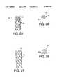
- FIG. 25is a partial perspective view on an enlarged scale of another embodiment of the flexible longitudinal rods of the device according to the invention.
- FIG. 26is an end view of the rod in FIG. 25.
- FIG. 27is a similar view to FIG. 25 of an alternative embodiment of the flexible rod.
- FIG. 28is an end view of the rod in FIG. 27.
- FIG. 1shows a spinal osteosynthesis device consisting of a lumbosacral instrumentation, extending from the sacrum S, at S1, S2 and extending over the first three lumbar vertebrae L5, L4, L3.
- This devicecomprises elements 1 for bone anchoring into the sacrum and into the lumbar vertebrae, two flexible longitudinal rods 2 with high elastic limit and small cross section, which are approximately mutually parallel and pass through the connectors (3, 4, 5, 6) to which they are fixed, and which are themselves solidly mechanically fastened to the anchoring elements 1.
- the two rods 2consist of two parallel parts of a single rod bent in hairpin fashion, which pass through the first four connectors 3, 4, 5, 6, the last being anchored in the sacrum at S1.
- the two rodsjoin to form a loop on a rounded portion of the sacral connector 7, placed at S2.
- the rods 2may be made of steel with high elastic limit, for example 650 N/mm 2 , and with high breaking strength (for example 1400 N/mm 2 ) and their diameter may be approximately 2 or 3 mm.
- the bone anchoring elements 1may either be hooks (FIGS. 2 and 3) or pedical screws (FIGS. 4 and 5).
- the pedical hook 8(FIG. 2) comprises a vertebral anchoring part consisting of the hook 9 proper, the edge of which has a notch 9a and which is connected to a mid-part 11 extended by a cylindrical body 12. At least two longitudinal slots, namely four slots 13 in the example represented, are made in this cylindrical body 12, which slots together define four radially expansible branches 14. The inner faces of these branches have an internal screw thread 15 and an annular chamfer 16 is formed on the ends of the branches 14.
- an expansion screw 17including a threaded rod 18 designed to be capable of being screwed into the body 12, and a head 19 provided with a conical surface 21.
- the lattercan bear on the chamfer 16 when the screw 17 is screwed into the internal screw threads 15, causing radial expansion of the branches 14, the external surface of which then assumes a frustoconical shape.
- the conical head 19 of the screw 17has a plane surface 37 which is bordered by the conical region 21 and in which a central impression 30 is formed, designed to receive a tightening key, not shown.
- the impression 30may be of both hexagonal and six-lobed shape.
- the laminar hook 22 in FIG. 3differs from the pedical hook 8 solely by virtue of its anchoring tip 23, which has a continuous edge.
- the pedical screw 24 in FIGS. 4 and 5includes a threaded bone anchoring rod 25 which is extended, on the side opposite its tip, by a conical part 26 which is itself followed by a cylindrical body 12 similar to the body 12 in FIGS. 2 and 3.
- a conical part 26which is itself followed by a cylindrical body 12 similar to the body 12 in FIGS. 2 and 3.
- its conical surface 21bears on the chamfer 16 while causing radial expansion of the branches 14 (FIG. 5).
- Each of the connectors 3, 4, 5, 6 represented in FIG. 1can be produced according to one of the two embodiments represented in FIGS. 6 to 10 and 24.
- the connector 3 in FIGS. 6, 8, 9 and 10comprises a base 25 with L-shaped profile, the short branch 25a of the L being extended by a protrusion 26 through which a tapped hole 27 is pierced.
- Two mutually parallel bores 31are machined in the branch 25a, which bores pass through the branch 25a on either side of the protrusion 26.
- These bores 31are circular and extend in cross section on either side of the plane of the long branch 25b of the base 25. They are extended by two semicircular parallel channels 32 which are made in the surface of the branch 25b of the L and which extend as far as the edge of the latter, through the central part of which a tapped hole 33 is pierced.
- the connector 3 (4, 5, 6)also includes a block 28 consisting of a small plate through which a central hole 29 is pierced and which can be placed bearing on the two branches of the L of the base 25.
- the connector 3is completed by a screw 34 whose threaded rod passes through the holes 29 and 33 when the block 28 is placed on the base 25.
- Two semicircular and parallel channels 35are machined on one of the faces of the block 28 and are positioned such that, when the block 28 is placed bearing on the long branch 25b of the base 25, these channels 35 are complementary to the semicircular channels 32 in order to form circular bores in which the rods 2 can be placed.
- the hole 27is dimensioned to be capable of receiving the body 12 of the anchoring element 8, 22 or 24, a pedical screw 24 being represented engaged in the hole 27 in FIGS. 9 and 10.
- the screw 17When the screw 17 is screwed into the body 12, the latter undergoes radial expansion (FIG. 5) and its branches 14 are strongly applied onto the wall of the hole 27, consequently solidly attaching the connector 3 and the anchoring element 8, 22 or 24.
- the radial expansion of the branches 14is caused by the force exerted by the conical region 21 of the screw 17 on the chamfer 16 which has the same inclination.
- the outer surface of the body 12advantageously has asperities 36 (FIG. 4) making it rough, which promotes solid attachment of the body 12 to the connector.
- a helicoid groove 20is also made in the hole 27 of the connector, in order to improve the mechanical linkage between the bone anchoring element and the connector.
- the radial forces applied onto the walls of the protrusion 26 by tightening the screw 17are symbolically represented by the arrows F in FIGS. 9 and 10.
- the connector 3adiffers from the connector 3 solely in that the bores 38 and the channels 39, 41 respectively formed on the base 25 and on the block 28 have an oblong cross section.
- the major axis of these oblong cross sectionsextends perpendicularly to the face of the branch 25b of the base 25 and to the corresponding face of the block 28.
- the oblong shape of the bores 38 and of the channels 39, 41has the advantage of increasing the inertia of the corresponding oblong rods (not represented) and therefore the bending strength in the plane passing through the axis of the anchoring and parallel to the longitudinal rods.
- the sacral fixation connector 7(FIG. 11) includes, at one of its ends, a set-back part 42 defining a rounded shoulder 43, which is preferably semicircular, extended by two parallel bores 31 which pierce entirely through the connector 7.
- the two longitudinal rods 2 passing through the bores 31are joined by a loop 2a which bears on the shoulder 43 and with which they therefore form a single longitudinal rod.
- Two bores 44are pierced, in the body of the connector 7, for receiving the sacral fixation screws, not represented, (such as 24).
- the axes XX of the bores 44are parallel and their projections into a longitudinal axial plane (P) of the connector 7 have an inclination (A) with respect to the perpendiculars to the faces of the Connector which are contained in said plane (FIGS. 12 and 14).
- the axes XXhave an inclination (B) with respect to the axial plane (P) (FIG. 12).
- the angle Amay, for example, be of the order of 15°, while B may be approximately 30°, these values being, of course, non limiting.
- the angle Bmay be oriented to the left or to the right, in order to differentiate between left sacral engagement and right sacral engagement.
- the bores 44allow looping over the rounded part 43 of the flexible linkage elements 2.
- This mountingmakes it possible to stabilize and arthrodese the region of the spine consisting of the lumbar vertebrae and the sacrum, essentially S1 and S2. It is fitted using pedical screws 24, in the case of the lumbar region and the vertebra S1, and sacral screws 24 in the case of the vertebra S2. These screws constitute the bone anchorings, the sacral screws being bone-screws having a diameter of, for example, 3.5 mm, commonly used in orthopedic surgery.
- the longitudinal rods 2actually consist, as already indicated, of a single rod looped over the sacral connector 7, the two branches of the loop 2a which consist of the rods 2 then being threaded into the connectors 3, 4, 5, 6.
- the entire instrumentationis solidly attached to the spine by the pedical screws and sacral screws at S2.
- the entire devicecan be bent in order to make its curvature coincide with the curvature of the spine.
- the deviceis bilateral, only the right-hand side being represented in FIG. 1.
- the surgical technique for fitting the deviceis as follows.
- the screwed implants or anchoringsare first fitted by the pedicals and in S1.
- the screwsare implanted "right in front” or more laterally on the root of the transverse structure, so as to make the two pedical screws on the same vertebra converge.
- the sacral fixation connector 7 and the connectors 3, 4 . . . for the pedical screws and the screw of S1are fitted on the flexible linkage elements 2.
- the blocks 28are not clamped, in order to allow them to be adjusted as a function of the gaps from vertebra to vertebra, or from pedical screw to pedical screw and allow great flexibility.
- the assembly of flexible longitudinal elements 2 and connectors 3 . . .is then bent to match the curvature of the spine (lordosis or kyphosis). Insertion is then carried out by threading the connectors over the screw heads 24.
- the expansion screws 17are tightened as the flexible rod 2/connectors 3, 4 . . . assembly is introduced, the operation being carried out starting from the functional element situated uppermost on the spine, towards the sacrum. Once the assembly of connectors has been introduced and locked in the screw heads, the sacral screws of S2 are fitted in the specific sacral connector 7.
- the opposite sideis equipped identically.
- the maneuvers for reduction or correctionare then carried out stage by stage, with the respective blocks being locked.
- This maneuveris carried out, starting from the sacrum, unilaterally or bilaterally by moving the connectors together or apart using suitable ancillary equipment.
- the graftsare then placed between the various spaces left by the instrumentation in order to carry out the arthrodesis.
- the screw 48 represented in FIG. 15is particularly suited to certain pathologies of the spine, such as spondylolisthesis, spondylolysis.
- the rod 51is designed to receive a nut 53, optionally provided with a widened bearing surface 54.
- the screw 48is used with a connector such as 3, 4 . . . or a double connector plate 61 (FIGS. 20-21) which will be described hereinbelow.
- anterior instrumentationCertain pathologies of the spine justify the use of instrumentation for anterior operation, called anterior instrumentation.
- the device according to the inventionis compatible with this type of operation and fitting. However, it is then advantageously supplemented by anterior bearing plates 55a or 55b (FIGS. 16 and 17) which makes it possible to prevent the corresponding body screws 24 from being driven in (FIG. 19) and to obtain better alignment of the connectors 3, 4, 5, 6 (the device having no sacral fixation connector 7 in this use).
- the vertebral bodyhas a concavity on its periphery which sometimes makes it difficult to fit the equipment.
- Weak strength of the peripheral corticalalso justifies widening the bearing zone on the body and avoiding direct contact of the cone 26 of the screw 24.
- each bearing plate 55is provided with conical spikes 56 which may or may not be ribbed, which position it and stabilize it until the body screw 24 is fitted.
- Each plate 55is pierced with a central hole 57 for passing the body screw 24.
- the plate 55is either rigid (plate 55a in FIG. 15), and thereby of sufficient thickness, with a shaped part 58 matched to the concavity of the vertebra, or flexible (plate 55b in FIG. 16) and, in this case, thinner than the plate 55a, in order to be capable of matching the concavity of the vertebra.
- the double connector 61comprises two plates 62 and 63. These two plates are suitably bent in order to respect the anatomical curvature of the patient, and each include an end block 65 fitted with a clamping element (screw) 66 which makes it possible, in a manner similar to what was described hereinabove, to block the flexible rods 2 in their bores 67 which are made in the base 68 for supporting the respective blocks 65.
- these bases 68are each pierced with a hole 69 for passing the threaded rod of the blocking screw 66, in addition to the holes 64 for passing the rods of the bone anchoring screws 24.
- Each plate 62, 63further comprises a respective elongate end part 71, 72, connected to the end base 68 by a link 73, 74.
- the latterhas a recess 75 allowing the end 72 to be applied onto the surface of the end 71 of the plate 62.
- An oblong hole 76is arranged in the end 72 and at least one hole 77 (two holes 77 in the example represented) is or are made in the elongate end 71, so that the oblong hole 76 can be placed opposite the holes 77.
- the two plates 62 and 63can thus be assembled using two screws 78 passing through the oblong hole 76 and the holes 77 to block the two plates on one another (FIG. 20).
- Asperitiesare formed on the surfaces of the plates 62, 63 which bear on each other, that is to say the elongate end surfaces 71 and 72. In the example described, these asperities consist of serrations 79 formed around the oblong hole 76 and the holes 77.
- the oblong hole 76makes it possible to adjust the relative position of the two plates 62, 63, and the asperities 79 provide the relative stability of the two plates in translation and in rotation.
- a mixed mountingis then obtained which has increased rigidity in the fracture center, by virtue of the double connector 61, and is more elastic on either side of the center, which ensures global stability of the spine.
- FIGS. 25 and 26illustrate another embodiment of the longitudinal flexible rods, here each consisting not of a solid rod such as 2, but of an assembly of filaments 85 forming a strand 86.
- the strand 86is thus produced by assembling 7 filaments 85, and may be of reduced diameter.
- the rods or strands 86should take up the tensile and compressive forces and allow some degree of flexibility for taking up the displacements imposed on them.
- the use of a strand or of a solid rodcan improve the bending fatigue strength of the longitudinal element.
- the rod 86may have a diameter of, for example, 2 mm or 2.5 mm. It is clear that a strand, for example of 7 filaments, will have reduced filament diameters, which will give it great flexibility.
- the strand 87consists of an assembly of 7 filaments 88 (one central filament and six peripheral filaments) which are redrawn in order to increase the metal cross section and the rigidity of the strand.
- the strands 86, 87may include a variable number of filaments, and be made, for example, of stainless steel 316 L with high elastic limit.
- This devicecan be used in posterior or anterior operation.
- the assembly of rods and connectorsby virtue of the flexibility of these rods, makes it possible to adapt with ease and without constraint to any positioning of the bone anchoring elements.
- the sliding of the connectors over the rods after fixing of the bone anchoring elements theretomakes it possible to refine the reduction of the instrumented spinal segment. Fixing the connectors onto the rods by clamping rigidifies the assembly whilst retaining some degree of elasticity for the instrumentation by virtue of the mechanical characteristics of the rods, thus promoting taking of the bone graft associated with osteosynthesis.
- the vertebral screwsmay be introduced before the linkage elements or through them.
Landscapes
- Health & Medical Sciences (AREA)
- Orthopedic Medicine & Surgery (AREA)
- Life Sciences & Earth Sciences (AREA)
- Surgery (AREA)
- Neurology (AREA)
- Heart & Thoracic Surgery (AREA)
- Engineering & Computer Science (AREA)
- Biomedical Technology (AREA)
- Nuclear Medicine, Radiotherapy & Molecular Imaging (AREA)
- Medical Informatics (AREA)
- Molecular Biology (AREA)
- Animal Behavior & Ethology (AREA)
- General Health & Medical Sciences (AREA)
- Public Health (AREA)
- Veterinary Medicine (AREA)
- Surgical Instruments (AREA)
- Prostheses (AREA)
Abstract
Description
Claims (25)
Applications Claiming Priority (3)
| Application Number | Priority Date | Filing Date | Title |
|---|---|---|---|
| FR9204449AFR2689750B1 (en) | 1992-04-10 | 1992-04-10 | BONE ANCHORING ELEMENT AND SPINAL OSTEOSYNTHESIS DEVICE INCORPORATING SUCH ELEMENTS. |
| FR9204449 | 1992-04-10 | ||
| PCT/FR1993/000366WO1993020771A1 (en) | 1992-04-10 | 1993-04-09 | Spinal osteosynthesis device |
Publications (1)
| Publication Number | Publication Date |
|---|---|
| US5704936Atrue US5704936A (en) | 1998-01-06 |
Family
ID=9428750
Family Applications (1)
| Application Number | Title | Priority Date | Filing Date |
|---|---|---|---|
| US08/318,654Expired - Fee RelatedUS5704936A (en) | 1992-04-10 | 1993-04-09 | Spinal osteosynthesis device |
Country Status (9)
| Country | Link |
|---|---|
| US (1) | US5704936A (en) |
| EP (1) | EP0634911B1 (en) |
| JP (1) | JP2642516B2 (en) |
| AU (1) | AU661904B2 (en) |
| CA (1) | CA2133766C (en) |
| DE (1) | DE69314334T2 (en) |
| ES (1) | ES2109488T3 (en) |
| FR (1) | FR2689750B1 (en) |
| WO (1) | WO1993020771A1 (en) |
Cited By (218)
| Publication number | Priority date | Publication date | Assignee | Title |
|---|---|---|---|---|
| US5928243A (en) | 1997-07-16 | 1999-07-27 | Spinal Concepts, Inc. | Pedicle probe and depth gage |
| US5935133A (en) | 1997-08-26 | 1999-08-10 | Spinal Concepts, Inc. | Surgical cable system and method |
| US5989250A (en) | 1996-10-24 | 1999-11-23 | Spinal Concepts, Inc. | Method and apparatus for spinal fixation |
| US6030389A (en) | 1997-08-04 | 2000-02-29 | Spinal Concepts, Inc. | System and method for stabilizing the human spine with a bone plate |
| US6045579A (en) | 1997-05-01 | 2000-04-04 | Spinal Concepts, Inc. | Adjustable height fusion device |
| US6053921A (en) | 1997-08-26 | 2000-04-25 | Spinal Concepts, Inc. | Surgical cable system and method |
| US6132430A (en) | 1996-10-24 | 2000-10-17 | Spinal Concepts, Inc. | Spinal fixation system |
| WO2000064364A1 (en)* | 1999-04-23 | 2000-11-02 | Sdgi Holdings, Inc. | Tethering device for fusionless spinal deformity correction |
| US6248106B1 (en) | 2000-02-25 | 2001-06-19 | Bret Ferree | Cross-coupled vertebral stabilizers |
| WO2001054599A1 (en)* | 2000-01-31 | 2001-08-02 | Sven Olerud | Locking device and method for using this device |
| US6331179B1 (en) | 2000-01-06 | 2001-12-18 | Spinal Concepts, Inc. | System and method for stabilizing the human spine with a bone plate |
| GR1003754B (en)* | 2000-09-22 | 2002-01-15 | Χρηστος Καλαιτζης | Transpedicular screw/rod/ligament system for posterior spinal arthrodesis |
| US20020058939A1 (en)* | 1997-08-04 | 2002-05-16 | Spinal Concepts, Inc. | System and method for stabilizing the human spine with a bone plate |
| US6423065B2 (en) | 2000-02-25 | 2002-07-23 | Bret A. Ferree | Cross-coupled vertebral stabilizers including cam-operated cable connectors |
| US20020107573A1 (en)* | 1999-03-07 | 2002-08-08 | Discure Ltd. | Method and apparatus for computerized surgery |
| US20020120268A1 (en)* | 2001-02-21 | 2002-08-29 | Roger Berger | Occipital plate and system for spinal stabilization |
| US20020133155A1 (en)* | 2000-02-25 | 2002-09-19 | Ferree Bret A. | Cross-coupled vertebral stabilizers incorporating spinal motion restriction |
| US20020138077A1 (en)* | 2001-03-26 | 2002-09-26 | Ferree Bret A. | Spinal alignment apparatus and methods |
| US6554831B1 (en) | 2000-09-01 | 2003-04-29 | Hopital Sainte-Justine | Mobile dynamic system for treating spinal disorder |
| US20030114853A1 (en)* | 2001-10-12 | 2003-06-19 | Ian Burgess | Polyaxial cross connector |
| US6582434B2 (en)* | 2000-05-10 | 2003-06-24 | Showa Ika Kohgyo Co., Ltd. | Vertebral connecting rod and spinal osteosynthesis device using the same |
| US6599290B2 (en) | 2001-04-17 | 2003-07-29 | Ebi, L.P. | Anterior cervical plating system and associated method |
| US20030204259A1 (en)* | 2000-12-13 | 2003-10-30 | Goble E. Marlowe | Multiple facet joint replacement |
| US20040049188A1 (en)* | 2002-09-09 | 2004-03-11 | Depuy Acromed, Inc. | Snap-on spinal rod connector |
| US20040087953A1 (en)* | 2002-05-15 | 2004-05-06 | Wamis Singhatat | Cross-pin graft fixation, instruments, and methods |
| US20040133207A1 (en)* | 2002-10-11 | 2004-07-08 | Abdou M. Samy | Distraction screw for skeletal surgery and method of use |
| US20040204713A1 (en)* | 2003-01-10 | 2004-10-14 | Abdou M. Samy | Plating system for bone fixation and subsidence and method of implantation |
| US20040215191A1 (en)* | 2003-04-25 | 2004-10-28 | Kitchen Michael S. | Spinal curvature correction device |
| US20040236327A1 (en)* | 2003-05-23 | 2004-11-25 | Paul David C. | Spine stabilization system |
| US20040260397A1 (en)* | 1999-08-18 | 2004-12-23 | Lambrecht Greg H. | Method of defect closure in anulus fibrosus |
| US20050033298A1 (en)* | 2001-10-31 | 2005-02-10 | Ortho Development Corporation | Cervical plate for stabilizing the human spine |
| US20050033440A1 (en)* | 1999-08-18 | 2005-02-10 | Lambrecht Gregory H. | Intervertebral disc implant resistant to migration |
| US6872210B2 (en) | 2001-02-23 | 2005-03-29 | James P. Hearn | Sternum fixation device |
| US20050113922A1 (en)* | 2002-07-26 | 2005-05-26 | Edinowa Pty Ltd | Spinal implant |
| US20050131409A1 (en)* | 2003-12-10 | 2005-06-16 | Alan Chervitz | Linked bilateral spinal facet implants and methods of use |
| FR2867057A1 (en)* | 2004-03-02 | 2005-09-09 | Spinevision | Connecting element, useful for a spinal fixing system to connect two entire implantable connection bodies comprises a cable and a polymer envelope surrounding the cable |
| US20050202370A1 (en)* | 2001-12-28 | 2005-09-15 | Nobel Biocare Ab | Implant arrangement and device |
| US20050216027A1 (en)* | 2004-03-24 | 2005-09-29 | Suh Sean S | Extraction screwdriver |
| US20050216004A1 (en)* | 2004-03-23 | 2005-09-29 | Schwab Frank J | Device and method for dynamic spinal fixation for correction of spinal deformities |
| US20050228326A1 (en)* | 2004-03-31 | 2005-10-13 | Depuy Spine, Inc. | Head-to-head connector spinal fixation system |
| US20050228386A1 (en)* | 2004-04-08 | 2005-10-13 | Tara Ziolo | Bone fixation device |
| US20050228377A1 (en)* | 2004-04-07 | 2005-10-13 | Depuy Spine, Inc. | Spinal cross-connectors |
| US20050234551A1 (en)* | 2001-03-02 | 2005-10-20 | Facet Solutions, Inc. | Method and apparatus for spine joint replacement |
| US20050277920A1 (en)* | 2004-05-28 | 2005-12-15 | Slivka Michael A | Non-fusion spinal correction systems and methods |
| US20060036246A1 (en)* | 2004-08-03 | 2006-02-16 | Carl Allen L | Device and method for correcting a spinal deformity |
| US20060058789A1 (en)* | 2004-08-27 | 2006-03-16 | Depuy Spine, Inc. | Dual rod cross connectors and inserter tools |
| US20060058792A1 (en)* | 2004-09-16 | 2006-03-16 | Hynes Richard A | Intervertebral support device with bias adjustment and related methods |
| US20060064091A1 (en)* | 2004-03-31 | 2006-03-23 | Depuy Spine, Inc. | Rod attachment for head to head cross connector |
| US7041136B2 (en) | 2000-11-29 | 2006-05-09 | Facet Solutions, Inc. | Facet joint replacement |
| US20060149238A1 (en)* | 2005-01-04 | 2006-07-06 | Sherman Michael C | Systems and methods for spinal stabilization with flexible elements |
| US20060149251A1 (en)* | 2004-12-22 | 2006-07-06 | Tara Ziolo | Bone fixation system |
| US20060161157A1 (en)* | 2004-02-26 | 2006-07-20 | Lawrence Mosca | Bone plate system and methods |
| US20060167456A1 (en)* | 2004-12-21 | 2006-07-27 | Packaging Service Corporation Of Kentucky | Cervical plate system |
| WO2006079531A1 (en)* | 2005-01-26 | 2006-08-03 | Aesculap Ag & Co. Kg | Self-contouring spinal rod |
| US20060173454A1 (en)* | 2003-10-21 | 2006-08-03 | Innovative Spinal Technologies | Internal structure stabilization system for spanning three or more structures |
| US20060189984A1 (en)* | 2005-02-22 | 2006-08-24 | Medicinelodge, Inc. | Apparatus and method for dynamic vertebral stabilization |
| US20060200149A1 (en)* | 2005-02-22 | 2006-09-07 | Hoy Robert W | Polyaxial orhtopedic fastening apparatus |
| US20060200246A1 (en)* | 1999-08-18 | 2006-09-07 | Lambrecht Gregory H | Method of monitoring characteristics of an intervertebral disc and implantable prosthetic |
| US20060217715A1 (en)* | 2005-03-24 | 2006-09-28 | Depuy Spine, Inc. | Low profile spinal tethering systems |
| US20060217718A1 (en)* | 2005-03-28 | 2006-09-28 | Facet Solutions, Inc. | Facet joint implant crosslinking apparatus and method |
| US20060217717A1 (en)* | 2005-03-24 | 2006-09-28 | Dale Whipple | Methods and devices for stabilizing a bone anchor |
| US20060235407A1 (en)* | 2001-11-09 | 2006-10-19 | Wang Robert C | Apparatus and methods for bone fracture reduction and fixation |
| US20060235408A1 (en)* | 2001-11-09 | 2006-10-19 | Wang Robert C | Apparatus and methods for bone fracture fixation |
| US20060264942A1 (en)* | 2004-01-30 | 2006-11-23 | Roy Lim | Instruments and methods for minimally invasive spinal stabilization |
| US20060271045A1 (en)* | 2005-05-27 | 2006-11-30 | Depuy Spine, Inc. | Spinal cross-connector |
| US20070005063A1 (en)* | 2005-06-20 | 2007-01-04 | Sdgi Holdings, Inc. | Multi-level multi-functional spinal stabilization systems and methods |
| US20070016296A1 (en)* | 2004-06-02 | 2007-01-18 | Triplett Daniel J | Surgical measurement systems and methods |
| US20070067039A1 (en)* | 1999-08-18 | 2007-03-22 | Lambrecbt Greg H | Intervertebral disc herniation repair |
| US20070083207A1 (en)* | 2005-09-21 | 2007-04-12 | Tara Ziolo | Variable angle bone fixation assembly |
| US20070123879A1 (en)* | 2003-02-05 | 2007-05-31 | Pioneer Laboratories, Inc. | Bone plate system |
| US20070123887A1 (en)* | 2004-04-07 | 2007-05-31 | Hubert Hirt | Instrument Set For Fixing An Implant In A Bone |
| US20070191953A1 (en)* | 2006-01-27 | 2007-08-16 | Sdgi Holdings, Inc. | Intervertebral implants and methods of use |
| US20070191841A1 (en)* | 2006-01-27 | 2007-08-16 | Sdgi Holdings, Inc. | Spinal rods having different flexural rigidities about different axes and methods of use |
| US20070191837A1 (en)* | 2006-01-27 | 2007-08-16 | Sdgi Holdings, Inc. | Interspinous devices and methods of use |
| US20070191832A1 (en)* | 2006-01-27 | 2007-08-16 | Sdgi Holdings, Inc. | Vertebral rods and methods of use |
| US20070203493A1 (en)* | 1997-01-02 | 2007-08-30 | Zucherman James F | Spine distraction implant and method |
| US20070233094A1 (en)* | 2006-03-29 | 2007-10-04 | Dennis Colleran | Dynamic motion spinal stabilization system |
| US20070233068A1 (en)* | 2006-02-22 | 2007-10-04 | Sdgi Holdings, Inc. | Intervertebral prosthetic assembly for spinal stabilization and method of implanting same |
| US20070270837A1 (en)* | 2006-05-08 | 2007-11-22 | Sdgi Holdings, Inc. | Load bearing flexible spinal connecting element |
| US20070270838A1 (en)* | 2006-05-08 | 2007-11-22 | Sdgi Holdings, Inc. | Dynamic spinal stabilization device with dampener |
| US20070270836A1 (en)* | 2006-05-08 | 2007-11-22 | Sdgi Holdings, Inc. | Dynamic spinal stabilization members and methods |
| US20070270839A1 (en)* | 2006-04-05 | 2007-11-22 | Dong Myung Jeon | Multi-axial double locking bone screw assembly |
| US20080033433A1 (en)* | 2006-08-01 | 2008-02-07 | Dante Implicito | Dynamic spinal stabilization device |
| US20080097432A1 (en)* | 2006-09-27 | 2008-04-24 | Depuy Products, Inc. | Flexible bone fixation device |
| US20080140123A1 (en)* | 2006-11-28 | 2008-06-12 | Ferree Bret A | Methods and apparatus for stabilizing a spinal segment |
| US20080153067A1 (en)* | 2005-10-24 | 2008-06-26 | Biomet 3I, Inc. | Methods for placing an implant analog in a physical model of the patient's mouth |
| US20080167688A1 (en)* | 2005-02-22 | 2008-07-10 | Facet Solutions, Inc. | Taper-Locking Fixation System |
| WO2008045424A3 (en)* | 2006-10-06 | 2008-07-17 | Poly 5 Group Llc | Bone bridge providing dynamic compression on bone fractures |
| US20080177318A1 (en)* | 2007-01-18 | 2008-07-24 | Warsaw Orthopedic, Inc. | Vertebral Stabilizer |
| US20080183212A1 (en)* | 2007-01-30 | 2008-07-31 | Warsaw Orthopedic, Inc. | Dynamic Spinal Stabilization Assembly with Sliding Collars |
| US20080183223A1 (en)* | 2005-09-26 | 2008-07-31 | Jeon Dong M | Hybrid jointed bone screw system |
| US20080183213A1 (en)* | 2007-01-30 | 2008-07-31 | Warsaw Orthopedic, Inc. | Collar Bore Configuration for Dynamic Spinal Stabilization Assembly |
| US20080195151A1 (en)* | 2007-02-13 | 2008-08-14 | Ferree Bret A | Methods of Bone, Joint, and Ligament Reconstruction |
| EP1958580A1 (en) | 2007-02-13 | 2008-08-20 | DePuy Products, Inc. | Orthopaedic trauma bone plate kit |
| US20080221622A1 (en)* | 2007-01-10 | 2008-09-11 | Facet Solutions, Inc. | Facet Joint Replacement |
| US20080286722A1 (en)* | 2007-05-18 | 2008-11-20 | Biomet 3I, Inc. | Method for selecting implant components |
| US20090012571A1 (en)* | 2007-07-03 | 2009-01-08 | Pioneer Surgical Technology, Inc. | Bone Plate System |
| US20090012565A1 (en)* | 2007-06-06 | 2009-01-08 | Vertech, Inc. | Medical device and method to correct deformity |
| US20090018583A1 (en)* | 2007-07-12 | 2009-01-15 | Vermillion Technologies, Llc | Dynamic spinal stabilization system incorporating a wire rope |
| US20090024169A1 (en)* | 2004-06-02 | 2009-01-22 | Facet Solutions, Inc. | System and method for multiple level facet joint arthroplasty and fusion |
| US20090024166A1 (en)* | 2004-08-03 | 2009-01-22 | Vertech Innovations, Llc. | Facet device and method |
| US20090062862A1 (en)* | 2007-07-03 | 2009-03-05 | Pioneer Surgical Technology, Inc. | Bone Plate System |
| US20090069851A1 (en)* | 2007-07-19 | 2009-03-12 | Acumed Llc | Bone fixation with slender spanning members disposed outside bone |
| US20090130630A1 (en)* | 2007-11-16 | 2009-05-21 | Suttin Zachary B | Components for Use with a Surgical Guide for Dental Implant Placement |
| US20090143823A1 (en)* | 2008-11-13 | 2009-06-04 | Jeon Dong M | Transverse connector system for spinal rods |
| WO2009049161A3 (en)* | 2007-10-12 | 2009-06-25 | Synthes Usa | Reconstruction device |
| US20090163955A1 (en)* | 2007-12-19 | 2009-06-25 | Missoum Moumene | Polymeric Pedicle Rods and Methods of Manufacturing |
| US20090171395A1 (en)* | 2007-12-28 | 2009-07-02 | Jeon Dong M | Dynamic spinal rod system |
| US7566345B1 (en) | 2001-03-01 | 2009-07-28 | Facet Solutions, Inc | Prosthesis for the replacement of a posterior element of a vertebra |
| US20090192548A1 (en)* | 2008-01-25 | 2009-07-30 | Jeon Dong M | Pedicle-laminar dynamic spinal stabilization device |
| US20090194206A1 (en)* | 2008-01-31 | 2009-08-06 | Jeon Dong M | Systems and methods for wrought nickel/titanium alloy flexible spinal rods |
| US7588588B2 (en) | 2003-10-21 | 2009-09-15 | Innovative Spinal Technologies | System and method for stabilizing of internal structures |
| US20090248079A1 (en)* | 2008-03-26 | 2009-10-01 | Kwak Seungkyu Daniel | S-Shaped Interspinous Process Spacer Having Tight Access Offset Hooks |
| US20090248076A1 (en)* | 2008-03-26 | 2009-10-01 | Reynolds Martin A | Interspinous Process Spacer Having Tight Access Offset Hooks |
| US20090264933A1 (en)* | 2008-04-22 | 2009-10-22 | Warsaw Orthopedic, Inc. | Anchors for securing a rod to a vertebral member |
| US20090263764A1 (en)* | 2008-04-16 | 2009-10-22 | Biomet 3I, Llc | Method for pre-operative visualization of instrumentation used with a surgical guide for dental implant placement |
| US20090275986A1 (en)* | 2008-05-05 | 2009-11-05 | Warsaw Orthopedic, Inc. | Flexible spinal stabilization element and system |
| US20090287251A1 (en)* | 2008-05-13 | 2009-11-19 | Stryker Spine | Composite spinal rod |
| US20090318967A1 (en)* | 2007-01-23 | 2009-12-24 | Dong Myung Jeon | Spacer for use in a surgical operation for spinous process of spine |
| US7637952B2 (en) | 2002-03-11 | 2009-12-29 | Zimmer Spine, Inc. | Instrumentation and procedure for implanting spinal implant devices |
| US20090326584A1 (en)* | 2008-06-27 | 2009-12-31 | Michael Andrew Slivka | Spinal Dynamic Stabilization Rods Having Interior Bumpers |
| US20090326583A1 (en)* | 2008-06-25 | 2009-12-31 | Missoum Moumene | Posterior Dynamic Stabilization System With Flexible Ligament |
| US20100004664A1 (en)* | 2005-12-28 | 2010-01-07 | Intrinsic Therapeutics, Inc. | Anchoring system for disc repair |
| US20100049256A1 (en)* | 2007-01-30 | 2010-02-25 | Dong Myung Jeon | Anterior cerivcal plating system |
| US20100049259A1 (en)* | 2007-09-07 | 2010-02-25 | Intrinsic Therapeutics, Inc. | Method for vertebral endplate reconstruction |
| US20100076448A1 (en)* | 2003-12-29 | 2010-03-25 | Abdou M Samy | Plating system for bone fixation and method of implantation |
| US20100087865A1 (en)* | 2008-10-08 | 2010-04-08 | Lutz Biedermann | Bone anchoring device and stabilization device for bone parts or vertebrae comprising such a bone anchoring device |
| US20100094344A1 (en)* | 2008-10-14 | 2010-04-15 | Kyphon Sarl | Pedicle-Based Posterior Stabilization Members and Methods of Use |
| US20100094294A1 (en)* | 2008-10-10 | 2010-04-15 | Joel Gillard | Cerclage system for bone |
| US20100121384A1 (en)* | 2004-06-14 | 2010-05-13 | Abdou M Samy | Occipital fixation system and method of use |
| US20100121455A1 (en)* | 2007-09-07 | 2010-05-13 | Intrinsic Therapeutics, Inc. | Soft tissue impaction methods |
| US7722647B1 (en) | 2005-03-14 | 2010-05-25 | Facet Solutions, Inc. | Apparatus and method for posterior vertebral stabilization |
| US20100161056A1 (en)* | 2008-12-19 | 2010-06-24 | Depuy Spine, Inc. | Methods and devices for expanding a spinal canal |
| US20100204797A1 (en)* | 1999-08-18 | 2010-08-12 | Intrinsic Therapeutics, Inc. | Anulus lesion repair |
| US20100211104A1 (en)* | 2009-02-13 | 2010-08-19 | Missoum Moumene | Dual Spring Posterior Dynamic Stabilization Device With Elongation Limiting Elastomers |
| US20100249837A1 (en)* | 2009-03-26 | 2010-09-30 | Kspine, Inc. | Semi-constrained anchoring system |
| US20100268278A1 (en)* | 2009-04-15 | 2010-10-21 | Warsaw Orthopedic, Inc. | Tension band |
| US7833251B1 (en) | 2004-01-06 | 2010-11-16 | Nuvasive, Inc. | System and method for performing spinal fixation |
| US20100298837A1 (en)* | 2003-06-20 | 2010-11-25 | Intrinsic Therapeutics, Inc. | Methods for delivering an implant and agent in an intervertebral disc |
| US20100312282A1 (en)* | 2005-02-18 | 2010-12-09 | Samy Abdou | Devices and methods for dynamic fixation of skeletal structure |
| US20100318129A1 (en)* | 2009-06-16 | 2010-12-16 | Kspine, Inc. | Deformity alignment system with reactive force balancing |
| US7854752B2 (en) | 2004-08-09 | 2010-12-21 | Theken Spine, Llc | System and method for dynamic skeletal stabilization |
| US20100331886A1 (en)* | 2009-06-25 | 2010-12-30 | Jonathan Fanger | Posterior Dynamic Stabilization Device Having A Mobile Anchor |
| US20110054536A1 (en)* | 2008-11-11 | 2011-03-03 | Kspine, Inc. | Growth directed vertebral fixation system with distractible connector(s) and apical control |
| US20110054535A1 (en)* | 2009-08-28 | 2011-03-03 | Gephart Matthew P | Size Transition Spinal Rod |
| US20110066188A1 (en)* | 2009-09-15 | 2011-03-17 | Kspine, Inc. | Growth modulation system |
| US20110071570A1 (en)* | 2009-09-24 | 2011-03-24 | Warsaw Orthopedic, Inc. | Composite vertebral rod system and methods of use |
| US20110106087A1 (en)* | 2009-10-30 | 2011-05-05 | Gamache Thomas J | Bone Plate Holder |
| US20110106169A1 (en)* | 2009-10-30 | 2011-05-05 | Zalenski Edward B | Bone Plate Holder |
| US20110106083A1 (en)* | 2009-10-30 | 2011-05-05 | Voellmicke John C | Laminoplasty Plates and Methods of Expanding the Spinal Canal |
| US20110106084A1 (en)* | 2009-10-30 | 2011-05-05 | Thomas J Gamache | Bone Graft Loading Instruments and Methods of Connecting a Bone Graft to a Bone Plate |
| US20110112537A1 (en)* | 2009-10-09 | 2011-05-12 | Acute Innovations, Llc | System for tensioning a surgical wire |
| US20110129792A1 (en)* | 2008-04-15 | 2011-06-02 | Berckmans Iii Bruce | Method of creating an accurate bone and soft-tissue digital dental model |
| US7967826B2 (en) | 2003-10-21 | 2011-06-28 | Theken Spine, Llc | Connector transfer tool for internal structure stabilization systems |
| US20110183289A1 (en)* | 2005-06-30 | 2011-07-28 | Implant Innovations, Inc. | Method For Manufacting Dental Implant Components |
| US20110238119A1 (en)* | 2010-03-24 | 2011-09-29 | Missoum Moumene | Composite Material Posterior Dynamic Stabilization Spring Rod |
| US20110238115A1 (en)* | 2010-03-23 | 2011-09-29 | Scapa Flow, Llc | Cervical link system |
| US8066750B2 (en) | 2006-10-06 | 2011-11-29 | Warsaw Orthopedic, Inc | Port structures for non-rigid bone plates |
| US8109973B2 (en) | 2005-10-31 | 2012-02-07 | Stryker Spine | Method for dynamic vertebral stabilization |
| US8118840B2 (en) | 2009-02-27 | 2012-02-21 | Warsaw Orthopedic, Inc. | Vertebral rod and related method of manufacture |
| US8328807B2 (en) | 2008-07-09 | 2012-12-11 | Icon Orthopaedic Concepts, Llc | Ankle arthrodesis nail and outrigger assembly |
| US8357181B2 (en) | 2005-10-27 | 2013-01-22 | Warsaw Orthopedic, Inc. | Intervertebral prosthetic device for spinal stabilization and method of implanting same |
| US8361117B2 (en) | 2006-11-08 | 2013-01-29 | Depuy Spine, Inc. | Spinal cross connectors |
| US8414584B2 (en) | 2008-07-09 | 2013-04-09 | Icon Orthopaedic Concepts, Llc | Ankle arthrodesis nail and outrigger assembly |
| US8480715B2 (en) | 2007-05-22 | 2013-07-09 | Zimmer Spine, Inc. | Spinal implant system and method |
| US8556936B2 (en) | 2000-11-29 | 2013-10-15 | Gmedelaware 2 Llc | Facet joint replacement |
| US8882508B2 (en) | 2010-12-07 | 2014-11-11 | Biomet 3I, Llc | Universal scanning member for use on dental implant and dental implant analogs |
| US8900277B2 (en) | 2004-02-26 | 2014-12-02 | Pioneer Surgical Technology, Inc. | Bone plate system |
| US8920472B2 (en) | 2011-11-16 | 2014-12-30 | Kspine, Inc. | Spinal correction and secondary stabilization |
| US8926328B2 (en) | 2012-12-27 | 2015-01-06 | Biomet 3I, Llc | Jigs for placing dental implant analogs in models and methods of doing the same |
| US8944818B2 (en) | 2011-05-16 | 2015-02-03 | Biomet 3I, Llc | Temporary abutment with combination of scanning features and provisionalization features |
| US8992579B1 (en) | 2011-03-08 | 2015-03-31 | Nuvasive, Inc. | Lateral fixation constructs and related methods |
| US20150164498A1 (en)* | 2013-12-11 | 2015-06-18 | Arthrex, Inc. | Suture washer |
| US9060815B1 (en) | 2012-03-08 | 2015-06-23 | Nuvasive, Inc. | Systems and methods for performing spine surgery |
| US9060813B1 (en) | 2008-02-29 | 2015-06-23 | Nuvasive, Inc. | Surgical fixation system and related methods |
| US20150201973A1 (en)* | 2014-01-23 | 2015-07-23 | Warsaw Orthopedic, Inc. | Spinal correction system and method |
| US9089382B2 (en) | 2012-01-23 | 2015-07-28 | Biomet 3I, Llc | Method and apparatus for recording spatial gingival soft tissue relationship to implant placement within alveolar bone for immediate-implant placement |
| US9198696B1 (en) | 2010-05-27 | 2015-12-01 | Nuvasive, Inc. | Cross-connector and related methods |
| US9211153B2 (en) | 2011-01-04 | 2015-12-15 | DePuy Synthes Products, Inc. | Expansion screw bone tamp |
| DE102006055599B4 (en)* | 2006-11-24 | 2016-01-07 | Peter Brehm | Orthopedic fastening device and device for correcting spinal deformity |
| US9241748B2 (en) | 2012-04-30 | 2016-01-26 | Acute Innovations Llc | System for binding bone |
| US9247964B1 (en) | 2011-03-01 | 2016-02-02 | Nuasive, Inc. | Spinal Cross-connector |
| US9333009B2 (en) | 2011-06-03 | 2016-05-10 | K2M, Inc. | Spinal correction system actuators |
| US9387013B1 (en) | 2011-03-01 | 2016-07-12 | Nuvasive, Inc. | Posterior cervical fixation system |
| CN105832434A (en)* | 2015-01-14 | 2016-08-10 | 山西医科大学 | Guiding apparatus for positioning hole distance and paralleling implants in dental implant operation |
| US9451987B2 (en) | 2011-11-16 | 2016-09-27 | K2M, Inc. | System and method for spinal correction |
| US9452032B2 (en) | 2012-01-23 | 2016-09-27 | Biomet 3I, Llc | Soft tissue preservation temporary (shell) immediate-implant abutment with biological active surface |
| US9468469B2 (en) | 2011-11-16 | 2016-10-18 | K2M, Inc. | Transverse coupler adjuster spinal correction systems and methods |
| US9468468B2 (en) | 2011-11-16 | 2016-10-18 | K2M, Inc. | Transverse connector for spinal stabilization system |
| US9468471B2 (en) | 2013-09-17 | 2016-10-18 | K2M, Inc. | Transverse coupler adjuster spinal correction systems and methods |
| US9517089B1 (en) | 2013-10-08 | 2016-12-13 | Nuvasive, Inc. | Bone anchor with offset rod connector |
| US9668834B2 (en) | 2013-12-20 | 2017-06-06 | Biomet 3I, Llc | Dental system for developing custom prostheses through scanning of coded members |
| US9700390B2 (en) | 2014-08-22 | 2017-07-11 | Biomet 3I, Llc | Soft-tissue preservation arrangement and method |
| US9706947B2 (en) | 1999-08-18 | 2017-07-18 | Intrinsic Therapeutics, Inc. | Method of performing an anchor implantation procedure within a disc |
| US20170273719A1 (en)* | 2014-01-23 | 2017-09-28 | K2M, Inc. | Spinal stabilization system |
| US9867714B1 (en) | 2011-09-23 | 2018-01-16 | Samy Abdou | Spinal fixation devices and methods of use |
| US10111757B2 (en) | 2012-10-22 | 2018-10-30 | Cogent Spine, LLC | Devices and methods for spinal stabilization and instrumentation |
| US10166054B2 (en) | 2013-07-09 | 2019-01-01 | DePuy Synthes Products, Inc. | Bone fixation system |
| US10441333B2 (en) | 2004-02-16 | 2019-10-15 | Sic Brevetti S.R.L. | Method of reinforcing a sternum after a sternotomy or a sternal fracture |
| US10449018B2 (en) | 2015-03-09 | 2019-10-22 | Stephen J. Chu | Gingival ovate pontic and methods of using the same |
| US10543107B2 (en) | 2009-12-07 | 2020-01-28 | Samy Abdou | Devices and methods for minimally invasive spinal stabilization and instrumentation |
| US10548740B1 (en) | 2016-10-25 | 2020-02-04 | Samy Abdou | Devices and methods for vertebral bone realignment |
| US10695105B2 (en) | 2012-08-28 | 2020-06-30 | Samy Abdou | Spinal fixation devices and methods of use |
| US10702311B2 (en) | 2011-11-16 | 2020-07-07 | K2M, Inc. | Spinal correction and secondary stabilization |
| US10813729B2 (en) | 2012-09-14 | 2020-10-27 | Biomet 3I, Llc | Temporary dental prosthesis for use in developing final dental prosthesis |
| US20200360059A1 (en)* | 2018-01-30 | 2020-11-19 | Orthopediatrics Corp. | Segmental tensioning of spinal tethers |
| US10857003B1 (en) | 2015-10-14 | 2020-12-08 | Samy Abdou | Devices and methods for vertebral stabilization |
| US10918498B2 (en) | 2004-11-24 | 2021-02-16 | Samy Abdou | Devices and methods for inter-vertebral orthopedic device placement |
| US10973648B1 (en) | 2016-10-25 | 2021-04-13 | Samy Abdou | Devices and methods for vertebral bone realignment |
| US10980584B2 (en) | 2016-08-16 | 2021-04-20 | DePuy Synthes Products, Inc. | Bone fixation system |
| US11000322B2 (en) | 2018-09-20 | 2021-05-11 | DePuy Synthes Products, Inc. | Bone fixation system |
| US11006982B2 (en) | 2012-02-22 | 2021-05-18 | Samy Abdou | Spinous process fixation devices and methods of use |
| US11065037B2 (en)* | 2016-05-19 | 2021-07-20 | Auctus Surgical, Inc. | Spinal curvature modulation systems and methods |
| US11179248B2 (en) | 2018-10-02 | 2021-11-23 | Samy Abdou | Devices and methods for spinal implantation |
| US11219511B2 (en) | 2005-10-24 | 2022-01-11 | Biomet 3I, Llc | Methods for placing an implant analog in a physical model of the patient's mouth |
| US11331125B1 (en) | 2021-10-07 | 2022-05-17 | Ortho Inventions, Llc | Low profile rod-to-rod coupler |
| US20230110881A1 (en)* | 2004-10-26 | 2023-04-13 | P Tech, Llc | Devices and methods for stabilizing tissue and implants |
| US11877779B2 (en) | 2020-03-26 | 2024-01-23 | Xtant Medical Holdings, Inc. | Bone plate system |
Families Citing this family (21)
| Publication number | Priority date | Publication date | Assignee | Title |
|---|---|---|---|---|
| FR2709246B1 (en)* | 1993-08-27 | 1995-09-29 | Martin Jean Raymond | Dynamic implanted spinal orthosis. |
| FR2709247B1 (en)* | 1993-08-27 | 1995-09-29 | Martin Jean Raymond | Device for anchoring spinal instrumentation on a vertebra. |
| FR2709248B1 (en)* | 1993-08-27 | 1995-09-29 | Martin Jean Raymond | Ancillary equipment for placing a spinal instrumentation. |
| FR2722393B1 (en)* | 1993-08-27 | 1996-08-23 | Martin Jean Raymond | ANCILLARY MATERIAL FOR CORRECTING A VERTEBRAL DEFORMATION |
| ATE180402T1 (en)* | 1994-02-28 | 1999-06-15 | Sulzer Orthopaedie Ag | STABILIZATION OF ADJACENT BACK VERTEBRATE |
| FR2718944B1 (en)* | 1994-04-20 | 1996-08-30 | Pierre Roussouly | Orthopedic anchoring stabilization device. |
| FR2718946B1 (en)* | 1994-04-25 | 1996-09-27 | Soprane Sa | Flexible rod for lumbosacral osteosynthesis fixator. |
| ES2081766B1 (en)* | 1994-05-13 | 1996-10-01 | Bilbao Ortiz De Zarate Jose Ra | POSTERIOR CERVICAL VERTEBRAL FIXATION SYSTEM. |
| FR2720262B1 (en)* | 1994-05-31 | 1996-10-18 | Pierre Barreau | Osteosynthesis device with added coaptors. |
| FR2726459B1 (en)* | 1994-11-07 | 1998-05-07 | Desauge Jean Pierre | VERTEBRAL FIXATION SYSTEM |
| SE504379C2 (en)* | 1995-04-10 | 1997-01-27 | Sven Olerud | Locking device for fixing two intersecting rod-shaped implants for position adjustment of vertebrae |
| AU2655397A (en)* | 1996-04-18 | 1997-11-07 | Jan-Erik Nilsson | Device and method for correcting and stabilising a deviating curvature of a spinal column |
| DE19637938A1 (en)* | 1996-09-17 | 1998-03-26 | Juergen Harms | Bone plate |
| CA2330705A1 (en) | 1998-04-29 | 1999-11-04 | Dimso (Distribution Medicale Du Sud-Ouest) | Backbone osteosynthesis system for anterior fixing |
| FR2784282B1 (en)* | 1998-10-09 | 2001-03-23 | Dimso Sa | SPINAL OSTEOSYNTHESIS SYSTEM WITH IMPROVED RIGIDITY |
| US6328738B1 (en)* | 1999-11-24 | 2001-12-11 | Loubert Suddaby | Anterior cervical fusion compression plate and screw guide |
| DE10004712C1 (en)* | 2000-02-03 | 2001-08-09 | Aesculap Ag & Co Kg | Bone plate |
| EP1364622B1 (en) | 2002-05-21 | 2005-07-20 | Spinelab GmbH | Elastical system for stabilising the spine |
| US7250054B2 (en)* | 2002-08-28 | 2007-07-31 | Smith & Nephew, Inc. | Systems, methods, and apparatuses for clamping and reclamping an orthopedic surgical cable |
| WO2006116853A1 (en)* | 2005-05-02 | 2006-11-09 | Kinetic Spine Technologies Inc. | Spinal stabilisation implant |
| BRPI0706247A2 (en)* | 2007-09-21 | 2009-12-01 | Cavali Paulo Tadeu Maia | flexible, sliding and dynamic implant system for selective stabilization and correction of spinal deformities and instabilities |
Citations (13)
| Publication number | Priority date | Publication date | Assignee | Title |
|---|---|---|---|---|
| US3604414A (en)* | 1968-08-29 | 1971-09-14 | Nicomedes Borges | Bone setting device |
| US4041939A (en)* | 1975-04-28 | 1977-08-16 | Downs Surgical Limited | Surgical implant spinal screw |
| US4047524A (en)* | 1975-04-28 | 1977-09-13 | Downs Surgical Limited | Surgical implant spinal staple |
| EP0140790A2 (en)* | 1983-10-28 | 1985-05-08 | William Peze | Apparatus for the dynamic correction of rachidian deformations |
| EP0301489A1 (en)* | 1987-07-29 | 1989-02-01 | Acromed Corporation | Surgically implantable device for spinal columns |
| FR2651992A1 (en)* | 1989-09-18 | 1991-03-22 | Sofamor | Implant for spinal osteosynthesis of the anterior dorsolumbar vertebrae intended for correction of kyphoses |
| US5030220A (en)* | 1990-03-29 | 1991-07-09 | Advanced Spine Fixation Systems Incorporated | Spine fixation system |
| EP0443894A1 (en)* | 1990-02-19 | 1991-08-28 | Societe De Fabrication De Materiel Orthopedique Sofamor | Osteosynthesis device for correction of spinal deformation |
| US5053034A (en)* | 1990-08-03 | 1991-10-01 | Sven Olerud | Spinal joint |
| US5057109A (en)* | 1989-10-16 | 1991-10-15 | Sven Olerud | Fixing instruments for spinal surgery |
| WO1991016018A1 (en)* | 1989-02-03 | 1991-10-31 | Francis Henri Breard | Flexible intervertebral stabilizer, and method and apparatus for determining or controlling its tension before it is placed on the back bone |
| US5300073A (en)* | 1990-10-05 | 1994-04-05 | Salut, Ltd. | Sacral implant system |
| US5417690A (en)* | 1993-09-20 | 1995-05-23 | Codman & Shurtleff, Inc. | Surgical cable |
Family Cites Families (1)
| Publication number | Priority date | Publication date | Assignee | Title |
|---|---|---|---|---|
| US5514132A (en)* | 1993-01-19 | 1996-05-07 | Jbs S.A. | Spinal osteosynthesis device |
- 1992
- 1992-04-10FRFR9204449Apatent/FR2689750B1/ennot_activeExpired - Fee Related
- 1993
- 1993-04-09DEDE69314334Tpatent/DE69314334T2/ennot_activeExpired - Fee Related
- 1993-04-09USUS08/318,654patent/US5704936A/ennot_activeExpired - Fee Related
- 1993-04-09ESES93909019Tpatent/ES2109488T3/ennot_activeExpired - Lifetime
- 1993-04-09JPJP5518053Apatent/JP2642516B2/ennot_activeExpired - Fee Related
- 1993-04-09EPEP93909019Apatent/EP0634911B1/ennot_activeExpired - Lifetime
- 1993-04-09WOPCT/FR1993/000366patent/WO1993020771A1/enactiveIP Right Grant
- 1993-04-09AUAU39574/93Apatent/AU661904B2/ennot_activeCeased
- 1993-04-09CACA002133766Apatent/CA2133766C/ennot_activeExpired - Fee Related
Patent Citations (14)
| Publication number | Priority date | Publication date | Assignee | Title |
|---|---|---|---|---|
| US3604414A (en)* | 1968-08-29 | 1971-09-14 | Nicomedes Borges | Bone setting device |
| US4041939A (en)* | 1975-04-28 | 1977-08-16 | Downs Surgical Limited | Surgical implant spinal screw |
| US4047524A (en)* | 1975-04-28 | 1977-09-13 | Downs Surgical Limited | Surgical implant spinal staple |
| EP0140790A2 (en)* | 1983-10-28 | 1985-05-08 | William Peze | Apparatus for the dynamic correction of rachidian deformations |
| EP0301489A1 (en)* | 1987-07-29 | 1989-02-01 | Acromed Corporation | Surgically implantable device for spinal columns |
| WO1991016018A1 (en)* | 1989-02-03 | 1991-10-31 | Francis Henri Breard | Flexible intervertebral stabilizer, and method and apparatus for determining or controlling its tension before it is placed on the back bone |
| FR2651992A1 (en)* | 1989-09-18 | 1991-03-22 | Sofamor | Implant for spinal osteosynthesis of the anterior dorsolumbar vertebrae intended for correction of kyphoses |
| US5057109A (en)* | 1989-10-16 | 1991-10-15 | Sven Olerud | Fixing instruments for spinal surgery |
| EP0443894A1 (en)* | 1990-02-19 | 1991-08-28 | Societe De Fabrication De Materiel Orthopedique Sofamor | Osteosynthesis device for correction of spinal deformation |
| US5147360A (en)* | 1990-02-19 | 1992-09-15 | Societe De Fabrication De Materiel Orthopedique | Osteosynthesis device for the correction of spinal curvatures |
| US5030220A (en)* | 1990-03-29 | 1991-07-09 | Advanced Spine Fixation Systems Incorporated | Spine fixation system |
| US5053034A (en)* | 1990-08-03 | 1991-10-01 | Sven Olerud | Spinal joint |
| US5300073A (en)* | 1990-10-05 | 1994-04-05 | Salut, Ltd. | Sacral implant system |
| US5417690A (en)* | 1993-09-20 | 1995-05-23 | Codman & Shurtleff, Inc. | Surgical cable |
Cited By (613)
| Publication number | Priority date | Publication date | Assignee | Title |
|---|---|---|---|---|
| US20050197701A1 (en)* | 1995-09-04 | 2005-09-08 | Amiram Steinberg | Method and apparatus for computerized surgery |
| US20080071374A1 (en)* | 1995-09-04 | 2008-03-20 | Active Implants Corporation | Method and apparatus for computerized surgery |
| US7497868B2 (en) | 1995-09-04 | 2009-03-03 | Active Implants Corporation | Method and apparatus for computerized surgery |
| US7491219B2 (en) | 1995-09-04 | 2009-02-17 | Active Implants Corporation | Method and apparatus for computerized surgery |
| US20070093689A1 (en)* | 1995-09-04 | 2007-04-26 | Active Implants Corporation | Method and apparatus for computerized surgery |
| US20050177239A1 (en)* | 1995-09-04 | 2005-08-11 | Amiram Steinberg | Method and apparatus for computerized surgery |
| US6132430A (en) | 1996-10-24 | 2000-10-17 | Spinal Concepts, Inc. | Spinal fixation system |
| US6416515B1 (en) | 1996-10-24 | 2002-07-09 | Spinal Concepts, Inc. | Spinal fixation system |
| US6613050B1 (en) | 1996-10-24 | 2003-09-02 | Spinal Concepts, Inc. | Method and apparatus for spinal fixation |
| US6595992B1 (en) | 1996-10-24 | 2003-07-22 | Spinal Concepts, Inc. | Method and apparatus for spinal fixation |
| US6562040B1 (en) | 1996-10-24 | 2003-05-13 | Spinal Concepts, Inc. | Spinal fixation system |
| US5989250A (en) | 1996-10-24 | 1999-11-23 | Spinal Concepts, Inc. | Method and apparatus for spinal fixation |
| US20070203493A1 (en)* | 1997-01-02 | 2007-08-30 | Zucherman James F | Spine distraction implant and method |
| US8540751B2 (en)* | 1997-01-02 | 2013-09-24 | Warsaw Orthopedic, Inc. | Spine distraction implant and method |
| US6576016B1 (en) | 1997-05-01 | 2003-06-10 | Spinal Concepts, Inc. | Adjustable height fusion device |
| US6045579A (en) | 1997-05-01 | 2000-04-04 | Spinal Concepts, Inc. | Adjustable height fusion device |
| US6080193A (en) | 1997-05-01 | 2000-06-27 | Spinal Concepts, Inc. | Adjustable height fusion device |
| US5928243A (en) | 1997-07-16 | 1999-07-27 | Spinal Concepts, Inc. | Pedicle probe and depth gage |
| US6030389A (en) | 1997-08-04 | 2000-02-29 | Spinal Concepts, Inc. | System and method for stabilizing the human spine with a bone plate |
| US20020058939A1 (en)* | 1997-08-04 | 2002-05-16 | Spinal Concepts, Inc. | System and method for stabilizing the human spine with a bone plate |
| US6454769B2 (en) | 1997-08-04 | 2002-09-24 | Spinal Concepts, Inc. | System and method for stabilizing the human spine with a bone plate |
| US6053921A (en) | 1997-08-26 | 2000-04-25 | Spinal Concepts, Inc. | Surgical cable system and method |
| US5964769A (en) | 1997-08-26 | 1999-10-12 | Spinal Concepts, Inc. | Surgical cable system and method |
| US6682533B1 (en) | 1997-08-26 | 2004-01-27 | Spinal Concepts, Inc. | Surgical cable system and method |
| US6391030B1 (en) | 1997-08-26 | 2002-05-21 | Spinal Concepts, Inc. | Surgical cable system and method |
| US5935133A (en) | 1997-08-26 | 1999-08-10 | Spinal Concepts, Inc. | Surgical cable system and method |
| US9017313B2 (en) | 1999-03-07 | 2015-04-28 | Nuvasive, Inc. | Method and apparatus for computerized surgery |
| US20020107573A1 (en)* | 1999-03-07 | 2002-08-08 | Discure Ltd. | Method and apparatus for computerized surgery |
| US7338526B2 (en) | 1999-03-07 | 2008-03-04 | Active Implants Corporation | Method and apparatus for computerized surgery |
| US20080065067A1 (en)* | 1999-03-07 | 2008-03-13 | Active Implants Corporation | Method and apparatus for computerized surgery |
| US9668875B2 (en) | 1999-03-07 | 2017-06-06 | Nuvasive, Inc. | Method and apparatus for computerized surgery |
| US9827109B2 (en) | 1999-03-07 | 2017-11-28 | Nuvasive, Inc. | Methods and apparatus for performing spine surgery |
| US6296643B1 (en) | 1999-04-23 | 2001-10-02 | Sdgi Holdings, Inc. | Device for the correction of spinal deformities through vertebral body tethering without fusion |
| WO2000064364A1 (en)* | 1999-04-23 | 2000-11-02 | Sdgi Holdings, Inc. | Tethering device for fusionless spinal deformity correction |
| AU764563B2 (en)* | 1999-04-23 | 2003-08-21 | Warsaw Orthopedic, Inc. | Tethering device for fusionless spinal deformity correction |
| US20070067039A1 (en)* | 1999-08-18 | 2007-03-22 | Lambrecbt Greg H | Intervertebral disc herniation repair |
| US20060200246A1 (en)* | 1999-08-18 | 2006-09-07 | Lambrecht Gregory H | Method of monitoring characteristics of an intervertebral disc and implantable prosthetic |
| US8025698B2 (en) | 1999-08-18 | 2011-09-27 | Intrinsic Therapeutics, Inc. | Method of rehabilitating an anulus fibrosus |
| US9333087B2 (en) | 1999-08-18 | 2016-05-10 | Intrinsic Therapeutics, Inc. | Herniated disc repair |
| US8231678B2 (en) | 1999-08-18 | 2012-07-31 | Intrinsic Therapeutics, Inc. | Method of treating a herniated disc |
| US8257437B2 (en) | 1999-08-18 | 2012-09-04 | Intrinsic Therapeutics, Inc. | Methods of intervertebral disc augmentation |
| US8021425B2 (en)* | 1999-08-18 | 2011-09-20 | Intrinsic Therapeutics, Inc. | Versatile method of repairing an intervertebral disc |
| US8002836B2 (en) | 1999-08-18 | 2011-08-23 | Intrinsic Therapeutics, Inc. | Method for the treatment of the intervertebral disc anulus |
| US20090292322A1 (en)* | 1999-08-18 | 2009-11-26 | Intrinsic Therapeutics, Inc. | Method of rehabilitating an anulus fibrosis |
| US20100057143A1 (en)* | 1999-08-18 | 2010-03-04 | Intrinsic Therapeutics, Inc. | Interior and exterior support system for intervertebral disc repair |
| US20090281517A1 (en)* | 1999-08-18 | 2009-11-12 | Intrinsic Therapeutics, Inc. | System and method for repairing an intervertebral disc |
| US20040260397A1 (en)* | 1999-08-18 | 2004-12-23 | Lambrecht Greg H. | Method of defect closure in anulus fibrosus |
| US20100204797A1 (en)* | 1999-08-18 | 2010-08-12 | Intrinsic Therapeutics, Inc. | Anulus lesion repair |
| US8409284B2 (en) | 1999-08-18 | 2013-04-02 | Intrinsic Therapeutics, Inc. | Methods of repairing herniated segments in the disc |
| US20050033440A1 (en)* | 1999-08-18 | 2005-02-10 | Lambrecht Gregory H. | Intervertebral disc implant resistant to migration |
| US7998213B2 (en) | 1999-08-18 | 2011-08-16 | Intrinsic Therapeutics, Inc. | Intervertebral disc herniation repair |
| US7959679B2 (en) | 1999-08-18 | 2011-06-14 | Intrinsic Therapeutics, Inc. | Intervertebral anulus and nucleus augmentation |
| US20070118133A1 (en)* | 1999-08-18 | 2007-05-24 | Lambrecht Greg H | Intervertebral disc anulus repair |
| US20070118226A1 (en)* | 1999-08-18 | 2007-05-24 | Lambrecht Greg H | Intervertebral anulus and nucleus augmentation |
| US20110118844A1 (en)* | 1999-08-18 | 2011-05-19 | Intrinsic Therapeutics, Inc. | Methods of repairing herniated segments in the disc |
| US9706947B2 (en) | 1999-08-18 | 2017-07-18 | Intrinsic Therapeutics, Inc. | Method of performing an anchor implantation procedure within a disc |
| US20110106264A1 (en)* | 1999-08-18 | 2011-05-05 | Intrinsic Therapeutics, Inc. | Methods of intervertebral disc augmentation |
| US8105384B2 (en) | 1999-08-18 | 2012-01-31 | Intrinsic Therapeutics, Inc. | Weakened anulus repair |
| US20020045898A1 (en)* | 2000-01-06 | 2002-04-18 | Spinal Concepts, Inc. | System and method for stabilizing the human spine with a bone plate |
| US7611527B2 (en) | 2000-01-06 | 2009-11-03 | Zimmer Spine, Inc. | System and method for stabilizing the human spine with a bone plate |
| US6331179B1 (en) | 2000-01-06 | 2001-12-18 | Spinal Concepts, Inc. | System and method for stabilizing the human spine with a bone plate |
| US8025677B2 (en) | 2000-01-06 | 2011-09-27 | Zimmer Spine, Inc. | System and method for stabilizing the human spine with a bone plate |
| US6964664B2 (en) | 2000-01-06 | 2005-11-15 | Spinal Concepts Inc. | System and method for stabilizing the human spine with a bone plate |
| US20040127897A1 (en)* | 2000-01-06 | 2004-07-01 | Jim Freid | System and method for stabilizing the human spine with a bone plate |
| WO2001054599A1 (en)* | 2000-01-31 | 2001-08-02 | Sven Olerud | Locking device and method for using this device |
| US6248106B1 (en) | 2000-02-25 | 2001-06-19 | Bret Ferree | Cross-coupled vertebral stabilizers |
| US6423065B2 (en) | 2000-02-25 | 2002-07-23 | Bret A. Ferree | Cross-coupled vertebral stabilizers including cam-operated cable connectors |
| US20070179503A1 (en)* | 2000-02-25 | 2007-08-02 | Ferree Bret A | Cross-coupled vertebral stabilizers incorporating spinal motion restriction |
| US20020133155A1 (en)* | 2000-02-25 | 2002-09-19 | Ferree Bret A. | Cross-coupled vertebral stabilizers incorporating spinal motion restriction |
| EP2774565A1 (en)* | 2000-05-10 | 2014-09-10 | Showa IKA Kohgyo Co., Ltd. | Vertebral connecting rod and spinal osteosynthesis device using the same |
| US6582434B2 (en)* | 2000-05-10 | 2003-06-24 | Showa Ika Kohgyo Co., Ltd. | Vertebral connecting rod and spinal osteosynthesis device using the same |
| US6554831B1 (en) | 2000-09-01 | 2003-04-29 | Hopital Sainte-Justine | Mobile dynamic system for treating spinal disorder |
| WO2002024087A1 (en)* | 2000-09-22 | 2002-03-28 | Christos Kalaitzis | Posterior fusion system of pedicle screw-rod-connector |
| GR1003754B (en)* | 2000-09-22 | 2002-01-15 | Χρηστος Καλαιτζης | Transpedicular screw/rod/ligament system for posterior spinal arthrodesis |
| US8313511B2 (en) | 2000-11-29 | 2012-11-20 | Gmedelaware 2 Llc | Facet joint replacement |
| US7618453B2 (en) | 2000-11-29 | 2009-11-17 | Facet Solutions, Inc | Facet joint replacement |
| US7621955B2 (en) | 2000-11-29 | 2009-11-24 | Facet Solutions, Inc. | Facet joint replacement |
| US20070185576A1 (en)* | 2000-11-29 | 2007-08-09 | Goble E Marlowe | Facet Joint Replacement |
| US8556936B2 (en) | 2000-11-29 | 2013-10-15 | Gmedelaware 2 Llc | Facet joint replacement |
| US7041136B2 (en) | 2000-11-29 | 2006-05-09 | Facet Solutions, Inc. | Facet joint replacement |
| US20030204259A1 (en)* | 2000-12-13 | 2003-10-30 | Goble E. Marlowe | Multiple facet joint replacement |
| US7074237B2 (en) | 2000-12-13 | 2006-07-11 | Facet Solutions, Inc. | Multiple facet joint replacement |
| US7618455B2 (en) | 2000-12-13 | 2009-11-17 | Facet Solutions, Inc | Multiple facet joint replacement |
| US6902565B2 (en)* | 2001-02-21 | 2005-06-07 | Synthes (U.S.A.) | Occipital plate and system for spinal stabilization |
| US20020120268A1 (en)* | 2001-02-21 | 2002-08-29 | Roger Berger | Occipital plate and system for spinal stabilization |
| US8221421B2 (en) | 2001-02-23 | 2012-07-17 | Synthes Usa, Llc | Sternum fixation device |
| US6872210B2 (en) | 2001-02-23 | 2005-03-29 | James P. Hearn | Sternum fixation device |
| US20050124996A1 (en)* | 2001-02-23 | 2005-06-09 | Hearn James P. | Sternum fixation device |
| US8876824B2 (en) | 2001-02-23 | 2014-11-04 | DePuy Synthes Products, LLC | Sternum fixation device |
| US7566345B1 (en) | 2001-03-01 | 2009-07-28 | Facet Solutions, Inc | Prosthesis for the replacement of a posterior element of a vertebra |
| US7090698B2 (en) | 2001-03-02 | 2006-08-15 | Facet Solutions | Method and apparatus for spine joint replacement |
| US20050234551A1 (en)* | 2001-03-02 | 2005-10-20 | Facet Solutions, Inc. | Method and apparatus for spine joint replacement |
| US7445635B2 (en) | 2001-03-02 | 2008-11-04 | Facet Solutions | Method and apparatus for spine joint replacement |
| US7955390B2 (en) | 2001-03-02 | 2011-06-07 | GME Delaware 2 LLC | Method and apparatus for spine joint replacement |
| US20020138077A1 (en)* | 2001-03-26 | 2002-09-26 | Ferree Bret A. | Spinal alignment apparatus and methods |
| US6802844B2 (en) | 2001-03-26 | 2004-10-12 | Nuvasive, Inc | Spinal alignment apparatus and methods |
| US20080071275A1 (en)* | 2001-03-26 | 2008-03-20 | Nu Vasive, Inc. | Spinal alignment system and related methods |
| US20040260287A1 (en)* | 2001-03-26 | 2004-12-23 | Nuvasive, Inc. | Spinal alignment system and related methods |
| US6599290B2 (en) | 2001-04-17 | 2003-07-29 | Ebi, L.P. | Anterior cervical plating system and associated method |
| US20030114853A1 (en)* | 2001-10-12 | 2003-06-19 | Ian Burgess | Polyaxial cross connector |
| US20050033298A1 (en)* | 2001-10-31 | 2005-02-10 | Ortho Development Corporation | Cervical plate for stabilizing the human spine |
| US7766947B2 (en) | 2001-10-31 | 2010-08-03 | Ortho Development Corporation | Cervical plate for stabilizing the human spine |
| US20060235407A1 (en)* | 2001-11-09 | 2006-10-19 | Wang Robert C | Apparatus and methods for bone fracture reduction and fixation |
| US8617221B2 (en) | 2001-11-09 | 2013-12-31 | Board Of Regents Of The Nevada System Of Higher Education, On Behalf Of The University Of Nevada, Reno | Apparatus and methods for bone fracture fixation |
| US7578835B2 (en)* | 2001-11-09 | 2009-08-25 | Board Of Regents Of The Nevada System Of Higher Education | Apparatus and methods for bone fracture reduction and fixation |
| US20060235408A1 (en)* | 2001-11-09 | 2006-10-19 | Wang Robert C | Apparatus and methods for bone fracture fixation |
| US20110218535A1 (en)* | 2001-11-09 | 2011-09-08 | Wang Robert C | Apparatus and methods for bone fracture fixation |
| US20050202370A1 (en)* | 2001-12-28 | 2005-09-15 | Nobel Biocare Ab | Implant arrangement and device |
| US7175434B2 (en)* | 2001-12-28 | 2007-02-13 | Nobel Biocare Ab (Publ.) | Implant arrangement and device |
| US7637952B2 (en) | 2002-03-11 | 2009-12-29 | Zimmer Spine, Inc. | Instrumentation and procedure for implanting spinal implant devices |
| US7338492B2 (en)* | 2002-05-15 | 2008-03-04 | Linvatec Corporation | Cross-pin graft fixation, instruments, and methods |
| US20040087953A1 (en)* | 2002-05-15 | 2004-05-06 | Wamis Singhatat | Cross-pin graft fixation, instruments, and methods |
| US20050113922A1 (en)* | 2002-07-26 | 2005-05-26 | Edinowa Pty Ltd | Spinal implant |
| US8574298B2 (en)* | 2002-07-26 | 2013-11-05 | Edinowa Pty Ltd. | Spinal implant |
| US7066938B2 (en) | 2002-09-09 | 2006-06-27 | Depuy Spine, Inc. | Snap-on spinal rod connector |
| US20040049188A1 (en)* | 2002-09-09 | 2004-03-11 | Depuy Acromed, Inc. | Snap-on spinal rod connector |
| US20090177238A1 (en)* | 2002-10-11 | 2009-07-09 | Abdou M Samy | Distraction screw for skeletal surgery and method of use |
| US7476228B2 (en) | 2002-10-11 | 2009-01-13 | Abdou M Samy | Distraction screw for skeletal surgery and method of use |
| US20040133207A1 (en)* | 2002-10-11 | 2004-07-08 | Abdou M. Samy | Distraction screw for skeletal surgery and method of use |
| US7331961B2 (en) | 2003-01-10 | 2008-02-19 | Abdou M Samy | Plating system for bone fixation and subsidence and method of implantation |
| US20080058810A1 (en)* | 2003-01-10 | 2008-03-06 | Abdou M S | Bone screw systems and methods of use |
| US20040204713A1 (en)* | 2003-01-10 | 2004-10-14 | Abdou M. Samy | Plating system for bone fixation and subsidence and method of implantation |
| US20070123879A1 (en)* | 2003-02-05 | 2007-05-31 | Pioneer Laboratories, Inc. | Bone plate system |
| US8172885B2 (en) | 2003-02-05 | 2012-05-08 | Pioneer Surgical Technology, Inc. | Bone plate system |
| US20040215191A1 (en)* | 2003-04-25 | 2004-10-28 | Kitchen Michael S. | Spinal curvature correction device |
| US7604653B2 (en)* | 2003-04-25 | 2009-10-20 | Kitchen Michael S | Spinal curvature correction device |
| US6989011B2 (en) | 2003-05-23 | 2006-01-24 | Globus Medical, Inc. | Spine stabilization system |
| US6986771B2 (en) | 2003-05-23 | 2006-01-17 | Globus Medical, Inc. | Spine stabilization system |
| US20040236327A1 (en)* | 2003-05-23 | 2004-11-25 | Paul David C. | Spine stabilization system |
| US20040236328A1 (en)* | 2003-05-23 | 2004-11-25 | Paul David C. | Spine stabilization system |
| US20100298837A1 (en)* | 2003-06-20 | 2010-11-25 | Intrinsic Therapeutics, Inc. | Methods for delivering an implant and agent in an intervertebral disc |
| US7588588B2 (en) | 2003-10-21 | 2009-09-15 | Innovative Spinal Technologies | System and method for stabilizing of internal structures |
| US7967826B2 (en) | 2003-10-21 | 2011-06-28 | Theken Spine, Llc | Connector transfer tool for internal structure stabilization systems |
| US7618442B2 (en) | 2003-10-21 | 2009-11-17 | Theken Spine, Llc | Implant assembly and method for use in an internal structure stabilization system |
| US7905907B2 (en) | 2003-10-21 | 2011-03-15 | Theken Spine, Llc | Internal structure stabilization system for spanning three or more structures |
| US20060173454A1 (en)* | 2003-10-21 | 2006-08-03 | Innovative Spinal Technologies | Internal structure stabilization system for spanning three or more structures |
| US20050131537A1 (en)* | 2003-12-10 | 2005-06-16 | Hoy Robert W. | Spinal facet joint implant |
| US7588590B2 (en) | 2003-12-10 | 2009-09-15 | Facet Solutions, Inc | Spinal facet implant with spherical implant apposition surface and bone bed and methods of use |
| US7753937B2 (en) | 2003-12-10 | 2010-07-13 | Facet Solutions Inc. | Linked bilateral spinal facet implants and methods of use |
| US8926700B2 (en) | 2003-12-10 | 2015-01-06 | Gmedelware 2 LLC | Spinal facet joint implant |
| US8419770B2 (en) | 2003-12-10 | 2013-04-16 | Gmedelaware 2 Llc | Spinal facet implants with mating articulating bearing surface and methods of use |
| US20050131409A1 (en)* | 2003-12-10 | 2005-06-16 | Alan Chervitz | Linked bilateral spinal facet implants and methods of use |
| US20100076448A1 (en)* | 2003-12-29 | 2010-03-25 | Abdou M Samy | Plating system for bone fixation and method of implantation |
| US7833251B1 (en) | 2004-01-06 | 2010-11-16 | Nuvasive, Inc. | System and method for performing spinal fixation |
| US8002804B2 (en) | 2004-01-30 | 2011-08-23 | Warsaw Orthopedic, Inc. | Instruments and methods for minimally invasive spinal stabilization |
| US7597694B2 (en) | 2004-01-30 | 2009-10-06 | Warsaw Orthopedic, Inc. | Instruments and methods for minimally invasive spinal stabilization |
| US20060264942A1 (en)* | 2004-01-30 | 2006-11-23 | Roy Lim | Instruments and methods for minimally invasive spinal stabilization |
| US10441333B2 (en) | 2004-02-16 | 2019-10-15 | Sic Brevetti S.R.L. | Method of reinforcing a sternum after a sternotomy or a sternal fracture |
| US20090030461A1 (en)* | 2004-02-17 | 2009-01-29 | Facet Solutions, Inc. | Spinal Facet Joint Implant |
| US20090030459A1 (en)* | 2004-02-17 | 2009-01-29 | Facet Solutions, Inc. | Spinal facet implant with spherical implant apposition surface and bone bed and methods of use |
| US7998178B2 (en) | 2004-02-17 | 2011-08-16 | Gmedelaware 2 Llc | Linked bilateral spinal facet implants and methods of use |
| US8579941B2 (en) | 2004-02-17 | 2013-11-12 | Alan Chervitz | Linked bilateral spinal facet implants and methods of use |
| US20070185492A1 (en)* | 2004-02-17 | 2007-08-09 | Alan Chervitz | Linked Bilateral Spinal Facet Implants and Methods of Use |
| US8562649B2 (en) | 2004-02-17 | 2013-10-22 | Gmedelaware 2 Llc | System and method for multiple level facet joint arthroplasty and fusion |
| US7998177B2 (en) | 2004-02-17 | 2011-08-16 | Gmedelaware 2 Llc | Linked bilateral spinal facet implants and methods of use |
| US8906063B2 (en) | 2004-02-17 | 2014-12-09 | Gmedelaware 2 Llc | Spinal facet joint implant |
| US7914560B2 (en) | 2004-02-17 | 2011-03-29 | Gmedelaware 2 Llc | Spinal facet implant with spherical implant apposition surface and bone bed and methods of use |
| US20090024167A1 (en)* | 2004-02-17 | 2009-01-22 | Facet Solutions, Inc. | Spinal facet implants with mating articulating bearing surface and methods of use |
| US20090024168A1 (en)* | 2004-02-17 | 2009-01-22 | Facet Solutions, Inc. | Linked bilateral spinal facet implants and methods of use |
| US8900277B2 (en) | 2004-02-26 | 2014-12-02 | Pioneer Surgical Technology, Inc. | Bone plate system |
| US10166051B2 (en) | 2004-02-26 | 2019-01-01 | Pioneer Surgical Technology, Inc. | Bone plate system |
| US11129653B2 (en) | 2004-02-26 | 2021-09-28 | Pioneer Surgical Technology, Inc. | Bone plate system |
| US7909859B2 (en) | 2004-02-26 | 2011-03-22 | Pioneer Surgical Technology, Inc. | Bone plate system and methods |
| US20060161157A1 (en)* | 2004-02-26 | 2006-07-20 | Lawrence Mosca | Bone plate system and methods |
| US20070129729A1 (en)* | 2004-03-02 | 2007-06-07 | Spinevision, A Corporation Of France | Dynamic linking element for a spinal attachment system, and spinal attachment system including said linking element |
| AU2005221356B2 (en)* | 2004-03-02 | 2010-12-16 | Spinevision | Dynamic linking element for a spinal attachment system, and spinal attachment system including said linking element |
| US8500780B2 (en) | 2004-03-02 | 2013-08-06 | Spinevision | Dynamic linking element for a spinal attachment system, and spinal attachment system including said linking element |
| FR2867057A1 (en)* | 2004-03-02 | 2005-09-09 | Spinevision | Connecting element, useful for a spinal fixing system to connect two entire implantable connection bodies comprises a cable and a polymer envelope surrounding the cable |
| WO2005087121A1 (en)* | 2004-03-02 | 2005-09-22 | Spinevision | Dynamic linking element for a spinal attachment system, and spinal attachment system including said linking element |
| US20050216004A1 (en)* | 2004-03-23 | 2005-09-29 | Schwab Frank J | Device and method for dynamic spinal fixation for correction of spinal deformities |
| US8118841B2 (en)* | 2004-03-23 | 2012-02-21 | Warsaw Orthopedic, Inc. | Device for dynamic spinal fixation for correction of spinal deformities |
| US20050216027A1 (en)* | 2004-03-24 | 2005-09-29 | Suh Sean S | Extraction screwdriver |
| US20060064091A1 (en)* | 2004-03-31 | 2006-03-23 | Depuy Spine, Inc. | Rod attachment for head to head cross connector |
| US8192471B2 (en) | 2004-03-31 | 2012-06-05 | Depuy Spine, Inc. | Rod attachment for head to head cross connector |
| US7967845B2 (en) | 2004-03-31 | 2011-06-28 | Depuy Spine, Inc. | Head-to-head connector spinal fixation system |
| US9486247B2 (en) | 2004-03-31 | 2016-11-08 | DePuy Synthes Products, Inc. | Rod attachment for head to head cross connector |
| US20050228326A1 (en)* | 2004-03-31 | 2005-10-13 | Depuy Spine, Inc. | Head-to-head connector spinal fixation system |
| US8920469B2 (en) | 2004-03-31 | 2014-12-30 | Depuy Synthes Products Llc | Rod attachment for head to head cross connector |
| US8920470B2 (en) | 2004-03-31 | 2014-12-30 | Depuy Synthes Products Llc | Rod attachment for head to head cross connector |
| US7717939B2 (en) | 2004-03-31 | 2010-05-18 | Depuy Spine, Inc. | Rod attachment for head to head cross connector |
| US7645294B2 (en) | 2004-03-31 | 2010-01-12 | Depuy Spine, Inc. | Head-to-head connector spinal fixation system |
| US9629663B2 (en) | 2004-03-31 | 2017-04-25 | DePuy Synthes Products, Inc. | Rod attachment for head to head cross connector |
| US8556937B2 (en) | 2004-03-31 | 2013-10-15 | DePuy Synthes Products, LLC | Rod attachment for head to head cross connector |
| US9387014B2 (en) | 2004-03-31 | 2016-07-12 | DePuy Synthes Products, Inc. | Systems and methods for decompressing a spinal canal |
| US8591550B2 (en) | 2004-03-31 | 2013-11-26 | Depuy Spine, Inc. | Rod attachement for head to head connector |
| US20100191289A1 (en)* | 2004-03-31 | 2010-07-29 | Depuy Spine, Inc. | Rod attachment for head to head cross connector |
| US8529577B2 (en)* | 2004-04-07 | 2013-09-10 | Karl Storz Gmbh & Co. Kg | Instrument set for fixing an implant in a bone |
| US20070123887A1 (en)* | 2004-04-07 | 2007-05-31 | Hubert Hirt | Instrument Set For Fixing An Implant In A Bone |
| US20050228377A1 (en)* | 2004-04-07 | 2005-10-13 | Depuy Spine, Inc. | Spinal cross-connectors |
| US10010357B2 (en) | 2004-04-08 | 2018-07-03 | Zimmer Biomet Spine, Inc. | Bone fixation device |
| US7942913B2 (en) | 2004-04-08 | 2011-05-17 | Ebi, Llc | Bone fixation device |
| US8828064B2 (en) | 2004-04-08 | 2014-09-09 | Ebi, Llc | Bone fixation device |
| US20050228386A1 (en)* | 2004-04-08 | 2005-10-13 | Tara Ziolo | Bone fixation device |
| US20110196423A1 (en)* | 2004-04-08 | 2011-08-11 | Ebi, L.P. | Bone fixation device |
| US8506602B2 (en) | 2004-05-28 | 2013-08-13 | DePuy Synthes Products, LLC | Non-fusion spinal correction systems and methods |
| US20050277920A1 (en)* | 2004-05-28 | 2005-12-15 | Slivka Michael A | Non-fusion spinal correction systems and methods |
| US8034085B2 (en) | 2004-05-28 | 2011-10-11 | Depuy Spine, Inc. | Non-fusion spinal correction systems and methods |
| US20090024135A1 (en)* | 2004-06-02 | 2009-01-22 | Facet Solutions, Inc. | Surgical measurement systems and methods |
| US20090024134A1 (en)* | 2004-06-02 | 2009-01-22 | Facet Solutions, Inc. | Surgical measurement and resection framework |
| US20090024169A1 (en)* | 2004-06-02 | 2009-01-22 | Facet Solutions, Inc. | System and method for multiple level facet joint arthroplasty and fusion |
| US20070016296A1 (en)* | 2004-06-02 | 2007-01-18 | Triplett Daniel J | Surgical measurement systems and methods |
| US7588578B2 (en) | 2004-06-02 | 2009-09-15 | Facet Solutions, Inc | Surgical measurement systems and methods |
| US7507242B2 (en) | 2004-06-02 | 2009-03-24 | Facet Solutions | Surgical measurement and resection framework |
| US7815648B2 (en) | 2004-06-02 | 2010-10-19 | Facet Solutions, Inc | Surgical measurement systems and methods |
| US8777994B2 (en) | 2004-06-02 | 2014-07-15 | Gmedelaware 2 Llc | System and method for multiple level facet joint arthroplasty and fusion |
| US20100121384A1 (en)* | 2004-06-14 | 2010-05-13 | Abdou M Samy | Occipital fixation system and method of use |
| US10512490B2 (en) | 2004-08-03 | 2019-12-24 | Albany Medical College | Device and method for correcting a spinal deformity |
| US20090024166A1 (en)* | 2004-08-03 | 2009-01-22 | Vertech Innovations, Llc. | Facet device and method |
| US9451997B2 (en) | 2004-08-03 | 2016-09-27 | K2M, Inc. | Facet device and method |
| US8016860B2 (en) | 2004-08-03 | 2011-09-13 | K Spine, Inc. | Device and method for correcting a spinal deformity |
| US8043345B2 (en) | 2004-08-03 | 2011-10-25 | K Spine, Inc. | Device and method for correcting a spinal deformity |
| US7658753B2 (en) | 2004-08-03 | 2010-02-09 | K Spine, Inc. | Device and method for correcting a spinal deformity |
| US8114158B2 (en) | 2004-08-03 | 2012-02-14 | Kspine, Inc. | Facet device and method |
| US20100100133A1 (en)* | 2004-08-03 | 2010-04-22 | K Spine, Inc. | Device and method for correcting a spinal deformity |
| US20060036246A1 (en)* | 2004-08-03 | 2006-02-16 | Carl Allen L | Device and method for correcting a spinal deformity |
| US7708765B2 (en) | 2004-08-03 | 2010-05-04 | K Spine, Inc. | Spine stabilization device and method |
| US20060036324A1 (en)* | 2004-08-03 | 2006-02-16 | Dan Sachs | Adjustable spinal implant device and method |
| US9801666B2 (en) | 2004-08-03 | 2017-10-31 | K2M, Inc. | Device and method for correcting a spinal deformity |
| US20060036256A1 (en)* | 2004-08-03 | 2006-02-16 | Carl Allen L | Spine stabilization device and method |
| US8002801B2 (en) | 2004-08-03 | 2011-08-23 | K Spine, Inc. | Adjustable spinal implant device and method |
| US9011491B2 (en) | 2004-08-03 | 2015-04-21 | K Spine, Inc. | Facet device and method |
| US7854752B2 (en) | 2004-08-09 | 2010-12-21 | Theken Spine, Llc | System and method for dynamic skeletal stabilization |
| US20060058789A1 (en)* | 2004-08-27 | 2006-03-16 | Depuy Spine, Inc. | Dual rod cross connectors and inserter tools |
| US8961572B2 (en) | 2004-08-27 | 2015-02-24 | Depuy Synthes Products Llc | Dual rod cross connectors and inserter tools |
| US7717938B2 (en) | 2004-08-27 | 2010-05-18 | Depuy Spine, Inc. | Dual rod cross connectors and inserter tools |
| US8372119B2 (en) | 2004-08-27 | 2013-02-12 | Depuy Spine, Inc. | Dual rod cross connectors and inserter tools |
| US7887566B2 (en) | 2004-09-16 | 2011-02-15 | Hynes Richard A | Intervertebral support device with bias adjustment and related methods |
| US20060058792A1 (en)* | 2004-09-16 | 2006-03-16 | Hynes Richard A | Intervertebral support device with bias adjustment and related methods |
| WO2006034013A1 (en)* | 2004-09-16 | 2006-03-30 | Hynes Richard A | Intervertebral support device with bias adjustment and related methods |
| US20230110881A1 (en)* | 2004-10-26 | 2023-04-13 | P Tech, Llc | Devices and methods for stabilizing tissue and implants |
| US20240050083A1 (en)* | 2004-10-26 | 2024-02-15 | P Tech, Llc | Devices and methods for stabilizing tissue and implants |
| US11992205B2 (en)* | 2004-10-26 | 2024-05-28 | P Tech, Llc | Devices and methods for stabilizing tissue and implants |
| US10918498B2 (en) | 2004-11-24 | 2021-02-16 | Samy Abdou | Devices and methods for inter-vertebral orthopedic device placement |
| US11992423B2 (en) | 2004-11-24 | 2024-05-28 | Samy Abdou | Devices and methods for inter-vertebral orthopedic device placement |
| US11096799B2 (en) | 2004-11-24 | 2021-08-24 | Samy Abdou | Devices and methods for inter-vertebral orthopedic device placement |
| US20060167456A1 (en)* | 2004-12-21 | 2006-07-27 | Packaging Service Corporation Of Kentucky | Cervical plate system |
| US7736380B2 (en) | 2004-12-21 | 2010-06-15 | Rhausler, Inc. | Cervical plate system |
| US20060149251A1 (en)* | 2004-12-22 | 2006-07-06 | Tara Ziolo | Bone fixation system |
| US7887570B2 (en) | 2004-12-22 | 2011-02-15 | Ebi, Llc | Bone fixation system |
| US20090210014A1 (en)* | 2004-12-22 | 2009-08-20 | Ebi, Llc | Bone fixation system |
| US7527640B2 (en) | 2004-12-22 | 2009-05-05 | Ebi, Llc | Bone fixation system |
| US20110022093A1 (en)* | 2005-01-04 | 2011-01-27 | Warsaw Orthopedic, Inc. | Systems and methods for spinal stabilization with flexible elements |
| US7815664B2 (en) | 2005-01-04 | 2010-10-19 | Warsaw Orthopedic, Inc. | Systems and methods for spinal stabilization with flexible elements |
| US8888817B2 (en) | 2005-01-04 | 2014-11-18 | Warsaw Orthopedic, Inc. | Systems and methods for spinal stabilization with flexible elements |
| US8414620B2 (en) | 2005-01-04 | 2013-04-09 | Warsaw Orthopedic, Inc. | Systems and methods for spinal stabilization with flexible elements |
| US20060149238A1 (en)* | 2005-01-04 | 2006-07-06 | Sherman Michael C | Systems and methods for spinal stabilization with flexible elements |
| WO2006079531A1 (en)* | 2005-01-26 | 2006-08-03 | Aesculap Ag & Co. Kg | Self-contouring spinal rod |
| US8529602B2 (en)* | 2005-01-26 | 2013-09-10 | Aesculap Ag & Co. Kg | Self-contouring spinal rod |
| US20080091214A1 (en)* | 2005-01-26 | 2008-04-17 | Richelsoph Marc E | Self-contouring spinal rod |
| US8398689B2 (en) | 2005-02-18 | 2013-03-19 | Samy Abdou | Devices and methods for dynamic fixation of skeletal structure |
| US20100312282A1 (en)* | 2005-02-18 | 2010-12-09 | Samy Abdou | Devices and methods for dynamic fixation of skeletal structure |
| US8308776B2 (en) | 2005-02-18 | 2012-11-13 | Samy Abdou | Devices and methods for dynamic fixation of skeletal structure |
| US8845696B1 (en) | 2005-02-18 | 2014-09-30 | Samy Abdou | Devices and methods for dynamic fixation of skeletal structure |
| US8845701B2 (en) | 2005-02-18 | 2014-09-30 | Samy Abdou | Devices and methods for dynamic fixation of skeletal structure |
| US8974499B2 (en) | 2005-02-22 | 2015-03-10 | Stryker Spine | Apparatus and method for dynamic vertebral stabilization |
| US7625393B2 (en) | 2005-02-22 | 2009-12-01 | Stryker Spine | Apparatus and method for dynamic vertebral stabilization |
| US8062336B2 (en) | 2005-02-22 | 2011-11-22 | Gmedelaware 2 Llc | Polyaxial orthopedic fastening apparatus with independent locking modes |
| US7604654B2 (en) | 2005-02-22 | 2009-10-20 | Stryker Spine | Apparatus and method for dynamic vertebral stabilization |
| US8226687B2 (en) | 2005-02-22 | 2012-07-24 | Stryker Spine | Apparatus and method for dynamic vertebral stabilization |
| US20080167688A1 (en)* | 2005-02-22 | 2008-07-10 | Facet Solutions, Inc. | Taper-Locking Fixation System |
| US20060189984A1 (en)* | 2005-02-22 | 2006-08-24 | Medicinelodge, Inc. | Apparatus and method for dynamic vertebral stabilization |
| US9949762B2 (en) | 2005-02-22 | 2018-04-24 | Stryker European Holdings I, Llc | Apparatus and method for dynamic vertebral stabilization |
| US20060200149A1 (en)* | 2005-02-22 | 2006-09-07 | Hoy Robert W | Polyaxial orhtopedic fastening apparatus |
| US7993373B2 (en) | 2005-02-22 | 2011-08-09 | Hoy Robert W | Polyaxial orthopedic fastening apparatus |
| US20090099607A1 (en)* | 2005-02-22 | 2009-04-16 | Stryker Spine | Apparatus and method for dynamic vertebral stabilization |
| US20100042153A1 (en)* | 2005-02-22 | 2010-02-18 | Fallin T Wade | Apparatus And Method For Dynamic Vertebral Stabilization |
| US20100010544A1 (en)* | 2005-02-22 | 2010-01-14 | Stryker Spine | Apparatus and method for dynamic vertebral stabilization |
| US8900273B2 (en) | 2005-02-22 | 2014-12-02 | Gmedelaware 2 Llc | Taper-locking fixation system |
| US9486244B2 (en) | 2005-02-22 | 2016-11-08 | Stryker European Holdings I, Llc | Apparatus and method for dynamic vertebral stabilization |
| US7722647B1 (en) | 2005-03-14 | 2010-05-25 | Facet Solutions, Inc. | Apparatus and method for posterior vertebral stabilization |
| US20060217717A1 (en)* | 2005-03-24 | 2006-09-28 | Dale Whipple | Methods and devices for stabilizing a bone anchor |
| US20060217713A1 (en)* | 2005-03-24 | 2006-09-28 | Serhan Hassan A | Low profile spinal tethering devices |
| US10194954B2 (en) | 2005-03-24 | 2019-02-05 | DePuy Synthes Products, Inc. | Low profile spinal tethering devices |
| US12262924B2 (en) | 2005-03-24 | 2025-04-01 | DePuy Synthes Products, Inc. | Low profile spinal tethering devices |
| US11103288B2 (en) | 2005-03-24 | 2021-08-31 | DePuy Synthes Products, Inc. | Low profile spinal tethering devices |
| US8888818B2 (en) | 2005-03-24 | 2014-11-18 | DePuy Synthes Products, LLC | Low profile spinal tethering methods |
| US9492165B2 (en) | 2005-03-24 | 2016-11-15 | DePuy Synthes Products, Inc. | Low profile spinal tethering devices |
| US8273086B2 (en) | 2005-03-24 | 2012-09-25 | Depuy Spine, Inc. | Low profile spinal tethering devices |
| US20100106195A1 (en)* | 2005-03-24 | 2010-04-29 | Depuy Spine, Inc. | Low profile spinal tethering methods |
| US20060217715A1 (en)* | 2005-03-24 | 2006-09-28 | Depuy Spine, Inc. | Low profile spinal tethering systems |
| US8123749B2 (en) | 2005-03-24 | 2012-02-28 | Depuy Spine, Inc. | Low profile spinal tethering systems |
| US20060217718A1 (en)* | 2005-03-28 | 2006-09-28 | Facet Solutions, Inc. | Facet joint implant crosslinking apparatus and method |
| US8764801B2 (en) | 2005-03-28 | 2014-07-01 | Gmedelaware 2 Llc | Facet joint implant crosslinking apparatus and method |
| US20060271045A1 (en)* | 2005-05-27 | 2006-11-30 | Depuy Spine, Inc. | Spinal cross-connector |
| US20070005063A1 (en)* | 2005-06-20 | 2007-01-04 | Sdgi Holdings, Inc. | Multi-level multi-functional spinal stabilization systems and methods |
| US7828825B2 (en) | 2005-06-20 | 2010-11-09 | Warsaw Orthopedic, Inc. | Multi-level multi-functional spinal stabilization systems and methods |
| US8185224B2 (en) | 2005-06-30 | 2012-05-22 | Biomet 3I, Llc | Method for manufacturing dental implant components |
| US12202203B2 (en) | 2005-06-30 | 2025-01-21 | Biomet 3I, Llc | Method for manufacturing dental implant components |
| US11046006B2 (en) | 2005-06-30 | 2021-06-29 | Biomet 3I, Llc | Method for manufacturing dental implant components |
| US12202204B2 (en) | 2005-06-30 | 2025-01-21 | Biomet 31, Llc | Method for manufacturing dental implant components |
| US20110183289A1 (en)* | 2005-06-30 | 2011-07-28 | Implant Innovations, Inc. | Method For Manufacting Dental Implant Components |
| US11897201B2 (en) | 2005-06-30 | 2024-02-13 | Biomet 3I, Llc | Method for manufacturing dental implant components |
| US10022916B2 (en) | 2005-06-30 | 2018-07-17 | Biomet 3I, Llc | Method for manufacturing dental implant components |
| US9108361B2 (en) | 2005-06-30 | 2015-08-18 | Biomet 3I, Llc | Method for manufacturing dental implant components |
| US8855800B2 (en) | 2005-06-30 | 2014-10-07 | Biomet 3I, Llc | Method for manufacturing dental implant components |
| US8612037B2 (en) | 2005-06-30 | 2013-12-17 | Biomet 3I, Llc | Method for manufacturing dental implant components |
| US20070083207A1 (en)* | 2005-09-21 | 2007-04-12 | Tara Ziolo | Variable angle bone fixation assembly |
| US7955364B2 (en) | 2005-09-21 | 2011-06-07 | Ebi, Llc | Variable angle bone fixation assembly |
| US20080183223A1 (en)* | 2005-09-26 | 2008-07-31 | Jeon Dong M | Hybrid jointed bone screw system |
| US8690574B2 (en) | 2005-10-24 | 2014-04-08 | Biomet 3I, Llc | Methods for placing an implant analog in a physical model of the patient's mouth |
| US11219511B2 (en) | 2005-10-24 | 2022-01-11 | Biomet 3I, Llc | Methods for placing an implant analog in a physical model of the patient's mouth |
| US8257083B2 (en) | 2005-10-24 | 2012-09-04 | Biomet 3I, Llc | Methods for placing an implant analog in a physical model of the patient's mouth |
| US20080153067A1 (en)* | 2005-10-24 | 2008-06-26 | Biomet 3I, Inc. | Methods for placing an implant analog in a physical model of the patient's mouth |
| US11896459B2 (en) | 2005-10-24 | 2024-02-13 | Biomet 3I, Llc | Methods for placing an implant analog in a physical model of the patient's mouth |
| US10307227B2 (en) | 2005-10-24 | 2019-06-04 | Biomet 3I, Llc | Methods for placing an implant analog in a physical model of the patient's mouth |
| US12329608B2 (en) | 2005-10-24 | 2025-06-17 | Biomet 3I, Llc | Methods for placing an implant analog in a physical model of the patient's mouth |
| US8998614B2 (en) | 2005-10-24 | 2015-04-07 | Biomet 3I, Llc | Methods for placing an implant analog in a physical model of the patient's mouth |
| US20110200970A1 (en)* | 2005-10-24 | 2011-08-18 | Biomet 3I, Llc | Methods for placing an implant analog in a physical model of the patient's mouth |
| US8357181B2 (en) | 2005-10-27 | 2013-01-22 | Warsaw Orthopedic, Inc. | Intervertebral prosthetic device for spinal stabilization and method of implanting same |
| US8623059B2 (en) | 2005-10-31 | 2014-01-07 | Stryker Spine | System and method for dynamic vertebral stabilization |
| US9445846B2 (en) | 2005-10-31 | 2016-09-20 | Stryker European Holdings I, Llc | System and method for dynamic vertebral stabilization |
| US10004539B2 (en) | 2005-10-31 | 2018-06-26 | Stryker European Holdings I, Llc | System and method for dynamic vertebral stabilization |
| US8109973B2 (en) | 2005-10-31 | 2012-02-07 | Stryker Spine | Method for dynamic vertebral stabilization |
| US8137385B2 (en) | 2005-10-31 | 2012-03-20 | Stryker Spine | System and method for dynamic vertebral stabilization |
| US8529603B2 (en) | 2005-10-31 | 2013-09-10 | Stryker Spine | System and method for dynamic vertebral stabilization |
| US20100004664A1 (en)* | 2005-12-28 | 2010-01-07 | Intrinsic Therapeutics, Inc. | Anchoring system for disc repair |
| US8394146B2 (en) | 2005-12-28 | 2013-03-12 | Intrinsic Therapeutics, Inc. | Vertebral anchoring methods |
| US8114082B2 (en) | 2005-12-28 | 2012-02-14 | Intrinsic Therapeutics, Inc. | Anchoring system for disc repair |
| US9610106B2 (en) | 2005-12-28 | 2017-04-04 | Intrinsic Therapeutics, Inc. | Bone anchor systems |
| US7972337B2 (en) | 2005-12-28 | 2011-07-05 | Intrinsic Therapeutics, Inc. | Devices and methods for bone anchoring |
| US9039741B2 (en) | 2005-12-28 | 2015-05-26 | Intrinsic Therapeutics, Inc. | Bone anchor systems |
| US10470804B2 (en) | 2005-12-28 | 2019-11-12 | Intrinsic Therapeutics, Inc. | Bone anchor delivery systems and methods |
| US11185354B2 (en) | 2005-12-28 | 2021-11-30 | Intrinsic Therapeutics, Inc. | Bone anchor delivery systems and methods |
| US7682376B2 (en) | 2006-01-27 | 2010-03-23 | Warsaw Orthopedic, Inc. | Interspinous devices and methods of use |
| US20070191953A1 (en)* | 2006-01-27 | 2007-08-16 | Sdgi Holdings, Inc. | Intervertebral implants and methods of use |
| US20110022092A1 (en)* | 2006-01-27 | 2011-01-27 | Warsaw Orthopedic, Inc. | Vertebral rods and methods of use |
| US8414619B2 (en) | 2006-01-27 | 2013-04-09 | Warsaw Orthopedic, Inc. | Vertebral rods and methods of use |
| US7815663B2 (en) | 2006-01-27 | 2010-10-19 | Warsaw Orthopedic, Inc. | Vertebral rods and methods of use |
| US9144439B2 (en) | 2006-01-27 | 2015-09-29 | Warsaw Orthopedic, Inc. | Vertebral rods and methods of use |
| US7578849B2 (en) | 2006-01-27 | 2009-08-25 | Warsaw Orthopedic, Inc. | Intervertebral implants and methods of use |
| US20070191841A1 (en)* | 2006-01-27 | 2007-08-16 | Sdgi Holdings, Inc. | Spinal rods having different flexural rigidities about different axes and methods of use |
| US20070191837A1 (en)* | 2006-01-27 | 2007-08-16 | Sdgi Holdings, Inc. | Interspinous devices and methods of use |
| US20070191832A1 (en)* | 2006-01-27 | 2007-08-16 | Sdgi Holdings, Inc. | Vertebral rods and methods of use |
| US20070233068A1 (en)* | 2006-02-22 | 2007-10-04 | Sdgi Holdings, Inc. | Intervertebral prosthetic assembly for spinal stabilization and method of implanting same |
| US8025681B2 (en) | 2006-03-29 | 2011-09-27 | Theken Spine, Llc | Dynamic motion spinal stabilization system |
| US20070233094A1 (en)* | 2006-03-29 | 2007-10-04 | Dennis Colleran | Dynamic motion spinal stabilization system |
| US20070270839A1 (en)* | 2006-04-05 | 2007-11-22 | Dong Myung Jeon | Multi-axial double locking bone screw assembly |
| US7896902B2 (en) | 2006-04-05 | 2011-03-01 | Dong Myung Jeon | Multi-axial double locking bone screw assembly |
| US8231657B2 (en) | 2006-05-08 | 2012-07-31 | Warsaw Orthopedic | Load bearing flexible spinal connecting element |
| US8012179B2 (en) | 2006-05-08 | 2011-09-06 | Warsaw Orthopedic, Inc. | Dynamic spinal stabilization members and methods |
| US20070270838A1 (en)* | 2006-05-08 | 2007-11-22 | Sdgi Holdings, Inc. | Dynamic spinal stabilization device with dampener |
| US20070270836A1 (en)* | 2006-05-08 | 2007-11-22 | Sdgi Holdings, Inc. | Dynamic spinal stabilization members and methods |
| US20100298883A1 (en)* | 2006-05-08 | 2010-11-25 | Warsaw Orthopedic, Inc. | Load Bearing Flexible Spinal Connecting Element |
| US7785350B2 (en) | 2006-05-08 | 2010-08-31 | Warsaw Orthopedic, Inc. | Load bearing flexible spinal connecting element |
| US20070270837A1 (en)* | 2006-05-08 | 2007-11-22 | Sdgi Holdings, Inc. | Load bearing flexible spinal connecting element |
| US20080033433A1 (en)* | 2006-08-01 | 2008-02-07 | Dante Implicito | Dynamic spinal stabilization device |
| US20080097432A1 (en)* | 2006-09-27 | 2008-04-24 | Depuy Products, Inc. | Flexible bone fixation device |
| US7842037B2 (en)* | 2006-09-27 | 2010-11-30 | Dupuy Products, Inc. | Flexible bone fixation device |
| WO2008045424A3 (en)* | 2006-10-06 | 2008-07-17 | Poly 5 Group Llc | Bone bridge providing dynamic compression on bone fractures |
| US8066750B2 (en) | 2006-10-06 | 2011-11-29 | Warsaw Orthopedic, Inc | Port structures for non-rigid bone plates |
| US8361117B2 (en) | 2006-11-08 | 2013-01-29 | Depuy Spine, Inc. | Spinal cross connectors |
| US8870921B2 (en) | 2006-11-08 | 2014-10-28 | DePuy Synthes Products, LLC | Spinal cross connectors |
| DE102006055599B4 (en)* | 2006-11-24 | 2016-01-07 | Peter Brehm | Orthopedic fastening device and device for correcting spinal deformity |
| US8337528B2 (en) | 2006-11-28 | 2012-12-25 | Anova Corporation | Methods and apparatus for stabilizing a spinal segment |
| US20080140123A1 (en)* | 2006-11-28 | 2008-06-12 | Ferree Bret A | Methods and apparatus for stabilizing a spinal segment |
| US9737337B2 (en) | 2006-11-28 | 2017-08-22 | Suture Concepts Inc. | Methods and apparatus for stabilizing a spinal segment |
| US20080221622A1 (en)* | 2007-01-10 | 2008-09-11 | Facet Solutions, Inc. | Facet Joint Replacement |
| US8211147B2 (en) | 2007-01-10 | 2012-07-03 | Gmedelaware 2 Llc | System and method for facet joint replacement |
| US8308768B2 (en) | 2007-01-10 | 2012-11-13 | Gmedelaware 2 Llc | System and method for facet joint replacement |
| US20080319488A1 (en)* | 2007-01-10 | 2008-12-25 | Facet Solutions, Inc. | System and method for facet joint replacement |
| US20090012566A1 (en)* | 2007-01-10 | 2009-01-08 | Facet Solutions, Inc. | System and method for facet joint replacement |
| US8206418B2 (en) | 2007-01-10 | 2012-06-26 | Gmedelaware 2 Llc | System and method for facet joint replacement with detachable coupler |
| US8333789B2 (en) | 2007-01-10 | 2012-12-18 | Gmedelaware 2 Llc | Facet joint replacement |
| US8252027B2 (en) | 2007-01-10 | 2012-08-28 | Gmedelaware 2 Llc | System and method for facet joint replacement |
| US20080177318A1 (en)* | 2007-01-18 | 2008-07-24 | Warsaw Orthopedic, Inc. | Vertebral Stabilizer |
| US7931676B2 (en) | 2007-01-18 | 2011-04-26 | Warsaw Orthopedic, Inc. | Vertebral stabilizer |
| US20090318967A1 (en)* | 2007-01-23 | 2009-12-24 | Dong Myung Jeon | Spacer for use in a surgical operation for spinous process of spine |
| US20080183213A1 (en)* | 2007-01-30 | 2008-07-31 | Warsaw Orthopedic, Inc. | Collar Bore Configuration for Dynamic Spinal Stabilization Assembly |
| US8109975B2 (en) | 2007-01-30 | 2012-02-07 | Warsaw Orthopedic, Inc. | Collar bore configuration for dynamic spinal stabilization assembly |
| US20100049256A1 (en)* | 2007-01-30 | 2010-02-25 | Dong Myung Jeon | Anterior cerivcal plating system |
| US8029547B2 (en) | 2007-01-30 | 2011-10-04 | Warsaw Orthopedic, Inc. | Dynamic spinal stabilization assembly with sliding collars |
| US20080183212A1 (en)* | 2007-01-30 | 2008-07-31 | Warsaw Orthopedic, Inc. | Dynamic Spinal Stabilization Assembly with Sliding Collars |
| US7988691B2 (en)* | 2007-02-13 | 2011-08-02 | Depuy Products, Inc. | Orthopaedic trauma bone plate kit |
| US8337529B2 (en) | 2007-02-13 | 2012-12-25 | Anova Corp. | Methods of bone, joint, and ligament reconstruction |
| EP1958580A1 (en) | 2007-02-13 | 2008-08-20 | DePuy Products, Inc. | Orthopaedic trauma bone plate kit |
| US20080234676A1 (en)* | 2007-02-13 | 2008-09-25 | Depuy Products, Inc. | Orthopaedic trauma bone plate kit |
| US20080195151A1 (en)* | 2007-02-13 | 2008-08-14 | Ferree Bret A | Methods of Bone, Joint, and Ligament Reconstruction |
| US20080195119A1 (en)* | 2007-02-13 | 2008-08-14 | Ferree Bret A | Methods and Devices for Bone, Joint, and Ligament Reconstruction with Bands |
| US8267943B2 (en) | 2007-02-13 | 2012-09-18 | Anova Corporation | Methods and devices for bone, joint, and ligament reconstruction with bands |
| US20080319489A1 (en)* | 2007-04-17 | 2008-12-25 | Facet Solutions, Inc. | System and method for bone anchorage |
| US9050144B2 (en) | 2007-04-17 | 2015-06-09 | Gmedelaware 2 Llc | System and method for implant anchorage with anti-rotation features |
| US8702759B2 (en) | 2007-04-17 | 2014-04-22 | Gmedelaware 2 Llc | System and method for bone anchorage |
| US20080319485A1 (en)* | 2007-04-17 | 2008-12-25 | Facet Solutions, Inc. | System and method for implant anchorage with anti-rotation features |
| US8353933B2 (en) | 2007-04-17 | 2013-01-15 | Gmedelaware 2 Llc | Facet joint replacement |
| US10925694B2 (en) | 2007-05-18 | 2021-02-23 | Biomet 3I, Llc | Method for selecting implant components |
| US9888985B2 (en) | 2007-05-18 | 2018-02-13 | Biomet 3I, Llc | Method for selecting implant components |
| US20080286722A1 (en)* | 2007-05-18 | 2008-11-20 | Biomet 3I, Inc. | Method for selecting implant components |
| US10368963B2 (en) | 2007-05-18 | 2019-08-06 | Biomet 3I, Llc | Method for selecting implant components |
| US8206153B2 (en) | 2007-05-18 | 2012-06-26 | Biomet 3I, Inc. | Method for selecting implant components |
| US9089380B2 (en) | 2007-05-18 | 2015-07-28 | Biomet 3I, Llc | Method for selecting implant components |
| US8480715B2 (en) | 2007-05-22 | 2013-07-09 | Zimmer Spine, Inc. | Spinal implant system and method |
| US20090012565A1 (en)* | 2007-06-06 | 2009-01-08 | Vertech, Inc. | Medical device and method to correct deformity |
| US10426523B2 (en) | 2007-06-06 | 2019-10-01 | K2M, Inc. | Medical device and method to correct deformity |
| US9848917B2 (en) | 2007-06-06 | 2017-12-26 | K2M, Inc. | Medical device and method to correct deformity |
| US11246628B2 (en) | 2007-06-06 | 2022-02-15 | K2M, Inc. | Medical device and method to correct deformity |
| US8162979B2 (en) | 2007-06-06 | 2012-04-24 | K Spine, Inc. | Medical device and method to correct deformity |
| US12262922B2 (en) | 2007-06-06 | 2025-04-01 | K2M, Inc. | Medical device and method to correct deformity |
| US9655665B2 (en) | 2007-07-03 | 2017-05-23 | Pioneer Surgical Technology, Inc. | Bone plate systems |
| US10898247B2 (en) | 2007-07-03 | 2021-01-26 | Pioneer Surgical Technology, Inc. | Bone plate system |
| US10226291B2 (en) | 2007-07-03 | 2019-03-12 | Pioneer Surgical Technology, Inc. | Bone plate system |
| US9381046B2 (en) | 2007-07-03 | 2016-07-05 | Pioneer Surgical Technology, Inc. | Bone plate system |
| US8623019B2 (en) | 2007-07-03 | 2014-01-07 | Pioneer Surgical Technology, Inc. | Bone plate system |
| US8361126B2 (en) | 2007-07-03 | 2013-01-29 | Pioneer Surgical Technology, Inc. | Bone plate system |
| US20090062862A1 (en)* | 2007-07-03 | 2009-03-05 | Pioneer Surgical Technology, Inc. | Bone Plate System |
| US20090012571A1 (en)* | 2007-07-03 | 2009-01-08 | Pioneer Surgical Technology, Inc. | Bone Plate System |
| US20090018583A1 (en)* | 2007-07-12 | 2009-01-15 | Vermillion Technologies, Llc | Dynamic spinal stabilization system incorporating a wire rope |
| US8475504B2 (en) | 2007-07-19 | 2013-07-02 | Acumed Llc | Method of bone fixation with slender spanning members disposed outside bone |
| US20090069851A1 (en)* | 2007-07-19 | 2009-03-12 | Acumed Llc | Bone fixation with slender spanning members disposed outside bone |
| US8454612B2 (en) | 2007-09-07 | 2013-06-04 | Intrinsic Therapeutics, Inc. | Method for vertebral endplate reconstruction |
| US8361155B2 (en) | 2007-09-07 | 2013-01-29 | Intrinsic Therapeutics, Inc. | Soft tissue impaction methods |
| US20100121455A1 (en)* | 2007-09-07 | 2010-05-13 | Intrinsic Therapeutics, Inc. | Soft tissue impaction methods |
| US8323341B2 (en) | 2007-09-07 | 2012-12-04 | Intrinsic Therapeutics, Inc. | Impaction grafting for vertebral fusion |
| US10716685B2 (en) | 2007-09-07 | 2020-07-21 | Intrinsic Therapeutics, Inc. | Bone anchor delivery systems |
| US9226832B2 (en) | 2007-09-07 | 2016-01-05 | Intrinsic Therapeutics, Inc. | Interbody fusion material retention methods |
| US20100049259A1 (en)* | 2007-09-07 | 2010-02-25 | Intrinsic Therapeutics, Inc. | Method for vertebral endplate reconstruction |
| US10076424B2 (en) | 2007-09-07 | 2018-09-18 | Intrinsic Therapeutics, Inc. | Impaction systems |
| US20100305569A1 (en)* | 2007-10-12 | 2010-12-02 | Synthes (U.S.A.) | Reconstruction device |
| WO2009049161A3 (en)* | 2007-10-12 | 2009-06-25 | Synthes Usa | Reconstruction device |
| US10219848B2 (en) | 2007-10-12 | 2019-03-05 | DePuy Synthes Products, Inc. | Reconstruction device |
| EP3431028A1 (en)* | 2007-10-12 | 2019-01-23 | Synthes GmbH | Reconstruction device |
| US8795277B2 (en)* | 2007-10-12 | 2014-08-05 | DePuy Synthes Products, LLC | Reconstruction device |
| CN101808589B (en)* | 2007-10-12 | 2014-06-25 | 斯恩蒂斯有限公司 | Reconstruction device |
| US10667885B2 (en) | 2007-11-16 | 2020-06-02 | Biomet 3I, Llc | Components for use with a surgical guide for dental implant placement |
| US20090130630A1 (en)* | 2007-11-16 | 2009-05-21 | Suttin Zachary B | Components for Use with a Surgical Guide for Dental Implant Placement |
| US8967999B2 (en) | 2007-11-16 | 2015-03-03 | Biomet 3I, Llc | Components for use with a surgical guide for dental implant placement |
| US8777612B2 (en) | 2007-11-16 | 2014-07-15 | Biomet 3I, Llc | Components for use with a surgical guide for dental implant placement |
| US11207153B2 (en) | 2007-11-16 | 2021-12-28 | Biomet 3I, Llc | Components for use with a surgical guide for dental implant placement |
| US9011146B2 (en) | 2007-11-16 | 2015-04-21 | Biomet 3I, Llc | Components for use with a surgical guide for dental implant placement |
| US9232968B2 (en) | 2007-12-19 | 2016-01-12 | DePuy Synthes Products, Inc. | Polymeric pedicle rods and methods of manufacturing |
| US20090163955A1 (en)* | 2007-12-19 | 2009-06-25 | Missoum Moumene | Polymeric Pedicle Rods and Methods of Manufacturing |
| US20090171395A1 (en)* | 2007-12-28 | 2009-07-02 | Jeon Dong M | Dynamic spinal rod system |
| US20090192548A1 (en)* | 2008-01-25 | 2009-07-30 | Jeon Dong M | Pedicle-laminar dynamic spinal stabilization device |
| US20090194206A1 (en)* | 2008-01-31 | 2009-08-06 | Jeon Dong M | Systems and methods for wrought nickel/titanium alloy flexible spinal rods |
| US9060813B1 (en) | 2008-02-29 | 2015-06-23 | Nuvasive, Inc. | Surgical fixation system and related methods |
| US20090248076A1 (en)* | 2008-03-26 | 2009-10-01 | Reynolds Martin A | Interspinous Process Spacer Having Tight Access Offset Hooks |
| US8025678B2 (en) | 2008-03-26 | 2011-09-27 | Depuy Spine, Inc. | Interspinous process spacer having tight access offset hooks |
| US8313512B2 (en) | 2008-03-26 | 2012-11-20 | Depuy Spine, Inc. | S-shaped interspinous process spacer having tight access offset hooks |
| US20090248079A1 (en)* | 2008-03-26 | 2009-10-01 | Kwak Seungkyu Daniel | S-Shaped Interspinous Process Spacer Having Tight Access Offset Hooks |
| US20110129792A1 (en)* | 2008-04-15 | 2011-06-02 | Berckmans Iii Bruce | Method of creating an accurate bone and soft-tissue digital dental model |
| US8651858B2 (en) | 2008-04-15 | 2014-02-18 | Biomet 3I, Llc | Method of creating an accurate bone and soft-tissue digital dental model |
| US8870574B2 (en) | 2008-04-15 | 2014-10-28 | Biomet 3I, Llc | Method of creating an accurate bone and soft-tissue digital dental model |
| US9204941B2 (en) | 2008-04-15 | 2015-12-08 | Biomet 3I, Llc | Method of creating an accurate bone and soft-tissue digital dental model |
| US9848836B2 (en) | 2008-04-15 | 2017-12-26 | Biomet 3I, Llc | Method of creating an accurate bone and soft-tissue digital dental model |
| US8221121B2 (en) | 2008-04-16 | 2012-07-17 | Biomet 3I, Llc | Method for pre-operative visualization of instrumentation used with a surgical guide for dental implant placement |
| US9795345B2 (en) | 2008-04-16 | 2017-10-24 | Biomet 3I, Llc | Method for pre-operative visualization of instrumentation used with a surgical guide for dental implant placement |
| US11154258B2 (en) | 2008-04-16 | 2021-10-26 | Biomet 3I, Llc | Method for pre-operative visualization of instrumentation used with a surgical guide for dental implant placement |
| US8414296B2 (en) | 2008-04-16 | 2013-04-09 | Biomet 3I, Llc | Method for pre-operative visualization of instrumentation used with a surgical guide for dental implant placement |
| US20090263764A1 (en)* | 2008-04-16 | 2009-10-22 | Biomet 3I, Llc | Method for pre-operative visualization of instrumentation used with a surgical guide for dental implant placement |
| US8888488B2 (en) | 2008-04-16 | 2014-11-18 | Biomet 3I, Llc | Method for pre-operative visualization of instrumentation used with a surgical guide for dental implant placement |
| US8011927B2 (en) | 2008-04-16 | 2011-09-06 | Biomet 3I, Llc | Method for pre-operative visualization of instrumentation used with a surgical guide for dental implant placement |
| US20090264933A1 (en)* | 2008-04-22 | 2009-10-22 | Warsaw Orthopedic, Inc. | Anchors for securing a rod to a vertebral member |
| US20090275986A1 (en)* | 2008-05-05 | 2009-11-05 | Warsaw Orthopedic, Inc. | Flexible spinal stabilization element and system |
| US8029548B2 (en) | 2008-05-05 | 2011-10-04 | Warsaw Orthopedic, Inc. | Flexible spinal stabilization element and system |
| US20090287251A1 (en)* | 2008-05-13 | 2009-11-19 | Stryker Spine | Composite spinal rod |
| US9017384B2 (en) | 2008-05-13 | 2015-04-28 | Stryker Spine | Composite spinal rod |
| US20090326583A1 (en)* | 2008-06-25 | 2009-12-31 | Missoum Moumene | Posterior Dynamic Stabilization System With Flexible Ligament |
| US20090326584A1 (en)* | 2008-06-27 | 2009-12-31 | Michael Andrew Slivka | Spinal Dynamic Stabilization Rods Having Interior Bumpers |
| US9226783B2 (en) | 2008-07-09 | 2016-01-05 | Icon Orthopaedic Concepts, Llc | Ankle arthrodesis nail and outrigger assembly |
| US8328807B2 (en) | 2008-07-09 | 2012-12-11 | Icon Orthopaedic Concepts, Llc | Ankle arthrodesis nail and outrigger assembly |
| US8414584B2 (en) | 2008-07-09 | 2013-04-09 | Icon Orthopaedic Concepts, Llc | Ankle arthrodesis nail and outrigger assembly |
| US20100087865A1 (en)* | 2008-10-08 | 2010-04-08 | Lutz Biedermann | Bone anchoring device and stabilization device for bone parts or vertebrae comprising such a bone anchoring device |
| US8795336B2 (en)* | 2008-10-08 | 2014-08-05 | Biedermann Technologies Gmbh & Co. Kg | Bone anchoring device and stabilization device for bone parts or vertebrae comprising such a bone anchoring device |
| US9237913B2 (en) | 2008-10-10 | 2016-01-19 | Acute Innovations Llc | Cerclage system for bone |
| US20100094294A1 (en)* | 2008-10-10 | 2010-04-15 | Joel Gillard | Cerclage system for bone |
| US8486114B2 (en) | 2008-10-10 | 2013-07-16 | Acute Innovations Llc | Cerclage system for bone |
| US20100094344A1 (en)* | 2008-10-14 | 2010-04-15 | Kyphon Sarl | Pedicle-Based Posterior Stabilization Members and Methods of Use |
| US20110054536A1 (en)* | 2008-11-11 | 2011-03-03 | Kspine, Inc. | Growth directed vertebral fixation system with distractible connector(s) and apical control |
| US10842536B2 (en) | 2008-11-11 | 2020-11-24 | K2M, Inc. | Growth directed vertebral fixation system with distractible connector(s) and apical control |
| US8828058B2 (en) | 2008-11-11 | 2014-09-09 | Kspine, Inc. | Growth directed vertebral fixation system with distractible connector(s) and apical control |
| US9510865B2 (en) | 2008-11-11 | 2016-12-06 | K2M, Inc. | Growth directed vertebral fixation system with distractible connector(s) and apical control |
| US20090143823A1 (en)* | 2008-11-13 | 2009-06-04 | Jeon Dong M | Transverse connector system for spinal rods |
| US20100161056A1 (en)* | 2008-12-19 | 2010-06-24 | Depuy Spine, Inc. | Methods and devices for expanding a spinal canal |
| US8133280B2 (en) | 2008-12-19 | 2012-03-13 | Depuy Spine, Inc. | Methods and devices for expanding a spinal canal |
| US8449580B2 (en) | 2008-12-19 | 2013-05-28 | Depuy Spine, Inc. | Methods and devices for expanding a spinal canal |
| US20100211104A1 (en)* | 2009-02-13 | 2010-08-19 | Missoum Moumene | Dual Spring Posterior Dynamic Stabilization Device With Elongation Limiting Elastomers |
| US8641734B2 (en) | 2009-02-13 | 2014-02-04 | DePuy Synthes Products, LLC | Dual spring posterior dynamic stabilization device with elongation limiting elastomers |
| US8118840B2 (en) | 2009-02-27 | 2012-02-21 | Warsaw Orthopedic, Inc. | Vertebral rod and related method of manufacture |
| US9358044B2 (en) | 2009-03-26 | 2016-06-07 | K2M, Inc. | Semi-constrained anchoring system |
| US11154329B2 (en) | 2009-03-26 | 2021-10-26 | K2M, Inc. | Semi-constrained anchoring system |
| US12137943B2 (en) | 2009-03-26 | 2024-11-12 | K2M, Inc. | Semi-constrained anchoring system |
| US8357182B2 (en) | 2009-03-26 | 2013-01-22 | Kspine, Inc. | Alignment system with longitudinal support features |
| US20100249836A1 (en)* | 2009-03-26 | 2010-09-30 | Kspine, Inc. | Alignment system with longitudinal support features |
| US8357183B2 (en) | 2009-03-26 | 2013-01-22 | Kspine, Inc. | Semi-constrained anchoring system |
| US9173681B2 (en) | 2009-03-26 | 2015-11-03 | K2M, Inc. | Alignment system with longitudinal support features |
| US20100249837A1 (en)* | 2009-03-26 | 2010-09-30 | Kspine, Inc. | Semi-constrained anchoring system |
| US8518086B2 (en) | 2009-03-26 | 2013-08-27 | K Spine, Inc. | Semi-constrained anchoring system |
| US20100268278A1 (en)* | 2009-04-15 | 2010-10-21 | Warsaw Orthopedic, Inc. | Tension band |
| US20100318129A1 (en)* | 2009-06-16 | 2010-12-16 | Kspine, Inc. | Deformity alignment system with reactive force balancing |
| US9320543B2 (en) | 2009-06-25 | 2016-04-26 | DePuy Synthes Products, Inc. | Posterior dynamic stabilization device having a mobile anchor |
| US20100331886A1 (en)* | 2009-06-25 | 2010-12-30 | Jonathan Fanger | Posterior Dynamic Stabilization Device Having A Mobile Anchor |
| US20110054535A1 (en)* | 2009-08-28 | 2011-03-03 | Gephart Matthew P | Size Transition Spinal Rod |
| US8657856B2 (en) | 2009-08-28 | 2014-02-25 | Pioneer Surgical Technology, Inc. | Size transition spinal rod |
| US20110066188A1 (en)* | 2009-09-15 | 2011-03-17 | Kspine, Inc. | Growth modulation system |
| US9168071B2 (en) | 2009-09-15 | 2015-10-27 | K2M, Inc. | Growth modulation system |
| US9827022B2 (en) | 2009-09-15 | 2017-11-28 | K2M, Llc | Growth modulation system |
| US10736669B2 (en) | 2009-09-15 | 2020-08-11 | K2M, Inc. | Growth modulation system |
| US20110071570A1 (en)* | 2009-09-24 | 2011-03-24 | Warsaw Orthopedic, Inc. | Composite vertebral rod system and methods of use |
| US9011494B2 (en) | 2009-09-24 | 2015-04-21 | Warsaw Orthopedic, Inc. | Composite vertebral rod system and methods of use |
| US20110112537A1 (en)* | 2009-10-09 | 2011-05-12 | Acute Innovations, Llc | System for tensioning a surgical wire |
| US8679122B2 (en) | 2009-10-09 | 2014-03-25 | Acute Innovations Llc | System for tensioning a surgical wire |
| US8470003B2 (en) | 2009-10-30 | 2013-06-25 | DePuy Synthes Products, LLC | Laminoplasty plates and methods of expanding the spinal canal |
| US9795420B2 (en) | 2009-10-30 | 2017-10-24 | DePuy Synthes Products, Inc. | Laminoplasty plates and methods of expanding the spinal canal |
| US8425520B2 (en) | 2009-10-30 | 2013-04-23 | Depuy Spine, Inc. | Bone plate holder |
| US8425515B2 (en) | 2009-10-30 | 2013-04-23 | Depuy Spine, Inc. | Bone graft loading instruments and methods of connecting a bone graft to a bone plate |
| US20110106087A1 (en)* | 2009-10-30 | 2011-05-05 | Gamache Thomas J | Bone Plate Holder |
| US8926616B2 (en) | 2009-10-30 | 2015-01-06 | DePuy Synthes Products, LLC | Bone plate holder |
| US20110106169A1 (en)* | 2009-10-30 | 2011-05-05 | Zalenski Edward B | Bone Plate Holder |
| US20110106083A1 (en)* | 2009-10-30 | 2011-05-05 | Voellmicke John C | Laminoplasty Plates and Methods of Expanding the Spinal Canal |
| US20110106084A1 (en)* | 2009-10-30 | 2011-05-05 | Thomas J Gamache | Bone Graft Loading Instruments and Methods of Connecting a Bone Graft to a Bone Plate |
| US10709483B2 (en) | 2009-10-30 | 2020-07-14 | DePuy Synthes Products, Inc. | Laminoplasty plates and methods of expanding the spinal canal |
| US9211152B2 (en) | 2009-10-30 | 2015-12-15 | DePuy Synthes Products, Inc. | Bone plate holder |
| US10857004B2 (en) | 2009-12-07 | 2020-12-08 | Samy Abdou | Devices and methods for minimally invasive spinal stabilization and instrumentation |
| US10945861B2 (en) | 2009-12-07 | 2021-03-16 | Samy Abdou | Devices and methods for minimally invasive spinal stabilization and instrumentation |
| US11918486B2 (en) | 2009-12-07 | 2024-03-05 | Samy Abdou | Devices and methods for minimally invasive spinal stabilization and instrumentation |
| US10543107B2 (en) | 2009-12-07 | 2020-01-28 | Samy Abdou | Devices and methods for minimally invasive spinal stabilization and instrumentation |
| US10610380B2 (en) | 2009-12-07 | 2020-04-07 | Samy Abdou | Devices and methods for minimally invasive spinal stabilization and instrumentation |
| US11123111B2 (en)* | 2010-03-23 | 2021-09-21 | Scapa Flow, Llc | Cervical link system |
| US20110238115A1 (en)* | 2010-03-23 | 2011-09-29 | Scapa Flow, Llc | Cervical link system |
| US20190192195A1 (en)* | 2010-03-23 | 2019-06-27 | Scapa Flow, Llc | Cervical link system |
| US10219842B2 (en)* | 2010-03-23 | 2019-03-05 | Scapa Flow, Llc | Cervical link system |
| US9445844B2 (en) | 2010-03-24 | 2016-09-20 | DePuy Synthes Products, Inc. | Composite material posterior dynamic stabilization spring rod |
| US20110238119A1 (en)* | 2010-03-24 | 2011-09-29 | Missoum Moumene | Composite Material Posterior Dynamic Stabilization Spring Rod |
| US9198696B1 (en) | 2010-05-27 | 2015-12-01 | Nuvasive, Inc. | Cross-connector and related methods |
| US8882508B2 (en) | 2010-12-07 | 2014-11-11 | Biomet 3I, Llc | Universal scanning member for use on dental implant and dental implant analogs |
| US9662185B2 (en) | 2010-12-07 | 2017-05-30 | Biomet 3I, Llc | Universal scanning member for use on dental implant and dental implant analogs |
| US9211153B2 (en) | 2011-01-04 | 2015-12-15 | DePuy Synthes Products, Inc. | Expansion screw bone tamp |
| US9387013B1 (en) | 2011-03-01 | 2016-07-12 | Nuvasive, Inc. | Posterior cervical fixation system |
| US9956009B1 (en) | 2011-03-01 | 2018-05-01 | Nuvasive, Inc. | Posterior cervical fixation system |
| US10779865B2 (en) | 2011-03-01 | 2020-09-22 | Nuvasive, Inc. | Spinal cross connector |
| US11478282B2 (en) | 2011-03-01 | 2022-10-25 | Nuvasive, Inc. | Spinal cross connector |
| US10368918B2 (en) | 2011-03-01 | 2019-08-06 | Nuvasive, Inc. | Posterior cervical fixation system |
| US9247964B1 (en) | 2011-03-01 | 2016-02-02 | Nuasive, Inc. | Spinal Cross-connector |
| US10136925B2 (en) | 2011-03-01 | 2018-11-27 | Nuvasive, Inc. | Spinal cross-connector |
| US11123110B2 (en) | 2011-03-01 | 2021-09-21 | Nuvasive, Inc. | Posterior cervical fixation system |
| US9770269B1 (en) | 2011-03-01 | 2017-09-26 | Nuvasive, Inc. | Spinal Cross-connector |
| US8992579B1 (en) | 2011-03-08 | 2015-03-31 | Nuvasive, Inc. | Lateral fixation constructs and related methods |
| US11389275B2 (en) | 2011-05-16 | 2022-07-19 | Biomet 3I, Llc | Temporary abutment with combination of scanning features and provisionalization features |
| US8944816B2 (en) | 2011-05-16 | 2015-02-03 | Biomet 3I, Llc | Temporary abutment with combination of scanning features and provisionalization features |
| US10368964B2 (en) | 2011-05-16 | 2019-08-06 | Biomet 3I, Llc | Temporary abutment with combination of scanning features and provisionalization features |
| US8944818B2 (en) | 2011-05-16 | 2015-02-03 | Biomet 3I, Llc | Temporary abutment with combination of scanning features and provisionalization features |
| US9895168B2 (en) | 2011-06-03 | 2018-02-20 | K2M, Inc. | Spinal correction system actuators |
| US9408638B2 (en) | 2011-06-03 | 2016-08-09 | K2M, Inc. | Spinal correction system actuators |
| US9333009B2 (en) | 2011-06-03 | 2016-05-10 | K2M, Inc. | Spinal correction system actuators |
| US10675062B2 (en) | 2011-06-03 | 2020-06-09 | K2M, Inc. | Spinal correction system actuators |
| US11324608B2 (en) | 2011-09-23 | 2022-05-10 | Samy Abdou | Spinal fixation devices and methods of use |
| US12167973B2 (en) | 2011-09-23 | 2024-12-17 | Samy Abdou | Spinal fixation devices and methods of use |
| US9867714B1 (en) | 2011-09-23 | 2018-01-16 | Samy Abdou | Spinal fixation devices and methods of use |
| US10575961B1 (en) | 2011-09-23 | 2020-03-03 | Samy Abdou | Spinal fixation devices and methods of use |
| US11517449B2 (en) | 2011-09-23 | 2022-12-06 | Samy Abdou | Spinal fixation devices and methods of use |
| US9901458B1 (en) | 2011-09-23 | 2018-02-27 | Samy Abdou | Spinal fixation devices and methods of use |
| US9468468B2 (en) | 2011-11-16 | 2016-10-18 | K2M, Inc. | Transverse connector for spinal stabilization system |
| US8920472B2 (en) | 2011-11-16 | 2014-12-30 | Kspine, Inc. | Spinal correction and secondary stabilization |
| US10342581B2 (en) | 2011-11-16 | 2019-07-09 | K2M, Inc. | System and method for spinal correction |
| US9827017B2 (en) | 2011-11-16 | 2017-11-28 | K2M, Inc. | Spinal correction and secondary stabilization |
| US9757157B2 (en) | 2011-11-16 | 2017-09-12 | K2M, Inc. | System and method for spinal correction |
| US9468469B2 (en) | 2011-11-16 | 2016-10-18 | K2M, Inc. | Transverse coupler adjuster spinal correction systems and methods |
| US10702311B2 (en) | 2011-11-16 | 2020-07-07 | K2M, Inc. | Spinal correction and secondary stabilization |
| US9113959B2 (en) | 2011-11-16 | 2015-08-25 | K2M, Inc. | Spinal correction and secondary stabilization |
| US9451987B2 (en) | 2011-11-16 | 2016-09-27 | K2M, Inc. | System and method for spinal correction |
| US11013538B2 (en) | 2011-11-16 | 2021-05-25 | K2M, Inc. | System and method for spinal correction |
| US9089382B2 (en) | 2012-01-23 | 2015-07-28 | Biomet 3I, Llc | Method and apparatus for recording spatial gingival soft tissue relationship to implant placement within alveolar bone for immediate-implant placement |
| US10335254B2 (en) | 2012-01-23 | 2019-07-02 | Evollution IP Holdings Inc. | Method and apparatus for recording spatial gingival soft tissue relationship to implant placement within alveolar bone for immediate-implant placement |
| US9474588B2 (en) | 2012-01-23 | 2016-10-25 | Biomet 3I, Llc | Method and apparatus for recording spatial gingival soft tissue relationship to implant placement within alveolar bone for immediate-implant placement |
| US9452032B2 (en) | 2012-01-23 | 2016-09-27 | Biomet 3I, Llc | Soft tissue preservation temporary (shell) immediate-implant abutment with biological active surface |
| US11006982B2 (en) | 2012-02-22 | 2021-05-18 | Samy Abdou | Spinous process fixation devices and methods of use |
| US11839413B2 (en) | 2012-02-22 | 2023-12-12 | Samy Abdou | Spinous process fixation devices and methods of use |
| US9579131B1 (en) | 2012-03-08 | 2017-02-28 | Nuvasive, Inc. | Systems and methods for performing spine surgery |
| US9060815B1 (en) | 2012-03-08 | 2015-06-23 | Nuvasive, Inc. | Systems and methods for performing spine surgery |
| US9421050B2 (en) | 2012-04-30 | 2016-08-23 | Acute Innovations Llc | System for binding bone |
| US9241748B2 (en) | 2012-04-30 | 2016-01-26 | Acute Innovations Llc | System for binding bone |
| US11559336B2 (en) | 2012-08-28 | 2023-01-24 | Samy Abdou | Spinal fixation devices and methods of use |
| US10695105B2 (en) | 2012-08-28 | 2020-06-30 | Samy Abdou | Spinal fixation devices and methods of use |
| US10813729B2 (en) | 2012-09-14 | 2020-10-27 | Biomet 3I, Llc | Temporary dental prosthesis for use in developing final dental prosthesis |
| US11173040B2 (en) | 2012-10-22 | 2021-11-16 | Cogent Spine, LLC | Devices and methods for spinal stabilization and instrumentation |
| US11918483B2 (en) | 2012-10-22 | 2024-03-05 | Cogent Spine Llc | Devices and methods for spinal stabilization and instrumentation |
| US10111757B2 (en) | 2012-10-22 | 2018-10-30 | Cogent Spine, LLC | Devices and methods for spinal stabilization and instrumentation |
| US8926328B2 (en) | 2012-12-27 | 2015-01-06 | Biomet 3I, Llc | Jigs for placing dental implant analogs in models and methods of doing the same |
| US10092379B2 (en) | 2012-12-27 | 2018-10-09 | Biomet 3I, Llc | Jigs for placing dental implant analogs in models and methods of doing the same |
| US10166054B2 (en) | 2013-07-09 | 2019-01-01 | DePuy Synthes Products, Inc. | Bone fixation system |
| US10188439B2 (en) | 2013-07-09 | 2019-01-29 | DePuy Synthes Products, Inc. | Bone fixation system |
| US10932836B2 (en) | 2013-07-09 | 2021-03-02 | DePuy Synthes Products, Inc. | Bone fixation system |
| US9468471B2 (en) | 2013-09-17 | 2016-10-18 | K2M, Inc. | Transverse coupler adjuster spinal correction systems and methods |
| US9517089B1 (en) | 2013-10-08 | 2016-12-13 | Nuvasive, Inc. | Bone anchor with offset rod connector |
| US20150164498A1 (en)* | 2013-12-11 | 2015-06-18 | Arthrex, Inc. | Suture washer |
| US10842598B2 (en) | 2013-12-20 | 2020-11-24 | Biomet 3I, Llc | Dental system for developing custom prostheses through scanning of coded members |
| US10092377B2 (en) | 2013-12-20 | 2018-10-09 | Biomet 3I, Llc | Dental system for developing custom prostheses through scanning of coded members |
| US9668834B2 (en) | 2013-12-20 | 2017-06-06 | Biomet 3I, Llc | Dental system for developing custom prostheses through scanning of coded members |
| US20170273719A1 (en)* | 2014-01-23 | 2017-09-28 | K2M, Inc. | Spinal stabilization system |
| US20150201973A1 (en)* | 2014-01-23 | 2015-07-23 | Warsaw Orthopedic, Inc. | Spinal correction system and method |
| US10624675B2 (en)* | 2014-01-23 | 2020-04-21 | K2M, Inc. | Spinal stabilization system |
| US9433442B2 (en)* | 2014-01-23 | 2016-09-06 | Warsaw Orthopedic, Inc. | Spinal correction system and method |
| US9700390B2 (en) | 2014-08-22 | 2017-07-11 | Biomet 3I, Llc | Soft-tissue preservation arrangement and method |
| CN105832434B (en)* | 2015-01-14 | 2018-08-17 | 山西医科大学 | It is a kind of to be used for pitch-row positioning and parallel guider in tooth-implanting operation |
| CN105832434A (en)* | 2015-01-14 | 2016-08-10 | 山西医科大学 | Guiding apparatus for positioning hole distance and paralleling implants in dental implant operation |
| US11571282B2 (en) | 2015-03-09 | 2023-02-07 | Keystone Dental, Inc. | Gingival ovate pontic and methods of using the same |
| US10449018B2 (en) | 2015-03-09 | 2019-10-22 | Stephen J. Chu | Gingival ovate pontic and methods of using the same |
| US10857003B1 (en) | 2015-10-14 | 2020-12-08 | Samy Abdou | Devices and methods for vertebral stabilization |
| US11246718B2 (en) | 2015-10-14 | 2022-02-15 | Samy Abdou | Devices and methods for vertebral stabilization |
| US11065037B2 (en)* | 2016-05-19 | 2021-07-20 | Auctus Surgical, Inc. | Spinal curvature modulation systems and methods |
| US10980584B2 (en) | 2016-08-16 | 2021-04-20 | DePuy Synthes Products, Inc. | Bone fixation system |
| US12029457B2 (en) | 2016-08-16 | 2024-07-09 | DePuy Synthes Products, Inc. | Bone fixation system |
| US11259935B1 (en) | 2016-10-25 | 2022-03-01 | Samy Abdou | Devices and methods for vertebral bone realignment |
| US11752008B1 (en) | 2016-10-25 | 2023-09-12 | Samy Abdou | Devices and methods for vertebral bone realignment |
| US10973648B1 (en) | 2016-10-25 | 2021-04-13 | Samy Abdou | Devices and methods for vertebral bone realignment |
| US10744000B1 (en) | 2016-10-25 | 2020-08-18 | Samy Abdou | Devices and methods for vertebral bone realignment |
| US11058548B1 (en) | 2016-10-25 | 2021-07-13 | Samy Abdou | Devices and methods for vertebral bone realignment |
| US10548740B1 (en) | 2016-10-25 | 2020-02-04 | Samy Abdou | Devices and methods for vertebral bone realignment |
| US20200360059A1 (en)* | 2018-01-30 | 2020-11-19 | Orthopediatrics Corp. | Segmental tensioning of spinal tethers |
| US12185986B2 (en)* | 2018-01-30 | 2025-01-07 | Orthopediatrics Corp. | Segmental tensioning of spinal tethers |
| US11000322B2 (en) | 2018-09-20 | 2021-05-11 | DePuy Synthes Products, Inc. | Bone fixation system |
| US11179248B2 (en) | 2018-10-02 | 2021-11-23 | Samy Abdou | Devices and methods for spinal implantation |
| US11877779B2 (en) | 2020-03-26 | 2024-01-23 | Xtant Medical Holdings, Inc. | Bone plate system |
| US11331125B1 (en) | 2021-10-07 | 2022-05-17 | Ortho Inventions, Llc | Low profile rod-to-rod coupler |
Also Published As
| Publication number | Publication date |
|---|---|
| CA2133766A1 (en) | 1993-10-28 |
| WO1993020771A1 (en) | 1993-10-28 |
| DE69314334T2 (en) | 1998-03-12 |
| JP2642516B2 (en) | 1997-08-20 |
| AU661904B2 (en) | 1995-08-10 |
| JPH07501735A (en) | 1995-02-23 |
| FR2689750A1 (en) | 1993-10-15 |
| CA2133766C (en) | 1998-09-01 |
| EP0634911A1 (en) | 1995-01-25 |
| EP0634911B1 (en) | 1997-10-01 |
| AU3957493A (en) | 1993-11-18 |
| ES2109488T3 (en) | 1998-01-16 |
| FR2689750B1 (en) | 1997-01-31 |
| DE69314334D1 (en) | 1997-11-06 |
Similar Documents
| Publication | Publication Date | Title |
|---|---|---|
| US5704936A (en) | Spinal osteosynthesis device | |
| US5534002A (en) | Spinal fixation system | |
| US5437669A (en) | Spinal fixation systems with bifurcated connectors | |
| US5645544A (en) | Variable angle extension rod | |
| US5129899A (en) | Bone fixation apparatus | |
| US6749612B1 (en) | Spinal osteosynthesis system with improved rigidity | |
| USRE46371E1 (en) | Bone fixation assembly and method | |
| US7931676B2 (en) | Vertebral stabilizer | |
| US7717941B2 (en) | Linking element for dynamically stabilizing a spinal fixing system and spinal fixing system comprising same | |
| AU2008316641B2 (en) | Surgical fixation system and related methods | |
| AU754652B2 (en) | Bone alignment system having variable orientation bone anchors | |
| AU762937B2 (en) | Backbone osteosynthesis system for anterior fixing | |
| US8262702B2 (en) | Osteosynthetic clamp for attaching a bone anchor to a support rod | |
| US20080183223A1 (en) | Hybrid jointed bone screw system | |
| US20100069963A1 (en) | Internal fixation system for spine surgery | |
| US20040015166A1 (en) | System and method for stabilizing the spine by securing spine stabilization rods in crossed disposition | |
| US20090125067A1 (en) | In-line occipital plate and method of use | |
| WO2010017357A1 (en) | Bone screw assembly | |
| AU1181295A (en) | Transverse link for spinal implant system | |
| CA2123353A1 (en) | Composite spinal apparatus | |
| RU19740U1 (en) | DEVICE FOR ATTACHING A TRANSPEDICULAR SCREW | |
| AU720356B2 (en) | Multi-angle bone screw assembly using shape-memory technology |
Legal Events
| Date | Code | Title | Description |
|---|---|---|---|
| AS | Assignment | Owner name:EUROSURGICAL, FRANCE Free format text:ASSIGNMENT OF ASSIGNORS INTEREST;ASSIGNOR:MAZEL, CHRISTIAN;REEL/FRAME:007264/0280 Effective date:19940902 | |
| FEPP | Fee payment procedure | Free format text:PAYOR NUMBER ASSIGNED (ORIGINAL EVENT CODE: ASPN); ENTITY STATUS OF PATENT OWNER: SMALL ENTITY | |
| FEPP | Fee payment procedure | Free format text:PAT HLDR NO LONGER CLAIMS SMALL ENT STAT AS INDIV INVENTOR (ORIGINAL EVENT CODE: LSM1); ENTITY STATUS OF PATENT OWNER: SMALL ENTITY | |
| FPAY | Fee payment | Year of fee payment:4 | |
| AS | Assignment | Owner name:ORTHOTEC, LLC, CALIFORNIA Free format text:ASSIGNMENT OF ASSIGNORS INTEREST;ASSIGNOR:EUROSURGICAL S.A.;REEL/FRAME:015438/0534 Effective date:20040827 | |
| REMI | Maintenance fee reminder mailed | ||
| FEPP | Fee payment procedure | Free format text:PETITION RELATED TO MAINTENANCE FEES FILED (ORIGINAL EVENT CODE: PMFP); ENTITY STATUS OF PATENT OWNER: SMALL ENTITY | |
| FEPP | Fee payment procedure | Free format text:PETITION RELATED TO MAINTENANCE FEES GRANTED (ORIGINAL EVENT CODE: PMFG); ENTITY STATUS OF PATENT OWNER: SMALL ENTITY | |
| REIN | Reinstatement after maintenance fee payment confirmed | ||
| FP | Lapsed due to failure to pay maintenance fee | Effective date:20060106 | |
| PRDP | Patent reinstated due to the acceptance of a late maintenance fee | Effective date:20060811 | |
| FEPP | Fee payment procedure | Free format text:PAYER NUMBER DE-ASSIGNED (ORIGINAL EVENT CODE: RMPN); ENTITY STATUS OF PATENT OWNER: SMALL ENTITY Free format text:PAYOR NUMBER ASSIGNED (ORIGINAL EVENT CODE: ASPN); ENTITY STATUS OF PATENT OWNER: SMALL ENTITY | |
| FEPP | Fee payment procedure | Free format text:PAT HOLDER CLAIMS SMALL ENTITY STATUS, ENTITY STATUS SET TO SMALL (ORIGINAL EVENT CODE: LTOS); ENTITY STATUS OF PATENT OWNER: SMALL ENTITY | |
| AS | Assignment | Owner name:CHOICE SPINE, LP, TENNESSEE Free format text:ASSIGNMENT OF ASSIGNORS INTEREST;ASSIGNOR:ORTHOTEC, LLC;REEL/FRAME:021243/0197 Effective date:20080630 | |
| REMI | Maintenance fee reminder mailed | ||
| LAPS | Lapse for failure to pay maintenance fees | ||
| STCH | Information on status: patent discontinuation | Free format text:PATENT EXPIRED DUE TO NONPAYMENT OF MAINTENANCE FEES UNDER 37 CFR 1.362 | |
| FP | Lapsed due to failure to pay maintenance fee | Effective date:20100106 |