US5704799A - Field repairable electrical connector - Google Patents
Field repairable electrical connectorDownload PDFInfo
- Publication number
- US5704799A US5704799AUS08/486,357US48635795AUS5704799AUS 5704799 AUS5704799 AUS 5704799AUS 48635795 AUS48635795 AUS 48635795AUS 5704799 AUS5704799 AUS 5704799A
- Authority
- US
- United States
- Prior art keywords
- male
- female
- coupling member
- face surface
- sheaths
- Prior art date
- Legal status (The legal status is an assumption and is not a legal conclusion. Google has not performed a legal analysis and makes no representation as to the accuracy of the status listed.)
- Expired - Lifetime
Links
- 230000008878couplingEffects0.000claimsabstractdescription79
- 238000010168coupling processMethods0.000claimsabstractdescription79
- 238000005859coupling reactionMethods0.000claimsabstractdescription79
- 239000000463materialSubstances0.000claimsdescription34
- 239000012811non-conductive materialSubstances0.000claimsdescription16
- -1polychlorotrifluoroethylenePolymers0.000claimsdescription9
- 239000011521glassSubstances0.000claimsdescription8
- 229920000180alkydPolymers0.000claimsdescription6
- 239000004020conductorSubstances0.000claimsdescription6
- 229920002493poly(chlorotrifluoroethylene)Polymers0.000claimsdescription6
- 239000005023polychlorotrifluoroethylene (PCTFE) polymerSubstances0.000claimsdescription6
- 229920001903high density polyethylenePolymers0.000claimsdescription4
- 239000004700high-density polyethyleneSubstances0.000claimsdescription4
- OMIHGPLIXGGMJB-UHFFFAOYSA-N7-oxabicyclo[4.1.0]hepta-1,3,5-trieneChemical compoundC1=CC=C2OC2=C1OMIHGPLIXGGMJB-UHFFFAOYSA-N0.000claimsdescription3
- 239000004593EpoxySubstances0.000claimsdescription3
- JOYRKODLDBILNP-UHFFFAOYSA-NEthyl urethaneChemical compoundCCOC(N)=OJOYRKODLDBILNP-UHFFFAOYSA-N0.000claimsdescription3
- 229920000491PolyphenylsulfonePolymers0.000claimsdescription3
- 239000005388borosilicate glassSubstances0.000claimsdescription3
- 239000000919ceramicSubstances0.000claimsdescription3
- 125000003700epoxy groupChemical group0.000claimsdescription3
- 239000000835fiberSubstances0.000claimsdescription3
- 125000000843phenylene groupChemical groupC1(=C(C=CC=C1)*)*0.000claimsdescription3
- 229920000647polyepoxidePolymers0.000claimsdescription3
- 229920000728polyesterPolymers0.000claimsdescription3
- 229920003225polyurethane elastomerPolymers0.000claimsdescription3
- 230000004044responseEffects0.000claimsdescription3
- 150000003457sulfonesChemical class0.000claimsdescription3
- 238000007789sealingMethods0.000description14
- 238000010276constructionMethods0.000description8
- 230000008439repair processEffects0.000description8
- 239000013536elastomeric materialSubstances0.000description7
- XLYOFNOQVPJJNP-UHFFFAOYSA-NwaterSubstancesOXLYOFNOQVPJJNP-UHFFFAOYSA-N0.000description7
- 229920003023plasticPolymers0.000description5
- 239000004033plasticSubstances0.000description5
- 230000001681protective effectEffects0.000description5
- 238000001746injection mouldingMethods0.000description4
- 230000013011matingEffects0.000description4
- 238000000465mouldingMethods0.000description4
- 229910000679solderInorganic materials0.000description4
- 239000004698PolyethyleneSubstances0.000description3
- 238000005266castingMethods0.000description3
- 230000006835compressionEffects0.000description3
- 230000014759maintenance of locationEffects0.000description3
- 239000000203mixtureSubstances0.000description3
- 229920001084poly(chloroprene)Polymers0.000description3
- 229920000573polyethylenePolymers0.000description3
- 229920002635polyurethanePolymers0.000description3
- 239000004814polyurethaneSubstances0.000description3
- 230000009471actionEffects0.000description2
- 230000002411adverseEffects0.000description2
- 238000000748compression mouldingMethods0.000description2
- 230000007613environmental effectEffects0.000description2
- 238000002955isolationMethods0.000description2
- 238000000034methodMethods0.000description2
- 230000000717retained effectEffects0.000description2
- 238000000926separation methodMethods0.000description2
- 229920002725thermoplastic elastomerPolymers0.000description2
- 229920001187thermosetting polymerPolymers0.000description2
- 238000001721transfer mouldingMethods0.000description2
- 244000043261Hevea brasiliensisSpecies0.000description1
- 238000010521absorption reactionMethods0.000description1
- PNEYBMLMFCGWSK-UHFFFAOYSA-Naluminium oxideInorganic materials[O-2].[O-2].[O-2].[Al+3].[Al+3]PNEYBMLMFCGWSK-UHFFFAOYSA-N0.000description1
- 230000000712assemblyEffects0.000description1
- 238000000429assemblyMethods0.000description1
- 230000005540biological transmissionEffects0.000description1
- 230000015572biosynthetic processEffects0.000description1
- 238000004140cleaningMethods0.000description1
- 238000007906compressionMethods0.000description1
- 230000007797corrosionEffects0.000description1
- 238000005260corrosionMethods0.000description1
- 230000001419dependent effectEffects0.000description1
- 229920001971elastomerPolymers0.000description1
- 239000000806elastomerSubstances0.000description1
- 239000011152fibreglassSubstances0.000description1
- 238000002347injectionMethods0.000description1
- 239000007924injectionSubstances0.000description1
- 238000012986modificationMethods0.000description1
- 230000004048modificationEffects0.000description1
- 229920003052natural elastomerPolymers0.000description1
- 229920001194natural rubberPolymers0.000description1
- 230000002093peripheral effectEffects0.000description1
- 229920000642polymerPolymers0.000description1
- 238000005086pumpingMethods0.000description1
- 230000002441reversible effectEffects0.000description1
- 230000035939shockEffects0.000description1
- 229920003051synthetic elastomerPolymers0.000description1
- 239000005061synthetic rubberSubstances0.000description1
- 229920001169thermoplasticPolymers0.000description1
- 229920002803thermoplastic polyurethanePolymers0.000description1
- 239000004416thermosoftening plasticSubstances0.000description1
Images

Classifications
- H—ELECTRICITY
- H01—ELECTRIC ELEMENTS
- H01R—ELECTRICALLY-CONDUCTIVE CONNECTIONS; STRUCTURAL ASSOCIATIONS OF A PLURALITY OF MUTUALLY-INSULATED ELECTRICAL CONNECTING ELEMENTS; COUPLING DEVICES; CURRENT COLLECTORS
- H01R13/00—Details of coupling devices of the kinds covered by groups H01R12/70 or H01R24/00 - H01R33/00
- H01R13/46—Bases; Cases
- H01R13/52—Dustproof, splashproof, drip-proof, waterproof, or flameproof cases
- H01R13/523—Dustproof, splashproof, drip-proof, waterproof, or flameproof cases for use under water
- H—ELECTRICITY
- H01—ELECTRIC ELEMENTS
- H01R—ELECTRICALLY-CONDUCTIVE CONNECTIONS; STRUCTURAL ASSOCIATIONS OF A PLURALITY OF MUTUALLY-INSULATED ELECTRICAL CONNECTING ELEMENTS; COUPLING DEVICES; CURRENT COLLECTORS
- H01R13/00—Details of coupling devices of the kinds covered by groups H01R12/70 or H01R24/00 - H01R33/00
- H01R13/46—Bases; Cases
- H01R13/502—Bases; Cases composed of different pieces
Definitions
- This inventionrelates generally to a field repairable electrical connector that is adaptable for use in either underwater or dry land applications, and more particularly to such a connector having a replaceable coupling member disposed between male and female body members.
- Waterproof electrical connectionsrequire either an internal seal element around the electrically conductive parts of the connector or, alternatively, the entire connector enclosed within a sealed case.
- failed or faulty waterproof connectorshave generally required disassembly in a repair shop and the seals or molded component assemblies replaced with new components.
- a long standing problem with electrical connectors in general, and specifically with sealed connectors intended for use in underwater applicationshas been the inability to service and repair such connectors in the field.
- U.S. Pat. No. 5,387,119discloses an underwater electrical connector having a male member formed of a rigid plastic material that has a plurality of pins, each of which have a portion that is enclosed by a sheath formed of the same rigid plastic material.
- the underwater connectorhas a female member formed of an elastomeric material and has a plurality of passageways formed in the elastomeric material in which a portion of the passageway sealably surrounds the rigid sheaths of the male member. This arrangement provides an excellent open-face waterproof seal to exclude moisture from the connection between the pin and a socket encapsulated within the female member.
- the softer elastomeric material of the female memberis prone to wear more quickly than the rigid plastic material of the male member, and after a period of use may loose its sealing capability and must be replaced.
- the connecting ends of the individual wires of the cable bundleare positioned within the molded female member to form a single molded component. Thus, it is not practical, in the field, to replace only the female connector because the repair must necessarily include the cable to which the female member is molded.
- Other electrical connectorshave male or female members, or both, in which the respective pins and sockets are encased in a relatively soft, elastomeric body that is bonded to a hard plastic or metallic case surrounding the body.
- a single component of a connectoris constructed of two or more materials having different physical characteristics, even though they are initially bonded together, the components are prone to subsequent separation and failure.
- the electrical chargemust travel from the tip of one pin, down the outer surface of the sheath, across the body face surface to an adjacent sheath, and up the outer surface of that sheath to the second pin.
- a protective, electrically nonconductive, sheatharound both male and female electrical contact elements of a connector, i.e., both the pins and sockets, and simultaneously provide a separate seal around each contact element to form a waterproof connector.
- the present inventionis directed to overcoming the problems set forth above. It is desirable to have an electrical connector that has a coupling providing a seal around each contact connection, is easily replaceable in the field, and is useable in both underwater and dry land environments. It is also desirable to have such an electrical connector in which every one of the electrical contact elements of both the male and female components are protectively surrounded by a nonconductive sheath.
- an electrical connectorin accordance with one aspect of the present invention, includes a male member having a body formed of an electrically nonconductive material, and a plurality of electrically conductive pins each having a portion embedded within the body and surrounded a sheath extending outwardly from the body.
- the electrical connectoralso includes a female member likewise formed of an electrically nonconductive material, and has a plurality of electrically conductive sockets adapted to receive a respective one of the pins of the male member. Each of the sockets are encapsulated within a sheath that extends outwardly from a face surface of the female member.
- the electrical connectorfurther includes a coupling member having a body portion, formed of a nonconductive material, and having a plurality of internally disposed passageways that are shaped so that, upon assembly, the passageways receive and completely surround each of the sheaths of the male and female members.
- all of the electrically nonconductive components of the electrical connectormay be formed of resiliently compressible materials.
- at least the male and female members, or alternatively the coupling memberbe formed of rigid materials.
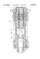
- FIG. 1is a longitudinal cross section of an electrical connector embodying the present invention, showing the components of the connector in unassembled, spaced apart relationship;
- FIG. 2is a longitudinal cross section of the electrical connector shown in FIG. 1, showing the components of the connector in assembled relationship.
- an electrical connector 10has a male member 12 and a female member 14, both of which respectively have a body portion 16,18 that, preferably, is formed of a hard, rigid, electrically nonconductive material having an electrical resistivity of at least 10 10 ohm cm, and high resistance to water absorption.
- Suitable materials for formation of body portions 16,18 of the male and female members 12,14include, but are not limited to, thermoset plastics and thermoplastics such as urethane, polyphenyl sulfone, polyaryl sulfone, polychlorotrifluoroethylene (PCTFE), phenylene ether/phenylene oxide, polyester, alkyd encapsulating putty, granular and glass reinforced alkyds, fiber filled diallyl phthalates, high density polyethylene, rigid cast or molded epoxies, polyurethane rubber, standard electrical glass, low loss electrical borosilicate glass, and electrical ceramics such as steatite and alumina.
- thermoset plastics and thermoplasticssuch as urethane, polyphenyl sulfone, polyaryl sulfone, polychlorotrifluoroethylene (PCTFE), phenylene ether/phenylene oxide, polyester, alkyd encapsulating putty, granular and glass reinforced al
- the body portions 16,18may be formed by injection molding, compression or transfer molding, or casting.
- the body portions 16,18are constructed of glass filled thermoplastic urethane, and formed by injection molding.
- the body portions 16,18 of the male and female members 12,14may be formed of a relatively soft, resiliently compressible material.
- Suitable materialsinclude both thermoset and thermoplastic elastomers, such as natural-rubber and synthetic rubber polymers.
- thermoset and thermoplastic elastomerssuch as natural-rubber and synthetic rubber polymers.
- a blend of polyethylene and neoprene rubberhas been found to be suitable for forming electrically nonconductive components of the connector embodying the present invention.
- the male member 12also includes a plurality of electrically conductive pins 20 that are preferably arranged in a predetermined pattern within a mold cavity prior to injection molding the body 16. Simultaneously with molding the body 16, a sheath 22 is formed about a portion of each of the pins 20 thereby encapsulating each of the pins not only within the body 16 but also within a respective sheath 22.
- the sheaths 22extend outwardly from a first face surface 24 of the body 16, which also has a second face surface 26 spaced from the first face surface 24.
- the body portion 16may be preformed without the pins 20, after which the pins 20 are inserted into prearranged holes and adhesively bonded to the body portion 16.
- Each of the pins 20have a first portion 28 completely encapsulated within the body 16 and a respective one of the sheaths 22, an exposed second portion 30 extending outwardly from a distal end of the sheath 22, and an exposed third portion 32 extending outwardly from the second face surface 26 of the body 16.
- the outer surface of the first, or encapsulated, portion 28 of the pins 20preferably have a plurality of inwardly extending annular grooves to aid in the retention of the pins 20 in the body 16 and to improve sealing of the body 16 and sheath 22 around each of the pins 20.
- the third portion 32 of the pins 20preferably have a socket formed therein for receiving the pin end of an insertable/removable solder lug that is soldered to a wire conductor (not shown).
- solder lugmay be directly formed on the outer end of the pin 20.
- first and second portions of two of the pins 20, and their respective sheaths 22,are shown in FIG. 1.
- the body portion 18 of the female member 14has a first face surface 34, a second face surface 36 spaced from the first face surface 34, and a plurality of integrally formed sheaths 38 extending outwardly from the first face surface 34.
- the female member 14also includes a plurality of electrically conductive sockets 40 that are arranged in the same predetermined pattern as the pins 20. Each of the sockets 40 are shaped to receive substantially all of the exposed second portion 30 of the pins 20 and grip the pins so that they are maintained in electrically conductive contact with the socket 40.
- the pin receiving portions of the sockets 40are shaped so that it has a depth slightly greater than the length of the exposed first portion 28 of the pins 20 to assure that the pins will not “bottom out” in the socket. Also, it is desirable that the end of the sheaths 22,38 surrounding the pins and sockets be slightly spaced apart to preclude potential wear or damage to the sheaths.
- Each of the sockets 40have a first portion 42 in which the outer perimeter of the socket is completely encapsulated within the body 18 and a respective one of the sheaths 38 of the female member 14, and a second portion 44 that extends outwardly from the second face surface 36 of the body 18.
- a plurality of annular groovesare provided along at least a portion of the length of the outer surface of the sockets 40 to assure retention of the socket in the body 18 and enhance sealing between the socket 40 and the body 18.
- the second portion 44 of the sockets 40preferably have a solder lug formed on an outer end for attachment of a wire conductor (not shown).
- the body portion 18 and the sheaths 38 of the female member 14are desirably simultaneously formed by injection molding, compression or transfer molding, casting, or preformed and adhesively joined with the sockets 40, in the manner described above with respect to the body portion 16 of the male member 12.
- the electrical connector 10 embodying the present inventionalso has a coupling member 46 that is preferably formed of an injection moldable, resiliently compressible and electrically nonconductive material such as thermoplastic rubber.
- a coupling member 46that is preferably formed of an injection moldable, resiliently compressible and electrically nonconductive material such as thermoplastic rubber.
- thermoplastic rubbere.g., polyethylene and neoprene rubber
- the coupling member 46has a hardness of from about 40 to about 70 durometer as measured by the Shore A scale.
- the coupling member 46may be formed of a rigid nonconductive material. This combination of soft body members and hard coupling materials provides somewhat less sealing between the internal passageways 52 in the coupling member 46 (described below) and the respective sheaths 22,38 of the male and female body members 12,14.
- the coupling member 46may be advantageously formed of two separate materials.
- the coupling member 46has a body portion formed of a relatively soft, resiliently compressible material, such as the above described blend of polyethylene and neoprene rubber, and a thin externally disposed casing formed of a flexible nonconductive material having a hardness greater than that of the body portion.
- the casingis disposed about the circumferential surface areas of the body portion and may extend over one, or both, of the ends of the coupling member.
- the casingis formed of a material such as high density polyethylene that, during molding, is self-bonding to the body portion.
- the casinghas a thickness of about 0.050 in (0.13 mm) in the areas surrounding the cylindrical peripheral surface of the body portion, and a thickness of about 0.100 in (0.25 mm) in the radial areas over, or adjacent, the end faces.
- the coupling member 46has a first face surface 48 that is shaped to abut the first face surface 24 of the male member 12, and a second face surface 50 that is shaped to enable it to abut the first face surface 34 of the female member 14.
- the coupling member 46also has a plurality of passageways 52 extending between the first and second face surfaces 48,50 of the coupling 46.
- the passageways 52are arranged in the same predetermined pattern as the pins 20 and the sockets 40. It is also desirable that the coupling member 46 have a locator hole 54 adapted to receive a locator pin 56, preferably provided on the female member 14, to aid radial orientation of the coupling 46 when connecting the components together.
- a keymay be provided on an external circumferential surface of the coupling member 46, and conveniently formed of the same relatively hard material as the casing. The key, being formed of the relatively hard material, is capable of being effortlessly inserted into a keyway, described below, for relative orientation and alignment with a mating member.
- Each of the passageways 52have an internal wall surface that is shaped to receive and completely surround each of the sheaths 22,38 on the body portions 16,18 of the male and female members 12,14.
- the internal wall surfacesmay advantageously have a smooth cylindrical surface with an internal diameter substantially the same as, or even slightly greater than, the external diameter of the sheaths 20,40.
- the body portions 16,18 and sheaths 22,38 of the male and female members 12,14are desirably formed of a rigid material and the coupling member 46 formed of a resiliently compressible elastomer.
- Each of the passageways 52 in the coupling member 46 of the preferred embodimenthave a generally circular cross sectional shape in which at least one, and desirably a plurality of, annular alternating grooves 58 and ridges 60 are formed.
- the ridges 60preferably have an internal diameter slightly less than the diameter of the sheaths 22,38 so that, when the sheaths are inserted into the passageways 52, each of the ridges 60 form a lip, or O-ring type, seal about the circumference of each sheath.
- the ridges 60push water away from the pin-socket connection. It has also been found that if, after initial connection of the components, the components are subsequently slightly separated, e.g., moved apart about 1/4 inch (0.64 cm), and then rejoined, the ridges coact to provide a pumping action that further clears water from the pin-socket joint.
- each of the sheaths 22,38have an external diameter of 0.200 inches (0.079 cm), and each of the ridges 60 have a diameter of 0.150 inches (0.059 cm).
- the annular grooves 58 between the ridges 60 in the passageways 52have a diameter of 0.205 inches (0.081 cm) which is slightly greater than the external diameter of the sheaths 22,38.
- the coupling member 46is formed of a rigid material, and the respective body portions 16,18 and sheaths 22,38 of the male and female members 12,14 formed of a resiliently compressible elastomeric material, the ridges 60 may be advantageously disposed on the exterior surface of the sheaths 22,38.
- the coupling member 46is formed of a resiliently compressible elastomeric material
- the sealing pressure imposed by the passageways 52 about each of the sheaths 22,38will increase in response to increased pressure on the outer circumferential surface 62, even if the sheaths 22,38 are formed of a somewhat softer material than the coupling 46.
- the electrical connector 10when used with a rigid coupling member 46, the electrical connector 10 will be limited to use in relatively shallow water depths, e.g., up to about 125 feet.
- the electrical connector 10 embodying the present inventionmay be constructed with either rigid or resiliently compressible male and female body members 16,18, and either a resiliently compressible or rigid coupling member 46. The only combination of rigid and compressible components that would not provide a waterproof connector is when all of the components are formed of rigid materials.
- the internal passageways 52would preferably be formed to a diameter of, for example, about 0.210 inches (0.083 cm).
- the connector 10can be adapted for use in applications having very different environmental requirements.
- the coupling member 46is reversible, i.e., it can be installed with either face 48,50 abutting either the male member 12 or the female member 14.
- the electrical connector 10may have pins 20 and sockets 40 disposed in the same body member.
- each half of the connectormay be arranged so that one half of the contacts are male members, and the remaining half female members.
- the coupling membermay be split longitudinally to form two components, one for each group of mating male-female members.
- the sheaths 22 surrounding the pins 20have a length of 0.581 inch (1.48 cm) and the sheaths 38 surrounding the sockets 40 have a length of 0.400 inch (1.02 cm).
- the total combined length of the sheaths 22,38is 0.981 inches (2.49 cm).
- the length of the coupling member 46, and accordingly the length of the passageways 52 in the coupling memberis 1.081 inches (2.75 cm). Therefore, upon assembly, as described below in additional detail, there will be a gap, or "stand-of distance", of about 0.100 inch (0.25 cm) between the ends of the sheaths 22,38.
- the length of the sheaths 22 surrounding the pins 20is longer than the length of the sheaths 38 formed around the sockets 40. Therefore, there is more contact surface between the pin sheaths 22 and the internal surfaces of the passageways 52 in the coupling 46 than between the socket sheaths 38 and the passageways. Because of the longer contact area, the coupling member 46 will, upon disassembly, be captured by and retained with the male member 12. Also, because each of the passageways 52 is longer than the combined length of the pin sheath and the exposed pin portion 30, each of the exposed pin portions 30 are completely surrounded and protects the pins 20 from damage during handling or repair operations.
- the electrical connector 10includes a means 64 for maintaining the first and second face surfaces 48,50 of the coupling 46 in respective abutting contact with the first face surfaces 24,34 of the male and female members 12,14,
- the means 64includes a female adaptor member 66 having internal threads 68 which are threadably engageable with a plurality of threads 70 provided on a circumferential surface of the female member 14.
- the female adaptor 66secures the female member 14 in a fixed mounted position against a wall or case surface by drawing an annular shoulder on the circumference of the female member against the wall in response to tightening the threaded connection between the adaptor 66 and female member 14.
- a male adaptor member 72has internal threads 74, formed adjacent one end, which are adapted to threadably engage a plurality of external threads 76 formed on the male member 12.
- the male adaptor 76preferably has a provision for receiving a cable containing a plurality of wires in the other end and for sealing the entrance of the cable into the male adaptor 72.
- the cablemay be directly molded to the male member 12, thereby forming a single integrated component.
- the body portion of either the male member or the female member 14is formed of a relatively soft elastomeric material, in certain configurations it may be desirable to provide a harder casing about the member. Suitable, mutually compatible, body and casing materials were described above with respect to an alternate embodiment of the coupling member 46.
- the external threads 70,76 on the respective female and male members 14,12may advantageously be formed of the same harder material as the casing.
- the means 64 for maintaining the coupling 46 and the male and female members 12,14 in their respective abutting relationshipsalso includes a rigid outer shell 78 that has a plurality of internal threads 80 disposed at one end of the shell that are adapted to mate with a plurality of external threads 82 provided on the female adaptor member 66.
- the shell 78also has an internally disposed is groove 84 adjacent the other end which is adapted to receive a snap ring 86 that, when the connector 10 is assembled as shown in FIG. 2, abuts a shoulder 88 formed on the outer surface of the male adapter member 72. It is also desirable that the outer shell 78 have a plurality of open slots 90 extending through the periphery of the shell.
- the slots 90advantageously provide an aid to gripping and turning the shell during assembly or disassembly of the connector, and additionally provide an important self cleaning action. For these purposes, it is even desirable that at least part of the threaded portion of the outer shell 78 also have open slots 90 through the shell.
- the means 64 for maintaining the first and second face surfaces 48,50 of the coupling member 46 in respective abutting contact with the respective first face surfaces 24,34 of male and female members 12,14may comprise one or more shell or retention members that mechanically interact directly with a predefined shoulder or other surface to positively fix the respective position of the element components.
- the female adaptor member 66, the male adaptor member 72, and the shell 78are all constructed of a rigid plastic material, such as fiberglass filled polyurethane, that is electrically nonconductive, resistant to corrosion, and easily formable by conventional molding techniques.
- the coupling member 46is constructed with an external key, a preselected one, or both, of the adaptor members may have a mating keyway formed in the internal bore of the respective adaptor.
- the electrical connector 10 embodying the preferred arrangement of the present inventionis assembled, as shown in FIG. 2, by first inserting the female member 14 through one side of an aperture 92 in a data box or control panel, with a shoulder of the female member having an o-ring seal disposed therein in contact with the panel.
- the female adapter member 66is then threaded onto the female member 14 and tightened against the mounting wall or panel. This effectively locks the female member 14 in place with respect to the fixed wall surface.
- the elastomeric coupling member 46is then inserted over the pins 20 and the sheaths 22 of the male member 12. Next, while not entirely necessary because of the below described subsequent drawing of the element together, the coupling member 46 is desirably pushed onto the male member 12 until the second face surface 48 of the coupling member is in abutting contact with the face surface 24 of the body member 16.
- the male adapter member 72is then joined with the assembled coupling and male member 46,12 by threading the external threads 76 on the male member 12 into the internal threads 74 in the male adapter member 72.
- the individual lead wires from a line cable assemblyare attached to the ends, i.e., the third portion 32, of the pins 20.
- the assembled coupling member 46, male member with wires attached, and male adaptor member 72are then inserted, as a unit, through the left end (as viewed in FIGS. 1 and 2) of the outer shell 78 to a position at which the shoulder 88 on the male adapter member 72 passes to the right of the groove 84 in the outer shell 78.
- the snap ring 86is then inserted into the groove 84 which coacts with the shoulder 84 to prevent leftward movement of the male adaptor member 72 and the components previously assembled therewith.
- the coupling member 46, male member 12 and the male adaptor 72are rotated, if needed, to align the locator hole 54 in the coupling member with the locator pin 56.
- the assemblymay be rotated to align the key with the keyway formed in the female adaptor member.
- the outer shell 78is then moved into contact with the female adaptor member 66 and rotated to engage the internal threads 80 on the outer shell with the external threads 82 on the female adapter member. Tightening the outer shell 78 against the female adapter member 66 will draw the male and female members 12,14, toward the coupling member 46 that is positioned between the male and female members.
- the second face surface 50 of the coupling member 46 and the first face surface 34 of the female member 14, and the first face surface 24 of the male member 12 and the first face surface 48 of the coupling member 46are in respective abutting contact with each other.
- the exposed pins 20 of the male member 12 captured by, and maintained in electrical contact with, the sockets 40, and the sheaths 22,38 of both the male and female members 12,14are effectively sealed by the passageways 52 of the resiliently compressible coupling member 46.
- the length of the sheaths 22 of the male member 12are longer than sheaths 38 of the female member 14.
- the inwardly extending shoulder 94 formed on the outer shell 78will pull the coupling member 46 away from of the female member 14.
- the coupling member 46is captured by, and retained on, the male member 12. This makes subsequent reassembly, particularly underwater, easier because it eliminates the need to separately orient and install the coupling member 46 on the male member 12.
- the coupling member 46extends beyond the ends of the pins 20 of the male member 12, thereby protecting the pins when the connector 10 is in an uncoupled state.
- the assembled electrical connector 10is easily disassembled, in the field, by reversal of the above described assembly procedure.
- the connector 10can be disassembled and reassembled for service, even underwater if necessary.
- the coupling member 46is immediately field replaceable. Also, if they are not part of an assembly molded as a unit with their respective cables, the male and female member 12,14 may be individually replaced by removing the solder tabs from the socket connection provided on the ends of the pins 20 and the sockets 40.
- the electrical connector 10is used as a line connector, i.e., without one of the members being mounted in a box or to a wall.
- a line connectori.e., without one of the members being mounted in a box or to a wall.
- Other applications, changes and modifications of the above described electrical connectormay similarly be made without departing from the spirit and scope of the present invention.
- the electrical connector 10 embodying the present inventionadvantageously provides protective sheaths 22,38 around both the pins 20 of the male member 12 and the sockets 40 of the female member 38.
- the sheaths 22,38 around both electrical contact elementsprovide increased bonding surface area to assure a tight waterproof seal with the surrounding body.
- the sheaths 22,38also provide increased structural support for both contact elements, and increases the electrical signal crossover distance between adjacently disposed conductors thereby improving the electrical isolation of the components.
- the present inventionis particularly useful in applications that require sealing of electrical connections against adverse environmental conditions such as underwater data acquisition and transmission systems, subsurface or ground level instruments subjected to adverse operational and atmospheric environments such as seismic exploration applications, and other uses where it is desirable to protect the electrical contact portions of the connector.
- All of the electrical contact elementsi.e., both the pins and their mating sockets, are surrounded by a protective sheath that provides increased bonding surface between the respective contact element and its supporting nonconductive material.
- the protective sheathalso improves the electrical separation of the conductive elements.
- the present inventionbecause of the coupling provided between components housing the electrical contact elements, also has important uses in applications where the electrical connector is subjected to high vibration or shock, such as in rough terrain vehicles and earthmoving machines.
- the electrical connector 10 embodying the present inventioncomprises individual components that can be disassembled, the coupling member replaced, and the connector reassembled, even underwater, without the need of special tools or repair facilities.
- the electrical connector described above and defined by the claimsis particularly suited for use in remote geographical locations where repair facilities are not readily available.
Landscapes
- Connector Housings Or Holding Contact Members (AREA)
Abstract
Description
Claims (11)
Priority Applications (1)
| Application Number | Priority Date | Filing Date | Title |
|---|---|---|---|
| US08/486,357US5704799A (en) | 1994-04-11 | 1995-06-07 | Field repairable electrical connector |
Applications Claiming Priority (2)
| Application Number | Priority Date | Filing Date | Title |
|---|---|---|---|
| US08/226,009US5470248A (en) | 1994-04-11 | 1994-04-11 | Field repairable electrical connector |
| US08/486,357US5704799A (en) | 1994-04-11 | 1995-06-07 | Field repairable electrical connector |
Related Parent Applications (1)
| Application Number | Title | Priority Date | Filing Date |
|---|---|---|---|
| US08/226,009Continuation-In-PartUS5470248A (en) | 1994-04-11 | 1994-04-11 | Field repairable electrical connector |
Publications (1)
| Publication Number | Publication Date |
|---|---|
| US5704799Atrue US5704799A (en) | 1998-01-06 |
Family
ID=46202697
Family Applications (1)
| Application Number | Title | Priority Date | Filing Date |
|---|---|---|---|
| US08/486,357Expired - LifetimeUS5704799A (en) | 1994-04-11 | 1995-06-07 | Field repairable electrical connector |
Country Status (1)
| Country | Link |
|---|---|
| US (1) | US5704799A (en) |
Cited By (27)
| Publication number | Priority date | Publication date | Assignee | Title |
|---|---|---|---|---|
| US6142805A (en)* | 1999-09-03 | 2000-11-07 | Geo Space Corporation | Waterproof geophysical connector |
| US6361342B1 (en)* | 2000-09-11 | 2002-03-26 | Baker Hughes Incorporated | Pothead with pressure energized lip seals |
| US6402539B1 (en)* | 2001-10-16 | 2002-06-11 | Ocean Design, Inc. | Self-contained underwater cable branching apparatus and method |
| US6443780B2 (en)* | 1999-08-23 | 2002-09-03 | Baker Hughes Incorporated | Conductor assembly for pothead connector |
| US20030220005A1 (en)* | 2002-05-25 | 2003-11-27 | John Kedzierski | Electrical connector |
| US6676447B1 (en) | 2002-07-18 | 2004-01-13 | Baker Hughes Incorporated | Pothead connector with elastomeric sealing washer |
| US6716063B1 (en) | 2000-02-28 | 2004-04-06 | Pgs Exploration (Us), Inc. | Electrical cable insert |
| US20040166732A1 (en)* | 2001-06-12 | 2004-08-26 | Oliver Schliese | Method for production of a gas-tight ducting for a contact through a wall and device for ducting an electrical contact through a wall |
| US7071588B1 (en)* | 2004-05-20 | 2006-07-04 | Yeomans Chicago Corporation | Pump motor penetration assembly |
| US20070044772A1 (en)* | 2005-08-26 | 2007-03-01 | Denso Corporation | Fuel feed apparatus having electric connector |
| US20070077798A1 (en)* | 2005-09-30 | 2007-04-05 | Yazaki Corporation | Connector |
| US20070155231A1 (en)* | 2006-01-04 | 2007-07-05 | Tang Neil H | Coaxial cable connector |
| US20070243771A1 (en)* | 2006-04-14 | 2007-10-18 | Arthur Dyck | Coaxial connector with maximized surface contact and method |
| US20070267210A1 (en)* | 2006-05-19 | 2007-11-22 | Kesler James R | Article and method for providing a seal for an encapsulated device |
| US20080230359A1 (en)* | 2007-03-22 | 2008-09-25 | Leccia Brad R | Electrically insulated conductor connection assemblies and associated method |
| US20090107980A1 (en)* | 2007-10-29 | 2009-04-30 | Smiths Medical Asd, Inc. | Hot plate heater for a respiratory system |
| EP2234216A1 (en)* | 2009-03-25 | 2010-09-29 | Culture Bright Limited | Connector for underwater devices |
| US7837509B1 (en)* | 2005-02-10 | 2010-11-23 | Switzer Calvin T | Recessed light extension socket |
| US8137136B1 (en)* | 2011-05-31 | 2012-03-20 | Precision Engine Controls Corporation | Electrical disconnect for hazardous areas |
| US20140038443A1 (en)* | 2012-08-01 | 2014-02-06 | Itt Manufacturing Enterprises Llc | Electrical connector system with replaceable sealing element |
| US20150144398A1 (en)* | 2013-11-26 | 2015-05-28 | Andrew Llc | Adapter for sealing cover for electrical interconnections |
| US20150378125A1 (en)* | 2013-02-15 | 2015-12-31 | Prysmian S.P.A. | Wet mateable connection assembly for electrical and/or optical cables |
| GB2537346A (en)* | 2015-02-26 | 2016-10-19 | C R Encapsulation Ltd | Electrical connector apparatus, system and method |
| EP3235087A4 (en)* | 2014-12-16 | 2018-08-08 | CommScope Technologies LLC | Adapter for sealing cover for electrical interconnections |
| US20190386418A1 (en)* | 2018-06-15 | 2019-12-19 | Yazaki Corporation | Liquid-proof connector |
| US20200021053A1 (en)* | 2018-02-08 | 2020-01-16 | Anhui Zhongding Sealing Parts Co.,Ltd | Power connector |
| US10693254B2 (en)* | 2018-05-21 | 2020-06-23 | Japan Aviation Electronics Industry, Limited | Dummy pin |
Citations (48)
| Publication number | Priority date | Publication date | Assignee | Title |
|---|---|---|---|---|
| DE63398C (en)* | H. KNAPPE in Schweidnitz i. Schles | Device for clamping any number of saw blades in horizontal gates | ||
| US2843133A (en)* | 1957-09-26 | 1958-07-15 | Jack L Barbara | Filter unit for pipes |
| US2881406A (en)* | 1955-06-20 | 1959-04-07 | Cannon Electric Co | Moisture seal for connectors |
| US3197730A (en)* | 1963-12-04 | 1965-07-27 | Richard L Hargett | Pressure-tight connector |
| US3449182A (en)* | 1966-05-16 | 1969-06-10 | Structural Fibers | Method of making a hollow,fiber-reinforced plastic pressure vessel |
| US3461529A (en)* | 1966-10-14 | 1969-08-19 | Textron Inc | Method of making a bearing |
| US3497864A (en)* | 1968-06-27 | 1970-02-24 | Us Navy | Underwater electrical cable connector |
| US3641479A (en)* | 1969-06-16 | 1972-02-08 | Obrien D G Inc | Underwater disconnectible connector |
| US3693133A (en)* | 1969-10-08 | 1972-09-19 | Inst Francais Du Petrole | Fluid tight electric connector |
| US3739330A (en)* | 1970-07-08 | 1973-06-12 | Mark Products | Geophone assembly |
| US3745511A (en)* | 1971-06-16 | 1973-07-10 | Mark Products | Multiconductor cable connector |
| US3783434A (en)* | 1972-08-10 | 1974-01-01 | Mark Iii Inc | Shielded cable coupler |
| US3888559A (en)* | 1972-04-13 | 1975-06-10 | Amp Inc | High voltage quick disconnect assembly |
| US3937545A (en)* | 1974-12-23 | 1976-02-10 | Ford Motor Company | Waterproof electrical connector |
| US3954154A (en)* | 1970-09-25 | 1976-05-04 | Kruppenbach John A | Towed land cable |
| US4032214A (en)* | 1976-04-21 | 1977-06-28 | Schlumberger Technology Corporation | Cable-termination assemblies and methods for manufacturing such assemblies |
| US4090759A (en)* | 1975-04-17 | 1978-05-23 | Amp Incorporated | Micro-miniature circular high voltage connector |
| US4150866A (en)* | 1977-08-26 | 1979-04-24 | Amp Incorporated | Environmentally sealed connector |
| US4284312A (en)* | 1978-12-21 | 1981-08-18 | Chrysler Corporation | Sealing type electrical connector |
| US4355855A (en)* | 1979-02-07 | 1982-10-26 | Dimitri Rebikoff | Deep water connector |
| US4445741A (en)* | 1981-10-13 | 1984-05-01 | Houston Geophysical Products, Inc. | Double-plug seismic connector |
| GB2131633A (en)* | 1982-12-13 | 1984-06-20 | Reed Products Inc | Underwater electrical cable connectors |
| US4480151A (en)* | 1982-07-19 | 1984-10-30 | Hilliard Dozier | Temperature stable hermetically sealed terminal |
| US4497531A (en)* | 1981-07-23 | 1985-02-05 | Amp Incorporated | Electrical connector |
| US4588247A (en)* | 1982-05-19 | 1986-05-13 | Souriau & C. | Electric connectors intended particularly to be used in a liquid medium particularly under pressure |
| US4589939A (en)* | 1984-02-17 | 1986-05-20 | Raychem Corporation | Insulating multiple-conductor cables using coated insert means |
| USH113H (en)* | 1986-01-27 | 1986-08-05 | Waterblock and strain relief for electrical connectors | |
| US4609247A (en)* | 1983-07-11 | 1986-09-02 | Houston Geophysical Products, Inc. | Connector having two seal-rings of different diameters |
| US4632482A (en)* | 1982-04-15 | 1986-12-30 | Allied Corporation | Contact for an electrical connector |
| US4758174A (en)* | 1987-01-20 | 1988-07-19 | Molex Incorporated | Environmentally sealed electrical connector |
| US4767356A (en)* | 1985-11-08 | 1988-08-30 | Souriau & Cie | Electrical connectors, particularly connectors fluid-tight on immersion in a liquid |
| US4767349A (en)* | 1983-12-27 | 1988-08-30 | Schlumberger Technology Corporation | Wet electrical connector |
| US4790768A (en)* | 1986-05-20 | 1988-12-13 | Total Compagnie Francaise Des Petroles | Immersible electrical coupling |
| US4820170A (en)* | 1984-12-20 | 1989-04-11 | Amp Incorporated | Layered elastomeric connector and process for its manufacture |
| US4861288A (en)* | 1987-12-14 | 1989-08-29 | Royal Technologies Usa, Inc. | Electrical cordset |
| US4921452A (en)* | 1988-08-22 | 1990-05-01 | Hilliard Dozier | Breakaway hermetically sealed electrical terminal |
| US5014813A (en)* | 1988-12-27 | 1991-05-14 | Fussell Don L | Water-proof geophone housing |
| US5120237A (en)* | 1991-07-22 | 1992-06-09 | Fussell Don L | Snap on cable connector |
| US5120268A (en)* | 1990-08-07 | 1992-06-09 | Al Gerrans | Marine electrical connector |
| US5130954A (en)* | 1991-07-22 | 1992-07-14 | Fussell Don L | Leader cable anchor for a geophone |
| US5145410A (en)* | 1990-08-06 | 1992-09-08 | Yazaki Corporation | Waterproof connector |
| US5183966A (en)* | 1990-11-19 | 1993-02-02 | Western Atlas International, Inc. | Termination assembly with improved waterblock |
| US5199893A (en)* | 1991-07-22 | 1993-04-06 | Fussell Don L | Seismic connector with replaceable seal |
| US5297974A (en)* | 1992-09-14 | 1994-03-29 | Fussell Don L | Positively released seismic cable connector |
| US5362258A (en)* | 1992-09-09 | 1994-11-08 | Wilo Gmbh | Cable-attaching device for a pump |
| US5387119A (en)* | 1993-10-08 | 1995-02-07 | Tescorp Seismic Products, Inc. | Waterproof electrical connector |
| US5470248A (en)* | 1994-04-11 | 1995-11-28 | Tescorp Seismic Products, Inc. | Field repairable electrical connector |
| US5542856A (en)* | 1994-04-11 | 1996-08-06 | Tescorp Seismic Products, Inc. | Field repairable electrical connector |
- 1995
- 1995-06-07USUS08/486,357patent/US5704799A/ennot_activeExpired - Lifetime
Patent Citations (49)
| Publication number | Priority date | Publication date | Assignee | Title |
|---|---|---|---|---|
| DE63398C (en)* | H. KNAPPE in Schweidnitz i. Schles | Device for clamping any number of saw blades in horizontal gates | ||
| US2881406A (en)* | 1955-06-20 | 1959-04-07 | Cannon Electric Co | Moisture seal for connectors |
| US2843133A (en)* | 1957-09-26 | 1958-07-15 | Jack L Barbara | Filter unit for pipes |
| US3197730A (en)* | 1963-12-04 | 1965-07-27 | Richard L Hargett | Pressure-tight connector |
| US3449182A (en)* | 1966-05-16 | 1969-06-10 | Structural Fibers | Method of making a hollow,fiber-reinforced plastic pressure vessel |
| US3461529A (en)* | 1966-10-14 | 1969-08-19 | Textron Inc | Method of making a bearing |
| US3497864A (en)* | 1968-06-27 | 1970-02-24 | Us Navy | Underwater electrical cable connector |
| US3641479A (en)* | 1969-06-16 | 1972-02-08 | Obrien D G Inc | Underwater disconnectible connector |
| US3693133A (en)* | 1969-10-08 | 1972-09-19 | Inst Francais Du Petrole | Fluid tight electric connector |
| US3739330A (en)* | 1970-07-08 | 1973-06-12 | Mark Products | Geophone assembly |
| US3954154A (en)* | 1970-09-25 | 1976-05-04 | Kruppenbach John A | Towed land cable |
| US3745511A (en)* | 1971-06-16 | 1973-07-10 | Mark Products | Multiconductor cable connector |
| US3888559A (en)* | 1972-04-13 | 1975-06-10 | Amp Inc | High voltage quick disconnect assembly |
| US3783434A (en)* | 1972-08-10 | 1974-01-01 | Mark Iii Inc | Shielded cable coupler |
| US3937545A (en)* | 1974-12-23 | 1976-02-10 | Ford Motor Company | Waterproof electrical connector |
| US4090759A (en)* | 1975-04-17 | 1978-05-23 | Amp Incorporated | Micro-miniature circular high voltage connector |
| US4032214A (en)* | 1976-04-21 | 1977-06-28 | Schlumberger Technology Corporation | Cable-termination assemblies and methods for manufacturing such assemblies |
| US4150866A (en)* | 1977-08-26 | 1979-04-24 | Amp Incorporated | Environmentally sealed connector |
| US4284312A (en)* | 1978-12-21 | 1981-08-18 | Chrysler Corporation | Sealing type electrical connector |
| US4355855A (en)* | 1979-02-07 | 1982-10-26 | Dimitri Rebikoff | Deep water connector |
| US4497531A (en)* | 1981-07-23 | 1985-02-05 | Amp Incorporated | Electrical connector |
| US4445741A (en)* | 1981-10-13 | 1984-05-01 | Houston Geophysical Products, Inc. | Double-plug seismic connector |
| US4445741B1 (en)* | 1981-10-13 | 1991-06-04 | Houston Geophysical Products I | |
| US4632482A (en)* | 1982-04-15 | 1986-12-30 | Allied Corporation | Contact for an electrical connector |
| US4588247A (en)* | 1982-05-19 | 1986-05-13 | Souriau & C. | Electric connectors intended particularly to be used in a liquid medium particularly under pressure |
| US4480151A (en)* | 1982-07-19 | 1984-10-30 | Hilliard Dozier | Temperature stable hermetically sealed terminal |
| GB2131633A (en)* | 1982-12-13 | 1984-06-20 | Reed Products Inc | Underwater electrical cable connectors |
| US4609247A (en)* | 1983-07-11 | 1986-09-02 | Houston Geophysical Products, Inc. | Connector having two seal-rings of different diameters |
| US4767349A (en)* | 1983-12-27 | 1988-08-30 | Schlumberger Technology Corporation | Wet electrical connector |
| US4589939A (en)* | 1984-02-17 | 1986-05-20 | Raychem Corporation | Insulating multiple-conductor cables using coated insert means |
| US4820170A (en)* | 1984-12-20 | 1989-04-11 | Amp Incorporated | Layered elastomeric connector and process for its manufacture |
| US4767356A (en)* | 1985-11-08 | 1988-08-30 | Souriau & Cie | Electrical connectors, particularly connectors fluid-tight on immersion in a liquid |
| USH113H (en)* | 1986-01-27 | 1986-08-05 | Waterblock and strain relief for electrical connectors | |
| US4790768A (en)* | 1986-05-20 | 1988-12-13 | Total Compagnie Francaise Des Petroles | Immersible electrical coupling |
| US4758174A (en)* | 1987-01-20 | 1988-07-19 | Molex Incorporated | Environmentally sealed electrical connector |
| US4861288A (en)* | 1987-12-14 | 1989-08-29 | Royal Technologies Usa, Inc. | Electrical cordset |
| US4921452A (en)* | 1988-08-22 | 1990-05-01 | Hilliard Dozier | Breakaway hermetically sealed electrical terminal |
| US5014813A (en)* | 1988-12-27 | 1991-05-14 | Fussell Don L | Water-proof geophone housing |
| US5145410A (en)* | 1990-08-06 | 1992-09-08 | Yazaki Corporation | Waterproof connector |
| US5120268A (en)* | 1990-08-07 | 1992-06-09 | Al Gerrans | Marine electrical connector |
| US5183966A (en)* | 1990-11-19 | 1993-02-02 | Western Atlas International, Inc. | Termination assembly with improved waterblock |
| US5130954A (en)* | 1991-07-22 | 1992-07-14 | Fussell Don L | Leader cable anchor for a geophone |
| US5120237A (en)* | 1991-07-22 | 1992-06-09 | Fussell Don L | Snap on cable connector |
| US5199893A (en)* | 1991-07-22 | 1993-04-06 | Fussell Don L | Seismic connector with replaceable seal |
| US5362258A (en)* | 1992-09-09 | 1994-11-08 | Wilo Gmbh | Cable-attaching device for a pump |
| US5297974A (en)* | 1992-09-14 | 1994-03-29 | Fussell Don L | Positively released seismic cable connector |
| US5387119A (en)* | 1993-10-08 | 1995-02-07 | Tescorp Seismic Products, Inc. | Waterproof electrical connector |
| US5470248A (en)* | 1994-04-11 | 1995-11-28 | Tescorp Seismic Products, Inc. | Field repairable electrical connector |
| US5542856A (en)* | 1994-04-11 | 1996-08-06 | Tescorp Seismic Products, Inc. | Field repairable electrical connector |
Cited By (41)
| Publication number | Priority date | Publication date | Assignee | Title |
|---|---|---|---|---|
| US6443780B2 (en)* | 1999-08-23 | 2002-09-03 | Baker Hughes Incorporated | Conductor assembly for pothead connector |
| US6142805A (en)* | 1999-09-03 | 2000-11-07 | Geo Space Corporation | Waterproof geophysical connector |
| US6716063B1 (en) | 2000-02-28 | 2004-04-06 | Pgs Exploration (Us), Inc. | Electrical cable insert |
| US6361342B1 (en)* | 2000-09-11 | 2002-03-26 | Baker Hughes Incorporated | Pothead with pressure energized lip seals |
| US20040166732A1 (en)* | 2001-06-12 | 2004-08-26 | Oliver Schliese | Method for production of a gas-tight ducting for a contact through a wall and device for ducting an electrical contact through a wall |
| US6994589B2 (en)* | 2001-06-12 | 2006-02-07 | Siemens Aktiengesellschaft | Method for production of a gas-tight ducting for a contact through a wall and device for ducting an electrical contact through a wall |
| US6402539B1 (en)* | 2001-10-16 | 2002-06-11 | Ocean Design, Inc. | Self-contained underwater cable branching apparatus and method |
| US20030220005A1 (en)* | 2002-05-25 | 2003-11-27 | John Kedzierski | Electrical connector |
| US6722902B2 (en)* | 2002-05-25 | 2004-04-20 | John Kedzierski | Solder-less, crimp-less electrical connector |
| US6676447B1 (en) | 2002-07-18 | 2004-01-13 | Baker Hughes Incorporated | Pothead connector with elastomeric sealing washer |
| US7071588B1 (en)* | 2004-05-20 | 2006-07-04 | Yeomans Chicago Corporation | Pump motor penetration assembly |
| US7837509B1 (en)* | 2005-02-10 | 2010-11-23 | Switzer Calvin T | Recessed light extension socket |
| US20070044772A1 (en)* | 2005-08-26 | 2007-03-01 | Denso Corporation | Fuel feed apparatus having electric connector |
| US7367325B2 (en)* | 2005-08-26 | 2008-05-06 | Denso Corporation | Fuel feed apparatus having electric connector |
| US20070077798A1 (en)* | 2005-09-30 | 2007-04-05 | Yazaki Corporation | Connector |
| US7381072B2 (en)* | 2005-09-30 | 2008-06-03 | Yazaki Corporation | Connector having a strain relief structure |
| US20070155231A1 (en)* | 2006-01-04 | 2007-07-05 | Tang Neil H | Coaxial cable connector |
| WO2007081438A3 (en)* | 2006-01-04 | 2007-09-13 | Antronix Inc | Coaxial cable connector |
| US20070243771A1 (en)* | 2006-04-14 | 2007-10-18 | Arthur Dyck | Coaxial connector with maximized surface contact and method |
| US7377809B2 (en) | 2006-04-14 | 2008-05-27 | Extreme Broadband Engineering, Llc | Coaxial connector with maximized surface contact and method |
| US20070267210A1 (en)* | 2006-05-19 | 2007-11-22 | Kesler James R | Article and method for providing a seal for an encapsulated device |
| US7683261B2 (en)* | 2006-05-19 | 2010-03-23 | Schweitzer Engineering Laboratories, Inc. | Article and method for providing a seal for an encapsulated device |
| US20080230359A1 (en)* | 2007-03-22 | 2008-09-25 | Leccia Brad R | Electrically insulated conductor connection assemblies and associated method |
| US7695300B2 (en)* | 2007-03-22 | 2010-04-13 | Eaton Corporation | Electrically insulated conductor connection assemblies and associated method |
| US20090107980A1 (en)* | 2007-10-29 | 2009-04-30 | Smiths Medical Asd, Inc. | Hot plate heater for a respiratory system |
| US8049143B2 (en)* | 2007-10-29 | 2011-11-01 | Smiths Medical Asd, Inc. | Hot plate heater for a respiratory system |
| EP2234216A1 (en)* | 2009-03-25 | 2010-09-29 | Culture Bright Limited | Connector for underwater devices |
| US8137136B1 (en)* | 2011-05-31 | 2012-03-20 | Precision Engine Controls Corporation | Electrical disconnect for hazardous areas |
| US20140038443A1 (en)* | 2012-08-01 | 2014-02-06 | Itt Manufacturing Enterprises Llc | Electrical connector system with replaceable sealing element |
| US8708726B2 (en)* | 2012-08-01 | 2014-04-29 | Itt Manufacturing Enterprises Llc | Electrical connector system with replaceable sealing element |
| US20150378125A1 (en)* | 2013-02-15 | 2015-12-31 | Prysmian S.P.A. | Wet mateable connection assembly for electrical and/or optical cables |
| US9477060B2 (en)* | 2013-02-15 | 2016-10-25 | Prysmian S.P.A. | Wet mateable connection assembly for electrical and/or optical cables |
| US20150144398A1 (en)* | 2013-11-26 | 2015-05-28 | Andrew Llc | Adapter for sealing cover for electrical interconnections |
| US10404048B2 (en)* | 2013-11-26 | 2019-09-03 | Commscope Technologies Llc | Adapter for sealing cover for electrical interconnections |
| EP3235087A4 (en)* | 2014-12-16 | 2018-08-08 | CommScope Technologies LLC | Adapter for sealing cover for electrical interconnections |
| GB2537346A (en)* | 2015-02-26 | 2016-10-19 | C R Encapsulation Ltd | Electrical connector apparatus, system and method |
| US20200021053A1 (en)* | 2018-02-08 | 2020-01-16 | Anhui Zhongding Sealing Parts Co.,Ltd | Power connector |
| US10819061B2 (en)* | 2018-02-08 | 2020-10-27 | Anhui Zhongding Sealing Parts Co., Ltd | Power connector |
| US10693254B2 (en)* | 2018-05-21 | 2020-06-23 | Japan Aviation Electronics Industry, Limited | Dummy pin |
| US20190386418A1 (en)* | 2018-06-15 | 2019-12-19 | Yazaki Corporation | Liquid-proof connector |
| US10998663B2 (en)* | 2018-06-15 | 2021-05-04 | Yazaki Corporation | Liquid-proof connector |
Similar Documents
| Publication | Publication Date | Title |
|---|---|---|
| US5704799A (en) | Field repairable electrical connector | |
| US5470248A (en) | Field repairable electrical connector | |
| US5542856A (en) | Field repairable electrical connector | |
| EP0730322B1 (en) | Underwater electrical connector | |
| EP0649188B1 (en) | Waterproof electrical connector | |
| US5984724A (en) | Waterproof low temperature geophysical connector | |
| US6482036B1 (en) | Waterproof electrical connector | |
| US3879097A (en) | Electrical connectors for telemetering drill strings | |
| US6716063B1 (en) | Electrical cable insert | |
| US4402566A (en) | Field repairable electrical connector | |
| US4557538A (en) | Assembly for effecting an electric connection through a pipe formed of several elements | |
| US5797761A (en) | Power connector assembly | |
| US3994552A (en) | Submersible pipe electrical cable assembly | |
| US5711685A (en) | Electrical connector having removable seal at cable entry end | |
| US4679875A (en) | Attachment of electric cable to submergible pump motor heads | |
| US6142805A (en) | Waterproof geophysical connector | |
| US8636549B2 (en) | Dynamic contact bayonet electrical connector having a small cylindrical tip and a larger conical middle part | |
| US5980317A (en) | Repairable electrical geophysical connector | |
| JPS5835485A (en) | Streamer device for underwater listening | |
| US5125848A (en) | Environmentally sealed hermaphroditic electric connector | |
| US3166371A (en) | Waterproof electrical connector | |
| US5878001A (en) | Repairable waterproof geophone housing | |
| EP0777303B1 (en) | Electrical connector assembly having replaceable sleeve seal | |
| US4249788A (en) | Waterproof multiple wire cable connecting device | |
| US3954319A (en) | Environment proof electrical connector assembly |
Legal Events
| Date | Code | Title | Description |
|---|---|---|---|
| AS | Assignment | Owner name:TESCORP SEISMIC PRODUCTS, INC., TEXAS Free format text:ASSIGNMENT OF ASSIGNORS INTEREST;ASSIGNOR:WOOD, RICHARD G.;REEL/FRAME:007589/0749 Effective date:19950606 | |
| STCF | Information on status: patent grant | Free format text:PATENTED CASE | |
| AS | Assignment | Owner name:INPUT/OUTPUT, INC., A CORP. OF DELAWARE, TEXAS Free format text:ASSIGNMENT OF ASSIGNORS INTEREST;ASSIGNOR:TESCORP SEISMIC PRODUCTS, INC., A CORP. OF DELAWARE;REEL/FRAME:009893/0872 Effective date:19990330 | |
| FEPP | Fee payment procedure | Free format text:PAT HLDR NO LONGER CLAIMS SMALL ENT STAT AS SMALL BUSINESS (ORIGINAL EVENT CODE: LSM2); ENTITY STATUS OF PATENT OWNER: LARGE ENTITY | |
| FPAY | Fee payment | Year of fee payment:4 | |
| FPAY | Fee payment | Year of fee payment:8 | |
| FPAY | Fee payment | Year of fee payment:12 | |
| AS | Assignment | Owner name:ION GEOPHYSICAL CORPORATION,TEXAS Free format text:CHANGE OF NAME;ASSIGNOR:INPUT/OUTPUT, INC.;REEL/FRAME:024424/0191 Effective date:20070924 Owner name:INOVA GEOPHYSICAL CORPORATION,TEXAS Free format text:ASSIGNMENT OF ASSIGNORS INTEREST;ASSIGNOR:ION GEOPHYSICAL CORPORATION;REEL/FRAME:024424/0138 Effective date:20100519 Owner name:INOVA GEOPHYSICAL CORPORATION, TEXAS Free format text:ASSIGNMENT OF ASSIGNORS INTEREST;ASSIGNOR:ION GEOPHYSICAL CORPORATION;REEL/FRAME:024424/0138 Effective date:20100519 | |
| AS | Assignment | Owner name:INOVA LTD., CAYMAN ISLANDS Free format text:ASSIGNMENT OF ASSIGNORS INTEREST;ASSIGNOR:ION GEOPHYSICAL CORPORATION;REEL/FRAME:024651/0695 Effective date:20100707 |