US5704752A - Zero insertion force rivet device - Google Patents
Zero insertion force rivet deviceDownload PDFInfo
- Publication number
- US5704752A US5704752AUS08/325,171US32517195AUS5704752AUS 5704752 AUS5704752 AUS 5704752AUS 32517195 AUS32517195 AUS 32517195AUS 5704752 AUS5704752 AUS 5704752A
- Authority
- US
- United States
- Prior art keywords
- rivet
- axis
- rivet device
- strip
- collar
- Prior art date
- Legal status (The legal status is an assumption and is not a legal conclusion. Google has not performed a legal analysis and makes no representation as to the accuracy of the status listed.)
- Expired - Fee Related
Links
- 238000003780insertionMethods0.000titledescription9
- 230000037431insertionEffects0.000titledescription9
- 239000002184metalSubstances0.000claimsdescription8
- 229910052751metalInorganic materials0.000claimsdescription8
- 238000005476solderingMethods0.000claimsdescription3
- 239000000463materialSubstances0.000claimsdescription2
- 210000002105tongueAnatomy0.000description3
- 238000004519manufacturing processMethods0.000description2
- 229910000881Cu alloyInorganic materials0.000description1
- 229910001128Sn alloyInorganic materials0.000description1
- 229910000831SteelInorganic materials0.000description1
- 239000004020conductorSubstances0.000description1
- 239000006185dispersionSubstances0.000description1
- 230000000694effectsEffects0.000description1
- 230000005611electricityEffects0.000description1
- 230000002452interceptive effectEffects0.000description1
- LQBJWKCYZGMFEV-UHFFFAOYSA-Nlead tinChemical compound[Sn].[Pb]LQBJWKCYZGMFEV-UHFFFAOYSA-N0.000description1
- 238000000034methodMethods0.000description1
- 230000003014reinforcing effectEffects0.000description1
- 239000010959steelSubstances0.000description1
Images


Classifications
- H—ELECTRICITY
- H01—ELECTRIC ELEMENTS
- H01R—ELECTRICALLY-CONDUCTIVE CONNECTIONS; STRUCTURAL ASSOCIATIONS OF A PLURALITY OF MUTUALLY-INSULATED ELECTRICAL CONNECTING ELEMENTS; COUPLING DEVICES; CURRENT COLLECTORS
- H01R4/00—Electrically-conductive connections between two or more conductive members in direct contact, i.e. touching one another; Means for effecting or maintaining such contact; Electrically-conductive connections having two or more spaced connecting locations for conductors and using contact members penetrating insulation
- H01R4/06—Riveted connections
- F—MECHANICAL ENGINEERING; LIGHTING; HEATING; WEAPONS; BLASTING
- F16—ENGINEERING ELEMENTS AND UNITS; GENERAL MEASURES FOR PRODUCING AND MAINTAINING EFFECTIVE FUNCTIONING OF MACHINES OR INSTALLATIONS; THERMAL INSULATION IN GENERAL
- F16B—DEVICES FOR FASTENING OR SECURING CONSTRUCTIONAL ELEMENTS OR MACHINE PARTS TOGETHER, e.g. NAILS, BOLTS, CIRCLIPS, CLAMPS, CLIPS OR WEDGES; JOINTS OR JOINTING
- F16B19/00—Bolts without screw-thread; Pins, including deformable elements; Rivets
- F16B19/04—Rivets; Spigots or the like fastened by riveting
- F16B19/08—Hollow rivets; Multi-part rivets
- F16B19/10—Hollow rivets; Multi-part rivets fastened by expanding mechanically
- F16B19/1027—Multi-part rivets
- F16B19/1036—Blind rivets
- F16B19/1081—Blind rivets fastened by a drive-pin
- F—MECHANICAL ENGINEERING; LIGHTING; HEATING; WEAPONS; BLASTING
- F16—ENGINEERING ELEMENTS AND UNITS; GENERAL MEASURES FOR PRODUCING AND MAINTAINING EFFECTIVE FUNCTIONING OF MACHINES OR INSTALLATIONS; THERMAL INSULATION IN GENERAL
- F16B—DEVICES FOR FASTENING OR SECURING CONSTRUCTIONAL ELEMENTS OR MACHINE PARTS TOGETHER, e.g. NAILS, BOLTS, CIRCLIPS, CLAMPS, CLIPS OR WEDGES; JOINTS OR JOINTING
- F16B2200/00—Constructional details of connections not covered for in other groups of this subclass
- F16B2200/40—Clamping arrangements where clamping parts are received in recesses of elements to be connected
- H—ELECTRICITY
- H01—ELECTRIC ELEMENTS
- H01R—ELECTRICALLY-CONDUCTIVE CONNECTIONS; STRUCTURAL ASSOCIATIONS OF A PLURALITY OF MUTUALLY-INSULATED ELECTRICAL CONNECTING ELEMENTS; COUPLING DEVICES; CURRENT COLLECTORS
- H01R13/00—Details of coupling devices of the kinds covered by groups H01R12/70 or H01R24/00 - H01R33/00
- H01R13/02—Contact members
- H01R13/193—Means for increasing contact pressure at the end of engagement of coupling part, e.g. zero insertion force or no friction
- Y—GENERAL TAGGING OF NEW TECHNOLOGICAL DEVELOPMENTS; GENERAL TAGGING OF CROSS-SECTIONAL TECHNOLOGIES SPANNING OVER SEVERAL SECTIONS OF THE IPC; TECHNICAL SUBJECTS COVERED BY FORMER USPC CROSS-REFERENCE ART COLLECTIONS [XRACs] AND DIGESTS
- Y10—TECHNICAL SUBJECTS COVERED BY FORMER USPC
- Y10T—TECHNICAL SUBJECTS COVERED BY FORMER US CLASSIFICATION
- Y10T403/00—Joints and connections
- Y10T403/49—Member deformed in situ
- Y10T403/4941—Deformation occurs simultaneously with action of separate, diverse function, joint component
Definitions
- the present inventionrelates to a zero insertion force rivet device.
- the present inventionrelates to a rivet device for assembling together two or more parts provided with orifices in alignment to enable the parts to be fastened together by means of a rivet without it being necessary to exert significant force to put the rivet into place in the orifices.
- An object of the present inventionis to provide a rivet device that enables the parts that are to be assembled to be properly centered, that enables the parts to be clamped effectively against one another, and that requires only very limited force for inserting the rivet into the orifices provided through the parts.
- the rivet device of the inventionis characterized in that it comprises:
- each locking elementbeing constituted by an elastically deformable strip cut out in said body, extending in the direction of the axis of the body, and having a first end secured to the first end of said body and a second end secured to the second end of said body, each strip having folds such that in an initial state a portion of said strip projects into the inside of said body, and such that in a deformed state said strip projects outside said body, the distance along the axis of said body between said collar and the projecting portions of said strips in the deformed position being substantially equal to the thickness of the set of parts to be assembled together as measured in the direction of the common axis of their orifices.
- the collaris in the form of a truncated cone whose half-angle at the apex is less than 90°, the apex of the truncated cone lying outside said body.
- the collarcan be deformed slightly to compensate for tolerances on the design thicknesses, and to ensure that the two parts are properly clamped together in the rivet insertion direction.
- the body and the collarinclude a slot lying in a half-plane extending from the axis of the body, thereby enabling the diameter of the body to adapt to the diameter of the orifices in the parts. This disposition makes it possible to compensate for possible dispersion in the dimensions of the orifices of the parts to be assembled together and to ensure automatic centering of the two parts relative to the axis of the rivet.
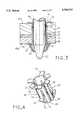
- FIG. 1is a perspective view of the rivet in its initial state
- FIG. 2is a vertical section view through a rivet installed in one of the parts for assembly
- FIG. 3is a vertical section view through a rivet installed in the parts to be assembled together, and after the rivet has been deformed;
- FIG. 4is a view similar to FIG. 1, showing the rivet in its deformed state
- FIG. 5is a vertical section view through one example of an assembly being fastened together using the rivet on an additional part and making use of the residual empty hole that is left in the rivet after it has been installed.
- the rivetmay be made by cutting, folding, and stamping sheet metal having resilient properties, such as a steel or a copper alloy.
- the rivetis constituted by a hollow cylindrical body 10 about an axis XX'. At its top end, the rivet is provided with a collar 14 which is connected to the top end 12 of the body 10 and extends outwardly therefrom, lying substantially in a plane perpendicular to the axis XX'.
- the collar 14is constituted by a single portion of sheet metal or by a plurality of segments 15, as shown in FIGS. 1 to 4.
- the collar 14is at a small angle to a plane perpendicular to the axis XX' of the body. More precisely, the collar is preferably constituted by a truncated cone whose half-angle at the apex lies in the range 75° to 90° .
- the body 10 and the collar 14are not continuous around their circumference. Each includes a slot, referenced 16 in the body 10 and 18 in the collar 14, the slot lying in a half-plane extending from the axis XX'.
- the body 10is provided with locking elements.
- locking elementsIn the example shown, there are three of them distributed at angular intervals of 120° about the axis XX'.
- the three locking elementsare identical, with only the elements 20 and 22 being visible in FIG. 1.
- Each locking elementis constituted by a strip 24 separated from the remainder of the body by axial cutouts 26 and 28. The ends of the strip 24 are connected to the top and bottom ends 12 and 13 respectively of the cylindrical body 10 of the rivet. In the rest position, the locking elements are constituted by the metal strips 24 which include folds.
- Each strip 24comprises a first portion 30 which is inclined relative to the axis XX', a second portion 32 which is substantially orthogonal to the axis XX', and a third portion 34 which is again inclined relative to the axis XX'. Overall, when at rest, each strip 24 projects into the inside of the cylindrical body 10 of the rivet.
- the edge 17 of the cylindrical body 10 defining the slot 16is preferably provided with spikes, e.g. two spikes referenced 36 and 38, which project into the slot 16. The function thereof is explained below.
- the cylindrical bodyincludes tongues 47 projecting out from the cylindrical body in its top end 12 adjacent to the collar 14.
- the sheet metal used for making the rivethas a thickness of 0.25 mm and the width of the slot 16 is about 0.35 mm.
- the other dimensions of the rivetdepend on the thicknesses of the parts to be assembled together and on the diameter of the assembly orifices therein.
- FIG. 2shows a first use of the rivet.
- the rivetis inserted firstly into the orifice 40 of the first part 44 to be fastened. Because of the projecting non-return tongues 47, the rivet is secured to the part 44. During such insertion, differences due to manufacturing tolerances are accommodated by crushing the spikes 36 and 38. This ensures that the rivet is automatically clamped and automatically centered in the orifices.
- the rivet as already secured to the part 44is inserted into the orifices 42 and 43 of the parts 45 and 46 by means of a robot or by hand. Since the locking elements 20 and 22 are inside the cylindrical body, such insertion can take place using a force that is close to zero.
- a finger 50is inserted inside the cylindrical body 10 by means of a manipulator, thereby opening out the locking elements 20, 22 of the rivet.
- the chamfered end 52 of the fingeracts on the first portions 30 of the locking elements.
- the effect of pushing in the finger 50is to cause the portion 30 to be deformed as shown in FIGS. 3 and 4 so as to become substantially axial.
- the second portion 32then projects outside the cylindrical body and bears against the bottom face 46a of the part 46, thereby locking the rivet in the orifices 40, 41, and 42. Manufacturing tolerances in the thicknesses of the parts 44, 45, and 46 are accommodated by small amounts of deformation in the collar 14 which is pressed against the top face 44a of the part 44.
- the rivetcan be inserted directly into all three orifices 40, 42, and 43 of the parts 44, 45, and 46.
- the orifice 40 of the top part 44it is necessary for the orifice 40 of the top part 44 to have a diameter that is slightly larger, given the presence of the projections 47. Thereafter, the locking elements are deformed as described above with reference to FIG. 3.
- this second method of rivet insertionit is also possible to make use of a rivet that does not have anti-return projecting tongues 47.
- the rivetmay be made of a material that conducts electricity. Under such circumstances, it serves not only to obtain mechanical fastening between the parts to be assembled together, but also to obtain an electrical connection therebetween.
- the rivetmay be made of a conductive metal sheet that is suitable for soldering, e.g. using a lead-tin alloy, thereby reinforcing the electrical continuity provided by the rivet made of a conductive material and also making disassembly of the assembled-together parts practically impossible once soldering has taken place.
- FIG. 5shows an improved embodiment of the rivet device enabling parts that have already been assembled together by means of the rivet of FIGS. 2 and 3 to be fixed as a unit on an additional part 54, e.g. a metal plate, which additional part likewise has an orifice 56.
- the rivet deviceincludes, in addition to the rivet proper, a standard screw 58 or a standard rivet, or any other equivalent mechanical fastener means which is engaged in the inside cylindrical orifice that remains inside the body 10 of the rivet.
- This orificeis completely empty because the locking elements 20, 22 are caused to project outside the cylindrical body after the finger 50 has passed through the rivet. It is necessary for the diameter of the orifice 56 to be large enough to receive the deformed locking elements.
- a nut 60 and a washer 62co-operate with the screw 58 so as to achieve mechanical fastening between the part 54 and the set of parts 44, 45, and 46 that have already been assembled together by means of the rivet.
Landscapes
- Engineering & Computer Science (AREA)
- General Engineering & Computer Science (AREA)
- Mechanical Engineering (AREA)
- Insertion Pins And Rivets (AREA)
- Connection Of Plates (AREA)
Abstract
Description
The present invention relates to a zero insertion force rivet device.
More precisely, the present invention relates to a rivet device for assembling together two or more parts provided with orifices in alignment to enable the parts to be fastened together by means of a rivet without it being necessary to exert significant force to put the rivet into place in the orifices.
In particular, in the field of mounting a surface mount type connector on printed circuit cards, it is necessary to have rivets that ensure adequate centering of the two parts to be assembled together while nevertheless ensuring that the two parts are securely fastened together in the rivet insertion direction.
When mounting a connector of this type on a card, it is common practice to use robots, in which case it is essential to avoid any need to exert significant force to put a connector that is prefitted with two rivets into place on the printed circuit card, since otherwise the robot will engage a safety cutout, i.e. it will stop the assembly operation. In addition, it is necessary for the resulting assembly to be capable of withstanding forces, in particular forces due to plugging and unplugging connection pins, and also forces due to possible mishandling.
An object of the present invention is to provide a rivet device that enables the parts that are to be assembled to be properly centered, that enables the parts to be clamped effectively against one another, and that requires only very limited force for inserting the rivet into the orifices provided through the parts.
To achieve this object, the rivet device of the invention is characterized in that it comprises:
a substantially tubular body having first and second ends;
an annular collar projecting from said first end outwardly from said body substantially in the plane orthogonal to the axis of said body; and
at least two locking elements formed in the body, each locking element being constituted by an elastically deformable strip cut out in said body, extending in the direction of the axis of the body, and having a first end secured to the first end of said body and a second end secured to the second end of said body, each strip having folds such that in an initial state a portion of said strip projects into the inside of said body, and such that in a deformed state said strip projects outside said body, the distance along the axis of said body between said collar and the projecting portions of said strips in the deformed position being substantially equal to the thickness of the set of parts to be assembled together as measured in the direction of the common axis of their orifices.
It will thus be understood that inserting the rivet device requires force that is very limited since the locking elements project into the inside of the rivet body, and not to the outside thereof. However, in a subsequent operation, the locking strips are deformed in such a manner as to cause a portion thereof to project outside the body, forming an interfering catch, thereby preventing the rivet from being extracted.
In a preferred embodiment, the collar is in the form of a truncated cone whose half-angle at the apex is less than 90°, the apex of the truncated cone lying outside said body.
It can thus be seen that during deformation of the locking strips to form the external projections, the collar can be deformed slightly to compensate for tolerances on the design thicknesses, and to ensure that the two parts are properly clamped together in the rivet insertion direction.
In another preferred characteristic, the body and the collar include a slot lying in a half-plane extending from the axis of the body, thereby enabling the diameter of the body to adapt to the diameter of the orifices in the parts. This disposition makes it possible to compensate for possible dispersion in the dimensions of the orifices of the parts to be assembled together and to ensure automatic centering of the two parts relative to the axis of the rivet.
Other characteristics and advantages of the present invention appear more clearly on reading the following description of an embodiment of the invention given by way of non-limiting example. The description refers to the accompanying drawings, in which:
FIG. 1 is a perspective view of the rivet in its initial state;
FIG. 2 is a vertical section view through a rivet installed in one of the parts for assembly;
FIG. 3 is a vertical section view through a rivet installed in the parts to be assembled together, and after the rivet has been deformed;
FIG. 4 is a view similar to FIG. 1, showing the rivet in its deformed state; and
FIG. 5 is a vertical section view through one example of an assembly being fastened together using the rivet on an additional part and making use of the residual empty hole that is left in the rivet after it has been installed.
With reference initially to FIG. 1, a preferred embodiment of the retaining rivet is initially described. The rivet may be made by cutting, folding, and stamping sheet metal having resilient properties, such as a steel or a copper alloy.
The rivet is constituted by a hollowcylindrical body 10 about an axis XX'. At its top end, the rivet is provided with acollar 14 which is connected to thetop end 12 of thebody 10 and extends outwardly therefrom, lying substantially in a plane perpendicular to the axis XX'. Thecollar 14 is constituted by a single portion of sheet metal or by a plurality ofsegments 15, as shown in FIGS. 1 to 4. Preferably, thecollar 14 is at a small angle to a plane perpendicular to the axis XX' of the body. More precisely, the collar is preferably constituted by a truncated cone whose half-angle at the apex lies in the range 75° to 90° . As can be seen, thebody 10 and thecollar 14 are not continuous around their circumference. Each includes a slot, referenced 16 in thebody collar 14, the slot lying in a half-plane extending from the axis XX'.
As can also be seen in FIG. 1, thebody 10 is provided with locking elements. In the example shown, there are three of them distributed at angular intervals of 120° about the axis XX'. The three locking elements are identical, with only theelements strip 24 separated from the remainder of the body byaxial cutouts strip 24 are connected to the top andbottom ends cylindrical body 10 of the rivet. In the rest position, the locking elements are constituted by themetal strips 24 which include folds. Eachstrip 24 comprises afirst portion 30 which is inclined relative to the axis XX', asecond portion 32 which is substantially orthogonal to the axis XX', and athird portion 34 which is again inclined relative to the axis XX'. Overall, when at rest, eachstrip 24 projects into the inside of thecylindrical body 10 of the rivet.
The figures show that theedge 17 of thecylindrical body 10 defining theslot 16 is preferably provided with spikes, e.g. two spikes referenced 36 and 38, which project into theslot 16. The function thereof is explained below. To assemble togetherparts respective orifices tongues 47 projecting out from the cylindrical body in itstop end 12 adjacent to thecollar 14.
In one embodiment, the sheet metal used for making the rivet has a thickness of 0.25 mm and the width of theslot 16 is about 0.35 mm. The other dimensions of the rivet depend on the thicknesses of the parts to be assembled together and on the diameter of the assembly orifices therein.
FIG. 2 shows a first use of the rivet.
In a first stage, the rivet is inserted firstly into theorifice 40 of thefirst part 44 to be fastened. Because of the projectingnon-return tongues 47, the rivet is secured to thepart 44. During such insertion, differences due to manufacturing tolerances are accommodated by crushing thespikes
During a second stage, the rivet as already secured to thepart 44 is inserted into theorifices parts locking elements
In a third stage, afinger 50 is inserted inside thecylindrical body 10 by means of a manipulator, thereby opening out thelocking elements end 52 of the finger acts on thefirst portions 30 of the locking elements. The effect of pushing in thefinger 50 is to cause theportion 30 to be deformed as shown in FIGS. 3 and 4 so as to become substantially axial. Thesecond portion 32 then projects outside the cylindrical body and bears against thebottom face 46a of thepart 46, thereby locking the rivet in theorifices parts collar 14 which is pressed against the top face 44a of thepart 44.
In a variant, the rivet can be inserted directly into all threeorifices parts orifice 40 of thetop part 44 to have a diameter that is slightly larger, given the presence of theprojections 47. Thereafter, the locking elements are deformed as described above with reference to FIG. 3. In this second method of rivet insertion, it is also possible to make use of a rivet that does not haveanti-return projecting tongues 47.
The rivet may be made of a material that conducts electricity. Under such circumstances, it serves not only to obtain mechanical fastening between the parts to be assembled together, but also to obtain an electrical connection therebetween.
Furthermore, the rivet may be made of a conductive metal sheet that is suitable for soldering, e.g. using a lead-tin alloy, thereby reinforcing the electrical continuity provided by the rivet made of a conductive material and also making disassembly of the assembled-together parts practically impossible once soldering has taken place.
FIG. 5 shows an improved embodiment of the rivet device enabling parts that have already been assembled together by means of the rivet of FIGS. 2 and 3 to be fixed as a unit on anadditional part 54, e.g. a metal plate, which additional part likewise has anorifice 56. To this end, the rivet device includes, in addition to the rivet proper, astandard screw 58 or a standard rivet, or any other equivalent mechanical fastener means which is engaged in the inside cylindrical orifice that remains inside thebody 10 of the rivet. This orifice is completely empty because thelocking elements finger 50 has passed through the rivet. It is necessary for the diameter of theorifice 56 to be large enough to receive the deformed locking elements. Anut 60 and awasher 62 co-operate with thescrew 58 so as to achieve mechanical fastening between thepart 54 and the set ofparts
Claims (10)
1. A rivet device for fastening a set of parts which, when assembled together, include orifices having a common axis, and which present a total given thickness, said rivet device comprising:
a member formed by a substantially tubular body having first and second ends;
an annular collar projecting from said first end outwardly from said body substantially in a plane orthogonal to an axis of said body; and
at least two locking elements formed in the body, each locking element being constituted by an elastically deformable strip cut out in said body and separated from said body by two cuts, said locking elements extending in a direction of the axis of the body, and having a first end secured to the first end of said body and a second end secured to the second end of said body, each strip having folds having two stable states, said folds being formed such that in an initial state said strip entirely projects into an inside of said body, and such that in a deformed state said strip is capable of projecting outside said body, a distance along the axis of said body between said collar and the projecting portions of said strips in the deformed position being substantially equal to the thickness of the set of parts to be assembled together as measured in a direction of the common axis of their orifices.
2. A rivet device according to claim 1, wherein said collar forms a truncated cone, with a semi-angle at an apex lying in a range of 75° to 90°, the apex of said truncated cone being outside said body.
3. A rivet device according to claim 1, wherein said body and said collar include a slot lying in a half-plane extending from the axis of said body, thereby enabling a diameter of said body to adapt to a diameter of said orifices.
4. A rivet device according to claim 3, wherein one of two edges of the slot formed in said body is provided with at least one deformable extension of a length that is shorter than the width of said slot in a plane orthogonal to the axis of said body.
5. A rivet device according to claim 1, wherein each locking element forming strip comprises, in its non-deformed state, a first folded portion at an angle with the axis of said body and extending from said first end of the strip, a second folded portion substantially orthogonal to the axis of said body, and a third folded portion connecting said second folded portion to said second end of the strip, and in its deformed state, said second and third folded portions project out from said cylindrical body, said second portion being substantially orthogonal to the axis of said body, whereby said parts to be fastened are clamped between said collar and said second folded portions.
6. A rivet device according to claim 1, wherein said body, said collar, and said strips, form a single part cut out from and folded in a single metal sheet having resilient properties.
7. A rivet device according to claim 1, wherein one of said first and second ends of the body which is closer to said collar includes elements projecting out from said body to enable the body to be secured in one of the parts to be assembled together.
8. A rivet device according to claim 1, made from a sheet of electrically conductive metal so as to ensure electrical continuity between the parts to be assembled together.
9. A rivet device according claim 1, made from a material that is suitable for soldering.
10. A rivet device according to claim 1, further including mechanical fastening means engagable in a cylindrical orifice of the cylindrical body to secure parts that have already been assembled together by the rivet body to an additional part.
Applications Claiming Priority (3)
| Application Number | Priority Date | Filing Date | Title |
|---|---|---|---|
| FR9212987 | 1992-10-23 | ||
| FR9212987AFR2697301B1 (en) | 1992-10-23 | 1992-10-23 | Rivet device with zero insertion force. |
| PCT/FR1993/001030WO1994010464A1 (en) | 1992-10-23 | 1993-10-20 | Zero insertion force rivet device |
Publications (1)
| Publication Number | Publication Date |
|---|---|
| US5704752Atrue US5704752A (en) | 1998-01-06 |
Family
ID=9435007
Family Applications (1)
| Application Number | Title | Priority Date | Filing Date |
|---|---|---|---|
| US08/325,171Expired - Fee RelatedUS5704752A (en) | 1992-10-23 | 1993-10-20 | Zero insertion force rivet device |
Country Status (4)
| Country | Link |
|---|---|
| US (1) | US5704752A (en) |
| EP (1) | EP0665925A1 (en) |
| FR (1) | FR2697301B1 (en) |
| WO (1) | WO1994010464A1 (en) |
Cited By (47)
| Publication number | Priority date | Publication date | Assignee | Title |
|---|---|---|---|---|
| US5848469A (en)* | 1996-09-26 | 1998-12-15 | The Budd Company | Vehicle frame with side/cross member joint |
| US5879099A (en)* | 1995-12-22 | 1999-03-09 | Mercedes-Benz Ag | Rigid connection of structural parts in the case of a motor vehicle and tool and method for establishing the connection |
| US6238127B1 (en)* | 1998-12-17 | 2001-05-29 | Western Sky Industries, Inc. | Pivot apparatus including a fastener and bushing assembly |
| US6488163B1 (en)* | 1999-10-01 | 2002-12-03 | Trn Business Trust | Knuckle coupler pin |
| EP0993083B1 (en)* | 1998-10-05 | 2003-01-08 | Fci | A contact clip, intended most notably for busbar systems |
| US20030119588A1 (en)* | 2001-12-20 | 2003-06-26 | Schlegelmann Joseph B. | Method and apparatus for servicing a staked universal joint |
| US6588997B1 (en)* | 2002-02-08 | 2003-07-08 | King Slide Works Co., Ltd. | Bolt fixing assembly |
| WO2003069971A2 (en) | 2002-02-15 | 2003-08-28 | Travis Mcclure | An expandable collet anchor system and method |
| US6663330B2 (en)* | 2000-07-05 | 2003-12-16 | Siemens Vdo Automotive, Inc. | Roll pin compression limiter |
| US20040013465A1 (en)* | 2002-07-16 | 2004-01-22 | Lapointe Larry P. | Oil-less rivet system for a reclining chair mechanism |
| US6688829B1 (en)* | 2002-12-04 | 2004-02-10 | Illinois Tool Works Inc. | Ceiling clip |
| US6688822B2 (en)* | 2001-09-07 | 2004-02-10 | Ritter Gmbh | Plastic injection anchoring sleeve |
| US6862777B2 (en) | 2002-07-16 | 2005-03-08 | La-Z-Boy Incorporated | Oil-less rivet system for a reclining chair mechanism |
| US20050207861A1 (en)* | 2004-03-22 | 2005-09-22 | Leatherman Barth A | Anchoring device |
| US20070036629A1 (en)* | 2005-08-10 | 2007-02-15 | Hung-Chin Hsu | Fast fasten and loose resistant bolt and nut structure |
| US20090010732A1 (en)* | 2007-07-02 | 2009-01-08 | Ejot Gmbh & Co. Kg | Fixing clip for joining two superimposed flat components |
| DE102009014847A1 (en)* | 2009-03-30 | 2010-10-14 | Autoliv Development Ab | Fastening device for securely fastening safety seat belt of belt retractor at vehicle structure, has cylindrical section whose inner diameter is dimensioned such that retainer is fastened to section by friction conclusive connection |
| US20110282396A1 (en)* | 2010-05-11 | 2011-11-17 | Warsaw Orthopedic, Inc. | Implant with deployable stabilizers |
| WO2014135557A1 (en)* | 2013-03-06 | 2014-09-12 | Walter Söhner GmbH & Co. KG | Clip contact element for a printed circuit board, and method for producing same |
| US20140259626A1 (en)* | 2013-03-15 | 2014-09-18 | Hendrickson Usa, L.L.C. | Systems and methods for improving bolted joints |
| US20140377031A1 (en)* | 2013-06-21 | 2014-12-25 | Steering Solutions Ip Holding Corporation | Self-locking insert |
| US20150198190A1 (en)* | 2014-01-13 | 2015-07-16 | Jeffrey D. Carnevali | Rod-to-tube adapter |
| US20160290390A1 (en)* | 2015-03-31 | 2016-10-06 | Saint-Gobain Performance Plastics Pampus Gmbh | Bearing with flange segments |
| CN107110186A (en)* | 2015-02-12 | 2017-08-29 | 啦唛喽股份公司 | Pin part, fixing device, the method for producing the method and fixing device for installing of pin part |
| US9816542B2 (en)* | 2013-09-30 | 2017-11-14 | A. Raymond Et Cie | Anchoring device |
| US9970468B2 (en) | 2009-04-13 | 2018-05-15 | Centrix, Inc. | Biased blind side temporary fasteners, systems and methods |
| US10001156B2 (en) | 2008-08-22 | 2018-06-19 | Centrix Inc. | Dynamic sleeve insert for use with a blind fastener system |
| US10094408B2 (en) | 2009-03-13 | 2018-10-09 | Centrix Inc. | Blind fastener with integrated anti-rotation feature, systems and methods |
| US20180294585A1 (en)* | 2017-04-11 | 2018-10-11 | Harwin Plc | Electrical socket |
| US20190002164A1 (en)* | 2015-08-07 | 2019-01-03 | Pacplus Co., Ltd. | Stopper |
| US20190024692A1 (en)* | 2016-03-03 | 2019-01-24 | Marc Serra | Fastening system and air handling unit comprising such a fastening system |
| US10190615B2 (en) | 2014-02-18 | 2019-01-29 | Centrix Aero, LLC | One piece screws for, and methods for making and using, blind side fasteners and systems with free spin feature |
| US20190097331A1 (en)* | 2017-09-25 | 2019-03-28 | Ge Aviation Systems Limited | Surface mount connector and method of forming a printed circuit board |
| US10260548B2 (en) | 2008-08-26 | 2019-04-16 | Centrix Inc. | Temporary fasteners |
| US10309456B2 (en)* | 2016-08-02 | 2019-06-04 | Saint-Gobain Performance Plastics Corporation | Bearing |
| US10378571B2 (en) | 2016-03-17 | 2019-08-13 | Centrix Inc. | Removable, single side fastener with ultra-low stack height grip range, components, and methods for making and using the same |
| US10465734B2 (en) | 2016-02-26 | 2019-11-05 | Centrix Inc. | Expandable collet bodies with sectional finger-based anti-rotation feature, clips, inserts and systems thereof |
| US10808422B2 (en) | 2017-02-27 | 2020-10-20 | Centrix Aero, LLC | Sensor pin |
| US10920812B2 (en) | 2017-03-09 | 2021-02-16 | Centrix Inc. | Fastener system with expandable ring |
| US10982701B2 (en) | 2016-04-20 | 2021-04-20 | Centrix Inc. | Single side temporary fastener with constant pressure feature |
| US11193517B2 (en) | 2017-09-14 | 2021-12-07 | Centrix Inc. | Fastener system |
| US11231057B2 (en) | 2015-02-13 | 2022-01-25 | Centrix Inc. | Hole alignment tool with compliance zone feature |
| US20220200255A1 (en)* | 2020-12-17 | 2022-06-23 | Vitesco Technologies GmbH | High-voltage junction box for an electrically driven vehicle and electrically driven vehicle |
| US11374366B2 (en) | 2020-06-19 | 2022-06-28 | Lear Corporation | System and method for providing an electrical ground connection for a circuit assembly |
| US11646514B2 (en) | 2020-08-10 | 2023-05-09 | Lear Corporation | Surface mount technology terminal header and method for providing an electrical connection to a printed circuit board |
| US11692574B2 (en) | 2017-09-14 | 2023-07-04 | Centrix Inc. | Fastener system |
| US11706867B2 (en) | 2021-01-27 | 2023-07-18 | Lear Corporation | System and method for providing an electrical ground connection for a circuit assembly |
Families Citing this family (5)
| Publication number | Priority date | Publication date | Assignee | Title |
|---|---|---|---|---|
| GB9617453D0 (en)* | 1996-08-17 | 1996-10-02 | Emhart Inc | Improved rivet assembly |
| DE102005030435A1 (en)* | 2005-06-30 | 2007-01-04 | William Prym Gmbh & Co. Kg | mounting sleeve |
| DE102012024762A1 (en)* | 2012-12-19 | 2014-06-26 | Wabco Gmbh | Clamping bush for frictional fixation and adjustment of e.g. rod sensor in bore of supporting portion, has two resilient tongues connected at one side of the bush, such that their heads are freely movable, and a fine adjusting tongue |
| DE102013218659A1 (en)* | 2013-09-18 | 2015-03-19 | Fränkische Industrial Pipes GmbH & Co. KG | Sensor system for an energy unit |
| DE102014101968A1 (en)* | 2014-02-17 | 2015-08-20 | Endress + Hauser Wetzer Gmbh + Co. Kg | Measuring device and measuring insert for such a measuring device |
Citations (15)
| Publication number | Priority date | Publication date | Assignee | Title |
|---|---|---|---|---|
| GB149946A (en)* | 1919-08-20 | 1921-06-16 | Budd Edward G Mfg Co | Improvements in rivets and process of making same |
| US2340423A (en)* | 1942-09-03 | 1944-02-01 | Jr Bernard T O'shaughnessy | Expansion rivet |
| US2400142A (en)* | 1944-03-17 | 1946-05-14 | Tinnerman Products Inc | Fastening device |
| US2826110A (en)* | 1952-01-02 | 1958-03-11 | Jerome H Lemelson | Hollow sheet metal rivet with reinforcing work engaging shoulders |
| US3232161A (en)* | 1961-08-22 | 1966-02-01 | Ft Products Ltd | Blind fasteners |
| US3269251A (en)* | 1964-08-17 | 1966-08-30 | Bass Henry James | Threaded inserts with sliding segmental securing means |
| DE1940299A1 (en)* | 1969-08-07 | 1971-02-18 | Inhoffen Hubertus Von | Blind fasteners, in particular for holes accessible from one side and for the production of a joint connection |
| US3710674A (en)* | 1970-12-18 | 1973-01-16 | Meteor Res Ltd | Expandable fastener |
| US4244661A (en)* | 1979-07-23 | 1981-01-13 | Mcdonnell Douglas Corporation | Fastener means and joint for laminates |
| DE3212160A1 (en)* | 1982-04-01 | 1983-10-06 | Ernst Hans Hellmut | Connecting element with a clip effect |
| US4927287A (en)* | 1988-06-28 | 1990-05-22 | Nifco, Inc. | Fastener for fastening plates together |
| US5083942A (en)* | 1991-02-13 | 1992-01-28 | E. I. Du Pont De Nemours And Company | Fish hook hold-downs |
| US5259689A (en)* | 1990-10-26 | 1993-11-09 | Gkn Cardantec International | Component connecting means especially flange connecting means |
| US5261772A (en)* | 1990-10-13 | 1993-11-16 | Camloc Gmbh | Device to connect detachably two components |
| US5266052A (en)* | 1992-10-29 | 1993-11-30 | Penn Engineering & Manufacturing Corp. | Circuit board hold-down fastener |
- 1992
- 1992-10-23FRFR9212987Apatent/FR2697301B1/ennot_activeExpired - Fee Related
- 1993
- 1993-10-20WOPCT/FR1993/001030patent/WO1994010464A1/ennot_activeApplication Discontinuation
- 1993-10-20USUS08/325,171patent/US5704752A/ennot_activeExpired - Fee Related
- 1993-10-20EPEP93924097Apatent/EP0665925A1/ennot_activeWithdrawn
Patent Citations (15)
| Publication number | Priority date | Publication date | Assignee | Title |
|---|---|---|---|---|
| GB149946A (en)* | 1919-08-20 | 1921-06-16 | Budd Edward G Mfg Co | Improvements in rivets and process of making same |
| US2340423A (en)* | 1942-09-03 | 1944-02-01 | Jr Bernard T O'shaughnessy | Expansion rivet |
| US2400142A (en)* | 1944-03-17 | 1946-05-14 | Tinnerman Products Inc | Fastening device |
| US2826110A (en)* | 1952-01-02 | 1958-03-11 | Jerome H Lemelson | Hollow sheet metal rivet with reinforcing work engaging shoulders |
| US3232161A (en)* | 1961-08-22 | 1966-02-01 | Ft Products Ltd | Blind fasteners |
| US3269251A (en)* | 1964-08-17 | 1966-08-30 | Bass Henry James | Threaded inserts with sliding segmental securing means |
| DE1940299A1 (en)* | 1969-08-07 | 1971-02-18 | Inhoffen Hubertus Von | Blind fasteners, in particular for holes accessible from one side and for the production of a joint connection |
| US3710674A (en)* | 1970-12-18 | 1973-01-16 | Meteor Res Ltd | Expandable fastener |
| US4244661A (en)* | 1979-07-23 | 1981-01-13 | Mcdonnell Douglas Corporation | Fastener means and joint for laminates |
| DE3212160A1 (en)* | 1982-04-01 | 1983-10-06 | Ernst Hans Hellmut | Connecting element with a clip effect |
| US4927287A (en)* | 1988-06-28 | 1990-05-22 | Nifco, Inc. | Fastener for fastening plates together |
| US5261772A (en)* | 1990-10-13 | 1993-11-16 | Camloc Gmbh | Device to connect detachably two components |
| US5259689A (en)* | 1990-10-26 | 1993-11-09 | Gkn Cardantec International | Component connecting means especially flange connecting means |
| US5083942A (en)* | 1991-02-13 | 1992-01-28 | E. I. Du Pont De Nemours And Company | Fish hook hold-downs |
| US5266052A (en)* | 1992-10-29 | 1993-11-30 | Penn Engineering & Manufacturing Corp. | Circuit board hold-down fastener |
Cited By (93)
| Publication number | Priority date | Publication date | Assignee | Title |
|---|---|---|---|---|
| US5879099A (en)* | 1995-12-22 | 1999-03-09 | Mercedes-Benz Ag | Rigid connection of structural parts in the case of a motor vehicle and tool and method for establishing the connection |
| US6092287A (en)* | 1995-12-22 | 2000-07-25 | Daimlerchrysler Ag | Rigid connection of structural parts in the case of a motor vehicle and method for establishing the connection |
| US6122812A (en)* | 1995-12-22 | 2000-09-26 | Daimlerchrysler Ag | Rigid connection of structural parts in the case of a motor vehicle and tool for establishing the connection |
| US5848469A (en)* | 1996-09-26 | 1998-12-15 | The Budd Company | Vehicle frame with side/cross member joint |
| EP0993083B1 (en)* | 1998-10-05 | 2003-01-08 | Fci | A contact clip, intended most notably for busbar systems |
| US6238127B1 (en)* | 1998-12-17 | 2001-05-29 | Western Sky Industries, Inc. | Pivot apparatus including a fastener and bushing assembly |
| US6488163B1 (en)* | 1999-10-01 | 2002-12-03 | Trn Business Trust | Knuckle coupler pin |
| US6663330B2 (en)* | 2000-07-05 | 2003-12-16 | Siemens Vdo Automotive, Inc. | Roll pin compression limiter |
| US6804872B2 (en)* | 2000-07-05 | 2004-10-19 | Siemens Vdo Automotive Inc. | Method of forming a roll pin compression limiter |
| US6688822B2 (en)* | 2001-09-07 | 2004-02-10 | Ritter Gmbh | Plastic injection anchoring sleeve |
| US20030119588A1 (en)* | 2001-12-20 | 2003-06-26 | Schlegelmann Joseph B. | Method and apparatus for servicing a staked universal joint |
| US6588997B1 (en)* | 2002-02-08 | 2003-07-08 | King Slide Works Co., Ltd. | Bolt fixing assembly |
| US20050169726A1 (en)* | 2002-02-15 | 2005-08-04 | Mcclure Travis D. | Expandable collet anchor system and method |
| WO2003069971A2 (en) | 2002-02-15 | 2003-08-28 | Travis Mcclure | An expandable collet anchor system and method |
| US20090155014A1 (en)* | 2002-02-15 | 2009-06-18 | Mcclure Travis D | Expandable collet anchor system and method |
| EP1483513A4 (en)* | 2002-02-15 | 2006-04-26 | Travis Mcclure | EXPANDABLE CLIP SLEEVE ANCHORING SYSTEM, COMPONENTS THEREOF AND MANUFACTURING AND USE METHOD THEREFOR |
| EP2275692A3 (en)* | 2002-02-15 | 2012-01-25 | Travis Mcclure | Method for using an expandable collet anchor system |
| US8075234B2 (en)* | 2002-02-15 | 2011-12-13 | Mcclure Travis D | Expandable collet anchor system and method |
| EP2275692B2 (en)† | 2002-02-15 | 2021-01-20 | Centrix Inc. | Method for using an expandable collet anchor system |
| US20040208695A1 (en)* | 2002-07-16 | 2004-10-21 | Lapointe Larry P. | Oil-less rivet system for a reclining chair mechanism |
| US6862777B2 (en) | 2002-07-16 | 2005-03-08 | La-Z-Boy Incorporated | Oil-less rivet system for a reclining chair mechanism |
| US6939076B2 (en)* | 2002-07-16 | 2005-09-06 | La-Z-Boy Incorporated | Oil-less rivet system for a reclining chair mechanism |
| US20040013465A1 (en)* | 2002-07-16 | 2004-01-22 | Lapointe Larry P. | Oil-less rivet system for a reclining chair mechanism |
| US7101110B2 (en) | 2002-07-16 | 2006-09-05 | La-Z-Boy Incorporated | Oil-less rivet system for a reclining chair mechanism |
| US6688829B1 (en)* | 2002-12-04 | 2004-02-10 | Illinois Tool Works Inc. | Ceiling clip |
| US20050207861A1 (en)* | 2004-03-22 | 2005-09-22 | Leatherman Barth A | Anchoring device |
| US7344346B2 (en)* | 2005-08-10 | 2008-03-18 | Hung-Chih Hsu | Fast fasten and loose resistant bolt and nut structure |
| US20070036629A1 (en)* | 2005-08-10 | 2007-02-15 | Hung-Chin Hsu | Fast fasten and loose resistant bolt and nut structure |
| US20090010732A1 (en)* | 2007-07-02 | 2009-01-08 | Ejot Gmbh & Co. Kg | Fixing clip for joining two superimposed flat components |
| US10001156B2 (en) | 2008-08-22 | 2018-06-19 | Centrix Inc. | Dynamic sleeve insert for use with a blind fastener system |
| US11434951B2 (en) | 2008-08-26 | 2022-09-06 | Centrix Inc. | Temporary fasteners |
| US10260548B2 (en) | 2008-08-26 | 2019-04-16 | Centrix Inc. | Temporary fasteners |
| US10094408B2 (en) | 2009-03-13 | 2018-10-09 | Centrix Inc. | Blind fastener with integrated anti-rotation feature, systems and methods |
| US11092181B2 (en) | 2009-03-13 | 2021-08-17 | Centrix Inc. | Blind fastener with integrated anti-rotation feature, systems and methods |
| US10612578B2 (en) | 2009-03-13 | 2020-04-07 | Centrix Inc. | Blind fastener with integrated anti-rotation feature, systems and methods |
| DE102009014847A1 (en)* | 2009-03-30 | 2010-10-14 | Autoliv Development Ab | Fastening device for securely fastening safety seat belt of belt retractor at vehicle structure, has cylindrical section whose inner diameter is dimensioned such that retainer is fastened to section by friction conclusive connection |
| US11655839B2 (en) | 2009-04-13 | 2023-05-23 | Centrix Inc. | Biased blind side temporary fasteners, systems and methods |
| US10473135B2 (en) | 2009-04-13 | 2019-11-12 | Centrix Inc. | Biased blind side temporary fasteners, systems and methods |
| US9970468B2 (en) | 2009-04-13 | 2018-05-15 | Centrix, Inc. | Biased blind side temporary fasteners, systems and methods |
| US20110282396A1 (en)* | 2010-05-11 | 2011-11-17 | Warsaw Orthopedic, Inc. | Implant with deployable stabilizers |
| US8486120B2 (en)* | 2010-05-11 | 2013-07-16 | Warsaw Orthopedic, Inc. | Implant with deployable stabilizers |
| WO2014135557A1 (en)* | 2013-03-06 | 2014-09-12 | Walter Söhner GmbH & Co. KG | Clip contact element for a printed circuit board, and method for producing same |
| US20140259626A1 (en)* | 2013-03-15 | 2014-09-18 | Hendrickson Usa, L.L.C. | Systems and methods for improving bolted joints |
| US9568033B2 (en)* | 2013-03-15 | 2017-02-14 | Hendrickson Usa, L.L.C. | Systems and methods for improving bolted joints |
| US10544821B2 (en) | 2013-06-21 | 2020-01-28 | Steering Solutions Ip Holding Corporation | Self-locking insert |
| US20140377031A1 (en)* | 2013-06-21 | 2014-12-25 | Steering Solutions Ip Holding Corporation | Self-locking insert |
| US9506495B2 (en)* | 2013-06-21 | 2016-11-29 | Steering Solutions Ip Holding Corporation | Self-locking insert |
| US9816542B2 (en)* | 2013-09-30 | 2017-11-14 | A. Raymond Et Cie | Anchoring device |
| RU2682809C2 (en)* | 2013-09-30 | 2019-03-21 | А. Раймон Э Сие | Anchoring device |
| US9360035B2 (en)* | 2014-01-13 | 2016-06-07 | Jeffrey D. Carnevali | Rod-to-tube adapter |
| US20150198190A1 (en)* | 2014-01-13 | 2015-07-16 | Jeffrey D. Carnevali | Rod-to-tube adapter |
| US12129882B2 (en) | 2014-02-18 | 2024-10-29 | Centrix Aerospace Llc | One piece screws for, and methods for making and using, blind side fasteners and systems with free spin feature |
| USD844421S1 (en) | 2014-02-18 | 2019-04-02 | Centrix Aero, LLC | Single sided fastener |
| US11746816B2 (en) | 2014-02-18 | 2023-09-05 | Centrix Inc. | One piece screws for, and methods for making and using, blind side fasteners and systems with free spin feature |
| US11639734B2 (en) | 2014-02-18 | 2023-05-02 | Centrix Inc. | One piece screws for, and methods for making and using, blind side fasteners and systems with free spin feature |
| US10190615B2 (en) | 2014-02-18 | 2019-01-29 | Centrix Aero, LLC | One piece screws for, and methods for making and using, blind side fasteners and systems with free spin feature |
| US10830269B2 (en) | 2014-02-18 | 2020-11-10 | Centrix Inc. | One piece screws for, and methods for making and using, blind side fasteners and systems with free spin feature |
| CN107110186B (en)* | 2015-02-12 | 2019-05-28 | 啦唛喽股份公司 | Pin part, fixed device, produces the method for pin part and the method for fixing device for installing |
| US10385897B2 (en) | 2015-02-12 | 2019-08-20 | Lamello Ag | Dowel element, fastening device, method for producing a dowel element, and method for installing a fastening device |
| CN107110186A (en)* | 2015-02-12 | 2017-08-29 | 啦唛喽股份公司 | Pin part, fixing device, the method for producing the method and fixing device for installing of pin part |
| US11231057B2 (en) | 2015-02-13 | 2022-01-25 | Centrix Inc. | Hole alignment tool with compliance zone feature |
| US20160290390A1 (en)* | 2015-03-31 | 2016-10-06 | Saint-Gobain Performance Plastics Pampus Gmbh | Bearing with flange segments |
| US9771973B2 (en)* | 2015-03-31 | 2017-09-26 | Saint-Gobain Performance Plastics Pampus Gmbh | Bearing with flange segments |
| US10479561B2 (en)* | 2015-08-07 | 2019-11-19 | Pacplus Co., Ltd. | Stopper |
| US20190002164A1 (en)* | 2015-08-07 | 2019-01-03 | Pacplus Co., Ltd. | Stopper |
| US12378987B2 (en) | 2016-02-26 | 2025-08-05 | Centrix Aerospace Llc | Expandable collet bodies with sectional finger-based anti-rotation feature, clips inserts and systems thereof |
| USD872553S1 (en) | 2016-02-26 | 2020-01-14 | Centrix, Inc. | Expandable collet body |
| US11460066B2 (en) | 2016-02-26 | 2022-10-04 | Centrix Inc. | Expandable collet bodies with sectional finger-based anti-rotation feature, clips, inserts and systems thereof |
| USD871876S1 (en) | 2016-02-26 | 2020-01-07 | Centrix, Inc. | Expandable collet body |
| US10465734B2 (en) | 2016-02-26 | 2019-11-05 | Centrix Inc. | Expandable collet bodies with sectional finger-based anti-rotation feature, clips, inserts and systems thereof |
| US11692580B2 (en) | 2016-02-26 | 2023-07-04 | Centrix Inc. | Expandable collet bodies with sectional finger-based anti-rotation feature, clips, inserts and systems thereof |
| USD945862S1 (en) | 2016-02-26 | 2022-03-15 | Centrix Inc. | Sleeve insert |
| US11898590B2 (en) | 2016-02-26 | 2024-02-13 | Centrix Inc. | Expandable collet bodies with sectional finger-based anti-rotation feature, clips, inserts and systems thereof |
| US10941800B2 (en)* | 2016-03-03 | 2021-03-09 | Carrier Corporation | Fastening system and air handling unit comprising such a fastening system |
| US20190024692A1 (en)* | 2016-03-03 | 2019-01-24 | Marc Serra | Fastening system and air handling unit comprising such a fastening system |
| US10378571B2 (en) | 2016-03-17 | 2019-08-13 | Centrix Inc. | Removable, single side fastener with ultra-low stack height grip range, components, and methods for making and using the same |
| US11608848B2 (en) | 2016-04-20 | 2023-03-21 | Centrix Inc. | Single side temporary fastener with constant pressure feature |
| US10982701B2 (en) | 2016-04-20 | 2021-04-20 | Centrix Inc. | Single side temporary fastener with constant pressure feature |
| US10309456B2 (en)* | 2016-08-02 | 2019-06-04 | Saint-Gobain Performance Plastics Corporation | Bearing |
| US10808422B2 (en) | 2017-02-27 | 2020-10-20 | Centrix Aero, LLC | Sensor pin |
| US10920812B2 (en) | 2017-03-09 | 2021-02-16 | Centrix Inc. | Fastener system with expandable ring |
| US20180294585A1 (en)* | 2017-04-11 | 2018-10-11 | Harwin Plc | Electrical socket |
| US10573983B2 (en)* | 2017-04-11 | 2020-02-25 | Harwin Plc | Female electrical socket configuration suitable for use with a PCB |
| EP3389143A1 (en)* | 2017-04-11 | 2018-10-17 | Harwin PLC | Electrical socket |
| US11193517B2 (en) | 2017-09-14 | 2021-12-07 | Centrix Inc. | Fastener system |
| US11692574B2 (en) | 2017-09-14 | 2023-07-04 | Centrix Inc. | Fastener system |
| US12117029B2 (en) | 2017-09-14 | 2024-10-15 | Centrix Aerospace Llc | Fastener system |
| US20190097331A1 (en)* | 2017-09-25 | 2019-03-28 | Ge Aviation Systems Limited | Surface mount connector and method of forming a printed circuit board |
| US11374366B2 (en) | 2020-06-19 | 2022-06-28 | Lear Corporation | System and method for providing an electrical ground connection for a circuit assembly |
| US11646514B2 (en) | 2020-08-10 | 2023-05-09 | Lear Corporation | Surface mount technology terminal header and method for providing an electrical connection to a printed circuit board |
| US11870224B2 (en)* | 2020-12-17 | 2024-01-09 | Vitesco Technologies GmbH | High-voltage junction box for an electrically driven vehicle and electrically driven vehicle |
| US20220200255A1 (en)* | 2020-12-17 | 2022-06-23 | Vitesco Technologies GmbH | High-voltage junction box for an electrically driven vehicle and electrically driven vehicle |
| US11706867B2 (en) | 2021-01-27 | 2023-07-18 | Lear Corporation | System and method for providing an electrical ground connection for a circuit assembly |
Also Published As
| Publication number | Publication date |
|---|---|
| FR2697301B1 (en) | 1995-01-13 |
| FR2697301A1 (en) | 1994-04-29 |
| EP0665925A1 (en) | 1995-08-09 |
| WO1994010464A1 (en) | 1994-05-11 |
Similar Documents
| Publication | Publication Date | Title |
|---|---|---|
| US5704752A (en) | Zero insertion force rivet device | |
| EP0898792B1 (en) | Miniature card edge clip | |
| EP0516023B1 (en) | Pylon actuated locking eyelet | |
| US5074807A (en) | Component holding device | |
| US6315620B1 (en) | System, method, and device for a pre-loaded straddle mounted connector assembly | |
| CA2165605C (en) | Resilient snap fitting retainer for printed circuit board mounting or the like | |
| EP0872917B1 (en) | A card connector | |
| JPH02503846A (en) | Electrical connectors and circuit board locking devices used therein | |
| JP3985570B2 (en) | Electrical junction box | |
| EP0668639A1 (en) | Bulb socket | |
| EP1122825B1 (en) | Substrate mount type terminal | |
| EP0432368A1 (en) | Electrical connector with attachment for automatically shorting select conductors upon disconnection of connector | |
| US5403195A (en) | Socket having an auxiliary electrical component mounted thereon | |
| US5401187A (en) | Electrical connector hold down anchor apparatus | |
| HK95088A (en) | Electrical terminal with cavity compensator | |
| US5542860A (en) | Electrical connector with mounting post | |
| EP0828317B1 (en) | Connector for use with substrates | |
| US6592405B1 (en) | Latch for ground shield of an electrical connector | |
| US20070012478A1 (en) | Contact spring assembly | |
| US5224885A (en) | Low profile dual beam contact | |
| US6267607B1 (en) | Anti-rotation ground clip for faceplates | |
| US5761047A (en) | Retaining support for electrical assembly having ribs extending from housing | |
| US5655932A (en) | Filter plug connector having a shield housing | |
| US5441425A (en) | Electrical connector with through condenser | |
| JPH0689760A (en) | connector |
Legal Events
| Date | Code | Title | Description |
|---|---|---|---|
| AS | Assignment | Owner name:AMPHENOL SOCAPEX, FRANCE Free format text:ASSIGNMENT OF ASSIGNORS INTEREST;ASSIGNOR:LOGEROT, BERNARD;REEL/FRAME:007578/0880 Effective date:19950505 | |
| FPAY | Fee payment | Year of fee payment:4 | |
| REMI | Maintenance fee reminder mailed | ||
| LAPS | Lapse for failure to pay maintenance fees | ||
| STCH | Information on status: patent discontinuation | Free format text:PATENT EXPIRED DUE TO NONPAYMENT OF MAINTENANCE FEES UNDER 37 CFR 1.362 | |
| FP | Lapsed due to failure to pay maintenance fee | Effective date:20060106 |