US5704686A - Gliding reclining chair - Google Patents
Gliding reclining chairDownload PDFInfo
- Publication number
- US5704686A US5704686AUS08/666,655US66665596AUS5704686AUS 5704686 AUS5704686 AUS 5704686AUS 66665596 AUS66665596 AUS 66665596AUS 5704686 AUS5704686 AUS 5704686A
- Authority
- US
- United States
- Prior art keywords
- links
- base
- link
- chair
- legrest
- Prior art date
- Legal status (The legal status is an assumption and is not a legal conclusion. Google has not performed a legal analysis and makes no representation as to the accuracy of the status listed.)
- Expired - Lifetime
Links
Images


Classifications
- A—HUMAN NECESSITIES
- A47—FURNITURE; DOMESTIC ARTICLES OR APPLIANCES; COFFEE MILLS; SPICE MILLS; SUCTION CLEANERS IN GENERAL
- A47C—CHAIRS; SOFAS; BEDS
- A47C1/00—Chairs adapted for special purposes
- A47C1/02—Reclining or easy chairs
- A47C1/031—Reclining or easy chairs having coupled concurrently adjustable supporting parts
- A47C1/034—Reclining or easy chairs having coupled concurrently adjustable supporting parts the parts including a leg-rest or foot-rest
- A47C1/035—Reclining or easy chairs having coupled concurrently adjustable supporting parts the parts including a leg-rest or foot-rest in combination with movably coupled seat and back-rest, i.e. the seat and back-rest being movably coupled in such a way that the extension mechanism of the foot-rest is actuated at least by the relative movements of seat and backrest
- A47C1/0355—Reclining or easy chairs having coupled concurrently adjustable supporting parts the parts including a leg-rest or foot-rest in combination with movably coupled seat and back-rest, i.e. the seat and back-rest being movably coupled in such a way that the extension mechanism of the foot-rest is actuated at least by the relative movements of seat and backrest actuated by linkages, e.g. lazy-tongs mechanisms
Definitions
- rocker camson which the chair mechanism is mounted.
- the rocker camsare supported on rails or rail regions of a base, and locks are usually provided for restricting or preventing rocking of the rocker cams on the rails if the legrest has been thrust sufficiently to lift the user's feet off the floor.
- the rocker cams on railsprovides a distinctive arc to the rocking motion of the user in the chair.
- the conventional rocking motionimposes restrictions on styling, including seat height.
- the flatter arching motion provided by a porch glideris more comfortable and less disconcerting than the motion provided by rocker cams rocking on rails or another flat surface. A shorter user can glide without their feet being lifted from the floor.
- rocker locks conventionally provided on rocker reclinersoften involve linkages which must pivot when the chair is meant to rock, or landing gear that can disconcertingly engage the base.
- a gliding reclining chairhas a base, on which a preferably three-position recliner chair mechanism is suspended by two short glider links on each side.
- the upper and lower pivot joints of the glider linksare ball bearing-type joints, for ease of gliding.
- the handle for thrusting and retracting the legrestinterconnects and associates the two side linkages, so that they act in coordination.
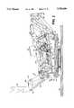
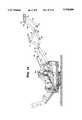
- FIG. 1is a perspective view of a gliding reclining chair embodying a preferred embodiment of the present invention, shown from the front and right side, with the legrest fully extended, and the backrest erect, in the intermediate, TV position of the chair.
- FIG. 2-16the upholstered backrest, seat and arm frame unit, and legrest are omitted.
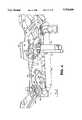
- FIG. 2is a longitudinal sectional view of the chair, looking from the omitted right side at the inner face of the left side, with the legrest fully retracted and the suspended structure of the chair at its natural rest position;
- FIG. 3is a perspective view of the chair from the right and above, in its FIG. 2 position;
- FIG. 4is a larger scale fragmentary perspective view of a portion of the chair as shown in FIG. 3;
- FIG. 5is a perspective view of the chair from the left and above, in its FIG. 2 position;
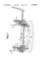
- FIG. 6is a rear elevational view of the chair in its FIG. 2 position
- FIG. 7is a perspective view of the chair from the rear, from a more elevated viewpoint than FIG. 6, showing the chair in its FIG. 2 position;
- FIG. 8is a view similar to FIG. 2, but showing suspended structure of the chair fully glided backward;
- FIG. 9is a view similar to FIG. 2, but showing the suspended structure of the chair fully glided forward;
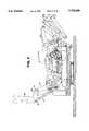
- FIG. 10is a longitudinal sectional view of the chair, looking from the omitted right side at the inner face of the left side, with the legrest fully extended, the back erect, and glide blocked, in the intermediate, TV position which is also depicted in FIG. 1;
- FIG. 11is a perspective view similar to FIG. 3, but showing the chair in its FIG. 1 position;
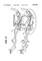
- FIG. 12is a larger scale fragmentary perspective view of a portion of the chair as shown in FIG. 11;
- FIG. 13is a perspective view similar to FIG. 5, but showing the chair in its FIG. 1 position;
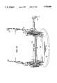
- FIG. 14is a top plan view of the chair in its FIG. 1 position
- FIG. 15is a perspective view similar to FIG. 7, but showing the chair in its FIG. 1 position;
- FIG. 16is a longitudinal sectional view of the chair, similar to FIGS. 2, 8, 9 and 10, but showing the chair with the legrest fully extended and the back fully reclined.
- the chair 10 of the preferred embodimentis a 3-position gliding reclining chair having a mechanism 12 mounted on a base 14 and having mounted thereon an upholstered seat and arm frame unit 16, an upholstered back 18, and an upholstered legrest, including a primary legrest 20 and a secondary legrest 22.
- an ottomanis a synonym for a legrest.
- the base 14is a swivel base which includes an upper, rotary base plate 24, a rotary joint 26 and a lower, stationary base 28.
- This type of baseis well known in the art.
- the features 26 and 28are omitted, so that the base 14 is provided by an analog of the plate 24, which is stationary in use and may be different in appearance (e.g., be legs or rails or a rectangular plate, or made of metal).
- the chair of the inventionmay be manufactured of conventional materials, using conventional techniques.
- the mechanism 12may be largely made of pieces sheared or punched from steel plate, drilled, bent and painted, e.g., flat black.
- Fixed connectionsmay be provided by rivets through aligned holes, stops by pins fixed in holes so as to project, and pivots by nut-and-bolt assemblies installed through aligned holes, or by rivets provided with washer-like spaces, e.g., made of steel or nylon provided between the joined links.
- rivets and pivotsprovide transverse, horizontal axis joints.
- left and rightas used, are given from the perspective of a person sitting in the chair.
- medialmeans at or towards the imaginary vertical centerline plane bisecting the left from the right of the chair, and lateral refers to the direction leftwards or rightwards away from the imaginary vertical centerline plane.
- the upper base 24is made of wood, e.g., a sheet of plywood, it could be fabricated at least in part of steel parts assembled and joined.
- outboard and outsiderefer to features that are relatively away from the imaginary vertical medial plane
- inboard and insiderefer to features that are relatively towards the imaginary vertical medial plane
- the mechanism 12is preferably manufactured as mirror image left and right side linkages 30, 32 some corresponding elements of which are joined, e.g., by a transverse bar or square-sectioned tube 34 and a torque tube 36.
- the joining of the side linkages by these featurescan be accomplished before or after the side linkages are mounted to the chair base.
- parts of the basee.g., the brackets 38, may be actually preassembled to the mechanism.
- the base or upper base plate 24is shown provided at the left and right, near the front and rear with four L-shaped brackets 38, each having a lower horizontal flange 40 and an outer, vertical flange 42. It is from upper pivot joints 44 provided at the upper ends of the flanges 42 that the mechanism 12 is glidingly, hangingly suspended on the base, by means of forward and rear hanger links 46, 48, via lower pivot joints 50.
- the upper and lower pivot joints 44, 50preferably incorporate annular ball bearing races, so that the pivoting action about the respective pivot axis is especially freely acting. Suitable ball bearing joints are widely commercially available.
- the hanger linksare preferably short, e.g., so that there is about 4.0 inches (10.2 cm) between the upper and lower pivot joints.
- the hanger links on the same side of the chairare preferably concavely arcuate toward one another in side profile.
- the lower pivot jointsare preferably about 10.25 inches (25.4 cm) apart, and the upper pivot joints about 2.5 inches (6.4 cm) further apart than the lower pivot joints. In other words, on each side, the lower pivot joints of the glider hanging links are preferably somewhat closer together than are the upper pivot joints.
- the vertical flanges 42 of the base rear corner brackets 38are shown having laterally protruding stop pins 52, provided with nylon sleeves, grommets or bumpers.
- each rear hanging linkforwardly of the lower pivot joint, each rear hanging link includes a medially directed generally vertical stop flange 54.
- the remainder of the mechanism 12could be adapted from a pre-existing mechanism. Some parts shown made of two pieces riveted together, could be fabricated as one piece, and vice versa.
- Each side linkageis shown using a main plate 56. It is mainly disposed in vertical planes, with more medial lower portion and a more lateral upper portion, integrally joined at a generally horizontal shoulder, a central part of the lower portion being cut prior to bending the shoulder, so that it remains in the plane of the shoulder to provide a medially directed tab 58.
- the transverse bar 34is secured at its opposite ends to the respective side linkage tabs 58.
- In-turned horizontal flangesare centrally provided on upper edges of the plates 56 at 60 to serve as guards to prevent underlying pivoted structure from cutting or interfering with the underside of the seat and arm frame unit.
- the rear lower pivot joints 50 of the hanger links 48mount to rear portions of the lower portions of the main plate 56 and the front lower pivot joints 50 of the hanger links 46 mount to front portions of the lower portions of the main plate 56.
- Each side linkagefurther includes a main carrier link 64 of substantial longitudinal extent.
- Each side linkageincludes towards its front end a respective pantographic linkage system for mounting a legrest for being thrust (in the TV position) and restricted (in the erect position of the chair).
- a legrestfor being thrust (in the TV position) and restricted (in the erect position of the chair).
- the legrestis provided as two elements, namely the primary legrest 20 and the secondary legrest 22.
- each pantographic linkage systemincluding (starting from its outer end) a primary legrest mounting bracket 66 having a medially projecting flange and a longitudinal flange having an upper pivot joint 68 and a lower pivot joint 70.
- a forward lower link 72has its upper, forward end pivoted to the bracket 66 at 70, and a lower pivot joint 74 provided at its lower, rear end.
- a forward cross-link 76has its forward, lower end pivoted to the lower, rear end of the forward, lower link, at 74, and an upper end pivot joint provided at 78.
- a portion of the upper end of the forward cross-link 76is bent to extend medially as a flange 80 providing a site for securement thereto of a respective end of the secondary legrest 22.
- a forward upper link 82is pivoted to the bracket 66 at 68, crosses on the outer side of the forward cross-link 76, and has a pivot joint 84 provided at its lower, rear end. Where the links 76 and 82 cross, they are pivotally joined by a pivot joint 86.
- a rear upper link 88 and a rear cross-link 90cross at 92, where they are pivotally joined.
- the lower, forward end of the rear cross-linkis pivoted to the lower rear end of the forward upper link 82 at 84.
- the forward, upper end of the rear upper link 88is pivoted to the upper, rear end of the front cross-link 76 at 78.
- the upper, rear end of the rear cross-link 90is pivoted to the front end of the main carrier link 64 by a pivot joint 95.
- the lower, rear end of the rear upper link 88is pivotally joined by a pivot joint 96 to the radially outer end of a crank link 98, the radially inner end of which is secured on a stub 100 of the torque tube 36 which projects out through an annular nylon bushing 102 in which the torque tube is journalled in a respective hole through the main carrier link 64.
- Either of the stubs 100has the handle tube 102 of a crank handle 104 telescoped onto it through a grommeted opening (not shown) provided through the respective side of the seat and arm frame unit 16.
- helper springsIn order to prevent a legrest from failing to fully retract into a stowed condition when a user pulls back on the primary legrest with his or her heels and/or rotates the handle 104 in the appropriate direction, it is convention to provide helper springs. These are usually tension coil springs secured between appropriate structures. They can, but need not be provided on both side linkages, and even if provided on both sides, need not be the same on the handle side as on the non-handle side.
- a first short radial bracket 106provide on the outer stub 100 on the non-handle side mounts at its radially outer end the front end of a tension coil spring assembly 108 the rear end of which is hooked onto a laterally projecting pin 110 providing on an intermediate height rear end portion of the main carrier link 64.
- a second short radial bracket 112is secured on the torque tube closely inboard of the handle side linkage.
- a tension coil spring assembly 114has its forward end (via an arching link 116 secured to the radially outer end of the bracket 112) and its rear end hooked onto an upwardly projecting pin 118 based on the horizontal shoulder of the main plate 56.
- the glide-preventing lock structure provided in the chair of the present inventionis entirely out-of-the-way, disengaged and inactive. However, this glide-preventing lock structure is activated and moves into the way and becomes engaged as the chair is actuated to move from its erect position of FIGS. 2-9, to its TV position of FIGS. 1 and 10-15, and inactivated again as the chair is actuated to move back to the erect position.
- one of the second short radial brackets 112is also provided on the torque tube 36 next to the non-handle side linkage.
- Operators for the locksare mounted to and operated by arcuate movement of the outer ends of these brackets 112 as the torque tube 36 is rotated (by rotating the handle 104 or the user's pulling back on the primary legrest using his or her heels).
- the operators for the glide-preventing locksare shown each including a downwardly, rearwardly concavely arcuate crescent link 120 having its forwarded end pivoted to the radially outer end of the bracket 112 at a pivot joint 122 which may be the same, on the handle side, as is used by the crescent link 116 of the front end of the spring assembly 114.
- the upper, rear end of the crescent link 120is pivoted by a pivot joint 125 to the forward, upper end of a long longitudinal link 124 which is pivoted at an intermediate site along its length, by a pivot joint 126 to an upper intermediate portion of the main plate 56.
- a lock carrier link 128is provided which is generally concavely arcuate upwards (in side elevational profile). Intermediate its forward and rear ends, it is pivotally mounted on the medial side of the main plate 56 by a pivot joint 130 in the lower rear portion of the main plate 56.
- the rear end of the lock carrier link 128is provided with a downwardly projecting dogleg-like stub having a medially projecting pin on which is mounted a nylon bushing 132, as part of a lower lock.
- the forward, upper end of the lock carrier link 128serves as part of an upper lock.
- a short connecting link 134is provided having pivot joints 136, 138, respectively, provided at its upper, rear and lower, forward ends.
- the joint 136connects the connecting link 134 to the knee of the dogleg stub at the rear end of the lock carrier link 128.
- the joint 138connects the connecting link 134 to the rear end of the long longitudinal link 124.
- the main longitudinal link 124also is pivotally connected to the main carrier link 64 at a rear lower portion of the latter, by the forward leg of an upright, V-shaped connecting link 140 having a pivot joint 142 at the upper end of the forward leg connecting with the link 124 somewhat forwardly of the joint 138, and a pivot joint 144 at its lower, apex end connecting with the link 64.
- the rotation of the torque tube 36raises the forward end, and, thus, the rear end of the link 120, thus raising the front end of the link 124, causing it to pivot about the joint 126, thereby lowering the rear end of the link 124, thereby, via the link 134, depressing the dogleg stub of the link 128, causing the link 128 to pivot about the joint 130.
- This latter pivotal motiontranslates the pin-mounted bushing 132 into engagement with the rear face of the medially projecting stop flange 54 on the rear hanger link, thus locking the lower lock 132, 54 and, simultaneously, swinging the edge of the forward end portion 146 of the lock carrier link 128 upwards and rearwards into engagement with the front side of the nylon-sleeved lock pin 52, thus locking the upper lock 146, 52.
- this guided lost motion connectionis provided among the lock operating linkage, the main plate 56 and the main carrier link 64 just to the rear of the location of the torque tube 36.
- this guided lost motion connectionis shown including a generally vertical link 148 which has a pivot joint 150 at its upper end pivoted to the main plate 56.
- This link 148has a longitudinally elongated slot 152 near its lower end which slidingly receives a pivot joint 154 for slidingly pivotally connecting the lower end of the link 148 to the main carrier link 64.
- the link 148is provided with a third pivot joint 156 which extends through a longitudinal slot 158 provided in the lower end of a short link 160.
- the upper end of the short link 160is provided with a pivot joint 162 connecting it to a downwardly, forwardly projecting dogleg stub 164 on the link 124.
- the pin of the pivot joint 156When the chair is in its erect position of FIGS. 2-9, the pin of the pivot joint 156 is at the forward end of the slot 158 and the pin of the pivot joint 154 is at the upper end of the slot 152. As the legrest extends and the locks are set, the pin of the pivot joint 156 slides to the lower end of the slot 158 and pin of the pivot joint 154 becomes located at the lower end of the slot 152.
- the back 18is secured at the lower end of its side to the upper, more vertical leg 166 of an L-shaped link, the forwardly projecting, lower, more horizontal leg 168 of which has a pivot joint 170 pivotally connecting it to the upper end of an upwardly and rearwardly projecting spur on the main carrier link 64.
- An oblique connecting link 172is provided having a lower pivot joint 174 at its lower, forward end connecting with the upper end of the rear leg of the V-shaped link 140, and an upper pivot joint 176 connecting with the apex of the L-shaped link, at the juncture of the legs 166, 168.
- a protective flap 178e.g., made of stiffly flexible black plastic is secured into the pivot joints 176, 170 on the outside of the side linkage, for preventing possible damage or injury.
- the chair back 18reclines, cocking the L-shaped link 166, 168 backwards, causing the pivot joint 176 to push down and forwards, pushing the connecting link 172 forwards and upwards, pushing the main carrier link upwards and forwards, together with structures mounted on the main carrier link (including the seat and arm frame unit, which is mounted onto the mechanism 12, by being secured onto the out-turned mainly horizontal flange 180, 182 provided on forward and rear upper edge portions of the main carrier link 64).
Landscapes
- Health & Medical Sciences (AREA)
- Dentistry (AREA)
- General Health & Medical Sciences (AREA)
- Chairs For Special Purposes, Such As Reclining Chairs (AREA)
Abstract
Description
Claims (3)
Priority Applications (1)
| Application Number | Priority Date | Filing Date | Title |
|---|---|---|---|
| US08/666,655US5704686A (en) | 1995-10-17 | 1996-06-18 | Gliding reclining chair |
Applications Claiming Priority (2)
| Application Number | Priority Date | Filing Date | Title |
|---|---|---|---|
| US533095P | 1995-10-17 | 1995-10-17 | |
| US08/666,655US5704686A (en) | 1995-10-17 | 1996-06-18 | Gliding reclining chair |
Publications (1)
| Publication Number | Publication Date |
|---|---|
| US5704686Atrue US5704686A (en) | 1998-01-06 |
Family
ID=26674229
Family Applications (1)
| Application Number | Title | Priority Date | Filing Date |
|---|---|---|---|
| US08/666,655Expired - LifetimeUS5704686A (en) | 1995-10-17 | 1996-06-18 | Gliding reclining chair |
Country Status (1)
| Country | Link |
|---|---|
| US (1) | US5704686A (en) |
Cited By (34)
| Publication number | Priority date | Publication date | Assignee | Title |
|---|---|---|---|---|
| US5857744A (en)* | 1997-10-15 | 1999-01-12 | La-Z-Boy Incorporated | Swivel base lockout assembly |
| US6059367A (en)* | 1998-07-24 | 2000-05-09 | Rogers; W. Clark | Gliding seating unit with extendable footrest |
| US6106062A (en)* | 1999-05-10 | 2000-08-22 | Kenneth Casey | Glider/rocker lift chair |
| US6120095A (en)* | 1998-08-11 | 2000-09-19 | Rogers; W. Clark | Gliding seating unit with hinged gliding members |
| US6464295B1 (en) | 2000-11-15 | 2002-10-15 | Shermag Inc. | Safe locking assembly for a glider rocker |
| US6557942B1 (en)* | 2001-11-20 | 2003-05-06 | First & Best Furniture Co., Ltd. | Combination lounger with easy assembly and detaching structure |
| US6634706B2 (en) | 2001-09-27 | 2003-10-21 | Lane Furniture Industries, Inc. | Rocking recliner chair |
| US20040256893A1 (en)* | 2003-06-20 | 2004-12-23 | Lapointe Larry P. | Actuation mechanism for reclining chair |
| US20050067867A1 (en)* | 2003-09-30 | 2005-03-31 | Lane Furniture Industries, Inc. | Rocker recliner mechanism |
| US20050082894A1 (en)* | 2003-10-21 | 2005-04-21 | Ching-Hui Chi | Structure connection of motion chair |
| US20070063559A1 (en)* | 2005-09-16 | 2007-03-22 | Christian Chouinard | Reclining chair system, method of operating associated thereto, and kit for assembling the same |
| US20070241589A1 (en)* | 2006-04-14 | 2007-10-18 | La-Z-Boy, Incorporated | Rocking reclining chair |
| US20080001442A1 (en)* | 2006-06-08 | 2008-01-03 | L & P Property Management Company | Linkage mechanism for a recliner chair |
| EP1716784A3 (en)* | 2005-04-27 | 2008-03-05 | Sedac-Mecobel n.v. | Wall-avoiding high leg recliner chair |
| US7377587B1 (en) | 2004-07-08 | 2008-05-27 | Hickory Springs Manufacturing Company | Hinged glider mechanism |
| US20080217975A1 (en)* | 2007-03-09 | 2008-09-11 | Casteel Richard E | Zero clearance recliner mechanism |
| US20100127555A1 (en)* | 2008-11-24 | 2010-05-27 | Hoffman D Stephen | Gliding-Reclining Seating Unit with Power Actuator |
| US20110049963A1 (en)* | 2009-08-25 | 2011-03-03 | Lung-Tan Shih | Motorized Rocking Chair Moved in a Pendulum Manner |
| US20110175413A1 (en)* | 2010-01-19 | 2011-07-21 | Tony Lin | Locking Mechanism |
| US20120104827A1 (en)* | 2010-11-03 | 2012-05-03 | Murphy Marcus L | Reclining Seating Unit with Extendable Footrest |
| US20120112519A1 (en)* | 2010-11-09 | 2012-05-10 | Murphy Marcus L | Gliding-Reclining Layflat Seating Unit with Power Actuator and Manual and Automatic Locking Linkages |
| US20120112518A1 (en)* | 2010-11-08 | 2012-05-10 | Murphy Marcus L | Gliding-Reclining Seating Unit |
| US20120153692A1 (en)* | 2010-12-17 | 2012-06-21 | Chang-Chen Lin | Rocking chair |
| US20130200659A1 (en)* | 2012-02-06 | 2013-08-08 | D. Stephen Hoffman | Gliding-reclining seating unit actuated by pushing on the arms |
| US20140103695A1 (en)* | 2012-10-12 | 2014-04-17 | Billy Joe Griggs, Jr. | Ready to assemble furniture including a recliner portion |
| WO2015148922A1 (en)* | 2014-03-28 | 2015-10-01 | L & P Property Management Company | Split ottoman linkage accomodating a chaise pad |
| US9351576B1 (en)* | 2015-03-05 | 2016-05-31 | L&P Property Management Company | Ottoman linkage mechanism with closing assist |
| US9603453B2 (en) | 2010-12-29 | 2017-03-28 | Ultra-Mek, Inc. | Reclining chair with tilting action to provide heart-rest position |
| US9668579B2 (en)* | 2015-06-05 | 2017-06-06 | Sauder Manufacturing Co. | Reclining chair |
| US20180352958A1 (en)* | 2012-10-12 | 2018-12-13 | Billy Joe Griggs, Jr. | Ready to assemble recliner |
| US10448745B2 (en) | 2014-03-28 | 2019-10-22 | L&P Property Management Company | Split ottoman linkage with release link |
| US20220015543A1 (en)* | 2020-07-20 | 2022-01-20 | L&P Property Management Company | Pedestal glider and recliner chair and mechanism |
| US20220175138A1 (en)* | 2012-10-12 | 2022-06-09 | Billy Joe Griggs, Jr. | Ready to assemble recliner |
| USD1059103S1 (en) | 2022-09-15 | 2025-01-28 | Smith System Manufacturing Company | Chair |
Citations (5)
| Publication number | Priority date | Publication date | Assignee | Title |
|---|---|---|---|---|
| US3226155A (en)* | 1964-07-01 | 1965-12-28 | Grover C Whiteford | Combination rocking and reclining chair |
| US4544201A (en)* | 1983-03-30 | 1985-10-01 | Parma Corporation | Rocking and recliner chairs |
| US4591205A (en)* | 1983-11-04 | 1986-05-27 | Leggett & Platt, Incorporated | Glider recliner |
| US5186518A (en)* | 1991-08-21 | 1993-02-16 | Dbju, Inc. | Carriage mechanism for a glider/three-way recliner chair having rear drive link and rear ottoman link |
| US5427433A (en)* | 1993-11-17 | 1995-06-27 | Parma Corporation | Rocking, gliding chair and mechanism |
- 1996
- 1996-06-18USUS08/666,655patent/US5704686A/ennot_activeExpired - Lifetime
Patent Citations (5)
| Publication number | Priority date | Publication date | Assignee | Title |
|---|---|---|---|---|
| US3226155A (en)* | 1964-07-01 | 1965-12-28 | Grover C Whiteford | Combination rocking and reclining chair |
| US4544201A (en)* | 1983-03-30 | 1985-10-01 | Parma Corporation | Rocking and recliner chairs |
| US4591205A (en)* | 1983-11-04 | 1986-05-27 | Leggett & Platt, Incorporated | Glider recliner |
| US5186518A (en)* | 1991-08-21 | 1993-02-16 | Dbju, Inc. | Carriage mechanism for a glider/three-way recliner chair having rear drive link and rear ottoman link |
| US5427433A (en)* | 1993-11-17 | 1995-06-27 | Parma Corporation | Rocking, gliding chair and mechanism |
Cited By (59)
| Publication number | Priority date | Publication date | Assignee | Title |
|---|---|---|---|---|
| US5857744A (en)* | 1997-10-15 | 1999-01-12 | La-Z-Boy Incorporated | Swivel base lockout assembly |
| US6059367A (en)* | 1998-07-24 | 2000-05-09 | Rogers; W. Clark | Gliding seating unit with extendable footrest |
| US6120095A (en)* | 1998-08-11 | 2000-09-19 | Rogers; W. Clark | Gliding seating unit with hinged gliding members |
| US6106062A (en)* | 1999-05-10 | 2000-08-22 | Kenneth Casey | Glider/rocker lift chair |
| US6464295B1 (en) | 2000-11-15 | 2002-10-15 | Shermag Inc. | Safe locking assembly for a glider rocker |
| US6634706B2 (en) | 2001-09-27 | 2003-10-21 | Lane Furniture Industries, Inc. | Rocking recliner chair |
| US6557942B1 (en)* | 2001-11-20 | 2003-05-06 | First & Best Furniture Co., Ltd. | Combination lounger with easy assembly and detaching structure |
| US6896323B2 (en)* | 2003-06-20 | 2005-05-24 | La-Z-Boy Incorporated | Actuation mechanism for reclining chair |
| US20040256902A1 (en)* | 2003-06-20 | 2004-12-23 | Lapointe Larry P. | Actuation mechanism for reclining chair |
| US6893085B2 (en)* | 2003-06-20 | 2005-05-17 | La-Z-Boy Incorporated | Actuation mechanism for reclining chair |
| US20040256893A1 (en)* | 2003-06-20 | 2004-12-23 | Lapointe Larry P. | Actuation mechanism for reclining chair |
| US20050067867A1 (en)* | 2003-09-30 | 2005-03-31 | Lane Furniture Industries, Inc. | Rocker recliner mechanism |
| US6945599B2 (en) | 2003-09-30 | 2005-09-20 | Lane Furniture Industries, Inc. | Rocker recliner mechanism |
| US20050082894A1 (en)* | 2003-10-21 | 2005-04-21 | Ching-Hui Chi | Structure connection of motion chair |
| US7377587B1 (en) | 2004-07-08 | 2008-05-27 | Hickory Springs Manufacturing Company | Hinged glider mechanism |
| EP1716784A3 (en)* | 2005-04-27 | 2008-03-05 | Sedac-Mecobel n.v. | Wall-avoiding high leg recliner chair |
| US7322650B2 (en)* | 2005-09-16 | 2008-01-29 | Crinar Inc. | Reclining chair system, method of operating associated thereto, and kit for assembling the same |
| US20070063559A1 (en)* | 2005-09-16 | 2007-03-22 | Christian Chouinard | Reclining chair system, method of operating associated thereto, and kit for assembling the same |
| US20070241589A1 (en)* | 2006-04-14 | 2007-10-18 | La-Z-Boy, Incorporated | Rocking reclining chair |
| US7543893B2 (en) | 2006-04-14 | 2009-06-09 | La-Z-Boy Incorporated | Rocking reclining chair |
| US20090243368A1 (en)* | 2006-04-14 | 2009-10-01 | La-Z-Boy, Incorporated | Rocking reclining chair |
| US7845727B2 (en) | 2006-04-14 | 2010-12-07 | La-Z-Boy Incorporated | Rocking reclining chair |
| US20080001442A1 (en)* | 2006-06-08 | 2008-01-03 | L & P Property Management Company | Linkage mechanism for a recliner chair |
| WO2007146815A3 (en)* | 2006-06-08 | 2008-02-14 | L & P Property Management Co | Linkage mechanism for a recliner chair |
| US7396074B2 (en)* | 2006-06-08 | 2008-07-08 | L & P Property Management Company | Linkage mechanism for a recliner chair |
| AU2007257818B2 (en)* | 2006-06-08 | 2013-02-07 | L & P Property Management Company | Linkage mechanism for a recliner chair |
| CN101484045B (en)* | 2006-06-08 | 2011-04-13 | L&P资产管理公司 | Linkage mechanism for a reclining chair |
| US7850232B2 (en) | 2007-03-09 | 2010-12-14 | Ashley Furniture Industries, Inc. | Zero clearance recliner mechanism |
| US20080217975A1 (en)* | 2007-03-09 | 2008-09-11 | Casteel Richard E | Zero clearance recliner mechanism |
| US20100127555A1 (en)* | 2008-11-24 | 2010-05-27 | Hoffman D Stephen | Gliding-Reclining Seating Unit with Power Actuator |
| US7997644B2 (en)* | 2008-11-24 | 2011-08-16 | Ultra-Mek, Inc. | Gliding-reclining seating unit with power actuator |
| US20110049963A1 (en)* | 2009-08-25 | 2011-03-03 | Lung-Tan Shih | Motorized Rocking Chair Moved in a Pendulum Manner |
| US8177296B2 (en)* | 2009-08-25 | 2012-05-15 | Ruoey Lung Enterprise Corp. | Motorized rocking chair moved in a pendulum manner |
| US20110175413A1 (en)* | 2010-01-19 | 2011-07-21 | Tony Lin | Locking Mechanism |
| US8096614B2 (en) | 2010-01-19 | 2012-01-17 | Zhi Jia Furniture Ltd. | Locking mechanism |
| US20120104827A1 (en)* | 2010-11-03 | 2012-05-03 | Murphy Marcus L | Reclining Seating Unit with Extendable Footrest |
| US8752890B2 (en)* | 2010-11-03 | 2014-06-17 | Ultra-Mek, Inc. | Reclining seating unit with extendable footrest |
| US8616627B2 (en)* | 2010-11-08 | 2013-12-31 | Ultra-Mek, Inc. | Gliding-reclining seating unit |
| US20120112518A1 (en)* | 2010-11-08 | 2012-05-10 | Murphy Marcus L | Gliding-Reclining Seating Unit |
| US8517463B2 (en)* | 2010-11-09 | 2013-08-27 | Ultra-Mek, Inc. | Gliding-reclining layflat seating unit with power actuator and manual and automatic locking linkages |
| US20120112519A1 (en)* | 2010-11-09 | 2012-05-10 | Murphy Marcus L | Gliding-Reclining Layflat Seating Unit with Power Actuator and Manual and Automatic Locking Linkages |
| US20120153692A1 (en)* | 2010-12-17 | 2012-06-21 | Chang-Chen Lin | Rocking chair |
| US8336960B2 (en)* | 2010-12-17 | 2012-12-25 | Chang-Chen Lin | Rocking chair |
| US9603453B2 (en) | 2010-12-29 | 2017-03-28 | Ultra-Mek, Inc. | Reclining chair with tilting action to provide heart-rest position |
| US9149121B2 (en)* | 2012-02-06 | 2015-10-06 | Ultra-Mek, Inc. | Gliding-reclining seating unit actuated by pushing on the arms |
| US20130200659A1 (en)* | 2012-02-06 | 2013-08-08 | D. Stephen Hoffman | Gliding-reclining seating unit actuated by pushing on the arms |
| US20140103695A1 (en)* | 2012-10-12 | 2014-04-17 | Billy Joe Griggs, Jr. | Ready to assemble furniture including a recliner portion |
| US9629466B2 (en)* | 2012-10-12 | 2017-04-25 | Billy Joe Griggs, Jr. | Ready to assemble furniture including a recliner portion |
| US20180352958A1 (en)* | 2012-10-12 | 2018-12-13 | Billy Joe Griggs, Jr. | Ready to assemble recliner |
| US11116318B2 (en)* | 2012-10-12 | 2021-09-14 | Billy Joe Griggs, Jr. | Ready to assemble recliner |
| US20220175138A1 (en)* | 2012-10-12 | 2022-06-09 | Billy Joe Griggs, Jr. | Ready to assemble recliner |
| WO2015148922A1 (en)* | 2014-03-28 | 2015-10-01 | L & P Property Management Company | Split ottoman linkage accomodating a chaise pad |
| US9839297B2 (en) | 2014-03-28 | 2017-12-12 | L&P Property Management Company | Split ottoman linkage accomodating a chaise pad |
| US10448745B2 (en) | 2014-03-28 | 2019-10-22 | L&P Property Management Company | Split ottoman linkage with release link |
| US9351576B1 (en)* | 2015-03-05 | 2016-05-31 | L&P Property Management Company | Ottoman linkage mechanism with closing assist |
| US9668579B2 (en)* | 2015-06-05 | 2017-06-06 | Sauder Manufacturing Co. | Reclining chair |
| US20220015543A1 (en)* | 2020-07-20 | 2022-01-20 | L&P Property Management Company | Pedestal glider and recliner chair and mechanism |
| US11229290B1 (en)* | 2020-07-20 | 2022-01-25 | Leggett & Platt, Inc. | Pedestal glider and recliner chair and mechanism |
| USD1059103S1 (en) | 2022-09-15 | 2025-01-28 | Smith System Manufacturing Company | Chair |
Similar Documents
| Publication | Publication Date | Title |
|---|---|---|
| US5704686A (en) | Gliding reclining chair | |
| US3904240A (en) | Rocker recliner chair | |
| US7322650B2 (en) | Reclining chair system, method of operating associated thereto, and kit for assembling the same | |
| US10251484B2 (en) | Reclining chair | |
| US5013084A (en) | Mechanism for high-leg reclining chair | |
| US4989914A (en) | Recliner chair with mechanism permitting proximity of upper end of chair back to room wall | |
| US6142558A (en) | Recliner with primary and secondary ottomans | |
| AU779075B2 (en) | Reclining mechanism and furniture item | |
| US5354116A (en) | Reclining chair with articulating linkage for padded intermediate ottoman | |
| CN1893857B (en) | Adjustable reclining seat | |
| US10842274B1 (en) | Zero-wall clearance linkage mechanism with power seat drive | |
| US8616626B2 (en) | Linkage mechanism for a high-leg seating unit | |
| US6540291B2 (en) | Off-the-floor reclining chair | |
| US8696054B2 (en) | Enhanced compatibility for a linkage mechanism | |
| US7357450B2 (en) | Wall-avoiding high leg recliner chair | |
| US20030047973A1 (en) | Reclining motorized multi-position chair with rocking and pivoting action | |
| US7594694B2 (en) | Sleep over recliner chair | |
| NZ239150A (en) | Reclining chair; chair tilts, back reclines and has extending leg support | |
| US5480209A (en) | Mechanism for wall-proximity reclining chair | |
| US6309015B1 (en) | Handle-operated rocker recliner having rocker locks on both side linkages of mechanism | |
| EP0063152A1 (en) | Armchair not protruding. | |
| US7735914B2 (en) | Ottoman recliner | |
| US5340191A (en) | Reclining chair having pop-up headrest | |
| GB2275867A (en) | Seat recliner mechanism | |
| GB2414172A (en) | Footrest raising mechanism for a chair |
Legal Events
| Date | Code | Title | Description |
|---|---|---|---|
| AS | Assignment | Owner name:LANE COMPANY, INC., THE, VIRGINIA Free format text:ASSIGNMENT OF ASSIGNORS INTEREST;ASSIGNOR:MAY TEDDY J.;REEL/FRAME:008044/0239 Effective date:19960605 | |
| AS | Assignment | Owner name:BANKER TRUST COMPANY, NEW YORK Free format text:GRANT OF SECURITY INTEREST;ASSIGNOR:LANE COMPANY, INCORPORATED, THE;REEL/FRAME:008261/0296 Effective date:19960906 | |
| STCF | Information on status: patent grant | Free format text:PATENTED CASE | |
| AS | Assignment | Owner name:BANKERS TRUST COMPANY, NEW YORK Free format text:ASSIGNMENT OF ASSIGNORS INTEREST;ASSIGNOR:ACTION INDUSTRIES, INC.;REEL/FRAME:009350/0960 Effective date:19980714 | |
| AS | Assignment | Owner name:ACTION INDUSTRIES, INC., MISSISSIPPI Free format text:RELEASE OF A SECURITY INTEREST;ASSIGNOR:BANKERS TRUST COMPANY;REEL/FRAME:011149/0182 Effective date:20000607 | |
| FPAY | Fee payment | Year of fee payment:4 | |
| FPAY | Fee payment | Year of fee payment:8 | |
| FPAY | Fee payment | Year of fee payment:12 | |
| AS | Assignment | Owner name:PATHLIGHT CAPITAL LLC, AS ADMINISTRATIVE AGENT, MA Free format text:SECURITY AGREEMENT;ASSIGNORS:FURNITURE BRANDS INTERNATIONAL, INC.;HDM FURNITURE INDUSTRIES, INC., A DELAWARE CORPORATION;LANE FURNITURE INDUSTRIES, INC., A MISSISSIPPI CORPORATION;AND OTHERS;REEL/FRAME:029124/0923 Effective date:20120925 Owner name:GENERAL ELECTRIC CAPITAL CORPORATION, AS AGENT, CO Free format text:PATENT SECURITY AGREEMENT;ASSIGNORS:FURNITURE BRANDS INTERNATIONAL, INC.;BROYHILL FURNITURE INDUSTRIES, INC.;HDM FURNITURE INDUSTRIES, INC.;AND OTHERS;REEL/FRAME:029032/0390 Effective date:20120925 | |
| AS | Assignment | Owner name:THE LANE COMPANY, VIRGINIA Free format text:RELEASE BY SECURED PARTY;ASSIGNOR:BANKERS TRUST COMPANY;REEL/FRAME:029329/0503 Effective date:20000607 Owner name:LANE FURNITURE INDUSTRIES, INC., MISSISSIPPI Free format text:MERGER;ASSIGNOR:THE LANE COMPANY, INCORPORATED;REEL/FRAME:029330/0512 Effective date:20111231 | |
| AS | Assignment | Owner name:NEXBANK SSB, TEXAS Free format text:ASSIGNMENT OF GRANT OF SECURITY INTEREST IN PATENTS;ASSIGNOR:PATHLIGHT CAPITAL LLC;REEL/FRAME:030466/0119 Effective date:20130501 | |
| AS | Assignment | Owner name:LANE FURNITURE INDUSTRIES, INC., MISSISSIPPI Free format text:CHANGE OF NAME;ASSIGNOR:ACTION INDUSTRIES, INC.;REEL/FRAME:031597/0421 Effective date:20020101 | |
| AS | Assignment | Owner name:PATHLIGHT CAPITAL LLC, AS ADMINISTRATIVE AGENT, MA Free format text:CORRECTIVE ASSIGNMENT TO CORRECT THE PATENT NUMBER D481339 PREVIOUSLY RECORDED ON REEL 029124 FRAME 0923. ASSIGNOR(S) HEREBY CONFIRMS THE SECURITY AGREEMENT;ASSIGNORS:FURNITURE BRANDS INTERNATIONAL, INC.;HDM FURNITURE INDUSTRIES, INC., A DELAWARE CORPORATION;LANE FURNITURE INDUSTRIES, INC., A MISSISSIPPI CORPORATION;AND OTHERS;REEL/FRAME:036188/0738 Effective date:20120925 | |
| AS | Assignment | Owner name:HHG GLOBAL DESIGNS LLC, NORTH CAROLINA Free format text:RELEASE BY SECURED PARTY;ASSIGNOR:WELLS FARGO, NATIONAL CORPORATION AS SUCCESSOR TO GENERAL ELECTRIC CAPITAL CORPORATION;REEL/FRAME:044761/0001 Effective date:20170313 Owner name:HERITAGE HOME GROUP LLC, NORTH CAROLINA Free format text:RELEASE BY SECURED PARTY;ASSIGNOR:WELLS FARGO, NATIONAL CORPORATION AS SUCCESSOR TO GENERAL ELECTRIC CAPITAL CORPORATION;REEL/FRAME:044761/0001 Effective date:20170313 Owner name:FURNITURE BRANDS RESOURCE COMPANY, INC., MISSOURI Free format text:RELEASE BY SECURED PARTY;ASSIGNORS:GENERAL ELECTRIC CAPITAL CORPORATION;NEXBANK SSB;REEL/FRAME:044771/0428 Effective date:20131122 Owner name:HDM FURNITURE INDUSTRIES, INC., MISSOURI Free format text:RELEASE BY SECURED PARTY;ASSIGNORS:GENERAL ELECTRIC CAPITAL CORPORATION;NEXBANK SSB;REEL/FRAME:044771/0428 Effective date:20131122 Owner name:BROYHILL FURNITURE INDUSTRIES, INC., MISSOURI Free format text:RELEASE BY SECURED PARTY;ASSIGNORS:GENERAL ELECTRIC CAPITAL CORPORATION;NEXBANK SSB;REEL/FRAME:044771/0428 Effective date:20131122 Owner name:FURNITURE BRANDS HOLDINGS, INC., MISSOURI Free format text:RELEASE BY SECURED PARTY;ASSIGNORS:GENERAL ELECTRIC CAPITAL CORPORATION;NEXBANK SSB;REEL/FRAME:044771/0428 Effective date:20131122 Owner name:LANE FURNITURE INDUSTRIES, INC., MISSOURI Free format text:RELEASE BY SECURED PARTY;ASSIGNORS:GENERAL ELECTRIC CAPITAL CORPORATION;NEXBANK SSB;REEL/FRAME:044771/0428 Effective date:20131122 Owner name:FURNITURE BRANDS OPERATIONS, INC., MISSOURI Free format text:RELEASE BY SECURED PARTY;ASSIGNORS:GENERAL ELECTRIC CAPITAL CORPORATION;NEXBANK SSB;REEL/FRAME:044771/0428 Effective date:20131122 Owner name:HDM RETAIL, INC., MISSOURI Free format text:RELEASE BY SECURED PARTY;ASSIGNORS:GENERAL ELECTRIC CAPITAL CORPORATION;NEXBANK SSB;REEL/FRAME:044771/0428 Effective date:20131122 Owner name:LANE HOME FURNISHINGS RETAIL, INC., MISSOURI Free format text:RELEASE BY SECURED PARTY;ASSIGNORS:GENERAL ELECTRIC CAPITAL CORPORATION;NEXBANK SSB;REEL/FRAME:044771/0428 Effective date:20131122 Owner name:BROYHILL RETAIL, INC., MISSOURI Free format text:RELEASE BY SECURED PARTY;ASSIGNORS:GENERAL ELECTRIC CAPITAL CORPORATION;NEXBANK SSB;REEL/FRAME:044771/0428 Effective date:20131122 Owner name:THOMASVILLE HOME FURNISHINGS, INC., MISSOURI Free format text:RELEASE BY SECURED PARTY;ASSIGNORS:GENERAL ELECTRIC CAPITAL CORPORATION;NEXBANK SSB;REEL/FRAME:044771/0428 Effective date:20131122 Owner name:BROYHILL HOME FURNISHINGS, INC., MISSOURI Free format text:RELEASE BY SECURED PARTY;ASSIGNORS:GENERAL ELECTRIC CAPITAL CORPORATION;NEXBANK SSB;REEL/FRAME:044771/0428 Effective date:20131122 Owner name:THOMASVILLE FURNITURE INDUSTRIES, INC., MISSOURI Free format text:RELEASE BY SECURED PARTY;ASSIGNORS:GENERAL ELECTRIC CAPITAL CORPORATION;NEXBANK SSB;REEL/FRAME:044771/0428 Effective date:20131122 Owner name:FURNITURE BRANDS INTERNATIONAL, INC., MISSOURI Free format text:RELEASE BY SECURED PARTY;ASSIGNORS:GENERAL ELECTRIC CAPITAL CORPORATION;NEXBANK SSB;REEL/FRAME:044771/0428 Effective date:20131122 Owner name:THOMASVILLE RETAIL, INC., MISSOURI Free format text:RELEASE BY SECURED PARTY;ASSIGNORS:GENERAL ELECTRIC CAPITAL CORPORATION;NEXBANK SSB;REEL/FRAME:044771/0428 Effective date:20131122 Owner name:MAITLAND-SMITH FURNITURE INDUSTRIES, INC., MISSOUR Free format text:RELEASE BY SECURED PARTY;ASSIGNORS:GENERAL ELECTRIC CAPITAL CORPORATION;NEXBANK SSB;REEL/FRAME:044771/0428 Effective date:20131122 Owner name:ACTION TRANSPORT, INC., MISSOURI Free format text:RELEASE BY SECURED PARTY;ASSIGNORS:GENERAL ELECTRIC CAPITAL CORPORATION;NEXBANK SSB;REEL/FRAME:044771/0428 Effective date:20131122 Owner name:HERITAGE HOME GROUP LLC, NORTH CAROLINA Free format text:RELEASE BY SECURED PARTY;ASSIGNOR:KPS SPECIAL SITUATION FUNDS III (A), L.P.;REEL/FRAME:044772/0620 Effective date:20171208 Owner name:HERITAGE HOME GROUP LLC, NORTH CAROLINA Free format text:RELEASE BY SECURED PARTY;ASSIGNOR:PNC BANK, NATIONAL ASSOCIATION;REEL/FRAME:044772/0524 Effective date:20171208 Owner name:HHG GLOBAL DESIGNS LLC, NORTH CAROLINA Free format text:RELEASE BY SECURED PARTY;ASSIGNOR:KPS SPECIAL SITUATION FUNDS III (A), L.P.;REEL/FRAME:044772/0620 Effective date:20171208 Owner name:HHG GLOBAL DESIGNS LLC, NORTH CAROLINA Free format text:RELEASE BY SECURED PARTY;ASSIGNOR:PNC BANK, NATIONAL ASSOCIATION;REEL/FRAME:044772/0524 Effective date:20171208 | |
| AS | Assignment | Owner name:UFI IP LLC, NORTH CAROLINA Free format text:ASSIGNMENT OF ASSIGNORS INTEREST;ASSIGNOR:HHG GLOBAL DESIGNS LLC;REEL/FRAME:044570/0590 Effective date:20171208 |