US5704520A - Liquid material dispenser and valve - Google Patents
Liquid material dispenser and valveDownload PDFInfo
- Publication number
- US5704520A US5704520AUS08/591,583US59158396AUS5704520AUS 5704520 AUS5704520 AUS 5704520AUS 59158396 AUS59158396 AUS 59158396AUS 5704520 AUS5704520 AUS 5704520A
- Authority
- US
- United States
- Prior art keywords
- pumping
- dispenser
- liquid
- pressure control
- reservoir
- Prior art date
- Legal status (The legal status is an assumption and is not a legal conclusion. Google has not performed a legal analysis and makes no representation as to the accuracy of the status listed.)
- Expired - Fee Related
Links
Images


Classifications
- A—HUMAN NECESSITIES
- A61—MEDICAL OR VETERINARY SCIENCE; HYGIENE
- A61M—DEVICES FOR INTRODUCING MEDIA INTO, OR ONTO, THE BODY; DEVICES FOR TRANSDUCING BODY MEDIA OR FOR TAKING MEDIA FROM THE BODY; DEVICES FOR PRODUCING OR ENDING SLEEP OR STUPOR
- A61M5/00—Devices for bringing media into the body in a subcutaneous, intra-vascular or intramuscular way; Accessories therefor, e.g. filling or cleaning devices, arm-rests
- A61M5/14—Infusion devices, e.g. infusing by gravity; Blood infusion; Accessories therefor
- A61M5/142—Pressure infusion, e.g. using pumps
- A61M2005/14204—Pressure infusion, e.g. using pumps with gas-producing electrochemical cell
Definitions
- the present inventionrelates to liquid material dispensers, and a valve particularly suitable for use in such dispensers, and more particularly to dispensers for dispensing medicaments at small, precisely controlled rates.
- the inventionis especially useful where the liquid is driven from the dispenser by the force of gas generated at a suitable rate by an electrolytic cell. Examples of such systems are described in U.S. Pat. Nos. 5,062,834 and 5,090,963, and in our International Patent Publication WO 93/23096, which are incorporated by reference in their entirety for all purposes as if fully set forth herein.
- Electrolytic pumpssuch as those described in the above-mentioned U.S. Patents, have been developed for this purpose. These pumps, however, generally include relatively large pumping chambers, and hence their pumping rates may be significantly influenced by pressure and temperature changes, particularly when the dispenser is used over long periods of time and/or under varying ambient conditions.
- the electrolytic pump described in our International Patent Publication WO 93/23096provides a liquid material dispenser or pump of a construction which can include a pumping chamber of relatively small volume so that the rate of delivery of the liquid is less sensitive to pressure and temperature variations.
- venting of the pressure control chamberis carried out through a slow acting vent which releases the gas from the pressure control chamber to the atmosphere to thereby drive the pumping member through the return stroke and draw liquid from the reservoir into the pumping chamber.
- a slow ventmay at times become plugged, reducing the venting rate or interrupting it entirely.
- the ventingsince the venting is carried out continuously at all times, it tends to reduce the efficiency of the pumping stroke by robbing the pumping chamber of some of its relatively high pressure gases when it is desired that those gases exert maximum force on the diaphragm to pump the liquid.
- the device disclosed in our International Patent Publication WO 93/23096uses a pair of one-way umbrella valves for controlling the flow of liquid from the reservoir to the outside of the device.
- the device described in our International Patent Publication WO 93/23096is designed so that gas production continues for a pre-determined period of time.
- the durationis selected so as to deliver the desired amount of liquid through the outlet.
- the amount of liquid delivered during a fixed period of timemay vary.
- a liquid material dispensercomprising: (a) a housing including a reservoir for storing liquid to be dispensed, an outlet through which the liquid is dispensed, and a connecting passageway between said reservoir and said outlet; (b) a reciprocatable pumping member located in said passageway, one side of said pumping member defining a pumping chamber with said passageway, and the other side of said pumping member defining a pressure control chamber, said pumping member being cyclically displaceable through a pumping stroke for pumping liquid through said outlet and a drawing stroke for drawing liquid from said reservoir; (c) valve means in said passageway effective, during said drawing stroke, to cause the pumping member to draw liquid from said reservoir into said pumping chamber, and during said pumping stroke, to cause the pumping member to pump liquid from said pumping chamber through said outlet; (d) feeding means for feeding a gas at a preselected time and rate to said pressure control chamber to drive the pumping member through said pumping stroke; and (e) a vent mechanism
- the pumping memberis a diaphragm and the vent mechanism includes a displaceable member connected to the pumping member, the displaceable member being formed with the inlet vent opening, the inlet vent opening being in communication with a vent conduit leading to the atmosphere, and further includes a blocking member slidably mounted over the displaceable member so that the blocking member can alternately block and uncover the inlet vent opening.
- the blocking memberis biased in a direction away from the pumping member and the displaceable member includes means for preventing the blocking member from translating relative to the displaceable member beyond a certain location, thereby biasing the displaceable member, so that when the blocking member is at said location it blocks the inlet vent opening.
- the biasing of the blocking memberis achieved using at least one leaf spring connecting the walls of the pressure control chamber and the blocking member, one end of the leaf spring is held in a recession in the walls of the pressure control chamber and the other end of the leaf spring is held in a recession in the blocking member.
- vent conduitis connected to the pumping member.
- the vent conduitis formed with the displaceable member and is slidable through a seal to the atmosphere.
- the feeding meansincludes an electrolytic cell which includes electrodes and electrolyte and which generates a gas at a rate substantially proportional to the electrical current passing through the electrolyte.
- valve meanscomprises: (a) an upstream one-way valve in the passageway located between the reservoir and the pumping chamber and oriented such that during the drawing stroke the pumping member draws liquid from the reservoir to the pumping chamber; and (b) a downstream one-way valve in the passageway located between the pumping chamber and the outlet and oriented such that during the pumping stroke the pumping member pumps liquid from the pumping chamber through the outlet.
- a one-way valvefor controlling the flow of fluid through a passage, comprising: (a) means for fixing the position of the valve relative to the passageway; (b) a flexible member having a convex side in the direction of the flow and a concave side in the opposite direction; and (c) a slit in the flexible member such that when pressure is exerted upon the concave side the slit is made to open to allow the flow of fluid while when pressure is exerted on the convex side the slit is made to close and prevent the flow of fluid.
- the present inventionsuccessfully addresses the shortcomings of the presently known configurations by providing a liquid dispenser which is actuated by closing an electrical circuit which activates an electrolytic cell so as to cause gas to be generated at a predetermined rate.
- the ventopens automatically and, preferably, the gas generation is interrupted.
- the venting of the pressure control chamberbrings about the drawing of additional liquid from the reservoir into the pumping chamber (the drawing stroke), where the liquid remains until gas is again generated so as to drive the diaphragm and thereby pump an additional aliquot of liquid out of the unit, during the pumping stroke.
- FIG. 1is a cross-sectional view of one embodiment of a liquid material dispenser according to the present invention
- FIG. 2is a one-way valve according to the present invention.
- FIG. 3is a cross-sectional view of a second embodiment of a liquid material dispenser according to the present invention.
- FIG. 4is a cross-sectional view of a third embodiment of a liquid material dispenser according to the present invention.
- FIG. 5is an enlarged view of the top central portion of the dispenser of FIG. 4 with the leaf spring in its top position;
- FIG. 6is an enlarged view of the toll central portion of the dispenser of FIG. 4 with the leaf spring in its bottom position;
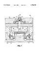
- FIG. 7is an enlarged cross-sectional view of the top central portion of a fourth embodiment of a liquid material dispenser according to the invention.
- FIG. 1illustrates a basic embodiment of a liquid material dispenser according to the present invention designed to deliver drugs at a slow, controlled and precise rate.
- the dispenseris assumed to be used for the dispensing of medication, it being understood that such an application is merely illustrative of the many applications wherein it is desired to intermittently deliver a controlled amount of liquid at a relatively slow rate.
- the present inventionis intended to cover all such applications and is not limited to medicinal applications.
- the illustrated liquid dispenserhas a housing 10 enclosing a reservoir 12 which contains the liquid to be dispensed.
- Housing 10also includes an outlet 14 through which the liquid is dispensed, and a connecting passageway 16 between reservoir 12 and outlet 14.
- Passageway 16includes an enlarged cavity which contains a movable, or reciprocatable, pumping member, preferably a diaphragm 18, which divides the enlarged cavity into a pumping chamber 20 and a pressure control chamber 22.
- Diaphragm 18serves as a reciprocating pumping member and is cyclically displaceable through a pumping stroke and a drawing stroke to effect the movement of liquid from reservoir 12 through outlet 14.
- differential pressure across diaphragm 18causes it to move in one direction (upwards in FIG. 1) as liquid moves from reservoir 12 to pumping chamber 20.
- diaphragm 18is caused to move in the other direction (downwards in FIG. 1) causing liquid to move from pumping chamber 20 through passageway 16 to outlet 14.
- the motion of diaphragm 18 during the pumping strokeis preferably brought about by an electrolytic cell 24 having a suitable electrolyte, such as sodium bicarbonate or, preferably, potassium acetate, located within housing 10 and in communication with pressure control chamber 22 via a bore 26. Also shown in FIG. 1 is a pair of electrodes 28 which are connected to a suitable electrical energy source (not shown) which may be housed either within or outside housing 10.
- a suitable electrolytesuch as sodium bicarbonate or, preferably, potassium acetate
- Electrolytic cell 24may be of any known construction. Examples of possible configuration are described in U.S. Pat. Nos. 5,062,834 and 5,090,963, and in our International Patent Publication WO 93/23096.
- electrolytic cell 24Whenever appropriate, electrical energy is supplied to electrodes 28 at a preselected rate, bringing about electrolytic reactions which produce gases.
- the rate of gas productionis related to the electrical current supplied to electrolytic cell 24 and the total amount of gases produced is related to the total electrical energy supplied to the cell.
- the produced gasesflow from electrolytic cell 24 to pressure control chamber 22 through bore 26 to displace diaphragm 18 and thereby effect the pumping of liquid from pumping chamber 20 through the downstream portion of passageway 16 and out through outlet 14.
- a downstream one-way valve 30is anchored in that portion of passageway 16 between pumping chamber 20 and outlet 14 and is oriented such that during the pumping stroke of diaphragm 18, liquid is moved from pumping chamber 20 through outlet 14.
- An upstream one-way valve 32is anchored in that portion of passageway 16 between reservoir 12 and pumping chamber 20 and is oriented such that during the drawing stroke of diaphragm 18, liquid is drawn from reservoir 12 into pumping chamber 20.
- One-way valves 30 and 32can be of any suitable design, including the design described in our International Patent Publication WO 93/23096.
- one-way valvesare of the unique design described below. It is to be noted that while the one-way valve described below is suitable for use in the context of a liquid material dispenser according to the present invention, it will be readily apparent to the reader that such valves may also be used in various other applications. It is intended that all such applications fall within the scope of the present invention.
- Each of one-way valves 30 and 32 according to the present inventionincludes means for fixing the position of the valve relative to the passageway, for example, a rim 34 which is suitably connected to housing 10 (FIG. 1).
- a flexible member 36Connected to rim 34, preferably integrally formed with it, is a flexible member 36, preferably made of a suitable plastics or rubber.
- Flexible memberhas a convex side which is installed so as to face in the desired direction of the flow and a concave side which faces the opposite direction.
- flexible member 36is hemispherical, or partly spherical, in shape.
- Flexible member 36features near its centre a slit 38 of suitable length and shape.
- diaphragm 18moves upwards and pressure is reduced in pumping chamber 20, on the concave side of downstream valve 30 and on the convex side of upstream valve 32.
- the reduction in pressureallows liquid to move through the upstream valve 32 and at the same time tightly closes downstream valve 30 to prevent any liquid from entering the device from the outside through outlet 14.
- a liquid material dispenser according to the present inventionfurther features a vent mechanism for venting gases created by electrolytic cell 24 from pressure control chamber 22 to the atmosphere.
- the ventingdrops the pressure in pressure control chamber 22 and causes diaphragm 18 to move so as to draw liquid from reservoir 12 into pumping chamber 20, as described above.
- the vent mechanismincludes an inlet vent opening 40 located in pressure control chamber 22. As will be described below in more detail, inlet vent opening 40 is caused to alternately open to end the pumping stroke and vent pressure control chamber 22 and to close after a portion of the gases has vented.
- the vent mechanismincludes a displaceable member 42 which is connected to diaphragm 18.
- Displaceable member 42is formed with inlet vent opening 40 which is in communication with a flexible vent conduit 44 connected to diaphragm 18 and leading to the atmosphere through a fixed vent conduit 46 formed in housing 10.
- the communication between inlet vent opening 40 and flexible vent conduit 44is preferably effected through a hollow portion of displaceable member 42.
- the vent mechanismfurther includes a blocking member 48 which is slidably mounted over displaceable member 42 so that blocking member 48 can alternately block and uncover inlet vent opening 40 as described in more detail below.
- displaceable member 42includes a section which is frusto-conical in shape and blocking member 48 is annular with an inner diameter which is somewhat bigger than the outside diameter of the smallest diameter portion of the frusto-conical segment of displaceable member 42.
- displaceable member 42features means for preventing blocking member 48 from translating relative to said displaceable member beyond a certain location, such as a ledge 50, adjoining the largest diameter portion of the frusto-conical segment of displaceable member 42, and having an outside diameter which is somewhat larger than the inner diameter of blocking member 48, thereby preventing blocking member from sliding past ledge 50.
- the function of ledge 50can also be achieved by other means, such as the horizontal portion 51 of displaceable member 42 shown in FIG. 3.
- Blocking member 48is normally biased in a direction away from diaphragm 18 (upwards in FIG. 1). Thus, whenever blocking member 48 abuts against ledge 50, displaceable member 42 is also biased in the same direction.
- displaceable member 42The relative location and dimensions of displaceable member 42, blocking member 48 and inlet vent opening 40 are such that whenever blocking member 48 abuts against ledge 50, inlet vent opening 40 is blocked, or closed, thereby preventing gases from leaving pressure control chamber 22.
- biasing of blocking member 48, and therefore of displaceable member 42, as described above,is preferably achieved through use of one or more biasing springs, preferably one or more leaf springs 52, one end of each of which touches, or connects to, a wall of pressure control chamber 22 while the other end touches, or connects to, blocking member 48.
- leaf springs 52fit into recessions in the walls of pressure control chamber 22 and blocking member 48.
- leaf spring 52is such that when the vent mechanism is in its neutral position (shown in FIGS. 1 and 3), leaf spring 52 is slightly bent so as to produce the upward bias on blocking member 48 and displaceable member 42, as described above.
- the venting of the gasesbrings about a rapid pressure drop in pressure control chamber 22 causing the pressure in pressure control chamber 22 to rapidly fall from a pressure above that in pumping chamber 20 to a pressure below the pressure in pumping chamber 20.
- the resulting pressure differentialpushes displaceable member 42 rapidly upward.
- abutting portion 54 of displaceable member 42pushes blocking member 48 upward past the anchoring point of leaf spring 52 in the wall of pressure control chamber 22 which causes leaf spring 52 to bend upwards, thereby upwardly biasing blocking member 48, and displaceable member 42, as described above, and causing blocking member 48 to block, or close, inlet vent opening 40, thereby terminating the venting of gases from pressure control chamber 22.
- leaf spring 52as well as the other components of the vent mechanism, are designed to actuate as described above so that a substantially fixed quantity of liquid is dispensed daring each pumping stroke.
- a dispenser according to the present inventionalso includes a pair of electrical contacts 56 which are arranged so that when displaceable member 42 is in its upwardly biased position contacts 56 are touching each other, while when displaceable member 42 is displaced downward during venting, as described above, contacts 56 are slightly separated from each other, through, for example, a slight downward bias on the lower of the two contacts 56.
- Contacts 56are electrically connected to taps 58 which are, in turn, connected to a suitable electrical circuit (not shown) which senses the moment of separation of contacts 56 and is capable of using the information to cut off electrical energy to electrolytic cell 24 so that no gases are generated while pressure control chamber 22 is vented and during the period from the completion of the venting until the initiation of the next pumping stroke.
- FIG. 3Shown in FIG. 3 is a second embodiment according to the present invention, wherein inlet vent opening 40 does not communicate with a flexible vent conduit as in the embodiment of FIG. 1, but rather communicates directly with a vent conduit 60 which is connected to, or preferably, integrally formed with, displaceable member 42.
- Vent conduit 60is sufficiently long to extend through housing 10 to the atmosphere.
- a suitable seal 62allows vent conduit 60 to slide up and down yet seals pressure control chamber 22 so that no gases can escape except through vent conduit 60.
- FIG. 3can include contacts 56 and taps 58 as shown in the embodiment of FIG. 1. These have been omitted from FIG. 3 to enhance clarity.
- Housing 10, reservoir 12 and/or diaphragm 18may be made of any suitable configuration, e.g., circular or rectangular in cross-section, and may be made of any suitable materials.
- housing 10is made of a plurality of sections--a top section 10a, a middle section 10b and a bottom section 10c. Top section 10a and middle section 10b clamp together to define between them pumping chamber 20 and pressure control chamber 22 and further form a volume which serves to house electrolytic cell 24.
- Middle section 10b and bottom section 10cclamp together to define between them a cavity which includes reservoir 12 and to hold in place a rolling diaphragm 64, which is flexible and preferably made of silicon rubber. It will be seen that reservoir 12 is defined by middle section 10b and rolling diaphragm 64. Rolling diaphragm 64 is shown in FIGS. 1 and 3 as it would appear when reservoir 12 is full of liquid. Shown in broken lines in FIG. 3 is rolling diaphragm 64 as it would appear when reservoir 12 is empty. Diaphragm 18 and a reservoir vent opening 68 permit reservoir 12 to expand and contract according to the amount of liquid material contained in reservoir 12 as rolling membrane 64 moves.
- Middle section 10bcarries an injection plug 66 for filling the reservoir by injection via a syringe needle (not shown).
- Middle section 10balso includes an injection vent 69 which allows air to escape during the injection of liquid into reservoir 12.
- valves 30 and 32are secured in openings formed in middle section 10b.
- the illustrated dispenseroperates as follows. Reservoir 12 is filled with liquid using a syringe (not shown) which pierces injection plug 66. Injection is continued until the injected liquid begins to exit from outlet 14, indicating that reservoir 12, connecting passageway 16 and pumping chamber 20 are all completely filled with the liquid.
- the rate of delivery of the liquid from reservoir 12 to outlet 14is controlled by an electrical control circuit (not shown) which controls the energizing of electrolytic cell 24 through electrodes 28.
- electrolytic cell 24generates a gas or gases which are fed via bore 26 to pressure control chamber 22. These gases displace diaphragm 18 downward, thereby stressing diaphragm 18 and contracting pumping chamber 20.
- This contraction of pumping chamber 20applies a pressure via passageway 16 to close upstream valve 32 and open downstream valve 30. Accordingly, liquid from pumping chamber 20 is pumped via valve 30 through outlet 14 while electrolytic cell 24 produces gas at a rate which is related to the magnitude of electrical current supplied to it.
- blocking member 48moves downward relative to displaceable member 42 exposing inlet vent opening 40 and venting pressure control chamber 22, and simultaneously interrupting the generation of gases by electrolytic cell 24.
- blocking member 48 and displaceable member 42, as well as the other components of the vent mechanismreturn to their rest position (as shown in FIGS. 1 and 3) with pumping chamber 20 having been refilled with liquid drawn from reservoir 12.
- diaphragm 18When electrical current is again applied to electrolytic cell 24 diaphragm 18 will again be driven through a pumping stroke and will pump the liquid through valve 30 and out through outlet 14.
- FIGS. 4-6Shown in FIGS. 4-6 is a third embodiment according to the present invention, which is generally the same as the embodiments depicted in FIGS. 1 and 3 except for variations in the mechanism used to vent pressure control chamber 22 which are described below.
- a liquid material dispenser according to the embodiment shown in FIGS. 4-6features a somewhat different vent mechanism for venting gases created by electrolytic cell 24 from pressure control chamber 22 to the atmosphere.
- the ventingdrops the pressure in pressure control chamber 22 and causes diaphragm 18 to move so as to draw liquid from reservoir 12 into pumping chamber 20, as described above.
- the vent mechanism shown in FIG. 4, and in more detail, in the enlarged views of FIGS. 5 and 6,includes a displaceable member 142 which is connected to diaphragm 18 and which is made up of a number of portions.
- Displaceable member 142includes an upper member 202 which is able to lie flat against the top inner wall of pressure control chamber 22 when the pressure control chamber is not being vented. Upper member 202 is rigidly connected to the rest of displaceable member 142 via a suitable connecting member 204, which is preferably in the form of a series of ribs extending downward from upper member 202 to a central member 206.
- leaf spring 52Extending through or between connecting member 204, through a slot (not shown) is leaf spring 52 which also passes through an impact member 207 which is not connected to displaceable member 142 and is free to move between upper member 202 and central member 206 of displaceable member 142.
- Leaf spring 52 and impact member 207are located such that the downward motion of upper member 202 causes the downward motion of impact member 207 which in turn, causes the same downward motion of leaf spring 52.
- Central member 206is connected to a lower member 208 and together with it forms a secondary chamber.
- the secondary chamberis split into an upper secondary chamber 210 and a lower secondary chamber 212 by a displaceable plug 214 which is anchored to, or forms a portion of lower member 208.
- Displaceable plug 214features one or more suitably located bores 215 which serve to continuously connect upper secondary chamber 210 and lower secondary chamber 212.
- the size, shape and movement of displaceable plug 214are designed so that it can alternately extend through an opening 216 in central member 206 so as to close off or isolate upper secondary chamber 210, and therefore also lower secondary chamber 212 from pressure control chamber 22, or retreat downward from opening 216 so as to put secondary chamber 210, and therefore also lower secondary chamber 212, in communication with pressure control chamber 22.
- Lower secondary chamber 212is in continuous communication with flexible vent conduit 44 connected to diaphragm 18 and leading to the atmosphere through a fixed vent conduit 46 formed in housing 10.
- leaf spring 52is such that when the vent mechanism is in its neutral position (shown in FIG. 5), leaf spring 52 is slightly bent so as to produce the upward bias on impact member 207.
- displaceable member 142In operation, electrical energy is supplied at a suitable rate to electrolytic cell 24 causing it to generate gases which enter pressure control chamber 22 and raise its pressure. The increased pressure causes diaphragm 18 to move downward so as to push liquid through outlet 14 as described above. Since displaceable member 142 is connected to diaphragm 18, force is exerted on displaceable member 142, moving it downward. The downward movement of displaceable member 142 also serves to move impact member 207 and leaf spring 52 downward.
- leaf spring 52As the downward movement continues, downward force on leaf spring 52 is increased. Eventually the downward force on leaf spring 52 exceeds its upwardly directed biasing force. At this point, leaf spring 52 instantaneously straightens and then bends rapidly in the downward direction, causing impact member 207 to move rapidly downward and impact displaceable plug 214. The impact causes displaceable plug 214 to move downward, which opens the previously closed opening 216, putting pressure control chamber 22 in communication with upper secondary chamber 210 (and therefore with lower secondary chamber 212 and flexible vent conduit 44 and fixed vent conduit 46) and allowing the gases in pressure control chamber 22 to be released outside the device. Since the pressure in pressure control chamber 22 is higher than in the atmosphere outside the dispenser, gases quickly escape to the outside of the dispenser.
- FIG. 7Shown in FIG. 7 is a fourth and presently preferred embodiment according to the present invention, which is generally the same as the embodiments depicted in FIGS. 1, 3 and 4-6 except for variations in the mechanism used to vent pressure control chamber 22, as described below. Accordingly, FIG. 7 shows an enlarged detail of the venting mechanism.
- FIG. 7there is illustrated, generally at 300, a detail of a liquid material dispenser according to the present invention.
- the dispenserhas a housing 310 including a reservoir (not shown) which contains the liquid to be dispensed and including an outlet (not shown) through which the liquid is dispensed.
- the liquidtravels from the reservoir to the outlet via a passageway 312 having an upstream one-way valve and a downstream one-way valve (not shown).
- a passageway 312having an upstream one-way valve and a downstream one-way valve (not shown).
- passageway 312there is located a diaphragm 316 defining on one side thereof, with passageway 312, a pumping chamber 318 and, on the other side thereof, a pressure control chamber 320.
- the diaphragm 316is cyclically displaceable so as to draw liquid into the pumping chamber 318 from the reservoir and upstream valve and to pump liquid from pumping chamber 318 along connecting passageway 312 towards the downstream valve and the outlet in the direction indicated at 322.
- Diaphragm 316is connected via a connecting rod 324 to a vent mechanism, indicated generally at 326, having an inlet vent opening 328.
- a leaf spring 330is secured within pressure control chamber 320 and is connected to connecting rod 324. When the vent mechanism is in its neutral position, leaf spring 330 is slightly bent so as to produce an upward bias on connecting rod 324.
- Inlet vent opening 328is defined between a seal member 332 and housing 310. Seal member 332 is connected via connecting rod 324 to diaphragm 316.
- Pressure control chamber 320extends front diaphragm 316 up to inlet vent opening 328.
- One or more gaps 334 in seal member 332allow communication between lower part 336 and upper part 338 of pressure control chamber 320.
- gasis generated within pressure control chamber 320 by an electrolytic cell 340, causing diaphragm 316 to be displaced downwards through the pumping stroke.
- Leaf spring 330initially opposes this downward force but, as in the other embodiments, the upward bias provided by spring 330 is eventually overcome, and the spring straightens and then snaps downwards when it reaches the horizontal position.
- This snapping actioncauses seal member 332 to snap downwards, causing inlet vent opening 328 to open and thereby allowing the pressurised gas within pressure control chamber 320 to escape via inlet vent opening 328 through a vent outlet 342.
- Seal member 332comprises a central portion 344, a frusto-conical section 346 within which gap 334 is located, and an anchor section 348 holding the seal member 332 in position.
- Hinges 350allow central portion 344 to move downwards and upwards in relation to anchor section 348, which movements respectively open and seal inlet vent opening 328 inside the upper part 338 of pressure control chamber 320.
- the illustrated dispenserdoes not hold large volumes of gases over extended periods, and therefore is not significantly sensitive to temperature and pressure fluctuations.
- a dispenser according to the present inventiontends to deliver substantially the same amount of liquid in each successive pumping stroke.
- the illustrated dispensermay therefore be used for intermittently dispensing precisely set amounts of liquids at precisely controlled rates.
Landscapes
- Health & Medical Sciences (AREA)
- Animal Behavior & Ethology (AREA)
- Veterinary Medicine (AREA)
- Anesthesiology (AREA)
- Biomedical Technology (AREA)
- Heart & Thoracic Surgery (AREA)
- Hematology (AREA)
- Life Sciences & Earth Sciences (AREA)
- Vascular Medicine (AREA)
- Engineering & Computer Science (AREA)
- General Health & Medical Sciences (AREA)
- Public Health (AREA)
- Reciprocating Pumps (AREA)
- Closures For Containers (AREA)
- Feeding, Discharge, Calcimining, Fusing, And Gas-Generation Devices (AREA)
- Devices For Dispensing Beverages (AREA)
- Enzymes And Modification Thereof (AREA)
- Micro-Organisms Or Cultivation Processes Thereof (AREA)
- Coating Apparatus (AREA)
Abstract
Description
The present invention relates to liquid material dispensers, and a valve particularly suitable for use in such dispensers, and more particularly to dispensers for dispensing medicaments at small, precisely controlled rates.
The invention is especially useful where the liquid is driven from the dispenser by the force of gas generated at a suitable rate by an electrolytic cell. Examples of such systems are described in U.S. Pat. Nos. 5,062,834 and 5,090,963, and in our International Patent Publication WO 93/23096, which are incorporated by reference in their entirety for all purposes as if fully set forth herein.
In a variety of applications, including, but not limited to, drug delivery systems, it is required to dispense or deliver a liquid at a predetermined, precisely controlled rate. Electrolytic pumps, such as those described in the above-mentioned U.S. Patents, have been developed for this purpose. These pumps, however, generally include relatively large pumping chambers, and hence their pumping rates may be significantly influenced by pressure and temperature changes, particularly when the dispenser is used over long periods of time and/or under varying ambient conditions.
The electrolytic pump described in our International Patent Publication WO 93/23096 provides a liquid material dispenser or pump of a construction which can include a pumping chamber of relatively small volume so that the rate of delivery of the liquid is less sensitive to pressure and temperature variations.
However, the venting of the pressure control chamber is carried out through a slow acting vent which releases the gas from the pressure control chamber to the atmosphere to thereby drive the pumping member through the return stroke and draw liquid from the reservoir into the pumping chamber. Such a slow vent may at times become plugged, reducing the venting rate or interrupting it entirely. In addition, since the venting is carried out continuously at all times, it tends to reduce the efficiency of the pumping stroke by robbing the pumping chamber of some of its relatively high pressure gases when it is desired that those gases exert maximum force on the diaphragm to pump the liquid.
In addition, the device disclosed in our International Patent Publication WO 93/23096 uses a pair of one-way umbrella valves for controlling the flow of liquid from the reservoir to the outside of the device.
Furthermore, the device described in our International Patent Publication WO 93/23096 is designed so that gas production continues for a pre-determined period of time. The duration is selected so as to deliver the desired amount of liquid through the outlet. However, for a variety of reasons, including, but not limited to, partial plugging of the outlet or temperature and pressure variations, the amount of liquid delivered during a fixed period of time may vary.
There is thus a widely recognized need for, and it would be highly advantageous to have, an electrolytic pump along the lines described in our International Patent Publication WO 93/23096 but which would feature means for more efficiently venting the pressure control chamber and which would make use of more one-way valves, and which would have the ability to automatically discontinue the delivery of liquid when a fixed amount of liquid has been made to pass through the outlet.
According to the present invention there is provided a liquid material dispenser, comprising: (a) a housing including a reservoir for storing liquid to be dispensed, an outlet through which the liquid is dispensed, and a connecting passageway between said reservoir and said outlet; (b) a reciprocatable pumping member located in said passageway, one side of said pumping member defining a pumping chamber with said passageway, and the other side of said pumping member defining a pressure control chamber, said pumping member being cyclically displaceable through a pumping stroke for pumping liquid through said outlet and a drawing stroke for drawing liquid from said reservoir; (c) valve means in said passageway effective, during said drawing stroke, to cause the pumping member to draw liquid from said reservoir into said pumping chamber, and during said pumping stroke, to cause the pumping member to pump liquid from said pumping chamber through said outlet; (d) feeding means for feeding a gas at a preselected time and rate to said pressure control chamber to drive the pumping member through said pumping stroke; and (e) a vent mechanism for venting said gas from said pressure control chamber to the atmosphere to drive the pumping member through said drawing stroke, said vent mechanism having an inlet vent opening inside said pressure control chamber, said opening being caused to open to end said pumping stroke and to close after a portion of said gas has vented.
According to further features in preferred embodiments of the invention described below, the pumping member is a diaphragm and the vent mechanism includes a displaceable member connected to the pumping member, the displaceable member being formed with the inlet vent opening, the inlet vent opening being in communication with a vent conduit leading to the atmosphere, and further includes a blocking member slidably mounted over the displaceable member so that the blocking member can alternately block and uncover the inlet vent opening. The blocking member is biased in a direction away from the pumping member and the displaceable member includes means for preventing the blocking member from translating relative to the displaceable member beyond a certain location, thereby biasing the displaceable member, so that when the blocking member is at said location it blocks the inlet vent opening.
According to still further features in the described preferred embodiments, the biasing of the blocking member is achieved using at least one leaf spring connecting the walls of the pressure control chamber and the blocking member, one end of the leaf spring is held in a recession in the walls of the pressure control chamber and the other end of the leaf spring is held in a recession in the blocking member.
According to one embodiment of the present invention the vent conduit is connected to the pumping member.
According to another embodiment of the present invention the vent conduit is formed with the displaceable member and is slidable through a seal to the atmosphere.
According to further features in preferred embodiments, the feeding means includes an electrolytic cell which includes electrodes and electrolyte and which generates a gas at a rate substantially proportional to the electrical current passing through the electrolyte.
According to yet further features, the valve means comprises: (a) an upstream one-way valve in the passageway located between the reservoir and the pumping chamber and oriented such that during the drawing stroke the pumping member draws liquid from the reservoir to the pumping chamber; and (b) a downstream one-way valve in the passageway located between the pumping chamber and the outlet and oriented such that during the pumping stroke the pumping member pumps liquid from the pumping chamber through the outlet.
Also according to the present invention there is provided a one-way valve for controlling the flow of fluid through a passage, comprising: (a) means for fixing the position of the valve relative to the passageway; (b) a flexible member having a convex side in the direction of the flow and a concave side in the opposite direction; and (c) a slit in the flexible member such that when pressure is exerted upon the concave side the slit is made to open to allow the flow of fluid while when pressure is exerted on the convex side the slit is made to close and prevent the flow of fluid.
The present invention successfully addresses the shortcomings of the presently known configurations by providing a liquid dispenser which is actuated by closing an electrical circuit which activates an electrolytic cell so as to cause gas to be generated at a predetermined rate. When the pumping member has been sufficiently displaced, indicating the delivery through the device outlet of a substantially fixed amount of liquid, the vent opens automatically and, preferably, the gas generation is interrupted. The venting of the pressure control chamber brings about the drawing of additional liquid from the reservoir into the pumping chamber (the drawing stroke), where the liquid remains until gas is again generated so as to drive the diaphragm and thereby pump an additional aliquot of liquid out of the unit, during the pumping stroke.
The principles and operation of a liquid material dispenser and one-way valve according to the present invention may be better understood with reference to the drawings and the accompanying description.
The invention is herein described, by way of example only, with reference to the accompanying drawings, wherein:
FIG. 1 is a cross-sectional view of one embodiment of a liquid material dispenser according to the present invention;
FIG. 2 is a one-way valve according to the present invention;
FIG. 3 is a cross-sectional view of a second embodiment of a liquid material dispenser according to the present invention;
FIG. 4 is a cross-sectional view of a third embodiment of a liquid material dispenser according to the present invention;
FIG. 5 is an enlarged view of the top central portion of the dispenser of FIG. 4 with the leaf spring in its top position;
FIG. 6 is an enlarged view of the toll central portion of the dispenser of FIG. 4 with the leaf spring in its bottom position; and
FIG. 7 is an enlarged cross-sectional view of the top central portion of a fourth embodiment of a liquid material dispenser according to the invention.
Referring now to the drawings, FIG. 1 illustrates a basic embodiment of a liquid material dispenser according to the present invention designed to deliver drugs at a slow, controlled and precise rate. Throughout the discussion which follows the dispenser is assumed to be used for the dispensing of medication, it being understood that such an application is merely illustrative of the many applications wherein it is desired to intermittently deliver a controlled amount of liquid at a relatively slow rate. The present invention is intended to cover all such applications and is not limited to medicinal applications.
The illustrated liquid dispenser according to the present invention has ahousing 10 enclosing areservoir 12 which contains the liquid to be dispensed.Housing 10 also includes anoutlet 14 through which the liquid is dispensed, and a connectingpassageway 16 betweenreservoir 12 andoutlet 14. Passageway 16 includes an enlarged cavity which contains a movable, or reciprocatable, pumping member, preferably adiaphragm 18, which divides the enlarged cavity into apumping chamber 20 and apressure control chamber 22.
The motion ofdiaphragm 18 during the pumping stroke is preferably brought about by anelectrolytic cell 24 having a suitable electrolyte, such as sodium bicarbonate or, preferably, potassium acetate, located withinhousing 10 and in communication withpressure control chamber 22 via abore 26. Also shown in FIG. 1 is a pair ofelectrodes 28 which are connected to a suitable electrical energy source (not shown) which may be housed either within oroutside housing 10.
Whenever appropriate, electrical energy is supplied toelectrodes 28 at a preselected rate, bringing about electrolytic reactions which produce gases. The rate of gas production is related to the electrical current supplied toelectrolytic cell 24 and the total amount of gases produced is related to the total electrical energy supplied to the cell. The produced gases flow fromelectrolytic cell 24 topressure control chamber 22 throughbore 26 to displacediaphragm 18 and thereby effect the pumping of liquid frompumping chamber 20 through the downstream portion ofpassageway 16 and out throughoutlet 14.
A downstream one-way valve 30 is anchored in that portion ofpassageway 16 betweenpumping chamber 20 andoutlet 14 and is oriented such that during the pumping stroke ofdiaphragm 18, liquid is moved frompumping chamber 20 throughoutlet 14.
An upstream one-way valve 32 is anchored in that portion ofpassageway 16 betweenreservoir 12 andpumping chamber 20 and is oriented such that during the drawing stroke ofdiaphragm 18, liquid is drawn fromreservoir 12 intopumping chamber 20.
One-way valves
Preferably, as can best be seen in FIG. 2, one-way valves are of the unique design described below. It is to be noted that while the one-way valve described below is suitable for use in the context of a liquid material dispenser according to the present invention, it will be readily apparent to the reader that such valves may also be used in various other applications. It is intended that all such applications fall within the scope of the present invention.
Each of one-way valves rim 34 which is suitably connected to housing 10 (FIG. 1).
Connected torim 34, preferably integrally formed with it, is aflexible member 36, preferably made of a suitable plastics or rubber. Flexible member has a convex side which is installed so as to face in the desired direction of the flow and a concave side which faces the opposite direction. Preferably,flexible member 36 is hemispherical, or partly spherical, in shape.Flexible member 36 features near its centre aslit 38 of suitable length and shape.
Thus, when diaphragm 18 pushes downward, pressure is exerted on the concave side ofdownstream valve 30 and on the convex side ofupstream valve 32. The exertion of pressure on the concave side ofdownstream valve 30 tends to bendflexible member 36 ofvalve 30 downstream in the direction ofoutlet 14. The bending tends to cause the portions offlexible member 36 ofvalve 30 which border on slit 38 to separate, thereby allowing liquid to flow downstream through the formed opening.
At the same time, the exertion of pressure on the convex side ofupstream valve 32 tends to pushflexible member 36 ofvalve 32 upstream in the direction ofreservoir 12. This tends to cause the portions offlexible member 36 ofvalve 32 which border on slit 38 to come together, thereby sealing the opening and preventing liquid from flowing upstream throughvalve 32.
Similarly, when the pressure inpressure control chamber 22 is reduced, as will be described below,diaphragm 18 moves upwards and pressure is reduced in pumpingchamber 20, on the concave side ofdownstream valve 30 and on the convex side ofupstream valve 32. The reduction in pressure allows liquid to move through theupstream valve 32 and at the same time tightly closesdownstream valve 30 to prevent any liquid from entering the device from the outside throughoutlet 14.
A liquid material dispenser according to the present invention further features a vent mechanism for venting gases created byelectrolytic cell 24 frompressure control chamber 22 to the atmosphere. The venting drops the pressure inpressure control chamber 22 and causesdiaphragm 18 to move so as to draw liquid fromreservoir 12 into pumpingchamber 20, as described above.
The vent mechanism includes an inlet vent opening 40 located inpressure control chamber 22. As will be described below in more detail, inlet vent opening 40 is caused to alternately open to end the pumping stroke and ventpressure control chamber 22 and to close after a portion of the gases has vented.
The vent mechanism includes adisplaceable member 42 which is connected todiaphragm 18.Displaceable member 42 is formed with inlet vent opening 40 which is in communication with aflexible vent conduit 44 connected to diaphragm 18 and leading to the atmosphere through a fixedvent conduit 46 formed inhousing 10. The communication between inlet vent opening 40 andflexible vent conduit 44 is preferably effected through a hollow portion ofdisplaceable member 42.
The vent mechanism further includes a blockingmember 48 which is slidably mounted overdisplaceable member 42 so that blockingmember 48 can alternately block and uncover inlet vent opening 40 as described in more detail below.
Preferably,displaceable member 42 includes a section which is frusto-conical in shape and blockingmember 48 is annular with an inner diameter which is somewhat bigger than the outside diameter of the smallest diameter portion of the frusto-conical segment ofdisplaceable member 42. Preferably also,displaceable member 42 features means for preventing blockingmember 48 from translating relative to said displaceable member beyond a certain location, such as aledge 50, adjoining the largest diameter portion of the frusto-conical segment ofdisplaceable member 42, and having an outside diameter which is somewhat larger than the inner diameter of blockingmember 48, thereby preventing blocking member from slidingpast ledge 50. The function ofledge 50 can also be achieved by other means, such as thehorizontal portion 51 ofdisplaceable member 42 shown in FIG. 3.
Blockingmember 48 is normally biased in a direction away from diaphragm 18 (upwards in FIG. 1). Thus, whenever blockingmember 48 abuts againstledge 50,displaceable member 42 is also biased in the same direction.
The relative location and dimensions ofdisplaceable member 42, blockingmember 48 and inlet vent opening 40 are such that whenever blockingmember 48 abuts againstledge 50, inlet vent opening 40 is blocked, or closed, thereby preventing gases from leavingpressure control chamber 22.
The biasing of blockingmember 48, and therefore ofdisplaceable member 42, as described above, is preferably achieved through use of one or more biasing springs, preferably one ormore leaf springs 52, one end of each of which touches, or connects to, a wall ofpressure control chamber 22 while the other end touches, or connects to, blockingmember 48.
Preferably, the ends ofleaf springs 52 fit into recessions in the walls ofpressure control chamber 22 and blockingmember 48.
The length ofleaf spring 52 is such that when the vent mechanism is in its neutral position (shown in FIGS. 1 and 3),leaf spring 52 is slightly bent so as to produce the upward bias on blockingmember 48 anddisplaceable member 42, as described above.
In operation, electrical energy is supplied at a suitable rate toelectrolytic cell 24 causing it to generate gases which enterpressure control chamber 22 and raise its pressure. The increased pressure causesdiaphragm 18 to move downward so as to push liquid throughoutlet 14 as described above. Sincedisplaceable member 42 is connected to diaphragm 18, a force is exerted ondisplaceable member 42 to move downward. This force is at first counteracted by the upward biasing force exerted byleaf spring 52.
As the downward movement ofdiaphragm 18 continues, the downward force ondisplaceable member 42 increases, eventually equalling and overcoming the biasing force. At this point,leaf springs 52 instantaneously straighten and then bend rapidly in the downward direction, causing blockingmember 48 to slide downward relative todisplaceable member 42, so that blocking member abuts against abuttingportion 54 ofdisplaceable member 42. The relative movement of blockingmember 48 anddisplaceable member 42 exposesinlet vent opening 40. Since the pressure inpressure control chamber 22 is larger than in the atmosphere outside the dispenser, gases flow quickly through inlet vent opening 40,flexible vent conduit 44 and fixedvent conduit 46 and escape to the outside of the dispenser.
The venting of the gases brings about a rapid pressure drop inpressure control chamber 22 causing the pressure inpressure control chamber 22 to rapidly fall from a pressure above that in pumpingchamber 20 to a pressure below the pressure in pumpingchamber 20. The resulting pressure differential pushesdisplaceable member 42 rapidly upward. Asdisplaceable member 42 moves upward, abuttingportion 54 ofdisplaceable member 42pushes blocking member 48 upward past the anchoring point ofleaf spring 52 in the wall ofpressure control chamber 22 which causesleaf spring 52 to bend upwards, thereby upwardly biasing blockingmember 48, anddisplaceable member 42, as described above, and causing blockingmember 48 to block, or close, inlet vent opening 40, thereby terminating the venting of gases frompressure control chamber 22.
The length and strength ofleaf spring 52, as well as the other components of the vent mechanism, are designed to actuate as described above so that a substantially fixed quantity of liquid is dispensed daring each pumping stroke.
Preferably, a dispenser according to the present invention also includes a pair ofelectrical contacts 56 which are arranged so that whendisplaceable member 42 is in its upwardlybiased position contacts 56 are touching each other, while whendisplaceable member 42 is displaced downward during venting, as described above,contacts 56 are slightly separated from each other, through, for example, a slight downward bias on the lower of the twocontacts 56.
Shown in FIG. 3 is a second embodiment according to the present invention, wherein inlet vent opening 40 does not communicate with a flexible vent conduit as in the embodiment of FIG. 1, but rather communicates directly with avent conduit 60 which is connected to, or preferably, integrally formed with,displaceable member 42. Ventconduit 60 is sufficiently long to extend throughhousing 10 to the atmosphere. Asuitable seal 62 allows ventconduit 60 to slide up and down yet sealspressure control chamber 22 so that no gases can escape except throughvent conduit 60.
As will be readily apparent to the reader, the embodiment shown in FIG. 3 can includecontacts 56 and taps 58 as shown in the embodiment of FIG. 1. These have been omitted from FIG. 3 to enhance clarity.
For ease in assembly and disassembly of the illustrated dispenser,housing 10 is made of a plurality of sections--atop section 10a, amiddle section 10b and abottom section 10c.Top section 10a andmiddle section 10b clamp together to define between them pumpingchamber 20 andpressure control chamber 22 and further form a volume which serves to houseelectrolytic cell 24.
Therims 34 ofvalves middle section 10b.
The illustrated dispenser operates as follows.Reservoir 12 is filled with liquid using a syringe (not shown) which piercesinjection plug 66. Injection is continued until the injected liquid begins to exit fromoutlet 14, indicating thatreservoir 12, connectingpassageway 16 and pumpingchamber 20 are all completely filled with the liquid.
The rate of delivery of the liquid fromreservoir 12 tooutlet 14 is controlled by an electrical control circuit (not shown) which controls the energizing ofelectrolytic cell 24 throughelectrodes 28. During the interval whenelectrodes 28 are energized,electrolytic cell 24 generates a gas or gases which are fed viabore 26 to pressurecontrol chamber 22. These gases displacediaphragm 18 downward, thereby stressingdiaphragm 18 andcontracting pumping chamber 20. This contraction of pumpingchamber 20 applies a pressure viapassageway 16 to closeupstream valve 32 and opendownstream valve 30. Accordingly, liquid from pumpingchamber 20 is pumped viavalve 30 throughoutlet 14 whileelectrolytic cell 24 produces gas at a rate which is related to the magnitude of electrical current supplied to it.
As described above, at a certain point in the pumping stroke, blockingmember 48 moves downward relative todisplaceable member 42 exposing inlet vent opening 40 and ventingpressure control chamber 22, and simultaneously interrupting the generation of gases byelectrolytic cell 24.
Following venting, blockingmember 48 anddisplaceable member 42, as well as the other components of the vent mechanism, return to their rest position (as shown in FIGS. 1 and 3) with pumpingchamber 20 having been refilled with liquid drawn fromreservoir 12.
When electrical current is again applied toelectrolytic cell 24diaphragm 18 will again be driven through a pumping stroke and will pump the liquid throughvalve 30 and out throughoutlet 14.
Shown in FIGS. 4-6 is a third embodiment according to the present invention, which is generally the same as the embodiments depicted in FIGS. 1 and 3 except for variations in the mechanism used to ventpressure control chamber 22 which are described below.
A liquid material dispenser according to the embodiment shown in FIGS. 4-6 features a somewhat different vent mechanism for venting gases created byelectrolytic cell 24 frompressure control chamber 22 to the atmosphere. The venting drops the pressure inpressure control chamber 22 and causesdiaphragm 18 to move so as to draw liquid fromreservoir 12 into pumpingchamber 20, as described above.
The vent mechanism shown in FIG. 4, and in more detail, in the enlarged views of FIGS. 5 and 6, includes adisplaceable member 142 which is connected to diaphragm 18 and which is made up of a number of portions.
Extending through or between connectingmember 204, through a slot (not shown) isleaf spring 52 which also passes through animpact member 207 which is not connected todisplaceable member 142 and is free to move betweenupper member 202 andcentral member 206 ofdisplaceable member 142.Leaf spring 52 andimpact member 207 are located such that the downward motion ofupper member 202 causes the downward motion ofimpact member 207 which in turn, causes the same downward motion ofleaf spring 52.
Lowersecondary chamber 212 is in continuous communication withflexible vent conduit 44 connected to diaphragm 18 and leading to the atmosphere through a fixedvent conduit 46 formed inhousing 10.
The length ofleaf spring 52 is such that when the vent mechanism is in its neutral position (shown in FIG. 5),leaf spring 52 is slightly bent so as to produce the upward bias onimpact member 207.
In operation, electrical energy is supplied at a suitable rate toelectrolytic cell 24 causing it to generate gases which enterpressure control chamber 22 and raise its pressure. The increased pressure causesdiaphragm 18 to move downward so as to push liquid throughoutlet 14 as described above. Sincedisplaceable member 142 is connected to diaphragm 18, force is exerted ondisplaceable member 142, moving it downward. The downward movement ofdisplaceable member 142 also serves to moveimpact member 207 andleaf spring 52 downward.
As the downward movement continues, downward force onleaf spring 52 is increased. Eventually the downward force onleaf spring 52 exceeds its upwardly directed biasing force. At this point,leaf spring 52 instantaneously straightens and then bends rapidly in the downward direction, causingimpact member 207 to move rapidly downward and impactdisplaceable plug 214. The impact causesdisplaceable plug 214 to move downward, which opens the previously closedopening 216, puttingpressure control chamber 22 in communication with upper secondary chamber 210 (and therefore with lowersecondary chamber 212 andflexible vent conduit 44 and fixed vent conduit 46) and allowing the gases inpressure control chamber 22 to be released outside the device. Since the pressure inpressure control chamber 22 is higher than in the atmosphere outside the dispenser, gases quickly escape to the outside of the dispenser.
The venting of the gases brings about a rapid pressure drop inpressure control chamber 22 causing the pressure inpressure control chamber 22 to rapidly fall from a pressure above that in pumpingchamber 20 to a pressure below the pressure in pumpingchamber 20. The resulting pressure differential pushesdisplaceable member 142 rapidly upward. Asdisplaceable member 142 moves upwards eventuallyleaf spring 52 bends upward to pushimpact member 207 upward and away fromdisplaceable plug 214, allowingdisplaceable plug 214 to rise so as to once againclose opening 216 betweenpressure control chamber 22 and the outside of the dispenser.
Shown in FIG. 7 is a fourth and presently preferred embodiment according to the present invention, which is generally the same as the embodiments depicted in FIGS. 1, 3 and 4-6 except for variations in the mechanism used to ventpressure control chamber 22, as described below. Accordingly, FIG. 7 shows an enlarged detail of the venting mechanism.
Thus, in FIG. 7 there is illustrated, generally at 300, a detail of a liquid material dispenser according to the present invention. The dispenser has ahousing 310 including a reservoir (not shown) which contains the liquid to be dispensed and including an outlet (not shown) through which the liquid is dispensed. As with the embodiments illustrated in FIGS. 1, 3 and 4-6, the liquid travels from the reservoir to the outlet via apassageway 312 having an upstream one-way valve and a downstream one-way valve (not shown). Thus, liquid coming from the reservoir and upstream valve throughpassageway 312 enters the illustrated portion of the dispenser via the part ofpassageway 312 indicated at 314 in FIG. 7. Withinpassageway 312 there is located adiaphragm 316 defining on one side thereof, withpassageway 312, apumping chamber 318 and, on the other side thereof, apressure control chamber 320. Thediaphragm 316 is cyclically displaceable so as to draw liquid into thepumping chamber 318 from the reservoir and upstream valve and to pump liquid from pumpingchamber 318 along connectingpassageway 312 towards the downstream valve and the outlet in the direction indicated at 322.
In operation, gas is generated withinpressure control chamber 320 by anelectrolytic cell 340, causingdiaphragm 316 to be displaced downwards through the pumping stroke.Leaf spring 330 initially opposes this downward force but, as in the other embodiments, the upward bias provided byspring 330 is eventually overcome, and the spring straightens and then snaps downwards when it reaches the horizontal position. This snapping action causes sealmember 332 to snap downwards, causing inlet vent opening 328 to open and thereby allowing the pressurised gas withinpressure control chamber 320 to escape via inlet vent opening 328 through avent outlet 342.
The escape of the pressurised gas allowsleaf spring 330 to relax, wherebydiaphragm 316, connectingrod 324 andseal member 332 move upwards, until inlet vent opening 328 is resealed. The upward movement ofdiaphragm 316 draws liquid from the reservoir through the upstream valve and via the connecting passageway at 314 into pumpingchamber 318. Thus, pumpingchamber 318 is refilled and inlet vent opening 328 is rescaled allowing the pumping stroke to begin again.
It will be appreciated that the illustrated dispenser does not hold large volumes of gases over extended periods, and therefore is not significantly sensitive to temperature and pressure fluctuations. In addition, it will be noted that a dispenser according to the present invention tends to deliver substantially the same amount of liquid in each successive pumping stroke. The illustrated dispenser may therefore be used for intermittently dispensing precisely set amounts of liquids at precisely controlled rates.
Claims (19)
1. A liquid material dispenser, comprising:
(a) a housing including a reservoir for storing liquid to be dispensed, an outlet through which the liquid is dispensed, and a connecting passageway between said reservoir and said outlet;
(b) a reciprocatable pumping member located in said passageway, one side of said pumping member defining a pumping chamber with said passageway, and the other side of said pumping member defining a pressure control chamber, said pumping member being cyclically displaceable through a pumping stroke for pumping liquid through said outlet and a drawing stroke for drawing liquid from said reservoir;
(c) valve means in said passageway effective, during said drawing stroke, to cause the pumping member to draw liquid from said reservoir into said pumping chamber, and during said pumping stroke, to cause the pumping member to pump liquid from said pumping chamber through said outlet;
(d) feeding means for feeding a gas at a preselected time and rate to said pressure control chamber to drive the pumping member through said pumping stroke; and
(e) a vent mechanism for venting said gas from said pressure control chamber to the atmosphere to drive the pumping member through said drawing stroke, said vent mechanism including: an inlet vent opening providing communication between the pressure control chamber and the atmosphere; said opening being caused to open to end said pumping stroke and to close after a portion of said gas has vented, wherein said vent mechanism includes a displaceable member connected to said pumping member, such that the opening and sealing of the vent opening occurs as a result of the movement of the displaceable member under the action of the pumping member.
2. A dispenser as claimed in claim 1, wherein said displaceable member is formed with said inlet vent opening, and said inlet vent opening is in communication with a vent conduit leading to the atmosphere.
3. A dispenser as claimed in claim 2, wherein said vent mechanism further includes a blocking member slidably mounted over said displaceable member so that said blocking member can alternately block and uncover said inlet vent opening.
4. A dispenser as claimed in claim 3, wherein said blocking member is biased in a direction away from said pumping member and wherein said displaceable member includes means for preventing said blocking member from translating relative to said displaceable member beyond a certain location, thereby biasing said displaceable member, so that when said blocking member is at said location it blocks said inlet vent opening.
5. A dispenser as claimed in claim 4, wherein said means for preventing said blocking member from translating relative to said displaceable member beyond a certain location includes a ledge formed with said displaceable member having a transverse dimension larger than the transverse dimension of the opening of said blocking member.
6. A dispenser as claimed in claim 4, wherein said biasing of said blocking member is achieved using at least one leaf spring connecting the walls of said pressure control chamber and said blocking member.
7. A dispenser as claimed in claim 6, wherein one end of said leaf spring is held in a recession in the walls of said pressure control chamber and the other end of said leaf spring is held in a recession in said blocking member.
8. A dispenser as claimed in claim 2, wherein said vent conduit is connected to said pumping member.
9. A dispenser as claimed in claim 8, further comprising a pair of electrical contacts arranged so that when said displaceable member is in its biased position said contacts make contact with each other.
10. A dispenser as claimed in claim 2, wherein said vent conduit is formed with said displaceable member and is slidable through a seal to the atmosphere.
11. A dispenser as claimed in claim 1, wherein said feeding means includes an electrolytic cell which includes electrodes and electrolyte and which generates a gas at a rate substantially proportional to the electrical current passing through said electrolyte.
12. A dispenser as claimed in claim 11, further comprising a pair of electrical contacts arranged so that when said displaceable member is in its biased position said contacts make contact with each other to close an electrical circuit, which circuit controls said gas generation.
13. A dispenser as claimed in claim 11, wherein said electrolytic cell communicates with said pressure control chamber.
14. A dispenser as claimed in claim 1, wherein said pumping member is a diaphragm.
15. A dispenser as claimed in claim 1, wherein said vent mechanism further comprises a seal member anchored to the housing, said seal member having a portion which is movable relative to the housing to open or seal the vent opening, and said displaceable member being connected both to the pumping member and to said portion of the seal member.
16. A dispenser as claimed in claim 1, wherein said housing includes a top section, a middle section and a bottom section, said pressure control chamber and said pumping chamber being defined by said top and said middle sections.
17. A dispenser as claimed in claim 1, wherein said housing includes a top section, a middle section and a bottom section, said reservoir being defined by said middle and bottom sections, said middle section including an injection plug and said bottom section including a reservoir vent opening.
18. A dispenser as claimed in claim 1, wherein said valve means comprises:
(a) an upstream one-way valve in said passageway located between said reservoir and said pumping chamber and oriented such that during said drawing stroke the pumping member draws liquid from said reservoir to said pumping chamber; and
(b) a downstream one-way valve in said passageway located between said pumping chamber and said outlet and oriented such that during said pumping stroke the pumping member pumps liquid from said pumping chamber through said outlet.
19. A dispenser as claimed in claim 18, wherein said upstream and downstream valves each include means for fixing the position of said valves relative to said passageway and further include a flexible member having a convex side in the direction of the flow and a concave side in the opposite direction, said flexible member having a slit such that when pressure is exerted upon said concave side said slit is made to open to allow the flow of fluid while when pressure is exerted on the convex side said slit is made to close and prevent the flow of fluid.
Applications Claiming Priority (3)
| Application Number | Priority Date | Filing Date | Title |
|---|---|---|---|
| IE930532 | 1993-07-19 | ||
| IE930532AIE930532A1 (en) | 1993-07-19 | 1993-07-19 | Liquid material dispenser and valve |
| PCT/IE1994/000037WO1995003078A1 (en) | 1992-07-13 | 1994-07-15 | Liquid material dispenser and valve |
Publications (1)
| Publication Number | Publication Date |
|---|---|
| US5704520Atrue US5704520A (en) | 1998-01-06 |
Family
ID=11040017
Family Applications (1)
| Application Number | Title | Priority Date | Filing Date |
|---|---|---|---|
| US08/591,583Expired - Fee RelatedUS5704520A (en) | 1993-07-19 | 1994-07-15 | Liquid material dispenser and valve |
Country Status (13)
| Country | Link |
|---|---|
| US (1) | US5704520A (en) |
| EP (1) | EP0708665B1 (en) |
| JP (1) | JPH09505208A (en) |
| KR (1) | KR960703631A (en) |
| AT (1) | ATE195657T1 (en) |
| AU (1) | AU675558B2 (en) |
| CA (1) | CA2167058A1 (en) |
| DE (1) | DE69425660T2 (en) |
| IE (1) | IE930532A1 (en) |
| IL (1) | IL110357A0 (en) |
| NZ (1) | NZ268414A (en) |
| TW (1) | TW250438B (en) |
| ZA (1) | ZA945272B (en) |
Cited By (164)
| Publication number | Priority date | Publication date | Assignee | Title |
|---|---|---|---|---|
| US5957895A (en) | 1998-02-20 | 1999-09-28 | Becton Dickinson And Company | Low-profile automatic injection device with self-emptying reservoir |
| US6152898A (en)* | 1999-04-30 | 2000-11-28 | Medtronic, Inc. | Overfill protection systems for implantable drug delivery devices |
| US6186982B1 (en)* | 1998-05-05 | 2001-02-13 | Elan Corporation, Plc | Subcutaneous drug delivery device with improved filling system |
| NL1013524C2 (en)* | 1999-11-08 | 2001-05-09 | Univ Amsterdam | Machine for organ perfusion during the transport phase of a donor organ. |
| US6256533B1 (en) | 1999-06-09 | 2001-07-03 | The Procter & Gamble Company | Apparatus and method for using an intracutaneous microneedle array |
| US6312612B1 (en) | 1999-06-09 | 2001-11-06 | The Procter & Gamble Company | Apparatus and method for manufacturing an intracutaneous microneedle array |
| US6379324B1 (en) | 1999-06-09 | 2002-04-30 | The Procter & Gamble Company | Intracutaneous microneedle array apparatus |
| WO2002004046A3 (en)* | 2000-07-07 | 2002-06-13 | Fluidsense Corp | Infusion pump cassette |
| US6458102B1 (en)* | 1999-05-28 | 2002-10-01 | Medtronic Minimed, Inc. | External gas powered programmable infusion device |
| US6485461B1 (en) | 2000-04-04 | 2002-11-26 | Insulet, Inc. | Disposable infusion device |
| US20020177858A1 (en)* | 2000-10-16 | 2002-11-28 | Sherman Faiz Feisal | Microstructures and method for treating and conditioning skin which cause less irritation during exfoliation |
| WO2003018089A1 (en)* | 2001-08-31 | 2003-03-06 | Institute Of Materials Research And Engineering | Liquid delivering device |
| US6565532B1 (en) | 2000-07-12 | 2003-05-20 | The Procter & Gamble Company | Microneedle apparatus used for marking skin and for dispensing semi-permanent subcutaneous makeup |
| US6572740B2 (en) | 2000-04-13 | 2003-06-03 | Elan Pharma International Limited | Electrolytic cell |
| US6591124B2 (en) | 2001-05-11 | 2003-07-08 | The Procter & Gamble Company | Portable interstitial fluid monitoring system |
| US6635049B1 (en)* | 1999-04-30 | 2003-10-21 | Medtronic, Inc. | Drug bolus delivery system |
| US20030220656A1 (en)* | 2002-05-24 | 2003-11-27 | Vladimir Gartstein | Method of exfoliation of skin using closely-packed microstructures |
| US6656158B2 (en) | 2002-04-23 | 2003-12-02 | Insulet Corporation | Dispenser for patient infusion device |
| US6656159B2 (en) | 2002-04-23 | 2003-12-02 | Insulet Corporation | Dispenser for patient infusion device |
| US6663820B2 (en) | 2001-03-14 | 2003-12-16 | The Procter & Gamble Company | Method of manufacturing microneedle structures using soft lithography and photolithography |
| US6669669B2 (en) | 2001-10-12 | 2003-12-30 | Insulet Corporation | Laminated patient infusion device |
| US20040001766A1 (en)* | 2002-05-14 | 2004-01-01 | Maianti Edgardo Costa | Unit for pumping fluid, particularly blood |
| US20040015131A1 (en)* | 2002-07-16 | 2004-01-22 | Flaherty J. Christopher | Flow restriction system and method for patient infusion device |
| US20040027083A1 (en)* | 2002-04-26 | 2004-02-12 | Toyoda Koki Kabushiki Kaisha | Motor control device |
| US6692457B2 (en) | 2002-03-01 | 2004-02-17 | Insulet Corporation | Flow condition sensor assembly for patient infusion device |
| US6699218B2 (en) | 2000-11-09 | 2004-03-02 | Insulet Corporation | Transcutaneous delivery means |
| US20040064096A1 (en)* | 2002-09-30 | 2004-04-01 | Flaherty J. Christopher | Components and methods for patient infusion device |
| US20040064088A1 (en)* | 2002-09-30 | 2004-04-01 | William Gorman | Dispenser components and methods for patient infusion device |
| US6723072B2 (en) | 2002-06-06 | 2004-04-20 | Insulet Corporation | Plunger assembly for patient infusion device |
| US20040078028A1 (en)* | 2001-11-09 | 2004-04-22 | Flaherty J. Christopher | Plunger assembly for patient infusion device |
| US20040087992A1 (en)* | 2002-08-09 | 2004-05-06 | Vladimir Gartstein | Microstructures for delivering a composition cutaneously to skin using rotatable structures |
| US20040087894A1 (en)* | 2000-09-08 | 2004-05-06 | Flaherty J. Christopher | Devices, systems and methods for patient infusion |
| US6749587B2 (en) | 2001-02-22 | 2004-06-15 | Insulet Corporation | Modular infusion device and method |
| US20040116866A1 (en)* | 2002-12-17 | 2004-06-17 | William Gorman | Skin attachment apparatus and method for patient infusion device |
| US20040116847A1 (en)* | 2002-09-12 | 2004-06-17 | Children's Hospital Medical Center | Method and device for painless injection of medication |
| US6768425B2 (en) | 2000-12-21 | 2004-07-27 | Insulet Corporation | Medical apparatus remote control and method |
| US20040153032A1 (en)* | 2002-04-23 | 2004-08-05 | Garribotto John T. | Dispenser for patient infusion device |
| US20040164454A1 (en)* | 2003-02-24 | 2004-08-26 | The Procter & Gamble Company | Method for manufacturing microstructures having multiple microelements with through-holes |
| US20040173633A1 (en)* | 1999-05-21 | 2004-09-09 | Matsushita Electric Industrial Co., Ltd. | Viscous material application apparatus |
| US6821281B2 (en) | 2000-10-16 | 2004-11-23 | The Procter & Gamble Company | Microstructures for treating and conditioning skin |
| US6830558B2 (en) | 2002-03-01 | 2004-12-14 | Insulet Corporation | Flow condition sensor assembly for patient infusion device |
| US20050065760A1 (en)* | 2003-09-23 | 2005-03-24 | Robert Murtfeldt | Method for advising patients concerning doses of insulin |
| US20050070847A1 (en)* | 2003-09-29 | 2005-03-31 | Van Erp Wilhelmus Petrus Martinus Maria | Rapid-exchange balloon catheter with hypotube shaft |
| US20050118388A1 (en)* | 1999-11-15 | 2005-06-02 | Velcro Industries B.V., A Netherlands Corporation | Skin attachment member |
| US20050136099A1 (en)* | 2003-12-22 | 2005-06-23 | Unilever Home & Personal Care Usa, Division Of Conopco, Inc. | Exfoliating personal care wipe article |
| US20050171477A1 (en)* | 2002-05-23 | 2005-08-04 | Seedlings Life Science Ventures | Apparatus and method for rapid auto-injection of medication |
| US20050182366A1 (en)* | 2003-04-18 | 2005-08-18 | Insulet Corporation | Method For Visual Output Verification |
| US20050238507A1 (en)* | 2002-04-23 | 2005-10-27 | Insulet Corporation | Fluid delivery device |
| US6960192B1 (en) | 2002-04-23 | 2005-11-01 | Insulet Corporation | Transcutaneous fluid delivery system |
| US20060013716A1 (en)* | 2002-04-22 | 2006-01-19 | Medtronic Minimed, Inc. | Shape memory alloy wire driven positive displacement micropump with pulsatile output |
| US7008403B1 (en) | 2002-07-19 | 2006-03-07 | Cognitive Ventures Corporation | Infusion pump and method for use |
| US20060100590A1 (en)* | 2004-05-03 | 2006-05-11 | Thorne Gale H Jr | Multi-chamber, sequential dose dispensing syringe |
| US20060122578A1 (en)* | 2002-05-22 | 2006-06-08 | Lord Peter C | Implantable medication delivery device |
| US20060142701A1 (en)* | 2004-05-03 | 2006-06-29 | Infusive Technologies, Llc | Mixing syringe with and without flush |
| US20060178633A1 (en)* | 2005-02-03 | 2006-08-10 | Insulet Corporation | Chassis for fluid delivery device |
| US20060224105A1 (en)* | 2004-05-03 | 2006-10-05 | Infusive Technologies, Llc | Safty dispensing system for hazardous substances |
| US20060258994A1 (en)* | 2005-05-12 | 2006-11-16 | Avery Robert L | Implantable delivery device for administering pharmacological agents to an internal portion of a body |
| US20060264888A1 (en)* | 2005-05-06 | 2006-11-23 | Medtronic Minimed, Inc. | Reservoir support and method for infusion device |
| US20060288125A1 (en)* | 2005-05-23 | 2006-12-21 | Boyd William T | System and method for user space operations for direct I/O between an application instance and an I/O adapter |
| US20070043335A1 (en)* | 2005-07-22 | 2007-02-22 | Medtronic, Inc. | Miniature pump for drug delivery |
| US20070264130A1 (en)* | 2006-01-27 | 2007-11-15 | Phluid, Inc. | Infusion Pumps and Methods for Use |
| US20070276320A1 (en)* | 2004-02-17 | 2007-11-29 | Wall Eric J | Injection Device for Administering a Vaccine |
| US20080029173A1 (en)* | 2006-08-07 | 2008-02-07 | Diperna Paul Mario | Variable flow reshapable flow restrictor apparatus and related methods |
| US20080039792A1 (en)* | 2006-03-14 | 2008-02-14 | Ellis Meng | Mems device and method for delivery of therapeutic agents |
| US20080051711A1 (en)* | 2006-08-23 | 2008-02-28 | Medtronic Minimed, Inc. | Infusion medium delivery device and method with drive device for driving plunger in reservoir |
| US20080051710A1 (en)* | 2006-08-23 | 2008-02-28 | Medtronic Minimed, Inc. | Systems and methods allowing for reservoir filling and infusion medium delivery |
| US20080051714A1 (en)* | 2006-08-23 | 2008-02-28 | Medtronic Minimed, Inc. | Infusion medium delivery system, device and method with needle inserter and needle inserter device and method |
| US20080051716A1 (en)* | 2006-08-23 | 2008-02-28 | Medtronic Minimed, Inc. | Infusion pumps and methods and delivery devices and methods with same |
| US20080051698A1 (en)* | 2006-08-23 | 2008-02-28 | Medtronic Minimed, Inc. | Infusion medium delivery device and method with compressible or curved reservoir or conduit |
| US20080051727A1 (en)* | 2006-08-23 | 2008-02-28 | Medtronic Minimed, Inc. | Infusion medium delivery device and method with drive device for driving plunger in reservoir |
| US20080051765A1 (en)* | 2006-08-23 | 2008-02-28 | Medtronic Minimed, Inc. | Systems and methods allowing for reservoir filling and infusion medium delivery |
| US20080077081A1 (en)* | 2006-08-23 | 2008-03-27 | Medtronic Minimed, Inc. | Infusion medium delivery device and method with drive device for driving plunger in reservoir |
| US20080097321A1 (en)* | 2006-08-23 | 2008-04-24 | Medtronic Minimed, Inc. | Systems and methods allowing for reservoir filling and infusion medium delivery |
| US20080097328A1 (en)* | 2006-08-23 | 2008-04-24 | Medtronic Minimed, Inc. | Systems and methods allowing for reservoir filling and infusion medium delivery |
| US20080183144A1 (en)* | 2007-01-22 | 2008-07-31 | Trautman Joseph C | Applicators for microneedles |
| US20080269687A1 (en)* | 2007-04-30 | 2008-10-30 | Medtronic Minimed, Inc. | Adhesive Patch Systems and Methods |
| US20080269713A1 (en)* | 2007-04-30 | 2008-10-30 | Medtronic Minimed, Inc. | Automated filling systems and methods |
| US20080269680A1 (en)* | 2007-04-30 | 2008-10-30 | Medtronic Minimed, Inc. | Systems and methods for reservoir filling |
| US20090097063A1 (en)* | 2007-10-11 | 2009-04-16 | Canon Kabushiki Kaisha | Image processing system and image processing method |
| US20090155330A1 (en)* | 2007-04-16 | 2009-06-18 | Corium International, Inc. | Vaccine Delivery via Microneedle Arrays |
| US20090171291A1 (en)* | 2006-08-23 | 2009-07-02 | Medtronic Minimed, Inc. | Systems and methods allowing for reservoir filling and infusion medium delivery |
| US20090191067A1 (en)* | 2008-01-25 | 2009-07-30 | Phluid,Inc. | Two chamber pumps and related methods |
| US20090192493A1 (en)* | 2008-01-03 | 2009-07-30 | University Of Southern California | Implantable drug-delivery devices, and apparatus and methods for refilling the devices |
| US20090198191A1 (en)* | 2007-04-30 | 2009-08-06 | Medtronic Minimed, Inc. | Adhesive patch systems and methods |
| US20090240215A1 (en)* | 2007-12-20 | 2009-09-24 | Mark Humayun | Apparatus and methods for delivering therapeutic agents |
| US20090287180A1 (en)* | 2008-05-19 | 2009-11-19 | Diperna Paul M | Disposable pump reservoir and related methods |
| US20090306594A1 (en)* | 2008-05-08 | 2009-12-10 | Changlin Pang | Drug-delivery pumps and methods of manufacture |
| US20090306585A1 (en)* | 2008-05-08 | 2009-12-10 | Changlin Pang | Implantable pumps and cannulas therefor |
| US20090306595A1 (en)* | 2008-05-08 | 2009-12-10 | Jason Shih | Implantable drug-delivery devices, and apparatus and methods for filling the devices |
| US20100008795A1 (en)* | 2008-01-25 | 2010-01-14 | Diperna Paul M | Two chamber pumps and related methods |
| US20100028390A1 (en)* | 2004-03-24 | 2010-02-04 | Cleary Gary W | Transdermal Delivery Device |
| US20100032041A1 (en)* | 2008-08-08 | 2010-02-11 | Tandem Diabetes Care, Inc. | System of stepped flow rate regulation using compressible members |
| US20100065579A1 (en)* | 2008-09-16 | 2010-03-18 | Diperna Paul M | Slideable flow metering devices and related methods |
| US20100071446A1 (en)* | 2008-09-19 | 2010-03-25 | David Brown | Solute concentration measurement device and related methods |
| USD629503S1 (en) | 2009-05-08 | 2010-12-21 | Sean Caffey | Implantable drug-delivery pump |
| US20110006458A1 (en)* | 2009-04-24 | 2011-01-13 | Corium International, Inc. | Methods for manufacturing microprojection arrays |
| US7959715B2 (en) | 2007-04-30 | 2011-06-14 | Medtronic Minimed, Inc. | Systems and methods allowing for reservoir air bubble management |
| US20110144616A1 (en)* | 2009-07-30 | 2011-06-16 | Tandem Diabetes Care, Inc. | Infusion pump system with disposable cartridge having pressure venting and pressure feedback |
| USD641255S1 (en)* | 2008-09-04 | 2011-07-12 | Designetics, Inc. | Combined funnel and bottle |
| WO2011083055A1 (en)* | 2010-01-05 | 2011-07-14 | Novo Nordisk A/S | Method for forming collapsible reservoir |
| US20110202032A1 (en)* | 2008-05-08 | 2011-08-18 | Jason Shih | Drug-delivery pumps with dynamic, adaptive control |
| CN102202707A (en)* | 2008-09-22 | 2011-09-28 | 因库博实验室有限责任公司 | Diaphragm drug pump |
| US20120124942A1 (en)* | 2009-03-03 | 2012-05-24 | Gidi Shani | Volume adjusted preservation containment system |
| US8303574B2 (en) | 2006-02-09 | 2012-11-06 | Deka Products Limited Partnership | Adhesive and peripheral systems and methods for medical devices |
| US8597243B2 (en) | 2007-04-30 | 2013-12-03 | Medtronic Minimed, Inc. | Systems and methods allowing for reservoir air bubble management |
| US20130324928A1 (en)* | 2012-06-05 | 2013-12-05 | Tandem Diabetes Care, Inc. | Infusion pump system with disposable cartridge having pressure venting and pressure feedback |
| US8613725B2 (en) | 2007-04-30 | 2013-12-24 | Medtronic Minimed, Inc. | Reservoir systems and methods |
| US20150125319A1 (en)* | 2007-02-27 | 2015-05-07 | Deka Products Limited Partnership | Pumping cassette |
| US9114238B2 (en) | 2007-04-16 | 2015-08-25 | Corium International, Inc. | Solvent-cast microprotrusion arrays containing active ingredient |
| US9180243B2 (en) | 2013-03-15 | 2015-11-10 | Tandem Diabetes Care, Inc. | Detection of infusion pump conditions |
| US9180050B2 (en) | 2004-08-17 | 2015-11-10 | California Institute Of Technology | Implantable intraocular pressure drain |
| US9333297B2 (en) | 2008-05-08 | 2016-05-10 | Minipumps, Llc | Drug-delivery pump with intelligent control |
| US9526830B2 (en) | 2007-12-31 | 2016-12-27 | Deka Products Limited Partnership | Wearable pump assembly |
| US9550033B2 (en) | 2003-09-25 | 2017-01-24 | Deka Products Limited Partnership | Metering system and method for fluid delivery |
| US9549654B1 (en) | 2007-10-26 | 2017-01-24 | Designetics, Inc. | Fluid applicator |
| US9603997B2 (en) | 2011-03-14 | 2017-03-28 | Minipumps, Llc | Implantable drug pumps and refill devices therefor |
| US9687641B2 (en) | 2010-05-04 | 2017-06-27 | Corium International, Inc. | Method and device for transdermal delivery of parathyroid hormone using a microprojection array |
| WO2017147436A1 (en)* | 2016-02-26 | 2017-08-31 | Medimetrics Personalized Drug Delivery, Inc. | Compact platform for accurate drug delivery |
| CN107429682A (en)* | 2015-04-14 | 2017-12-01 | 大陆汽车有限公司 | Method for determining the temperature of a pump's diaphragm |
| US9861732B2 (en) | 2011-11-04 | 2018-01-09 | Deka Products Limited Partnership | Medical treatment system and methods using a plurality of fluid lines |
| US9919099B2 (en) | 2011-03-14 | 2018-03-20 | Minipumps, Llc | Implantable drug pumps and refill devices therefor |
| US9962534B2 (en) | 2013-03-15 | 2018-05-08 | Corium International, Inc. | Microarray for delivery of therapeutic agent, methods of use, and methods of making |
| US9962486B2 (en) | 2013-03-14 | 2018-05-08 | Tandem Diabetes Care, Inc. | System and method for detecting occlusions in an infusion pump |
| US10098996B2 (en) | 2010-07-07 | 2018-10-16 | Deka Products Limited Partnership | Medical treatment system and methods using a plurality of fluid lines |
| US10172988B2 (en) | 2008-01-23 | 2019-01-08 | Deka Products Limited Partnership | Disposable components for fluid line autoconnect systems and methods |
| US10195409B2 (en) | 2013-03-15 | 2019-02-05 | Corium International, Inc. | Multiple impact microprojection applicators and methods of use |
| US10245422B2 (en) | 2013-03-12 | 2019-04-02 | Corium International, Inc. | Microprojection applicators and methods of use |
| US10258736B2 (en) | 2012-05-17 | 2019-04-16 | Tandem Diabetes Care, Inc. | Systems including vial adapter for fluid transfer |
| US10286146B2 (en) | 2011-03-14 | 2019-05-14 | Minipumps, Llc | Implantable drug pumps and refill devices therefor |
| US10302075B2 (en) | 2006-04-14 | 2019-05-28 | Deka Products Limited Partnership | Fluid pumping systems, devices and methods |
| US10384046B2 (en) | 2013-03-15 | 2019-08-20 | Corium, Inc. | Microarray for delivery of therapeutic agent and methods of use |
| US10384045B2 (en) | 2013-03-15 | 2019-08-20 | Corium, Inc. | Microarray with polymer-free microstructures, methods of making, and methods of use |
| US10443591B2 (en) | 2006-04-14 | 2019-10-15 | Deka Products Limited Partnership | Blood treatment systems and methods |
| US10449280B2 (en) | 2007-02-27 | 2019-10-22 | Deka Products Limited Partnership | Hemodialysis systems and methods |
| US10537671B2 (en) | 2006-04-14 | 2020-01-21 | Deka Products Limited Partnership | Automated control mechanisms in a hemodialysis apparatus |
| US10578092B2 (en) | 2016-03-18 | 2020-03-03 | Deka Products Limited Partnership | Pressure control gaskets for operating pump cassette membranes |
| US10624843B2 (en) | 2014-09-04 | 2020-04-21 | Corium, Inc. | Microstructure array, methods of making, and methods of use |
| US10697913B2 (en) | 2007-02-27 | 2020-06-30 | Deka Products Limited Partnership | Pump and mixing cassette apparatus systems, devices and methods |
| US10799628B2 (en) | 2007-02-27 | 2020-10-13 | Deka Products Limited Partnership | Cassette system integrated apparatus |
| US10857093B2 (en) | 2015-06-29 | 2020-12-08 | Corium, Inc. | Microarray for delivery of therapeutic agent, methods of use, and methods of making |
| US10898656B2 (en) | 2017-09-26 | 2021-01-26 | Insulet Corporation | Needle mechanism module for drug delivery device |
| US11045603B2 (en) | 2017-02-22 | 2021-06-29 | Insulet Corporation | Needle insertion mechanisms for drug containers |
| US11052231B2 (en) | 2012-12-21 | 2021-07-06 | Corium, Inc. | Microarray for delivery of therapeutic agent and methods of use |
| US11090434B2 (en) | 2015-11-24 | 2021-08-17 | Insulet Corporation | Automated drug delivery system |
| US11110212B2 (en) | 2007-02-27 | 2021-09-07 | Deka Products Limited Partnership | Blood circuit assembly for a hemodialysis system |
| US11147931B2 (en) | 2017-11-17 | 2021-10-19 | Insulet Corporation | Drug delivery device with air and backflow elimination |
| US11364341B2 (en) | 2015-11-25 | 2022-06-21 | Insulet Corporation | Wearable medication delivery device |
| US11371498B2 (en) | 2018-03-30 | 2022-06-28 | Deka Products Limited Partnership | Liquid pumping cassettes and associated pressure distribution manifold and related methods |
| US11400272B2 (en) | 2014-06-05 | 2022-08-02 | Deka Products Limited Partnership | Medical treatment system and methods using a plurality of fluid lines |
| US11404776B2 (en) | 2007-12-31 | 2022-08-02 | Deka Products Limited Partnership | Split ring resonator antenna adapted for use in wirelessly controlled medical device |
| US11497686B2 (en) | 2007-12-31 | 2022-11-15 | Deka Products Limited Partnership | Apparatus, system and method for fluid delivery |
| US11529444B2 (en) | 2007-02-27 | 2022-12-20 | Deka Products Limited Partnership | Blood treatment systems and methods |
| US11534542B2 (en) | 2007-12-31 | 2022-12-27 | Deka Products Limited Partnership | Apparatus, system and method for fluid delivery |
| US11642283B2 (en) | 2007-12-31 | 2023-05-09 | Deka Products Limited Partnership | Method for fluid delivery |
| US11684713B2 (en) | 2012-03-30 | 2023-06-27 | Insulet Corporation | Fluid delivery device, transcutaneous access tool and insertion mechanism for use therewith |
| US11723841B2 (en) | 2007-12-31 | 2023-08-15 | Deka Products Limited Partnership | Apparatus, system and method for fluid delivery |
| US11779689B2 (en) | 2011-05-24 | 2023-10-10 | Deka Products Limited Partnership | Blood treatment systems and methods |
| US11833281B2 (en) | 2008-01-23 | 2023-12-05 | Deka Products Limited Partnership | Pump cassette and methods for use in medical treatment system using a plurality of fluid lines |
| GB2620364A (en)* | 2022-06-20 | 2024-01-10 | Mayborn Uk Ltd | Breast pump and breast pump valve assembly |
| US11890403B2 (en) | 2011-05-24 | 2024-02-06 | Deka Products Limited Partnership | Hemodialysis system |
| US11975128B2 (en) | 2008-01-23 | 2024-05-07 | Deka Products Limited Partnership | Medical treatment system and methods using a plurality of fluid lines |
| US12415031B2 (en) | 2007-12-31 | 2025-09-16 | Deka Products Limited Partnership | Wearable pump assembly |
| US12421952B2 (en) | 2013-03-15 | 2025-09-23 | Deka Products Limited Partnership | Reciprocating diaphragm pumps for blood treatment systems and methods |
| US12433512B2 (en) | 2020-12-18 | 2025-10-07 | Insulet Corporation | Adhesive pad with a metallic coil for securing an on-body medical device |
Families Citing this family (3)
| Publication number | Priority date | Publication date | Assignee | Title |
|---|---|---|---|---|
| AU2005306461B2 (en)* | 2004-11-19 | 2011-01-20 | Curlin Medical Inc. | Controlled-volume infusion device |
| EP1839695A1 (en) | 2006-03-31 | 2007-10-03 | Debiotech S.A. | Medical liquid injection device |
| EP2370130B1 (en)* | 2008-12-30 | 2019-03-06 | KCI Licensing, Inc. | Apparatuses and systems for managing liquid flow associated with a tissue site using the presence of reduced pressure |
Citations (10)
| Publication number | Priority date | Publication date | Assignee | Title |
|---|---|---|---|---|
| FR1355521A (en)* | 1962-03-28 | 1964-03-20 | Gaz De Petrole | Diaphragm motor device and pressurized gas |
| US4350477A (en)* | 1977-04-20 | 1982-09-21 | Mazal Charles N | Pneumatic pulsatile fluid pump |
| GB2131496A (en)* | 1982-12-08 | 1984-06-20 | Moog Inc | Apparatus for dispensing infusate to a mammal body |
| EP0209677A1 (en)* | 1985-06-07 | 1987-01-28 | Ivac Corporation | Electrochemically-driven pulsatile drug dispenser |
| US5062834A (en)* | 1989-02-24 | 1991-11-05 | Product Development (S.G.Z.) Ltd | Device for dispensing a liquid particularly useful for delivering medicaments at a predetermined rate |
| US5090963A (en)* | 1990-10-19 | 1992-02-25 | Product Development (Z.G.S.) Ltd. | Electrochemically driven metering medicament dispenser |
| WO1992007614A1 (en)* | 1990-11-01 | 1992-05-14 | Harmac Medical Products, Inc. | Check valve for disposable pressure infusion system |
| EP0494042A2 (en)* | 1990-12-31 | 1992-07-08 | S.I. SCIENTIFIC INNOVATIONS Ltd. | Liquid delivery device particularly useful for delivering drugs |
| US5242406A (en)* | 1990-10-19 | 1993-09-07 | Sil Medics Ltd. | Liquid delivery device particularly useful for delivering drugs |
| US5246147A (en)* | 1992-05-20 | 1993-09-21 | Sil Medics Ltd. | Liquid material dispenser |
- 1993
- 1993-07-19IEIE930532Apatent/IE930532A1/ennot_activeApplication Discontinuation
- 1994
- 1994-07-15CACA002167058Apatent/CA2167058A1/ennot_activeAbandoned
- 1994-07-15ATAT94920569Tpatent/ATE195657T1/ennot_activeIP Right Cessation
- 1994-07-15USUS08/591,583patent/US5704520A/ennot_activeExpired - Fee Related
- 1994-07-15KRKR1019960700260Apatent/KR960703631A/ennot_activeWithdrawn
- 1994-07-15AUAU71316/94Apatent/AU675558B2/ennot_activeCeased
- 1994-07-15DEDE69425660Tpatent/DE69425660T2/ennot_activeExpired - Fee Related
- 1994-07-15NZNZ268414Apatent/NZ268414A/enunknown
- 1994-07-15JPJP7505043Apatent/JPH09505208A/enactivePending
- 1994-07-15EPEP94920569Apatent/EP0708665B1/ennot_activeExpired - Lifetime
- 1994-07-18ILIL11035794Apatent/IL110357A0/enunknown
- 1994-07-19ZAZA945272Apatent/ZA945272B/enunknown
- 1994-07-29TWTW083106952Apatent/TW250438B/zhactive
Patent Citations (12)
| Publication number | Priority date | Publication date | Assignee | Title |
|---|---|---|---|---|
| FR1355521A (en)* | 1962-03-28 | 1964-03-20 | Gaz De Petrole | Diaphragm motor device and pressurized gas |
| US4350477A (en)* | 1977-04-20 | 1982-09-21 | Mazal Charles N | Pneumatic pulsatile fluid pump |
| GB2131496A (en)* | 1982-12-08 | 1984-06-20 | Moog Inc | Apparatus for dispensing infusate to a mammal body |
| EP0209677A1 (en)* | 1985-06-07 | 1987-01-28 | Ivac Corporation | Electrochemically-driven pulsatile drug dispenser |
| US4687423A (en)* | 1985-06-07 | 1987-08-18 | Ivac Corporation | Electrochemically-driven pulsatile drug dispenser |
| US5062834A (en)* | 1989-02-24 | 1991-11-05 | Product Development (S.G.Z.) Ltd | Device for dispensing a liquid particularly useful for delivering medicaments at a predetermined rate |
| US5090963A (en)* | 1990-10-19 | 1992-02-25 | Product Development (Z.G.S.) Ltd. | Electrochemically driven metering medicament dispenser |
| US5242406A (en)* | 1990-10-19 | 1993-09-07 | Sil Medics Ltd. | Liquid delivery device particularly useful for delivering drugs |
| WO1992007614A1 (en)* | 1990-11-01 | 1992-05-14 | Harmac Medical Products, Inc. | Check valve for disposable pressure infusion system |
| EP0494042A2 (en)* | 1990-12-31 | 1992-07-08 | S.I. SCIENTIFIC INNOVATIONS Ltd. | Liquid delivery device particularly useful for delivering drugs |
| US5246147A (en)* | 1992-05-20 | 1993-09-21 | Sil Medics Ltd. | Liquid material dispenser |
| WO1993023096A1 (en)* | 1992-05-20 | 1993-11-25 | Elan Medical Technologies Limited | Liquid material dispenser |
Cited By (390)
| Publication number | Priority date | Publication date | Assignee | Title |
|---|---|---|---|---|
| US5957895A (en) | 1998-02-20 | 1999-09-28 | Becton Dickinson And Company | Low-profile automatic injection device with self-emptying reservoir |
| US6186982B1 (en)* | 1998-05-05 | 2001-02-13 | Elan Corporation, Plc | Subcutaneous drug delivery device with improved filling system |
| US6152898A (en)* | 1999-04-30 | 2000-11-28 | Medtronic, Inc. | Overfill protection systems for implantable drug delivery devices |
| US6635049B1 (en)* | 1999-04-30 | 2003-10-21 | Medtronic, Inc. | Drug bolus delivery system |
| US7464838B2 (en)* | 1999-05-21 | 2008-12-16 | Panasonic Corporation | Viscous material application apparatus |
| US20040173633A1 (en)* | 1999-05-21 | 2004-09-09 | Matsushita Electric Industrial Co., Ltd. | Viscous material application apparatus |
| US6458102B1 (en)* | 1999-05-28 | 2002-10-01 | Medtronic Minimed, Inc. | External gas powered programmable infusion device |
| US7416541B2 (en) | 1999-06-09 | 2008-08-26 | Corium International, Inc. | Intracutaneous microneedle array apparatus |
| US6312612B1 (en) | 1999-06-09 | 2001-11-06 | The Procter & Gamble Company | Apparatus and method for manufacturing an intracutaneous microneedle array |
| US6379324B1 (en) | 1999-06-09 | 2002-04-30 | The Procter & Gamble Company | Intracutaneous microneedle array apparatus |
| US6256533B1 (en) | 1999-06-09 | 2001-07-03 | The Procter & Gamble Company | Apparatus and method for using an intracutaneous microneedle array |
| US6451240B1 (en) | 1999-06-09 | 2002-09-17 | The Procter & Gamble Company | Method of manufacturing an intracutaneous microneedle array |
| US6471903B2 (en) | 1999-06-09 | 2002-10-29 | The Procter & Gamble Company | Method for manufacturing an intracutaneous microneedle array |
| US20050209565A1 (en)* | 1999-06-09 | 2005-09-22 | The Procter & Gamble Company | Intracutaneous microneedle array apparatus |
| US6931277B1 (en) | 1999-06-09 | 2005-08-16 | The Procter & Gamble Company | Intracutaneous microneedle array apparatus |
| US6652478B1 (en) | 1999-06-09 | 2003-11-25 | The Procter & Gamble Company | Intracutaneous edged microneedle apparatus |
| WO2001033959A3 (en)* | 1999-11-08 | 2001-10-04 | Univ Amsterdam | Apparatus for mechanical perfusion of a donor's organ during its transport |
| US6905871B1 (en) | 1999-11-08 | 2005-06-14 | Universiteit Van Amsterdam | Apparatus for mechanical perfusion of donor's organ during its transport |
| NL1013524C2 (en)* | 1999-11-08 | 2001-05-09 | Univ Amsterdam | Machine for organ perfusion during the transport phase of a donor organ. |
| US20050118388A1 (en)* | 1999-11-15 | 2005-06-02 | Velcro Industries B.V., A Netherlands Corporation | Skin attachment member |
| US6485461B1 (en) | 2000-04-04 | 2002-11-26 | Insulet, Inc. | Disposable infusion device |
| US6572740B2 (en) | 2000-04-13 | 2003-06-03 | Elan Pharma International Limited | Electrolytic cell |
| WO2002004046A3 (en)* | 2000-07-07 | 2002-06-13 | Fluidsense Corp | Infusion pump cassette |
| US6565532B1 (en) | 2000-07-12 | 2003-05-20 | The Procter & Gamble Company | Microneedle apparatus used for marking skin and for dispensing semi-permanent subcutaneous makeup |
| US7029455B2 (en) | 2000-09-08 | 2006-04-18 | Insulet Corporation | Devices, systems and methods for patient infusion |
| US20040087894A1 (en)* | 2000-09-08 | 2004-05-06 | Flaherty J. Christopher | Devices, systems and methods for patient infusion |
| US7137964B2 (en) | 2000-09-08 | 2006-11-21 | Insulet Corporation | Devices, systems and methods for patient infusion |
| US20050171512A1 (en)* | 2000-09-08 | 2005-08-04 | Insulet Corporation | Devices, systems and methods for patient infusion |
| US7108681B2 (en) | 2000-10-16 | 2006-09-19 | Corium International, Inc. | Microstructures for delivering a composition cutaneously to skin |
| US7131987B2 (en) | 2000-10-16 | 2006-11-07 | Corium International, Inc. | Microstructures and method for treating and conditioning skin which cause less irritation during exfoliation |
| US8216190B2 (en) | 2000-10-16 | 2012-07-10 | Corium International, Inc. | Microstructures for delivering a composition cutaneously to skin |
| US20050090803A1 (en)* | 2000-10-16 | 2005-04-28 | Sherman Faiz F. | Microstructures for treating and conditioning skin |
| US6821281B2 (en) | 2000-10-16 | 2004-11-23 | The Procter & Gamble Company | Microstructures for treating and conditioning skin |
| US20020177858A1 (en)* | 2000-10-16 | 2002-11-28 | Sherman Faiz Feisal | Microstructures and method for treating and conditioning skin which cause less irritation during exfoliation |
| US8702726B2 (en) | 2000-10-16 | 2014-04-22 | Corium International, Inc. | Method of exfoliation of skin using closely-packed microstructures |
| US20060129174A1 (en)* | 2000-10-16 | 2006-06-15 | Corium International, Inc. | Microstructures for delivering a composition cutaneously to skin |
| US20060149297A1 (en)* | 2000-10-16 | 2006-07-06 | Corium International, Inc. | Microstructures and method for treating and conditioning skin which cause less irritation during exfoliation |
| US6699218B2 (en) | 2000-11-09 | 2004-03-02 | Insulet Corporation | Transcutaneous delivery means |
| US6768425B2 (en) | 2000-12-21 | 2004-07-27 | Insulet Corporation | Medical apparatus remote control and method |
| US6749587B2 (en) | 2001-02-22 | 2004-06-15 | Insulet Corporation | Modular infusion device and method |
| US20040146611A1 (en)* | 2001-03-14 | 2004-07-29 | The Procter & Gamble Company | Method of manufacturing microneedle structures using soft lithography and photolithography |
| US6663820B2 (en) | 2001-03-14 | 2003-12-16 | The Procter & Gamble Company | Method of manufacturing microneedle structures using soft lithography and photolithography |
| US7763203B2 (en) | 2001-03-14 | 2010-07-27 | Corium International, Inc. | Method of manufacturing microneedle structures using photolithography |
| US6591124B2 (en) | 2001-05-11 | 2003-07-08 | The Procter & Gamble Company | Portable interstitial fluid monitoring system |
| US20060064052A1 (en)* | 2001-08-31 | 2006-03-23 | Agency For Science, Technology & Research | Liquid delivering device |
| CN100356993C (en)* | 2001-08-31 | 2007-12-26 | 新加坡科技研究局 | Liquid delivering device |
| WO2003018089A1 (en)* | 2001-08-31 | 2003-03-06 | Institute Of Materials Research And Engineering | Liquid delivering device |
| US20050021005A1 (en)* | 2001-10-12 | 2005-01-27 | Flaherty J. Christopher | Laminated patient infusion device |
| US6669669B2 (en) | 2001-10-12 | 2003-12-30 | Insulet Corporation | Laminated patient infusion device |
| US20040092865A1 (en)* | 2001-11-09 | 2004-05-13 | J. Christopher Flaherty | Transcutaneous delivery means |
| US20040078028A1 (en)* | 2001-11-09 | 2004-04-22 | Flaherty J. Christopher | Plunger assembly for patient infusion device |
| US6830558B2 (en) | 2002-03-01 | 2004-12-14 | Insulet Corporation | Flow condition sensor assembly for patient infusion device |
| US20040127844A1 (en)* | 2002-03-01 | 2004-07-01 | Flaherty J. Christopher | Flow condition sensor assembly for patient infusion device |
| US6692457B2 (en) | 2002-03-01 | 2004-02-17 | Insulet Corporation | Flow condition sensor assembly for patient infusion device |
| US7887505B2 (en) | 2002-03-01 | 2011-02-15 | Insulet Corporation | Flow condition sensor assembly for patient infusion device |
| US7226278B2 (en) | 2002-04-22 | 2007-06-05 | Medtronic Minimed, Inc. | Shape memory alloy wire driven positive displacement micropump with pulsatile output |
| US20070166170A1 (en)* | 2002-04-22 | 2007-07-19 | Medtronic Minimed, Inc. | Shape memory alloy wire driven positive displacement micropump with pulsatile output |
| US20060013716A1 (en)* | 2002-04-22 | 2006-01-19 | Medtronic Minimed, Inc. | Shape memory alloy wire driven positive displacement micropump with pulsatile output |
| US7052251B2 (en)* | 2002-04-22 | 2006-05-30 | Medtronic Minimed, Inc. | Shape memory alloy wire driven positive displacement micropump with pulsatile output |
| US8574215B2 (en) | 2002-04-22 | 2013-11-05 | Medtronic Minimed, Inc. | Shape memory alloy wire driven positive displacement micropump with pulsatile output |
| US6656158B2 (en) | 2002-04-23 | 2003-12-02 | Insulet Corporation | Dispenser for patient infusion device |
| US6656159B2 (en) | 2002-04-23 | 2003-12-02 | Insulet Corporation | Dispenser for patient infusion device |
| US20050238507A1 (en)* | 2002-04-23 | 2005-10-27 | Insulet Corporation | Fluid delivery device |
| US7303549B2 (en) | 2002-04-23 | 2007-12-04 | Insulet Corporation | Transcutaneous fluid delivery system |
| US6960192B1 (en) | 2002-04-23 | 2005-11-01 | Insulet Corporation | Transcutaneous fluid delivery system |
| US20040153032A1 (en)* | 2002-04-23 | 2004-08-05 | Garribotto John T. | Dispenser for patient infusion device |
| US20040027083A1 (en)* | 2002-04-26 | 2004-02-12 | Toyoda Koki Kabushiki Kaisha | Motor control device |
| US20040001766A1 (en)* | 2002-05-14 | 2004-01-01 | Maianti Edgardo Costa | Unit for pumping fluid, particularly blood |
| US7029245B2 (en)* | 2002-05-14 | 2006-04-18 | Sorin Group Italia S.R.L. | Blood pumping unit, with a coplanar disk inlet valve and an annular outlet valve |
| US20060122578A1 (en)* | 2002-05-22 | 2006-06-08 | Lord Peter C | Implantable medication delivery device |
| EP1509278A4 (en)* | 2002-05-22 | 2008-08-20 | Medical Res Products A Inc | IMPLANTABLE DEVICE FOR DELIVERING M DRUGS |
| US8425493B2 (en) | 2002-05-22 | 2013-04-23 | The Alfred E. Mann Foundation For Scientific Research | Implantable medication delivery device |
| US20050171477A1 (en)* | 2002-05-23 | 2005-08-04 | Seedlings Life Science Ventures | Apparatus and method for rapid auto-injection of medication |
| US6979316B1 (en) | 2002-05-23 | 2005-12-27 | Seedlings Life Science Ventures Llc | Apparatus and method for rapid auto-injection of medication |
| US7658724B2 (en) | 2002-05-23 | 2010-02-09 | Seedings Life Science Ventures LLC | Apparatus and method for rapid auto-injection of medication |
| US20030220656A1 (en)* | 2002-05-24 | 2003-11-27 | Vladimir Gartstein | Method of exfoliation of skin using closely-packed microstructures |
| US7828827B2 (en) | 2002-05-24 | 2010-11-09 | Corium International, Inc. | Method of exfoliation of skin using closely-packed microstructures |
| US6723072B2 (en) | 2002-06-06 | 2004-04-20 | Insulet Corporation | Plunger assembly for patient infusion device |
| US20060041229A1 (en)* | 2002-07-16 | 2006-02-23 | Insulet Corporation | Flow restriction system and method for patient infusion device |
| US20040015131A1 (en)* | 2002-07-16 | 2004-01-22 | Flaherty J. Christopher | Flow restriction system and method for patient infusion device |
| US7018360B2 (en) | 2002-07-16 | 2006-03-28 | Insulet Corporation | Flow restriction system and method for patient infusion device |
| US20060150747A1 (en)* | 2002-07-19 | 2006-07-13 | Phluid, Inc. | Infusion pump and method for use |
| US20080196762A1 (en)* | 2002-07-19 | 2008-08-21 | Scott Mallett | Systems and methods for the accurate delivery of flow materials |
| US7374556B2 (en) | 2002-07-19 | 2008-05-20 | Tandem Diabetes Care | Infusion pump and method for use |
| US7008403B1 (en) | 2002-07-19 | 2006-03-07 | Cognitive Ventures Corporation | Infusion pump and method for use |
| US20060150748A1 (en)* | 2002-07-19 | 2006-07-13 | Phlvid, Inc. | Infusion pump and method for use |
| US7341581B2 (en) | 2002-07-19 | 2008-03-11 | Phluid, Inc. | Infusion pump and method for use |
| US20040087992A1 (en)* | 2002-08-09 | 2004-05-06 | Vladimir Gartstein | Microstructures for delivering a composition cutaneously to skin using rotatable structures |
| US20040116847A1 (en)* | 2002-09-12 | 2004-06-17 | Children's Hospital Medical Center | Method and device for painless injection of medication |
| US7637891B2 (en) | 2002-09-12 | 2009-12-29 | Children's Hospital Medical Center | Method and device for painless injection of medication |
| US20040064096A1 (en)* | 2002-09-30 | 2004-04-01 | Flaherty J. Christopher | Components and methods for patient infusion device |
| US7144384B2 (en) | 2002-09-30 | 2006-12-05 | Insulet Corporation | Dispenser components and methods for patient infusion device |
| US20040064088A1 (en)* | 2002-09-30 | 2004-04-01 | William Gorman | Dispenser components and methods for patient infusion device |
| US7128727B2 (en) | 2002-09-30 | 2006-10-31 | Flaherty J Christopher | Components and methods for patient infusion device |
| US20040116866A1 (en)* | 2002-12-17 | 2004-06-17 | William Gorman | Skin attachment apparatus and method for patient infusion device |
| US7578954B2 (en) | 2003-02-24 | 2009-08-25 | Corium International, Inc. | Method for manufacturing microstructures having multiple microelements with through-holes |
| US20040164454A1 (en)* | 2003-02-24 | 2004-08-26 | The Procter & Gamble Company | Method for manufacturing microstructures having multiple microelements with through-holes |
| US20050182366A1 (en)* | 2003-04-18 | 2005-08-18 | Insulet Corporation | Method For Visual Output Verification |
| US20050065760A1 (en)* | 2003-09-23 | 2005-03-24 | Robert Murtfeldt | Method for advising patients concerning doses of insulin |
| US9610414B2 (en) | 2003-09-25 | 2017-04-04 | Deka Products Limited Partnership | Device to meter fluid |
| US9550034B2 (en) | 2003-09-25 | 2017-01-24 | Deka Products Limited Partnership | Metering system and method for aerosol delivery |
| US9550035B2 (en) | 2003-09-25 | 2017-01-24 | Deka Products Limited Partnership | Method to deliver medication |
| US9550033B2 (en) | 2003-09-25 | 2017-01-24 | Deka Products Limited Partnership | Metering system and method for fluid delivery |
| US20050070847A1 (en)* | 2003-09-29 | 2005-03-31 | Van Erp Wilhelmus Petrus Martinus Maria | Rapid-exchange balloon catheter with hypotube shaft |
| US8017145B2 (en) | 2003-12-22 | 2011-09-13 | Conopco, Inc. | Exfoliating personal care wipe article containing an array of projections |
| US20050136099A1 (en)* | 2003-12-22 | 2005-06-23 | Unilever Home & Personal Care Usa, Division Of Conopco, Inc. | Exfoliating personal care wipe article |
| US20070293826A1 (en)* | 2004-02-17 | 2007-12-20 | Wall Eric J | Injection Device for Administering a Vaccine |
| US7896841B2 (en) | 2004-02-17 | 2011-03-01 | Children's Hospital Medical Center | Injection device for administering a vaccine |
| US7670314B2 (en) | 2004-02-17 | 2010-03-02 | Children's Hospital Medical Center | Injection device for administering a vaccine |
| US20070276320A1 (en)* | 2004-02-17 | 2007-11-29 | Wall Eric J | Injection Device for Administering a Vaccine |
| US20100028390A1 (en)* | 2004-03-24 | 2010-02-04 | Cleary Gary W | Transdermal Delivery Device |
| US7914480B2 (en) | 2004-03-24 | 2011-03-29 | Corium International, Inc. | Transdermal delivery device |
| US20080319400A1 (en)* | 2004-05-03 | 2008-12-25 | Thorne Jr Gale H | Multi-Chamber Syringe Having a Gas Separator |
| US20060142701A1 (en)* | 2004-05-03 | 2006-06-29 | Infusive Technologies, Llc | Mixing syringe with and without flush |
| US7101354B2 (en)* | 2004-05-03 | 2006-09-05 | Infusive Technologies, Llc | Mixing syringe with and without flush |
| US20060224105A1 (en)* | 2004-05-03 | 2006-10-05 | Infusive Technologies, Llc | Safty dispensing system for hazardous substances |
| US7048720B1 (en) | 2004-05-03 | 2006-05-23 | Infusive Technologies, Llc | Multi-chamber, sequential dose dispensing syringe |
| US20060100590A1 (en)* | 2004-05-03 | 2006-05-11 | Thorne Gale H Jr | Multi-chamber, sequential dose dispensing syringe |
| US7998106B2 (en) | 2004-05-03 | 2011-08-16 | Thorne Jr Gale H | Safety dispensing system for hazardous substances |
| US9180050B2 (en) | 2004-08-17 | 2015-11-10 | California Institute Of Technology | Implantable intraocular pressure drain |
| US20060178633A1 (en)* | 2005-02-03 | 2006-08-10 | Insulet Corporation | Chassis for fluid delivery device |
| US20100130943A1 (en)* | 2005-05-06 | 2010-05-27 | Medtronic Minimed, Inc. | Infusion device and method with disposable portion |
| US20060264888A1 (en)* | 2005-05-06 | 2006-11-23 | Medtronic Minimed, Inc. | Reservoir support and method for infusion device |
| US20100241065A1 (en)* | 2005-05-06 | 2010-09-23 | Medtronic Minimed, Inc. | Infusion Device with Base Portion and Durable Portion |
| US20060264894A1 (en)* | 2005-05-06 | 2006-11-23 | Medtronic Minimed, Inc. | Infusion device and method with disposable portion |
| US7569050B2 (en) | 2005-05-06 | 2009-08-04 | Medtronic Minimed, Inc. | Infusion device and method with drive device in infusion device and method with drive device in separable durable housing portion |
| US7935085B2 (en) | 2005-05-06 | 2011-05-03 | Medtronic Minimed, Inc. | Infusion device and method with disposable portion |
| US7955305B2 (en) | 2005-05-06 | 2011-06-07 | Medtronic Minimed, Inc. | Needle inserter and method for infusion device |
| US10220143B2 (en) | 2005-05-06 | 2019-03-05 | Medtronic Minimed, Inc. | Infusion device with base portion and durable portion |
| US7699833B2 (en) | 2005-05-06 | 2010-04-20 | Moberg Sheldon B | Pump assembly and method for infusion device |
| US11141530B2 (en) | 2005-05-06 | 2021-10-12 | Medtronic Minimed, Inc. | Infusion device with base portion and durable portion |
| US7641649B2 (en) | 2005-05-06 | 2010-01-05 | Medtronic Minimed, Inc. | Reservoir support and method for infusion device |
| US9233203B2 (en) | 2005-05-06 | 2016-01-12 | Medtronic Minimed, Inc. | Medical needles for damping motion |
| US20060264890A1 (en)* | 2005-05-06 | 2006-11-23 | Medtronic Minimed, Inc. | Needle inserter and method for infusion device |
| US7686787B2 (en) | 2005-05-06 | 2010-03-30 | Medtronic Minimed, Inc. | Infusion device and method with disposable portion |
| US9180248B2 (en) | 2005-05-06 | 2015-11-10 | Medtronic Minimed, Inc. | Infusion device with base portion and durable portion |
| US20060258994A1 (en)* | 2005-05-12 | 2006-11-16 | Avery Robert L | Implantable delivery device for administering pharmacological agents to an internal portion of a body |
| US20060288125A1 (en)* | 2005-05-23 | 2006-12-21 | Boyd William T | System and method for user space operations for direct I/O between an application instance and an I/O adapter |
| US7931643B2 (en)* | 2005-07-22 | 2011-04-26 | Medtronic, Inc. | Miniature pump for drug delivery |
| US20070043335A1 (en)* | 2005-07-22 | 2007-02-22 | Medtronic, Inc. | Miniature pump for drug delivery |
| US20090270811A1 (en)* | 2005-08-23 | 2009-10-29 | Medtronic Minimed, Inc. | Infusion medium delivery device and method with drive device for driving plunger in reservoir |
| US8529553B2 (en) | 2005-08-23 | 2013-09-10 | Medtronic Minimed, Inc. | Infusion medium delivery device and method with drive device for driving plunger in reservoir |
| US20070264130A1 (en)* | 2006-01-27 | 2007-11-15 | Phluid, Inc. | Infusion Pumps and Methods for Use |
| US10328215B2 (en) | 2006-02-09 | 2019-06-25 | Deka Products Limited Partnership | Patch-sized fluid delivery systems and methods |
| US9162027B2 (en) | 2006-02-09 | 2015-10-20 | Deka Products Limited Partnership | Infusion pump assembly |
| US12036387B2 (en) | 2006-02-09 | 2024-07-16 | Deka Products Limited Partnership | Device to determine volume of fluid dispensed |
| US8303574B2 (en) | 2006-02-09 | 2012-11-06 | Deka Products Limited Partnership | Adhesive and peripheral systems and methods for medical devices |
| US11612688B2 (en) | 2006-02-09 | 2023-03-28 | Deka Products Limited Partnership | Device to determine volume of fluid dispensed |
| US9259531B2 (en) | 2006-02-09 | 2016-02-16 | Deka Products Limited Partnership | Adhesive and peripheral systems and methods for medical devices |
| US10369299B2 (en) | 2006-02-09 | 2019-08-06 | New Power Concepts Llc | Device to determine volume of fluid dispensed |
| US9943652B2 (en) | 2006-02-09 | 2018-04-17 | Deka Products Limited Partnership | Adhesive and peripheral systems and methods for medical devices |
| US9248233B2 (en) | 2006-02-09 | 2016-02-02 | Deka Products Limited Partnership | Fluid delivery systems and methods |
| US10232131B2 (en) | 2006-02-09 | 2019-03-19 | Deka Products Limited Partnership | Device to dispense fluids |
| EP2532377A3 (en)* | 2006-02-09 | 2015-09-16 | DEKA Products Limited Partnership | Pumping fluid delivery systems using force application assembly |
| US10975854B2 (en) | 2006-02-09 | 2021-04-13 | Deka Products Limited Partnership | Pumping fluid delivery systems and methods using force application assembly |
| US9693894B2 (en) | 2006-03-14 | 2017-07-04 | The University Of Southern California | MEMS device and method for delivery of therapeutic agents |
| US20110144619A1 (en)* | 2006-03-14 | 2011-06-16 | The University Of Southern California | Mems device and method for delivery of therapeutic agents |
| US8764708B2 (en) | 2006-03-14 | 2014-07-01 | The University Of Southern California | MEMS device and method for delivery of therapeutic agents |
| US8308686B2 (en) | 2006-03-14 | 2012-11-13 | The University Of Southern California | MEMS device and method for delivery of therapeutic agents |
| US20100305550A1 (en)* | 2006-03-14 | 2010-12-02 | Ellis Meng | Mems device and method for delivery of therapeutic agents |
| US20080039792A1 (en)* | 2006-03-14 | 2008-02-14 | Ellis Meng | Mems device and method for delivery of therapeutic agents |
| US7887508B2 (en) | 2006-03-14 | 2011-02-15 | The University Of Southern California | MEMS device and method for delivery of therapeutic agents |
| US20110144617A1 (en)* | 2006-03-14 | 2011-06-16 | The University Of Southern California | Mems device and method for delivery of therapeutic agents |
| US10302075B2 (en) | 2006-04-14 | 2019-05-28 | Deka Products Limited Partnership | Fluid pumping systems, devices and methods |
| US11828279B2 (en) | 2006-04-14 | 2023-11-28 | Deka Products Limited Partnership | System for monitoring and controlling fluid flow in a hemodialysis apparatus |
| US11419965B2 (en) | 2006-04-14 | 2022-08-23 | Deka Products Limited Partnership | Pumping cassette |
| US11754064B2 (en) | 2006-04-14 | 2023-09-12 | Deka Products Limited Partnership | Fluid pumping systems, devices and methods |
| US10443591B2 (en) | 2006-04-14 | 2019-10-15 | Deka Products Limited Partnership | Blood treatment systems and methods |
| US10537671B2 (en) | 2006-04-14 | 2020-01-21 | Deka Products Limited Partnership | Automated control mechanisms in a hemodialysis apparatus |
| US10871157B2 (en) | 2006-04-14 | 2020-12-22 | Deka Products Limited Partnership | Fluid pumping systems, devices and methods |
| US12044229B2 (en) | 2006-04-14 | 2024-07-23 | Deka Products Limited Partnership | Fluid pumping systems, devices and methods |
| US20080029173A1 (en)* | 2006-08-07 | 2008-02-07 | Diperna Paul Mario | Variable flow reshapable flow restrictor apparatus and related methods |
| US20080051730A1 (en)* | 2006-08-23 | 2008-02-28 | Medtronic Minimed, Inc. | Infusion medium delivery system, device and method with needle inserter and needle inserter device and method |
| US8187228B2 (en) | 2006-08-23 | 2012-05-29 | Medtronic Minimed, Inc. | Infusion pumps and methods and delivery devices and methods with same |
| US7828764B2 (en) | 2006-08-23 | 2010-11-09 | Medtronic Minimed, Inc. | Systems and methods allowing for reservoir filling and infusion medium delivery |
| US20100331824A1 (en)* | 2006-08-23 | 2010-12-30 | Medtronic Minimed, Inc. | Infusion medium delivery system, device and method with needle inserter and needle inserter device and method |
| US7811262B2 (en) | 2006-08-23 | 2010-10-12 | Medtronic Minimed, Inc. | Systems and methods allowing for reservoir filling and infusion medium delivery |
| US7794434B2 (en) | 2006-08-23 | 2010-09-14 | Medtronic Minimed, Inc. | Systems and methods allowing for reservoir filling and infusion medium delivery |
| US7789857B2 (en) | 2006-08-23 | 2010-09-07 | Medtronic Minimed, Inc. | Infusion medium delivery system, device and method with needle inserter and needle inserter device and method |
| US20080051710A1 (en)* | 2006-08-23 | 2008-02-28 | Medtronic Minimed, Inc. | Systems and methods allowing for reservoir filling and infusion medium delivery |
| US7905868B2 (en) | 2006-08-23 | 2011-03-15 | Medtronic Minimed, Inc. | Infusion medium delivery device and method with drive device for driving plunger in reservoir |
| US7744589B2 (en) | 2006-08-23 | 2010-06-29 | Medtronic Minimed, Inc. | Infusion medium delivery device and method with drive device for driving plunger in reservoir |
| US7736338B2 (en) | 2006-08-23 | 2010-06-15 | Medtronic Minimed, Inc. | Infusion medium delivery system, device and method with needle inserter and needle inserter device and method |
| US7736344B2 (en) | 2006-08-23 | 2010-06-15 | Medtronic Minimed, Inc. | Infusion medium delivery device and method with drive device for driving plunger in reservoir |
| US20080051714A1 (en)* | 2006-08-23 | 2008-02-28 | Medtronic Minimed, Inc. | Infusion medium delivery system, device and method with needle inserter and needle inserter device and method |
| US7682338B2 (en) | 2006-08-23 | 2010-03-23 | Medtronic Minimed, Inc. | Infusion medium delivery system, device and method with needle inserter and needle inserter device and method |
| US20080051716A1 (en)* | 2006-08-23 | 2008-02-28 | Medtronic Minimed, Inc. | Infusion pumps and methods and delivery devices and methods with same |
| US20080051698A1 (en)* | 2006-08-23 | 2008-02-28 | Medtronic Minimed, Inc. | Infusion medium delivery device and method with compressible or curved reservoir or conduit |
| US20080051709A1 (en)* | 2006-08-23 | 2008-02-28 | Medtronic Minimed, Inc. | Infusion medium delivery device and method with compressible or curved reservoir or conduit |
| US20080051727A1 (en)* | 2006-08-23 | 2008-02-28 | Medtronic Minimed, Inc. | Infusion medium delivery device and method with drive device for driving plunger in reservoir |
| US20080051765A1 (en)* | 2006-08-23 | 2008-02-28 | Medtronic Minimed, Inc. | Systems and methods allowing for reservoir filling and infusion medium delivery |
| US20080051718A1 (en)* | 2006-08-23 | 2008-02-28 | Medtronic Minimed, Inc. | Infusion medium delivery system, device and method with needle inserter and needle inserter device and method |
| US8840586B2 (en) | 2006-08-23 | 2014-09-23 | Medtronic Minimed, Inc. | Systems and methods allowing for reservoir filling and infusion medium delivery |
| US8840587B2 (en) | 2006-08-23 | 2014-09-23 | Medtronic Minimed, Inc. | Systems and methods allowing for reservoir filling and infusion medium delivery |
| US20080051697A1 (en)* | 2006-08-23 | 2008-02-28 | Medtronic Minimed, Inc. | Infusion medium delivery device and method with compressible or curved reservoir or conduit |
| US20080097381A1 (en)* | 2006-08-23 | 2008-04-24 | Medtronic Minimed, Inc. | Infusion medium delivery device and method with drive device for driving plunger in reservoir |
| US20080051738A1 (en)* | 2006-08-23 | 2008-02-28 | Medtronic Minimed, Inc. | Infusion medium delivery system, device and method with needle inserter and needle inserter device and method |
| US20080097375A1 (en)* | 2006-08-23 | 2008-04-24 | Medtronic Minimed, Inc. | Infusion pumps and methods and delivery devices and methods with same |
| US20080077081A1 (en)* | 2006-08-23 | 2008-03-27 | Medtronic Minimed, Inc. | Infusion medium delivery device and method with drive device for driving plunger in reservoir |
| US20090171291A1 (en)* | 2006-08-23 | 2009-07-02 | Medtronic Minimed, Inc. | Systems and methods allowing for reservoir filling and infusion medium delivery |
| US20090036870A1 (en)* | 2006-08-23 | 2009-02-05 | Medtronic Minimed, Inc. | Infusion medium delivery device and method with drive device for driving plunger in reservoir |
| US20080097321A1 (en)* | 2006-08-23 | 2008-04-24 | Medtronic Minimed, Inc. | Systems and methods allowing for reservoir filling and infusion medium delivery |
| US8137314B2 (en) | 2006-08-23 | 2012-03-20 | Medtronic Minimed, Inc. | Infusion medium delivery device and method with compressible or curved reservoir or conduit |
| US20080097291A1 (en)* | 2006-08-23 | 2008-04-24 | Hanson Ian B | Infusion pumps and methods and delivery devices and methods with same |
| US8172804B2 (en) | 2006-08-23 | 2012-05-08 | Medtronic Minimed, Inc. | Infusion medium delivery system, device and method with needle inserter and needle inserter device and method |
| US8512288B2 (en) | 2006-08-23 | 2013-08-20 | Medtronic Minimed, Inc. | Infusion medium delivery device and method with drive device for driving plunger in reservoir |
| US20080051711A1 (en)* | 2006-08-23 | 2008-02-28 | Medtronic Minimed, Inc. | Infusion medium delivery device and method with drive device for driving plunger in reservoir |
| US8202250B2 (en) | 2006-08-23 | 2012-06-19 | Medtronic Minimed, Inc. | Infusion pumps and methods and delivery devices and methods with same |
| US7455663B2 (en) | 2006-08-23 | 2008-11-25 | Medtronic Minimed, Inc. | Infusion medium delivery system, device and method with needle inserter and needle inserter device and method |
| US8226615B2 (en) | 2006-08-23 | 2012-07-24 | Medtronic Minimed, Inc. | Infusion medium delivery system, device and method with needle inserter and needle inserter device and method |
| US20080269683A1 (en)* | 2006-08-23 | 2008-10-30 | Medtronic Minimed, Inc. | Infusion medium delivery system, device and method with needle inserter and needle inserter device and method |
| US8475432B2 (en) | 2006-08-23 | 2013-07-02 | Medtronic Minimed, Inc. | Infusion medium delivery system, device and method with needle inserter and needle inserter device and method |
| US8277415B2 (en) | 2006-08-23 | 2012-10-02 | Medtronic Minimed, Inc. | Infusion medium delivery device and method with drive device for driving plunger in reservoir |
| US20080097328A1 (en)* | 2006-08-23 | 2008-04-24 | Medtronic Minimed, Inc. | Systems and methods allowing for reservoir filling and infusion medium delivery |
| US8444607B2 (en) | 2006-08-23 | 2013-05-21 | Medtronic Minimed, Inc. | Infusion medium delivery device and method with drive device for driving plunger in reservoir |
| US8821446B2 (en) | 2007-01-22 | 2014-09-02 | Corium International, Inc. | Applicators for microneedles |
| US20080183144A1 (en)* | 2007-01-22 | 2008-07-31 | Trautman Joseph C | Applicators for microneedles |
| US11529444B2 (en) | 2007-02-27 | 2022-12-20 | Deka Products Limited Partnership | Blood treatment systems and methods |
| US10449280B2 (en) | 2007-02-27 | 2019-10-22 | Deka Products Limited Partnership | Hemodialysis systems and methods |
| US11793915B2 (en) | 2007-02-27 | 2023-10-24 | Deka Products Limited Partnership | Hemodialysis systems and methods |
| US10697913B2 (en) | 2007-02-27 | 2020-06-30 | Deka Products Limited Partnership | Pump and mixing cassette apparatus systems, devices and methods |
| US12066017B2 (en) | 2007-02-27 | 2024-08-20 | Deka Products Limited Partnership | Pumping cassette |
| US10799628B2 (en) | 2007-02-27 | 2020-10-13 | Deka Products Limited Partnership | Cassette system integrated apparatus |
| US9951768B2 (en) | 2007-02-27 | 2018-04-24 | Deka Products Limited Partnership | Cassette system integrated apparatus |
| US11633526B2 (en) | 2007-02-27 | 2023-04-25 | Deka Products Limited Partnership | Cassette system integrated apparatus |
| US10851769B2 (en)* | 2007-02-27 | 2020-12-01 | Deka Products Limited Partnership | Pumping cassette |
| US12059516B2 (en) | 2007-02-27 | 2024-08-13 | Deka Products Limited Partnership | Blood circuit assembly for a hemodialysis system |
| US12044228B2 (en) | 2007-02-27 | 2024-07-23 | Deka Products Limited Partnership | Cassette system integrated apparatus |
| US11779691B2 (en) | 2007-02-27 | 2023-10-10 | Deka Products Limited Partnership | Pumping cassette |
| US11154646B2 (en) | 2007-02-27 | 2021-10-26 | Deka Products Limited Partnership | Hemodialysis systems and methods |
| US10077766B2 (en)* | 2007-02-27 | 2018-09-18 | Deka Products Limited Partnership | Pumping cassette |
| US9700660B2 (en)* | 2007-02-27 | 2017-07-11 | Deka Products Limited Partnership | Pumping cassette |
| US11110212B2 (en) | 2007-02-27 | 2021-09-07 | Deka Products Limited Partnership | Blood circuit assembly for a hemodialysis system |
| US20150125319A1 (en)* | 2007-02-27 | 2015-05-07 | Deka Products Limited Partnership | Pumping cassette |
| US10238848B2 (en) | 2007-04-16 | 2019-03-26 | Corium International, Inc. | Solvent-cast microprotrusion arrays containing active ingredient |
| US20090155330A1 (en)* | 2007-04-16 | 2009-06-18 | Corium International, Inc. | Vaccine Delivery via Microneedle Arrays |
| US9114238B2 (en) | 2007-04-16 | 2015-08-25 | Corium International, Inc. | Solvent-cast microprotrusion arrays containing active ingredient |
| US9498524B2 (en) | 2007-04-16 | 2016-11-22 | Corium International, Inc. | Method of vaccine delivery via microneedle arrays |
| US8911749B2 (en) | 2007-04-16 | 2014-12-16 | Corium International, Inc. | Vaccine delivery via microneedle arrays |
| US9452280B2 (en) | 2007-04-16 | 2016-09-27 | Corium International, Inc. | Solvent-cast microprotrusion arrays containing active ingredient |
| US8172929B2 (en) | 2007-04-30 | 2012-05-08 | Medtronic Minimed, Inc. | Systems and methods allowing for reservoir air bubble management |
| US9901514B2 (en) | 2007-04-30 | 2018-02-27 | Medtronic Minimed, Inc. | Automated filling systems and methods |
| US8025658B2 (en) | 2007-04-30 | 2011-09-27 | Medtronic Minimed, Inc. | Adhesive patch systems and methods |
| US7963954B2 (en) | 2007-04-30 | 2011-06-21 | Medtronic Minimed, Inc. | Automated filling systems and methods |
| US9980879B2 (en) | 2007-04-30 | 2018-05-29 | Medtronic Minimed, Inc. | Automated filling systems and methods |
| US8613725B2 (en) | 2007-04-30 | 2013-12-24 | Medtronic Minimed, Inc. | Reservoir systems and methods |
| US8597243B2 (en) | 2007-04-30 | 2013-12-03 | Medtronic Minimed, Inc. | Systems and methods allowing for reservoir air bubble management |
| US8597270B2 (en) | 2007-04-30 | 2013-12-03 | Medtronic Minimed, Inc. | Automated filling systems and methods |
| US8083716B2 (en) | 2007-04-30 | 2011-12-27 | Medtronic Minimed, Inc. | Systems and methods allowing for reservoir air bubble management |
| US20090198191A1 (en)* | 2007-04-30 | 2009-08-06 | Medtronic Minimed, Inc. | Adhesive patch systems and methods |
| US7959715B2 (en) | 2007-04-30 | 2011-06-14 | Medtronic Minimed, Inc. | Systems and methods allowing for reservoir air bubble management |
| US8323250B2 (en) | 2007-04-30 | 2012-12-04 | Medtronic Minimed, Inc. | Adhesive patch systems and methods |
| US20080269680A1 (en)* | 2007-04-30 | 2008-10-30 | Medtronic Minimed, Inc. | Systems and methods for reservoir filling |
| US20110230834A1 (en)* | 2007-04-30 | 2011-09-22 | Medtronic Minimed, Inc. | Systems and methods allowing for reservoir air bubble management |
| US20080269713A1 (en)* | 2007-04-30 | 2008-10-30 | Medtronic Minimed, Inc. | Automated filling systems and methods |
| US20080269687A1 (en)* | 2007-04-30 | 2008-10-30 | Medtronic Minimed, Inc. | Adhesive Patch Systems and Methods |
| US10772796B2 (en) | 2007-04-30 | 2020-09-15 | Medtronic Minimed, Inc. | Automated filling systems and methods |
| US9522225B2 (en) | 2007-04-30 | 2016-12-20 | Medtronic Minimed, Inc. | Adhesive patch systems and methods |
| US8434528B2 (en) | 2007-04-30 | 2013-05-07 | Medtronic Minimed, Inc. | Systems and methods for reservoir filling |
| US20090097063A1 (en)* | 2007-10-11 | 2009-04-16 | Canon Kabushiki Kaisha | Image processing system and image processing method |
| US9549654B1 (en) | 2007-10-26 | 2017-01-24 | Designetics, Inc. | Fluid applicator |
| US9271866B2 (en) | 2007-12-20 | 2016-03-01 | University Of Southern California | Apparatus and methods for delivering therapeutic agents |
| US10117774B2 (en) | 2007-12-20 | 2018-11-06 | University Of Southern California | Apparatus and methods for delivering therapeutic agents |
| US9308124B2 (en) | 2007-12-20 | 2016-04-12 | University Of Southern California | Apparatus and methods for delivering therapeutic agents |
| US20090240215A1 (en)* | 2007-12-20 | 2009-09-24 | Mark Humayun | Apparatus and methods for delivering therapeutic agents |
| US11723841B2 (en) | 2007-12-31 | 2023-08-15 | Deka Products Limited Partnership | Apparatus, system and method for fluid delivery |
| US11404776B2 (en) | 2007-12-31 | 2022-08-02 | Deka Products Limited Partnership | Split ring resonator antenna adapted for use in wirelessly controlled medical device |
| US9526830B2 (en) | 2007-12-31 | 2016-12-27 | Deka Products Limited Partnership | Wearable pump assembly |
| US12128006B2 (en) | 2007-12-31 | 2024-10-29 | Deka Products Limited Partnership | Apparatus, system and method for fluid delivery |
| US11534542B2 (en) | 2007-12-31 | 2022-12-27 | Deka Products Limited Partnership | Apparatus, system and method for fluid delivery |
| US11497686B2 (en) | 2007-12-31 | 2022-11-15 | Deka Products Limited Partnership | Apparatus, system and method for fluid delivery |
| US9931461B2 (en) | 2007-12-31 | 2018-04-03 | Deka Products Limited Partnership | Pump assembly with switch |
| US12415031B2 (en) | 2007-12-31 | 2025-09-16 | Deka Products Limited Partnership | Wearable pump assembly |
| US11642283B2 (en) | 2007-12-31 | 2023-05-09 | Deka Products Limited Partnership | Method for fluid delivery |
| US10912882B2 (en) | 2007-12-31 | 2021-02-09 | Deka Products Limited Partnership | Infusion pump assembly |
| US11894609B2 (en) | 2007-12-31 | 2024-02-06 | Deka Products Limited Partnership | Split ring resonator antenna adapted for use in wirelessly controlled medical device |
| US11701300B2 (en) | 2007-12-31 | 2023-07-18 | Deka Products Limited Partnership | Method for fluid delivery |
| US12121497B2 (en) | 2007-12-31 | 2024-10-22 | Deka Products Limited Partnership | Method for fluid delivery |
| US9901687B2 (en) | 2008-01-03 | 2018-02-27 | University Of Southern California | Implantable drug-delivery devices, and apparatus and methods for refilling the devices |
| US20090192493A1 (en)* | 2008-01-03 | 2009-07-30 | University Of Southern California | Implantable drug-delivery devices, and apparatus and methods for refilling the devices |
| US11364329B2 (en) | 2008-01-23 | 2022-06-21 | Deka Products Limited Partnership | Medical treatment system and methods using a plurality of fluid lines |
| US10265451B2 (en) | 2008-01-23 | 2019-04-23 | Deka Products Limited Partnership | Pump cassette and methods for use in medical treatment system using a plurality of fluid lines |
| US11833281B2 (en) | 2008-01-23 | 2023-12-05 | Deka Products Limited Partnership | Pump cassette and methods for use in medical treatment system using a plurality of fluid lines |
| US11253636B2 (en) | 2008-01-23 | 2022-02-22 | Deka Products Limited Partnership | Disposable components for fluid line autoconnect systems and methods |
| US11975128B2 (en) | 2008-01-23 | 2024-05-07 | Deka Products Limited Partnership | Medical treatment system and methods using a plurality of fluid lines |
| US12377197B2 (en) | 2008-01-23 | 2025-08-05 | Deka Products Limited Partnership | Disposable components for fluid line autoconnect systems and methods |
| US11478577B2 (en) | 2008-01-23 | 2022-10-25 | Deka Products Limited Partnership | Pump cassette and methods for use in medical treatment system using a plurality of fluid lines |
| US10172988B2 (en) | 2008-01-23 | 2019-01-08 | Deka Products Limited Partnership | Disposable components for fluid line autoconnect systems and methods |
| US12311086B2 (en) | 2008-01-23 | 2025-05-27 | Deka Products Limited Partnership | Pump cassette and methods for use in medical treatment system using a plurality of fluid lines |
| US11511024B2 (en) | 2008-01-23 | 2022-11-29 | Deka Products Limited Partnership | Pump cassette and methods for use in medical treatment system using a plurality of fluid lines |
| US8986253B2 (en) | 2008-01-25 | 2015-03-24 | Tandem Diabetes Care, Inc. | Two chamber pumps and related methods |
| US20090191067A1 (en)* | 2008-01-25 | 2009-07-30 | Phluid,Inc. | Two chamber pumps and related methods |
| US20100008795A1 (en)* | 2008-01-25 | 2010-01-14 | Diperna Paul M | Two chamber pumps and related methods |
| US20110202032A1 (en)* | 2008-05-08 | 2011-08-18 | Jason Shih | Drug-delivery pumps with dynamic, adaptive control |
| US9333297B2 (en) | 2008-05-08 | 2016-05-10 | Minipumps, Llc | Drug-delivery pump with intelligent control |
| US8529538B2 (en) | 2008-05-08 | 2013-09-10 | Minipumps, Llc | Drug-delivery pumps and methods of manufacture |
| US8486278B2 (en) | 2008-05-08 | 2013-07-16 | Minipumps, Llc | Drug-delivery pumps and methods of manufacture |
| US20100004639A1 (en)* | 2008-05-08 | 2010-01-07 | Changlin Pang | Drug-delivery pumps and methods of manufacture |
| US20090311133A1 (en)* | 2008-05-08 | 2009-12-17 | Changlin Pang | Drug-delivery pumps and methods of manufacture |
| US9050407B2 (en) | 2008-05-08 | 2015-06-09 | Minipumps, Llc | Implantable drug-delivery devices, and apparatus and methods for filling the devices |
| US20090306595A1 (en)* | 2008-05-08 | 2009-12-10 | Jason Shih | Implantable drug-delivery devices, and apparatus and methods for filling the devices |
| US8348897B2 (en) | 2008-05-08 | 2013-01-08 | Minipumps, Llc | Implantable drug-delivery devices, and apparatus and methods for filling the devices |
| US9107995B2 (en) | 2008-05-08 | 2015-08-18 | Minipumps, Llc | Drug-delivery pumps and methods of manufacture |
| US9861525B2 (en) | 2008-05-08 | 2018-01-09 | Minipumps, Llc | Drug-delivery pumps and methods of manufacture |
| US9162024B2 (en) | 2008-05-08 | 2015-10-20 | Minipumps, Llc | Drug-delivery pumps and methods of manufacture |
| US20090306585A1 (en)* | 2008-05-08 | 2009-12-10 | Changlin Pang | Implantable pumps and cannulas therefor |
| US9849238B2 (en) | 2008-05-08 | 2017-12-26 | Minipumps, Llc | Drug-delivery pump with intelligent control |
| US9199035B2 (en) | 2008-05-08 | 2015-12-01 | Minipumps, Llc. | Drug-delivery pumps with dynamic, adaptive control |
| US20090306594A1 (en)* | 2008-05-08 | 2009-12-10 | Changlin Pang | Drug-delivery pumps and methods of manufacture |
| US9283322B2 (en) | 2008-05-08 | 2016-03-15 | Minipumps, Llc | Drug-delivery pump with dynamic, adaptive control |
| US9987417B2 (en) | 2008-05-08 | 2018-06-05 | Minipumps, Llc | Implantable drug-delivery devices, and apparatus and methods for filling the devices |
| US8231609B2 (en) | 2008-05-08 | 2012-07-31 | Minipumps, Llc | Drug-delivery pumps and methods of manufacture |
| US8231608B2 (en) | 2008-05-08 | 2012-07-31 | Minipumps, Llc | Drug-delivery pumps and methods of manufacture |
| US9623174B2 (en) | 2008-05-08 | 2017-04-18 | Minipumps, Llc | Implantable pumps and cannulas therefor |
| US20090287180A1 (en)* | 2008-05-19 | 2009-11-19 | Diperna Paul M | Disposable pump reservoir and related methods |
| US20100032041A1 (en)* | 2008-08-08 | 2010-02-11 | Tandem Diabetes Care, Inc. | System of stepped flow rate regulation using compressible members |
| US8056582B2 (en) | 2008-08-08 | 2011-11-15 | Tandem Diabetes Care, Inc. | System of stepped flow rate regulation using compressible members |
| USD641255S1 (en)* | 2008-09-04 | 2011-07-12 | Designetics, Inc. | Combined funnel and bottle |
| US8448824B2 (en)* | 2008-09-16 | 2013-05-28 | Tandem Diabetes Care, Inc. | Slideable flow metering devices and related methods |
| US20100065579A1 (en)* | 2008-09-16 | 2010-03-18 | Diperna Paul M | Slideable flow metering devices and related methods |
| US8408421B2 (en) | 2008-09-16 | 2013-04-02 | Tandem Diabetes Care, Inc. | Flow regulating stopcocks and related methods |
| US8650937B2 (en) | 2008-09-19 | 2014-02-18 | Tandem Diabetes Care, Inc. | Solute concentration measurement device and related methods |
| US20100071446A1 (en)* | 2008-09-19 | 2010-03-25 | David Brown | Solute concentration measurement device and related methods |
| CN102202707A (en)* | 2008-09-22 | 2011-09-28 | 因库博实验室有限责任公司 | Diaphragm drug pump |
| CN102202707B (en)* | 2008-09-22 | 2013-07-31 | 因库博实验室有限责任公司 | Diaphragm drug pump |
| US20120124942A1 (en)* | 2009-03-03 | 2012-05-24 | Gidi Shani | Volume adjusted preservation containment system |
| US20110006458A1 (en)* | 2009-04-24 | 2011-01-13 | Corium International, Inc. | Methods for manufacturing microprojection arrays |
| USD629503S1 (en) | 2009-05-08 | 2010-12-21 | Sean Caffey | Implantable drug-delivery pump |
| US12144964B2 (en) | 2009-07-30 | 2024-11-19 | Tandem Diabetes Care, Inc | Infusion pump system with disposable cartridge having pressure venting and pressure feedback |
| US9211377B2 (en) | 2009-07-30 | 2015-12-15 | Tandem Diabetes Care, Inc. | Infusion pump system with disposable cartridge having pressure venting and pressure feedback |
| US8287495B2 (en) | 2009-07-30 | 2012-10-16 | Tandem Diabetes Care, Inc. | Infusion pump system with disposable cartridge having pressure venting and pressure feedback |
| US20110166544A1 (en)* | 2009-07-30 | 2011-07-07 | Tandem Diabetes Care, Inc. | Infusion pump system with disposable cartridge having pressure venting and pressure feedback |
| US8298184B2 (en) | 2009-07-30 | 2012-10-30 | Tandem Diabetes Care, Inc. | Infusion pump system with disposable cartridge having pressure venting and pressure feedback |
| US12042627B2 (en) | 2009-07-30 | 2024-07-23 | Tandem Diabetes Care, Inc. | Infusion pump systems and methods |
| US20110144586A1 (en)* | 2009-07-30 | 2011-06-16 | Tandem Diabetes Care, Inc. | Infusion pump system with disposable cartridge having pressure venting and pressure feedback |
| US11135362B2 (en) | 2009-07-30 | 2021-10-05 | Tandem Diabetes Care, Inc. | Infusion pump systems and methods |
| US8926561B2 (en) | 2009-07-30 | 2015-01-06 | Tandem Diabetes Care, Inc. | Infusion pump system with disposable cartridge having pressure venting and pressure feedback |
| US20110144616A1 (en)* | 2009-07-30 | 2011-06-16 | Tandem Diabetes Care, Inc. | Infusion pump system with disposable cartridge having pressure venting and pressure feedback |
| US8758323B2 (en) | 2009-07-30 | 2014-06-24 | Tandem Diabetes Care, Inc. | Infusion pump system with disposable cartridge having pressure venting and pressure feedback |
| US11285263B2 (en) | 2009-07-30 | 2022-03-29 | Tandem Diabetes Care, Inc. | Infusion pump systems and methods |
| WO2011083055A1 (en)* | 2010-01-05 | 2011-07-14 | Novo Nordisk A/S | Method for forming collapsible reservoir |
| US12377044B2 (en) | 2010-05-04 | 2025-08-05 | Panther Life Sciences Corporation | Method and device for transdermal delivery of parathyroid hormone using a microprojection array |
| US11419816B2 (en) | 2010-05-04 | 2022-08-23 | Corium, Inc. | Method and device for transdermal delivery of parathyroid hormone using a microprojection array |
| US9687641B2 (en) | 2010-05-04 | 2017-06-27 | Corium International, Inc. | Method and device for transdermal delivery of parathyroid hormone using a microprojection array |
| US11007311B2 (en) | 2010-07-07 | 2021-05-18 | Deka Products Limited Partnership | Medical treatment system and methods using a plurality of fluid lines |
| US10098996B2 (en) | 2010-07-07 | 2018-10-16 | Deka Products Limited Partnership | Medical treatment system and methods using a plurality of fluid lines |
| US10485914B2 (en) | 2010-07-07 | 2019-11-26 | Deka Products Limited Partnership | Medical treatment system and methods using a plurality of fluid lines |
| US9603997B2 (en) | 2011-03-14 | 2017-03-28 | Minipumps, Llc | Implantable drug pumps and refill devices therefor |
| US10286146B2 (en) | 2011-03-14 | 2019-05-14 | Minipumps, Llc | Implantable drug pumps and refill devices therefor |
| US9919099B2 (en) | 2011-03-14 | 2018-03-20 | Minipumps, Llc | Implantable drug pumps and refill devices therefor |
| US11779689B2 (en) | 2011-05-24 | 2023-10-10 | Deka Products Limited Partnership | Blood treatment systems and methods |
| US12220507B2 (en) | 2011-05-24 | 2025-02-11 | Deka Products Limited Partnership | Blood treatment systems and methods |
| US11890403B2 (en) | 2011-05-24 | 2024-02-06 | Deka Products Limited Partnership | Hemodialysis system |
| US9861732B2 (en) | 2011-11-04 | 2018-01-09 | Deka Products Limited Partnership | Medical treatment system and methods using a plurality of fluid lines |
| US11684713B2 (en) | 2012-03-30 | 2023-06-27 | Insulet Corporation | Fluid delivery device, transcutaneous access tool and insertion mechanism for use therewith |
| US12329928B2 (en) | 2012-03-30 | 2025-06-17 | Insulet Corporation | Fluid delivery device, transcutaneous access tool and fluid drive mechanism for use therewith |
| US10258736B2 (en) | 2012-05-17 | 2019-04-16 | Tandem Diabetes Care, Inc. | Systems including vial adapter for fluid transfer |
| US9555186B2 (en)* | 2012-06-05 | 2017-01-31 | Tandem Diabetes Care, Inc. | Infusion pump system with disposable cartridge having pressure venting and pressure feedback |
| US20130324928A1 (en)* | 2012-06-05 | 2013-12-05 | Tandem Diabetes Care, Inc. | Infusion pump system with disposable cartridge having pressure venting and pressure feedback |
| US11052231B2 (en) | 2012-12-21 | 2021-07-06 | Corium, Inc. | Microarray for delivery of therapeutic agent and methods of use |
| US10245422B2 (en) | 2013-03-12 | 2019-04-02 | Corium International, Inc. | Microprojection applicators and methods of use |
| US11110259B2 (en) | 2013-03-12 | 2021-09-07 | Corium, Inc. | Microprojection applicators and methods of use |
| US9962486B2 (en) | 2013-03-14 | 2018-05-08 | Tandem Diabetes Care, Inc. | System and method for detecting occlusions in an infusion pump |
| US9180243B2 (en) | 2013-03-15 | 2015-11-10 | Tandem Diabetes Care, Inc. | Detection of infusion pump conditions |
| US10384046B2 (en) | 2013-03-15 | 2019-08-20 | Corium, Inc. | Microarray for delivery of therapeutic agent and methods of use |
| US10384045B2 (en) | 2013-03-15 | 2019-08-20 | Corium, Inc. | Microarray with polymer-free microstructures, methods of making, and methods of use |
| US10195409B2 (en) | 2013-03-15 | 2019-02-05 | Corium International, Inc. | Multiple impact microprojection applicators and methods of use |
| US9962534B2 (en) | 2013-03-15 | 2018-05-08 | Corium International, Inc. | Microarray for delivery of therapeutic agent, methods of use, and methods of making |
| US12421952B2 (en) | 2013-03-15 | 2025-09-23 | Deka Products Limited Partnership | Reciprocating diaphragm pumps for blood treatment systems and methods |
| US11565097B2 (en) | 2013-03-15 | 2023-01-31 | Corium Pharma Solutions, Inc. | Microarray for delivery of therapeutic agent and methods of use |
| US11400272B2 (en) | 2014-06-05 | 2022-08-02 | Deka Products Limited Partnership | Medical treatment system and methods using a plurality of fluid lines |
| US10624843B2 (en) | 2014-09-04 | 2020-04-21 | Corium, Inc. | Microstructure array, methods of making, and methods of use |
| US10677131B2 (en) | 2015-04-14 | 2020-06-09 | Vitesco Technologies GmbH | Method for determining a temperature of a diaphragm of a pump |
| CN107429682A (en)* | 2015-04-14 | 2017-12-01 | 大陆汽车有限公司 | Method for determining the temperature of a pump's diaphragm |
| US10857093B2 (en) | 2015-06-29 | 2020-12-08 | Corium, Inc. | Microarray for delivery of therapeutic agent, methods of use, and methods of making |
| US11090434B2 (en) | 2015-11-24 | 2021-08-17 | Insulet Corporation | Automated drug delivery system |
| US11744944B2 (en) | 2015-11-24 | 2023-09-05 | Insulet Corporation | Wearable automated medication delivery system |
| US11364341B2 (en) | 2015-11-25 | 2022-06-21 | Insulet Corporation | Wearable medication delivery device |
| WO2017147436A1 (en)* | 2016-02-26 | 2017-08-31 | Medimetrics Personalized Drug Delivery, Inc. | Compact platform for accurate drug delivery |
| US20190046721A1 (en)* | 2016-02-26 | 2019-02-14 | Progenity Inc. | Compact platform for accurate drug delivery |
| CN108883226A (en)* | 2016-02-26 | 2018-11-23 | 普罗根尼蒂公司 | Compact platform for accurate drug delivery |
| US10578092B2 (en) | 2016-03-18 | 2020-03-03 | Deka Products Limited Partnership | Pressure control gaskets for operating pump cassette membranes |
| US11045603B2 (en) | 2017-02-22 | 2021-06-29 | Insulet Corporation | Needle insertion mechanisms for drug containers |
| US10898656B2 (en) | 2017-09-26 | 2021-01-26 | Insulet Corporation | Needle mechanism module for drug delivery device |
| US11147931B2 (en) | 2017-11-17 | 2021-10-19 | Insulet Corporation | Drug delivery device with air and backflow elimination |
| US12078162B2 (en) | 2018-03-30 | 2024-09-03 | Deka Products Limited Partnership | Liquid pumping cassettes and associated pressure distribution manifold and related methods |
| US11371498B2 (en) | 2018-03-30 | 2022-06-28 | Deka Products Limited Partnership | Liquid pumping cassettes and associated pressure distribution manifold and related methods |
| US11598329B2 (en) | 2018-03-30 | 2023-03-07 | Deka Products Limited Partnership | Liquid pumping cassettes and associated pressure distribution manifold and related methods |
| US12433512B2 (en) | 2020-12-18 | 2025-10-07 | Insulet Corporation | Adhesive pad with a metallic coil for securing an on-body medical device |
| GB2620364A (en)* | 2022-06-20 | 2024-01-10 | Mayborn Uk Ltd | Breast pump and breast pump valve assembly |
Also Published As
| Publication number | Publication date |
|---|---|
| IE930532A1 (en) | 1995-01-25 |
| ATE195657T1 (en) | 2000-09-15 |
| DE69425660T2 (en) | 2001-05-03 |
| IL110357A0 (en) | 1994-10-21 |
| AU675558B2 (en) | 1997-02-06 |
| CA2167058A1 (en) | 1995-02-02 |
| EP0708665B1 (en) | 2000-08-23 |
| ZA945272B (en) | 1995-02-27 |
| DE69425660D1 (en) | 2000-09-28 |
| EP0708665A1 (en) | 1996-05-01 |
| JPH09505208A (en) | 1997-05-27 |
| AU7131694A (en) | 1995-02-20 |
| NZ268414A (en) | 1997-03-24 |
| KR960703631A (en) | 1996-08-31 |
| TW250438B (en) | 1995-07-01 |
Similar Documents
| Publication | Publication Date | Title |
|---|---|---|
| US5704520A (en) | Liquid material dispenser and valve | |
| US6244474B1 (en) | Interchangeable liquid dispensing cartridge pump | |
| US4687423A (en) | Electrochemically-driven pulsatile drug dispenser | |
| EP0649315B1 (en) | Liquid material dispenser | |
| US6312409B1 (en) | Device for generating a pulsatile fluid drug flow | |
| US8251981B2 (en) | Regulator | |
| US6827559B2 (en) | Piezoelectric micropump with diaphragm and valves | |
| US5699934A (en) | Dispenser and method for dispensing viscous fluids | |
| US20130023857A1 (en) | Two way accumulator programmable valve pump | |
| AU2016384693B2 (en) | Pumping chamber with rib | |
| WO1995003078A1 (en) | Liquid material dispenser and valve | |
| CN217995438U (en) | container | |
| WO1998029662A1 (en) | A device for generating a pulsatile fluid drug flow | |
| JP6665357B2 (en) | Small pump |
Legal Events
| Date | Code | Title | Description |
|---|---|---|---|
| AS | Assignment | Owner name:ELAN MEDICAL TECHNOLOGIES, LTD., IRELAND Free format text:ASSIGNMENT OF ASSIGNORS INTEREST;ASSIGNOR:GROSS, JOSEPH;REEL/FRAME:007866/0174 Effective date:19960317 | |
| AS | Assignment | Owner name:ELAN CORPORATION, PLC, IRELAND Free format text:ASSIGNMENT OF ASSIGNORS INTEREST;ASSIGNOR:ELAN MEDICAL TECHNOLOGIES LIMITED;REEL/FRAME:009719/0946 Effective date:19981210 | |
| FPAY | Fee payment | Year of fee payment:4 | |
| REMI | Maintenance fee reminder mailed | ||
| LAPS | Lapse for failure to pay maintenance fees | ||
| STCH | Information on status: patent discontinuation | Free format text:PATENT EXPIRED DUE TO NONPAYMENT OF MAINTENANCE FEES UNDER 37 CFR 1.362 | |
| FP | Lapsed due to failure to pay maintenance fee | Effective date:20060106 |