US5704100A - Retaining clip system - Google Patents
Retaining clip systemDownload PDFInfo
- Publication number
- US5704100A US5704100AUS08/609,735US60973596AUS5704100AUS 5704100 AUS5704100 AUS 5704100AUS 60973596 AUS60973596 AUS 60973596AUS 5704100 AUS5704100 AUS 5704100A
- Authority
- US
- United States
- Prior art keywords
- slot
- retaining
- pin
- housing
- stud member
- Prior art date
- Legal status (The legal status is an assumption and is not a legal conclusion. Google has not performed a legal analysis and makes no representation as to the accuracy of the status listed.)
- Expired - Fee Related
Links
Images


Classifications
- F—MECHANICAL ENGINEERING; LIGHTING; HEATING; WEAPONS; BLASTING
- F16—ENGINEERING ELEMENTS AND UNITS; GENERAL MEASURES FOR PRODUCING AND MAINTAINING EFFECTIVE FUNCTIONING OF MACHINES OR INSTALLATIONS; THERMAL INSULATION IN GENERAL
- F16B—DEVICES FOR FASTENING OR SECURING CONSTRUCTIONAL ELEMENTS OR MACHINE PARTS TOGETHER, e.g. NAILS, BOLTS, CIRCLIPS, CLAMPS, CLIPS OR WEDGES; JOINTS OR JOINTING
- F16B21/00—Means for preventing relative axial movement of a pin, spigot, shaft or the like and a member surrounding it; Stud-and-socket releasable fastenings
- F16B21/10—Means for preventing relative axial movement of a pin, spigot, shaft or the like and a member surrounding it; Stud-and-socket releasable fastenings by separate parts
- F16B21/16—Means for preventing relative axial movement of a pin, spigot, shaft or the like and a member surrounding it; Stud-and-socket releasable fastenings by separate parts with grooves or notches in the pin or shaft
- F16B21/18—Means for preventing relative axial movement of a pin, spigot, shaft or the like and a member surrounding it; Stud-and-socket releasable fastenings by separate parts with grooves or notches in the pin or shaft with circlips or like resilient retaining devices, i.e. resilient in the plane of the ring or the like; Details
- F16B21/186—Means for preventing relative axial movement of a pin, spigot, shaft or the like and a member surrounding it; Stud-and-socket releasable fastenings by separate parts with grooves or notches in the pin or shaft with circlips or like resilient retaining devices, i.e. resilient in the plane of the ring or the like; Details external, i.e. with contracting action
- Y—GENERAL TAGGING OF NEW TECHNOLOGICAL DEVELOPMENTS; GENERAL TAGGING OF CROSS-SECTIONAL TECHNOLOGIES SPANNING OVER SEVERAL SECTIONS OF THE IPC; TECHNICAL SUBJECTS COVERED BY FORMER USPC CROSS-REFERENCE ART COLLECTIONS [XRACs] AND DIGESTS
- Y10—TECHNICAL SUBJECTS COVERED BY FORMER USPC
- Y10T—TECHNICAL SUBJECTS COVERED BY FORMER US CLASSIFICATION
- Y10T24/00—Buckles, buttons, clasps, etc.
- Y10T24/44—Clasp, clip, support-clamp, or required component thereof
- Y10T24/44641—Clasp, clip, support-clamp, or required component thereof having gripping member formed from, biased by, or mounted on resilient member
- Y10T24/44769—Opposed engaging faces on gripping member formed from single piece of resilient material
- Y10T24/44778—Piece totally forms clasp, clip, or support-clamp and has shaped, wirelike, or bandlike configuration with uniform cross section throughout its length
- Y—GENERAL TAGGING OF NEW TECHNOLOGICAL DEVELOPMENTS; GENERAL TAGGING OF CROSS-SECTIONAL TECHNOLOGIES SPANNING OVER SEVERAL SECTIONS OF THE IPC; TECHNICAL SUBJECTS COVERED BY FORMER USPC CROSS-REFERENCE ART COLLECTIONS [XRACs] AND DIGESTS
- Y10—TECHNICAL SUBJECTS COVERED BY FORMER USPC
- Y10T—TECHNICAL SUBJECTS COVERED BY FORMER US CLASSIFICATION
- Y10T24/00—Buckles, buttons, clasps, etc.
- Y10T24/45—Separable-fastener or required component thereof [e.g., projection and cavity to complete interlock]
- Y10T24/45225—Separable-fastener or required component thereof [e.g., projection and cavity to complete interlock] including member having distinct formations and mating member selectively interlocking therewith
- Y10T24/45602—Receiving member includes either movable connection between interlocking components or variable configuration cavity
- Y10T24/45723—Receiving member includes either movable connection between interlocking components or variable configuration cavity having slidably connected, nonself-biasing interlocking component
- Y10T24/45743—Requiring manual force thereon to interlock or disengage
- Y10T24/45754—Requiring manual force thereon to interlock or disengage having closed aperture therethrough alignable with parallel access opening
Definitions
- the present inventionrelates to a mounting or retaining clip system, and in particular to a clip having a removable and reattachable retainer portion.
- Screws, rivets, bolts, retaining pins and other mounting hardware devicesare well known.
- buckles, straps, and cotter pinsprovide for attaching an article to a surface in a releasable manner.
- a new and improved retaining clip systemis needed which provides for releasably retaining a first article against a mounting surface.
- a systemshould provide for reuse of the elements so that the retaining system elements may be reused without removal of the pin portion from another element.
- Such a systemshould also adapt to a variety of configurations and provide for easy assembly and reuse. The present invention addresses these needs as well as others associated with retaining clip systems.
- the present inventionis directed to a retaining clip system for detachably retaining an article against a mounting surface.
- the retaining clip systemincludes a stud member adapted for mounting to a surface and a housing adapted to retain articles against the mounting surface.
- the housingis configured to receive the stud member and a retaining pin for releasably locking the housing to the stud member.
- the systemalso provides for retaining the pin once inserted into the housing so that the pin need not ever be fully removed.
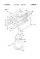
- FIG. 1shows an exploded perspective view of a mounting clip system according to the principles of the present invention with a cylindrical member removed and a retaining pin partially removed;
- FIG. 2shows a perspective view of the housing and retaining pin for the mounting clip system shown in FIG. 1 with the retaining pin positioned at a first side of a slot formed in the housing;
- FIG. 3is top sectional view of the housing for the mounting clip system shown in FIG. 1 taken through the slot in the housing;
- FIG. 4is a top view of the retaining pin for the mounting clip system shown in FIG. 1;
- FIG. 5is a perspective view of the housing for the mounting clip system shown in FIG. 1 with the slot and the retaining pin inserted in the slot shown in phantom;
- FIG. 6is a top sectional view of the mounting clip system shown in FIG. 1 taken through the slot with the retaining engaging the cylindrical member;
- FIG. 7shows a side sectional view of the mounting clip system with the cylindrical member retained by the pin in the housing, according to the principles of the present invention.
- the mounting clip systemincludes a stud member a housing 40 and a retaining pin 50.
- the stud member 30is cylindrical and includes a widened base portion 32 at a first end of the member 30.
- the base 32generally mounts against the mounting surface and may be welded, glued, integrally formed into the surface, or otherwise attached.
- a shaft portion 38extends upward from the base 32 to a second end 34.
- the second end 34includes a tapering portion 36 which provides alignment for easier assembly, as explained hereinafter.
- Below the tapered portion 36is an annular channel 37 extending around the periphery of the shaft portion 38.
- the housingincludes 40 a slot 44 extending therethrough transverse to the mounting axis of the stud 30, as also shown in FIG. 7.
- the slot 44includes a widened lower portion 46 and a narrow portion 48.
- the widened portion 46is configured for receiving the pin 50
- the narrow portion 48is configured for receiving the second end 34 of the cylindrical member 30.
- the narrow portion 48has an upper surface 72 and angled sides 74 and an end 76 to receive and substantially align the tapered end portion 36 of the stud member 30.
- the slot 44intercepts an orifice 80 extending from the underside of the housing 40.
- the orifice 80has a diameter substantially equal to the outer diameter of the shaft portion 38 of the cylindrical member 30.
- the slot 44includes a widened first end 64 and a narrowed second end 62 at the lower slot portion.
- the widened end 64is of a width capable of receiving the entire portion of the pin 50, while the narrow opening at the second end 62 receives only the narrowed end of the pin 50, as explained hereinafter.
- the housing 40includes a recess 66 extending from the upper surface 42 to the narrowed opening 62 in the slot 44.
- the slot 44also includes barbs 60a and 60b at either side of the narrowed opening at the second end 62, as shown again in FIGS. 3 and 6.
- the lower portion of the housing 40includes a retaining surface 68 inside retaining portions 70, as shown in FIGS. 1, 3 and 5.
- the pin 50includes extended leg portions 52a and 52b which spread outward from a longitudinal axis of the pin 50 in a substantially mirror image.
- the legs 52a and 52binclude hook portions, which are configured for engaging the barbs 60a and 60b, as explained hereinafter.
- the legs 52a and 52bconverge to a narrow portion and then diverge to form a stud member receiving section 54 with an enlarged opening.
- the pin 50then converges at a second point along the pin's longitudinal axis and diverges slightly to form a head portion 56 opposite the leg portions 52.
- the cylindrical member 30attaches to a mounting surface. If the article being retained against the mounting surface is slidably retained, the article would include a slot for receiving the stud 30. Several retainer clips 20 may be linearly aligned with several corresponding slots formed in the article providing for sliding movement of the retained article within a limited range. If the retained article in not slidably mounted, it can be appreciated that the housing 40 may be integrally formed as part of the retained article. When the article has been placed on the cylindrical member, the housing 40 may be attached.
- the pin 50Prior to assembly of the housing 40 to the cylindrical member 30, the pin 50 is inserted into the widened portion 46 of the slot 44. As shown in FIG. 2, the pin 50 is aligned with the head portion 56 facing toward the narrowed opening 62 of the slot 44 and the pin 50 is slid into the widened portion 64 of the slot 44. The pin 50 is aligned so that the stud receiving section 54 is aligned with the orifice 80, as shown in FIG. 5. The housing 40 is then pressed onto the stud 30. The tapering end portion 36 engages the stud receiving section 54, which flexes slightly outward. The legs at the stud receiving section 54 are spread outward sufficiently so that the stud 30 is inserted until the pin 50 aligns with the channel 37.
- the stud receiving section 54springs inward to its normal position and into the channel 37, as shown in FIGS. 6 and 7. If an attempt is made to pull the stud 30 outward in this position, the pin 50 engages the straight sides of the channel 37 and prevents removal of the stud 30.
- the housingmay also be mounted to the stud 30 in an alternative method wherein the pin 50 is first slid substantially entirely into the housing slot 44 until the head portion 56 extends out beyond the narrowed opening 62 of the slot 44, as shown in FIG. 1. In this position, the ends of the leg portions 52a and 52b engage the barb portions 60a and 60b in the slot 44. With the leg portions 52a and 52b engaging the barb portions 60a and 60b, the pin 50 cannot be pulled through the narrowed opening 62.
- the orifice 80is uncovered and can freely accept the stud member 30.
- the housing 40is slid onto the stud member 30 until the second end 34 engages the upper surface of the slot 44.
- the annular channel 37 formed in the shaft 38is substantially aligned with the widened lower portion 46 of the slot 44.
- the pin 50is also aligned with the annular channel 37. To engage the channel 37 with the pin 50, the pin 50 may be slid from the position shown in FIG. 1 to the retaining position, shown in FIGS. 6 and 7.
- the stud receiving section 54 of the pin 50encompasses the annular channel 37 of the cylindrical member 30.
- the converging portions at either end of the stud receiving section 54bias against the annular channel 37 and retain the pin 50 against the cylindrical member 30. Since the shaft portion 38 has a wider diameter than the opening of the stud receiving section 54, the stud member 30 may not be removed from engagement with the pin 50 and is retained in the housing 40.
- the head portion 56 of the pin 50extends beyond the opening 62 and beyond the edge of the housing 40. It will be appreciated that should the housing 40 need to be removed from the stud member 30, the pin 50 may be gripped by the head 56. If need be, a tool or pin may be inserted into the recess 66 and between the head 56 and the housing 40 to pry the pin 50 to a position disengaging the stud member 30, as shown in FIG. 1. This provides for easily removing the pin 50 from engagement with the stud 30 and for reinserting the pin 50 to engage the stud 30, as explained above. In this manner, the pin 50 is retained in the slot 44 and may be used over and over again as the housing 40 is removed and replaced on the stud member 30.
- a bottom retaining surface 68typically engages the upper surface of the latch bar or other device while side portions 70 extend on either side of the bar to align the latch bar or other article. It can be appreciated that this system provides for alignment of the article being retained and also allows for sliding relative to the mounting clip 20.
- the second end of the cylindrical member 34engages the upper surface 72 of the slot 44.
- the tapered portion 36 of the cylindrical member 30engages the angled side portion 74 and the angled end portion 76.
- the surfaces 74 and 76align and guide the stud member 30 into proper position and limit relative movement between the stud 30 and the housing 40.
- the pin 50inserts into the widened portion 46 of the slot 48 and engages the annular groove 37. In this position, the head 56 of the pin 50 extends slightly beyond the edge of the housing 40.
- the recess 66provides for inserting a tool through the center of the head portion 56 or otherwise gripping the pin 50 for pulling the pin outward to disengage the stud member 30 for separating the stud 30 from the housing 40.
- the barbs 60a and 60bengage the legs portions 52a and 52b to prevent separation of the pin 50 from the housing 40 and provide for replacing the housing 40 on the stud 30 and reusing all components.
Landscapes
- Engineering & Computer Science (AREA)
- General Engineering & Computer Science (AREA)
- Mechanical Engineering (AREA)
- Snaps, Bayonet Connections, Set Pins, And Snap Rings (AREA)
- Insertion Pins And Rivets (AREA)
Abstract
Description
Claims (19)
Priority Applications (4)
| Application Number | Priority Date | Filing Date | Title |
|---|---|---|---|
| US08/609,735US5704100A (en) | 1996-03-01 | 1996-03-01 | Retaining clip system |
| DE19707634ADE19707634B4 (en) | 1996-03-01 | 1997-02-26 | holding system |
| FR9702580AFR2745612B1 (en) | 1996-03-01 | 1997-02-26 | RETENTION CLIP SYSTEM |
| JP9065550AJPH10141340A (en) | 1996-03-01 | 1997-03-03 | Member holding device |
Applications Claiming Priority (1)
| Application Number | Priority Date | Filing Date | Title |
|---|---|---|---|
| US08/609,735US5704100A (en) | 1996-03-01 | 1996-03-01 | Retaining clip system |
Publications (1)
| Publication Number | Publication Date |
|---|---|
| US5704100Atrue US5704100A (en) | 1998-01-06 |
Family
ID=24442112
Family Applications (1)
| Application Number | Title | Priority Date | Filing Date |
|---|---|---|---|
| US08/609,735Expired - Fee RelatedUS5704100A (en) | 1996-03-01 | 1996-03-01 | Retaining clip system |
Country Status (4)
| Country | Link |
|---|---|
| US (1) | US5704100A (en) |
| JP (1) | JPH10141340A (en) |
| DE (1) | DE19707634B4 (en) |
| FR (1) | FR2745612B1 (en) |
Cited By (81)
| Publication number | Priority date | Publication date | Assignee | Title |
|---|---|---|---|---|
| US5957543A (en)* | 1997-10-20 | 1999-09-28 | Wu; Ching-Chang | Structure of golf cart wheel holder assembly |
| US6125588A (en)* | 1999-10-25 | 2000-10-03 | Daimlerchrysler Corporation | Glass attachment system for window regulator systems |
| US6290621B1 (en)* | 1999-04-15 | 2001-09-18 | Shimano Inc. | Derailleur for a bicycle |
| US6354119B1 (en) | 1999-11-24 | 2002-03-12 | Austin Hardware, Inc. | Handle and lock |
| BE1013678A3 (en)* | 2000-09-20 | 2002-06-04 | Power Climber Bv Met Beperkte | Improvements to workmen's cradles |
| GB2375158A (en)* | 2001-05-04 | 2002-11-06 | Sunonwealth Electr Mach Ind Co | Shaft retaining notch |
| US6494509B2 (en) | 1998-03-13 | 2002-12-17 | Austin Hardware, Inc. | Latch assembly |
| US20020193043A1 (en)* | 1999-03-15 | 2002-12-19 | Maor Avni | Top having two handles |
| US6502872B1 (en) | 1998-10-09 | 2003-01-07 | Austin Hardware, Inc. | Latch assembly |
| US6532778B2 (en) | 2000-10-23 | 2003-03-18 | Allegis Corporation | Double lock T-handle assembly |
| US6557220B1 (en)* | 2002-05-31 | 2003-05-06 | B. A. Ballou & Co., Inc. | Security clutch with self-centering spring |
| US6571436B2 (en)* | 2000-08-19 | 2003-06-03 | A. Raymond & Cie | Holding clip for mounting functional elements on a bolt |
| US6701588B2 (en)* | 2002-02-07 | 2004-03-09 | Sony Ericsson Mobile Communications Ab | Pin lock |
| WO2004036063A1 (en)* | 2002-10-15 | 2004-04-29 | Genesis Mining Technologies (Proprietary) Limited | Clip for pick in a pick holder |
| FR2856118A1 (en)* | 2003-06-10 | 2004-12-17 | Neyr Plastiques Holding | Axle and pedal lever connection device for vehicle, has pin moving between stable rest position, and stable locking position in which it is maintained in guiding module in position, where branches are engaged in groove of axle |
| EP1493629A1 (en)* | 2003-07-02 | 2005-01-05 | ITW Fixfast AB | Fastening element, arrangement and process for securing a panel |
| WO2005005780A1 (en)* | 2003-07-14 | 2005-01-20 | Zenon Wasyleczko | Clamp for mining rotating cutting insert |
| US20050019133A1 (en)* | 2003-07-21 | 2005-01-27 | Allen Joseph R. | Mounting device for securing an electronic device to an equipment rack |
| US20050031236A1 (en)* | 2003-06-13 | 2005-02-10 | Masato Gomyo | Conical hydrodynamic bearing device and a recording disk drive equipped with it, and a method of manufacturing a conical hydrodynamic bearing device |
| US6884101B2 (en)* | 2001-10-17 | 2005-04-26 | Hewlett-Packard Development Company, L.P. | Interposer one-step load and self-lock socket |
| US6952940B2 (en) | 2000-10-23 | 2005-10-11 | Allegis Corporation | Double lock T-handle assembly |
| US20060216132A1 (en)* | 2005-03-23 | 2006-09-28 | Tam Le | Panel fastener with spring retaining ring |
| US7128514B1 (en)* | 2005-04-08 | 2006-10-31 | Yazaki North America, Inc. | Adjustable and reusable stud bolt retainer |
| US20060291977A1 (en)* | 2005-06-24 | 2006-12-28 | Smith Kelly K | Captive screw with deployable knob |
| US20070029460A1 (en)* | 2005-08-08 | 2007-02-08 | Stefan Fitzler | Arrangement for axial securing of grooved bolt |
| US20070048080A1 (en)* | 2005-08-31 | 2007-03-01 | World Wide Stationery Mfg. Co., Ltd. | Ring binder having a clip |
| US20070048075A1 (en)* | 2005-08-31 | 2007-03-01 | Cheng Hung Y | Ring binder mechanism having slide connector |
| US20070071578A1 (en)* | 2005-09-20 | 2007-03-29 | Piolax, Inc. | Shaft fixing clip and shaft fixing structure using the clip |
| US20070130726A1 (en)* | 2005-12-09 | 2007-06-14 | Industrilas Ab | Hinge and latch mechanism |
| US20070157789A1 (en)* | 2006-01-12 | 2007-07-12 | Kim Dong J | Locking bridge |
| US20070157790A1 (en)* | 2006-01-12 | 2007-07-12 | Kim Dong J | Locking tailpiece |
| US20070240279A1 (en)* | 2006-04-18 | 2007-10-18 | Yi-Cheng Tan | Detachable wheel structure of baby carriage |
| US7296523B1 (en) | 2003-12-12 | 2007-11-20 | Unisys Corporation | Space-saving mounting table for use with an equipment rack |
| US20070296263A1 (en)* | 2005-08-02 | 2007-12-27 | Smith David S | Coupling Assembly |
| US7360659B1 (en)* | 2003-12-12 | 2008-04-22 | Unisys Corporation | Space-saving mounting fixture for use with an equipment rack |
| US7380889B2 (en)* | 2004-07-07 | 2008-06-03 | Frear Joseph K | Tool retainer |
| CN100402871C (en)* | 2005-09-09 | 2008-07-16 | 金宝电子工业股份有限公司 | Shaft fastening device |
| CN100422575C (en)* | 2004-04-22 | 2008-10-01 | 株式会社鹭宫制作所 | Anti-loose connection structure and valve device |
| US20090016846A1 (en)* | 2007-07-09 | 2009-01-15 | Dragonstate Technology Co., Ltd. | Anchor structure for electronic card connectors |
| US20090127874A1 (en)* | 2007-11-19 | 2009-05-21 | Ventfabrics, Inc. | Door latch assembly |
| US20090133571A1 (en)* | 2005-06-03 | 2009-05-28 | Armatec Survivability Corp. | Armor mounting system |
| US20090208307A1 (en)* | 2008-02-18 | 2009-08-20 | Guyton Jason D | Releasable Fastener Systems and Methods |
| US20090293242A1 (en)* | 2008-06-02 | 2009-12-03 | Joy Mm Delaware, Inc. | Clip for pin retention |
| US20100122434A1 (en)* | 2008-11-19 | 2010-05-20 | Chao-Chi Lin | Advertising Device Used in a Hinge Assembly |
| CN101253357B (en)* | 2005-08-30 | 2010-12-29 | 卢克摩擦片和离合器两合公司 | Hydraulic coupling with a bayonet closure and a wire-form spring for rotational locking |
| US20110067225A1 (en)* | 2009-09-24 | 2011-03-24 | Bassaco Arnaldo R | Hydraulic line connector |
| US20110237104A1 (en)* | 2008-08-21 | 2011-09-29 | Labinal | Connection device between an electrical cable and a conducting structure, especially for a current return circuit |
| US8226130B2 (en) | 2005-12-09 | 2012-07-24 | Industrilås i NässjöAB | Control roller mechanism-activator |
| US20120224915A1 (en)* | 2011-03-03 | 2012-09-06 | Tyc Brother Industrial Co., Ltd. | Securing device for connecting reflector to adjustment unit of vehicle headlight |
| CN102811580A (en)* | 2011-05-31 | 2012-12-05 | 深圳富泰宏精密工业有限公司 | Gasket, connecting module applying same and sliding mechanism |
| WO2013003738A1 (en)* | 2011-06-30 | 2013-01-03 | Blackstone Medical, Inc. | Spring device for locking an expandable support device |
| US8690886B2 (en) | 2011-06-30 | 2014-04-08 | Blackston Medical, Inc. | Posterior insertion instrument for an expandable support device |
| US20140119817A1 (en)* | 2012-11-01 | 2014-05-01 | Kindwin Opto Electronics (Shenzhen) Ltd. | Coaxial tensionable automatic lock |
| US20140187063A1 (en)* | 2012-12-31 | 2014-07-03 | Suunto Oy | Male end of a telemetric transceiver |
| WO2014121185A1 (en)* | 2013-02-01 | 2014-08-07 | Anthony Hardwood Composites, Inc. | Construction mat fasteners for joining mats together |
| US20140301672A1 (en)* | 2011-11-04 | 2014-10-09 | James Patrick Bowerman | Clasp |
| US20150020644A1 (en)* | 2013-03-19 | 2015-01-22 | Kidkraft, Lp | Screwless knob assembly for toys |
| CN104379959A (en)* | 2014-03-31 | 2015-02-25 | 深圳市大疆创新科技有限公司 | Damping device and aircraft employing same |
| DE102013225429A1 (en)* | 2013-12-10 | 2015-06-11 | Siemens Medical Instruments Pte. Ltd. | BTE hearing instrument with housing and carrying hook |
| WO2015148690A1 (en)* | 2014-03-27 | 2015-10-01 | C&D Zodiac, Inc. | Fastener system |
| US20160025126A1 (en)* | 2013-06-25 | 2016-01-28 | Bayerische Motoren Werke Aktiengesellschaft | Component Connection |
| EP3009728A1 (en)* | 2014-10-17 | 2016-04-20 | Ondal Medical Systems GmbH | Retaining element for stand device and correspondingly formed components |
| US9428259B2 (en) | 2014-03-27 | 2016-08-30 | C&D Zodiac, Inc. | Bi-fold door module |
| USD773339S1 (en)* | 2015-03-25 | 2016-12-06 | C&D Zodiac, Inc. | Fastener system |
| US20170187130A1 (en)* | 2015-12-24 | 2017-06-29 | Audi Ag | Electrical connection element |
| RU179831U1 (en)* | 2017-02-07 | 2018-05-25 | Общество с ограниченной ответственностью "Горный инструмент" | STOPPING TANGENTIAL SWIVEL CUTTER |
| US9986794B2 (en) | 2009-06-03 | 2018-06-05 | Bibboards, Inc. | Fastener |
| US10113317B1 (en)* | 2015-04-16 | 2018-10-30 | Gordon Sales, Inc. | Apparatus and method for hanging architectural panels with concealed attachment points |
| US10443643B2 (en)* | 2015-06-23 | 2019-10-15 | A. Raymond Et Cie | Fastening device with high pull-out strength |
| US10511205B2 (en) | 2015-07-03 | 2019-12-17 | Robotis Co., Ltd. | Device for attaching/detaching idler horn for actuator module |
| USD877606S1 (en)* | 2018-01-10 | 2020-03-10 | Jennmar SanShell, LLC | Retaining clip |
| USD878911S1 (en)* | 2018-09-21 | 2020-03-24 | Steven M Cox | Leash coupler |
| USD885876S1 (en)* | 2018-01-10 | 2020-06-02 | Jennmar SanShell, LLC | Retaining clip |
| US10723212B2 (en)* | 2017-01-13 | 2020-07-28 | Nio Co., Ltd. | Quick locking-unlocking assembly |
| US20200246108A1 (en)* | 2019-01-31 | 2020-08-06 | American Sterilizer Company | Modular adapters for medical device support system |
| US10792805B2 (en)* | 2017-01-18 | 2020-10-06 | Robotis Co., Ltd. | Semi-hollow actuator module |
| US20220344191A1 (en)* | 2021-04-23 | 2022-10-27 | Taiwan Semiconductor Manufacturing Company Limited | Wafer pod transfer assembly |
| US11524788B2 (en)* | 2018-09-19 | 2022-12-13 | Airbus Operations Gmbh | Floor fixing assembly with clamping split pin |
| IT202100022445A1 (en)* | 2021-08-27 | 2023-02-27 | Feda S R L | Mechanical linkage system |
| US11661726B2 (en) | 2019-09-13 | 2023-05-30 | Komatsu Ltd. | Tooth attachment structure for bucket and tooth for bucket |
| US20230340762A1 (en)* | 2022-04-26 | 2023-10-26 | Caterpillar Inc. | Front access for bit retention |
Families Citing this family (19)
| Publication number | Priority date | Publication date | Assignee | Title |
|---|---|---|---|---|
| DE10036611C2 (en)* | 2000-07-27 | 2002-12-05 | Faurecia Autositze Gmbh & Co | Device for locking a foldable seat part of a motor vehicle rear seat |
| DE102004060789B4 (en)* | 2004-12-17 | 2008-12-18 | Fairchild Fasteners Europe - Camloc Gmbh | closure device |
| DE102005002853B3 (en)* | 2005-01-20 | 2006-04-27 | Johnson Controls Gmbh | Bolt axial fixing device for motor vehicle, has wire shaped safety device loosely accommodated with slot, and axial force for loosening safety device is changed based on function of turning position relative to bolt or wave |
| DE102005022719B3 (en)* | 2005-05-18 | 2006-11-30 | Wilhelm Karmann Gmbh | Connecting arrangement e.g. for motor vehicle, has first hole having mounting plate, longitudinal axis and pins enclosed in hole |
| DE202005020308U1 (en) | 2005-12-27 | 2007-05-03 | S-Fasteners Gmbh | decompression |
| DE202005020309U1 (en) | 2005-12-27 | 2007-05-10 | S-Fasteners Gmbh | Connecting arrangement for superimposed layers of material |
| DE202006004081U1 (en)* | 2006-03-13 | 2007-08-02 | S-Fasterners Gmbh | Arrangement for the detachable attachment of components to a ceiling or wall |
| DE202006019165U1 (en) | 2006-12-20 | 2008-05-08 | S-Fasteners Gmbh | Arrangement with a locking element for a locking hook |
| DE202007000112U1 (en) | 2007-01-02 | 2008-05-15 | S-Fasteners Gmbh | Locking arrangement with a pivotable locking hook and a sliding support rod |
| DE102008022253A1 (en) | 2008-05-06 | 2009-11-12 | Miva Technologies Gmbh | High-resolution photoplotting method and arrangement for the high-resolution recording of a computer-stored raster image on a planar photosensitive recording medium |
| JP4985578B2 (en)* | 2008-07-29 | 2012-07-25 | トヨタ自動車株式会社 | Article mounting structure |
| KR101106886B1 (en) | 2008-12-12 | 2012-01-25 | 두산디에스티주식회사 | Bracket Unit with Locking Pin |
| KR101115067B1 (en)* | 2009-05-14 | 2012-02-28 | 이규원 | Servo Actuator Module for Easy to Separate and Attach of Idle Flange |
| AT513865B1 (en)* | 2013-02-01 | 2014-12-15 | Hirtenberger Automotive Safety | actuator |
| DE102013205693A1 (en)* | 2013-03-28 | 2014-10-02 | B & K Braun Gmbh | BETWEEN CONNECTOR |
| FR3025467B1 (en)* | 2014-09-08 | 2017-12-08 | Olivier Chaduteau | DEVICE FOR FASTENING A REPORTED ELEMENT OF A VEHICLE, ELEMENT REPORTED FROM A VEHICLE COMPRISING A PORTION OF SAID FIXING DEVICE |
| EP3205781A1 (en)* | 2016-02-12 | 2017-08-16 | Metalogenia Research & Technologies S.L. | Female part, retaining device and pin system for excavators and the like |
| DE102018001137B3 (en) | 2018-02-13 | 2019-04-25 | Psa Automobiles Sa | Engine assembly |
| CN112109535B (en)* | 2020-08-25 | 2022-02-01 | 东风汽车集团有限公司 | Battery locking mechanism |
Citations (14)
| Publication number | Priority date | Publication date | Assignee | Title |
|---|---|---|---|---|
| US641234A (en)* | 1899-07-03 | 1900-01-09 | Mary Olive Ross | Corset-fastener. |
| US1160190A (en)* | 1914-11-05 | 1915-11-16 | William Paul Joseph Murray | Paper-clip. |
| GB287753A (en)* | 1927-06-23 | 1928-03-29 | Johannes Wilhelm Hofmann | Improvements in or relating to electric insulator suspension devices |
| US1764950A (en)* | 1928-05-03 | 1930-06-17 | Harry B Griner | Fastener for awnings |
| US1976623A (en)* | 1933-05-24 | 1934-10-09 | Stanley G Monroe | Jar clamping tool |
| CH452958A (en)* | 1967-07-10 | 1968-03-15 | Aubry Louis | Clamp for supporting and retaining an object |
| US3505709A (en)* | 1968-01-25 | 1970-04-14 | James F Tirone | Quick release clip |
| US4716632A (en)* | 1987-03-03 | 1988-01-05 | Voplex Corporation | Panel mounting fastener system |
| US4733987A (en)* | 1986-02-27 | 1988-03-29 | Tomlinson Peter N | Spring clip |
| DE3710563A1 (en)* | 1987-03-30 | 1988-10-20 | Loh Kg Rittal Werk | CONTROL CABINET WITH CABINET BODY AND HINGED CABINET DOOR |
| US5172944A (en)* | 1991-11-27 | 1992-12-22 | Federal-Hoffman, Inc. | Multiple point cam-pinion door latch |
| DE9305893U1 (en)* | 1993-04-20 | 1993-06-17 | Dirak Konstruktionselemente GmbH & Co. KG, 5830 Schwelm | Locking device for doors of enclosures or cabinets |
| US5433930A (en)* | 1988-10-06 | 1995-07-18 | Aesculap Ag | Screen basket for sterilizating containers |
| US5451082A (en)* | 1992-08-12 | 1995-09-19 | Yoshida Kogyo K.K. | Lock fastener |
Family Cites Families (1)
| Publication number | Priority date | Publication date | Assignee | Title |
|---|---|---|---|---|
| FR1231735A (en)* | 1959-04-13 | 1960-10-03 | Simca | Linkage connection |
- 1996
- 1996-03-01USUS08/609,735patent/US5704100A/ennot_activeExpired - Fee Related
- 1997
- 1997-02-26FRFR9702580Apatent/FR2745612B1/ennot_activeExpired - Fee Related
- 1997-02-26DEDE19707634Apatent/DE19707634B4/ennot_activeExpired - Fee Related
- 1997-03-03JPJP9065550Apatent/JPH10141340A/enactivePending
Patent Citations (14)
| Publication number | Priority date | Publication date | Assignee | Title |
|---|---|---|---|---|
| US641234A (en)* | 1899-07-03 | 1900-01-09 | Mary Olive Ross | Corset-fastener. |
| US1160190A (en)* | 1914-11-05 | 1915-11-16 | William Paul Joseph Murray | Paper-clip. |
| GB287753A (en)* | 1927-06-23 | 1928-03-29 | Johannes Wilhelm Hofmann | Improvements in or relating to electric insulator suspension devices |
| US1764950A (en)* | 1928-05-03 | 1930-06-17 | Harry B Griner | Fastener for awnings |
| US1976623A (en)* | 1933-05-24 | 1934-10-09 | Stanley G Monroe | Jar clamping tool |
| CH452958A (en)* | 1967-07-10 | 1968-03-15 | Aubry Louis | Clamp for supporting and retaining an object |
| US3505709A (en)* | 1968-01-25 | 1970-04-14 | James F Tirone | Quick release clip |
| US4733987A (en)* | 1986-02-27 | 1988-03-29 | Tomlinson Peter N | Spring clip |
| US4716632A (en)* | 1987-03-03 | 1988-01-05 | Voplex Corporation | Panel mounting fastener system |
| DE3710563A1 (en)* | 1987-03-30 | 1988-10-20 | Loh Kg Rittal Werk | CONTROL CABINET WITH CABINET BODY AND HINGED CABINET DOOR |
| US5433930A (en)* | 1988-10-06 | 1995-07-18 | Aesculap Ag | Screen basket for sterilizating containers |
| US5172944A (en)* | 1991-11-27 | 1992-12-22 | Federal-Hoffman, Inc. | Multiple point cam-pinion door latch |
| US5451082A (en)* | 1992-08-12 | 1995-09-19 | Yoshida Kogyo K.K. | Lock fastener |
| DE9305893U1 (en)* | 1993-04-20 | 1993-06-17 | Dirak Konstruktionselemente GmbH & Co. KG, 5830 Schwelm | Locking device for doors of enclosures or cabinets |
Cited By (136)
| Publication number | Priority date | Publication date | Assignee | Title |
|---|---|---|---|---|
| US5957543A (en)* | 1997-10-20 | 1999-09-28 | Wu; Ching-Chang | Structure of golf cart wheel holder assembly |
| US6715807B2 (en) | 1998-03-13 | 2004-04-06 | Austin Hardware, Inc. | Latch assembly |
| US6494509B2 (en) | 1998-03-13 | 2002-12-17 | Austin Hardware, Inc. | Latch assembly |
| US6502872B1 (en) | 1998-10-09 | 2003-01-07 | Austin Hardware, Inc. | Latch assembly |
| US6702342B2 (en) | 1998-10-09 | 2004-03-09 | Austin Hardware, Inc. | Latch assembly |
| US20020193043A1 (en)* | 1999-03-15 | 2002-12-19 | Maor Avni | Top having two handles |
| US6290621B1 (en)* | 1999-04-15 | 2001-09-18 | Shimano Inc. | Derailleur for a bicycle |
| US6125588A (en)* | 1999-10-25 | 2000-10-03 | Daimlerchrysler Corporation | Glass attachment system for window regulator systems |
| US6662605B2 (en) | 1999-11-24 | 2003-12-16 | Austin Hardware, Inc. | Handle and lock |
| US6868703B2 (en) | 1999-11-24 | 2005-03-22 | Austin Hardware, Inc. | Handle and lock |
| US6354119B1 (en) | 1999-11-24 | 2002-03-12 | Austin Hardware, Inc. | Handle and lock |
| US20040079124A1 (en)* | 1999-11-24 | 2004-04-29 | Klaus Molzer | Handle and lock |
| US6571436B2 (en)* | 2000-08-19 | 2003-06-03 | A. Raymond & Cie | Holding clip for mounting functional elements on a bolt |
| BE1013678A3 (en)* | 2000-09-20 | 2002-06-04 | Power Climber Bv Met Beperkte | Improvements to workmen's cradles |
| US6532778B2 (en) | 2000-10-23 | 2003-03-18 | Allegis Corporation | Double lock T-handle assembly |
| US20060032277A1 (en)* | 2000-10-23 | 2006-02-16 | Allegis Corporation | Double lock T-handle assembly |
| US6952940B2 (en) | 2000-10-23 | 2005-10-11 | Allegis Corporation | Double lock T-handle assembly |
| GB2375158A (en)* | 2001-05-04 | 2002-11-06 | Sunonwealth Electr Mach Ind Co | Shaft retaining notch |
| US6884101B2 (en)* | 2001-10-17 | 2005-04-26 | Hewlett-Packard Development Company, L.P. | Interposer one-step load and self-lock socket |
| US6701588B2 (en)* | 2002-02-07 | 2004-03-09 | Sony Ericsson Mobile Communications Ab | Pin lock |
| WO2003101239A3 (en)* | 2002-05-31 | 2004-08-19 | Ballou & Co B A | Security clutch with self-centering spring |
| US6557220B1 (en)* | 2002-05-31 | 2003-05-06 | B. A. Ballou & Co., Inc. | Security clutch with self-centering spring |
| WO2004036063A1 (en)* | 2002-10-15 | 2004-04-29 | Genesis Mining Technologies (Proprietary) Limited | Clip for pick in a pick holder |
| FR2856118A1 (en)* | 2003-06-10 | 2004-12-17 | Neyr Plastiques Holding | Axle and pedal lever connection device for vehicle, has pin moving between stable rest position, and stable locking position in which it is maintained in guiding module in position, where branches are engaged in groove of axle |
| US20050031236A1 (en)* | 2003-06-13 | 2005-02-10 | Masato Gomyo | Conical hydrodynamic bearing device and a recording disk drive equipped with it, and a method of manufacturing a conical hydrodynamic bearing device |
| EP1493629A1 (en)* | 2003-07-02 | 2005-01-05 | ITW Fixfast AB | Fastening element, arrangement and process for securing a panel |
| WO2005005780A1 (en)* | 2003-07-14 | 2005-01-20 | Zenon Wasyleczko | Clamp for mining rotating cutting insert |
| US20050019133A1 (en)* | 2003-07-21 | 2005-01-27 | Allen Joseph R. | Mounting device for securing an electronic device to an equipment rack |
| US6955512B2 (en)* | 2003-07-21 | 2005-10-18 | Hewlett-Packard Development Company, L.P. | Mounting device for securing an electronic device to an equipment rack |
| US7360659B1 (en)* | 2003-12-12 | 2008-04-22 | Unisys Corporation | Space-saving mounting fixture for use with an equipment rack |
| US7296523B1 (en) | 2003-12-12 | 2007-11-20 | Unisys Corporation | Space-saving mounting table for use with an equipment rack |
| CN100422575C (en)* | 2004-04-22 | 2008-10-01 | 株式会社鹭宫制作所 | Anti-loose connection structure and valve device |
| US7380889B2 (en)* | 2004-07-07 | 2008-06-03 | Frear Joseph K | Tool retainer |
| US20060216132A1 (en)* | 2005-03-23 | 2006-09-28 | Tam Le | Panel fastener with spring retaining ring |
| US7204668B2 (en)* | 2005-03-23 | 2007-04-17 | Avibank Mfg., Inc. | Panel fastener with spring retaining ring |
| US7128514B1 (en)* | 2005-04-08 | 2006-10-31 | Yazaki North America, Inc. | Adjustable and reusable stud bolt retainer |
| US8757042B2 (en)* | 2005-06-03 | 2014-06-24 | 2040422 Ontario Inc. | Armor mounting system |
| US20090133571A1 (en)* | 2005-06-03 | 2009-05-28 | Armatec Survivability Corp. | Armor mounting system |
| US20060291977A1 (en)* | 2005-06-24 | 2006-12-28 | Smith Kelly K | Captive screw with deployable knob |
| US7241096B2 (en)* | 2005-06-24 | 2007-07-10 | Hewlett-Packard Development Company, L.P. | Captive screw with deployable knob |
| US20070296263A1 (en)* | 2005-08-02 | 2007-12-27 | Smith David S | Coupling Assembly |
| US7390068B2 (en)* | 2005-08-02 | 2008-06-24 | The Scott Fetzer Company | Coupling assembly for wheel and axle |
| US20070029460A1 (en)* | 2005-08-08 | 2007-02-08 | Stefan Fitzler | Arrangement for axial securing of grooved bolt |
| US7568855B2 (en) | 2005-08-08 | 2009-08-04 | Demag Cranes & Components Gmbh | Arrangement for axial securing of grooved bolt |
| CN101253357B (en)* | 2005-08-30 | 2010-12-29 | 卢克摩擦片和离合器两合公司 | Hydraulic coupling with a bayonet closure and a wire-form spring for rotational locking |
| US20070048075A1 (en)* | 2005-08-31 | 2007-03-01 | Cheng Hung Y | Ring binder mechanism having slide connector |
| US20070048080A1 (en)* | 2005-08-31 | 2007-03-01 | World Wide Stationery Mfg. Co., Ltd. | Ring binder having a clip |
| US7654765B2 (en) | 2005-08-31 | 2010-02-02 | World Wide Stationary Mfg. Co., Ltd. | Ring binder having a clip |
| US7513708B2 (en)* | 2005-08-31 | 2009-04-07 | World Wide Stationery Mfg. Co., Ltd. | Ring binder mechanism having slide connector |
| CN100402871C (en)* | 2005-09-09 | 2008-07-16 | 金宝电子工业股份有限公司 | Shaft fastening device |
| US7704008B2 (en)* | 2005-09-20 | 2010-04-27 | Piolax, Inc. | Shaft fixing clip and shaft fixing structure using the clip |
| US20070071578A1 (en)* | 2005-09-20 | 2007-03-29 | Piolax, Inc. | Shaft fixing clip and shaft fixing structure using the clip |
| US8226130B2 (en) | 2005-12-09 | 2012-07-24 | Industrilås i NässjöAB | Control roller mechanism-activator |
| US20070130726A1 (en)* | 2005-12-09 | 2007-06-14 | Industrilas Ab | Hinge and latch mechanism |
| US7761958B2 (en) | 2005-12-09 | 2010-07-27 | Allegris Corporation | Hinge and latch mechanism |
| US8161601B2 (en) | 2005-12-09 | 2012-04-24 | Industrilas Ab | Hinge and latch mechanism |
| US7459617B2 (en)* | 2006-01-12 | 2008-12-02 | Gibson Guitar Corp. | Locking bridge |
| US20070157789A1 (en)* | 2006-01-12 | 2007-07-12 | Kim Dong J | Locking bridge |
| US7459618B2 (en)* | 2006-01-12 | 2008-12-02 | Gibson Guitar Corp. | Locking tailpiece |
| US20070157790A1 (en)* | 2006-01-12 | 2007-07-12 | Kim Dong J | Locking tailpiece |
| US20070240279A1 (en)* | 2006-04-18 | 2007-10-18 | Yi-Cheng Tan | Detachable wheel structure of baby carriage |
| US20100317231A1 (en)* | 2007-07-09 | 2010-12-16 | Shih-Chia Lai | Anchor structure for electronic card connectors |
| US20090016846A1 (en)* | 2007-07-09 | 2009-01-15 | Dragonstate Technology Co., Ltd. | Anchor structure for electronic card connectors |
| US7819443B2 (en) | 2007-11-19 | 2010-10-26 | Ventfabrics, Inc. | Door latch assembly |
| US20090127874A1 (en)* | 2007-11-19 | 2009-05-21 | Ventfabrics, Inc. | Door latch assembly |
| US20090208307A1 (en)* | 2008-02-18 | 2009-08-20 | Guyton Jason D | Releasable Fastener Systems and Methods |
| US8221043B2 (en)* | 2008-02-18 | 2012-07-17 | Lockheed Martin Corporation | Releasable fastener systems and methods |
| US8348582B2 (en)* | 2008-06-02 | 2013-01-08 | Joy Mm Delaware, Inc. | Clip for pin retention |
| US20090293242A1 (en)* | 2008-06-02 | 2009-12-03 | Joy Mm Delaware, Inc. | Clip for pin retention |
| US8562371B2 (en)* | 2008-08-21 | 2013-10-22 | Labinal | Connection device between an electrical cable and a conducting structure, especially for a current return circuit |
| CN102132459B (en)* | 2008-08-21 | 2014-11-19 | 雷比诺公司 | Connection device between an electrical cable and a conducting structure, especially for a current return circuit |
| US20110237104A1 (en)* | 2008-08-21 | 2011-09-29 | Labinal | Connection device between an electrical cable and a conducting structure, especially for a current return circuit |
| US20100122434A1 (en)* | 2008-11-19 | 2010-05-20 | Chao-Chi Lin | Advertising Device Used in a Hinge Assembly |
| US9986794B2 (en) | 2009-06-03 | 2018-06-05 | Bibboards, Inc. | Fastener |
| US9273812B2 (en)* | 2009-09-24 | 2016-03-01 | Perfection Clutch | Hydraulic line connector |
| US10151412B2 (en) | 2009-09-24 | 2018-12-11 | Perfection Hy-Test Company | Hydraulic line connector |
| US20110067225A1 (en)* | 2009-09-24 | 2011-03-24 | Bassaco Arnaldo R | Hydraulic line connector |
| US20120224915A1 (en)* | 2011-03-03 | 2012-09-06 | Tyc Brother Industrial Co., Ltd. | Securing device for connecting reflector to adjustment unit of vehicle headlight |
| US8485706B2 (en)* | 2011-03-03 | 2013-07-16 | Tyc Brother Industrial Co., Ltd. | Securing device for connecting reflector to adjustment unit of vehicle headlight |
| CN102811580A (en)* | 2011-05-31 | 2012-12-05 | 深圳富泰宏精密工业有限公司 | Gasket, connecting module applying same and sliding mechanism |
| US20120308296A1 (en)* | 2011-05-31 | 2012-12-06 | Fih (Hong Kong) Limited | Conncting module and sliding mechanism for electronic device |
| US8453299B2 (en)* | 2011-05-31 | 2013-06-04 | Shenzhen Futaihong Precision Industry Co., Ltd. | Connecting module and sliding mechanism for electronic device |
| WO2013003738A1 (en)* | 2011-06-30 | 2013-01-03 | Blackstone Medical, Inc. | Spring device for locking an expandable support device |
| US8690886B2 (en) | 2011-06-30 | 2014-04-08 | Blackston Medical, Inc. | Posterior insertion instrument for an expandable support device |
| US8585763B2 (en) | 2011-06-30 | 2013-11-19 | Blackstone Medical, Inc. | Spring device for locking an expandable support device |
| US20140301672A1 (en)* | 2011-11-04 | 2014-10-09 | James Patrick Bowerman | Clasp |
| US9717308B2 (en)* | 2011-11-04 | 2017-08-01 | James Patrick Bowerman | Clasp |
| US20140119817A1 (en)* | 2012-11-01 | 2014-05-01 | Kindwin Opto Electronics (Shenzhen) Ltd. | Coaxial tensionable automatic lock |
| US9194415B2 (en)* | 2012-11-01 | 2015-11-24 | Kindwin Opto Electronic (Shenzhen) Co., Ltd. | Coaxial tensionable automatic lock |
| US8814574B2 (en)* | 2012-12-31 | 2014-08-26 | Suunto Oy | Male end of a telemetric transceiver |
| US20140187063A1 (en)* | 2012-12-31 | 2014-07-03 | Suunto Oy | Male end of a telemetric transceiver |
| WO2014121185A1 (en)* | 2013-02-01 | 2014-08-07 | Anthony Hardwood Composites, Inc. | Construction mat fasteners for joining mats together |
| US20150020644A1 (en)* | 2013-03-19 | 2015-01-22 | Kidkraft, Lp | Screwless knob assembly for toys |
| US20160025126A1 (en)* | 2013-06-25 | 2016-01-28 | Bayerische Motoren Werke Aktiengesellschaft | Component Connection |
| US10718367B2 (en)* | 2013-06-25 | 2020-07-21 | Bayerische Motoren Werke Aktiengesellschaft | Component connection |
| DE102013225429A1 (en)* | 2013-12-10 | 2015-06-11 | Siemens Medical Instruments Pte. Ltd. | BTE hearing instrument with housing and carrying hook |
| US9994320B2 (en) | 2014-03-27 | 2018-06-12 | C&D Zodiac, Inc. | Bi-fold door module |
| RU2679976C2 (en)* | 2014-03-27 | 2019-02-14 | Си Энд Ди ЗОДИАК, ИНК. | Fastener system |
| US9428259B2 (en) | 2014-03-27 | 2016-08-30 | C&D Zodiac, Inc. | Bi-fold door module |
| CN106132822A (en)* | 2014-03-27 | 2016-11-16 | C&D佐迪阿克公司 | Fastener system |
| CN109178288A (en)* | 2014-03-27 | 2019-01-11 | C&D佐迪阿克公司 | Fastener system |
| US9562549B2 (en) | 2014-03-27 | 2017-02-07 | C&D Zodiac, Inc. | Fastener system |
| US9638233B1 (en) | 2014-03-27 | 2017-05-02 | C&D Zodiac, Inc. | Fastener system |
| WO2015148690A1 (en)* | 2014-03-27 | 2015-10-01 | C&D Zodiac, Inc. | Fastener system |
| CN109178288B (en)* | 2014-03-27 | 2022-03-01 | 赛峰客舱公司 | Fastener system |
| CN104379959A (en)* | 2014-03-31 | 2015-02-25 | 深圳市大疆创新科技有限公司 | Damping device and aircraft employing same |
| EP3207300B1 (en)* | 2014-10-17 | 2022-09-07 | Ondal Medical Systems GmbH | Retaining element for stand device and correspondingly formed components |
| CN106999333A (en)* | 2014-10-17 | 2017-08-01 | 欧达尔医疗系统有限责任公司 | Retaining element and the component being correspondingly formed for stand arrangement |
| US10080696B2 (en) | 2014-10-17 | 2018-09-25 | Ondal Medical Systems Gmbh | Securing element for stand device and correspondingly formed components |
| WO2016058705A3 (en)* | 2014-10-17 | 2016-06-09 | Ondal Medical Systems Gmbh | Securing element for a stand device and components designed in correspondence therewith |
| EP3009728A1 (en)* | 2014-10-17 | 2016-04-20 | Ondal Medical Systems GmbH | Retaining element for stand device and correspondingly formed components |
| CN106999333B (en)* | 2014-10-17 | 2020-01-03 | 欧达尔医疗系统有限责任公司 | Fastening element for a rack device and correspondingly formed component |
| USD773339S1 (en)* | 2015-03-25 | 2016-12-06 | C&D Zodiac, Inc. | Fastener system |
| US10113317B1 (en)* | 2015-04-16 | 2018-10-30 | Gordon Sales, Inc. | Apparatus and method for hanging architectural panels with concealed attachment points |
| US12049758B1 (en) | 2015-04-16 | 2024-07-30 | Gordon Sales, Inc. | Apparatus and method for hanging architectural panels with concealed attachment points |
| US11168477B1 (en) | 2015-04-16 | 2021-11-09 | Gordon Sales, Inc. | Apparatus and method for hanging architectural panels with concealed attachment points |
| US10443643B2 (en)* | 2015-06-23 | 2019-10-15 | A. Raymond Et Cie | Fastening device with high pull-out strength |
| US10511205B2 (en) | 2015-07-03 | 2019-12-17 | Robotis Co., Ltd. | Device for attaching/detaching idler horn for actuator module |
| US20170187130A1 (en)* | 2015-12-24 | 2017-06-29 | Audi Ag | Electrical connection element |
| US9997848B2 (en)* | 2015-12-24 | 2018-06-12 | Audi Ag | Electrical connection element |
| US10723212B2 (en)* | 2017-01-13 | 2020-07-28 | Nio Co., Ltd. | Quick locking-unlocking assembly |
| US10792805B2 (en)* | 2017-01-18 | 2020-10-06 | Robotis Co., Ltd. | Semi-hollow actuator module |
| RU179831U1 (en)* | 2017-02-07 | 2018-05-25 | Общество с ограниченной ответственностью "Горный инструмент" | STOPPING TANGENTIAL SWIVEL CUTTER |
| USD877606S1 (en)* | 2018-01-10 | 2020-03-10 | Jennmar SanShell, LLC | Retaining clip |
| USD885876S1 (en)* | 2018-01-10 | 2020-06-02 | Jennmar SanShell, LLC | Retaining clip |
| US11524788B2 (en)* | 2018-09-19 | 2022-12-13 | Airbus Operations Gmbh | Floor fixing assembly with clamping split pin |
| USD878911S1 (en)* | 2018-09-21 | 2020-03-24 | Steven M Cox | Leash coupler |
| US10874477B2 (en)* | 2019-01-31 | 2020-12-29 | American Sterilizer Company | Modular adapters for medical device support system |
| US20200246108A1 (en)* | 2019-01-31 | 2020-08-06 | American Sterilizer Company | Modular adapters for medical device support system |
| US11661726B2 (en) | 2019-09-13 | 2023-05-30 | Komatsu Ltd. | Tooth attachment structure for bucket and tooth for bucket |
| DE112020003816B4 (en) | 2019-09-13 | 2023-06-29 | Komatsu Ltd. | Tooth attachment structure for spoon and tooth for spoon |
| US11600506B2 (en)* | 2021-04-23 | 2023-03-07 | Taiwan Semiconductor Manufacturing Company Limited | Wafer pod transfer assembly |
| US20220344191A1 (en)* | 2021-04-23 | 2022-10-27 | Taiwan Semiconductor Manufacturing Company Limited | Wafer pod transfer assembly |
| WO2023026176A1 (en)* | 2021-08-27 | 2023-03-02 | Feda S.R.L. | Mechanical connection system |
| IT202100022445A1 (en)* | 2021-08-27 | 2023-02-27 | Feda S R L | Mechanical linkage system |
| US20230340762A1 (en)* | 2022-04-26 | 2023-10-26 | Caterpillar Inc. | Front access for bit retention |
Also Published As
| Publication number | Publication date |
|---|---|
| DE19707634A1 (en) | 1997-10-30 |
| DE19707634B4 (en) | 2005-10-13 |
| JPH10141340A (en) | 1998-05-26 |
| FR2745612A1 (en) | 1997-09-05 |
| FR2745612B1 (en) | 2000-02-11 |
Similar Documents
| Publication | Publication Date | Title |
|---|---|---|
| US5704100A (en) | Retaining clip system | |
| US4786119A (en) | Locking clip for securing a bolt holding panel members together | |
| US5022156A (en) | Handle fastener assembly and method of making same | |
| US5722121A (en) | Enclosure hinge | |
| US5113727A (en) | Pliers with removable jaw inserts | |
| KR102574618B1 (en) | strap attachment | |
| US5387065A (en) | Reusable pin and grommet fastner | |
| EP3681349B1 (en) | Furniture securing device | |
| US6345747B1 (en) | Strap assembly | |
| US20050269921A1 (en) | Wire baskets and related devices | |
| EP0776817A2 (en) | Bicycle lock bracket | |
| US5988667A (en) | Anti-rattle device for a trailer hitch | |
| US20030121130A1 (en) | Mounting structure | |
| EP0588537A1 (en) | Swivelling snaphook | |
| US6588639B2 (en) | Molded holster belt loop assembly with shelf | |
| US20040016712A1 (en) | Spring loaded bracket assembly having a tool-less attachment and removal feature | |
| US7878547B2 (en) | Seatbelt anchor assembly | |
| EP0729541A1 (en) | Hinge system | |
| EP2822881B1 (en) | Assembly of a module and a mounting frame for a modular conveyor and conveyor comprising such an assembly | |
| USRE37530E1 (en) | Method and kit for attaching side shields to eyeglass temples | |
| US20020100149A1 (en) | Low profile integrated omega zipper closure system | |
| CN115990849A (en) | Fixing device | |
| JPH01288605A (en) | Spring type fixing panel stop assembly | |
| US5788400A (en) | Quick connecting bayonet style linkage | |
| US7123716B2 (en) | Headset cable retainer |
Legal Events
| Date | Code | Title | Description |
|---|---|---|---|
| AS | Assignment | Owner name:FEDERAL-HOFFMAN, INC., MINNESOTA Free format text:ASSIGNMENT OF ASSIGNORS INTEREST;ASSIGNOR:SWAN, DAVID A.;REEL/FRAME:007915/0950 Effective date:19960229 | |
| AS | Assignment | Owner name:HOFFMAN ENCLOSURES INC., MINNESOTA Free format text:ASSIGNMENT OF ASSIGNORS INTEREST;ASSIGNOR:FEDERAL-HOFFMAN, INC. D/B/A HOFFMAN ENGINEERING COMPANY;REEL/FRAME:008829/0850 Effective date:19971103 | |
| FPAY | Fee payment | Year of fee payment:4 | |
| AS | Assignment | Owner name:FEDERAL CARTRIDGE COMPANY, MINNESOTA Free format text:CHANGE OF NAME;ASSIGNOR:FEDERAL-HOFFMAN, INC.;REEL/FRAME:012435/0556 Effective date:19971104 | |
| AS | Assignment | Owner name:BANK OF AMERICA, N.A., NORTH CAROLINA Free format text:SECURITY INTEREST;ASSIGNORS:ALLIANT TECHSYSTEMS INC.;ALLANT AMMUNITION AND POWDER COMPANY LLC;ALLIANT AMMUNITION SYSTEMS COMPANY LLC;AND OTHERS;REEL/FRAME:014692/0653 Effective date:20040331 | |
| FEPP | Fee payment procedure | Free format text:PAYOR NUMBER ASSIGNED (ORIGINAL EVENT CODE: ASPN); ENTITY STATUS OF PATENT OWNER: LARGE ENTITY | |
| FPAY | Fee payment | Year of fee payment:8 | |
| FEPP | Fee payment procedure | Free format text:PAYER NUMBER DE-ASSIGNED (ORIGINAL EVENT CODE: RMPN); ENTITY STATUS OF PATENT OWNER: LARGE ENTITY Free format text:PAYOR NUMBER ASSIGNED (ORIGINAL EVENT CODE: ASPN); ENTITY STATUS OF PATENT OWNER: LARGE ENTITY | |
| REMI | Maintenance fee reminder mailed | ||
| LAPS | Lapse for failure to pay maintenance fees | ||
| STCH | Information on status: patent discontinuation | Free format text:PATENT EXPIRED DUE TO NONPAYMENT OF MAINTENANCE FEES UNDER 37 CFR 1.362 | |
| FP | Lapsed due to failure to pay maintenance fee | Effective date:20100106 | |
| AS | Assignment | Owner name:ALLIANT TECHSYSTEMS INC., VIRGINIA Free format text:RELEASE BY SECURED PARTY;ASSIGNOR:BANK OF AMERICA, N.A.;REEL/FRAME:036815/0330 Effective date:20150929 Owner name:FEDERAL CARTRIDGE CO., MINNESOTA Free format text:RELEASE BY SECURED PARTY;ASSIGNOR:BANK OF AMERICA, N.A.;REEL/FRAME:036815/0330 Effective date:20150929 Owner name:COMPOSITE OPTICS, INC., CALIFORNIA Free format text:RELEASE BY SECURED PARTY;ASSIGNOR:BANK OF AMERICA, N.A.;REEL/FRAME:036815/0330 Effective date:20150929 Owner name:ORBITAL ATK, INC. (F/K/A ALLIANT TECHSYSTEMS INC.) Free format text:RELEASE BY SECURED PARTY;ASSIGNOR:BANK OF AMERICA, N.A.;REEL/FRAME:036815/0330 Effective date:20150929 |