US5704052A - Bit processing unit for performing complex logical operations within a single clock cycle - Google Patents
Bit processing unit for performing complex logical operations within a single clock cycleDownload PDFInfo
- Publication number
- US5704052A US5704052AUS08/635,541US63554196AUS5704052AUS 5704052 AUS5704052 AUS 5704052AUS 63554196 AUS63554196 AUS 63554196AUS 5704052 AUS5704052 AUS 5704052A
- Authority
- US
- United States
- Prior art keywords
- output
- input
- register
- register file
- instruction
- Prior art date
- Legal status (The legal status is an assumption and is not a legal conclusion. Google has not performed a legal analysis and makes no representation as to the accuracy of the status listed.)
- Expired - Lifetime
Links
Images


Classifications
- G—PHYSICS
- G06—COMPUTING OR CALCULATING; COUNTING
- G06F—ELECTRIC DIGITAL DATA PROCESSING
- G06F7/00—Methods or arrangements for processing data by operating upon the order or content of the data handled
- G06F7/76—Arrangements for rearranging, permuting or selecting data according to predetermined rules, independently of the content of the data
- G—PHYSICS
- G06—COMPUTING OR CALCULATING; COUNTING
- G06F—ELECTRIC DIGITAL DATA PROCESSING
- G06F7/00—Methods or arrangements for processing data by operating upon the order or content of the data handled
- G06F7/38—Methods or arrangements for performing computations using exclusively denominational number representation, e.g. using binary, ternary, decimal representation
- G06F7/48—Methods or arrangements for performing computations using exclusively denominational number representation, e.g. using binary, ternary, decimal representation using non-contact-making devices, e.g. tube, solid state device; using unspecified devices
- G06F7/57—Arithmetic logic units [ALU], i.e. arrangements or devices for performing two or more of the operations covered by groups G06F7/483 – G06F7/556 or for performing logical operations
- G06F7/575—Basic arithmetic logic units, i.e. devices selectable to perform either addition, subtraction or one of several logical operations, using, at least partially, the same circuitry
- G—PHYSICS
- G06—COMPUTING OR CALCULATING; COUNTING
- G06F—ELECTRIC DIGITAL DATA PROCESSING
- G06F9/00—Arrangements for program control, e.g. control units
- G06F9/06—Arrangements for program control, e.g. control units using stored programs, i.e. using an internal store of processing equipment to receive or retain programs
- G06F9/30—Arrangements for executing machine instructions, e.g. instruction decode
- G06F9/30003—Arrangements for executing specific machine instructions
- G06F9/30007—Arrangements for executing specific machine instructions to perform operations on data operands
- G06F9/30018—Bit or string instructions
- G—PHYSICS
- G06—COMPUTING OR CALCULATING; COUNTING
- G06F—ELECTRIC DIGITAL DATA PROCESSING
- G06F9/00—Arrangements for program control, e.g. control units
- G06F9/06—Arrangements for program control, e.g. control units using stored programs, i.e. using an internal store of processing equipment to receive or retain programs
- G06F9/30—Arrangements for executing machine instructions, e.g. instruction decode
- G06F9/30003—Arrangements for executing specific machine instructions
- G06F9/30007—Arrangements for executing specific machine instructions to perform operations on data operands
- G06F9/30036—Instructions to perform operations on packed data, e.g. vector, tile or matrix operations
- G06F9/30038—Instructions to perform operations on packed data, e.g. vector, tile or matrix operations using a mask
- G—PHYSICS
- G06—COMPUTING OR CALCULATING; COUNTING
- G06F—ELECTRIC DIGITAL DATA PROCESSING
- G06F9/00—Arrangements for program control, e.g. control units
- G06F9/06—Arrangements for program control, e.g. control units using stored programs, i.e. using an internal store of processing equipment to receive or retain programs
- G06F9/30—Arrangements for executing machine instructions, e.g. instruction decode
- G06F9/30094—Condition code generation, e.g. Carry, Zero flag
Definitions
- the present inventionrelates generally to the field of computer architecture and, more particularly, to a data execution unit for manipulating bit fields of a data word in a processor environment.
- the computeris divided into a plurality of basic components.
- the Central Processing Unit (CPU) or processoris the core of the computer and contains primary portions of the computer except the memory, input and output.
- CPUCentral Processing Unit
- a processorcan be though of as including two components: computation and control.
- a processortypically includes an arithmetic logic unit (ALU), instruction register, and a register file.
- the ALUperforms standard arithmetic operations such as addition and subtraction. Additionally, the ALU handles logical operations such as AND, OR, NOT and XOR. Instruction by instruction, the ALU performs one of these operations under control of signals from the instruction register.
- the instruction registerholds a plurality of instructions before execution.
- the register filecontains a set of general-purpose registers that can be used to store variables. Storing variables in a register file reduces memory traffic and speeds up execution of instructions (since access to registers is faster than to memory).
- a conventional ALUrequires one or more clock cycles to perform an arithmetic operation and one or more clock cycles for a logical operation. Arithmetic operations are much slower than logical operations due to long carry-out functions performed for arithmetic operations. Oftentimes, logical operations are stalled while arithmetic operations, that appear earlier in the instruction queue, complete their execution. Additionally, the longer datapath required for arithmetic operations oftentimes slows the execution of logical operations.
- a microprocessor architecturethat includes an arithmetic logic unit (ALU), a bit processing unit (BPU), a register file and an instruction register is disclosed.
- the BPUperforms complex logical operations in a single clock cycle.
- the ALUcontinues to perform slow arithmetic operations (e.g., multiply, divide, etc.).
- the BPUhas two special purpose registers, a zero flag register and a match flag register, which are used for program execution control.
- the BPUperforms bit manipulations on data stored in, and received from the register file and/or individual fields of the instruction currently being executed by the BPU.
- the BPUincludes a shift functional unit, a shift/rotate functional unit, and a merge functional unit.
- the merge function unitincludes digital logic (e.g., AND gates, OR gates, inverters, etc.) for performing a variety of Boolean operations.
- the BPUalso includes a plurality of multiplexers for selecting data from the shift functional unit, the shift/rotate functional unit and the merge functional unit.
- the BPUis implemented to perform the following operations: (1) shift and rotate; (2) clear bit field; (3) isolate bit field; (4) extract bit field; (5) load bit field; (6) compare bit field; and (7) load literal field. Each of these operations is performed in a single clock cycle utilizing the same set of logic gates that include the shift functional unit, the shift/rotate functional unit, and the merge functional unit.
- the BPUalso has two special purpose flags: a BPU -- Match -- Flag and a BPU -- Equal -- Zero flag.
- the BPU -- Match -- Flagis updated only by a compare bit operation.
- the BPU -- Equal -- Zero flagis set when the current BPU operation result is equal to zero, and reset otherwise. It covers the entire width of the result word (as opposed to individual bits of the result word) and is updated on every BPU operation.
- the match flag 260 and the zero flag 270can be used for program execution control (e.g., to branch to location XX if match flag is set).
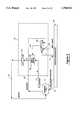
- FIG. 1illustrates a high level architectural block diagram of a processor 100 that includes a Bit Processing Unit 120 according to the present invention.
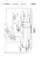
- FIG. 2shows a detailed block diagram of the Bit Processing Unit 120 according to the present invention.
- FIG. 3is a detailed block diagram of the logic used to implement a shift and rotate operation.
- FIG. 4is a detailed block diagram of the logic used to implement a clear bit-field operation.
- FIG. 5is a detailed block diagram of the logic used to implement an isolate bit-field operation.
- FIG. 6is a detailed block diagram of the logic used to implement an extract bit-field operation.
- FIG. 7is a detailed block diagram of the logic used to implement a load bit-field operation.
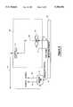
- FIG. 8is a detailed block diagram of the logic used to implement a compare bit-field operation.
- FIG. 9is a detailed block diagram of the logic used to implement a load literal field.
- FIG. 10illustrates the propagation delay of the critical path through the logic shown in FIG. 8.
- FIG. 1illustrates a high level architectural block diagram of a processor 100, constructed in accordance with the present invention. That is, FIG. 1 illustrates an environment for the present invention.
- Processor 100includes a register file 110, an instruction register 160, a Bit Processing Unit (BPU) 120, and Arithmetic Logic Unit (ALU) 130.
- BPU 120is adapted to execute complex logical operations in a single clock cycle by eliminating slow arithmetic operations and concentrating only on logical operations. Using BPU 120 as an alternative execution unit for non-arithmetic operations greatly enhances the performance of the processor.
- FIG. 1shows the relationship between ALU 130 and BPU 120.
- Register file 110has an A output 135, a B output 140 and an input 150. Both the A output 135 and the B output 140 are connected to ALU 130 and BPU 120.
- Input and Output from register file 110is controlled via one or more lines of control bus 116.
- information on control bus 116is generated based on the instruction currently being executed. This information can be generated during a decoding step or immediately prior to execution. As would be apparent to a person skilled in the relevant art, information on control bus 116 can be generated at other times.
- a line or busmay transfer a single bit of information or multiple bits of information depending on the specific context in which the line or bus is used (i.e., the specific designation used is not dispositive of the number of bits transferred).
- the outputs of BPU 120 and ALU 130are connected to multiplexer 140.
- One or more lines of a control bus 115are used to control the multiplexer 140 for forwarding results from BPU 120 and ALU 130 to the register file 110.
- Control bus 115also acts as an input to BPU 120 and ALU 130. Although only a single bus 115 is shown in FIG. 1, other control information may be used to control BPU 120, ALU 130 and multiplexer 140 as would be apparent to a person skilled in the relevant art.
- BPUhas three additional inputs originating from the instruction register 160. These inputs are based on three fields found in instructions stored in the instruction register 160: a LIT field 125, a RL field 126 and SHIFT COUNT field 127.
- LIT field 125represents a literal field in an instruction.
- the literal fieldis 18 bits in length.
- RL field 126is a single control bit within the instruction.
- the SHIFT COUNT field 127represents a zero to six bit field in the instruction.
- FIG. 2shows a detailed block diagram of BPU 120.
- the BPU 120supports register sizes of 48, 36 and 32 bits.
- register sizes48, 36 and 32 bits.
- a register size of 48is used for the remainder of this discussion to describe the operation of BPU 120.
- BPU 120includes a shift functional unit 210, a shift/rotate functional unit 220, and a merge function unit 230.
- the merge function unit 230includes digital logic (e.g., AND gates, OR gates, inverters, etc.) for performing a variety of boolean operations.
- BPU 120also includes a plurality of multiplexers for selecting data from the shift functional unit 210, the shift/rotate functional unit 220 and the merge function unit 230.
- the digital logic and mutliplexerswill be described in more detail below with reference to the specific operations of BPU 120.
- BPU 120also has two special purpose flags: a BPU -- Match -- Flag 260 (hereinafter match flag 260) and a BPU -- Equal -- Zero flag 270 (hereinafter zero flag 270).
- the match flag 260is updated only by a compare bit operation (described below).
- the zero flag 270is set when the current BPU operation result is equal to zero, and reset otherwise. It covers the entire width of the result word (as opposed to individual bits of the result word) and is updated on every BPU operation.
- the match flag 260 and the zero flag 270can be used for program execution control (e.g., branch to location XX if match flag is set).
- BPU 120is implemented to perform the following operations: (1) shift and rotate; (2) clear bit field; (3) isolate bit field; (4) extract bit field; (5) load bit field; (6) compare bit field; and (7) load literal field.
- operationsare discussed below with reference to a 48-bit word. However, the present invention contemplates any size word.
- FIG. 3shows exemplary logic required to perform the function of a shift and rotate.
- the logic to perform the shift and rotate functionincludes multiplexers 310 and 320 and a shift/rotate functional unit 220.
- This functionshifts or rotates an input word X number of bit positions toward the most significant bit (MSB).
- MSBmost significant bit
- Xis a number from 0 to (N-1) and N is the word size (e.g., 48 bits).
- Nis the word size (e.g., 48 bits).
- the operation specifiedis a shift, either 0's or 1's can be specified as the shift input into the least significant bit. This information is typically specified by the instruction (i.e., it is encoded in the instruction word).
- the shift output from the MSBis used as a shift input to the LSB. Bit position of the MSB depends on the word size.
- the input data word (i.e., X) used by this operationis from the A output 135 of the register file 110.
- the number of bit positions shifted or rotatedcan be specified in at least two different manners. First, it can be a 6-bit number specified directly in the instruction word. This is specified in the SHIFT COUNT field 127. Second, the number of bit positions shifted or rotated can be specified by a 6-bit number from a second register, e.g., the B output 140 of the register file 110. The control bit RL 126 specifies whether the SHIFT COUNT field 127 or the B output 135 is to be used.
- Both output ports of the register file 110will be used if a shift or rotate instruction chooses to use a 6-bit number from the B output 140 to supply the number of bit positions to be shifted/rotated. Only the least significant bits from the register are used in this case. The rest of the bits from the B output 140 are ignored.
- FIG. 4shows exemplary logic to perform the function of a clear bit-field.
- the logic to perform the clear bit-field functionincludes the shift functional unit 210, an AND gate 410, a NOT gate 420, and multiplexer 310. This is a single-operand operation which resets bits X: Y! to zero and leaves all other bits of the input word intact.
- Xis a number from 0 to (N-1), where N is the word size selected.
- Yis a number from 1 to 18.
- LIT 125is an 18-bit value from the current instruction with the high order bits padded with zeroes. LIT 125 is equal to Y.
- the SHIFT COUNT 127indicates how many bits LIT 125 should be shifted by shift functional unit 210. Shift functional unit 210 produces a 48-bit word having Y ones starting at bit X. This 48-bit word is input to NOT gate 420. The resulting 48-bit word having Y zeros starting at bit X. This 48-bit word is input to AND gate 410.
- the 48-bit input data word for this operationis from the A output 135 of the register file 110.
- the input data word from the A output 135in ANDed with the 48-bit word output from NOT gate 420.
- the resulting 48-bit wordhas bits X:Y! reset to zero while the other bits of the input data word remain intact.
- the resulting data wordis input to multiplexer 310.
- This data wordis then selected from multiplexer 310 and stored in the register file 110 via data line 150.
- Multiplexer 310is controlled via a set of control lines (not shown) that are generated based on the currently executing instruction word. Generation of this set of control lines should be readily apparent to one skilled in the relevant art.
- FIG. 5shows exemplary logic to perform the function of an isolate bit-field.
- the logic used to perform the isolate bit-field functionincludes the shift functional unit 210, AND gate 410 and multiplexer 310. This is a single-operand operation which resets to zero all bits of an input word except bits X:Y!.
- Xis a number from 0 to (N-1), where N is the word size selected.
- Yis a number from 1 to 18.
- tag bitsare carried from input to output unmodified.
- LIT 125is an 18-bit value from the current instruction with the high order bits padded with zeroes. LIT 125 is equal to Y.
- the SHIFT COUNT 127indicates how many bits LIT 125 should be shifted by shift functional unit 210. Shift functional unit 210 produces a 48-bit word having Y ones starting at bit X. This 48-bit word is input to AND gate 410.
- the 48-bit input data word for this operationis from the A output 135 of the register file 110.
- the input data word from the A output 135is ANDed with the 48-bit word output from shift functional unit 210.
- the resulting 48-bit wordhas all bits reset to zero except bits X:Y!.
- the resulting data wordis input to multiplexer 310. This data word is then selected from multiplexer 310 and stored in the register file 110 via data line 150.
- FIG. 6shows exemplary logic to perform the function of an extract bit-field.
- the logic to perform the extract bit-field functionincludes shift functional unit 210, shift/rotate functional unit 220, AND gate 410, and multiplexers 610 and 310. This is a single-operand operation that moves bits X:Y! of an input word down (Y-1):Y! and resets the rest of the bits to zero.
- Xis a number from 0 to (N-1), where N is the word size selected.
- Yis a number from 1 to 18.
- the 48-bit input data word for this operationis from the A output 135 of the register file 110.
- the data word from the A output 135is input to shift/rotate functional unit 220.
- the shift/rotate functional unit 220rotates the input word so that bit X becomes bit (Y-1).
- the shift output from the MSBis used as the shift input to the LSB.
- the number of bit positions rotatedcan be specified in at least two different manners. First, it can be a 6-bit number specified directly in the instruction word stored in instruction register 160. This is specified in the SHIFT COUNT field 127. Second, the number of bit positions shifted or rotated can be specified by a 6-bit number from a second register, e.g., the B output 140 of the register file 110. Note that only the least significant bits from the B output 140 of register file 110 are used as an input to shift/register functional unit 220. The rest of the bits from the B output 140 are ignored.
- the control bit RL 126specifies whether the SHIFT COUNT field 127 or the B output 135 is to be used. Both the SHIFT COUNT field 127 and the B output 140 are input to multiplexer 610. Based on the value of the RL field 126, one of these two inputs is selected from multiplexer 610 and used as an input to shift/rotate functional unit 220 via line 630. The 48-bit word produced by shift/rotate functional unit 220 is input to AND gate 410 via line 640.
- LIT 125is an 18-bit value from the current instruction with the high order bits padded with zeroes. LIT 125 is equal to Y.
- the SHIFT COUNT 127indicates how many bits LIT 125 should be shifted by shift functional unit 210. Shift functional unit 210 produces a 48-bit word having Y ones starting at bit X. This 48-bit word is input to AND gate 410 via line 620.
- the 48-bit word on line 620is ANDed with the 48-bit word on line 640.
- the resulting 48-bit data wordis input to multiplexer 310 via line 650. This data word is then selected from multiplexer 310 and stored in the register file 110 via data line 150.
- FIG. 7shows exemplary logic to perform the function of a load bit-field.
- the logicincludes shift functional unit 210, shift/rotate functional unit 220, AND gates 410 and 710, OR gate 720 and multiplexers 610 and 310.
- the load bit-fieldis a two-operand operation that performs the reverse of the extract bit-field function described above. It replaces bits X:Y! of a first input word with the contents of bit field (Y-1):Y! of the second input word. The other bits of the resulting word are copied directly from the first input word.
- Xis a number from 0 to (N-1), where N is the word size selected.
- Yis a number from 1 to 18.
- tag bitsare carried from input to output unmodified.
- the first 48-bit input word for this operationis from the A output 135 of the register file 110.
- the data word from the A output 135is input to shift/rotate functional unit 220.
- the shift/rotate functional unit 220rotates the input word so that bit X becomes bit (Y-1).
- the shift output from the MSBis used as the shift input to the LSB.
- the number of bit positions rotatedcan once again be specified in at least two different manners. First, it can be a 6-bit number specified directly in the instruction word stored in instruction register 160. This is specified in the
- the number of bit positions shifted or rotatedcan be specified by a 6-bit number from a second register, e.g., the B output 140 of the register file 110. Note that only the least significant bits from the B output 140 of register file 110 are used as an input to shift/register functional unit 220. The rest of the bits from the B output 140 are ignored.
- the control bit RL 126specifies whether the SHIFT COUNT field 127 or the B output 135 is to be used. Both the SHIFT COUNT field 127 and the B output 140 are input to multiplexer 610. Based on the value of the RL field 126, one of these two inputs are selected from multiplexer 610 and used as an input to shift/rotate functional unit 220 via line 630. The 48-bit word produced by shift/rotate functional unit 220 is input to AND gate 410 via line 640.
- LIT 125is an 18-bit value from the current instruction with the high order bits padded with zeroes. LIT 125 is equal to Y.
- the SHIFT COUNT 127indicates how many bits LIT 125 should be shifted by shift functional unit 210. Shift functional unit 210 produces a 48-bit word having Y ones starting at bit X. This 48-bit word is input to AND gate 410 and AND gate 710 via line 620.
- the 48-bit word on line 620is ANDed with the 48-bit word on line 640.
- the resulting 48-bit data wordis input to OR gate 720 via line 650.
- the 48-bit word on line 620is also ANDed with the B output 140 of register file 110.
- the outputs of AND gate 410 and AND gate 710are input to OR gate 720 via line 650 and line 730, respectively.
- the 48-bit word on line 650is ORed with the 48-bit word on line 730.
- the output of OR gate 720is input to multiplexer 310 via line 740. This data word is then selected from multiplexer 310 and stored in the register file 110 via data line 150.
- the load bit-field operationis performed by shifting input word A and LIT, which contains a selection mask, to the target bit field position and then setting each bit of the output word equal to the corresponding bit of either A or B depending on whether the corresponding mask bit is a one or a zero.
- FIG. 8shows exemplary logic to perform the function of a compare bit-field.
- the logic used to perform the compare bit-field functionincludes shift functional unit 210, shift/rotate functional unit 220, AND gates 410 and 710, XOR gate 840, OR gate 850, and multiplexers 610 and 830.
- the compare bit-field operationdoes not generate a full size result word. It merely sets or resets the BPU -- Match flag 260. Similar to other operations performed by BPU 120, the compare bit-field operation also updates BPU -- Equal -- Zero flag 270. Since no result word is defined in this case, the content of BPU -- Equal -- Zero flag 170 becomes undefined after a compare bit-field operation.
- the first mode of operationcompares bits X:Y! of an input word to bits (Y-1):Y! of a second input word.
- the BPU -- Match flag 260is set to true when the contents of the two bit fields are exactly the same. Otherwise, the BPU -- Match flag is cleared to zero.
- Xis a number from 0 to (N-1), where N is the word size defined by the architecture 100.
- Yis a number from 1 to 18.
- the second mode of operation of the compare bit-fieldcompares bits X:Y! of the first input word with an 8-bit number from the current instruction word.
- Xis a number from 0 to (N-1), where N is the word size defined by the architecture 100.
- Yis a number from 1 to 18. If Y is specified to be more than 8 bits wide, the 8-bit number from the instruction word is padded with zeros on the high order bit before the comparison is executed.
- the BPU -- Match flag 260is set or cleared accordingly.
- the BPU -- Match flag 260retains its value until the next compare bit-field operation.
- the BPU -- Match flag 260is automatically saved and restored during a hardware interrupt.
- the compare bit-field operationis done by performing an extract bit-field operation on the first input word, followed by a comparison function to compare the result of the extract bit-field operation with either the second input word or the 8-bit number from the current instruction word stored in the instruction register 160.
- the logic for the compare bit-field operationis described in detail below.
- the first 48-bit input word for this operationis from the A output 135 of the register file 110.
- the data word from the A output 135is input to shift/rotate functional unit 220.
- the shift/rotate functional unit 220rotates the input word so that bit X becomes bit (Y-1).
- the shift output from the MSBis used as the shift input to the LSB.
- the number of bit positions rotatedcan once again be specified in two different manners. First, it can be a 6-bit number specified directly in the instruction word stored in instruction register 160. This is specified in the SHIFT COUNT field 127. Second, the number of bit positions rotated can be specified by a 6-bit number from a second register, i.e., the B output 140 of the register file 110. Note, once again, that only the least significant bits from the B output 140 of register file 110 are used as an input to shift/register functional unit 220. The rest of the bits from the B output 140 are ignored.
- the control bit RL 126specifies whether the SHIFT COUNT field 127 or the B output 140 is to be used. Both the SHIFT COUNT field 127 and the B output 140 are input to multiplexer 610. Based on the value of the RL field 126, one of these two inputs are selected from multiplexer 610 and used as a control input to shift/rotate functional unit 220 via line 630. The 48-bit word produced by shift/rotate functional unit 220 is input to AND gate 410 via line 640.
- LIT 125is an 18-bit value from the current instruction word with the high order bits padded with zeroes. LIT 125 is equal to Y.
- the SHIFT COUNT 127indicates how many bits LIT 125 should be shifted by shift functional unit 210. Shift functional unit 210 produces a 48-bit word having Y number of ones starting at bit X. This 48-bit word is input to AND gate 410 and AND gate 710 via line 620.
- the 48-bit word on line 620is ANDed with the 48-bit word on line 640 (produced by shift/rotate functional unit 220).
- the resulting 48-bit data wordis input to multiplexer 830 via line 860.
- an 8 bit number 810 from the current instruction word (i.e., the instruction word currently being executed) in instruction register 160is provided to multiplexer 830.
- Multiplexer 830is controlled by a SEL field 820 in the instruction stored in instruction register 160.
- the SEL field 820determines whether BPU 120 operates under the first mode or the second mode of operation.
- the output from multiplexer 830is provided to XOR gate 840 via line 870.
- the 48-bit word on line 620is ANDed with the B output 140 of register file 110.
- the outputs of AND gate 710is input to XOR gate 840 via line 880.
- the input on line 870is XORed with the input on line 880 to produce a value on bus 890.
- the value on bus 890is input to OR gate 850.
- OR gate 850performs a logical OR operation on all bits of the input word on bus 890.
- OR gate 850is replaced with a NOR gate (not shown). Thus, in the alternate embodiment, a logical one at the output of the NOR gate indicates a match.
- the present inventionperforms all the bit manipulation operations in a single clock cycle.
- the compare bit-field operationas describe above, has the longest propagation delay relative to the other bit manipulation operations performed by BPU 120. As such, an brief explanation of the propagation delay through the critical path of the logic shown in FIG. 8 is provided below.
- FIG. 10illustrates the propagation delay of the critical path through the logic shown in FIG. 8.
- a single clock cycleis 20 nanoseconds (ns) and a compare bit-field operation takes 14.8 ns to complete.
- the critical pathis a path within the logic that requires the longest propagation delay in order to complete the execution of an instruction.
- the delays associated with each of the hardware units shown in FIG. 8are as follows.
- the instruction registerhas a propagation delay of 1 ns, i.e, it takes 1 ns to place data on input/output control line 116, RL line 126, SHIFT COUNT 127, LIT 125, etc.
- Register file 110has a propagation delay of 6 ns, i.e., it takes 6 ns to place data on output A 135 and/or output B 140.
- Shift functional unit 210 and Shift/Rotate functional unit 220have a propagation delay of 3 ns.
- AND gate 410 and AND gate 710have a propagation delay of 0.6 ns.
- Multiplexer 610has a propagation delay of 1 ns and multiplexer 830 has a propagation delay of 0.5 ns.
- XOR gatehas a propagation delay of 0.7 ns and OR gate 850 has a propagation delay of 3 ns.
- the critical path to complete the compare bit-field operationincludes instruction register 160, register file 110, shift/rotate functional unit 220, AND gate 410, multiplexer 830, XOR gate 840, and 0R gate 850.
- datais placed on the input/output control line 116 after 1 ns.
- register file 110places data on output A 135 and output B 140. This is shown at reference number 1030.
- Shift/rotate functional unitrequires a propagation delay of 3 ns.
- Datais thus placed on line 640 after a total of 10 ns, as shown at reference number 1050.
- Datais then place on line 870 after a propagation delay of 0.5 ns for multiplexer 830. This is shown at reference numbers 1060 and 1070, respectively.
- Line 870is one of two inputs to XOR gate 840.
- the second input to XOR gate 840is line 880.
- the propagation delay associated with line 880is also shown in FIG. 10 (i.e., line 140, line 620, and AND gate 710).
- line 880is not part of the critical path since data is available on this line after 7.6ns, as shown at reference number 1040; whereas data is available on line 870 after a larger propagation delay of 11.1 ns.
- datais available on line 890 after an additional propagation delay of 0.7 ns associated with XOR gate 840.
- OR gate 850has an associated propagation delay of 3 ns. Accordingly, data is available on line 895 after a total propagation delay of 14.8 ns, as shown at reference number 1090.
- the compare bit-field operationhas an execution time under one clock cycle (i.e., under 20 ns). It should be readily apparent to those skilled in the art based on this example, that the other operations described herein also have an execution time of under one clock cycle.
- FIG. 9shows exemplary logic to perform the function of a load LIT shifted.
- the logic used to perform this functionincludes shift functional unit 210 and multiplexer 310. This operation assigns a shifted 18-bit LIT value 125 to a register.
- the shift functioncan position the 18-bit LIT value 125 to anywhere within the 48-bit word. Bits outside the target 18-bit field are cleared to zero.
- the SHIFT COUNT 127indicates how many bits LIT 125 should be shifted by shift functional unit 210.
- Shift functional unit 210produces a 48-bit word having the LIT value 125 positioned within a word as indicated by SHIFT COUNT 125.
- the resulting data wordis input to multiplexer 310. This data word is then selected from multiplexer 310 and stored in the register file 110 via data line 150.
- BPU 120The majority of the operations performed by BPU 120 utilize the same gates. For example, the same shift register is used in all operations requiring shifting. This resource sharing of logic enables BPU 120 to be implemented using relatively few gates. Inspection of typical microcode routines indicate that 60-70 percent of the processor time is used to perform bit manipulation operations. Consequently, BPU 120 is no larger than ALU 130, but produces on average three times the performance over conventional microprocessors.
- BPU 120allows a microprocessor to schedule the execution of instructions in a more efficient manner.
- the microprocessordoes not need to stall while more complex, time consuming arithmetic operations are executed.
- the present inventionallows logical operations to be executed in parallel or out-of-order relative to arithmetic operations.
- the present inventionprovides a microprocessor system that accommodates or otherwise avoids stalling between an arithmetic operation and a logical operation.
Landscapes
- Engineering & Computer Science (AREA)
- Theoretical Computer Science (AREA)
- Physics & Mathematics (AREA)
- General Physics & Mathematics (AREA)
- Software Systems (AREA)
- General Engineering & Computer Science (AREA)
- Computational Mathematics (AREA)
- Mathematical Analysis (AREA)
- Mathematical Optimization (AREA)
- Pure & Applied Mathematics (AREA)
- Mathematical Physics (AREA)
- Computing Systems (AREA)
- Executing Machine-Instructions (AREA)
Abstract
Description
Claims (41)
Priority Applications (1)
| Application Number | Priority Date | Filing Date | Title |
|---|---|---|---|
| US08/635,541US5704052A (en) | 1994-11-06 | 1996-04-22 | Bit processing unit for performing complex logical operations within a single clock cycle |
Applications Claiming Priority (2)
| Application Number | Priority Date | Filing Date | Title |
|---|---|---|---|
| US35209294A | 1994-11-06 | 1994-11-06 | |
| US08/635,541US5704052A (en) | 1994-11-06 | 1996-04-22 | Bit processing unit for performing complex logical operations within a single clock cycle |
Related Parent Applications (1)
| Application Number | Title | Priority Date | Filing Date |
|---|---|---|---|
| US35209294AContinuation | 1994-11-06 | 1994-11-06 |
Publications (1)
| Publication Number | Publication Date |
|---|---|
| US5704052Atrue US5704052A (en) | 1997-12-30 |
Family
ID=23383766
Family Applications (1)
| Application Number | Title | Priority Date | Filing Date |
|---|---|---|---|
| US08/635,541Expired - LifetimeUS5704052A (en) | 1994-11-06 | 1996-04-22 | Bit processing unit for performing complex logical operations within a single clock cycle |
Country Status (1)
| Country | Link |
|---|---|
| US (1) | US5704052A (en) |
Cited By (21)
| Publication number | Priority date | Publication date | Assignee | Title |
|---|---|---|---|---|
| US5991520A (en)* | 1996-02-02 | 1999-11-23 | Sony Corporation | Application programming interface for managing and automating data transfer operations between applications over a bus structure |
| US6094718A (en)* | 1997-02-26 | 2000-07-25 | Matsushita Electric Works, Ltd. | Programmable controller with a BPU that executes first-class instructions, a CPU that executes second-class instructions, and a skip instruction processing section that skips the current instruction without transferring control right to CPU |
| WO2000058828A1 (en)* | 1999-03-26 | 2000-10-05 | Microchip Technology Incorporated | Microcontroller instruction set |
| US6167471A (en)* | 1998-10-14 | 2000-12-26 | Sony Corporation | Method of and apparatus for dispatching a processing element to a program location based on channel number of received data |
| US6266727B1 (en) | 1996-03-07 | 2001-07-24 | Sony Corporation | Isochronous data pipe for managing and manipulating a high-speed stream of isochronous data flowing between an application and a bus structure |
| US6292844B1 (en) | 1998-02-12 | 2001-09-18 | Sony Corporation | Media storage device with embedded data filter for dynamically processing data during read and write operations |
| US6385717B1 (en)* | 1998-08-17 | 2002-05-07 | U.S. Philips Corporation | Programmable 1-bit data processing arrangement |
| US6519268B1 (en) | 1996-03-07 | 2003-02-11 | Sony Corporation | Asynchronous data pipe for automatically managing asynchronous data transfers between an application and a bus structure |
| US6523108B1 (en) | 1999-11-23 | 2003-02-18 | Sony Corporation | Method of and apparatus for extracting a string of bits from a binary bit string and depositing a string of bits onto a binary bit string |
| US6631435B1 (en) | 1996-02-02 | 2003-10-07 | Sony Corporation | Application programming interface for data transfer and bus management over a bus structure |
| US6721859B1 (en) | 1999-10-21 | 2004-04-13 | Sony Corporation | Multi-protocol media storage device implementing protocols optimized for storing and retrieving both asynchronous and isochronous data |
| US6859846B2 (en) | 1999-05-12 | 2005-02-22 | Sony Corporation | Method of distributed recording whereby the need to transition to a second recording device from a first recording device is broadcast by the first recording device |
| US6904475B1 (en) | 2000-11-06 | 2005-06-07 | Sony Corporation | Programmable first-in first-out (FIFO) memory buffer for concurrent data stream handling |
| US6993646B2 (en) | 1999-05-12 | 2006-01-31 | Sony Corporation | Automatically configuring storage array including plurality of media storage devices for storing and providing data within a network of devices |
| US7124292B2 (en) | 2001-05-21 | 2006-10-17 | Sony Corporation | Automatically configuring storage array including a plurality of media storage devices for storing and providing data within a network of devices |
| US20080077643A1 (en)* | 2006-09-26 | 2008-03-27 | Oki Electric Industry Co., Ltd. | Bit field operation circuit |
| US7577782B2 (en) | 1996-02-02 | 2009-08-18 | Sony Corporation | Application programming interface for data transfer and bus management over a bus structure |
| US7720821B1 (en) | 2000-06-30 | 2010-05-18 | Sony Corporation | Method of and apparatus for writing and reading time sensitive data within a storage device |
| US20110153997A1 (en)* | 2009-12-22 | 2011-06-23 | Maxim Loktyukhin | Bit Range Isolation Instructions, Methods, and Apparatus |
| EP2691850A4 (en)* | 2011-03-30 | 2015-06-03 | Freescale Semiconductor Inc | Integrated circuit device and methods of performing bit manipulation therefor |
| US9135008B2 (en) | 2009-09-24 | 2015-09-15 | Freescale Semiconductor, Inc. | Device and method for performing conditional bitwise set/clear/toggle manipulations in a general purpose register |
Citations (15)
| Publication number | Priority date | Publication date | Assignee | Title |
|---|---|---|---|---|
| US3982229A (en)* | 1975-01-08 | 1976-09-21 | Bell Telephone Laboratories, Incorporated | Combinational logic arrangement |
| US4085447A (en)* | 1976-09-07 | 1978-04-18 | Sperry Rand Corporation | Right justified mask transfer apparatus |
| US4139899A (en)* | 1976-10-18 | 1979-02-13 | Burroughs Corporation | Shift network having a mask generator and a rotator |
| US4467444A (en)* | 1980-08-01 | 1984-08-21 | Advanced Micro Devices, Inc. | Processor unit for microcomputer systems |
| US4569016A (en)* | 1983-06-30 | 1986-02-04 | International Business Machines Corporation | Mechanism for implementing one machine cycle executable mask and rotate instructions in a primitive instruction set computing system |
| US4903228A (en)* | 1988-11-09 | 1990-02-20 | International Business Machines Corporation | Single cycle merge/logic unit |
| US5005118A (en)* | 1987-04-10 | 1991-04-02 | Tandem Computers Incorporated | Method and apparatus for modifying micro-instructions using a macro-instruction pipeline |
| US5123108A (en)* | 1989-09-11 | 1992-06-16 | Wang Laboratories, Inc. | Improved cpu pipeline having register file bypass and working register bypass on update/access address compare |
| US5175863A (en)* | 1989-10-23 | 1992-12-29 | International Business Machines Corporation | Signal data processing system having independently, simultaneously operable alu and macu |
| US5177679A (en)* | 1988-12-29 | 1993-01-05 | Advanced Micro Devices Inc. | Picoprocessor |
| US5197138A (en)* | 1989-12-26 | 1993-03-23 | Digital Equipment Corporation | Reporting delayed coprocessor exceptions to code threads having caused the exceptions by saving and restoring exception state during code thread switching |
| US5197135A (en)* | 1990-06-26 | 1993-03-23 | International Business Machines Corporation | Memory management for scalable compound instruction set machines with in-memory compounding |
| US5201056A (en)* | 1990-05-02 | 1993-04-06 | Motorola, Inc. | RISC microprocessor architecture with multi-bit tag extended instructions for selectively attaching tag from either instruction or input data to arithmetic operation output |
| US5210835A (en)* | 1986-08-27 | 1993-05-11 | Ken Sakamura | Data processing system having apparatus for increasing the execution speed of bit field instructions |
| US5287532A (en)* | 1989-11-14 | 1994-02-15 | Amt (Holdings) Limited | Processor elements having multi-byte structure shift register for shifting data either byte wise or bit wise with single-bit output formed at bit positions thereof spaced by one byte |
- 1996
- 1996-04-22USUS08/635,541patent/US5704052A/ennot_activeExpired - Lifetime
Patent Citations (15)
| Publication number | Priority date | Publication date | Assignee | Title |
|---|---|---|---|---|
| US3982229A (en)* | 1975-01-08 | 1976-09-21 | Bell Telephone Laboratories, Incorporated | Combinational logic arrangement |
| US4085447A (en)* | 1976-09-07 | 1978-04-18 | Sperry Rand Corporation | Right justified mask transfer apparatus |
| US4139899A (en)* | 1976-10-18 | 1979-02-13 | Burroughs Corporation | Shift network having a mask generator and a rotator |
| US4467444A (en)* | 1980-08-01 | 1984-08-21 | Advanced Micro Devices, Inc. | Processor unit for microcomputer systems |
| US4569016A (en)* | 1983-06-30 | 1986-02-04 | International Business Machines Corporation | Mechanism for implementing one machine cycle executable mask and rotate instructions in a primitive instruction set computing system |
| US5210835A (en)* | 1986-08-27 | 1993-05-11 | Ken Sakamura | Data processing system having apparatus for increasing the execution speed of bit field instructions |
| US5005118A (en)* | 1987-04-10 | 1991-04-02 | Tandem Computers Incorporated | Method and apparatus for modifying micro-instructions using a macro-instruction pipeline |
| US4903228A (en)* | 1988-11-09 | 1990-02-20 | International Business Machines Corporation | Single cycle merge/logic unit |
| US5177679A (en)* | 1988-12-29 | 1993-01-05 | Advanced Micro Devices Inc. | Picoprocessor |
| US5123108A (en)* | 1989-09-11 | 1992-06-16 | Wang Laboratories, Inc. | Improved cpu pipeline having register file bypass and working register bypass on update/access address compare |
| US5175863A (en)* | 1989-10-23 | 1992-12-29 | International Business Machines Corporation | Signal data processing system having independently, simultaneously operable alu and macu |
| US5287532A (en)* | 1989-11-14 | 1994-02-15 | Amt (Holdings) Limited | Processor elements having multi-byte structure shift register for shifting data either byte wise or bit wise with single-bit output formed at bit positions thereof spaced by one byte |
| US5197138A (en)* | 1989-12-26 | 1993-03-23 | Digital Equipment Corporation | Reporting delayed coprocessor exceptions to code threads having caused the exceptions by saving and restoring exception state during code thread switching |
| US5201056A (en)* | 1990-05-02 | 1993-04-06 | Motorola, Inc. | RISC microprocessor architecture with multi-bit tag extended instructions for selectively attaching tag from either instruction or input data to arithmetic operation output |
| US5197135A (en)* | 1990-06-26 | 1993-03-23 | International Business Machines Corporation | Memory management for scalable compound instruction set machines with in-memory compounding |
Non-Patent Citations (4)
| Title |
|---|
| G.B. Steven, et al., "HARP: A Parallel Pipelined RISC Processor," Microprocessors and Microsystems, vol. 13, No. 9, Nov. 1989, pp. 579-587. |
| G.B. Steven, et al., HARP: A Parallel Pipelined RISC Processor, Microprocessors and Microsystems, vol. 13, No. 9, Nov. 1989, pp. 579 587.* |
| R.G. Adams, et al., "Utilising Low Level Parallelism in General Purpose Code: The HARP Project," Microprocessing and Microprogramming, vol. 29, No. 3, Oct. 1990, pp. 137-149. |
| R.G. Adams, et al., Utilising Low Level Parallelism in General Purpose Code: The HARP Project, Microprocessing and Microprogramming, vol. 29, No. 3, Oct. 1990, pp. 137 149.* |
Cited By (43)
| Publication number | Priority date | Publication date | Assignee | Title |
|---|---|---|---|---|
| US6243783B1 (en) | 1996-02-02 | 2001-06-05 | Sony Corporation | Application programming interface for managing and automating data transfer operations between applications over a bus structure |
| US7577782B2 (en) | 1996-02-02 | 2009-08-18 | Sony Corporation | Application programming interface for data transfer and bus management over a bus structure |
| US5991520A (en)* | 1996-02-02 | 1999-11-23 | Sony Corporation | Application programming interface for managing and automating data transfer operations between applications over a bus structure |
| US6631435B1 (en) | 1996-02-02 | 2003-10-07 | Sony Corporation | Application programming interface for data transfer and bus management over a bus structure |
| US7103700B2 (en) | 1996-03-07 | 2006-09-05 | Sony Corporation | Method of and apparatus for controlling bidirectional streams of isochronous data flowing between an application and a bus structure |
| US6266727B1 (en) | 1996-03-07 | 2001-07-24 | Sony Corporation | Isochronous data pipe for managing and manipulating a high-speed stream of isochronous data flowing between an application and a bus structure |
| US6519268B1 (en) | 1996-03-07 | 2003-02-11 | Sony Corporation | Asynchronous data pipe for automatically managing asynchronous data transfers between an application and a bus structure |
| US7944952B2 (en) | 1996-03-07 | 2011-05-17 | Sony Corporation | Asynchronous data pipe for automatically managing asynchronous data transfers between an application and a bus structure |
| US6587910B2 (en) | 1996-03-07 | 2003-07-01 | Sony Corporation | Isochronous data pipe for managing and manipulating a high-speed stream of isochronous data flowing between an application and a bus structure |
| US20090268760A1 (en)* | 1996-03-07 | 2009-10-29 | Sony Corporation | Asynchronous data pipe for automatically managing asynchronous data transfers between an application and a bus structure |
| US7567590B2 (en) | 1996-03-07 | 2009-07-28 | Sony Corporation | Asynchronous data pipe for automatically managing asynchronous data transfers between an application and a bus structure |
| US7145921B2 (en) | 1996-03-07 | 2006-12-05 | Sony Corporation | Asynchronous data pipe for automatically managing asynchronous data transfers between an application and a bus structure |
| US7287113B2 (en) | 1996-03-07 | 2007-10-23 | Sony Corporation | Method of and apparatus for controlling bidirectional streams of isochronous data flowing between an application and a bus structure |
| US6094718A (en)* | 1997-02-26 | 2000-07-25 | Matsushita Electric Works, Ltd. | Programmable controller with a BPU that executes first-class instructions, a CPU that executes second-class instructions, and a skip instruction processing section that skips the current instruction without transferring control right to CPU |
| US6292844B1 (en) | 1998-02-12 | 2001-09-18 | Sony Corporation | Media storage device with embedded data filter for dynamically processing data during read and write operations |
| US6385717B1 (en)* | 1998-08-17 | 2002-05-07 | U.S. Philips Corporation | Programmable 1-bit data processing arrangement |
| US6757760B1 (en) | 1998-10-14 | 2004-06-29 | Sony Corporation | Method of and apparatus for dispatching a processing element to a program location based on channel number of received data |
| US6167471A (en)* | 1998-10-14 | 2000-12-26 | Sony Corporation | Method of and apparatus for dispatching a processing element to a program location based on channel number of received data |
| US6708268B1 (en) | 1999-03-26 | 2004-03-16 | Microchip Technology Incorporated | Microcontroller instruction set |
| US20040158692A1 (en)* | 1999-03-26 | 2004-08-12 | Microchip Technology Incorporated | Microcontroller instruction set |
| US7203818B2 (en) | 1999-03-26 | 2007-04-10 | Microchip Technology Inc. | Microcontroller instruction set |
| US7206924B2 (en) | 1999-03-26 | 2007-04-17 | Microchip Technology Inc. | Microcontroller instruction set |
| US20040177211A1 (en)* | 1999-03-26 | 2004-09-09 | Microchip Technology Incorporated | Microcontroller instruction set |
| WO2000058828A1 (en)* | 1999-03-26 | 2000-10-05 | Microchip Technology Incorporated | Microcontroller instruction set |
| US7254702B2 (en) | 1999-05-12 | 2007-08-07 | Sony Corporation | Method of distributed recording whereby the need to transition to a second recording device from a first recording device is broadcast by the first recording device |
| US6859846B2 (en) | 1999-05-12 | 2005-02-22 | Sony Corporation | Method of distributed recording whereby the need to transition to a second recording device from a first recording device is broadcast by the first recording device |
| US6993646B2 (en) | 1999-05-12 | 2006-01-31 | Sony Corporation | Automatically configuring storage array including plurality of media storage devices for storing and providing data within a network of devices |
| US6721859B1 (en) | 1999-10-21 | 2004-04-13 | Sony Corporation | Multi-protocol media storage device implementing protocols optimized for storing and retrieving both asynchronous and isochronous data |
| US6523108B1 (en) | 1999-11-23 | 2003-02-18 | Sony Corporation | Method of and apparatus for extracting a string of bits from a binary bit string and depositing a string of bits onto a binary bit string |
| US7720821B1 (en) | 2000-06-30 | 2010-05-18 | Sony Corporation | Method of and apparatus for writing and reading time sensitive data within a storage device |
| US6904475B1 (en) | 2000-11-06 | 2005-06-07 | Sony Corporation | Programmable first-in first-out (FIFO) memory buffer for concurrent data stream handling |
| US7124292B2 (en) | 2001-05-21 | 2006-10-17 | Sony Corporation | Automatically configuring storage array including a plurality of media storage devices for storing and providing data within a network of devices |
| US20080077643A1 (en)* | 2006-09-26 | 2008-03-27 | Oki Electric Industry Co., Ltd. | Bit field operation circuit |
| US7949697B2 (en)* | 2006-09-26 | 2011-05-24 | Oki Semiconductor Co., Ltd. | Bit field operation circuit |
| US9135008B2 (en) | 2009-09-24 | 2015-09-15 | Freescale Semiconductor, Inc. | Device and method for performing conditional bitwise set/clear/toggle manipulations in a general purpose register |
| US9003170B2 (en) | 2009-12-22 | 2015-04-07 | Intel Corporation | Bit range isolation instructions, methods, and apparatus |
| US20110153997A1 (en)* | 2009-12-22 | 2011-06-23 | Maxim Loktyukhin | Bit Range Isolation Instructions, Methods, and Apparatus |
| US10372455B2 (en) | 2009-12-22 | 2019-08-06 | Intel Corporation | Hand held device to perform a bit range isolation instruction |
| US10579380B2 (en) | 2009-12-22 | 2020-03-03 | Intel Corporation | System-on-chip (SoC) to perform a bit range isolation instruction |
| US10579379B2 (en) | 2009-12-22 | 2020-03-03 | Intel Corporation | Processor to perform a bit range isolation instruction |
| US10656947B2 (en) | 2009-12-22 | 2020-05-19 | Intel Corporation | Processor to perform a bit range isolation instruction |
| EP2691850A4 (en)* | 2011-03-30 | 2015-06-03 | Freescale Semiconductor Inc | Integrated circuit device and methods of performing bit manipulation therefor |
| US9639362B2 (en) | 2011-03-30 | 2017-05-02 | Nxp Usa, Inc. | Integrated circuit device and methods of performing bit manipulation therefor |
Similar Documents
| Publication | Publication Date | Title |
|---|---|---|
| US5704052A (en) | Bit processing unit for performing complex logical operations within a single clock cycle | |
| US5996057A (en) | Data processing system and method of permutation with replication within a vector register file | |
| US6334176B1 (en) | Method and apparatus for generating an alignment control vector | |
| US4748585A (en) | Processor utilizing reconfigurable process segments to accomodate data word length | |
| US6151669A (en) | Methods and apparatus for efficient control of floating-point status register | |
| EP2241968B1 (en) | System with wide operand architecture, and method | |
| US6295599B1 (en) | System and method for providing a wide operand architecture | |
| US5379240A (en) | Shifter/rotator with preconditioned data | |
| KR100319353B1 (en) | An arithmetic logic unit having a plurality of independent sections and register store result indication bits from all sections, | |
| US5710902A (en) | Instruction dependency chain indentifier | |
| US5675758A (en) | Processor having primary integer execution unit and supplemental integer execution unit for performing out-of-order add and move operations | |
| US4903228A (en) | Single cycle merge/logic unit | |
| JPH087084A (en) | Three-input arithmetic and logic unit for formation of sum of first boolean combination of first, second and third inputs plus second boolean combination of first, second and third inputs | |
| US7546442B1 (en) | Fixed length memory to memory arithmetic and architecture for direct memory access using fixed length instructions | |
| EP2309382B1 (en) | System with wide operand architecture and method | |
| US5815420A (en) | Microprocessor arithmetic logic unit using multiple number representations | |
| US6308189B1 (en) | Apparatus for partial logical shifts and method therefor | |
| US20030037085A1 (en) | Field processing unit | |
| KR100735944B1 (en) | Method and computer program for single instruction multiple data management | |
| US6499046B1 (en) | Saturation detection apparatus and method therefor | |
| US5974531A (en) | Methods and systems of stack renaming for superscalar stack-based data processors | |
| US5479620A (en) | Control unit modifying micro instructions for one cycle execution | |
| US5446909A (en) | Binary multiplication implemented by existing hardware with minor modifications to sequentially designate bits of the operand | |
| JPH05274143A (en) | Composite condition processing system | |
| CN112148373A (en) | Apparatus, method and system for vector processor architecture with identical circuit block arrays |
Legal Events
| Date | Code | Title | Description |
|---|---|---|---|
| STCF | Information on status: patent grant | Free format text:PATENTED CASE | |
| FPAY | Fee payment | Year of fee payment:4 | |
| FPAY | Fee payment | Year of fee payment:8 | |
| FPAY | Fee payment | Year of fee payment:12 | |
| REMI | Maintenance fee reminder mailed | ||
| AS | Assignment | Owner name:UNISYS CORPORATION, PENNSYLVANIA Free format text:RELEASE BY SECURED PARTY;ASSIGNOR:CITIBANK, N.A.;REEL/FRAME:023312/0044 Effective date:20090601 Owner name:UNISYS HOLDING CORPORATION, DELAWARE Free format text:RELEASE BY SECURED PARTY;ASSIGNOR:CITIBANK, N.A.;REEL/FRAME:023312/0044 Effective date:20090601 Owner name:UNISYS CORPORATION,PENNSYLVANIA Free format text:RELEASE BY SECURED PARTY;ASSIGNOR:CITIBANK, N.A.;REEL/FRAME:023312/0044 Effective date:20090601 Owner name:UNISYS HOLDING CORPORATION,DELAWARE Free format text:RELEASE BY SECURED PARTY;ASSIGNOR:CITIBANK, N.A.;REEL/FRAME:023312/0044 Effective date:20090601 | |
| AS | Assignment | Owner name:UNISYS CORPORATION, PENNSYLVANIA Free format text:RELEASE BY SECURED PARTY;ASSIGNOR:CITIBANK, N.A.;REEL/FRAME:023263/0631 Effective date:20090601 Owner name:UNISYS HOLDING CORPORATION, DELAWARE Free format text:RELEASE BY SECURED PARTY;ASSIGNOR:CITIBANK, N.A.;REEL/FRAME:023263/0631 Effective date:20090601 Owner name:UNISYS CORPORATION,PENNSYLVANIA Free format text:RELEASE BY SECURED PARTY;ASSIGNOR:CITIBANK, N.A.;REEL/FRAME:023263/0631 Effective date:20090601 Owner name:UNISYS HOLDING CORPORATION,DELAWARE Free format text:RELEASE BY SECURED PARTY;ASSIGNOR:CITIBANK, N.A.;REEL/FRAME:023263/0631 Effective date:20090601 | |
| AS | Assignment | Owner name:DEUTSCHE BANK TRUST COMPANY AMERICAS, AS COLLATERA Free format text:PATENT SECURITY AGREEMENT (PRIORITY LIEN);ASSIGNOR:UNISYS CORPORATION;REEL/FRAME:023355/0001 Effective date:20090731 | |
| AS | Assignment | Owner name:DEUTSCHE BANK TRUST COMPANY AMERICAS, AS COLLATERA Free format text:PATENT SECURITY AGREEMENT (JUNIOR LIEN);ASSIGNOR:UNISYS CORPORATION;REEL/FRAME:023364/0098 Effective date:20090731 | |
| AS | Assignment | Owner name:GENERAL ELECTRIC CAPITAL CORPORATION, AS AGENT, IL Free format text:SECURITY AGREEMENT;ASSIGNOR:UNISYS CORPORATION;REEL/FRAME:026509/0001 Effective date:20110623 | |
| AS | Assignment | Owner name:UNISYS CORPORATION, PENNSYLVANIA Free format text:RELEASE BY SECURED PARTY;ASSIGNOR:DEUTSCHE BANK TRUST COMPANY;REEL/FRAME:030004/0619 Effective date:20121127 | |
| AS | Assignment | Owner name:UNISYS CORPORATION, PENNSYLVANIA Free format text:RELEASE BY SECURED PARTY;ASSIGNOR:DEUTSCHE BANK TRUST COMPANY AMERICAS, AS COLLATERAL TRUSTEE;REEL/FRAME:030082/0545 Effective date:20121127 | |
| AS | Assignment | Owner name:UNISYS CORPORATION, PENNSYLVANIA Free format text:RELEASE BY SECURED PARTY;ASSIGNOR:WELLS FARGO BANK, NATIONAL ASSOCIATION (SUCCESSOR TO GENERAL ELECTRIC CAPITAL CORPORATION);REEL/FRAME:044416/0358 Effective date:20171005 |