US5703921A - X-ray computed tomography apparatus - Google Patents
X-ray computed tomography apparatusDownload PDFInfo
- Publication number
- US5703921A US5703921AUS08/654,675US65467596AUS5703921AUS 5703921 AUS5703921 AUS 5703921AUS 65467596 AUS65467596 AUS 65467596AUS 5703921 AUS5703921 AUS 5703921A
- Authority
- US
- United States
- Prior art keywords
- computed tomography
- ray
- ray computed
- units
- fixing
- Prior art date
- Legal status (The legal status is an assumption and is not a legal conclusion. Google has not performed a legal analysis and makes no representation as to the accuracy of the status listed.)
- Expired - Lifetime
Links
Images


Classifications
- A—HUMAN NECESSITIES
- A61—MEDICAL OR VETERINARY SCIENCE; HYGIENE
- A61B—DIAGNOSIS; SURGERY; IDENTIFICATION
- A61B6/00—Apparatus or devices for radiation diagnosis; Apparatus or devices for radiation diagnosis combined with radiation therapy equipment
- A61B6/02—Arrangements for diagnosis sequentially in different planes; Stereoscopic radiation diagnosis
- A61B6/03—Computed tomography [CT]
- A61B6/032—Transmission computed tomography [CT]
- A61B6/035—Mechanical aspects of CT
- A—HUMAN NECESSITIES
- A61—MEDICAL OR VETERINARY SCIENCE; HYGIENE
- A61B—DIAGNOSIS; SURGERY; IDENTIFICATION
- A61B6/00—Apparatus or devices for radiation diagnosis; Apparatus or devices for radiation diagnosis combined with radiation therapy equipment
- A61B6/44—Constructional features of apparatus for radiation diagnosis
- A61B6/4488—Means for cooling
Definitions
- This inventionrelates to an X-ray computed tomography apparatus for producing a slice image of an object to be inspected, more particularly to an X-ray computed tomography apparatus having a rotating portion for rotating at a high-speed to obtain a slice image relating to the object.
- FIG. 13shows a conventional X-ray computed tomography (hereinafter called X-ray CT) apparatus 100 comprising an X-ray CT gantry 10 for irradiating X-ray to an object to be inspected to obtain a sectional image signal of the object, a control unit 50 for controlling movements of the X-ray CT gantry 10 and for image processing of the sectional image signal obtained by the X-ray CT gantry 10 to display a processed image signal, and a couch 70 for carrying the object thereon, wherein each cable for connecting a rotating portion with a stationary portion in the X-ray CT gantry 10 is substituted by a slip ring.
- this apparatusthere is a possibility of having errors in signal transmissions due to use of slip rings. To avoid such errors, an apparatus which amplifies the obtained sectional image signal at the rotating side has been developed.
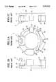
- the X-ray CT apparatus 100which amplifies the sectional image signal has, as shown in FIG. 1, a rotating portion 3 consisting of an X-ray tube unit 13 for irradiating X-ray, an X-ray tube cooling unit 15 for cooling the X-ray tube, an X-ray detection unit 17 for detecting the X-ray irradiated and passed through the object, a signal amplifier unit 19 for amplifying the signal detected by the X-ray detection unit 17, a mechanical control unit 21 for controlling the rotation of the rotating portion 11, and a power source unit 23 for supplying the power to the X-ray tube unit 13, the X-ray tube cooling unit 15, the X-ray detection unit 17, the signal amplifier units 19 and the mechanical control unit 21, and these units are fixed by bolts 25 on a rotating base 11 in the X-ray CT gantry 10.
- an object of the present inventionis to provide an X-ray CT apparatus capable of rotating a rotating portion at a high-speed without making the rotating portion larger.
- an X-ray CT apparatuscomprising of an X-ray CT gantry for irradiating X-ray to an object to be inspected for producing a sectional image signal relating to the object.
- the X-ray CT gantryhas a rotating base, a plurality of units fixed on one side of the rotating base, and fixing means for integrally fixing the plurality of units at portions thereof opposite to portions thereof fixed on the rotating base.
- the X-ray CT apparatushas a control unit for controlling movements of the X-ray CT gantry and for image processing the sectional image signal to display the image, and a couch for carrying the object thereon.
- this inventionhas more strength of a rotating portion against centrifugal force when rotating the rotating portion, since fixing members are provided for integrally fixing the plurality of units at portions thereof opposite to portions thereof fixed on the rotating base.
- the fixing meansis a cloth band for tying around the plurality of units.
- the shape of the cloth bandis unchangeable.
- the fixing meansis a rigid member for fixing the units adjacent to each other.
- the fixing meansis an annular fixing member.
- the annular fixing memberis fixed on surfaces of the plurality of units opposite to surfaces thereof fixed on the rotating base.
- this inventionprovides the X-ray CT apparatus comprising the X-ray CT gantry having the plurality of units and the rotating base which the units are fixed to.
- the X-ray CT gantryirradiates X-ray to the object to be inspected for producing the sectional image signal relating to the object.
- the X-ray CT apparatushas a control units for controlling the movements of the X-ray CT gantry and for image processing the sectional image signal to display the image, and a couch for carrying the object thereon.
- the rotating basecomprises a disc member and a cylindrical member for covering an outer periphery of the disc member.
- the plurality of unitsare fixed in holes provided at adjacent to the outer periphery of the disc member.
- the rotating basecomprises two annular members arranged parallel each other and a cylindrical member consisting of a plurality of bars for connecting the two annular members.
- the rotating basecomprises a disc member and a plurality of fixing members which are formed integrally with the disc member for fixing said plurality of units.
- this inventionprovides the X-ray CT apparatus comprising an X-ray CT gantry having the rotating base comprising the disc member and the cylindrical member for covering the outer periphery of the disc member, and having the plurality of units being fixed on one side of the disc member and/or on an inner surface of the cylindrical member.
- the X-ray CT gantryirradiates X-ray to the object to be inspected and for producing the sectional image signal relating to the object.
- the X-ray CT apparatushas a control unit for controlling the movements of the X-ray CT gantry and for image processing the sectional image signal to display the image, and a couch for carrying the object thereon.
- FIGS. 1A, 1B, and 1Care schematic views of a rotating portion in a conventional X-ray CT apparatus
- FIGS. 2A, 2B, and 2Care schematic views of a rotating portion according to a first embodiment of this invention.
- FIGS. 3A, 3B, and 3Care schematic views of a rotating portion according to a second embodiment of this invention.
- FIGS. 4A, 4B, and 4Care schematic variant views of a rotating portion according to a second embodiment of this invention.
- FIG. 5Ais another schematic variant view of a rotating portion according to a second embodiment of this invention.
- FIG. 5Bis a schematic detailed view of a square pipe when used as a fixing member
- FIG. 6is a schematic front view of a rotating portion according to a third embodiment of this invention.
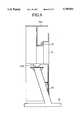
- FIG. 7is a schematic inside view of an X-ray CT gantry according to a fourth embodiment of this invention.
- FIG. 8is a schematic perspective view of a rotating portion in an X-ray CT gantry according to a fourth embodiment of this invention.
- FIG. 9is a schematic partial sectional view of an X-ray CT gantry of this invention.
- FIG. 10is a schematic view of a stand provided for a variant rotating portion according to fourth embodiment of this invention.
- FIG. 11is a schematic view of a variant rotating base according to a fourth embodiment of this invention.
- FIG. 12is a schematic plan view of a rotating base according to a fifth embodiment of this invention.
- FIG. 13is a schematic general view of an X-ray CT apparatus.
- the entire structure of an X-ray CT apparatus in this inventionis substantially the same as a conventional apparatus such as an X-ray CT apparatus 1 as shown in FIG. 13.
- the X-ray CT apparatus 1comprises an X-ray CT gantry 10 for irradiating X-ray to an object to be inspected to obtain a sectional image signal relating to the object, a control unit 50 for controlling movements of the X-ray CT gantry 10 and for image processing of the sectional image signal provided by the X-ray CT gantry 10 to display a processed image signal, and a couch 70 for carrying the object thereon.
- the X-ray CT gantry 10provides a rotating portion for rotating at a high speed.
- FIGS. 2A, 2B, and 2Care schematic views of a rotating portion 3a of a first embodiment of this invention, wherein FIG. 2A is a front view of the rotating portion 3a, FIG. 2B is a left side view and FIG. 2C is a right side view.
- the rotating portion 3acomprises an X-ray tube unit 13, an X-ray tube cooling unit 15, an X-ray detection unit 17, a signal amplifier unit 19, a mechanical control unit 21, and a power source unit 23. These units are fixed by bolts 25 on a rotating base 11 and are tied around by a band 30.
- the band 30may be made of an unshrinkable and inextensible cloth such as an unshrinkable and inextensible nylon band, namely a nylon sling.
- a metalsuch as a wire or a steed belt may also be used.
- a band of any materialmay be used as long as its shape remains unchanged.
- the band 30is fastened as follows.
- the X-ray tube unit 13, the X-ray tube cooling unit 15, the X-ray detection unit 17, the signal amplifier unit 19, the mechanical control unit 21, and the power source unit 23are fixed on the rotating base 11 by bolts 25 in the conventional manner.
- the band 30is placed around the plurality of units. Then, the band 30 is tightened so as not to drop from the units, neither the plurality of units drop out of the rotating portion 11.
- the band 30is fixed in the same manner by a buckle of a body belt (pants belt ).
- the fixing memberis not limited to the buckle of the body belt, other band fixing member may be used. Further, instead of employing the band fixing member, an adhesive may be used as a fixing member.
- the X-ray CT apparatuscomprises the X-ray tube unit 13, the X-ray tube cooling unit 15, the X-ray detection unit 17, the signal amplifier unit 19, the mechanical control unit 21, and the power source unit 23. These units are fixed on the rotating base 11 by bolts 25 and secured by the band 30. When the rotating portion is rotated, centrifugal force between the units diametrically opposing to each other (180° in the opposite direction) is offset. Thus, this structure provides a high-speed rotating portion 3a without making bolts 25 larger, increasing their numbers, consequently, the X-ray CT apparatus 1 itself is prevented from being made larger.
- the first embodimenthas an advantage of providing an easy manufacturing, though a degree of precision of positioning of each unit is not so high as compared with other embodiments.
- FIGS. 3A, 3B, and 3Care schematic views of a rotating portion 3b1 of the second embodiment of this invention, wherein FIG. 3A is a front view of the rotating portion, FIG. 3B is a left side view, and FIG. 3C is a right side view.
- the appearance of the X-ray CT apparatus of the second embodimentis substantially the same as that of the first embodiment as shown in FIGS. 2A, 2B, and 2C, and therefore the details are omitted from the drawing and the description.
- the rotating portion 3b1comprises the X-ray tube unit 13, the X-ray tube cooling unit 15, the X-ray detection unit 17, the signal amplifier unit 19, the mechanical control unit 21, and the power source unit 23. These units are fixed by bolts 25 on the rotating base 11 and connected adjacent units each other by fixing member 40.
- the fixing members 40are made by rigid body such as metal or ceramics etc., are formed corresponding to the shapes of the plurality of units and distance among the units. Fixing members are connected to the units by fixing-member-bolts 40a. Female screws (not shown) which correspond to fixing-member-bolts 40a are provided at a desirable position on each unit. Fixing members 40 have penetrating holes (not shown) to be penetrated by fixing-member-bolts 40a. In this case, as described above, fixing members 40 are connected to the units by fixing-member-bolts 40a. Besides, a bolt may be projected from each unit. A fixing member 40 may have a perpetration to be penetrated by the bolt and to be fixed from the top of it by a nut.
- the second embodimentprovides a higher degree of precision of positioning of each unit and increasing loads for each bolt compared with the first embodiment.
- the fixing member 40is connected to an outer surface of each unit, but fixing member 40 may be connected to any surface such as an inside surface of each unit or on the surface thereof.
- FIGS. 4A, 4B, and 4Care schematic variant views of a rotating portion 3b2 of the second embodiment of this invention, wherein FIG. 4A is a front view of the rotating portion 3b2, FIG. 4C is a right side view, FIG. 4B is a left side view.
- fixing members 40are fixed at one opposite side of another side which is fixed to the rotating base of each unit.
- FIG. 5Ais another schematic variant view of the rotating portion 3b3 according to the second embodiment of this invention.
- fixing members 40are connected at the opposite sides of each unit.
- a square pipe or a round pipemay be used for a fixing member 40.
- FIG. 5Bis a schematic detailed view of the square pipe when it is used for a fixing member. As shown in the same figure, flange portions are provided at the ends of the pipe, respectively. The square pipes are secured by bolts and the like on each unit. When each square pipe or round pipe used for a fixing member has a higher strength than when used a plate for a fixing member.
- the X-ray CT apparatuscomprises the X-ray tube unit 13, the X-ray tube cooling unit 15, the X-ray detection unit 17, the signal amplifier unit 19, the mechanical control unit 21, and the power source unit 23. These units are fixed by bolts 25 on the rotating base 11 and connected to adjacent units by rigid fixing members 40. When the rotating portion 3b is rotated, centrifugal force is distributed to adjacent units each other and offset between the units diametrically opposing to each other (180° in the opposite direction). Thus this structure provides the rotating portion 3b for rotating at a high speed without making bolts 25 larger and increasing their numbers, consequently, the X-ray CT apparatus itself is prevented from being made larger.
- FIG. 6is a schematic front view of a rotating portion 3C according to the third embodiment of this invention.
- the appearance of the X-ray CT apparatus of the third embodimentis substantially the same as that of the first embodiment as shown in FIGS. 2A, 2B, and 2C, and therefore the details are omitted from the drawing and the description.
- the X-ray CT apparatuscomprises the X-ray tube unit 13, the X-ray tube unit 15, the X-ray detection unit 17, the signal amplifier unit 19, the mechanical control unit 21, and the power source unit 23. These units are fixed by bolts 25 on the rotating base 11 and surfaces of the units are connected by annular fixing members 41, respectively.
- the annular fixing member 41is made by rigid body such as metal or ceramics, and formed corresponding to the location of each unit.
- the height of each unitmay be uniformed each other corresponding to the rotating portion 11.
- An annular fixing member 41itself may have steps in accordance with the height of each unit.
- Annular fixing members 41are connected to the units by fixing-member-bolts 41a.
- Female screws (not shown)which correspond to fixing-member-bolts 41a are provided at a desirable position on each unit.
- Annular fixing members 41have penetrations holes (not shown) to be penetrated by fixing-member-bolts 41a and are fixed by them. Further, an adhesive or welding may also be used instead of using fixing member-bolts 41a.
- the X-ray CT apparatuscomprises the X-ray tube unit 13, the X-ray tube cooling unit 15, the X-ray detection unit 17, the signal amplifier unit 19, the mechanical control unit 21, and the power source unit 23. These are fixed by bolts 25 and secured by annular fixing members 41.
- the rotating portion 3cWhen the rotating portion 3c is rotated, centrifugal force is distributed to adjacent units and offset between the units diametrically opposing to each other (180° in the opposite direction).
- this structureprovides the rotating portion 3c for rotating at a high-speed.
- Bolts 25which secure each unit are prevented from being made larger.
- FIG. 7is a schematic view of the internal structure of a fourth embodiment of an X-ray CT gantry 10 of this invention.
- FIG. 8is a schematic perspective view of a rotating portion 3d of the X-ray CT gantry 10 according to the fourth embodiment.
- FIG. 9is a schematic partial side view of the X-ray CT gantry 10 and a part of section viewed from the side of the rotating portion 3d of the X-ray CT gantry 10.
- the appearance of the X-ray CT apparatus in the fourth embodimentis substantially the same with that of the first embodiment as shown in FIGS. 2A, 2B, and 2C, and details are, therefore, omitted from the drawing and the description.
- the X-ray CT gantry 10comprises a rotating portion 3d, a fixing gantry 31, a support 33, and a base 35.
- the fixing gantry 31 and the rotating portion 3dare supported by the base 35 and the support 33.
- the rotating portion 3dis rotatable with respect to the fixing gantry 31 by means of through the bearing 37.
- the fixing gantry 31is capable of tilting against the support 33 by a rotating shaft 31a. Therefore, the rotating portion 3d is also capable of tilting against the support 33.
- the rotating base 11ahas a T-shaped section of the circumference.
- a disc portion on the rotating base 11ahaving holes 111 corresponding to the plurality of units such as the X-ray tube unit 13, the X-ray tube cooling unit 15, the X-ray detection unit 17, the signal amplifier unit 19, and the power source unit 23, etc., respectively.
- the rotating base 11bare fixed with the units by the holes 111. In FIG. 9, details of each unit are omitted.
- the units adjacent to the circumferencemay be fixed thereto.
- a hole 113is for the light weighting and the heat radiation of the rotating base 11a.
- the holes on the disc of the rotating base 11afix the X-ray tube unit 13, the X-ray tube cooling unit 15, the X-ray detection unit 17, the signal amplifier unit 19, and the power source unit 23, etc.
- the center of gravityis supported at an internal surface of the holes.
- the inner surfacereceives on centrifugal force without concentrating centrifugal force at one point such as the screw which supports each unit in the first, second, and third embodiments.
- each unitcan be securely supported, and problem of concentration of centrifugal force to the screw portion is resolved. Consequently, the durability of providing units is improved.
- the rotating base 11ahas a section of the L-shaped circumference thereof.
- an inner surface of a rotating base 11b and/or one side of the disc portionare/is for fixing the plurality of units comprising such as the X-ray tube unit, the X-ray tube cooling unit, the X-ray detection unit, the signal amplifier unit, and the power source unit etc.
- a stand 115 as shown in FIG. 8is provided to a position of which the units in the inner surface of the 11b is fixed so as that a fixing surface opposite to inner surface of the units in close contact of the inner surface of the unit, and fixed by fixing bolts.
- the unitmay be fixed directly to the inner surface of the rotating base 11 instead of providing the stand 115.
- the stand 115may be extended from the inner surface of the rotating base 11b to fix the units.
- a cylindrical rotating bases 11a, 11bare employed, however a rotating base having a shape of cylinder may be employed, wherein the rotating base comprises two annular members 81a, 81b disposed parallel each other and a plurality of bars 83 for connecting the two annular members 81a, 81b as shown in FIG. 11.
- the stand 115is provided inside at least two bars 83.
- each unitmay be fixed directly to the bars 83 without providing the stand 115.
- the rotating base 11c as described abovehas an advantage of the light weighting of a whole apparatus and easily releasing the produced heat.
- FIG. 12is a schematic plain view of a rotating base 11d disposed in an X-ray CT apparatus according to a fifth embodiment of this invention.
- the appearance of the X-ray CT apparatus in the fifth embodimentis substantially the same with that of the first embodiment as shown in FIGS. 2A, 2B, and 2C, and therefore details are omitted from the drawing and the description.
- the X-ray CT apparatuscomprises the rotating base 11d integrally formed with a plurality of unit fixing members 91 for fixing the X-ray tube unit 13, the X-ray tube cooling unit 15, the X-ray detection unit 17, the signal amplifier unit 19, the mechanical control unit 21, and the power source unit 23.
- the unitsare fixed by the unit fixing member 91 disposed on the rotating base 11d.
- the fixing members 91 for fixing the unitscomprises plates each having substantially a U-shaped cross section and corresponding to the size of each unit.
- the unitsare fixed to the corresponding fixing members 91 by bolts.
- the X-ray CT apparatuscomprises the rotating base 11d integrally formed with the fixing member 91 for fixing the X-ray tube unit 13, the X-ray cooling unit 15, the X-ray detection unit 17, the signal amplifier unit 19, the mechanical control unit 21, and the power source unit 23.
- the rotating portionhas an increase durability against centrifugal force when the rotating portion is rotating, and a high-speed rotation of the rotating portion is , therefore, possible without making it larger.
- the X-ray CT apparatushas a fixing means such as a band for integrally fixing the plurality of units at the portions thereof opposite to another portions which are disposed on the rotating base 11d. Consequently, even if the rotating portion rotate at high speed, strength of the rotating base increases against centrifugal force.
- the rotating baseitself is so structured to support each unit against centrifugal force, thereby the strength of the rotating base is improved.
Landscapes
- Health & Medical Sciences (AREA)
- Life Sciences & Earth Sciences (AREA)
- Engineering & Computer Science (AREA)
- Medical Informatics (AREA)
- Radiology & Medical Imaging (AREA)
- Molecular Biology (AREA)
- Biophysics (AREA)
- Nuclear Medicine, Radiotherapy & Molecular Imaging (AREA)
- Optics & Photonics (AREA)
- Pathology (AREA)
- Physics & Mathematics (AREA)
- Biomedical Technology (AREA)
- Heart & Thoracic Surgery (AREA)
- High Energy & Nuclear Physics (AREA)
- Surgery (AREA)
- Animal Behavior & Ethology (AREA)
- General Health & Medical Sciences (AREA)
- Public Health (AREA)
- Veterinary Medicine (AREA)
- Pulmonology (AREA)
- Theoretical Computer Science (AREA)
- Apparatus For Radiation Diagnosis (AREA)
Abstract
Description
1. Field of the Invention
This invention relates to an X-ray computed tomography apparatus for producing a slice image of an object to be inspected, more particularly to an X-ray computed tomography apparatus having a rotating portion for rotating at a high-speed to obtain a slice image relating to the object.
2. Description of the Prior Art
FIG. 13 shows a conventional X-ray computed tomography (hereinafter called X-ray CT)apparatus 100 comprising anX-ray CT gantry 10 for irradiating X-ray to an object to be inspected to obtain a sectional image signal of the object, acontrol unit 50 for controlling movements of theX-ray CT gantry 10 and for image processing of the sectional image signal obtained by theX-ray CT gantry 10 to display a processed image signal, and acouch 70 for carrying the object thereon, wherein each cable for connecting a rotating portion with a stationary portion in theX-ray CT gantry 10 is substituted by a slip ring. However, with this apparatus there is a possibility of having errors in signal transmissions due to use of slip rings. To avoid such errors, an apparatus which amplifies the obtained sectional image signal at the rotating side has been developed.
TheX-ray CT apparatus 100 which amplifies the sectional image signal has, as shown in FIG. 1, a rotatingportion 3 consisting of anX-ray tube unit 13 for irradiating X-ray, an X-raytube cooling unit 15 for cooling the X-ray tube, anX-ray detection unit 17 for detecting the X-ray irradiated and passed through the object, asignal amplifier unit 19 for amplifying the signal detected by theX-ray detection unit 17, amechanical control unit 21 for controlling the rotation of the rotatingportion 11, and apower source unit 23 for supplying the power to theX-ray tube unit 13, the X-raytube cooling unit 15, theX-ray detection unit 17, thesignal amplifier units 19 and themechanical control unit 21, and these units are fixed bybolts 25 on arotating base 11 in theX-ray CT gantry 10.
However, recently, with theX-ray CT apparatus 100 as shown in FIG. 13, it tends to use the apparatus by rotating the rotating portion of theX-ray CT gantry 10 at a high-speed for the purpose of shortening a time of inspection. Particularly, with the X-ray CT apparatus having a high-speed scanning of less than one second per a cycle of one scan,bolts 25 should be made larger and increased these numbers due to an increase of centrifugal force by the high speed rotation. There is a problem that the rotatingportion 3 is made larger, consequently, it results in making theX-ray CT apparatus 100 itself larger.
It is therefore an object of the present invention is to provide an X-ray CT apparatus capable of rotating a rotating portion at a high-speed without making the rotating portion larger.
In accordance with this invention, there is provided an X-ray CT apparatus comprising of an X-ray CT gantry for irradiating X-ray to an object to be inspected for producing a sectional image signal relating to the object. The X-ray CT gantry has a rotating base, a plurality of units fixed on one side of the rotating base, and fixing means for integrally fixing the plurality of units at portions thereof opposite to portions thereof fixed on the rotating base. The X-ray CT apparatus has a control unit for controlling movements of the X-ray CT gantry and for image processing the sectional image signal to display the image, and a couch for carrying the object thereon.
According to this invention, it has more strength of a rotating portion against centrifugal force when rotating the rotating portion, since fixing members are provided for integrally fixing the plurality of units at portions thereof opposite to portions thereof fixed on the rotating base.
According to a preferable embodiment of this invention, the fixing means is a cloth band for tying around the plurality of units. The shape of the cloth band is unchangeable.
According to a preferable embodiment of this invention, the fixing means is a rigid member for fixing the units adjacent to each other.
According to a preferable embodiment of this invention, the fixing means is an annular fixing member. The annular fixing member is fixed on surfaces of the plurality of units opposite to surfaces thereof fixed on the rotating base.
In accordance with this invention, this invention provides the X-ray CT apparatus comprising the X-ray CT gantry having the plurality of units and the rotating base which the units are fixed to. The X-ray CT gantry irradiates X-ray to the object to be inspected for producing the sectional image signal relating to the object. The X-ray CT apparatus has a control units for controlling the movements of the X-ray CT gantry and for image processing the sectional image signal to display the image, and a couch for carrying the object thereon.
According to a preferable embodiment of this invention, the rotating base comprises a disc member and a cylindrical member for covering an outer periphery of the disc member. The plurality of units are fixed in holes provided at adjacent to the outer periphery of the disc member.
According to a preferable embodiment of this invention, the rotating base comprises two annular members arranged parallel each other and a cylindrical member consisting of a plurality of bars for connecting the two annular members.
According to a preferable embodiment of this invention, the rotating base comprises a disc member and a plurality of fixing members which are formed integrally with the disc member for fixing said plurality of units.
In accordance with this invention, this invention provides the X-ray CT apparatus comprising an X-ray CT gantry having the rotating base comprising the disc member and the cylindrical member for covering the outer periphery of the disc member, and having the plurality of units being fixed on one side of the disc member and/or on an inner surface of the cylindrical member. The X-ray CT gantry irradiates X-ray to the object to be inspected and for producing the sectional image signal relating to the object. The X-ray CT apparatus has a control unit for controlling the movements of the X-ray CT gantry and for image processing the sectional image signal to display the image, and a couch for carrying the object thereon.
The nature, principle and utility of the invention will become more apparent from the following detailed description when read in conjunction with the accompanying drawings.
In the accompanying drawings:
FIGS. 1A, 1B, and 1C are schematic views of a rotating portion in a conventional X-ray CT apparatus;
FIGS. 2A, 2B, and 2C are schematic views of a rotating portion according to a first embodiment of this invention;
FIGS. 3A, 3B, and 3C are schematic views of a rotating portion according to a second embodiment of this invention;
FIGS. 4A, 4B, and 4C are schematic variant views of a rotating portion according to a second embodiment of this invention;
FIG. 5A is another schematic variant view of a rotating portion according to a second embodiment of this invention;
FIG. 5B is a schematic detailed view of a square pipe when used as a fixing member;
FIG. 6 is a schematic front view of a rotating portion according to a third embodiment of this invention;
FIG. 7 is a schematic inside view of an X-ray CT gantry according to a fourth embodiment of this invention;
FIG. 8 is a schematic perspective view of a rotating portion in an X-ray CT gantry according to a fourth embodiment of this invention;
FIG. 9 is a schematic partial sectional view of an X-ray CT gantry of this invention;
FIG. 10 is a schematic view of a stand provided for a variant rotating portion according to fourth embodiment of this invention;
FIG. 11 is a schematic view of a variant rotating base according to a fourth embodiment of this invention;
FIG. 12 is a schematic plan view of a rotating base according to a fifth embodiment of this invention; and
FIG. 13 is a schematic general view of an X-ray CT apparatus.
The preferred embodiment of this invention shall be clearly understood from the following description by referring to accompanying drawings.
The entire structure of an X-ray CT apparatus in this invention is substantially the same as a conventional apparatus such as an X-ray CT apparatus 1 as shown in FIG. 13. The X-ray CT apparatus 1 comprises anX-ray CT gantry 10 for irradiating X-ray to an object to be inspected to obtain a sectional image signal relating to the object, acontrol unit 50 for controlling movements of theX-ray CT gantry 10 and for image processing of the sectional image signal provided by theX-ray CT gantry 10 to display a processed image signal, and acouch 70 for carrying the object thereon. Specifically, the X-rayCT gantry 10 provides a rotating portion for rotating at a high speed.
FIGS. 2A, 2B, and 2C are schematic views of a rotatingportion 3a of a first embodiment of this invention, wherein FIG. 2A is a front view of the rotatingportion 3a, FIG. 2B is a left side view and FIG. 2C is a right side view.
According to the first embodiment of this invention, as shown in FIGS. 2A, 2B, and 2C, the rotatingportion 3a comprises anX-ray tube unit 13, an X-raytube cooling unit 15, anX-ray detection unit 17, asignal amplifier unit 19, amechanical control unit 21, and apower source unit 23. These units are fixed bybolts 25 on a rotatingbase 11 and are tied around by aband 30.
Theband 30 may be made of an unshrinkable and inextensible cloth such as an unshrinkable and inextensible nylon band, namely a nylon sling. A metal such as a wire or a steed belt may also be used. Thus, a band of any material may be used as long as its shape remains unchanged.
Theband 30 is fastened as follows.
TheX-ray tube unit 13, the X-raytube cooling unit 15, theX-ray detection unit 17, thesignal amplifier unit 19, themechanical control unit 21, and thepower source unit 23 are fixed on the rotatingbase 11 bybolts 25 in the conventional manner.
Subsequently, theband 30 is placed around the plurality of units. Then, theband 30 is tightened so as not to drop from the units, neither the plurality of units drop out of the rotatingportion 11. Theband 30 is fixed in the same manner by a buckle of a body belt (pants belt ). As for the fixing member is not limited to the buckle of the body belt, other band fixing member may be used. Further, instead of employing the band fixing member, an adhesive may be used as a fixing member.
As described above, in the X-ray CT apparatus according to the first embodiment, the X-ray CT apparatus comprises theX-ray tube unit 13, the X-raytube cooling unit 15, theX-ray detection unit 17, thesignal amplifier unit 19, themechanical control unit 21, and thepower source unit 23. These units are fixed on the rotatingbase 11 bybolts 25 and secured by theband 30. When the rotating portion is rotated, centrifugal force between the units diametrically opposing to each other (180° in the opposite direction) is offset. Thus, this structure provides a high-speed rotating portion 3a without makingbolts 25 larger, increasing their numbers, consequently, the X-ray CT apparatus 1 itself is prevented from being made larger. The first embodiment has an advantage of providing an easy manufacturing, though a degree of precision of positioning of each unit is not so high as compared with other embodiments.
The description will now proceed to a second embodiment of this invention.
FIGS. 3A, 3B, and 3C are schematic views of a rotating portion 3b1 of the second embodiment of this invention, wherein FIG. 3A is a front view of the rotating portion, FIG. 3B is a left side view, and FIG. 3C is a right side view. The appearance of the X-ray CT apparatus of the second embodiment is substantially the same as that of the first embodiment as shown in FIGS. 2A, 2B, and 2C, and therefore the details are omitted from the drawing and the description.
According to the second embodiment of this invention, as shown in FIGS. 3A, 3B, and 3C, the rotating portion 3b1 comprises theX-ray tube unit 13, the X-raytube cooling unit 15, theX-ray detection unit 17, thesignal amplifier unit 19, themechanical control unit 21, and thepower source unit 23. These units are fixed bybolts 25 on the rotatingbase 11 and connected adjacent units each other by fixingmember 40.
The fixingmembers 40 are made by rigid body such as metal or ceramics etc., are formed corresponding to the shapes of the plurality of units and distance among the units. Fixing members are connected to the units by fixing-member-bolts 40a. Female screws (not shown) which correspond to fixing-member-bolts 40a are provided at a desirable position on each unit. Fixingmembers 40 have penetrating holes (not shown) to be penetrated by fixing-member-bolts 40a. In this case, as described above, fixingmembers 40 are connected to the units by fixing-member-bolts 40a. Besides, a bolt may be projected from each unit. A fixingmember 40 may have a perpetration to be penetrated by the bolt and to be fixed from the top of it by a nut.
Further, an adhesive or welding may also be used instead of fixing-member-bolts 40a. The second embodiment provides a higher degree of precision of positioning of each unit and increasing loads for each bolt compared with the first embodiment.
In the case of the rotating portion 3b1 according to the second embodiment as shown in FIG. 3, the fixingmember 40 is connected to an outer surface of each unit, but fixingmember 40 may be connected to any surface such as an inside surface of each unit or on the surface thereof.
FIGS. 4A, 4B, and 4C are schematic variant views of a rotating portion 3b2 of the second embodiment of this invention, wherein FIG. 4A is a front view of the rotating portion 3b2, FIG. 4C is a right side view, FIG. 4B is a left side view. In this variant case, fixingmembers 40 are fixed at one opposite side of another side which is fixed to the rotating base of each unit.
FIG. 5A is another schematic variant view of the rotating portion 3b3 according to the second embodiment of this invention. In this variant case, fixingmembers 40 are connected at the opposite sides of each unit. In this case, a square pipe or a round pipe may be used for a fixingmember 40. FIG. 5B is a schematic detailed view of the square pipe when it is used for a fixing member. As shown in the same figure, flange portions are provided at the ends of the pipe, respectively. The square pipes are secured by bolts and the like on each unit. When each square pipe or round pipe used for a fixing member has a higher strength than when used a plate for a fixing member.
According to the second embodiment of this invention, the X-ray CT apparatus comprises theX-ray tube unit 13, the X-raytube cooling unit 15, theX-ray detection unit 17, thesignal amplifier unit 19, themechanical control unit 21, and thepower source unit 23. These units are fixed bybolts 25 on the rotatingbase 11 and connected to adjacent units byrigid fixing members 40. When the rotating portion 3b is rotated, centrifugal force is distributed to adjacent units each other and offset between the units diametrically opposing to each other (180° in the opposite direction). Thus this structure provides the rotating portion 3b for rotating at a high speed without makingbolts 25 larger and increasing their numbers, consequently, the X-ray CT apparatus itself is prevented from being made larger.
The description will now proceed to a third embodiment.
FIG. 6 is a schematic front view of a rotating portion 3C according to the third embodiment of this invention. The appearance of the X-ray CT apparatus of the third embodiment is substantially the same as that of the first embodiment as shown in FIGS. 2A, 2B, and 2C, and therefore the details are omitted from the drawing and the description.
As shown in FIG. 6, in the third embodiment, the X-ray CT apparatus comprises theX-ray tube unit 13, theX-ray tube unit 15, theX-ray detection unit 17, thesignal amplifier unit 19, themechanical control unit 21, and thepower source unit 23. These units are fixed bybolts 25 on the rotatingbase 11 and surfaces of the units are connected byannular fixing members 41, respectively.
Theannular fixing member 41 is made by rigid body such as metal or ceramics, and formed corresponding to the location of each unit. The height of each unit may be uniformed each other corresponding to the rotatingportion 11. An annular fixingmember 41 itself may have steps in accordance with the height of each unit.
Annular fixingmembers 41 are connected to the units by fixing-member-bolts 41a. Female screws (not shown) which correspond to fixing-member-bolts 41a are provided at a desirable position on each unit. Annular fixingmembers 41 have penetrations holes (not shown) to be penetrated by fixing-member-bolts 41a and are fixed by them. Further, an adhesive or welding may also be used instead of using fixing member-bolts 41a.
In this embodiment, there is an advantage of preventing each unit from moving forward, though an efficiency of maintenance decreases.
in this embodiment, the X-ray CT apparatus comprises theX-ray tube unit 13, the X-raytube cooling unit 15, theX-ray detection unit 17, thesignal amplifier unit 19, themechanical control unit 21, and thepower source unit 23. These are fixed bybolts 25 and secured byannular fixing members 41. When therotating portion 3c is rotated, centrifugal force is distributed to adjacent units and offset between the units diametrically opposing to each other (180° in the opposite direction). Thus this structure provides therotating portion 3c for rotating at a high-speed.Bolts 25 which secure each unit are prevented from being made larger.
FIG. 7 is a schematic view of the internal structure of a fourth embodiment of anX-ray CT gantry 10 of this invention. FIG. 8 is a schematic perspective view of arotating portion 3d of theX-ray CT gantry 10 according to the fourth embodiment. FIG. 9 is a schematic partial side view of theX-ray CT gantry 10 and a part of section viewed from the side of therotating portion 3d of theX-ray CT gantry 10. The appearance of the X-ray CT apparatus in the fourth embodiment is substantially the same with that of the first embodiment as shown in FIGS. 2A, 2B, and 2C, and details are, therefore, omitted from the drawing and the description.
TheX-ray CT gantry 10 according to the fourth embodiment comprises arotating portion 3d, a fixinggantry 31, asupport 33, and abase 35. The fixinggantry 31 and therotating portion 3d are supported by thebase 35 and thesupport 33. As shown in FIG. 9, the rotatingportion 3d is rotatable with respect to the fixinggantry 31 by means of through thebearing 37. Furthermore, the fixinggantry 31 is capable of tilting against thesupport 33 by arotating shaft 31a. Therefore, the rotatingportion 3d is also capable of tilting against thesupport 33.
The detailed description will now proceed to therotating portion 3d according to the fourth embodiment.
In the fourth embodiment employing the rotatingbase 11a has a T-shaped section of the circumference. A disc portion on the rotatingbase 11a having holes 111 corresponding to the plurality of units such as theX-ray tube unit 13, the X-raytube cooling unit 15, theX-ray detection unit 17, thesignal amplifier unit 19, and thepower source unit 23, etc., respectively. The rotatingbase 11b are fixed with the units by theholes 111. In FIG. 9, details of each unit are omitted. The units adjacent to the circumference may be fixed thereto. Furthermore, ahole 113 is for the light weighting and the heat radiation of therotating base 11a.
According to the fourth embodiment, the holes on the disc of therotating base 11a fix theX-ray tube unit 13, the X-raytube cooling unit 15, theX-ray detection unit 17, thesignal amplifier unit 19, and thepower source unit 23, etc. The center of gravity is supported at an internal surface of the holes. The inner surface receives on centrifugal force without concentrating centrifugal force at one point such as the screw which supports each unit in the first, second, and third embodiments. Thus, each unit can be securely supported, and problem of concentration of centrifugal force to the screw portion is resolved. Consequently, the durability of providing units is improved. In the variation of the fourth embodiment, it is preferable that the rotatingbase 11a has a section of the L-shaped circumference thereof. In the case, an inner surface of arotating base 11b and/or one side of the disc portion are/is for fixing the plurality of units comprising such as the X-ray tube unit, the X-ray tube cooling unit, the X-ray detection unit, the signal amplifier unit, and the power source unit etc.
Astand 115 as shown in FIG. 8 is provided to a position of which the units in the inner surface of the 11b is fixed so as that a fixing surface opposite to inner surface of the units in close contact of the inner surface of the unit, and fixed by fixing bolts. The unit may be fixed directly to the inner surface of the rotatingbase 11 instead of providing thestand 115.
Furthermore, in the case of an arrangement of the X-ray detection unit is not located in the inner surface of therotating base 11b, thestand 115 may be extended from the inner surface of therotating base 11b to fix the units.
According to the embodiments shown in FIG. 7 and FIG. 10, a cylindricalrotating bases annular members bars 83 for connecting the twoannular members stand 115 is provided inside at least twobars 83. However, each unit may be fixed directly to thebars 83 without providing thestand 115. The rotatingbase 11c as described above has an advantage of the light weighting of a whole apparatus and easily releasing the produced heat.
FIG. 12 is a schematic plain view of arotating base 11d disposed in an X-ray CT apparatus according to a fifth embodiment of this invention. The appearance of the X-ray CT apparatus in the fifth embodiment is substantially the same with that of the first embodiment as shown in FIGS. 2A, 2B, and 2C, and therefore details are omitted from the drawing and the description.
According to the fifth embodiment as shown in FIG. 12, the X-ray CT apparatus comprises the rotatingbase 11d integrally formed with a plurality ofunit fixing members 91 for fixing theX-ray tube unit 13, the X-raytube cooling unit 15, theX-ray detection unit 17, thesignal amplifier unit 19, themechanical control unit 21, and thepower source unit 23. The units are fixed by theunit fixing member 91 disposed on the rotatingbase 11d.
The fixingmembers 91 for fixing the units comprises plates each having substantially a U-shaped cross section and corresponding to the size of each unit. The units are fixed to the corresponding fixingmembers 91 by bolts.
As described above, the X-ray CT apparatus according to the fifth embodiment comprises the rotatingbase 11d integrally formed with the fixingmember 91 for fixing theX-ray tube unit 13, theX-ray cooling unit 15, theX-ray detection unit 17, thesignal amplifier unit 19, themechanical control unit 21, and thepower source unit 23. Thus, the rotating portion has an increase durability against centrifugal force when the rotating portion is rotating, and a high-speed rotation of the rotating portion is , therefore, possible without making it larger.
As described above, the X-ray CT apparatus has a fixing means such as a band for integrally fixing the plurality of units at the portions thereof opposite to another portions which are disposed on the rotatingbase 11d. Consequently, even if the rotating portion rotate at high speed, strength of the rotating base increases against centrifugal force. In addition, the rotating base itself is so structured to support each unit against centrifugal force, thereby the strength of the rotating base is improved.
It should be understood that many modifications and adaptations of the invention will become apparent to those skilled in the art and it is intended to encompass such obvious modifications and changes in the scope of the claims appended hereto.
Claims (15)
1. An X-ray computed tomography apparatus comprising:
an X-ray computed tomography gantry for irradiating X-ray to an object to be inspected and for producing a sectional image signal relating to said object, said X-ray computed tomography gantry comprising a rotating base having a shape of disc, a plurality of units fixed on one side of said rotating base for processing X-ray, and fixing means for integrally fixing said plurality of units at portions thereof apart from portions thereof fixed on said rotating base;
control means for controlling movements of said X-ray computed tomography gantry and for image processing said sectional image signal to display the image; and
a couch for carrying said object thereon.
2. An X-ray computed tomography apparatus as claimed in claim 1, wherein said fixing means comprises a cloth band for tying around said plurality of units, said cloth band having unchangeable shape.
3. An X-ray computed tomography apparatus as claimed in claim 1, wherein said fixing means comprises a rigid fixing member for fixing said units adjacent to each other.
4. An X-ray computed tomography apparatus as claimed in claim 3, wherein said fixing means secures said adjacent units at outer periphery thereof.
5. An X-ray computed tomography apparatus as claimed in claim 3, wherein said fixing means secures said adjacent units on surfaces thereof opposite to surfaces thereof fixed on said rotating base.
6. An X-ray computed tomography apparatus as claimed in claim 3, wherein each unit is fixed diametrically opposite to the other units, respectively.
7. An X-ray computed tomography apparatus as claimed in claim 1, wherein said fixing means comprises an annular fixing member disposed on surfaces of said plurality of units opposite to surfaces thereof fixed on said rotating base.
8. An X-ray computed tomography apparatus as claimed in claim 1, wherein said apparatus has a scanning cycle of less than one second per a cycle of one scan.
9. An X-ray computed tomography apparatus comprising:
an X-ray computed tomography gantry for irradiating X-ray to an object to be inspected for producing a sectional image signal relating to said object, said X-ray computed tomography gantry having a plurality of units and a rotating base for fixing said plurality of units thereto, said rotating base having a disc member and a cylindrical member for covering an outer periphery of said disc member, and said plurality of units being fixed into holes formed on said disc member near the outer periphery thereof;
controlling means for controlling movements of said X-ray computed tomography gantry and for image processing said sectional image signal to display the image; and
a couch for carrying said object thereon.
10. An X-ray computed tomography apparatus as claimed in claim 9, wherein said X-ray computed tomography gantry further comprises a fixing gantry and a bearing, which is fixed on said fixing gantry, for rotatably supporting said rotating member on an inner diameter portion thereof.
11. An X-ray computed tomography apparatus as claimed in claim 9, wherein said cylindrical member comprises a hole for lightening and radiating heat.
12. An X-ray computed tomography apparatus as claimed in claim 10, wherein said cylindrical member comprises a hole for lightening and radiating heat.
13. An X-ray computed tomography apparatus comprising:
an X-ray computed tomography gantry for irradiating X-ray to an object to be inspected for producing a sectional image signal relating to said object, said X-ray computed tomography gantry having a plurality of units and a rotating base for fixing said plurality of units thereto, said rotating base having a disc member and a plurality of fixing members formed integrally with said disc member for fixing said plurality of units:
controlling means for controlling movements of said X-ray computed tomography gantry and for image processing said sectional image signal to display the image; and
a couch for carrying said object thereon.
14. An X-ray computed tomography apparatus comprising:
an X-ray computed tomography gantry for irradiating X-ray to an object to be inspected and for producing a sectional image signal relating to said object, said X-ray computed tomography gantry having a rotating base comprising a disc member and a cylindrical member for covering the outer periphery of said disc member, and having a plurality of units being fixed on one side of said disc member and/or on an inner surface of said cylindrical member;
controlling means for controlling movements of said X-ray computed tomography gantry and for processing said sectional image signal to display an image; and
a couch for carrying said object thereon.
15. An X-ray computed tomography apparatus as claimed in claim 14, wherein a stand is provided at a position of cylindrical member to which said unit is fixed, in such manner that a surface of said stand fixed on the inner surface of said cylindrical member is in close contact with the inner surface.
Applications Claiming Priority (2)
| Application Number | Priority Date | Filing Date | Title |
|---|---|---|---|
| JP13166495AJP3489757B2 (en) | 1994-06-07 | 1995-05-30 | X-ray CT system |
| JPP7-131664 | 1995-05-30 |
Publications (1)
| Publication Number | Publication Date |
|---|---|
| US5703921Atrue US5703921A (en) | 1997-12-30 |
Family
ID=15063345
Family Applications (1)
| Application Number | Title | Priority Date | Filing Date |
|---|---|---|---|
| US08/654,675Expired - LifetimeUS5703921A (en) | 1995-05-30 | 1996-05-29 | X-ray computed tomography apparatus |
Country Status (1)
| Country | Link |
|---|---|
| US (1) | US5703921A (en) |
Cited By (26)
| Publication number | Priority date | Publication date | Assignee | Title |
|---|---|---|---|---|
| US6314157B1 (en) | 1998-10-16 | 2001-11-06 | Kabushiki Kaisha Toshiba | Arrangements for mounting units in a computed tomography system |
| US6337894B1 (en)* | 2000-09-20 | 2002-01-08 | Analogic Corporation | Rotary bearing assembly for CT scanner gantry |
| EP1182911A1 (en)* | 2000-08-16 | 2002-02-27 | Analogic Corporation | System and method for mounting x-ray tube in CT scanner |
| US20040017895A1 (en)* | 2000-09-12 | 2004-01-29 | Tsutomu Suzuki | X-ray CT scanner |
| WO2005102171A1 (en)* | 2004-04-27 | 2005-11-03 | Koninklijke Philips Electronics, N.V. | Open access air bearing gantry |
| US20060018437A1 (en)* | 2004-07-23 | 2006-01-26 | Siemens Aktiengesellschaft | Tomography apparatus with gantry-carried component mounted to withstand centrifugal forces |
| US20070053479A1 (en)* | 2005-09-08 | 2007-03-08 | Tetsuya Sadatomo | X-ray computed tomographic apparatus |
| EP2047888A1 (en)* | 2007-10-12 | 2009-04-15 | Elekta AB (publ) | Radiotherapy apparatus and parts thereof |
| WO2009063354A1 (en) | 2007-11-16 | 2009-05-22 | Koninklijke Philips Electronics N.V. | High speed rotating gantry |
| CN100534389C (en)* | 2005-09-08 | 2009-09-02 | 株式会社东芝 | X-ray computed tomographic apparatus |
| US20100027759A1 (en)* | 2008-08-01 | 2010-02-04 | Daniela Luecke | Computed tomography rotor rigidified by a composite material with shaped bodies therein |
| US7734102B2 (en) | 2005-05-11 | 2010-06-08 | Optosecurity Inc. | Method and system for screening cargo containers |
| US7899232B2 (en) | 2006-05-11 | 2011-03-01 | Optosecurity Inc. | Method and apparatus for providing threat image projection (TIP) in a luggage screening system, and luggage screening system implementing same |
| US7991242B2 (en) | 2005-05-11 | 2011-08-02 | Optosecurity Inc. | Apparatus, method and system for screening receptacles and persons, having image distortion correction functionality |
| US8494210B2 (en) | 2007-03-30 | 2013-07-23 | Optosecurity Inc. | User interface for use in security screening providing image enhancement capabilities and apparatus for implementing same |
| US20130272489A1 (en)* | 2012-04-16 | 2013-10-17 | Neurologica Corp. | Imaging system with rigidly mounted fiducial markers |
| CN104840213A (en)* | 2014-02-19 | 2015-08-19 | Ge医疗系统环球技术有限公司 | Image collecting device for CT machine and related CT machine |
| US20150265229A1 (en)* | 2014-03-18 | 2015-09-24 | General Electric Company | Gantry with bore safety mechanism |
| US9204850B2 (en) | 2014-02-04 | 2015-12-08 | General Electric Company | Gantry with secondary safety mechanism |
| US20150366522A1 (en)* | 2014-06-19 | 2015-12-24 | Analogic Corporation | Radiation sources and detector array for imaging modality |
| US9351693B2 (en) | 2011-08-10 | 2016-05-31 | Konlijke Philips N.V. | Imaging system gantry tilt support |
| US20160249871A1 (en)* | 2014-02-04 | 2016-09-01 | General Electric Company | Interface for gantry and component |
| US9632206B2 (en) | 2011-09-07 | 2017-04-25 | Rapiscan Systems, Inc. | X-ray inspection system that integrates manifest data with imaging/detection processing |
| US10302807B2 (en) | 2016-02-22 | 2019-05-28 | Rapiscan Systems, Inc. | Systems and methods for detecting threats and contraband in cargo |
| US10383588B2 (en)* | 2016-05-16 | 2019-08-20 | Samsung Electronics Co., Ltd. | Gantry of computed tomography (CT) apparatus |
| WO2020082907A1 (en)* | 2018-10-26 | 2020-04-30 | 深圳市奥沃医学新技术发展有限公司 | Positioning mechanism and radiation therapy device |
Citations (7)
| Publication number | Priority date | Publication date | Assignee | Title |
|---|---|---|---|---|
| US4112303A (en)* | 1977-02-25 | 1978-09-05 | General Electric Company | Gantry for computed tomography |
| GB2026812A (en)* | 1978-07-28 | 1980-02-06 | Emi Ltd | Power supply arrangement for computerised tomographic apparatus |
| US4426715A (en)* | 1981-07-06 | 1984-01-17 | Siemens Aktiengesellschaft | Radiation diagnostic apparatus |
| JPS61201182A (en)* | 1985-03-04 | 1986-09-05 | Hitachi Medical Corp | Multi-element detector for x-ray ct device |
| US4646333A (en)* | 1983-07-29 | 1987-02-24 | Kabushiki Kaisha Toshiba | CT scanner |
| US4991190A (en)* | 1988-08-15 | 1991-02-05 | Kabushiki Kaisha Toshiba | Rotate-rotate type X-ray computerized tomographic imaging apparatus |
| US5448608A (en)* | 1994-02-08 | 1995-09-05 | Analogic Corporation | Tomographic scanner having center of rotation for all physics |
- 1996
- 1996-05-29USUS08/654,675patent/US5703921A/ennot_activeExpired - Lifetime
Patent Citations (7)
| Publication number | Priority date | Publication date | Assignee | Title |
|---|---|---|---|---|
| US4112303A (en)* | 1977-02-25 | 1978-09-05 | General Electric Company | Gantry for computed tomography |
| GB2026812A (en)* | 1978-07-28 | 1980-02-06 | Emi Ltd | Power supply arrangement for computerised tomographic apparatus |
| US4426715A (en)* | 1981-07-06 | 1984-01-17 | Siemens Aktiengesellschaft | Radiation diagnostic apparatus |
| US4646333A (en)* | 1983-07-29 | 1987-02-24 | Kabushiki Kaisha Toshiba | CT scanner |
| JPS61201182A (en)* | 1985-03-04 | 1986-09-05 | Hitachi Medical Corp | Multi-element detector for x-ray ct device |
| US4991190A (en)* | 1988-08-15 | 1991-02-05 | Kabushiki Kaisha Toshiba | Rotate-rotate type X-ray computerized tomographic imaging apparatus |
| US5448608A (en)* | 1994-02-08 | 1995-09-05 | Analogic Corporation | Tomographic scanner having center of rotation for all physics |
Cited By (51)
| Publication number | Priority date | Publication date | Assignee | Title |
|---|---|---|---|---|
| US6314157B1 (en) | 1998-10-16 | 2001-11-06 | Kabushiki Kaisha Toshiba | Arrangements for mounting units in a computed tomography system |
| EP1182911A1 (en)* | 2000-08-16 | 2002-02-27 | Analogic Corporation | System and method for mounting x-ray tube in CT scanner |
| US20040017895A1 (en)* | 2000-09-12 | 2004-01-29 | Tsutomu Suzuki | X-ray CT scanner |
| US6819737B2 (en)* | 2000-09-12 | 2004-11-16 | Hitachi Medical Corporation | X-ray CT scanner |
| US6337894B1 (en)* | 2000-09-20 | 2002-01-08 | Analogic Corporation | Rotary bearing assembly for CT scanner gantry |
| WO2002024072A1 (en)* | 2000-09-20 | 2002-03-28 | Analogic Corporation | Rotary bearing assembly for ct scanner gantry |
| US20070230654A1 (en)* | 2004-04-27 | 2007-10-04 | Koninklijke Philips Electronics N.V. | Open Access Air Bearing Gantry |
| WO2005102171A1 (en)* | 2004-04-27 | 2005-11-03 | Koninklijke Philips Electronics, N.V. | Open access air bearing gantry |
| US7477721B2 (en) | 2004-04-27 | 2009-01-13 | Koninklijke Philips Electronics N.V. | Open access air bearing gantry |
| DE102004035790B4 (en)* | 2004-07-23 | 2007-08-02 | Siemens Ag | tomograph |
| US7076018B2 (en)* | 2004-07-23 | 2006-07-11 | Siemens Aktiengesellschaft | Tomography apparatus with gantry-carried component mounted to withstand centrifugal forces |
| US20060018437A1 (en)* | 2004-07-23 | 2006-01-26 | Siemens Aktiengesellschaft | Tomography apparatus with gantry-carried component mounted to withstand centrifugal forces |
| US7734102B2 (en) | 2005-05-11 | 2010-06-08 | Optosecurity Inc. | Method and system for screening cargo containers |
| US7991242B2 (en) | 2005-05-11 | 2011-08-02 | Optosecurity Inc. | Apparatus, method and system for screening receptacles and persons, having image distortion correction functionality |
| US20070053479A1 (en)* | 2005-09-08 | 2007-03-08 | Tetsuya Sadatomo | X-ray computed tomographic apparatus |
| EP1762177A3 (en)* | 2005-09-08 | 2008-01-30 | Kabushiki Kaisha Toshiba | X-ray computed tomographic apparatus |
| US7447294B2 (en) | 2005-09-08 | 2008-11-04 | Kabushiki Kaisha Toshiba | X-ray computed tomographic apparatus |
| CN100534389C (en)* | 2005-09-08 | 2009-09-02 | 株式会社东芝 | X-ray computed tomographic apparatus |
| US7899232B2 (en) | 2006-05-11 | 2011-03-01 | Optosecurity Inc. | Method and apparatus for providing threat image projection (TIP) in a luggage screening system, and luggage screening system implementing same |
| US8494210B2 (en) | 2007-03-30 | 2013-07-23 | Optosecurity Inc. | User interface for use in security screening providing image enhancement capabilities and apparatus for implementing same |
| EP2047888A1 (en)* | 2007-10-12 | 2009-04-15 | Elekta AB (publ) | Radiotherapy apparatus and parts thereof |
| CN101854864B (en)* | 2007-11-16 | 2013-03-13 | 皇家飞利浦电子股份有限公司 | High speed rotating gantry |
| WO2009063354A1 (en) | 2007-11-16 | 2009-05-22 | Koninklijke Philips Electronics N.V. | High speed rotating gantry |
| US8681930B2 (en)* | 2007-11-16 | 2014-03-25 | Koninklijke Philips N.V. | High speed rotating gantry |
| US20100266105A1 (en)* | 2007-11-16 | 2010-10-21 | Koninklijke Philips Electronics N.V. | High speed rotating gantry |
| US8246247B2 (en)* | 2008-08-01 | 2012-08-21 | Siemens Aktiengesellschaft | Computed tomography rotor rigidified by a composite material with shaped bodies therein |
| US20100027759A1 (en)* | 2008-08-01 | 2010-02-04 | Daniela Luecke | Computed tomography rotor rigidified by a composite material with shaped bodies therein |
| US9351693B2 (en) | 2011-08-10 | 2016-05-31 | Konlijke Philips N.V. | Imaging system gantry tilt support |
| US10422919B2 (en) | 2011-09-07 | 2019-09-24 | Rapiscan Systems, Inc. | X-ray inspection system that integrates manifest data with imaging/detection processing |
| US12174334B2 (en) | 2011-09-07 | 2024-12-24 | Rapiscan Systems, Inc. | Distributed analysis X-ray inspection methods and systems |
| US11099294B2 (en) | 2011-09-07 | 2021-08-24 | Rapiscan Systems, Inc. | Distributed analysis x-ray inspection methods and systems |
| US10509142B2 (en) | 2011-09-07 | 2019-12-17 | Rapiscan Systems, Inc. | Distributed analysis x-ray inspection methods and systems |
| US10830920B2 (en) | 2011-09-07 | 2020-11-10 | Rapiscan Systems, Inc. | Distributed analysis X-ray inspection methods and systems |
| US9632206B2 (en) | 2011-09-07 | 2017-04-25 | Rapiscan Systems, Inc. | X-ray inspection system that integrates manifest data with imaging/detection processing |
| US20130272489A1 (en)* | 2012-04-16 | 2013-10-17 | Neurologica Corp. | Imaging system with rigidly mounted fiducial markers |
| US9173620B2 (en)* | 2012-04-16 | 2015-11-03 | Neurologica Corp. | Imaging system with rigidly mounted fiducial markers |
| US20160249871A1 (en)* | 2014-02-04 | 2016-09-01 | General Electric Company | Interface for gantry and component |
| US10791999B2 (en)* | 2014-02-04 | 2020-10-06 | General Electric Company | Interface for gantry and component |
| US9204850B2 (en) | 2014-02-04 | 2015-12-08 | General Electric Company | Gantry with secondary safety mechanism |
| US10219760B2 (en) | 2014-02-04 | 2019-03-05 | General Electric Company | Rotary member with safety mechanism |
| CN104840213B (en)* | 2014-02-19 | 2020-03-17 | Ge医疗系统环球技术有限公司 | Image acquisition device for CT machine and corresponding CT machine |
| CN104840213A (en)* | 2014-02-19 | 2015-08-19 | Ge医疗系统环球技术有限公司 | Image collecting device for CT machine and related CT machine |
| US9254108B2 (en)* | 2014-03-18 | 2016-02-09 | General Electric Company | Gantry with bore safety mechanism |
| US20150265229A1 (en)* | 2014-03-18 | 2015-09-24 | General Electric Company | Gantry with bore safety mechanism |
| US10178980B2 (en)* | 2014-06-19 | 2019-01-15 | Analogic Corporation | Radiation sources and detector array for imaging modality |
| US20150366522A1 (en)* | 2014-06-19 | 2015-12-24 | Analogic Corporation | Radiation sources and detector array for imaging modality |
| US10302807B2 (en) | 2016-02-22 | 2019-05-28 | Rapiscan Systems, Inc. | Systems and methods for detecting threats and contraband in cargo |
| US10768338B2 (en) | 2016-02-22 | 2020-09-08 | Rapiscan Systems, Inc. | Systems and methods for detecting threats and contraband in cargo |
| US11287391B2 (en) | 2016-02-22 | 2022-03-29 | Rapiscan Systems, Inc. | Systems and methods for detecting threats and contraband in cargo |
| US10383588B2 (en)* | 2016-05-16 | 2019-08-20 | Samsung Electronics Co., Ltd. | Gantry of computed tomography (CT) apparatus |
| WO2020082907A1 (en)* | 2018-10-26 | 2020-04-30 | 深圳市奥沃医学新技术发展有限公司 | Positioning mechanism and radiation therapy device |
Similar Documents
| Publication | Publication Date | Title |
|---|---|---|
| US5703921A (en) | X-ray computed tomography apparatus | |
| US6337894B1 (en) | Rotary bearing assembly for CT scanner gantry | |
| US6810103B1 (en) | Gantry for combined tomography scanner | |
| US7020233B1 (en) | Dual gantry bearing for combined tomography scanner | |
| EP0579033B2 (en) | X-ray tomography apparatus | |
| US5757878A (en) | Detector arrangement for x-ray tomography system | |
| WO2019214325A1 (en) | Ct inspection system | |
| US20160139000A1 (en) | Testing device for thin-walled large bearing | |
| EP2211720B1 (en) | High speed rotating gantry | |
| JP2001520434A (en) | Scanner drive system and bearing for computer tomography | |
| US4112303A (en) | Gantry for computed tomography | |
| GB1597648A (en) | Gantry for computed tomography | |
| US20020015470A1 (en) | Tiltable gantry for x-ray tomography system | |
| US4093860A (en) | Gantry for computed tomography | |
| CN1684630A (en) | Tapered roller bearing | |
| US6412345B1 (en) | Balancing of rotational components of CT imaging equipment | |
| US5912938A (en) | Tomography system having detectors optimized for parallel beam image reconstruction | |
| EP3297407A1 (en) | X-ray back scattering for inspection of part | |
| US4093862A (en) | Gantry for computed tomography | |
| US9568441B2 (en) | Gantry system for CT imaging system and methods of assembling same | |
| JP3489757B2 (en) | X-ray CT system | |
| JPS61240145A (en) | Industrial x-ray ct apparatus | |
| JP2005273713A (en) | Fixing structure of rolling bearing | |
| US4093861A (en) | Gantry for computed tomography | |
| US20240407740A1 (en) | Integrated computed tomography rotating base with an integrated drive system |
Legal Events
| Date | Code | Title | Description |
|---|---|---|---|
| AS | Assignment | Owner name:KABUSHIKI KAISHA TOSHIBA, JAPAN Free format text:ASSIGNMENT OF ASSIGNORS INTEREST;ASSIGNORS:FUJITA, HIDEHIRO;TACHIZAKI, HISASHI;REEL/FRAME:008062/0599 Effective date:19960520 | |
| STCF | Information on status: patent grant | Free format text:PATENTED CASE | |
| FPAY | Fee payment | Year of fee payment:4 | |
| FPAY | Fee payment | Year of fee payment:8 | |
| FPAY | Fee payment | Year of fee payment:12 | |
| AS | Assignment | Owner name:TOSHIBA MEDICAL SYSTEMS CORPORATION, JAPAN Free format text:ASSIGNMENT OF ASSIGNORS INTEREST;ASSIGNOR:KABUSHIKI KAISHA TOSHIBA;REEL/FRAME:038847/0108 Effective date:20160316 |