US5703724A - Objective lens system for endoscope - Google Patents
Objective lens system for endoscopeDownload PDFInfo
- Publication number
- US5703724A US5703724AUS08/653,599US65359996AUS5703724AUS 5703724 AUS5703724 AUS 5703724AUS 65359996 AUS65359996 AUS 65359996AUS 5703724 AUS5703724 AUS 5703724A
- Authority
- US
- United States
- Prior art keywords
- objective lens
- lens system
- lens
- convex
- image
- Prior art date
- Legal status (The legal status is an assumption and is not a legal conclusion. Google has not performed a legal analysis and makes no representation as to the accuracy of the status listed.)
- Expired - Fee Related
Links
- 230000003287optical effectEffects0.000claimsabstractdescription95
- 230000005499meniscusEffects0.000claimsabstractdescription10
- 239000006185dispersionSubstances0.000claimsdescription11
- 230000004075alterationEffects0.000description22
- 238000003384imaging methodMethods0.000description14
- 206010010071ComaDiseases0.000description10
- 201000009310astigmatismDiseases0.000description8
- 239000000835fiberSubstances0.000description3
- 238000012986modificationMethods0.000description2
- 230000004048modificationEffects0.000description2
- 230000000750progressive effectEffects0.000description2
- 230000000052comparative effectEffects0.000description1
- 230000001143conditioned effectEffects0.000description1
Images


Classifications
- G—PHYSICS
- G02—OPTICS
- G02B—OPTICAL ELEMENTS, SYSTEMS OR APPARATUS
- G02B9/00—Optical objectives characterised both by the number of the components and their arrangements according to their sign, i.e. + or -
- G02B9/34—Optical objectives characterised both by the number of the components and their arrangements according to their sign, i.e. + or - having four components only
- G—PHYSICS
- G02—OPTICS
- G02B—OPTICAL ELEMENTS, SYSTEMS OR APPARATUS
- G02B23/00—Telescopes, e.g. binoculars; Periscopes; Instruments for viewing the inside of hollow bodies; Viewfinders; Optical aiming or sighting devices
- G02B23/24—Instruments or systems for viewing the inside of hollow bodies, e.g. fibrescopes
- G02B23/2407—Optical details
- G02B23/2423—Optical details of the distal end
- G02B23/243—Objectives for endoscopes
Definitions
- the present inventionrelates to an objective lens system for an endoscope, in particular to an electronic endoscope equipped with a solid-state imaging device.
- an endoscope having a flexible section formed as thin as possibleis advantageous to be inserted into the interior of a human body
- various restraintsmust be imposed on mechanical and optical configurations of an objective lens system.
- the objective lens system installed at the distal endhas a requirement that it must have a wide angle of view and produce a small size of image. Because of a short back focal length of the wide angle objective lens system, it is popular to bond an objective lens system to one end of an image guide fiber bundle such as described in Japanese Unexamined Patent Publication No. 2(1990)-176611.
- This object of the present inventionis achieved by providing an objective lens system comprised of first to fifth optical elements, namely, in order from the subject end to the image end, a meniscus lens element of negative optical power having a concave image side surface, a plano-convex lens element of positive optical power having a convex image side surface, an aperture element, a plano-convex lens element of positive optical power having a convex image side surface, and a biconvex lens element of positive optical power.
- the objective lens system of the inventionsatisfies the following conditions:
- Bf'designates the back focal length of the objective lens system
- f'designates the overall focal length of the objective lens system
- Ddesignates the value of d 23 +(d 34 /n 2 )+d 4S
- d 23 , d 34 and d 4Sare the axial distance between the second and third lens surfaces, the third and fourth lens surfaces and the fourth lens surface and the image side surface of the aperture element, respectively
- n 2is the index of refraction of the second lens element
- R2is the radius of curvature of the second lens surface
- ⁇ 2 , ⁇ 3 and ⁇ 4are the dispersion of the second, third and fourth lens elements as measured by the Abbe number, respectively.
- the parameters set forthare necessary for suitably balancing the aberrations of the objective lens system.
- the satisfaction of these parametersensures a thin flexible section of an endoscope having, in particular, a solid-state imaging device.
- the first condition (I)defines the back focal length with distortion limited within a specified range.
- the utilizationis made of, for instance, a rectangular prism for turning the optical axis at a right angle. Accordingly, there must be an optical path length depending upon the size of an image area behind the objective lens system. This optical path length must be at least twice as long as the height of an image from the optical axis of the objective lens system.
- the ideal image height y 0 from the optical axisis expressed by f'x tan ⁇
- the ideal image height y 0be equal to the overall focal length f' of the objective lens system.
- the objective lens system for an endoscopehas large negative distortion (D%) which is generally given by 100% x(y-y 0 )/y 0 (where y designates an actual image height from the optical axis) and is generally within a range between approximately -20% and -50%. Accordingly, the height y of an image having distortion within the range is between 0.5f' and 0.8f'.
- the back focal length (Bf')is conditioned to be greater than 1.5f'.
- the second condition (II)prevents or significantly reduce aggravation of the curvature of field and coma.
- the angle of viewdepends on the optical power of the subject side foremost lens element and the distance of the aperture element from the foremost lens element.
- the optical power of the foremost lens element of the objective lens system of the inventionis mostly provided by the image side concave surface.
- the angle of view, and hence the back focal lengthbecomes greater as the radius of curvature (R2) of the image side concave surface becomes smaller and as the distance of the aperture element from the foremost lens element becomes longer. If the limits of the condition (II) are exceeded, it is hard to make correction of the curvature of field and coma in a tangential direction.
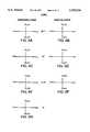
- FIG. 1is a diagrammatic side view of an objective lens system for an endoscope in accordance with a specific embodiment of the invention
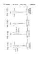
- FIGS. 2(A) to 2(D)are graphs showing characteristic curves of spherical aberrations for C-line, d-line and F-line, characteristic curves of astigmatism in sagittal and tangential image planes, a characteristic curve of distortion, and characteristic curves of lateral chromatic aberration for C-line and F-line, respectively;
- FIG. 3is graphs showing characteristic curves of coma at image heights from the optical axis of approximately 100%, 80% and 60% and on the optical axis in tangential and sagittal image planes for an F number of 5.60;
- FIG. 4is a diagrammatic side view of an objective lens system for an endoscope in accordance with another specific embodiment of the invention.
- FIGS. 5(A) to 5(D)are graphs showing characteristic curves of spherical aberrations for C-line, d-line and F-line, characteristic curves of astigmatism in sagittal and tangential image planes, a characteristic curve of distortion, and characteristic curves of lateral chromatic aberration for C-line and F-line, respectively;
- FIG. 6is graphs showing characteristic curves of coma at image heights from the optical axis of approximately 100%, 80% and 60% and on the optical axis in tangential and sagittal image planes for an F number of 5.60;
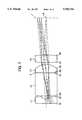
- FIG. 7is a diagrammatic side view of an objective lens system for an endoscope in accordance with still another specific embodiment of the invention.
- FIGS. 8(A) to 8(D)are graphs showing characteristic curves of spherical aberrations for C-line, d-line and F-line, characteristic curves of astigmatism in sagittal and tangential image planes, a characteristic curve of distortion, and characteristic curves of lateral chromatic aberration for C-line and F-line, respectively;
- FIG. 9is graphs showing characteristic curves of coma at image heights from the optical axis of approximately 100%, 80% and 60% and on the optical axis in tangential and sagittal image planes for an F number of 5.60;
- FIG. 10is a diagrammatic side view of an objective lens system for an endoscope in accordance with a further specific embodiment of the invention.
- FIGS. 11(A) to 11(D)are graphs showing characteristic curves of spherical aberrations for C-line, d-line and F-line, characteristic curves of astigmatism in sagittal and tangential image planes, a characteristic curve of distortion, and characteristic curves of lateral chromatic aberration for C-line and F-line, respectively;
- FIG. 12is graphs showing characteristic curves of coma at image heights from the optical axis of approximately 100%, 80% and 60% and on the optical axis in tangential and sagittal image planes for an F number of 5.60;
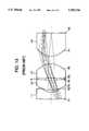
- FIG. 13is a diagrammatic side view of a prior art objective lens system for an endoscope.
- An objective lens system embodying the invention as exemplified in FIGS. 1, 4, 7 and 10is comprised, in order from the subject end to the image end, of a first meniscus lens element of negative optical power having a concave image side surface, a second plano-convex lens element of positive optical power having a convex image side surface, an aperture element, a third plano-convex lens element of positive optical power having a convex image side surface, a fourth biconvex lens element of positive optical power, and an aperture element disposed between the second and third lens elements.
- Bf'designates the back focal length of the objective lens system
- f'designates the overall focal length of the objective lens system
- Ddesignates the value of d 23 +(d 34 /n 2 )+d 4S
- d 23 , d 34 and d 4Sare the axial distance between .the second and third lens surfaces, the third and fourth lens surfaces and the fourth lens surface and the image side surface of the aperture element, respectively
- n 2designates the index of refraction of the second lens element
- R2designates the radius of curvature of the second lens element
- ⁇ 2 , ⁇ 3 and ⁇ 4designate the dispersion as measured by the Abbe number of the second, third and fourth lens elements, respectively.
- the objective lens system OLS1is comprised of, in order from the subject end to the image end, first to fourth optical elements L1-L4.
- the objective lens system OLS1is further comprised of an aperture element S disposed between the second and third lens elements L2 and L3.
- an optical element Psuch as a rectangular prism, for turning the optical axis LX of the objective lens system OLS1 at a right angle.
- the first lens element L1is a negative optical power meniscus lens having a convex subject side surface R1 and a concave image side surface R2.
- the second optical element L2is a positive optical power plano-convex lens having a flat subject side surface R3 and a convex image side surface R4.
- the third optical element L3is a positive optical power plano-convex lens having a flat subject side surface R5 and a convex image side surface R6.
- the fourth optical element L4is a positive optical power biconvex lens having a convex subject side surface R7 and a convex image side surface R8.
- the rectangular prism P having flat subject side and image side surfaces R9 and R10 which practically intersect at a right angleis disposed on the image side of the fourth lens element L4 and turns the optical axis LX at a right angle.
- the aperture element Shas a specified thickness substantially equal to an axial distance between the second and third lens elements L2 and L3 and is held by and between the second and third lens elements L2 and L3.
- the aperture element Smay be formed as a light shield layer coated on an image side surface R6 of the third lens element L3.
- the optical axis LXis depicted as a developed straight line.
- the flat surface R10forms an image plane 1 to which a solid-state imaging element is adhered, or otherwise mechanically contacted.
- the objective lens system OLS1 shown in FIG. 1scaled to an overall focal length (f') of 0.5 mm, an image size of 0.7890 mm in diameter, a subject distance of 3.6698 mm and an angle of view of 91°16' is substantially described in Table I.
- the reference L followed by an arabic numeralindicates the optical element progressively from the subject end to the image end of the lens system OLS1
- ndis the index of refraction of the lens element in relation to d-line
- ⁇ dis the dispersion of the lens element as measured by the Abbe number.
- the reference radius numbers Rare the progressive surface radii. Positive surface radii are struck from the right of the lens surface on the optical axis LX. Negative surface radii are struck from the left of the lens surface on the optical axis LX.
- the objective lens system OLS1 shown in FIG. 1satisfies the conditions (I)-(V).
- FIGS. 2(A)-2(D)show various aberrations, namely spherical aberrations, astigmatism, distortion and lateral chromatic aberrations, respectively, of the objective lens system OLS1 depicted in FIG. 1.
- FIG. 3shows coma of the objective lens system OLS1 depicted in FIG. 1 at image heights from the optical axis of approximately 60, 80 and 100% for an F number of 5.60.
- the objective lens system OLS2is comprised of, in order from the subject end to the image end, first to fourth optical elements L1-L4. Further, the objective lens system OLS2 has an aperture element S disposed between the second and third lens elements L2 and L3.
- the first optical element L1is a negative optical power plano-convex lens having a flat subject side surface R1 and a concave image side surface R2.
- the second optical element L2is a positive optical power plano-convex lens having a convex subject side surface R3 and a flat image side surface R4.
- the third optical element L3is a positive optical power plano-convex lens having a flat subject side surface R5 and a convex image side surface R6.
- the fourth optical element L4is a positive optical power biconvex lens having a convex subject side surface R7 and a convex image side surface R8.
- An image surfaceis designated I, where a solid-state imaging element is disposed.
- the aperture element Shas a specified thickness substantially equal to an axial distance between the second and third lens elements L2 and L3 and is held by and between the second and third lens elements L2 and L3.
- the aperture element Smay be formed as a light shield layer coated on an image side surface R6 of the third lens element L3.
- the objective lens system OLS2 shown in FIG. 1scaled to an overall focal length (f') of 0.5 mm, an image size of 0.91644 mm in diameter, a subject distance of 4.2625 mm and an angle of view of 117030, is substantially described in Table II.
- the objective lens system OLS2 shown in FIG. 4satisfies the conditions (I)-(V).
- FIGS. 5(A)-5(D)show various aberrations, namely spherical aberrations, astigmatism, distortion and lateral chromatic aberrations, respectively, of the objective lens system OLS2 depicted in FIG. 1.
- FIG. 6shows coma of the objective lens system OLS2 depicted in FIG. 1 at image heights from the optical axis of 60, 80 and 100% for an F number of 5.60.
- the objective lens system OLS3is comprised of, in order from the subject end to the image end, first to fourth optical elements L1-L4. Further, the objective lens system OLS3 has an aperture element S disposed between the second and third lens elements L2 and L3.
- the first optical element L1is a negative optical power meniscus lens having a convex subject side surface R1 and a concave image side surface R2.
- the second optical element L2is a positive optical power plano-convex lens having a convex subject side surface R3 and a flat image side surface R4.
- the third optical element L3is a positive optical power plano-convex lens having a flat subject side surface R5 and a convex image side surface R6.
- the fourth optical element L4is a positive optical power biconvex lens having a convex subject side surface R7 and a convex image side surface R8.
- An image surfaceis designated I, where a solid-state imaging element is disposed.
- the aperture element Shas a specified thickness substantially equal to an axial distance between the second and third lens elements L2 and L3 and is held by and between the second and third lens elements L2 and L3.
- the aperture element Smay be formed as a light shield layer coated on an image side surface R6 of the third lens element L3.
- the objective lens system OLS3 shown in FIG. 1scaled to an overall focal length (f') of 0.5 mm, an image size of 0.76348 mm in diameter, a subject distance of 3.5528 mm and an angle of view of 90°54' is substantially described in Table III.
- the objective lens system OLS2 sown in FIG. 7satisfies the conditions (I)-(V).
- FIGS. 8(A)-8(D)show various aberrations, namely spherical aberrations, astigmatism, distortion and lateral chromatic aberrations, respectively, of the objective lens system OLS2 depicted in FIG. 1.
- FIG. 9shows coma of the objective lens system OLS3 depicted in FIG. 1 at image heights from the optical axis of 60, 80 and 100% for an F number of 5.60.
- the objective lens system OLS4is comprised of, in order from the subject end to the image end, first to fourth optical elements L1-L4.
- the objective lens system OLS4is further comprised of an aperture element S disposed between the second and third lens elements L2 and L3.
- an optical element Psuch as a rectangular prism, for turning the optical axis LX of the objective lens system OLS4 at a right angle.
- the first optical element L1is a negative optical power meniscus lens having a convex subject side surface R1 and a concave image side surface R2.
- the second optical element L2is a positive optical power plano-convex lens having a convex subject side surface R3 and a flat image side surface R4.
- the third optical element L3is a positive optical power plano-convex lens having a flat subject side surface R5 and a convex image side surface R6.
- the fourth optical element L4is a positive optical power biconvex lens having a convex subject side surface R7 and a convex image side surface R8.
- the rectangular prism P having flat subject side and image side surfaces R9 and R10 practically intersecting at a right angleis disposed on the image side of the fourth lens element L4 and turns the optical axis LX at a right angle.
- the optical axis LXis depicted as a developed straight line.
- An image plane Iis behind the flat surface R10 of the rectangular prism P, where a solid-state imaging element is located.
- the aperture element Shas a specified thickness substantially equal to an axial distance between the second and third lens elements L2 and L3 and is held by and between the second and third lens elements L2 and L3.
- the aperture element Smay be formed as a light shield layer coated on an image side surface R6 of the third lens element L3.
- the objective lens system OLS4 shown in FIG. 10scaled to an overall focal length (f') of 0.5 mm, an image size of 0.92188 mm in diameter, a subject distance of 4.2878 mm and an angle of view of 119°14' is substantially described in Table IV.
- the objective lens system OLS4 shown in FIG. 10satisfies the conditions (I)-(V).
- FIGS. 11(A)-11(D)show various aberrations, namely spherical aberrations, astigmatism, distortion and lateral chromatic aberrations, respectively, of the objective lens system OLS4 depicted in FIG. 10.
- FIG. 12shows coma of the objective lens system OLS4 depicted in FIG. 10 at image heights from the optical axis of 60, 80 and 100% for an F number of 5.60.
- the significant optical characteristic of the objective lens system for an endoscope of the inventionis made clear in comparison with a comparative prior art objective lens system OLS which is taught by the Japanese Unexamined Patent Publication No. 2(1990)-176611 and shown in FIG. 13.
- the prior art objective lens system OLS for an endoscope described in the Japanese Unexamined Patent Publication No. 2(1990)-176611is comprised, in order from the subject end to the image end, of a first meniscus lens element L1 of negative optical power having a concave image side surface R2, a second meniscus lens element L2 of negative optical power having a concave image side surface R4, a third meniscus lens element L3 of negative optical power having a concave subject side surface R5, a fourth plano-convex lens element L4 of positive optical power having a convex subject side surface R7.
- An aperture element Sis disposed between the second and third lens elements L2 and L3.
- the flat surface R8 of the fourth lens element L4forms an image plane I to which a solid-state imaging element or an image guide fiber bundle at its light entrance end is adhered, or otherwise mechanically contacted.
- the objective lens system OLS shown in FIG. 13scaled to an overall focal length (f') of 0.5 mm, an image size of 0.65381 mm in diameter, a subject distance of 6.0 mm and an angle of view of 90°07' is substantially described in Table V.
- the reference L followed by an arabic numeralindicates the optical element progressively from the subject end to the image end of the lens system OLS
- ndis the index of refraction of the lens element in relation to d-line
- ⁇ dis the dispersion of the lens element as measured by the Abbe number.
- the reference radius numbers Rare the progressive surface radii. Positive surface radii are struck from the right of the lens surface on the optical axis LX. Negative surface radii are struck from the left of the lens surface on the optical axis LX.
- the thickness of the aperture element Sis theoretically taken as zero (0).
- the objective lens system of each of the embodiments of the inventionprovides a sufficiently long back focal length and, consequently, enable to form a space behind the forth lens element in which a rectangular prism for turning the optical axis at a right angle is disposed.
Landscapes
- Physics & Mathematics (AREA)
- General Physics & Mathematics (AREA)
- Optics & Photonics (AREA)
- Astronomy & Astrophysics (AREA)
- Lenses (AREA)
Abstract
Description
Bf'>1.5f' (I)
1.80<D/R2<2.40 (II)
μ.sub.2 >45.0 (Ill)
μ.sub.3 >50.0 (IV)
μ.sub.4 >50.0 (V)
Bf'>1.5f' (I)
1.80<D/R2<2.40 (II)
μ.sub.2 >45.0 (III)
μ.sub.3 >50.0 (IV)
μ.sub.4 >50.0 (V)
TABLE I ______________________________________ Radius of Axial distance Element Curvature Between Surfaces nd νd ______________________________________ R1 = 2.8333 L1 0.2141 1.83500 42.6 R2 = 0.3576 0.1224 R3 = 2.8359 L2 0.9461 1.80518 25.4 R4 = ∞ S 0.0306 R5 = ∞ L3 0.3670 1.69680 55.6 R6 = -0.6338 0.0314 R7 = 2.3497 L4 0.3670 1.69680 55.6 R8 = -6.5207 0.3000 R9 = ∞ P 1.2000 1.55920 53.9 R10 = ∞ ______________________________________ Bf' = 2.00 f'- D/R2 = 0.1224 + (0.9461/1.80518) + 0.0306!/0.3576 = 1.893
TABLE II ______________________________________ Radius of Axial distance Element Curvature Between Surfaces nd νd ______________________________________ R1 = ∞ L1 0.2486 1.83500 42.6 R2 = 0.3816 0.1422 R3 = 3.3087 L2 1.0044 1.80518 25.4 R4 = ∞ S 0.0355 R5 = ∞ L3 0.4263 1.69680 55.6 R6 = -0.7028 0.0711 R7 = 2.3647 L4 0.4263 1.69680 55.6 R8 = -9.3143 ______________________________________ Bf' = 2.360f'- D/R2 = 0.1422 + (1.0044/1.80518) + 0.0355!/0.3816 = 1.924
TABLE III ______________________________________ Radius of Axial distance Element Curvature Between Surfaces nd νd ______________________________________ R1 = 11.9586 L1 0.2072 1.88300 41.0 R2 = 0.3380 0.1189 R3 = 4.1222 L2 0.9816 1.80518 25.4 R4 = ∞ S 0.0296 R5 = ∞ L3 0.3558 1.69680 55.6 R6 = -0.6681 0.0602 R7 = 2.8365 L4 0.3560 1.62041 60.3 R8 = -4.0220 ______________________________________ Bf' = 2.660f'- D/R2 = 0.1189 + (0.9816/1.80518) + 0.0296!/0.3380 = 2.048
TABLE IV ______________________________________ Radius of Axial distance Element Curvature Between Surfaces nd νd ______________________________________ R1 = 19.2005 L1 0.2501 1.88300 41.0 R2 = 0.3785 0.2302 R3 = 111.4488 L2 1.0768 1.80518 25.4 R4 = ∞ S 0.0357 R5 = ∞ L3 0.4623 1.69680 55.6 R6 = -0.7769 0.0948 R7 = 3.2396 L4 0.4535 1.69680 55.6 R8 = -6.6209 0.5000 R9 = ∞ P 1.5000 1.55920 53.9 R10 = ∞ ______________________________________ Bf' = 3.030f'- D/R2 = 0.2300 + (1.0768/1.80518) + 0.0357!/0.3785 = 2.278
TABLE V ______________________________________ Radius of Axial distance Element Curvature Between Surfaces nd νd ______________________________________ R1 = 7.505 L1 0.296 1.72916 54.8 R2 = 0.548 0.099 R3 = 0.921 L2 0.494 1.66755 41.9 R4 = 11.727 0.033 S -- 0.033 R5 = ∞ L3 0.657 1.72916 54.8 R6 = -11.727 0.281 R7 = 3.2396 L4 1.016 1.60738 56.7 R8 = ∞ ______________________________________ Bf' = 0.000f'- D/R2 = 0.099 + (0.494/1.66755) + 0.033!/0.548 = 0.781
Claims (17)
______________________________________ Radius of Axial distance Element Curvature Between Surfaces nd νd ______________________________________ R1 = 2.8333 L1 0.2141 1.83500 42.6 R2 = 0.3576 0.1224 R3 = 2.8359 L2 0.9461 1.80518 25.4 R4 = ∞ S 0.0306 R5 = ∞ L3 0.3670 1.69680 55.6 R6 = -0.6338 0.0314 R7 = 2.3497 L4 0.3670 1.69680 55.6 R8 = -6.5207 ______________________________________
______________________________________ Radius of Axial distance Element Curvature Between Surfaces nd νd ______________________________________ R1 = ∞ L1 0.2486 1.83500 42.6 R2 = 0.3816 0.1422 R3 = 3.3087 L2 1.0044 1.80518 25.4 R4 = ∞ S 0.0355 R5 = ∞ L3 0.4263 1.69680 55.6 R6 = -0.7028 0.0711 R7 = 2.3647 L4 0.4263 1.69680 55.6 R8 = -9.3143 ______________________________________
______________________________________ Radius of Axial distance Element Curvature Between Surfaces nd νd ______________________________________ R1 = 11.9586 L1 0.2072 1.88300 41.0 R2 = 0.3380 0.1189 R3 = 4.1222 L2 0.9816 1.80518 25.4 R4 = ∞ S 0.0296 R5 = ∞ L3 0.3558 1.69680 55.6 R6 = -0.6681 0.0602 R7 = 2.8365 L4 0.3560 1.62041 60.3 R8 = -4.0220 ______________________________________
______________________________________ Radius of Axial distance Element Curvature Between Surfaces nd νd ______________________________________ R1 = 19.2005 L1 0.2501 1.88300 41.0 R2 = 0.3785 0.2302 R3 = 111.4488 L2 1.0768 1.80518 25.4 R4 = ∞ S 0.0357 R5 = ∞ L3 0.4623 1.69680 55.6 R6 = -0.7769 0.0948 R7 = 3.2396 L4 0.4535 1.69680 55.6 R8 = -6.6209 ______________________________________
Applications Claiming Priority (2)
| Application Number | Priority Date | Filing Date | Title |
|---|---|---|---|
| JP11720495AJP3429602B2 (en) | 1995-04-05 | 1995-05-16 | Objective lens for endoscope |
| JP7-117204 | 1995-05-16 |
Publications (1)
| Publication Number | Publication Date |
|---|---|
| US5703724Atrue US5703724A (en) | 1997-12-30 |
Family
ID=14705970
Family Applications (1)
| Application Number | Title | Priority Date | Filing Date |
|---|---|---|---|
| US08/653,599Expired - Fee RelatedUS5703724A (en) | 1995-05-16 | 1996-05-16 | Objective lens system for endoscope |
Country Status (1)
| Country | Link |
|---|---|
| US (1) | US5703724A (en) |
Cited By (29)
| Publication number | Priority date | Publication date | Assignee | Title |
|---|---|---|---|---|
| RU2183029C2 (en)* | 1997-06-16 | 2002-05-27 | Открытое акционерное общество "ЛОМО" | Inlet part of endoscope |
| US6682478B2 (en)* | 2001-02-08 | 2004-01-27 | Olympus Optical Co., Ltd. | Endoscope apparatus with an insertion part having a small outer diameter which includes and object optical system |
| US20060221457A1 (en)* | 2005-03-30 | 2006-10-05 | Pentax Corporation | Endoscope objective lens system |
| US7241263B2 (en) | 2004-09-30 | 2007-07-10 | Scimed Life Systems, Inc. | Selectively rotatable shaft coupler |
| US20080181601A1 (en)* | 2007-01-30 | 2008-07-31 | Dai Shintani | Optical part, lens barrel, and camera |
| US7413543B2 (en) | 2003-04-01 | 2008-08-19 | Scimed Life Systems, Inc. | Endoscope with actively cooled illumination sources |
| US7479106B2 (en) | 2004-09-30 | 2009-01-20 | Boston Scientific Scimed, Inc. | Automated control of irrigation and aspiration in a single-use endoscope |
| US7578786B2 (en) | 2003-04-01 | 2009-08-25 | Boston Scientific Scimed, Inc. | Video endoscope |
| US7591783B2 (en) | 2003-04-01 | 2009-09-22 | Boston Scientific Scimed, Inc. | Articulation joint for video endoscope |
| US7597662B2 (en) | 2004-09-30 | 2009-10-06 | Boston Scientific Scimed, Inc. | Multi-fluid delivery system |
| US20100261958A1 (en)* | 2007-11-12 | 2010-10-14 | Cornell University | Multi-path, multi-magnification, non-confocal fluorescence emission endoscopy apparatus and methods |
| US20100270479A1 (en)* | 2007-11-12 | 2010-10-28 | Cornell University | Non-imaging, weakly focused fluorescence emission apparatus and method |
| US7846107B2 (en) | 2005-05-13 | 2010-12-07 | Boston Scientific Scimed, Inc. | Endoscopic apparatus with integrated multiple biopsy device |
| US7955255B2 (en) | 2006-04-20 | 2011-06-07 | Boston Scientific Scimed, Inc. | Imaging assembly with transparent distal cap |
| US7967759B2 (en) | 2006-01-19 | 2011-06-28 | Boston Scientific Scimed, Inc. | Endoscopic system with integrated patient respiratory status indicator |
| US8052597B2 (en) | 2005-08-30 | 2011-11-08 | Boston Scientific Scimed, Inc. | Method for forming an endoscope articulation joint |
| US8083671B2 (en) | 2004-09-30 | 2011-12-27 | Boston Scientific Scimed, Inc. | Fluid delivery system for use with an endoscope |
| US8097003B2 (en) | 2005-05-13 | 2012-01-17 | Boston Scientific Scimed, Inc. | Endoscopic apparatus with integrated variceal ligation device |
| US8118732B2 (en) | 2003-04-01 | 2012-02-21 | Boston Scientific Scimed, Inc. | Force feedback control system for video endoscope |
| US8199187B2 (en) | 2004-09-30 | 2012-06-12 | Boston Scientific Scimed, Inc. | Adapter for use with digital imaging medical device |
| US8202265B2 (en) | 2006-04-20 | 2012-06-19 | Boston Scientific Scimed, Inc. | Multiple lumen assembly for use in endoscopes or other medical devices |
| US8353860B2 (en) | 2004-09-30 | 2013-01-15 | Boston Scientific Scimed, Inc. | Device for obstruction removal with specific tip structure |
| US8357148B2 (en) | 2004-09-30 | 2013-01-22 | Boston Scientific Scimed, Inc. | Multi-functional endoscopic system for use in electrosurgical applications |
| CN102958420A (en)* | 2010-07-02 | 2013-03-06 | 直观外科手术操作公司 | Dual optical path prism and camera in minimally invasive surgery system |
| US8535219B2 (en) | 2003-04-01 | 2013-09-17 | Boston Scientific Scimed, Inc. | Fluid manifold for endoscope system |
| US20140043592A1 (en)* | 2003-08-26 | 2014-02-13 | Nikon Corporation | Optical element and exposure apparatus |
| US8888684B2 (en) | 2006-03-27 | 2014-11-18 | Boston Scientific Scimed, Inc. | Medical devices with local drug delivery capabilities |
| US20170071449A1 (en)* | 2014-09-22 | 2017-03-16 | Olympus Corporation | Endoscope objective optical system |
| US20230273405A1 (en)* | 2022-02-25 | 2023-08-31 | Genius Electronic Optical (Xiamen) Co., Ltd. | Optical imaging lens |
Citations (5)
| Publication number | Priority date | Publication date | Assignee | Title |
|---|---|---|---|---|
| US4493537A (en)* | 1981-11-10 | 1985-01-15 | Olympus Optical Co., Ltd. | Objective lens system for endoscopes |
| JPH02176611A (en)* | 1988-09-29 | 1990-07-09 | Fuji Photo Optical Co Ltd | Objective lens for endoscope |
| US5175650A (en)* | 1989-05-09 | 1992-12-29 | Olympus Optical Co., Ltd. | Objective lens system for endoscopes |
| US5198931A (en)* | 1989-04-19 | 1993-03-30 | Olympus Optical Co., Ltd. | Objective optical system for endoscopes |
| US5587839A (en)* | 1994-10-18 | 1996-12-24 | Fuji Photo Optical Co., Ltd. | Objective lens system for endoscope |
- 1996
- 1996-05-16USUS08/653,599patent/US5703724A/ennot_activeExpired - Fee Related
Patent Citations (6)
| Publication number | Priority date | Publication date | Assignee | Title |
|---|---|---|---|---|
| US4493537A (en)* | 1981-11-10 | 1985-01-15 | Olympus Optical Co., Ltd. | Objective lens system for endoscopes |
| JPH02176611A (en)* | 1988-09-29 | 1990-07-09 | Fuji Photo Optical Co Ltd | Objective lens for endoscope |
| US4984878A (en)* | 1988-09-29 | 1991-01-15 | Fuji Photo Optical Co., Ltd. | Ojective lens for endoscope |
| US5198931A (en)* | 1989-04-19 | 1993-03-30 | Olympus Optical Co., Ltd. | Objective optical system for endoscopes |
| US5175650A (en)* | 1989-05-09 | 1992-12-29 | Olympus Optical Co., Ltd. | Objective lens system for endoscopes |
| US5587839A (en)* | 1994-10-18 | 1996-12-24 | Fuji Photo Optical Co., Ltd. | Objective lens system for endoscope |
Cited By (53)
| Publication number | Priority date | Publication date | Assignee | Title |
|---|---|---|---|---|
| RU2183029C2 (en)* | 1997-06-16 | 2002-05-27 | Открытое акционерное общество "ЛОМО" | Inlet part of endoscope |
| US6682478B2 (en)* | 2001-02-08 | 2004-01-27 | Olympus Optical Co., Ltd. | Endoscope apparatus with an insertion part having a small outer diameter which includes and object optical system |
| US8425408B2 (en) | 2003-04-01 | 2013-04-23 | Boston Scientific Scimed, Inc. | Articulation joint for video endoscope |
| US7591783B2 (en) | 2003-04-01 | 2009-09-22 | Boston Scientific Scimed, Inc. | Articulation joint for video endoscope |
| US8535219B2 (en) | 2003-04-01 | 2013-09-17 | Boston Scientific Scimed, Inc. | Fluid manifold for endoscope system |
| US8622894B2 (en) | 2003-04-01 | 2014-01-07 | Boston Scientific Scimed, Inc. | Articulation joint |
| US7413543B2 (en) | 2003-04-01 | 2008-08-19 | Scimed Life Systems, Inc. | Endoscope with actively cooled illumination sources |
| US8608648B2 (en) | 2003-04-01 | 2013-12-17 | Boston Scientific Scimed, Inc. | Articulation joint |
| US7578786B2 (en) | 2003-04-01 | 2009-08-25 | Boston Scientific Scimed, Inc. | Video endoscope |
| US10765307B2 (en) | 2003-04-01 | 2020-09-08 | Boston Scientific Scimed, Inc. | Endoscopic imaging system |
| US9913573B2 (en) | 2003-04-01 | 2018-03-13 | Boston Scientific Scimed, Inc. | Endoscopic imaging system |
| US11324395B2 (en) | 2003-04-01 | 2022-05-10 | Boston Scientific Scimed, Inc. | Endoscopic imaging system |
| US8118732B2 (en) | 2003-04-01 | 2012-02-21 | Boston Scientific Scimed, Inc. | Force feedback control system for video endoscope |
| US8475366B2 (en) | 2003-04-01 | 2013-07-02 | Boston Scientific Scimed, Inc. | Articulation joint for a medical device |
| US10175584B2 (en)* | 2003-08-26 | 2019-01-08 | Nikon Corporation | Optical element and exposure apparatus |
| US20140043592A1 (en)* | 2003-08-26 | 2014-02-13 | Nikon Corporation | Optical element and exposure apparatus |
| US7241263B2 (en) | 2004-09-30 | 2007-07-10 | Scimed Life Systems, Inc. | Selectively rotatable shaft coupler |
| USRE46007E1 (en) | 2004-09-30 | 2016-05-24 | Boston Scientific Scimed, Inc. | Automated control of irrigation and aspiration in a single-use endoscope |
| US7479106B2 (en) | 2004-09-30 | 2009-01-20 | Boston Scientific Scimed, Inc. | Automated control of irrigation and aspiration in a single-use endoscope |
| US8083671B2 (en) | 2004-09-30 | 2011-12-27 | Boston Scientific Scimed, Inc. | Fluid delivery system for use with an endoscope |
| US7597662B2 (en) | 2004-09-30 | 2009-10-06 | Boston Scientific Scimed, Inc. | Multi-fluid delivery system |
| US8197400B2 (en) | 2004-09-30 | 2012-06-12 | Boston Scientific Scimed, Inc. | Selectively rotatable shaft coupler |
| US8199187B2 (en) | 2004-09-30 | 2012-06-12 | Boston Scientific Scimed, Inc. | Adapter for use with digital imaging medical device |
| US8435172B2 (en) | 2004-09-30 | 2013-05-07 | Boston Scientific Scimed, Inc. | Automated control of irrigation and aspiration in a single-use endoscope |
| US8353860B2 (en) | 2004-09-30 | 2013-01-15 | Boston Scientific Scimed, Inc. | Device for obstruction removal with specific tip structure |
| US8357148B2 (en) | 2004-09-30 | 2013-01-22 | Boston Scientific Scimed, Inc. | Multi-functional endoscopic system for use in electrosurgical applications |
| US20060221457A1 (en)* | 2005-03-30 | 2006-10-05 | Pentax Corporation | Endoscope objective lens system |
| US7379252B2 (en) | 2005-03-30 | 2008-05-27 | Pentax Corporation | Endoscope objective lens system |
| US7846107B2 (en) | 2005-05-13 | 2010-12-07 | Boston Scientific Scimed, Inc. | Endoscopic apparatus with integrated multiple biopsy device |
| US8585715B2 (en) | 2005-05-13 | 2013-11-19 | Boston Scientific Scimed, Inc. | Endoscopic apparatus with integrated variceal ligation device |
| US8097003B2 (en) | 2005-05-13 | 2012-01-17 | Boston Scientific Scimed, Inc. | Endoscopic apparatus with integrated variceal ligation device |
| US10052013B2 (en) | 2005-08-30 | 2018-08-21 | Boston Scientific Scimed, Inc. | Medical device comprising segments |
| US8052597B2 (en) | 2005-08-30 | 2011-11-08 | Boston Scientific Scimed, Inc. | Method for forming an endoscope articulation joint |
| US11191424B2 (en) | 2005-08-30 | 2021-12-07 | Boston Scientific Scimed, Inc. | Method for forming an endoscope articulation joint |
| US11957312B2 (en) | 2005-08-30 | 2024-04-16 | Boston Scientific Scimed, Inc. | Method for forming an endoscope articulation joint |
| US9439557B2 (en) | 2005-08-30 | 2016-09-13 | Boston Scientific Scimed, Inc. | Articulation joint |
| US7967759B2 (en) | 2006-01-19 | 2011-06-28 | Boston Scientific Scimed, Inc. | Endoscopic system with integrated patient respiratory status indicator |
| US8888684B2 (en) | 2006-03-27 | 2014-11-18 | Boston Scientific Scimed, Inc. | Medical devices with local drug delivery capabilities |
| US7955255B2 (en) | 2006-04-20 | 2011-06-07 | Boston Scientific Scimed, Inc. | Imaging assembly with transparent distal cap |
| US9358363B2 (en) | 2006-04-20 | 2016-06-07 | Boston Scientific Scimed, Inc. | Multiple lumen assembly for use in endoscopes or other medical devices |
| US8870753B2 (en) | 2006-04-20 | 2014-10-28 | Boston Scientific Scimed, Inc. | Imaging assembly with transparent distal cap |
| US8202265B2 (en) | 2006-04-20 | 2012-06-19 | Boston Scientific Scimed, Inc. | Multiple lumen assembly for use in endoscopes or other medical devices |
| US8031412B2 (en)* | 2007-01-30 | 2011-10-04 | Panasonic Corporation | Optical part, lens barrel, and camera |
| US20080181601A1 (en)* | 2007-01-30 | 2008-07-31 | Dai Shintani | Optical part, lens barrel, and camera |
| US20100261958A1 (en)* | 2007-11-12 | 2010-10-14 | Cornell University | Multi-path, multi-magnification, non-confocal fluorescence emission endoscopy apparatus and methods |
| US8553337B2 (en) | 2007-11-12 | 2013-10-08 | Cornell University | Multi-path, multi-magnification, non-confocal fluorescence emission endoscopy apparatus and methods |
| US20100270479A1 (en)* | 2007-11-12 | 2010-10-28 | Cornell University | Non-imaging, weakly focused fluorescence emission apparatus and method |
| CN102958420A (en)* | 2010-07-02 | 2013-03-06 | 直观外科手术操作公司 | Dual optical path prism and camera in minimally invasive surgery system |
| CN102958420B (en)* | 2010-07-02 | 2016-01-20 | 直观外科手术操作公司 | Dual optical path prism and camera in minimally invasive surgery system |
| US9817226B2 (en)* | 2014-09-22 | 2017-11-14 | Olympus Corporation | Endoscope objective optical system |
| US20170071449A1 (en)* | 2014-09-22 | 2017-03-16 | Olympus Corporation | Endoscope objective optical system |
| US20230273405A1 (en)* | 2022-02-25 | 2023-08-31 | Genius Electronic Optical (Xiamen) Co., Ltd. | Optical imaging lens |
| US12242030B2 (en)* | 2022-02-25 | 2025-03-04 | Genius Electronic Optical (Xiamen) Co., Ltd. | Optical imaging lens |
Similar Documents
| Publication | Publication Date | Title |
|---|---|---|
| US5703724A (en) | Objective lens system for endoscope | |
| US5777797A (en) | Objective lens system for endoscopes having an image transfer optical fiber bundle | |
| US4877314A (en) | Objective lens system for endoscopes | |
| US4984878A (en) | Ojective lens for endoscope | |
| US4403837A (en) | Objective for endoscopes | |
| US5619380A (en) | Objective optical system for endoscopes | |
| US4676606A (en) | Image transmission optical system for an endoscope | |
| JPH0836124A (en) | Lens holding device and lens system including the device | |
| US4394073A (en) | Compact wide angle lens | |
| US6317271B1 (en) | Zoom lens system | |
| JP3206930B2 (en) | Endoscope objective lens | |
| US5175652A (en) | Imaging optical system | |
| US5969873A (en) | Eyepiece lens with image located in space between first and second lens units | |
| US5166828A (en) | Zoom lens system | |
| US4208099A (en) | Microscope objective lens system | |
| US4448497A (en) | Great aperture ratio lens | |
| US6166861A (en) | Wide-angle eyepiece lens | |
| US4364641A (en) | Wide angle zoom lens | |
| US5438455A (en) | Internal focus telephoto lens for an auto focus camera | |
| JP3429602B2 (en) | Objective lens for endoscope | |
| JPS6148685B2 (en) | ||
| JPH1184239A (en) | Zoom lens | |
| US5515208A (en) | Endoscope objective lens | |
| JP3540349B2 (en) | Wide angle lens with long back focus | |
| US4348085A (en) | Inverted telephoto type wide angle lens |
Legal Events
| Date | Code | Title | Description |
|---|---|---|---|
| AS | Assignment | Owner name:FUJI PHOTO OPTICAL CO., LTD., JAPAN Free format text:ASSIGNMENT OF ASSIGNORS INTEREST;ASSIGNOR:MIYANO, HITOSHI;REEL/FRAME:008076/0496 Effective date:19960605 Owner name:FUJI PHOTO FILM CO., LTD., JAPAN Free format text:ASSIGNMENT OF ASSIGNORS INTEREST;ASSIGNOR:MIYANO, HITOSHI;REEL/FRAME:008076/0496 Effective date:19960605 | |
| FPAY | Fee payment | Year of fee payment:4 | |
| FPAY | Fee payment | Year of fee payment:8 | |
| AS | Assignment | Owner name:FUJINON CORPORATION, JAPAN Free format text:CHANGE OF NAME;ASSIGNOR:FUJI PHOTO OPTICAL CO., LTD.;REEL/FRAME:016712/0700 Effective date:20041001 | |
| AS | Assignment | Owner name:FUJIFILM CORPORATION, JAPAN Free format text:ASSIGNMENT OF ASSIGNORS INTEREST;ASSIGNOR:FUJIFILM HOLDINGS CORPORATION (FORMERLY FUJI PHOTO FILM CO., LTD.);REEL/FRAME:019094/0411 Effective date:20070320 | |
| REMI | Maintenance fee reminder mailed | ||
| LAPS | Lapse for failure to pay maintenance fees | ||
| STCH | Information on status: patent discontinuation | Free format text:PATENT EXPIRED DUE TO NONPAYMENT OF MAINTENANCE FEES UNDER 37 CFR 1.362 | |
| FP | Lapsed due to failure to pay maintenance fee | Effective date:20091230 |