US5703461A - Inductive coupler for electric vehicle charger - Google Patents
Inductive coupler for electric vehicle chargerDownload PDFInfo
- Publication number
- US5703461A US5703461AUS08/671,218US67121896AUS5703461AUS 5703461 AUS5703461 AUS 5703461AUS 67121896 AUS67121896 AUS 67121896AUS 5703461 AUS5703461 AUS 5703461A
- Authority
- US
- United States
- Prior art keywords
- primary
- vehicle
- coil
- coils
- inductive coupler
- Prior art date
- Legal status (The legal status is an assumption and is not a legal conclusion. Google has not performed a legal analysis and makes no representation as to the accuracy of the status listed.)
- Expired - Fee Related
Links
- 230000001939inductive effectEffects0.000titleclaimsabstractdescription45
- 230000008878couplingEffects0.000claimsdescription13
- 238000010168coupling processMethods0.000claimsdescription13
- 238000005859coupling reactionMethods0.000claimsdescription13
- 230000004048modificationEffects0.000description6
- 238000012986modificationMethods0.000description6
- 239000000696magnetic materialSubstances0.000description5
- 230000005674electromagnetic inductionEffects0.000description2
- 230000003028elevating effectEffects0.000description2
- 238000005452bendingMethods0.000description1
- 230000000694effectsEffects0.000description1
- 230000002452interceptive effectEffects0.000description1
- 238000000034methodMethods0.000description1
Images


Classifications
- H—ELECTRICITY
- H01—ELECTRIC ELEMENTS
- H01F—MAGNETS; INDUCTANCES; TRANSFORMERS; SELECTION OF MATERIALS FOR THEIR MAGNETIC PROPERTIES
- H01F38/00—Adaptations of transformers or inductances for specific applications or functions
- H01F38/14—Inductive couplings
- B—PERFORMING OPERATIONS; TRANSPORTING
- B60—VEHICLES IN GENERAL
- B60L—PROPULSION OF ELECTRICALLY-PROPELLED VEHICLES; SUPPLYING ELECTRIC POWER FOR AUXILIARY EQUIPMENT OF ELECTRICALLY-PROPELLED VEHICLES; ELECTRODYNAMIC BRAKE SYSTEMS FOR VEHICLES IN GENERAL; MAGNETIC SUSPENSION OR LEVITATION FOR VEHICLES; MONITORING OPERATING VARIABLES OF ELECTRICALLY-PROPELLED VEHICLES; ELECTRIC SAFETY DEVICES FOR ELECTRICALLY-PROPELLED VEHICLES
- B60L53/00—Methods of charging batteries, specially adapted for electric vehicles; Charging stations or on-board charging equipment therefor; Exchange of energy storage elements in electric vehicles
- B60L53/10—Methods of charging batteries, specially adapted for electric vehicles; Charging stations or on-board charging equipment therefor; Exchange of energy storage elements in electric vehicles characterised by the energy transfer between the charging station and the vehicle
- B60L53/12—Inductive energy transfer
- B60L53/126—Methods for pairing a vehicle and a charging station, e.g. establishing a one-to-one relation between a wireless power transmitter and a wireless power receiver
- B—PERFORMING OPERATIONS; TRANSPORTING
- B60—VEHICLES IN GENERAL
- B60L—PROPULSION OF ELECTRICALLY-PROPELLED VEHICLES; SUPPLYING ELECTRIC POWER FOR AUXILIARY EQUIPMENT OF ELECTRICALLY-PROPELLED VEHICLES; ELECTRODYNAMIC BRAKE SYSTEMS FOR VEHICLES IN GENERAL; MAGNETIC SUSPENSION OR LEVITATION FOR VEHICLES; MONITORING OPERATING VARIABLES OF ELECTRICALLY-PROPELLED VEHICLES; ELECTRIC SAFETY DEVICES FOR ELECTRICALLY-PROPELLED VEHICLES
- B60L53/00—Methods of charging batteries, specially adapted for electric vehicles; Charging stations or on-board charging equipment therefor; Exchange of energy storage elements in electric vehicles
- B60L53/30—Constructional details of charging stations
- B60L53/31—Charging columns specially adapted for electric vehicles
- B—PERFORMING OPERATIONS; TRANSPORTING
- B60—VEHICLES IN GENERAL
- B60L—PROPULSION OF ELECTRICALLY-PROPELLED VEHICLES; SUPPLYING ELECTRIC POWER FOR AUXILIARY EQUIPMENT OF ELECTRICALLY-PROPELLED VEHICLES; ELECTRODYNAMIC BRAKE SYSTEMS FOR VEHICLES IN GENERAL; MAGNETIC SUSPENSION OR LEVITATION FOR VEHICLES; MONITORING OPERATING VARIABLES OF ELECTRICALLY-PROPELLED VEHICLES; ELECTRIC SAFETY DEVICES FOR ELECTRICALLY-PROPELLED VEHICLES
- B60L53/00—Methods of charging batteries, specially adapted for electric vehicles; Charging stations or on-board charging equipment therefor; Exchange of energy storage elements in electric vehicles
- B60L53/30—Constructional details of charging stations
- B60L53/35—Means for automatic or assisted adjustment of the relative position of charging devices and vehicles
- B60L53/36—Means for automatic or assisted adjustment of the relative position of charging devices and vehicles by positioning the vehicle
- B—PERFORMING OPERATIONS; TRANSPORTING
- B60—VEHICLES IN GENERAL
- B60L—PROPULSION OF ELECTRICALLY-PROPELLED VEHICLES; SUPPLYING ELECTRIC POWER FOR AUXILIARY EQUIPMENT OF ELECTRICALLY-PROPELLED VEHICLES; ELECTRODYNAMIC BRAKE SYSTEMS FOR VEHICLES IN GENERAL; MAGNETIC SUSPENSION OR LEVITATION FOR VEHICLES; MONITORING OPERATING VARIABLES OF ELECTRICALLY-PROPELLED VEHICLES; ELECTRIC SAFETY DEVICES FOR ELECTRICALLY-PROPELLED VEHICLES
- B60L53/00—Methods of charging batteries, specially adapted for electric vehicles; Charging stations or on-board charging equipment therefor; Exchange of energy storage elements in electric vehicles
- B60L53/30—Constructional details of charging stations
- B60L53/35—Means for automatic or assisted adjustment of the relative position of charging devices and vehicles
- B60L53/37—Means for automatic or assisted adjustment of the relative position of charging devices and vehicles using optical position determination, e.g. using cameras
- B—PERFORMING OPERATIONS; TRANSPORTING
- B60—VEHICLES IN GENERAL
- B60L—PROPULSION OF ELECTRICALLY-PROPELLED VEHICLES; SUPPLYING ELECTRIC POWER FOR AUXILIARY EQUIPMENT OF ELECTRICALLY-PROPELLED VEHICLES; ELECTRODYNAMIC BRAKE SYSTEMS FOR VEHICLES IN GENERAL; MAGNETIC SUSPENSION OR LEVITATION FOR VEHICLES; MONITORING OPERATING VARIABLES OF ELECTRICALLY-PROPELLED VEHICLES; ELECTRIC SAFETY DEVICES FOR ELECTRICALLY-PROPELLED VEHICLES
- B60L53/00—Methods of charging batteries, specially adapted for electric vehicles; Charging stations or on-board charging equipment therefor; Exchange of energy storage elements in electric vehicles
- B60L53/30—Constructional details of charging stations
- B60L53/35—Means for automatic or assisted adjustment of the relative position of charging devices and vehicles
- B60L53/38—Means for automatic or assisted adjustment of the relative position of charging devices and vehicles specially adapted for charging by inductive energy transfer
- B—PERFORMING OPERATIONS; TRANSPORTING
- B60—VEHICLES IN GENERAL
- B60L—PROPULSION OF ELECTRICALLY-PROPELLED VEHICLES; SUPPLYING ELECTRIC POWER FOR AUXILIARY EQUIPMENT OF ELECTRICALLY-PROPELLED VEHICLES; ELECTRODYNAMIC BRAKE SYSTEMS FOR VEHICLES IN GENERAL; MAGNETIC SUSPENSION OR LEVITATION FOR VEHICLES; MONITORING OPERATING VARIABLES OF ELECTRICALLY-PROPELLED VEHICLES; ELECTRIC SAFETY DEVICES FOR ELECTRICALLY-PROPELLED VEHICLES
- B60L2210/00—Converter types
- B60L2210/30—AC to DC converters
- Y—GENERAL TAGGING OF NEW TECHNOLOGICAL DEVELOPMENTS; GENERAL TAGGING OF CROSS-SECTIONAL TECHNOLOGIES SPANNING OVER SEVERAL SECTIONS OF THE IPC; TECHNICAL SUBJECTS COVERED BY FORMER USPC CROSS-REFERENCE ART COLLECTIONS [XRACs] AND DIGESTS
- Y02—TECHNOLOGIES OR APPLICATIONS FOR MITIGATION OR ADAPTATION AGAINST CLIMATE CHANGE
- Y02T—CLIMATE CHANGE MITIGATION TECHNOLOGIES RELATED TO TRANSPORTATION
- Y02T10/00—Road transport of goods or passengers
- Y02T10/60—Other road transportation technologies with climate change mitigation effect
- Y02T10/70—Energy storage systems for electromobility, e.g. batteries
- Y—GENERAL TAGGING OF NEW TECHNOLOGICAL DEVELOPMENTS; GENERAL TAGGING OF CROSS-SECTIONAL TECHNOLOGIES SPANNING OVER SEVERAL SECTIONS OF THE IPC; TECHNICAL SUBJECTS COVERED BY FORMER USPC CROSS-REFERENCE ART COLLECTIONS [XRACs] AND DIGESTS
- Y02—TECHNOLOGIES OR APPLICATIONS FOR MITIGATION OR ADAPTATION AGAINST CLIMATE CHANGE
- Y02T—CLIMATE CHANGE MITIGATION TECHNOLOGIES RELATED TO TRANSPORTATION
- Y02T10/00—Road transport of goods or passengers
- Y02T10/60—Other road transportation technologies with climate change mitigation effect
- Y02T10/7072—Electromobility specific charging systems or methods for batteries, ultracapacitors, supercapacitors or double-layer capacitors
- Y—GENERAL TAGGING OF NEW TECHNOLOGICAL DEVELOPMENTS; GENERAL TAGGING OF CROSS-SECTIONAL TECHNOLOGIES SPANNING OVER SEVERAL SECTIONS OF THE IPC; TECHNICAL SUBJECTS COVERED BY FORMER USPC CROSS-REFERENCE ART COLLECTIONS [XRACs] AND DIGESTS
- Y02—TECHNOLOGIES OR APPLICATIONS FOR MITIGATION OR ADAPTATION AGAINST CLIMATE CHANGE
- Y02T—CLIMATE CHANGE MITIGATION TECHNOLOGIES RELATED TO TRANSPORTATION
- Y02T10/00—Road transport of goods or passengers
- Y02T10/60—Other road transportation technologies with climate change mitigation effect
- Y02T10/72—Electric energy management in electromobility
- Y—GENERAL TAGGING OF NEW TECHNOLOGICAL DEVELOPMENTS; GENERAL TAGGING OF CROSS-SECTIONAL TECHNOLOGIES SPANNING OVER SEVERAL SECTIONS OF THE IPC; TECHNICAL SUBJECTS COVERED BY FORMER USPC CROSS-REFERENCE ART COLLECTIONS [XRACs] AND DIGESTS
- Y02—TECHNOLOGIES OR APPLICATIONS FOR MITIGATION OR ADAPTATION AGAINST CLIMATE CHANGE
- Y02T—CLIMATE CHANGE MITIGATION TECHNOLOGIES RELATED TO TRANSPORTATION
- Y02T90/00—Enabling technologies or technologies with a potential or indirect contribution to GHG emissions mitigation
- Y02T90/10—Technologies relating to charging of electric vehicles
- Y02T90/12—Electric charging stations
- Y—GENERAL TAGGING OF NEW TECHNOLOGICAL DEVELOPMENTS; GENERAL TAGGING OF CROSS-SECTIONAL TECHNOLOGIES SPANNING OVER SEVERAL SECTIONS OF THE IPC; TECHNICAL SUBJECTS COVERED BY FORMER USPC CROSS-REFERENCE ART COLLECTIONS [XRACs] AND DIGESTS
- Y02—TECHNOLOGIES OR APPLICATIONS FOR MITIGATION OR ADAPTATION AGAINST CLIMATE CHANGE
- Y02T—CLIMATE CHANGE MITIGATION TECHNOLOGIES RELATED TO TRANSPORTATION
- Y02T90/00—Enabling technologies or technologies with a potential or indirect contribution to GHG emissions mitigation
- Y02T90/10—Technologies relating to charging of electric vehicles
- Y02T90/14—Plug-in electric vehicles
Definitions
- the present inventionrelates generally to an apparatus for charging a battery of an electric vehicle, and more specifically to an inductive coupler for use in such battery charging apparatus.
- a battery charging system for electric vehiclesplays a key role for utilization of such vehicles and, therefore, the ease of handling the charging system helps to make the electric vehicles acceptable to the market and more popular among the prospective users. Thus, an easy to handle battery charging system is strongly demanded by the electric vehicle market.
- a battery chargeris located on the ground in a garage or like place, and battery charging can be accomplished by engaging or operatively connecting an inductive coupler comprising a primary device forming a part of the battery charger connected to a power source and a secondary device carried by an electric vehicle and connected to a propulsion battery of the vehicle.
- the primary deviceincludes a primary coil wound around a core and connected to the power source
- the secondary deviceincludes a secondary coil wound around a core and connected to the battery on the electric vehicle
- the primary deviceis movable relative to the vehicle so as to be operatively engaged or coupled with the secondary device carried by the vehicle.
- the primary and secondary devicesare disposed one on the other with the two cores in abutment with each other and the primary coil accommodated within an open space defined by the secondary coil.
- flowing a charging current in the primary coilinduces an electromotive force in the secondary coil through electromagnetic induction and the resulting electromotive force in the secondary is utilized for charging the battery.
- the primary and secondary devicesmay be coupled manually by a vehicle driver according to a method as disclosed in U.S. Pat. No. 5,216,402, the coupling operation should be performed advantageously in an automatic manner for the sake of ease and convenience.
- Such automatic couplingmay be accomplished by driving a vehicle to a predetermined parking location in a garage and then moving the primary device of the coupler, using any suitable drive means such as an actuator, to a position where it is coupled with the secondary device.
- the vehicleIn order to achieve the desired coupling for successful charging in the above automatic coupling arrangement, however, the vehicle should be driven carefully and parked at an intended position relative to the ground charger. For this purpose, a wheel stop is placed at an appropriate location in the garage to help the driver to stop the vehicle at the intended position.
- the movable primary coilmay strike the secondary coil without being snugly fitted within the space of the latter coil. If this happens, battery charging operation cannot be initiated. Alternatively, even if charging can be initiated somehow, the charger will fail to transfer enough power to charge the battery to a desired level.
- Another problemis that if the vehicle is driven inadvertently to move away from the primary device during the charging operation or just after the battery charging operation is completed but before the couple is decoupled, the secondary coil then moving horizontally away from the primary coil will collide against the primary coil, thereby inviting a fear of damage to either or both of the coils. Additionally, the secondary device having a core increases the weight of the vehicle.
- an object of the present inventionis to provide an inductive coupler which is designed so as to prevent interference between the primary and secondary coils when the coupler is being engaged for coupling.
- Another object of the inventionis to provide an inductive coupler in which an error in the relative positioning of the secondary device of the coupler with respect to the primary device does not seriously affect the battery charging efficiency.
- Still another object of the inventionis to provide an inductive coupler which can prevent collision between the primary and secondary coils even if the vehicle is moved inadvertently in a direction to decouple the coupler during charging operation.
- the inductive coupler according to the inventionwhich is designed to solve the above problems, is adapted for use in a battery charging system for an electric vehicle parked at a position, for example, in a garage, which inductive coupler comprises a primary device connected to an AC power source and having a primary coil, and a secondary device mounted on the vehicle and having a secondary coil.
- the primary and secondary devicesare coupleable with one (i.e., either) of the primary and secondary coils placed within an open space defined by the other of the two coils for inducing an electromotive force in the secondary coil by flowing a current in the primary coil in the coupled position of the coupler.
- Said other coil surrounding said one coilis formed and sized so as to have a greater dimension than said one coil as measured in a given direction with respect to the parked vehicle so that a spaced interval formed between the two coils in the above given direction is greater than that in a direction perpendicular to the given direction.
- the resulting greater spaced interval between the two coils in the specific direction of the vehiclecan accommodate an error, if any occurs, in the relative positions between the primary and secondary devices of the inductive coupler in the above direction.
- the above other coilis provided with a portion that is bent so as to provide a path through which the one coil moves without colliding against the other coil due to relative movement of the two coils.
- the collision due to inadvertently driving the vehicleis prevented also by disposing the primary and secondary devices at a specific orientation with respect to the longitudinal direction of the vehicle and at a selected inclination angle.
- the secondary deviceincludes a core having at least one recess for receiving therein part of the primary coil such that a spaced interval between the primary and secondary coils in a given direction is greater than that in a direction perpendicular to the given direction, and one core that surrounds the other core has a portion movable to close the recess after said primary and secondary devices are coupled together.
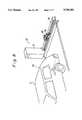
- FIG. 1is a schematic side view showing an electric vehicle parked in a garage and a charger on the ground;
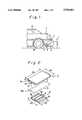
- FIG. 2is a perspective view of an inductive coupler of a preferred embodiment of the invention, comprising primary and secondary devices shown here in their decoupled state:
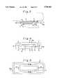
- FIG. 3is a side sectional view of the inductive coupler of FIG. 2 in the coupled state
- FIG. 4is a front view of the inductive coupler of FIG. 3:
- FIG. 5is a plan view showing relative positions of primary and secondary coils of the inductive coupler
- FIG. 6is a perspective view of a primary device of the inductive coupler, showing a modified primary coil:
- FIG. 7is a side sectional view of the inductive coupler of FIG. 6 in its coupled position:
- FIG. 8is a perspective view showing a second preferred embodiment of an inductive coupler according to the invention.
- FIG. 9is an enlarged perspective view of the inductive coupler of FIG. 8, showing its decoupled state
- FIG. 10is a perspective view of the inductive coupler of FIG. 9, showing its coupled state:
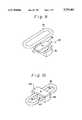
- FIG. 11is a perspective view of a modified inductive coupler of the second embodiment
- FIG. 12is a perspective view of another modified inductive coupler of the second embodiment:
- FIG. 13is a schematic side view showing a third preferred embodiment of an inductive coupler according to the invention.
- FIG. 14is an enlarged side sectional view of the inductive coupler of FIG. 13.
- FIG. 1there is shown a positional relation between an electric vehicle 2 (hereinafter “vehicle") having a battery (not shown) to be charged and parked with its rear wheels 2a in contact with a wheel stop 13 in a garage and a charger 1 located at a predetermined position on the ground in the garage.
- vehiclean electric vehicle 2
- the charger 1has an arm 3 extending horizontally toward the vehicle 2 for supporting at its free end a primary device 4 of an inductive coupler.
- the support arm 3is movable horizontally in widthwise or lateral direction of the vehicle 2 and also in a vertical direction toward and away from a secondary device 7 mounted on the rear bottom of the vehicle 2 and forming the inductive coupler with the above primary device 4. Normally, the support arm 3 is retracted at its lowered position at a stroke end of its lateral movement.
- the primary device 4includes a core 5 made of magnetic material and having an E-shape in cross section and a coil 6 wound around the center projection 5a of the E-shaped core.
- the center projection 5a of the core 5extends or elongates in the longitudinal direction of the vehicle 2.
- the core 5has projections 5b on opposite lateral sides of and in parallel to the center projection 5a.
- each of the projections 5b on opposite lateral sides of the primary core 5has a wedge-shaped jaw portion 5c extending inward so as to present an enlarged flat top surface.
- the primary core 5 in the illustrated embodimenthas a length D1 of about 100 mm and a width D2 of about 160 mm.
- the primary core 5thus constructed is fixedly mounted to the free end of the support arm 3 for the horizontal and vertical movements therewith.
- the secondary device 7 of the inductive couplerincludes a core 8 made of magnetic material and having a rectangular plate shape and a coil 9 fixed to the bottom surface of the core 8.
- the secondary core 8has a length D3 about twice as much as the length D1 of the primary core 4, or about 200 mm, and a width D4 that is the same as the width D2 of the primary core, or about 160 mm.
- the secondary coil 9is generally shaped into a rectangular shape whose longitudinal dimension along D3 is substantially greater than its lateral dimension along D4, and the opposite longitudinal ends thereof extends beyond longitudinal ends of the core 8. As shown in FIGS. 2 through 5, the rear end portion of 9a the secondary coil 9 that extends beyond the corresponding end of the core 8 is bent upward away from the primary coil 6 so that, even when the devices 4, 7 are coupled as will be described below, the secondary device 7 is movable rightward, as seen in FIG. 2, in the longitudinal direction without interference between the primary and secondary coils 6, 9. Thus, the bent portion 9a of the secondary coil 9 provides for a path as indicated by arrow 12 for that secondary coil. As shown in FIG. 3, the secondary core 8 is fixedly mounted to the vehicle bottom by way of a fixing member 10.
- the primary coil 6is placed within a substantially rectangular space defined by the secondary coil 9, as shown in FIGS. 3 through 6.
- the secondary coil 9is so sized and formed that a longitudinal spaced interval D5 is provided between the adjacent longitudinal ends of the primary and secondary coils 6, 9 in the above coupled position, the dimension of which spaced interval D5 is much greater than a lateral spaced interval D6 between the adjacent lateral sides of the two coils 6, 9.
- the ground charger 1is located at a predetermined location in the garage in relation to the wheel stop 13 against which the vehicle 2 is parked with its rear wheels 2a bearing against the stop.
- the arm 3 carrying at its end the primary device 4 of the inductive coupleris movable by any suitable means both horizontally in lateral direction of the vehicle 2 and in a vertical direction.
- the charger 1is so arranged that, when the vehicle 2 is parked properly against the wheel stop 13, its secondary device 7 is positioned such that the primary device 4 moving horizontally in the lateral direction relative to the stop 13 can move past just below the secondary device 7 as shown in FIG. 1.
- Battery charging operationis commenced after the vehicle 2 has been parked against the wheel stop 13.
- the support arm 3, which is then located at its lowered position,is moved from one stroke end of its lateral movement toward the other stroke end until the primary device 4 reaches a position immediately below the secondary device 7, which position may be detected by any suitable means such as photoelectric or magnetic sensor (not shown).
- the support arm 3is elevated to bring the primary device 4 into engagement with the secondary device 7 for coupling thereof as shown in FIGS. 3 and 4.
- the primary coil 6is accommodated within the space of secondary coil 9 and the top surfaces of the projections 5a, 5b of the primary core 5 are in abutment with the bottom surface of the secondary core 8, thus the coupler then forming a device similar to a transformer.
- the charger 1supplies to the primary coil 6 a charging AC current, which induces a similar current in the secondary coil 9 under the effect of electromagnetic induction and the AC current thus transferred from the primary to the secondary is rectified by any appropriate circuit into a DC current which is delivered to the battery for charging the same.
- the provision of the spaced interval D5 on opposite longitudinal end portionshelps the primary coil 6 to be brought safely within the rectangular space of the secondary coil 9 without interfering with the secondary coil 9 even if the vehicle 2 is parked with an error in the positioning of its secondary device 7 with respect to the primary device 4 in the longitudinal direction of the vehicle 2.
- the secondary device 7can be withdrawn and released safely from the primary device 4 without colliding therewith because of the provision of the path 12 provided by the upward bend 9a of the secondary coil 9 at its rear end portion.
- top surfaces of the two lateral projections 5b of the primary core 5are widened at 5c, a slight offset or error, if any, in the lateral positioning of the primary device 4 with respect to the secondary device 7 can be accommodated and, therefore, adequate abutment can be effected between the primary and secondary cores 5, 8, thus a magnetic circuit being formed by the cores.
- the use of the flat core 8 for the secondary device 7 on the vehicle 2, which is lighter than an E-shaped core,can contribute to reduction in weight of the vehicle 2. It is to be noted, however, that the secondary core according to the invention does not necessarily have to be flat-shaped, but it may be of an E-shape while the primary core is configured flat.
- the secondary device 7 of the inductive couplerwhich is installed on the rear bottom of the vehicle 2 in the above-described embodiment, may be mounted on the front bottom, or either front or rear side of the vehicle.
- a driver or a charger operatorcan drive to move the vehicle forward with less effort to locate the vehicle against the wheel stop 13.
- the coupled condition of the primary and secondary devicescan be checked advantageously visually.
- the secondary coil 9may be formed without the upward bending, 9a as shown in FIGS. 6 and 7.
- the path 12 in the embodiment shown in FIG. 2is not available and, therefore, the coil 9 will collide against the secondary coil 6 if the vehicle is driven away from the wheel stop 13 while the devices 4, 7 are in coupled position.
- such modified secondary coil 9is advantageous in that the coil can be manufactured with less cost.
- the primary and secondary devices 4, 7 of the inductive couplermay be arranged so as to be turned by 90°, that is, be disposed with the sides along D1 and D3 thereof oriented perpendicularly with respect to the longitudinal direction of the vehicle 2.
- the spaced intervals D5will be provided in the lateral direction of the vehicle and, therefore, an error in parking position of the vehicle in the lateral direction can be accommodated by these spaces.
- a ground charger 20disposed in a garage and including a charger unit 21, a primary device 25 of the inductive coupler, a wheel stop 22, a device 23 for moving the primary device 25 along the extension of the wheel stop 22 and a pantograph type device 24 for elevating the primary device 25.
- the vehicle 2carries on its rear bottom a secondary device comprising a coil 29. With the vehicle 2 located in the garage with its rear wheels bearing against the wheel stop 22, the secondary coil 29 is placed just above the path along which the primary device 25 is moved by the device 23.
- the primary device 25includes an E-shaped core 26, a primary coil 27 wound around the center projection of the E-shape of the core and a member 28 made of a magnetic material and rotatable about its center by a drive mechanism (not shown) so as to cover and uncover the recesses of the core 26 on opposite sides of the center projection of the E-shape.
- the secondary device consisting of the coil 29does not include a core.
- battery charging operationis initiated after the vehicle 2 has been parked properly in the garage in relation to the wheel stop 22.
- the primary device 25is shown at its elevated position in the middle of the wheel stop 22 for the sake of clarity of illustration of the device 25, it is normally retracted at its lowered position at a stroke end of its crosswise or lateral movement along the wheel stop 22.
- the primary device 25is started to move from the retracted position in the lateral direction along the wheel stop 22 toward the other stroke end until it reaches a position immediately below the secondary coil 29, which position may be detected by any suitable means such as photoelectric sensor or magnetic sensor (not shown).
- the primary device 25is raised by the elevating device 24 to a position where part of the secondary coil 29 is inserted in the recesses of the core 26 as shown in FIG. 10, whereupon the member 28 is rotated by 90° to close the core recesses as shown in FIG. 10, thus coupling of the primary device 25 and the secondary coil 29 is completed.
- the secondary coil 29is sized and shaped so as to provide relatively large spaced interval D6 between the primary coil 27 and the respective longitudinal ends of secondary coil 29 so that secondary coil 29 can be placed in the recesses of the core 26 without interference with the rotatable member 28 and also that coupling is effected safely without interference between the primary device 25 and the secondary coil 29 even if the vehicle is parked with an error in the longitudinal positioning of its secondary coil 29 with respect to the primary device 25.
- the vehicle 2can advantageously reduce its weight by the weight of a core if any were otherwise used.
- the core 26 of the primary device 25may be substituted by a core having a shape other than the E-shape shown in FIGS. 9 and 10.
- a C-shaped core 31may be used which is open in the upper portion thereof and has a primary coil 34 wound around the bottom portion thereof.
- This core 31has a slide member 33 made of magnetic material and movable along the arc of the C-shape so as to close the opening after the secondary coil 32 has been received in the core 31.
- an E-shape core 35 with a pair of swingable members 36 made of magnetic materialmay be utilized. In this modification, the members 36 are swung in the directions of the arrows so as to close the recesses of the core 35 after they receive therein the secondary coil 37.
- FIGS. 13 and 14The following will describe a third embodiment of the invention with reference to FIGS. 13 and 14. Since this embodiment differs from the first embodiment only in the manner of mounting the primary and secondary devices 4, 7 of the coupler as understood from FIG. 13, like reference numerals are used for like elements or parts and the description will focus only on features different from those of the first embodiment.
- the secondary device 7 having a coil 9 with no upward bendis substantially the same as the corresponding device shown in FIG. 6.
- no path 12 as provided in the embodiment of FIG. 2is provided.
- the secondary device 7is mounted to the vehicle's rear bottom by way of the fixing member 10 at an inclination angle ⁇ in respect of the longitudinal direction of the vehicle 2 with the rear end of the secondary device 7 raised or disposed closer to the vehicle bottom than the opposite front end thereof.
- the primary device 4is mounted on the support arm 3 at the same inclination angle ⁇ . Therefore, the primary and secondary devices of the coupler 4, 7 are couplingly engaged at the angle ⁇ as shown in FIG. 14.
- the angle ⁇is selected such that a horizontal line L1 passing at the highest point of the inclined primary coil 6 in the coupled position of the coupler is located below a horizontal line L2 passing at the lowest point of the rear end of the inclined secondary coil 9, as illustrated in FIG. 14.
- the secondary coil 9when the vehicle 2 is moved inadvertently away from the wheel stop 13 during charging or immediately after the charging is over, the secondary coil 9 can be moved clear of the primary coil 6 without collision therebetween. Since the secondary coil 9 of this embodiment needs not be bent to provide the path 12 as in the first embodiment, the secondary device 7 of the coupler can be manufactured with less cost.
- the secondary core 8 of FIG. 14does not necessarily have to be flat-shaped, but it may be of an E-shape while the primary core is configured flat.
- the location of the secondary device 7is not limited to the rear bottom of the vehicle 2, but it may be provided on the front bottom of the vehicle 2.
Landscapes
- Engineering & Computer Science (AREA)
- Power Engineering (AREA)
- Transportation (AREA)
- Mechanical Engineering (AREA)
- Computer Networks & Wireless Communication (AREA)
- Charge And Discharge Circuits For Batteries Or The Like (AREA)
Abstract
Description
The present invention relates generally to an apparatus for charging a battery of an electric vehicle, and more specifically to an inductive coupler for use in such battery charging apparatus.
A battery charging system for electric vehicles plays a key role for utilization of such vehicles and, therefore, the ease of handling the charging system helps to make the electric vehicles acceptable to the market and more popular among the prospective users. Thus, an easy to handle battery charging system is strongly demanded by the electric vehicle market.
Generally, a battery charger is located on the ground in a garage or like place, and battery charging can be accomplished by engaging or operatively connecting an inductive coupler comprising a primary device forming a part of the battery charger connected to a power source and a secondary device carried by an electric vehicle and connected to a propulsion battery of the vehicle. In a typical inductive coupler, the primary device includes a primary coil wound around a core and connected to the power source, while the secondary device includes a secondary coil wound around a core and connected to the battery on the electric vehicle, and the primary device is movable relative to the vehicle so as to be operatively engaged or coupled with the secondary device carried by the vehicle. In this coupled position of the inductive coupler, the primary and secondary devices are disposed one on the other with the two cores in abutment with each other and the primary coil accommodated within an open space defined by the secondary coil. As is well known in the art, flowing a charging current in the primary coil induces an electromotive force in the secondary coil through electromagnetic induction and the resulting electromotive force in the secondary is utilized for charging the battery.
Though the primary and secondary devices may be coupled manually by a vehicle driver according to a method as disclosed in U.S. Pat. No. 5,216,402, the coupling operation should be performed advantageously in an automatic manner for the sake of ease and convenience. Such automatic coupling may be accomplished by driving a vehicle to a predetermined parking location in a garage and then moving the primary device of the coupler, using any suitable drive means such as an actuator, to a position where it is coupled with the secondary device.
In order to achieve the desired coupling for successful charging in the above automatic coupling arrangement, however, the vehicle should be driven carefully and parked at an intended position relative to the ground charger. For this purpose, a wheel stop is placed at an appropriate location in the garage to help the driver to stop the vehicle at the intended position.
Even with the aid of such wheel stop, it may happen depending on the driving skill that the driver moves the vehicle only to a position short from the wheel stop or beyond the intended position with the wheels partly placed on the stop. Thus, it is still difficult for the vehicle to be stopped at an optimum position for battery charging operation.
It can be readily understood that, if the vehicle is parked with a slight error in the longitudinal direction of the vehicle with respect to its intended charging position, the movable primary coil may strike the secondary coil without being snugly fitted within the space of the latter coil. If this happens, battery charging operation cannot be initiated. Alternatively, even if charging can be initiated somehow, the charger will fail to transfer enough power to charge the battery to a desired level.
Another problem is that if the vehicle is driven inadvertently to move away from the primary device during the charging operation or just after the battery charging operation is completed but before the couple is decoupled, the secondary coil then moving horizontally away from the primary coil will collide against the primary coil, thereby inviting a fear of damage to either or both of the coils. Additionally, the secondary device having a core increases the weight of the vehicle.
Therefore, an object of the present invention is to provide an inductive coupler which is designed so as to prevent interference between the primary and secondary coils when the coupler is being engaged for coupling.
Another object of the invention is to provide an inductive coupler in which an error in the relative positioning of the secondary device of the coupler with respect to the primary device does not seriously affect the battery charging efficiency.
Still another object of the invention is to provide an inductive coupler which can prevent collision between the primary and secondary coils even if the vehicle is moved inadvertently in a direction to decouple the coupler during charging operation.
The inductive coupler according to the invention, which is designed to solve the above problems, is adapted for use in a battery charging system for an electric vehicle parked at a position, for example, in a garage, which inductive coupler comprises a primary device connected to an AC power source and having a primary coil, and a secondary device mounted on the vehicle and having a secondary coil. The primary and secondary devices are coupleable with one (i.e., either) of the primary and secondary coils placed within an open space defined by the other of the two coils for inducing an electromotive force in the secondary coil by flowing a current in the primary coil in the coupled position of the coupler. Said other coil surrounding said one coil is formed and sized so as to have a greater dimension than said one coil as measured in a given direction with respect to the parked vehicle so that a spaced interval formed between the two coils in the above given direction is greater than that in a direction perpendicular to the given direction.
By so forming the above other coil in relation to the one coil, the resulting greater spaced interval between the two coils in the specific direction of the vehicle can accommodate an error, if any occurs, in the relative positions between the primary and secondary devices of the inductive coupler in the above direction.
In order to prevent the collision between the primary and secondary coils even when the vehicle is moved inadvertently in a direction to decouple the coupler, the above other coil is provided with a portion that is bent so as to provide a path through which the one coil moves without colliding against the other coil due to relative movement of the two coils. According to the invention, the collision due to inadvertently driving the vehicle is prevented also by disposing the primary and secondary devices at a specific orientation with respect to the longitudinal direction of the vehicle and at a selected inclination angle.
In one form of embodiment according to the invention, the secondary device includes a core having at least one recess for receiving therein part of the primary coil such that a spaced interval between the primary and secondary coils in a given direction is greater than that in a direction perpendicular to the given direction, and one core that surrounds the other core has a portion movable to close the recess after said primary and secondary devices are coupled together.
The above and other objects and features of the invention will be apparent from the following detailed description of preferred embodiments of the invention in conjunction with the accompanying drawings.
FIG. 1 is a schematic side view showing an electric vehicle parked in a garage and a charger on the ground;
FIG. 2 is a perspective view of an inductive coupler of a preferred embodiment of the invention, comprising primary and secondary devices shown here in their decoupled state:
FIG. 3 is a side sectional view of the inductive coupler of FIG. 2 in the coupled state;
FIG. 4 is a front view of the inductive coupler of FIG. 3:
FIG. 5 is a plan view showing relative positions of primary and secondary coils of the inductive coupler;
FIG. 6 is a perspective view of a primary device of the inductive coupler, showing a modified primary coil:
FIG. 7 is a side sectional view of the inductive coupler of FIG. 6 in its coupled position:
FIG. 8 is a perspective view showing a second preferred embodiment of an inductive coupler according to the invention;
FIG. 9 is an enlarged perspective view of the inductive coupler of FIG. 8, showing its decoupled state;
FIG. 10 is a perspective view of the inductive coupler of FIG. 9, showing its coupled state:
FIG. 11 is a perspective view of a modified inductive coupler of the second embodiment;
FIG. 12 is a perspective view of another modified inductive coupler of the second embodiment:
FIG. 13 is a schematic side view showing a third preferred embodiment of an inductive coupler according to the invention;
FIG. 14 is an enlarged side sectional view of the inductive coupler of FIG. 13.
FIRST EMBODIMENT
The first preferred embodiment of inductive coupler according to the present invention will be described while having reference to FIGS. 1 to 5. Referring to FIG. 1, there is shown a positional relation between an electric vehicle 2 (hereinafter "vehicle") having a battery (not shown) to be charged and parked with itsrear wheels 2a in contact with awheel stop 13 in a garage and a charger 1 located at a predetermined position on the ground in the garage. The charger 1 has anarm 3 extending horizontally toward thevehicle 2 for supporting at its free end aprimary device 4 of an inductive coupler. Thesupport arm 3 is movable horizontally in widthwise or lateral direction of thevehicle 2 and also in a vertical direction toward and away from a secondary device 7 mounted on the rear bottom of thevehicle 2 and forming the inductive coupler with the aboveprimary device 4. Normally, thesupport arm 3 is retracted at its lowered position at a stroke end of its lateral movement.
As shown in FIG. 2, theprimary device 4 includes acore 5 made of magnetic material and having an E-shape in cross section and acoil 6 wound around thecenter projection 5a of the E-shaped core. Thecenter projection 5a of thecore 5 extends or elongates in the longitudinal direction of thevehicle 2. Thecore 5 hasprojections 5b on opposite lateral sides of and in parallel to thecenter projection 5a. As shown more clearly in FIG. 4, each of theprojections 5b on opposite lateral sides of theprimary core 5 has a wedge-shaped jaw portion 5c extending inward so as to present an enlarged flat top surface. Incidentally, theprimary core 5 in the illustrated embodiment has a length D1 of about 100 mm and a width D2 of about 160 mm. Theprimary core 5 thus constructed is fixedly mounted to the free end of thesupport arm 3 for the horizontal and vertical movements therewith.
Referring back to FIG. 2, the secondary device 7 of the inductive coupler includes acore 8 made of magnetic material and having a rectangular plate shape and acoil 9 fixed to the bottom surface of thecore 8. Thesecondary core 8 has a length D3 about twice as much as the length D1 of theprimary core 4, or about 200 mm, and a width D4 that is the same as the width D2 of the primary core, or about 160 mm.
Thesecondary coil 9 is generally shaped into a rectangular shape whose longitudinal dimension along D3 is substantially greater than its lateral dimension along D4, and the opposite longitudinal ends thereof extends beyond longitudinal ends of thecore 8. As shown in FIGS. 2 through 5, the rear end portion of 9a thesecondary coil 9 that extends beyond the corresponding end of thecore 8 is bent upward away from theprimary coil 6 so that, even when thedevices 4, 7 are coupled as will be described below, the secondary device 7 is movable rightward, as seen in FIG. 2, in the longitudinal direction without interference between the primary andsecondary coils bent portion 9a of thesecondary coil 9 provides for a path as indicated byarrow 12 for that secondary coil. As shown in FIG. 3, thesecondary core 8 is fixedly mounted to the vehicle bottom by way of a fixingmember 10.
In the coupled position of the coupler, theprimary coil 6 is placed within a substantially rectangular space defined by thesecondary coil 9, as shown in FIGS. 3 through 6. Referring specifically to FIG. 5, thesecondary coil 9 is so sized and formed that a longitudinal spaced interval D5 is provided between the adjacent longitudinal ends of the primary andsecondary coils coils
The ground charger 1 is located at a predetermined location in the garage in relation to thewheel stop 13 against which thevehicle 2 is parked with itsrear wheels 2a bearing against the stop. As mentioned earlier, thearm 3 carrying at its end theprimary device 4 of the inductive coupler is movable by any suitable means both horizontally in lateral direction of thevehicle 2 and in a vertical direction. In the illustrated embodiment, the charger 1 is so arranged that, when thevehicle 2 is parked properly against thewheel stop 13, its secondary device 7 is positioned such that theprimary device 4 moving horizontally in the lateral direction relative to thestop 13 can move past just below the secondary device 7 as shown in FIG. 1.
The following will describe the operation of the inductive coupler thus constructed.
Battery charging operation is commenced after thevehicle 2 has been parked against thewheel stop 13. Thesupport arm 3, which is then located at its lowered position, is moved from one stroke end of its lateral movement toward the other stroke end until theprimary device 4 reaches a position immediately below the secondary device 7, which position may be detected by any suitable means such as photoelectric or magnetic sensor (not shown). Subsequently, thesupport arm 3 is elevated to bring theprimary device 4 into engagement with the secondary device 7 for coupling thereof as shown in FIGS. 3 and 4. In the coupled state, theprimary coil 6 is accommodated within the space ofsecondary coil 9 and the top surfaces of theprojections primary core 5 are in abutment with the bottom surface of thesecondary core 8, thus the coupler then forming a device similar to a transformer. In this coupled condition, the charger 1 supplies to the primary coil 6 a charging AC current, which induces a similar current in thesecondary coil 9 under the effect of electromagnetic induction and the AC current thus transferred from the primary to the secondary is rectified by any appropriate circuit into a DC current which is delivered to the battery for charging the same.
In raising theprimary device 4 for coupling engagement with the secondary device 7, the provision of the spaced interval D5 on opposite longitudinal end portions helps theprimary coil 6 to be brought safely within the rectangular space of thesecondary coil 9 without interfering with thesecondary coil 9 even if thevehicle 2 is parked with an error in the positioning of its secondary device 7 with respect to theprimary device 4 in the longitudinal direction of thevehicle 2.
Additionally, even if thevehicle 2 is moved inadvertently forward away from thestop 13 during or just after the charging operation while thedevices 4, 7 are still in their coupled position, the secondary device 7 can be withdrawn and released safely from theprimary device 4 without colliding therewith because of the provision of thepath 12 provided by theupward bend 9a of thesecondary coil 9 at its rear end portion.
Because the top surfaces of the twolateral projections 5b of theprimary core 5 are widened at 5c, a slight offset or error, if any, in the lateral positioning of theprimary device 4 with respect to the secondary device 7 can be accommodated and, therefore, adequate abutment can be effected between the primary andsecondary cores
Additionally, the use of theflat core 8 for the secondary device 7 on thevehicle 2, which is lighter than an E-shaped core, can contribute to reduction in weight of thevehicle 2. It is to be noted, however, that the secondary core according to the invention does not necessarily have to be flat-shaped, but it may be of an E-shape while the primary core is configured flat.
The secondary device 7 of the inductive coupler, which is installed on the rear bottom of thevehicle 2 in the above-described embodiment, may be mounted on the front bottom, or either front or rear side of the vehicle. In the case of the front bottom mounting, a driver or a charger operator can drive to move the vehicle forward with less effort to locate the vehicle against thewheel stop 13. In the case of the front or rear side mounting, the coupled condition of the primary and secondary devices can be checked advantageously visually.
According to the invention, thesecondary coil 9 may be formed without the upward bending, 9a as shown in FIGS. 6 and 7. In this case, thepath 12 in the embodiment shown in FIG. 2 is not available and, therefore, thecoil 9 will collide against thesecondary coil 6 if the vehicle is driven away from thewheel stop 13 while thedevices 4, 7 are in coupled position. However, such modifiedsecondary coil 9 is advantageous in that the coil can be manufactured with less cost.
As a further modification of the above embodiment, the primary andsecondary devices 4, 7 of the inductive coupler may be arranged so as to be turned by 90°, that is, be disposed with the sides along D1 and D3 thereof oriented perpendicularly with respect to the longitudinal direction of thevehicle 2. In such a modified embodiment, the spaced intervals D5 will be provided in the lateral direction of the vehicle and, therefore, an error in parking position of the vehicle in the lateral direction can be accommodated by these spaces.
SECOND EMBODIMENT
The following will describe a second preferred embodiment of the present invention while having reference to FIGS. 8 to 10.
There is shown aground charger 20 disposed in a garage and including acharger unit 21, aprimary device 25 of the inductive coupler, awheel stop 22, adevice 23 for moving theprimary device 25 along the extension of thewheel stop 22 and a pantograph type device 24 for elevating theprimary device 25. On the other hand, thevehicle 2 carries on its rear bottom a secondary device comprising acoil 29. With thevehicle 2 located in the garage with its rear wheels bearing against thewheel stop 22, thesecondary coil 29 is placed just above the path along which theprimary device 25 is moved by thedevice 23.
As seen more clearly in FIG. 9, theprimary device 25 includes anE-shaped core 26, aprimary coil 27 wound around the center projection of the E-shape of the core and amember 28 made of a magnetic material and rotatable about its center by a drive mechanism (not shown) so as to cover and uncover the recesses of the core 26 on opposite sides of the center projection of the E-shape. As apparent from FIGS. 9 and 10, the secondary device consisting of thecoil 29 does not include a core.
In this embodiment, battery charging operation is initiated after thevehicle 2 has been parked properly in the garage in relation to thewheel stop 22. Though theprimary device 25 is shown at its elevated position in the middle of thewheel stop 22 for the sake of clarity of illustration of thedevice 25, it is normally retracted at its lowered position at a stroke end of its crosswise or lateral movement along thewheel stop 22. When the vehicle is parked against thewheel stop 22, theprimary device 25 is started to move from the retracted position in the lateral direction along thewheel stop 22 toward the other stroke end until it reaches a position immediately below thesecondary coil 29, which position may be detected by any suitable means such as photoelectric sensor or magnetic sensor (not shown). Subsequently, theprimary device 25 is raised by the elevating device 24 to a position where part of thesecondary coil 29 is inserted in the recesses of the core 26 as shown in FIG. 10, whereupon themember 28 is rotated by 90° to close the core recesses as shown in FIG. 10, thus coupling of theprimary device 25 and thesecondary coil 29 is completed.
As seen clearly in FIG. 10, thesecondary coil 29 is sized and shaped so as to provide relatively large spaced interval D6 between theprimary coil 27 and the respective longitudinal ends ofsecondary coil 29 so thatsecondary coil 29 can be placed in the recesses of thecore 26 without interference with therotatable member 28 and also that coupling is effected safely without interference between theprimary device 25 and thesecondary coil 29 even if the vehicle is parked with an error in the longitudinal positioning of itssecondary coil 29 with respect to theprimary device 25. In this embodiment, wherein the secondary device of the coupler dispenses with a heavy core, thevehicle 2 can advantageously reduce its weight by the weight of a core if any were otherwise used.
As a modification of this second embodiment, thecore 26 of theprimary device 25 may be substituted by a core having a shape other than the E-shape shown in FIGS. 9 and 10. As exemplified in FIG. 11, a C-shapedcore 31 may be used which is open in the upper portion thereof and has aprimary coil 34 wound around the bottom portion thereof. Thiscore 31 has aslide member 33 made of magnetic material and movable along the arc of the C-shape so as to close the opening after thesecondary coil 32 has been received in thecore 31. As a still further modification, anE-shape core 35 with a pair ofswingable members 36 made of magnetic material may be utilized. In this modification, themembers 36 are swung in the directions of the arrows so as to close the recesses of the core 35 after they receive therein thesecondary coil 37.
THIRD EMBODIMENT
The following will describe a third embodiment of the invention with reference to FIGS. 13 and 14. Since this embodiment differs from the first embodiment only in the manner of mounting the primary andsecondary devices 4, 7 of the coupler as understood from FIG. 13, like reference numerals are used for like elements or parts and the description will focus only on features different from those of the first embodiment.
As shown in FIG. 14, the secondary device 7 having acoil 9 with no upward bend is substantially the same as the corresponding device shown in FIG. 6. Thus, nopath 12 as provided in the embodiment of FIG. 2 is provided. The secondary device 7 is mounted to the vehicle's rear bottom by way of the fixingmember 10 at an inclination angle θ in respect of the longitudinal direction of thevehicle 2 with the rear end of the secondary device 7 raised or disposed closer to the vehicle bottom than the opposite front end thereof. Likewise, theprimary device 4 is mounted on thesupport arm 3 at the same inclination angle θ. Therefore, the primary and secondary devices of thecoupler 4, 7 are couplingly engaged at the angle θ as shown in FIG. 14.
The angle θ is selected such that a horizontal line L1 passing at the highest point of the inclinedprimary coil 6 in the coupled position of the coupler is located below a horizontal line L2 passing at the lowest point of the rear end of the inclinedsecondary coil 9, as illustrated in FIG. 14.
In this embodiment of the coupler, when thevehicle 2 is moved inadvertently away from thewheel stop 13 during charging or immediately after the charging is over, thesecondary coil 9 can be moved clear of theprimary coil 6 without collision therebetween. Since thesecondary coil 9 of this embodiment needs not be bent to provide thepath 12 as in the first embodiment, the secondary device 7 of the coupler can be manufactured with less cost.
As in the aforementioned modification from the first embodiment, thesecondary core 8 of FIG. 14 does not necessarily have to be flat-shaped, but it may be of an E-shape while the primary core is configured flat.
According to the invention, the location of the secondary device 7 is not limited to the rear bottom of thevehicle 2, but it may be provided on the front bottom of thevehicle 2.
While the invention has been described with reference to the specific embodiments, it is to be understood that the present invention can be practiced with further changes and modifications without departing from the spirit or scope thereof.
Claims (10)
1. An inductive coupler in a battery charging system for an electric vehicle comprising a primary device having a primary coil for connection to a power source, and a secondary device for mounting on said vehicle and having a secondary coil for coupling to a battery in said vehicle, said primary and secondary devices being assembleable with one of said primary and secondary coils being insertable within an open space defined by the other of said primary and secondary coils for coupling said coils electromagnetically to induce an electromotive force in said secondary coil upon establishing a current in said primary coil in the assembled condition of the coupler, said other of said primary and secondary coils being formed and sized larger than said one of said primary and secondary coils at least along a predetermined axis to provide a first clearance at least in the direction of said predetermined axis between said coils when assembled, said first clearance in the direction of said predetermined axis being greater than any clearance in the direction orthogonal to said predetermined axis, and means for mounting said primary device adjacent a space for parking said vehicle with means for moving said primary device at least horizontally into a selectable position for engaging and assuming said assembled condition with said secondary device.
2. An inductive coupler according to claim 1, wherein said other of said primary and secondary coils has a portion bent so as to provide a path through which said one of said primary and secondary coils is movable without colliding against said other of said primary and secondary coils to permit relative movement of said secondary coil away from said primary coil upon movement of said vehicle away from said primary device while said primary device is in said selectable position.
3. An inductive coupler according to claim 2, wherein said secondary device is provided with means for mounting on the rear bottom of the vehicle, said primary and secondary devices are assembleable with said primary coil placed within an open space defined by said secondary coil, and said path provided by said bent portion of said other of said coils is formed in the portion of said secondary coil that when mounted on a vehicle located in said space for parking said vehicle extends towards said primary device.
4. An inductive coupler according to claim 1, wherein said predetermined axis corresponds to the longitudinal direction of said space for parking said vehicle.
5. An inductive coupler according to claim 1, wherein said predetermined axis is related orthogonally to the longitudinal direction of said space for parking said vehicle.
6. An inductive coupler according to claim 1, wherein said primary and secondary devices are arranged at such an inclined disposition with respect to the longitudinal direction of said space for parking said vehicle that each of said coils can move relative to the other coil without colliding against the other when a vehicle is moved away from said primary device while said coupler is in the assembled position.
7. An inductive coupler in a battery charging system for an electric vehicle comprising a primary device having a primary coil and a core for connection to a power source, and a secondary device for mounting on said vehicle and having a secondary coil for coupling to a battery in said vehicle, said primary and secondary devices being assembleable with one of said primary and secondary coils being insertable within an open space defined by the other of said primary and secondary coils for coupling said coils electromagnetically to induce an electromotive force in said secondary coil upon establishing a current in said primary coil in the assembled condition of the coupler, said other of said primary and secondary coils being formed and sized larger than said one of said primary and secondary coils at least along a predetermined axis to provide a first clearance at least in the direction of said predetermined axis between said coils when assembled, said first clearance in the direction of said predetermined axis being greater than any clearance in the direction orthogonal to said predetermined axis, said core having a portion which is movable to form a closed magnetic circuit after said primary and secondary devices are assembled together, and means for mounting said primary device adjacent a space for parking said vehicle with means for moving said primary device at least horizontally into a selectable position for engaging and assuming said assembled condition with said secondary device.
8. An inductive coupler according to claim 7, wherein said core has an E-shape having first and second recesses respectively on opposite sides of a center leg of the E-shape for receiving therein part of said secondary coil.
9. An inductive coupler according to claim 8, wherein said movable portion of said core is rotatable so as to close said recesses after said primary and secondary devices are assembled together.
10. An inductive coupler according to claim 7, wherein said core has a C-shape having a recess therein for receiving therein part of said secondary coil.
Applications Claiming Priority (4)
| Application Number | Priority Date | Filing Date | Title |
|---|---|---|---|
| JP7162521AJPH0917665A (en) | 1995-06-28 | 1995-06-28 | Charger coupler |
| JP7162523AJPH0917667A (en) | 1995-06-28 | 1995-06-28 | Charger coupler |
| JP7-162523 | 1995-06-28 | ||
| JP7-162521 | 1995-06-28 |
Publications (1)
| Publication Number | Publication Date |
|---|---|
| US5703461Atrue US5703461A (en) | 1997-12-30 |
Family
ID=26488286
Family Applications (1)
| Application Number | Title | Priority Date | Filing Date |
|---|---|---|---|
| US08/671,218Expired - Fee RelatedUS5703461A (en) | 1995-06-28 | 1996-06-27 | Inductive coupler for electric vehicle charger |
Country Status (1)
| Country | Link |
|---|---|
| US (1) | US5703461A (en) |
Cited By (143)
| Publication number | Priority date | Publication date | Assignee | Title |
|---|---|---|---|---|
| WO1998031073A3 (en)* | 1997-01-13 | 1998-11-12 | Advanced Metal Technologies Lt | Electrical coupler device |
| US5909100A (en)* | 1996-08-09 | 1999-06-01 | Sumitomo Wiring Systems, Ltd. | Charging connector for electric vehicle |
| US6157162A (en)* | 1998-09-09 | 2000-12-05 | Honda Giken Kogyo Kabushiki Kaisha | Battery charging apparatus for electric vehicles |
| WO2001037926A1 (en)* | 1999-11-22 | 2001-05-31 | Abiomed, Inc. | Apparatus for transferring energy across a boundary |
| US6525510B1 (en)* | 2001-08-08 | 2003-02-25 | Hitachi, Ltd. | Vehicle operating system |
| US6619342B2 (en) | 2001-05-11 | 2003-09-16 | General Hydrogen Corporation | Wheel stop service port |
| US6691749B2 (en) | 2002-01-10 | 2004-02-17 | General Hydrogen Corporation | Service coupling |
| US6722903B2 (en) | 2002-01-10 | 2004-04-20 | General Hydrogen Corporation | Service plug configuration |
| US20050083020A1 (en)* | 2003-10-20 | 2005-04-21 | Baarman David W. | Electrostatic charge storage assembly |
| EP1596461A1 (en)* | 2004-05-11 | 2005-11-16 | Concens A/S | Combination of a power supply and an electrical appliance with a magnetic holder |
| CN1297463C (en)* | 2001-05-30 | 2007-01-31 | 株式会社日立制作所 | Movable body system |
| US20080300660A1 (en)* | 2007-06-01 | 2008-12-04 | Michael Sasha John | Power generation for implantable devices |
| US20090011616A1 (en)* | 2007-07-04 | 2009-01-08 | Satyajit Patwardhan | Widely deployable charging system for vehicles |
| US20090189458A1 (en)* | 2008-01-23 | 2009-07-30 | Toyota Jidosha Kabushiki Kaisha | Vehicle power supply apparatus and vehicle window member |
| US20100007307A1 (en)* | 2008-07-09 | 2010-01-14 | Access Business Group International Llc | Wireless charging system |
| US20100141042A1 (en)* | 2008-09-27 | 2010-06-10 | Kesler Morris P | Wireless energy transfer systems |
| US20100161217A1 (en)* | 2008-12-22 | 2010-06-24 | Aisin Aw Co., Ltd. | Devices, methods, and programs that provide vehicle guidance for power reception |
| US20100201309A1 (en)* | 2009-02-10 | 2010-08-12 | Meek Ivan C | Systems and methods for coupling a vehicle to an external grid and/or network |
| US20100270970A1 (en)* | 2009-04-28 | 2010-10-28 | Shoichi Toya | Device housing a battery and charging pad |
| US20100277121A1 (en)* | 2008-09-27 | 2010-11-04 | Hall Katherine L | Wireless energy transfer between a source and a vehicle |
| US20110018361A1 (en)* | 2005-07-12 | 2011-01-27 | Aristeidis Karalis | Tuning and gain control in electro-magnetic power systems |
| WO2010063385A3 (en)* | 2008-12-02 | 2011-04-07 | Voith Patent Gmbh | Underwater power plant having removable nacelle |
| US20110121778A1 (en)* | 2007-10-25 | 2011-05-26 | Toyota Jidosha Kabushiki Kaisha | Electrical powered vehicle and power feeding device for vehicle |
| US20110181240A1 (en)* | 2010-01-05 | 2011-07-28 | Access Business Group International Llc | Inductive charging system for electric vehicle |
| US20110221387A1 (en)* | 2010-03-09 | 2011-09-15 | Robert Louis Steigerwald | System and method for charging an energy storage system for an electric or hybrid-electric vehicle |
| US8035341B2 (en) | 2010-07-12 | 2011-10-11 | Better Place GmbH | Staged deployment for electrical charge spots |
| WO2011131158A1 (en)* | 2010-04-23 | 2011-10-27 | Helmut Jakob | Device for automatically parking motor vehicles |
| DE102010025951A1 (en) | 2010-07-02 | 2012-01-05 | Paul Vahle Gmbh & Co. Kg | Charging station for system for inductively charging vehicle battery, has primary coil arrangement oscillating and/or hanging on device, building or garage and mounted and freely oscillating around axles |
| US8118147B2 (en) | 2009-09-11 | 2012-02-21 | Better Place GmbH | Cable dispensing system |
| WO2011114208A3 (en)* | 2010-03-16 | 2012-02-23 | Toyota Jidosha Kabushiki Kaisha | Inductively charged vehicle with automatic positioning |
| US8164300B2 (en)* | 2008-09-19 | 2012-04-24 | Better Place GmbH | Battery exchange station |
| US8246376B2 (en) | 2009-09-14 | 2012-08-21 | Better Place GmbH | Electrical connector with flexible blade shaped handle |
| EP2524834A1 (en) | 2011-05-18 | 2012-11-21 | Brusa Elektronik AG | Device for inductive charging of at least one electrical energy storage device of an electric car |
| US20120293109A1 (en)* | 2011-05-19 | 2012-11-22 | Yariv Glazer | Method and System for Efficiently Exploiting Renewable Electrical Energy Sources |
| US8384344B1 (en) | 2010-08-17 | 2013-02-26 | David D. Rogers | System and method for charging a battery within a vehicle |
| US8441154B2 (en) | 2008-09-27 | 2013-05-14 | Witricity Corporation | Multi-resonator wireless energy transfer for exterior lighting |
| EP2330262A3 (en)* | 2009-12-04 | 2013-05-29 | WAP Wöhr Automatikparksysteme GmbH & Co KG | Method for operating a parking facility and parking facility |
| US8454377B2 (en) | 2008-09-19 | 2013-06-04 | Better Place GmbH | System for electrically connecting batteries to electric vehicles |
| WO2013083625A1 (en) | 2011-12-09 | 2013-06-13 | Bayerische Motoren Werke Aktiengesellschaft | Motor vehicle |
| US8466583B2 (en) | 2008-09-27 | 2013-06-18 | Witricity Corporation | Tunable wireless energy transfer for outdoor lighting applications |
| US8497601B2 (en) | 2008-09-27 | 2013-07-30 | Witricity Corporation | Wireless energy transfer converters |
| US8509981B2 (en) | 2011-05-25 | 2013-08-13 | Toyota Motor Engineering & Manufacturing North America, Inc. | Docking stations for automated guided vehicles |
| US8587153B2 (en) | 2008-09-27 | 2013-11-19 | Witricity Corporation | Wireless energy transfer using high Q resonators for lighting applications |
| US8618696B2 (en) | 2008-09-27 | 2013-12-31 | Witricity Corporation | Wireless energy transfer systems |
| US8629578B2 (en) | 2008-09-27 | 2014-01-14 | Witricity Corporation | Wireless energy transfer systems |
| US8643326B2 (en) | 2008-09-27 | 2014-02-04 | Witricity Corporation | Tunable wireless energy transfer systems |
| US8667452B2 (en) | 2011-11-04 | 2014-03-04 | Witricity Corporation | Wireless energy transfer modeling tool |
| US8669676B2 (en) | 2008-09-27 | 2014-03-11 | Witricity Corporation | Wireless energy transfer across variable distances using field shaping with magnetic materials to improve the coupling factor |
| US20140084231A1 (en)* | 2011-06-09 | 2014-03-27 | Suntory Holdings Limited | Safety fence |
| US8692412B2 (en) | 2008-09-27 | 2014-04-08 | Witricity Corporation | Temperature compensation in a wireless transfer system |
| US8716903B2 (en) | 2008-09-27 | 2014-05-06 | Witricity Corporation | Low AC resistance conductor designs |
| US8723366B2 (en) | 2008-09-27 | 2014-05-13 | Witricity Corporation | Wireless energy transfer resonator enclosures |
| US8725330B2 (en) | 2010-06-02 | 2014-05-13 | Bryan Marc Failing | Increasing vehicle security |
| US8729737B2 (en) | 2008-09-27 | 2014-05-20 | Witricity Corporation | Wireless energy transfer using repeater resonators |
| US8760007B2 (en) | 2005-07-12 | 2014-06-24 | Massachusetts Institute Of Technology | Wireless energy transfer with high-Q to more than one device |
| US8772973B2 (en) | 2008-09-27 | 2014-07-08 | Witricity Corporation | Integrated resonator-shield structures |
| CN103946045A (en)* | 2011-11-22 | 2014-07-23 | 丰田自动车株式会社 | Vehicle and power transmission system |
| US20140240076A1 (en)* | 2011-10-18 | 2014-08-28 | Audi Ag | Secondary transformer unit for placing on a vehicle with an electric drive and vehicle with an electric drive |
| US8847548B2 (en) | 2008-09-27 | 2014-09-30 | Witricity Corporation | Wireless energy transfer for implantable devices |
| US8901779B2 (en) | 2008-09-27 | 2014-12-02 | Witricity Corporation | Wireless energy transfer with resonator arrays for medical applications |
| US8901778B2 (en) | 2008-09-27 | 2014-12-02 | Witricity Corporation | Wireless energy transfer with variable size resonators for implanted medical devices |
| US8907531B2 (en) | 2008-09-27 | 2014-12-09 | Witricity Corporation | Wireless energy transfer with variable size resonators for medical applications |
| US8912687B2 (en) | 2008-09-27 | 2014-12-16 | Witricity Corporation | Secure wireless energy transfer for vehicle applications |
| US8917056B2 (en) | 2011-05-04 | 2014-12-23 | Samsung Sdi Co., Ltd. | Charging apparatus for electric vehicle |
| US8922066B2 (en) | 2008-09-27 | 2014-12-30 | Witricity Corporation | Wireless energy transfer with multi resonator arrays for vehicle applications |
| US8928276B2 (en) | 2008-09-27 | 2015-01-06 | Witricity Corporation | Integrated repeaters for cell phone applications |
| US8933594B2 (en) | 2008-09-27 | 2015-01-13 | Witricity Corporation | Wireless energy transfer for vehicles |
| US8937408B2 (en) | 2008-09-27 | 2015-01-20 | Witricity Corporation | Wireless energy transfer for medical applications |
| US8947186B2 (en) | 2008-09-27 | 2015-02-03 | Witricity Corporation | Wireless energy transfer resonator thermal management |
| US8946938B2 (en) | 2008-09-27 | 2015-02-03 | Witricity Corporation | Safety systems for wireless energy transfer in vehicle applications |
| US8957549B2 (en) | 2008-09-27 | 2015-02-17 | Witricity Corporation | Tunable wireless energy transfer for in-vehicle applications |
| US8963488B2 (en) | 2008-09-27 | 2015-02-24 | Witricity Corporation | Position insensitive wireless charging |
| US9035499B2 (en) | 2008-09-27 | 2015-05-19 | Witricity Corporation | Wireless energy transfer for photovoltaic panels |
| CN104641532A (en)* | 2012-09-27 | 2015-05-20 | 株式会社Ihi | Power-feeding device for vehicle |
| US9065423B2 (en) | 2008-09-27 | 2015-06-23 | Witricity Corporation | Wireless energy distribution system |
| US9093853B2 (en) | 2008-09-27 | 2015-07-28 | Witricity Corporation | Flexible resonator attachment |
| US9106203B2 (en) | 2008-09-27 | 2015-08-11 | Witricity Corporation | Secure wireless energy transfer in medical applications |
| US9105959B2 (en) | 2008-09-27 | 2015-08-11 | Witricity Corporation | Resonator enclosure |
| US9160203B2 (en) | 2008-09-27 | 2015-10-13 | Witricity Corporation | Wireless powered television |
| US9184595B2 (en) | 2008-09-27 | 2015-11-10 | Witricity Corporation | Wireless energy transfer in lossy environments |
| CN105052012A (en)* | 2013-03-26 | 2015-11-11 | 松下知识产权经营株式会社 | Power supplying device, power receiving device, and power supplying system |
| US9197093B2 (en) | 2010-12-24 | 2015-11-24 | Toyota Jidosha Kabushiki Kaisha | Non-contact charging system, non-contact charging method, non-contact charging type vehicle, and non-contact charging management apparatus |
| US20160009187A1 (en)* | 2013-05-14 | 2016-01-14 | Ihi Corporation | Wireless power transmission device and vehicle |
| US9246336B2 (en) | 2008-09-27 | 2016-01-26 | Witricity Corporation | Resonator optimizations for wireless energy transfer |
| US20160052415A1 (en)* | 2014-08-25 | 2016-02-25 | Ford Global Technologies, Llc | Self-Locating Multi-Coil System for Wireless Vehicle Charging |
| US9287607B2 (en) | 2012-07-31 | 2016-03-15 | Witricity Corporation | Resonator fine tuning |
| US20160087449A1 (en)* | 2013-03-29 | 2016-03-24 | Nissan Motor Co., Ltd. | Power supply device and power transmission unit for power supply device |
| US9306635B2 (en) | 2012-01-26 | 2016-04-05 | Witricity Corporation | Wireless energy transfer with reduced fields |
| US9318922B2 (en) | 2008-09-27 | 2016-04-19 | Witricity Corporation | Mechanically removable wireless power vehicle seat assembly |
| US9318257B2 (en) | 2011-10-18 | 2016-04-19 | Witricity Corporation | Wireless energy transfer for packaging |
| US9343922B2 (en) | 2012-06-27 | 2016-05-17 | Witricity Corporation | Wireless energy transfer for rechargeable batteries |
| US9365104B2 (en) | 2010-04-21 | 2016-06-14 | Toyota Jidosha Kabushiki Kaisha | Parking assist device for vehicle and electrically powered vehicle including the same |
| US9369182B2 (en) | 2008-09-27 | 2016-06-14 | Witricity Corporation | Wireless energy transfer using variable size resonators and system monitoring |
| US9384885B2 (en) | 2011-08-04 | 2016-07-05 | Witricity Corporation | Tunable wireless power architectures |
| US9396867B2 (en) | 2008-09-27 | 2016-07-19 | Witricity Corporation | Integrated resonator-shield structures |
| US9404954B2 (en) | 2012-10-19 | 2016-08-02 | Witricity Corporation | Foreign object detection in wireless energy transfer systems |
| US9425638B2 (en) | 1999-11-01 | 2016-08-23 | Anthony Sabo | Alignment independent and self-aligning inductive power transfer system |
| US9421388B2 (en) | 2007-06-01 | 2016-08-23 | Witricity Corporation | Power generation for implantable devices |
| US9442172B2 (en) | 2011-09-09 | 2016-09-13 | Witricity Corporation | Foreign object detection in wireless energy transfer systems |
| US9449757B2 (en) | 2012-11-16 | 2016-09-20 | Witricity Corporation | Systems and methods for wireless power system with improved performance and/or ease of use |
| US9515494B2 (en) | 2008-09-27 | 2016-12-06 | Witricity Corporation | Wireless power system including impedance matching network |
| US9536655B2 (en) | 2010-12-01 | 2017-01-03 | Toyota Jidosha Kabushiki Kaisha | Wireless power feeding apparatus, vehicle, and method of controlling wireless power feeding system |
| US9544683B2 (en) | 2008-09-27 | 2017-01-10 | Witricity Corporation | Wirelessly powered audio devices |
| US9577449B2 (en) | 2014-01-17 | 2017-02-21 | Honda Motor Co., Ltd. | Method and apparatus to align wireless charging coils |
| US9595378B2 (en) | 2012-09-19 | 2017-03-14 | Witricity Corporation | Resonator enclosure |
| US9601266B2 (en) | 2008-09-27 | 2017-03-21 | Witricity Corporation | Multiple connected resonators with a single electronic circuit |
| US9601270B2 (en) | 2008-09-27 | 2017-03-21 | Witricity Corporation | Low AC resistance conductor designs |
| US9602168B2 (en) | 2010-08-31 | 2017-03-21 | Witricity Corporation | Communication in wireless energy transfer systems |
| US20170101015A1 (en)* | 2014-03-25 | 2017-04-13 | Winslim | Inductive charging device for an electric vehicle |
| US9744858B2 (en) | 2008-09-27 | 2017-08-29 | Witricity Corporation | System for wireless energy distribution in a vehicle |
| US9754718B2 (en) | 2008-09-27 | 2017-09-05 | Witricity Corporation | Resonator arrays for wireless energy transfer |
| US9780573B2 (en) | 2014-02-03 | 2017-10-03 | Witricity Corporation | Wirelessly charged battery system |
| US9831682B2 (en) | 2008-10-01 | 2017-11-28 | Massachusetts Institute Of Technology | Efficient near-field wireless energy transfer using adiabatic system variations |
| US9837860B2 (en) | 2014-05-05 | 2017-12-05 | Witricity Corporation | Wireless power transmission systems for elevators |
| US9842688B2 (en) | 2014-07-08 | 2017-12-12 | Witricity Corporation | Resonator balancing in wireless power transfer systems |
| US9842687B2 (en) | 2014-04-17 | 2017-12-12 | Witricity Corporation | Wireless power transfer systems with shaped magnetic components |
| US9843217B2 (en) | 2015-01-05 | 2017-12-12 | Witricity Corporation | Wireless energy transfer for wearables |
| US9857821B2 (en) | 2013-08-14 | 2018-01-02 | Witricity Corporation | Wireless power transfer frequency adjustment |
| US9892849B2 (en) | 2014-04-17 | 2018-02-13 | Witricity Corporation | Wireless power transfer systems with shield openings |
| US9902271B2 (en) | 2008-11-07 | 2018-02-27 | Toyota Jidosha Kabushiki Kaisha | Power feeding system for vehicle, electrically powered vehicle and power feeding apparatus for vehicle |
| US9929721B2 (en) | 2015-10-14 | 2018-03-27 | Witricity Corporation | Phase and amplitude detection in wireless energy transfer systems |
| US9948145B2 (en) | 2011-07-08 | 2018-04-17 | Witricity Corporation | Wireless power transfer for a seat-vest-helmet system |
| US9952266B2 (en) | 2014-02-14 | 2018-04-24 | Witricity Corporation | Object detection for wireless energy transfer systems |
| US9954375B2 (en) | 2014-06-20 | 2018-04-24 | Witricity Corporation | Wireless power transfer systems for surfaces |
| US10018744B2 (en) | 2014-05-07 | 2018-07-10 | Witricity Corporation | Foreign object detection in wireless energy transfer systems |
| US10063110B2 (en) | 2015-10-19 | 2018-08-28 | Witricity Corporation | Foreign object detection in wireless energy transfer systems |
| US10063104B2 (en) | 2016-02-08 | 2018-08-28 | Witricity Corporation | PWM capacitor control |
| US10075019B2 (en) | 2015-11-20 | 2018-09-11 | Witricity Corporation | Voltage source isolation in wireless power transfer systems |
| US10131236B2 (en) | 2015-04-17 | 2018-11-20 | Lear Corporation | Wireless charging magnetic structure |
| US10141788B2 (en) | 2015-10-22 | 2018-11-27 | Witricity Corporation | Dynamic tuning in wireless energy transfer systems |
| US10248899B2 (en) | 2015-10-06 | 2019-04-02 | Witricity Corporation | RFID tag and transponder detection in wireless energy transfer systems |
| US10263473B2 (en) | 2016-02-02 | 2019-04-16 | Witricity Corporation | Controlling wireless power transfer systems |
| US10399449B2 (en)* | 2016-08-08 | 2019-09-03 | Hyundai Motor Company | Wireless charging control apparatus and method for optimal charging by adjusting the inclination of the electric vehicle being charged |
| US10424976B2 (en) | 2011-09-12 | 2019-09-24 | Witricity Corporation | Reconfigurable control architectures and algorithms for electric vehicle wireless energy transfer systems |
| US10574091B2 (en) | 2014-07-08 | 2020-02-25 | Witricity Corporation | Enclosures for high power wireless power transfer systems |
| EP3614527A1 (en)* | 2018-08-24 | 2020-02-26 | Siemens Aktiengesellschaft | System and method for wireless charging of electric vehicles |
| US20200122591A1 (en)* | 2017-06-28 | 2020-04-23 | Salih Music | Wireless transmission system of electricity for electric vehicles |
| US20210086601A1 (en)* | 2019-09-23 | 2021-03-25 | Abb Schweiz Ag | Linear positioning system for automatic charging device |
| US11031818B2 (en) | 2017-06-29 | 2021-06-08 | Witricity Corporation | Protection and control of wireless power systems |
| DE102020119127A1 (en) | 2020-07-21 | 2022-01-27 | Audi Aktiengesellschaft | Method for operating a motor vehicle and corresponding motor vehicle |
| US11296557B2 (en) | 2017-05-30 | 2022-04-05 | Wireless Advanced Vehicle Electrification, Llc | Single feed multi-pad wireless charging |
| US11462943B2 (en) | 2018-01-30 | 2022-10-04 | Wireless Advanced Vehicle Electrification, Llc | DC link charging of capacitor in a wireless power transfer pad |
| US20230256846A1 (en)* | 2020-07-09 | 2023-08-17 | Korea Institute Of Machinery & Materials | Vehicle charging robot device |
Citations (5)
| Publication number | Priority date | Publication date | Assignee | Title |
|---|---|---|---|---|
| US4347472A (en)* | 1980-10-20 | 1982-08-31 | Lemelson Jerome H | Apparatus and method for charging a battery in a vehicle |
| US4800328A (en)* | 1986-07-18 | 1989-01-24 | Inductran Inc. | Inductive power coupling with constant voltage output |
| US5070293A (en)* | 1989-03-02 | 1991-12-03 | Nippon Soken, Inc. | Electric power transmitting device with inductive coupling |
| US5216402A (en)* | 1992-01-22 | 1993-06-01 | Hughes Aircraft Company | Separable inductive coupler |
| US5539296A (en)* | 1992-12-15 | 1996-07-23 | Kabushiki Kaisha Toyoda Jidoshokki Seisakusho | Method and system of charging a propulsion battery of an electrically powered vehicle |
- 1996
- 1996-06-27USUS08/671,218patent/US5703461A/ennot_activeExpired - Fee Related
Patent Citations (5)
| Publication number | Priority date | Publication date | Assignee | Title |
|---|---|---|---|---|
| US4347472A (en)* | 1980-10-20 | 1982-08-31 | Lemelson Jerome H | Apparatus and method for charging a battery in a vehicle |
| US4800328A (en)* | 1986-07-18 | 1989-01-24 | Inductran Inc. | Inductive power coupling with constant voltage output |
| US5070293A (en)* | 1989-03-02 | 1991-12-03 | Nippon Soken, Inc. | Electric power transmitting device with inductive coupling |
| US5216402A (en)* | 1992-01-22 | 1993-06-01 | Hughes Aircraft Company | Separable inductive coupler |
| US5539296A (en)* | 1992-12-15 | 1996-07-23 | Kabushiki Kaisha Toyoda Jidoshokki Seisakusho | Method and system of charging a propulsion battery of an electrically powered vehicle |
Cited By (273)
| Publication number | Priority date | Publication date | Assignee | Title |
|---|---|---|---|---|
| US5909100A (en)* | 1996-08-09 | 1999-06-01 | Sumitomo Wiring Systems, Ltd. | Charging connector for electric vehicle |
| WO1998031073A3 (en)* | 1997-01-13 | 1998-11-12 | Advanced Metal Technologies Lt | Electrical coupler device |
| US6157162A (en)* | 1998-09-09 | 2000-12-05 | Honda Giken Kogyo Kabushiki Kaisha | Battery charging apparatus for electric vehicles |
| US9425638B2 (en) | 1999-11-01 | 2016-08-23 | Anthony Sabo | Alignment independent and self-aligning inductive power transfer system |
| WO2001037926A1 (en)* | 1999-11-22 | 2001-05-31 | Abiomed, Inc. | Apparatus for transferring energy across a boundary |
| US6619342B2 (en) | 2001-05-11 | 2003-09-16 | General Hydrogen Corporation | Wheel stop service port |
| CN1297463C (en)* | 2001-05-30 | 2007-01-31 | 株式会社日立制作所 | Movable body system |
| US6525510B1 (en)* | 2001-08-08 | 2003-02-25 | Hitachi, Ltd. | Vehicle operating system |
| US6691749B2 (en) | 2002-01-10 | 2004-02-17 | General Hydrogen Corporation | Service coupling |
| US6722903B2 (en) | 2002-01-10 | 2004-04-20 | General Hydrogen Corporation | Service plug configuration |
| US20050083020A1 (en)* | 2003-10-20 | 2005-04-21 | Baarman David W. | Electrostatic charge storage assembly |
| EP1596461A1 (en)* | 2004-05-11 | 2005-11-16 | Concens A/S | Combination of a power supply and an electrical appliance with a magnetic holder |
| WO2005109563A1 (en)* | 2004-05-11 | 2005-11-17 | Concens A/S | Combination of a power supply and an electrical appliance with a magnetic holder |
| US10666091B2 (en) | 2005-07-12 | 2020-05-26 | Massachusetts Institute Of Technology | Wireless non-radiative energy transfer |
| US9444265B2 (en) | 2005-07-12 | 2016-09-13 | Massachusetts Institute Of Technology | Wireless energy transfer |
| US10141790B2 (en) | 2005-07-12 | 2018-11-27 | Massachusetts Institute Of Technology | Wireless non-radiative energy transfer |
| US10097044B2 (en) | 2005-07-12 | 2018-10-09 | Massachusetts Institute Of Technology | Wireless energy transfer |
| US9831722B2 (en) | 2005-07-12 | 2017-11-28 | Massachusetts Institute Of Technology | Wireless non-radiative energy transfer |
| US9509147B2 (en) | 2005-07-12 | 2016-11-29 | Massachusetts Institute Of Technology | Wireless energy transfer |
| US9450421B2 (en) | 2005-07-12 | 2016-09-20 | Massachusetts Institute Of Technology | Wireless non-radiative energy transfer |
| US9450422B2 (en) | 2005-07-12 | 2016-09-20 | Massachusetts Institute Of Technology | Wireless energy transfer |
| US20110018361A1 (en)* | 2005-07-12 | 2011-01-27 | Aristeidis Karalis | Tuning and gain control in electro-magnetic power systems |
| US8760007B2 (en) | 2005-07-12 | 2014-06-24 | Massachusetts Institute Of Technology | Wireless energy transfer with high-Q to more than one device |
| US11685270B2 (en) | 2005-07-12 | 2023-06-27 | Mit | Wireless energy transfer |
| US11685271B2 (en) | 2005-07-12 | 2023-06-27 | Massachusetts Institute Of Technology | Wireless non-radiative energy transfer |
| US9065286B2 (en) | 2005-07-12 | 2015-06-23 | Massachusetts Institute Of Technology | Wireless non-radiative energy transfer |
| US8791599B2 (en) | 2005-07-12 | 2014-07-29 | Massachusetts Institute Of Technology | Wireless energy transfer to a moving device between high-Q resonators |
| US8772971B2 (en) | 2005-07-12 | 2014-07-08 | Massachusetts Institute Of Technology | Wireless energy transfer across variable distances with high-Q capacitively-loaded conducting-wire loops |
| US8772972B2 (en) | 2005-07-12 | 2014-07-08 | Massachusetts Institute Of Technology | Wireless energy transfer across a distance to a moving device |
| US8766485B2 (en) | 2005-07-12 | 2014-07-01 | Massachusetts Institute Of Technology | Wireless energy transfer over distances to a moving device |
| US8760008B2 (en) | 2005-07-12 | 2014-06-24 | Massachusetts Institute Of Technology | Wireless energy transfer over variable distances between resonators of substantially similar resonant frequencies |
| US9421388B2 (en) | 2007-06-01 | 2016-08-23 | Witricity Corporation | Power generation for implantable devices |
| US9095729B2 (en) | 2007-06-01 | 2015-08-04 | Witricity Corporation | Wireless power harvesting and transmission with heterogeneous signals |
| US8805530B2 (en) | 2007-06-01 | 2014-08-12 | Witricity Corporation | Power generation for implantable devices |
| US20080300660A1 (en)* | 2007-06-01 | 2008-12-04 | Michael Sasha John | Power generation for implantable devices |
| US9101777B2 (en) | 2007-06-01 | 2015-08-11 | Witricity Corporation | Wireless power harvesting and transmission with heterogeneous signals |
| US9318898B2 (en) | 2007-06-01 | 2016-04-19 | Witricity Corporation | Wireless power harvesting and transmission with heterogeneous signals |
| US9843230B2 (en) | 2007-06-01 | 2017-12-12 | Witricity Corporation | Wireless power harvesting and transmission with heterogeneous signals |
| US10420951B2 (en) | 2007-06-01 | 2019-09-24 | Witricity Corporation | Power generation for implantable devices |
| US10348136B2 (en) | 2007-06-01 | 2019-07-09 | Witricity Corporation | Wireless power harvesting and transmission with heterogeneous signals |
| US9943697B2 (en) | 2007-06-01 | 2018-04-17 | Witricity Corporation | Power generation for implantable devices |
| US8307967B2 (en) | 2007-07-04 | 2012-11-13 | Satyajit Patwardhan | Widely deployable charging system for vehicles |
| US20090011616A1 (en)* | 2007-07-04 | 2009-01-08 | Satyajit Patwardhan | Widely deployable charging system for vehicles |
| US20110121778A1 (en)* | 2007-10-25 | 2011-05-26 | Toyota Jidosha Kabushiki Kaisha | Electrical powered vehicle and power feeding device for vehicle |
| US9421868B2 (en) | 2007-10-25 | 2016-08-23 | Toyota Jidosha Kabushiki Kaisha | Electrical powered vehicle and power feeding device for vehicle |
| US9180779B2 (en) | 2007-10-25 | 2015-11-10 | Toyota Jidosha Kabushiki Kaisha | Electrical powered vehicle and power feeding device for vehicle |
| US9024575B2 (en)* | 2007-10-25 | 2015-05-05 | Toyota Jidosha Kabushiki Kaisha | Electrical powered vehicle and power feeding device for vehicle |
| US20120032525A1 (en)* | 2007-10-25 | 2012-02-09 | Toyota Jidosha Kabushiki Kaisha | Electrical Powered Vehicle and Power Feeding Device for Vehicle |
| US20090189458A1 (en)* | 2008-01-23 | 2009-07-30 | Toyota Jidosha Kabushiki Kaisha | Vehicle power supply apparatus and vehicle window member |
| US8115342B2 (en)* | 2008-01-23 | 2012-02-14 | Toyota Jidosha Kabushiki Kaisha | Vehicle power supply apparatus and vehicle window member |
| US8531153B2 (en) | 2008-07-09 | 2013-09-10 | Access Business Group International Llc | Wireless charging system |
| US20100007307A1 (en)* | 2008-07-09 | 2010-01-14 | Access Business Group International Llc | Wireless charging system |
| US9143003B2 (en) | 2008-07-09 | 2015-09-22 | Access Business Group International Llc | Wireless charging system |
| US8638062B2 (en) | 2008-07-09 | 2014-01-28 | Access Business Group International Llc | Wireless charging system |
| US8454377B2 (en) | 2008-09-19 | 2013-06-04 | Better Place GmbH | System for electrically connecting batteries to electric vehicles |
| US8517132B2 (en) | 2008-09-19 | 2013-08-27 | Better Place GmbH | Electric vehicle battery system |
| US8164300B2 (en)* | 2008-09-19 | 2012-04-24 | Better Place GmbH | Battery exchange station |
| US9744858B2 (en) | 2008-09-27 | 2017-08-29 | Witricity Corporation | System for wireless energy distribution in a vehicle |
| US10673282B2 (en) | 2008-09-27 | 2020-06-02 | Witricity Corporation | Tunable wireless energy transfer systems |
| US8643326B2 (en) | 2008-09-27 | 2014-02-04 | Witricity Corporation | Tunable wireless energy transfer systems |
| US12263743B2 (en) | 2008-09-27 | 2025-04-01 | Witricity Corporation | Wireless power system modules |
| US8669676B2 (en) | 2008-09-27 | 2014-03-11 | Witricity Corporation | Wireless energy transfer across variable distances using field shaping with magnetic materials to improve the coupling factor |
| US10084348B2 (en) | 2008-09-27 | 2018-09-25 | Witricity Corporation | Wireless energy transfer for implantable devices |
| US8692412B2 (en) | 2008-09-27 | 2014-04-08 | Witricity Corporation | Temperature compensation in a wireless transfer system |
| US8716903B2 (en) | 2008-09-27 | 2014-05-06 | Witricity Corporation | Low AC resistance conductor designs |
| US8723366B2 (en) | 2008-09-27 | 2014-05-13 | Witricity Corporation | Wireless energy transfer resonator enclosures |
| US20100141042A1 (en)* | 2008-09-27 | 2010-06-10 | Kesler Morris P | Wireless energy transfer systems |
| US8729737B2 (en) | 2008-09-27 | 2014-05-20 | Witricity Corporation | Wireless energy transfer using repeater resonators |
| US10097011B2 (en) | 2008-09-27 | 2018-10-09 | Witricity Corporation | Wireless energy transfer for photovoltaic panels |
| US8618696B2 (en) | 2008-09-27 | 2013-12-31 | Witricity Corporation | Wireless energy transfer systems |
| US8587153B2 (en) | 2008-09-27 | 2013-11-19 | Witricity Corporation | Wireless energy transfer using high Q resonators for lighting applications |
| US9843228B2 (en) | 2008-09-27 | 2017-12-12 | Witricity Corporation | Impedance matching in wireless power systems |
| US8772973B2 (en) | 2008-09-27 | 2014-07-08 | Witricity Corporation | Integrated resonator-shield structures |
| US10218224B2 (en) | 2008-09-27 | 2019-02-26 | Witricity Corporation | Tunable wireless energy transfer systems |
| US11958370B2 (en) | 2008-09-27 | 2024-04-16 | Witricity Corporation | Wireless power system modules |
| US10230243B2 (en) | 2008-09-27 | 2019-03-12 | Witricity Corporation | Flexible resonator attachment |
| US10264352B2 (en) | 2008-09-27 | 2019-04-16 | Witricity Corporation | Wirelessly powered audio devices |
| US9806541B2 (en) | 2008-09-27 | 2017-10-31 | Witricity Corporation | Flexible resonator attachment |
| US9780605B2 (en) | 2008-09-27 | 2017-10-03 | Witricity Corporation | Wireless power system with associated impedance matching network |
| US8847548B2 (en) | 2008-09-27 | 2014-09-30 | Witricity Corporation | Wireless energy transfer for implantable devices |
| US10300800B2 (en) | 2008-09-27 | 2019-05-28 | Witricity Corporation | Shielding in vehicle wireless power systems |
| US9754718B2 (en) | 2008-09-27 | 2017-09-05 | Witricity Corporation | Resonator arrays for wireless energy transfer |
| US8901779B2 (en) | 2008-09-27 | 2014-12-02 | Witricity Corporation | Wireless energy transfer with resonator arrays for medical applications |
| US8901778B2 (en) | 2008-09-27 | 2014-12-02 | Witricity Corporation | Wireless energy transfer with variable size resonators for implanted medical devices |
| US8907531B2 (en) | 2008-09-27 | 2014-12-09 | Witricity Corporation | Wireless energy transfer with variable size resonators for medical applications |
| US8912687B2 (en) | 2008-09-27 | 2014-12-16 | Witricity Corporation | Secure wireless energy transfer for vehicle applications |
| US9748039B2 (en) | 2008-09-27 | 2017-08-29 | Witricity Corporation | Wireless energy transfer resonator thermal management |
| US8922066B2 (en) | 2008-09-27 | 2014-12-30 | Witricity Corporation | Wireless energy transfer with multi resonator arrays for vehicle applications |
| US8928276B2 (en) | 2008-09-27 | 2015-01-06 | Witricity Corporation | Integrated repeaters for cell phone applications |
| US8933594B2 (en) | 2008-09-27 | 2015-01-13 | Witricity Corporation | Wireless energy transfer for vehicles |
| US8937408B2 (en) | 2008-09-27 | 2015-01-20 | Witricity Corporation | Wireless energy transfer for medical applications |
| US9544683B2 (en) | 2008-09-27 | 2017-01-10 | Witricity Corporation | Wirelessly powered audio devices |
| US8947186B2 (en) | 2008-09-27 | 2015-02-03 | Witricity Corporation | Wireless energy transfer resonator thermal management |
| US8946938B2 (en) | 2008-09-27 | 2015-02-03 | Witricity Corporation | Safety systems for wireless energy transfer in vehicle applications |
| US8957549B2 (en) | 2008-09-27 | 2015-02-17 | Witricity Corporation | Tunable wireless energy transfer for in-vehicle applications |
| US8963488B2 (en) | 2008-09-27 | 2015-02-24 | Witricity Corporation | Position insensitive wireless charging |
| US8497601B2 (en) | 2008-09-27 | 2013-07-30 | Witricity Corporation | Wireless energy transfer converters |
| US9035499B2 (en) | 2008-09-27 | 2015-05-19 | Witricity Corporation | Wireless energy transfer for photovoltaic panels |
| US9742204B2 (en) | 2008-09-27 | 2017-08-22 | Witricity Corporation | Wireless energy transfer in lossy environments |
| US9065423B2 (en) | 2008-09-27 | 2015-06-23 | Witricity Corporation | Wireless energy distribution system |
| US9711991B2 (en) | 2008-09-27 | 2017-07-18 | Witricity Corporation | Wireless energy transfer converters |
| US10340745B2 (en) | 2008-09-27 | 2019-07-02 | Witricity Corporation | Wireless power sources and devices |
| US9093853B2 (en) | 2008-09-27 | 2015-07-28 | Witricity Corporation | Flexible resonator attachment |
| US9246336B2 (en) | 2008-09-27 | 2016-01-26 | Witricity Corporation | Resonator optimizations for wireless energy transfer |
| US9106203B2 (en) | 2008-09-27 | 2015-08-11 | Witricity Corporation | Secure wireless energy transfer in medical applications |
| US8466583B2 (en) | 2008-09-27 | 2013-06-18 | Witricity Corporation | Tunable wireless energy transfer for outdoor lighting applications |
| US9105959B2 (en) | 2008-09-27 | 2015-08-11 | Witricity Corporation | Resonator enclosure |
| US8629578B2 (en) | 2008-09-27 | 2014-01-14 | Witricity Corporation | Wireless energy transfer systems |
| US10410789B2 (en) | 2008-09-27 | 2019-09-10 | Witricity Corporation | Integrated resonator-shield structures |
| US9601270B2 (en) | 2008-09-27 | 2017-03-21 | Witricity Corporation | Low AC resistance conductor designs |
| US9160203B2 (en) | 2008-09-27 | 2015-10-13 | Witricity Corporation | Wireless powered television |
| US9184595B2 (en) | 2008-09-27 | 2015-11-10 | Witricity Corporation | Wireless energy transfer in lossy environments |
| US11479132B2 (en) | 2008-09-27 | 2022-10-25 | Witricity Corporation | Wireless power transmission system enabling bidirectional energy flow |
| US9601266B2 (en) | 2008-09-27 | 2017-03-21 | Witricity Corporation | Multiple connected resonators with a single electronic circuit |
| US9596005B2 (en) | 2008-09-27 | 2017-03-14 | Witricity Corporation | Wireless energy transfer using variable size resonators and systems monitoring |
| US9584189B2 (en) | 2008-09-27 | 2017-02-28 | Witricity Corporation | Wireless energy transfer using variable size resonators and system monitoring |
| US9577436B2 (en) | 2008-09-27 | 2017-02-21 | Witricity Corporation | Wireless energy transfer for implantable devices |
| US11114896B2 (en) | 2008-09-27 | 2021-09-07 | Witricity Corporation | Wireless power system modules |
| US9662161B2 (en) | 2008-09-27 | 2017-05-30 | Witricity Corporation | Wireless energy transfer for medical applications |
| US11114897B2 (en) | 2008-09-27 | 2021-09-07 | Witricity Corporation | Wireless power transmission system enabling bidirectional energy flow |
| US8441154B2 (en) | 2008-09-27 | 2013-05-14 | Witricity Corporation | Multi-resonator wireless energy transfer for exterior lighting |
| US9515494B2 (en) | 2008-09-27 | 2016-12-06 | Witricity Corporation | Wireless power system including impedance matching network |
| US9515495B2 (en) | 2008-09-27 | 2016-12-06 | Witricity Corporation | Wireless energy transfer in lossy environments |
| US9496719B2 (en) | 2008-09-27 | 2016-11-15 | Witricity Corporation | Wireless energy transfer for implantable devices |
| US10446317B2 (en) | 2008-09-27 | 2019-10-15 | Witricity Corporation | Object and motion detection in wireless power transfer systems |
| US9318922B2 (en) | 2008-09-27 | 2016-04-19 | Witricity Corporation | Mechanically removable wireless power vehicle seat assembly |
| US10536034B2 (en) | 2008-09-27 | 2020-01-14 | Witricity Corporation | Wireless energy transfer resonator thermal management |
| US20100277121A1 (en)* | 2008-09-27 | 2010-11-04 | Hall Katherine L | Wireless energy transfer between a source and a vehicle |
| US9698607B2 (en) | 2008-09-27 | 2017-07-04 | Witricity Corporation | Secure wireless energy transfer |
| US10559980B2 (en) | 2008-09-27 | 2020-02-11 | Witricity Corporation | Signaling in wireless power systems |
| US9369182B2 (en) | 2008-09-27 | 2016-06-14 | Witricity Corporation | Wireless energy transfer using variable size resonators and system monitoring |
| US9444520B2 (en) | 2008-09-27 | 2016-09-13 | Witricity Corporation | Wireless energy transfer converters |
| US9396867B2 (en) | 2008-09-27 | 2016-07-19 | Witricity Corporation | Integrated resonator-shield structures |
| US8461719B2 (en) | 2008-09-27 | 2013-06-11 | Witricity Corporation | Wireless energy transfer systems |
| US9831682B2 (en) | 2008-10-01 | 2017-11-28 | Massachusetts Institute Of Technology | Efficient near-field wireless energy transfer using adiabatic system variations |
| US9902271B2 (en) | 2008-11-07 | 2018-02-27 | Toyota Jidosha Kabushiki Kaisha | Power feeding system for vehicle, electrically powered vehicle and power feeding apparatus for vehicle |
| US10618411B2 (en) | 2008-11-07 | 2020-04-14 | Toyota Jidosha Kabushiki Kaisha | Power feeding system for vehicle, electrically powered vehicle and power feeding apparatus for vehicle |
| US8872374B2 (en) | 2008-12-02 | 2014-10-28 | Voith Patent Gmbh | Underwater power plant having removable nacelle |
| WO2010063385A3 (en)* | 2008-12-02 | 2011-04-07 | Voith Patent Gmbh | Underwater power plant having removable nacelle |
| US20100161217A1 (en)* | 2008-12-22 | 2010-06-24 | Aisin Aw Co., Ltd. | Devices, methods, and programs that provide vehicle guidance for power reception |
| US8489315B2 (en)* | 2008-12-22 | 2013-07-16 | Aisin Aw Co., Ltd. | Devices, methods, and programs that provide vehicle guidance for power reception |
| US20100201309A1 (en)* | 2009-02-10 | 2010-08-12 | Meek Ivan C | Systems and methods for coupling a vehicle to an external grid and/or network |
| US20100270970A1 (en)* | 2009-04-28 | 2010-10-28 | Shoichi Toya | Device housing a battery and charging pad |
| US8248028B2 (en)* | 2009-04-28 | 2012-08-21 | Sanyo Electric Co., Ltd. | Device housing a battery and charging pad |
| US8118147B2 (en) | 2009-09-11 | 2012-02-21 | Better Place GmbH | Cable dispensing system |
| US8246376B2 (en) | 2009-09-14 | 2012-08-21 | Better Place GmbH | Electrical connector with flexible blade shaped handle |
| EP2330262A3 (en)* | 2009-12-04 | 2013-05-29 | WAP Wöhr Automatikparksysteme GmbH & Co KG | Method for operating a parking facility and parking facility |
| US20110181240A1 (en)* | 2010-01-05 | 2011-07-28 | Access Business Group International Llc | Inductive charging system for electric vehicle |
| US8937454B2 (en) | 2010-01-05 | 2015-01-20 | Access Business Group International Llc | Inductive charging system for electric vehicle |
| US9701212B2 (en) | 2010-01-05 | 2017-07-11 | Access Business Group International Llc | Inductive charging system for electric vehicle |
| US20110221387A1 (en)* | 2010-03-09 | 2011-09-15 | Robert Louis Steigerwald | System and method for charging an energy storage system for an electric or hybrid-electric vehicle |
| US9073442B2 (en) | 2010-03-16 | 2015-07-07 | Toyota Jidosha Kabushiki Kaisha | Inductively charged vehicle with automatic positioning |
| CN102803005B (en)* | 2010-03-16 | 2015-09-09 | 丰田自动车株式会社 | Inductively charged vehicles with automatic positioning |
| CN102803005A (en)* | 2010-03-16 | 2012-11-28 | 丰田自动车株式会社 | Inductively charged vehicles with automatic positioning |
| CN105186611A (en)* | 2010-03-16 | 2015-12-23 | 丰田自动车株式会社 | Inductive charging vehicle having automatic positioning |
| WO2011114208A3 (en)* | 2010-03-16 | 2012-02-23 | Toyota Jidosha Kabushiki Kaisha | Inductively charged vehicle with automatic positioning |
| CN105186611B (en)* | 2010-03-16 | 2017-10-24 | 丰田自动车株式会社 | With the induction charging vehicle being automatically positioned |
| US9981566B2 (en) | 2010-03-16 | 2018-05-29 | Toyota Jidosha Kabushiki Kaisha | Inductively charged vehicle with automatic positioning |
| US9365104B2 (en) | 2010-04-21 | 2016-06-14 | Toyota Jidosha Kabushiki Kaisha | Parking assist device for vehicle and electrically powered vehicle including the same |
| US20130096994A1 (en)* | 2010-04-23 | 2013-04-18 | Helmut Jakob | Device for automatically parking motor vehicles |
| WO2011131158A1 (en)* | 2010-04-23 | 2011-10-27 | Helmut Jakob | Device for automatically parking motor vehicles |
| US11186192B1 (en) | 2010-06-02 | 2021-11-30 | Bryan Marc Failing | Improving energy transfer with vehicles |
| US10124691B1 (en) | 2010-06-02 | 2018-11-13 | Bryan Marc Failing | Energy transfer with vehicles |
| US8725330B2 (en) | 2010-06-02 | 2014-05-13 | Bryan Marc Failing | Increasing vehicle security |
| US9114719B1 (en) | 2010-06-02 | 2015-08-25 | Bryan Marc Failing | Increasing vehicle security |
| US9393878B1 (en) | 2010-06-02 | 2016-07-19 | Bryan Marc Failing | Energy transfer with vehicles |
| US8841881B2 (en) | 2010-06-02 | 2014-09-23 | Bryan Marc Failing | Energy transfer with vehicles |
| DE102010025951A1 (en) | 2010-07-02 | 2012-01-05 | Paul Vahle Gmbh & Co. Kg | Charging station for system for inductively charging vehicle battery, has primary coil arrangement oscillating and/or hanging on device, building or garage and mounted and freely oscillating around axles |
| US8035341B2 (en) | 2010-07-12 | 2011-10-11 | Better Place GmbH | Staged deployment for electrical charge spots |
| US8384344B1 (en) | 2010-08-17 | 2013-02-26 | David D. Rogers | System and method for charging a battery within a vehicle |
| US9602168B2 (en) | 2010-08-31 | 2017-03-21 | Witricity Corporation | Communication in wireless energy transfer systems |
| US9536655B2 (en) | 2010-12-01 | 2017-01-03 | Toyota Jidosha Kabushiki Kaisha | Wireless power feeding apparatus, vehicle, and method of controlling wireless power feeding system |
| USRE48659E1 (en) | 2010-12-24 | 2021-07-27 | Toyota Jidosha Kabushiki Kaisha | Non-contact charging system, non-contact charging method, non-contact charging type vehicle, and non-contact charging management apparatus |
| US9197093B2 (en) | 2010-12-24 | 2015-11-24 | Toyota Jidosha Kabushiki Kaisha | Non-contact charging system, non-contact charging method, non-contact charging type vehicle, and non-contact charging management apparatus |
| US8917056B2 (en) | 2011-05-04 | 2014-12-23 | Samsung Sdi Co., Ltd. | Charging apparatus for electric vehicle |
| US9296304B2 (en) | 2011-05-18 | 2016-03-29 | Brusa Elektronik Ag | Device for inductively charging at least one electric energy store of an electric vehicle |
| WO2012156846A2 (en) | 2011-05-18 | 2012-11-22 | Brusa Elektronik Ag | Device for inductively charging at least one electric energy store of an electric vehicle |
| EP2524834A1 (en) | 2011-05-18 | 2012-11-21 | Brusa Elektronik AG | Device for inductive charging of at least one electrical energy storage device of an electric car |
| US20120293109A1 (en)* | 2011-05-19 | 2012-11-22 | Yariv Glazer | Method and System for Efficiently Exploiting Renewable Electrical Energy Sources |
| US8509981B2 (en) | 2011-05-25 | 2013-08-13 | Toyota Motor Engineering & Manufacturing North America, Inc. | Docking stations for automated guided vehicles |
| US9200416B2 (en)* | 2011-06-09 | 2015-12-01 | Suntory Holdings Limited | Safety fence |
| US20140084231A1 (en)* | 2011-06-09 | 2014-03-27 | Suntory Holdings Limited | Safety fence |
| US9948145B2 (en) | 2011-07-08 | 2018-04-17 | Witricity Corporation | Wireless power transfer for a seat-vest-helmet system |
| US9384885B2 (en) | 2011-08-04 | 2016-07-05 | Witricity Corporation | Tunable wireless power architectures |
| US10734842B2 (en) | 2011-08-04 | 2020-08-04 | Witricity Corporation | Tunable wireless power architectures |
| US9787141B2 (en) | 2011-08-04 | 2017-10-10 | Witricity Corporation | Tunable wireless power architectures |
| US11621585B2 (en) | 2011-08-04 | 2023-04-04 | Witricity Corporation | Tunable wireless power architectures |
| US10778047B2 (en) | 2011-09-09 | 2020-09-15 | Witricity Corporation | Foreign object detection in wireless energy transfer systems |
| US9442172B2 (en) | 2011-09-09 | 2016-09-13 | Witricity Corporation | Foreign object detection in wireless energy transfer systems |
| US10027184B2 (en) | 2011-09-09 | 2018-07-17 | Witricity Corporation | Foreign object detection in wireless energy transfer systems |
| US11097618B2 (en) | 2011-09-12 | 2021-08-24 | Witricity Corporation | Reconfigurable control architectures and algorithms for electric vehicle wireless energy transfer systems |
| US10424976B2 (en) | 2011-09-12 | 2019-09-24 | Witricity Corporation | Reconfigurable control architectures and algorithms for electric vehicle wireless energy transfer systems |
| US20140240076A1 (en)* | 2011-10-18 | 2014-08-28 | Audi Ag | Secondary transformer unit for placing on a vehicle with an electric drive and vehicle with an electric drive |
| US9318257B2 (en) | 2011-10-18 | 2016-04-19 | Witricity Corporation | Wireless energy transfer for packaging |
| US8875086B2 (en) | 2011-11-04 | 2014-10-28 | Witricity Corporation | Wireless energy transfer modeling tool |
| US8667452B2 (en) | 2011-11-04 | 2014-03-04 | Witricity Corporation | Wireless energy transfer modeling tool |
| CN103946045A (en)* | 2011-11-22 | 2014-07-23 | 丰田自动车株式会社 | Vehicle and power transmission system |
| CN103946045B (en)* | 2011-11-22 | 2016-08-24 | 丰田自动车株式会社 | Vehicle and electrical power transmission system |
| DE102011088112A1 (en) | 2011-12-09 | 2013-06-13 | Bayerische Motoren Werke Aktiengesellschaft | motor vehicle |
| US9662992B2 (en) | 2011-12-09 | 2017-05-30 | Bayerische Motoren Werke Aktiengesellschaft | Motor vehicle having an inductive charging coil arranged on a lubricant reservoir of an internal combustion engine of the vehicle |
| WO2013083625A1 (en) | 2011-12-09 | 2013-06-13 | Bayerische Motoren Werke Aktiengesellschaft | Motor vehicle |
| US9306635B2 (en) | 2012-01-26 | 2016-04-05 | Witricity Corporation | Wireless energy transfer with reduced fields |
| US9343922B2 (en) | 2012-06-27 | 2016-05-17 | Witricity Corporation | Wireless energy transfer for rechargeable batteries |
| US10158251B2 (en) | 2012-06-27 | 2018-12-18 | Witricity Corporation | Wireless energy transfer for rechargeable batteries |
| US9287607B2 (en) | 2012-07-31 | 2016-03-15 | Witricity Corporation | Resonator fine tuning |
| US9595378B2 (en) | 2012-09-19 | 2017-03-14 | Witricity Corporation | Resonator enclosure |
| EP2903122A4 (en)* | 2012-09-27 | 2016-10-19 | Ihi Corp | POWER SUPPLY DEVICE FOR VEHICLE |
| US9917620B2 (en) | 2012-09-27 | 2018-03-13 | Ihi Corporation | Power-supplying device for vehicle |
| CN104641532A (en)* | 2012-09-27 | 2015-05-20 | 株式会社Ihi | Power-feeding device for vehicle |
| US9465064B2 (en) | 2012-10-19 | 2016-10-11 | Witricity Corporation | Foreign object detection in wireless energy transfer systems |
| US10686337B2 (en) | 2012-10-19 | 2020-06-16 | Witricity Corporation | Foreign object detection in wireless energy transfer systems |
| US9404954B2 (en) | 2012-10-19 | 2016-08-02 | Witricity Corporation | Foreign object detection in wireless energy transfer systems |
| US10211681B2 (en) | 2012-10-19 | 2019-02-19 | Witricity Corporation | Foreign object detection in wireless energy transfer systems |
| US9449757B2 (en) | 2012-11-16 | 2016-09-20 | Witricity Corporation | Systems and methods for wireless power system with improved performance and/or ease of use |
| US9842684B2 (en) | 2012-11-16 | 2017-12-12 | Witricity Corporation | Systems and methods for wireless power system with improved performance and/or ease of use |
| US10186372B2 (en) | 2012-11-16 | 2019-01-22 | Witricity Corporation | Systems and methods for wireless power system with improved performance and/or ease of use |
| EP2985872A4 (en)* | 2013-03-26 | 2016-04-06 | Panasonic Ip Man Co Ltd | Power supplying device, power receiving device, and power supplying system |
| CN105052012A (en)* | 2013-03-26 | 2015-11-11 | 松下知识产权经营株式会社 | Power supplying device, power receiving device, and power supplying system |
| US20160087449A1 (en)* | 2013-03-29 | 2016-03-24 | Nissan Motor Co., Ltd. | Power supply device and power transmission unit for power supply device |
| EP2985878B1 (en)* | 2013-03-29 | 2019-05-08 | Nissan Motor Co., Ltd | Power supply device and power transmission unit for power supply device |
| US9806539B2 (en)* | 2013-03-29 | 2017-10-31 | Nissan Motor Co., Ltd. | Power supply device and power transmission unit for power supply device |
| US20160009187A1 (en)* | 2013-05-14 | 2016-01-14 | Ihi Corporation | Wireless power transmission device and vehicle |
| US10377254B2 (en)* | 2013-05-14 | 2019-08-13 | Ihi Corporation | Wireless power transmission device and vehicle |
| US11112814B2 (en) | 2013-08-14 | 2021-09-07 | Witricity Corporation | Impedance adjustment in wireless power transmission systems and methods |
| US9857821B2 (en) | 2013-08-14 | 2018-01-02 | Witricity Corporation | Wireless power transfer frequency adjustment |
| US11720133B2 (en) | 2013-08-14 | 2023-08-08 | Witricity Corporation | Impedance adjustment in wireless power transmission systems and methods |
| US9577449B2 (en) | 2014-01-17 | 2017-02-21 | Honda Motor Co., Ltd. | Method and apparatus to align wireless charging coils |
| US9780573B2 (en) | 2014-02-03 | 2017-10-03 | Witricity Corporation | Wirelessly charged battery system |
| US9952266B2 (en) | 2014-02-14 | 2018-04-24 | Witricity Corporation | Object detection for wireless energy transfer systems |
| US10328810B2 (en)* | 2014-03-25 | 2019-06-25 | Winslim | Charging device |
| US20170101015A1 (en)* | 2014-03-25 | 2017-04-13 | Winslim | Inductive charging device for an electric vehicle |
| US10186373B2 (en) | 2014-04-17 | 2019-01-22 | Witricity Corporation | Wireless power transfer systems with shield openings |
| US9842687B2 (en) | 2014-04-17 | 2017-12-12 | Witricity Corporation | Wireless power transfer systems with shaped magnetic components |
| US9892849B2 (en) | 2014-04-17 | 2018-02-13 | Witricity Corporation | Wireless power transfer systems with shield openings |
| US9837860B2 (en) | 2014-05-05 | 2017-12-05 | Witricity Corporation | Wireless power transmission systems for elevators |
| US10371848B2 (en) | 2014-05-07 | 2019-08-06 | Witricity Corporation | Foreign object detection in wireless energy transfer systems |
| US10018744B2 (en) | 2014-05-07 | 2018-07-10 | Witricity Corporation | Foreign object detection in wireless energy transfer systems |
| US11637458B2 (en) | 2014-06-20 | 2023-04-25 | Witricity Corporation | Wireless power transfer systems for surfaces |
| US9954375B2 (en) | 2014-06-20 | 2018-04-24 | Witricity Corporation | Wireless power transfer systems for surfaces |
| US10923921B2 (en) | 2014-06-20 | 2021-02-16 | Witricity Corporation | Wireless power transfer systems for surfaces |
| US9842688B2 (en) | 2014-07-08 | 2017-12-12 | Witricity Corporation | Resonator balancing in wireless power transfer systems |
| US10574091B2 (en) | 2014-07-08 | 2020-02-25 | Witricity Corporation | Enclosures for high power wireless power transfer systems |
| US20160052415A1 (en)* | 2014-08-25 | 2016-02-25 | Ford Global Technologies, Llc | Self-Locating Multi-Coil System for Wireless Vehicle Charging |
| US9649948B2 (en)* | 2014-08-25 | 2017-05-16 | Ford Global Technologies, Llc | Self-locating multi-coil system for wireless vehicle charging |
| US9843217B2 (en) | 2015-01-05 | 2017-12-12 | Witricity Corporation | Wireless energy transfer for wearables |
| US10131236B2 (en) | 2015-04-17 | 2018-11-20 | Lear Corporation | Wireless charging magnetic structure |
| DE102016205863B4 (en) | 2015-04-17 | 2020-06-18 | Lear Corporation | Wireless charging magnet structure |
| US10248899B2 (en) | 2015-10-06 | 2019-04-02 | Witricity Corporation | RFID tag and transponder detection in wireless energy transfer systems |
| US9929721B2 (en) | 2015-10-14 | 2018-03-27 | Witricity Corporation | Phase and amplitude detection in wireless energy transfer systems |
| US10063110B2 (en) | 2015-10-19 | 2018-08-28 | Witricity Corporation | Foreign object detection in wireless energy transfer systems |
| US10141788B2 (en) | 2015-10-22 | 2018-11-27 | Witricity Corporation | Dynamic tuning in wireless energy transfer systems |
| US10651688B2 (en) | 2015-10-22 | 2020-05-12 | Witricity Corporation | Dynamic tuning in wireless energy transfer systems |
| US10651689B2 (en) | 2015-10-22 | 2020-05-12 | Witricity Corporation | Dynamic tuning in wireless energy transfer systems |
| US10075019B2 (en) | 2015-11-20 | 2018-09-11 | Witricity Corporation | Voltage source isolation in wireless power transfer systems |
| US10263473B2 (en) | 2016-02-02 | 2019-04-16 | Witricity Corporation | Controlling wireless power transfer systems |
| US10637292B2 (en) | 2016-02-02 | 2020-04-28 | Witricity Corporation | Controlling wireless power transfer systems |
| US10063104B2 (en) | 2016-02-08 | 2018-08-28 | Witricity Corporation | PWM capacitor control |
| US10913368B2 (en) | 2016-02-08 | 2021-02-09 | Witricity Corporation | PWM capacitor control |
| US11807115B2 (en) | 2016-02-08 | 2023-11-07 | Witricity Corporation | PWM capacitor control |
| US10399449B2 (en)* | 2016-08-08 | 2019-09-03 | Hyundai Motor Company | Wireless charging control apparatus and method for optimal charging by adjusting the inclination of the electric vehicle being charged |
| US11621586B2 (en) | 2017-05-30 | 2023-04-04 | Wireless Advanced Vehicle Electrification, Llc | Single feed multi-pad wireless charging |
| US11296557B2 (en) | 2017-05-30 | 2022-04-05 | Wireless Advanced Vehicle Electrification, Llc | Single feed multi-pad wireless charging |
| US20200122591A1 (en)* | 2017-06-28 | 2020-04-23 | Salih Music | Wireless transmission system of electricity for electric vehicles |
| US11588351B2 (en) | 2017-06-29 | 2023-02-21 | Witricity Corporation | Protection and control of wireless power systems |
| US11031818B2 (en) | 2017-06-29 | 2021-06-08 | Witricity Corporation | Protection and control of wireless power systems |
| US11637452B2 (en) | 2017-06-29 | 2023-04-25 | Witricity Corporation | Protection and control of wireless power systems |
| US11043848B2 (en) | 2017-06-29 | 2021-06-22 | Witricity Corporation | Protection and control of wireless power systems |
| US11462943B2 (en) | 2018-01-30 | 2022-10-04 | Wireless Advanced Vehicle Electrification, Llc | DC link charging of capacitor in a wireless power transfer pad |
| EP3614527A1 (en)* | 2018-08-24 | 2020-02-26 | Siemens Aktiengesellschaft | System and method for wireless charging of electric vehicles |
| US11001133B2 (en)* | 2019-09-23 | 2021-05-11 | Abb Schweiz Ag | Linear positioning system for automatic charging device |
| US20210086601A1 (en)* | 2019-09-23 | 2021-03-25 | Abb Schweiz Ag | Linear positioning system for automatic charging device |
| US20230256846A1 (en)* | 2020-07-09 | 2023-08-17 | Korea Institute Of Machinery & Materials | Vehicle charging robot device |
| DE102020119127A1 (en) | 2020-07-21 | 2022-01-27 | Audi Aktiengesellschaft | Method for operating a motor vehicle and corresponding motor vehicle |
Similar Documents
| Publication | Publication Date | Title |
|---|---|---|
| US5703461A (en) | Inductive coupler for electric vehicle charger | |
| JP3870315B2 (en) | Mobile system | |
| DE69711963T2 (en) | Connection system and method for an electrically powered vehicle | |
| EP0788211B1 (en) | A connection system and a connection method | |
| JP2798369B2 (en) | Self-aligning inductive charging system | |
| US8319474B2 (en) | Non-contact type power feeder system for mobile object | |
| US10336204B2 (en) | Automatic lateral alignment for wireless charging systems | |
| EP0143780B1 (en) | Vehicle battery charging apparatus | |
| JP4923169B2 (en) | Parking device with charging device and power receiving member of electric vehicle | |
| US20110221387A1 (en) | System and method for charging an energy storage system for an electric or hybrid-electric vehicle | |
| KR101610397B1 (en) | Charging device for electric vehicle | |
| US11104237B2 (en) | Electric vehicle charging apparatus for automated vehicle parking facility | |
| EP0878811A3 (en) | Magnetic coupling device for charging electric car | |
| US10843584B2 (en) | System and method for automatic connector coupling for an electric vehicle | |
| JPH07227007A (en) | Electromagnetic power feeding device for electric motorcar | |
| JPH09172743A (en) | Charger coupler coupling device | |
| WO2010116566A1 (en) | Inductive power supply apparatus | |
| JP3182689B2 (en) | Automatic battery changer for unmanned vehicles | |
| JPH1028332A (en) | Charging device for electric vehicles | |
| KR102636472B1 (en) | Movable wireless power transfer pad and wireless power collection pad and regulator attachable at arbitrary space of vehicle | |
| JP2013090392A (en) | Non-contact charging device and non-contact power supply facility | |
| KR102752248B1 (en) | Electric charging receiver for electric vehicle charging device | |
| JP2012210099A (en) | Charging system | |
| KR102758586B1 (en) | Electric charging transmitter for electric vehicle charging device | |
| CN114393607B (en) | Accessible auxiliary assembly towards wheeled commodity circulation robot |
Legal Events
| Date | Code | Title | Description |
|---|---|---|---|
| AS | Assignment | Owner name:KABUSHIKI KAIHSA TOYODA JIDOSHOKKI SEISAKUSHO, JAP Free format text:ASSIGNMENT OF ASSIGNORS INTEREST;ASSIGNORS:MINOSHIMA, NORIMOTO;ODACHI, YASUHARU;REEL/FRAME:008066/0253 Effective date:19960621 | |
| FEPP | Fee payment procedure | Free format text:PAYOR NUMBER ASSIGNED (ORIGINAL EVENT CODE: ASPN); ENTITY STATUS OF PATENT OWNER: LARGE ENTITY | |
| FPAY | Fee payment | Year of fee payment:4 | |
| REMI | Maintenance fee reminder mailed | ||
| LAPS | Lapse for failure to pay maintenance fees | ||
| LAPS | Lapse for failure to pay maintenance fees | Free format text:PATENT EXPIRED FOR FAILURE TO PAY MAINTENANCE FEES (ORIGINAL EVENT CODE: EXP.); ENTITY STATUS OF PATENT OWNER: LARGE ENTITY | |
| STCH | Information on status: patent discontinuation | Free format text:PATENT EXPIRED DUE TO NONPAYMENT OF MAINTENANCE FEES UNDER 37 CFR 1.362 | |
| FP | Lapsed due to failure to pay maintenance fee | Effective date:20051230 |