US5703400A - Fabrication and structures of two-sided molded circuit modules with flexible interconnect layers - Google Patents
Fabrication and structures of two-sided molded circuit modules with flexible interconnect layersDownload PDFInfo
- Publication number
- US5703400A US5703400AUS08/684,715US68471596AUS5703400AUS 5703400 AUS5703400 AUS 5703400AUS 68471596 AUS68471596 AUS 68471596AUS 5703400 AUS5703400 AUS 5703400A
- Authority
- US
- United States
- Prior art keywords
- flexible interconnect
- chip
- layers
- module
- layer
- Prior art date
- Legal status (The legal status is an assumption and is not a legal conclusion. Google has not performed a legal analysis and makes no representation as to the accuracy of the status listed.)
- Expired - Lifetime
Links
Images


Classifications
- H—ELECTRICITY
- H01—ELECTRIC ELEMENTS
- H01L—SEMICONDUCTOR DEVICES NOT COVERED BY CLASS H10
- H01L24/00—Arrangements for connecting or disconnecting semiconductor or solid-state bodies; Methods or apparatus related thereto
- H01L24/74—Apparatus for manufacturing arrangements for connecting or disconnecting semiconductor or solid-state bodies
- H01L24/76—Apparatus for connecting with build-up interconnects
- H—ELECTRICITY
- H01—ELECTRIC ELEMENTS
- H01L—SEMICONDUCTOR DEVICES NOT COVERED BY CLASS H10
- H01L23/00—Details of semiconductor or other solid state devices
- H01L23/52—Arrangements for conducting electric current within the device in operation from one component to another, i.e. interconnections, e.g. wires, lead frames
- H01L23/538—Arrangements for conducting electric current within the device in operation from one component to another, i.e. interconnections, e.g. wires, lead frames the interconnection structure between a plurality of semiconductor chips being formed on, or in, insulating substrates
- H01L23/5389—Arrangements for conducting electric current within the device in operation from one component to another, i.e. interconnections, e.g. wires, lead frames the interconnection structure between a plurality of semiconductor chips being formed on, or in, insulating substrates the chips being integrally enclosed by the interconnect and support structures
- H—ELECTRICITY
- H01—ELECTRIC ELEMENTS
- H01L—SEMICONDUCTOR DEVICES NOT COVERED BY CLASS H10
- H01L24/00—Arrangements for connecting or disconnecting semiconductor or solid-state bodies; Methods or apparatus related thereto
- H01L24/01—Means for bonding being attached to, or being formed on, the surface to be connected, e.g. chip-to-package, die-attach, "first-level" interconnects; Manufacturing methods related thereto
- H01L24/18—High density interconnect [HDI] connectors; Manufacturing methods related thereto
- H01L24/20—Structure, shape, material or disposition of high density interconnect preforms
- H—ELECTRICITY
- H01—ELECTRIC ELEMENTS
- H01L—SEMICONDUCTOR DEVICES NOT COVERED BY CLASS H10
- H01L24/00—Arrangements for connecting or disconnecting semiconductor or solid-state bodies; Methods or apparatus related thereto
- H01L24/80—Methods for connecting semiconductor or other solid state bodies using means for bonding being attached to, or being formed on, the surface to be connected
- H01L24/82—Methods for connecting semiconductor or other solid state bodies using means for bonding being attached to, or being formed on, the surface to be connected by forming build-up interconnects at chip-level, e.g. for high density interconnects [HDI]
- H—ELECTRICITY
- H01—ELECTRIC ELEMENTS
- H01L—SEMICONDUCTOR DEVICES NOT COVERED BY CLASS H10
- H01L25/00—Assemblies consisting of a plurality of semiconductor or other solid state devices
- H01L25/03—Assemblies consisting of a plurality of semiconductor or other solid state devices all the devices being of a type provided for in a single subclass of subclasses H10B, H10D, H10F, H10H, H10K or H10N, e.g. assemblies of rectifier diodes
- H01L25/04—Assemblies consisting of a plurality of semiconductor or other solid state devices all the devices being of a type provided for in a single subclass of subclasses H10B, H10D, H10F, H10H, H10K or H10N, e.g. assemblies of rectifier diodes the devices not having separate containers
- H01L25/065—Assemblies consisting of a plurality of semiconductor or other solid state devices all the devices being of a type provided for in a single subclass of subclasses H10B, H10D, H10F, H10H, H10K or H10N, e.g. assemblies of rectifier diodes the devices not having separate containers the devices being of a type provided for in group H10D89/00
- H01L25/0652—Assemblies consisting of a plurality of semiconductor or other solid state devices all the devices being of a type provided for in a single subclass of subclasses H10B, H10D, H10F, H10H, H10K or H10N, e.g. assemblies of rectifier diodes the devices not having separate containers the devices being of a type provided for in group H10D89/00 the devices being arranged next and on each other, i.e. mixed assemblies
- H—ELECTRICITY
- H05—ELECTRIC TECHNIQUES NOT OTHERWISE PROVIDED FOR
- H05K—PRINTED CIRCUITS; CASINGS OR CONSTRUCTIONAL DETAILS OF ELECTRIC APPARATUS; MANUFACTURE OF ASSEMBLAGES OF ELECTRICAL COMPONENTS
- H05K1/00—Printed circuits
- H05K1/18—Printed circuits structurally associated with non-printed electric components
- H05K1/182—Printed circuits structurally associated with non-printed electric components associated with components mounted in the printed circuit board, e.g. insert mounted components [IMC]
- H05K1/185—Components encapsulated in the insulating substrate of the printed circuit or incorporated in internal layers of a multilayer circuit
- H05K1/186—Components encapsulated in the insulating substrate of the printed circuit or incorporated in internal layers of a multilayer circuit manufactured by mounting on or connecting to patterned circuits before or during embedding
- H—ELECTRICITY
- H01—ELECTRIC ELEMENTS
- H01L—SEMICONDUCTOR DEVICES NOT COVERED BY CLASS H10
- H01L2224/00—Indexing scheme for arrangements for connecting or disconnecting semiconductor or solid-state bodies and methods related thereto as covered by H01L24/00
- H01L2224/01—Means for bonding being attached to, or being formed on, the surface to be connected, e.g. chip-to-package, die-attach, "first-level" interconnects; Manufacturing methods related thereto
- H01L2224/02—Bonding areas; Manufacturing methods related thereto
- H01L2224/04—Structure, shape, material or disposition of the bonding areas prior to the connecting process
- H01L2224/04105—Bonding areas formed on an encapsulation of the semiconductor or solid-state body, e.g. bonding areas on chip-scale packages
- H—ELECTRICITY
- H01—ELECTRIC ELEMENTS
- H01L—SEMICONDUCTOR DEVICES NOT COVERED BY CLASS H10
- H01L2224/00—Indexing scheme for arrangements for connecting or disconnecting semiconductor or solid-state bodies and methods related thereto as covered by H01L24/00
- H01L2224/01—Means for bonding being attached to, or being formed on, the surface to be connected, e.g. chip-to-package, die-attach, "first-level" interconnects; Manufacturing methods related thereto
- H01L2224/10—Bump connectors; Manufacturing methods related thereto
- H01L2224/12—Structure, shape, material or disposition of the bump connectors prior to the connecting process
- H01L2224/12105—Bump connectors formed on an encapsulation of the semiconductor or solid-state body, e.g. bumps on chip-scale packages
- H—ELECTRICITY
- H01—ELECTRIC ELEMENTS
- H01L—SEMICONDUCTOR DEVICES NOT COVERED BY CLASS H10
- H01L2224/00—Indexing scheme for arrangements for connecting or disconnecting semiconductor or solid-state bodies and methods related thereto as covered by H01L24/00
- H01L2224/01—Means for bonding being attached to, or being formed on, the surface to be connected, e.g. chip-to-package, die-attach, "first-level" interconnects; Manufacturing methods related thereto
- H01L2224/18—High density interconnect [HDI] connectors; Manufacturing methods related thereto
- H—ELECTRICITY
- H01—ELECTRIC ELEMENTS
- H01L—SEMICONDUCTOR DEVICES NOT COVERED BY CLASS H10
- H01L2224/00—Indexing scheme for arrangements for connecting or disconnecting semiconductor or solid-state bodies and methods related thereto as covered by H01L24/00
- H01L2224/91—Methods for connecting semiconductor or solid state bodies including different methods provided for in two or more of groups H01L2224/80 - H01L2224/90
- H01L2224/92—Specific sequence of method steps
- H01L2224/921—Connecting a surface with connectors of different types
- H01L2224/9212—Sequential connecting processes
- H01L2224/92142—Sequential connecting processes the first connecting process involving a layer connector
- H01L2224/92144—Sequential connecting processes the first connecting process involving a layer connector the second connecting process involving a build-up interconnect
- H—ELECTRICITY
- H01—ELECTRIC ELEMENTS
- H01L—SEMICONDUCTOR DEVICES NOT COVERED BY CLASS H10
- H01L24/00—Arrangements for connecting or disconnecting semiconductor or solid-state bodies; Methods or apparatus related thereto
- H01L24/01—Means for bonding being attached to, or being formed on, the surface to be connected, e.g. chip-to-package, die-attach, "first-level" interconnects; Manufacturing methods related thereto
- H01L24/18—High density interconnect [HDI] connectors; Manufacturing methods related thereto
- H01L24/19—Manufacturing methods of high density interconnect preforms
- H—ELECTRICITY
- H01—ELECTRIC ELEMENTS
- H01L—SEMICONDUCTOR DEVICES NOT COVERED BY CLASS H10
- H01L2924/00—Indexing scheme for arrangements or methods for connecting or disconnecting semiconductor or solid-state bodies as covered by H01L24/00
- H01L2924/01—Chemical elements
- H01L2924/01005—Boron [B]
- H—ELECTRICITY
- H01—ELECTRIC ELEMENTS
- H01L—SEMICONDUCTOR DEVICES NOT COVERED BY CLASS H10
- H01L2924/00—Indexing scheme for arrangements or methods for connecting or disconnecting semiconductor or solid-state bodies as covered by H01L24/00
- H01L2924/01—Chemical elements
- H01L2924/01006—Carbon [C]
- H—ELECTRICITY
- H01—ELECTRIC ELEMENTS
- H01L—SEMICONDUCTOR DEVICES NOT COVERED BY CLASS H10
- H01L2924/00—Indexing scheme for arrangements or methods for connecting or disconnecting semiconductor or solid-state bodies as covered by H01L24/00
- H01L2924/01—Chemical elements
- H01L2924/01013—Aluminum [Al]
- H—ELECTRICITY
- H01—ELECTRIC ELEMENTS
- H01L—SEMICONDUCTOR DEVICES NOT COVERED BY CLASS H10
- H01L2924/00—Indexing scheme for arrangements or methods for connecting or disconnecting semiconductor or solid-state bodies as covered by H01L24/00
- H01L2924/01—Chemical elements
- H01L2924/01027—Cobalt [Co]
- H—ELECTRICITY
- H01—ELECTRIC ELEMENTS
- H01L—SEMICONDUCTOR DEVICES NOT COVERED BY CLASS H10
- H01L2924/00—Indexing scheme for arrangements or methods for connecting or disconnecting semiconductor or solid-state bodies as covered by H01L24/00
- H01L2924/01—Chemical elements
- H01L2924/01029—Copper [Cu]
- H—ELECTRICITY
- H01—ELECTRIC ELEMENTS
- H01L—SEMICONDUCTOR DEVICES NOT COVERED BY CLASS H10
- H01L2924/00—Indexing scheme for arrangements or methods for connecting or disconnecting semiconductor or solid-state bodies as covered by H01L24/00
- H01L2924/01—Chemical elements
- H01L2924/01033—Arsenic [As]
- H—ELECTRICITY
- H01—ELECTRIC ELEMENTS
- H01L—SEMICONDUCTOR DEVICES NOT COVERED BY CLASS H10
- H01L2924/00—Indexing scheme for arrangements or methods for connecting or disconnecting semiconductor or solid-state bodies as covered by H01L24/00
- H01L2924/01—Chemical elements
- H01L2924/01039—Yttrium [Y]
- H—ELECTRICITY
- H01—ELECTRIC ELEMENTS
- H01L—SEMICONDUCTOR DEVICES NOT COVERED BY CLASS H10
- H01L2924/00—Indexing scheme for arrangements or methods for connecting or disconnecting semiconductor or solid-state bodies as covered by H01L24/00
- H01L2924/01—Chemical elements
- H01L2924/01046—Palladium [Pd]
- H—ELECTRICITY
- H01—ELECTRIC ELEMENTS
- H01L—SEMICONDUCTOR DEVICES NOT COVERED BY CLASS H10
- H01L2924/00—Indexing scheme for arrangements or methods for connecting or disconnecting semiconductor or solid-state bodies as covered by H01L24/00
- H01L2924/01—Chemical elements
- H01L2924/01047—Silver [Ag]
- H—ELECTRICITY
- H01—ELECTRIC ELEMENTS
- H01L—SEMICONDUCTOR DEVICES NOT COVERED BY CLASS H10
- H01L2924/00—Indexing scheme for arrangements or methods for connecting or disconnecting semiconductor or solid-state bodies as covered by H01L24/00
- H01L2924/01—Chemical elements
- H01L2924/01078—Platinum [Pt]
- H—ELECTRICITY
- H01—ELECTRIC ELEMENTS
- H01L—SEMICONDUCTOR DEVICES NOT COVERED BY CLASS H10
- H01L2924/00—Indexing scheme for arrangements or methods for connecting or disconnecting semiconductor or solid-state bodies as covered by H01L24/00
- H01L2924/01—Chemical elements
- H01L2924/01079—Gold [Au]
- H—ELECTRICITY
- H01—ELECTRIC ELEMENTS
- H01L—SEMICONDUCTOR DEVICES NOT COVERED BY CLASS H10
- H01L2924/00—Indexing scheme for arrangements or methods for connecting or disconnecting semiconductor or solid-state bodies as covered by H01L24/00
- H01L2924/01—Chemical elements
- H01L2924/01082—Lead [Pb]
- H—ELECTRICITY
- H01—ELECTRIC ELEMENTS
- H01L—SEMICONDUCTOR DEVICES NOT COVERED BY CLASS H10
- H01L2924/00—Indexing scheme for arrangements or methods for connecting or disconnecting semiconductor or solid-state bodies as covered by H01L24/00
- H01L2924/013—Alloys
- H01L2924/014—Solder alloys
- H—ELECTRICITY
- H01—ELECTRIC ELEMENTS
- H01L—SEMICONDUCTOR DEVICES NOT COVERED BY CLASS H10
- H01L2924/00—Indexing scheme for arrangements or methods for connecting or disconnecting semiconductor or solid-state bodies as covered by H01L24/00
- H01L2924/10—Details of semiconductor or other solid state devices to be connected
- H01L2924/11—Device type
- H01L2924/12—Passive devices, e.g. 2 terminal devices
- H01L2924/1204—Optical Diode
- H01L2924/12042—LASER
- H—ELECTRICITY
- H01—ELECTRIC ELEMENTS
- H01L—SEMICONDUCTOR DEVICES NOT COVERED BY CLASS H10
- H01L2924/00—Indexing scheme for arrangements or methods for connecting or disconnecting semiconductor or solid-state bodies as covered by H01L24/00
- H01L2924/10—Details of semiconductor or other solid state devices to be connected
- H01L2924/11—Device type
- H01L2924/14—Integrated circuits
- H—ELECTRICITY
- H01—ELECTRIC ELEMENTS
- H01L—SEMICONDUCTOR DEVICES NOT COVERED BY CLASS H10
- H01L2924/00—Indexing scheme for arrangements or methods for connecting or disconnecting semiconductor or solid-state bodies as covered by H01L24/00
- H01L2924/30—Technical effects
- H01L2924/35—Mechanical effects
- H01L2924/351—Thermal stress
- H01L2924/3511—Warping
- H—ELECTRICITY
- H05—ELECTRIC TECHNIQUES NOT OTHERWISE PROVIDED FOR
- H05K—PRINTED CIRCUITS; CASINGS OR CONSTRUCTIONAL DETAILS OF ELECTRIC APPARATUS; MANUFACTURE OF ASSEMBLAGES OF ELECTRICAL COMPONENTS
- H05K2201/00—Indexing scheme relating to printed circuits covered by H05K1/00
- H05K2201/10—Details of components or other objects attached to or integrated in a printed circuit board
- H05K2201/10613—Details of electrical connections of non-printed components, e.g. special leads
- H05K2201/10621—Components characterised by their electrical contacts
- H05K2201/10674—Flip chip
- H—ELECTRICITY
- H05—ELECTRIC TECHNIQUES NOT OTHERWISE PROVIDED FOR
- H05K—PRINTED CIRCUITS; CASINGS OR CONSTRUCTIONAL DETAILS OF ELECTRIC APPARATUS; MANUFACTURE OF ASSEMBLAGES OF ELECTRICAL COMPONENTS
- H05K3/00—Apparatus or processes for manufacturing printed circuits
- H05K3/46—Manufacturing multilayer circuits
- H05K3/4611—Manufacturing multilayer circuits by laminating two or more circuit boards
- Y—GENERAL TAGGING OF NEW TECHNOLOGICAL DEVELOPMENTS; GENERAL TAGGING OF CROSS-SECTIONAL TECHNOLOGIES SPANNING OVER SEVERAL SECTIONS OF THE IPC; TECHNICAL SUBJECTS COVERED BY FORMER USPC CROSS-REFERENCE ART COLLECTIONS [XRACs] AND DIGESTS
- Y10—TECHNICAL SUBJECTS COVERED BY FORMER USPC
- Y10S—TECHNICAL SUBJECTS COVERED BY FORMER USPC CROSS-REFERENCE ART COLLECTIONS [XRACs] AND DIGESTS
- Y10S438/00—Semiconductor device manufacturing: process
- Y10S438/928—Front and rear surface processing
Definitions
- an adhesive-coated polymer film overlay having via openingscovers a plurality of integrated circuit chips in chip wells on an underlying substrate.
- the polymer filmprovides an insulated layer upon which is deposited a metallization pattern for interconnection of individual circuit chips through the vias.
- Prefabricated flexible interconnect layers having metallization patterns thereonare manufactured by companies such as Sheldahl Corp., Northfield, Minn., and Padex Corp., Methuen, Mass., for example. Multichip module and other electronic assembly manufacturers conventionally couple integrated circuit chips and other components to the metallization patterns using mechanical assembly attaching techniques such as wire bonding, tape automated bonding, or solder bumps.
- a prefabricated flexible interconnect structuretypically has at least one insulative film layer having a thickness sufficient to support metallization patterns on each side. The thickness is often between 1 to 5 mils (25 to 125 microns).
- a method for fabricating a circuit modulecomprises providing first and second flexible interconnect structures with each flexible interconnect structure comprising a flexible interconnect layer and a chip with a surface having chip pads attached to the flexible interconnect layer. Molding material is inserted between the flexible interconnect layers for encapsulating the respective chips. Vias in the flexible interconnect layers are formed to extend to selected chip pads, and a pattern of electrical conductors is applied which extends over the flexible interconnect layers and into the vias to couple selected ones of the chip pads.
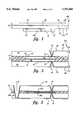
- FIG. 1is a sectional side view of a structure including a chip attached to a flexible interconnect layer.
- FIG. 2is a sectional side view of a module including two chip/flexible interconnect layer structures of the type shown in FIG. 1 which are molded together.
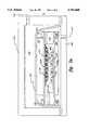
- FIG. 2ais a sectional side view illustrating a vacuum chamber fixture for forming the module illustrated in FIG. 2.
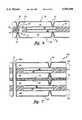
- FIG. 3is a view similar to that of FIG. 2 further showing thin chips and a metallized through via for coupling the flexible interconnect layers.
- FIG. 4is a view similar to that of FIG. 3 further showing a bend in the module.
- FIG. 5is a view similar to that of FIG. 2 further showing a plated through hole for coupling the flexible interconnect layers.
- FIG. 6is a view similar to that of FIG. 2 further showing a pin structure for coupling the flexible interconnect layers.
- FIG. 7is a view of a stack of two modules of the type shown in FIG. 2.
- FIG. 8is a view similar to that of FIG. 2 further showing an additional via and a conductive ball useful for electrical interconnection of stacked modules.
- FIG. 9is a view of a stack of two modules, one of the type shown in FIG. 8 and one of the type shown in FIG. 2.
- FIG. 1is a sectional side view of a structure 210 including a chip 10 having chip pads 12 and attached with an adhesive 14 to a chip surface 24a of a flexible interconnect layer 16.
- the flexible interconnect layercan be fabricated as described in aforementioned Cole et al. U.S. application Ser. No. 08/321,346, for example, and may comprise one or more polymer layers (shown as layers 18 and 24) which can have optional metallization layers (shown as layers 20, 26, and 26a respectively) on selected surfaces.
- an adhesive layer 22comprising a material such as SPIE (siloxane-polyimide-epoxy) or ULTEM polyetherimide (ULTEM is a trademark of General Electric Co.), for example, can be applied between the layers during lamination of layers. Lamination using SPIE is described, for example, in Gorczyca et al., U.S. Pat. No. 5,161,093, issued Nov. 3, 1992. Alternatively, if no metallization layer (such as layer 20) is present on an underside of an upper polymer layer, such upper polymer layer can be spin or spray coated over an underlying polymer layer instead of being laminated with an adhesive.
- SPIEsiloxane-polyimide-epoxy
- ULTEM polyetherimideULTEM polyetherimide
- the polymer layersmay comprise electrically insulating material upon which an electrically conductive material can adhere such as, for example, KAPTON H polyimide or KAPTON E polyimide (KAPTON is a trademark of E.I. du Pont de Nemours & Co.), APICAL AV polyimide (APICAL is a trademark of Kanegafugi Chemical Industry Company.), UPILEX polyimide (UPILEX is a trademark or UBE Industries, Ltd.), or ULTEM polyetherimide.
- KAPTON H polyimide or KAPTON E polyimideKAPTON is a trademark of E.I. du Pont de Nemours & Co.
- APICAL AV polyimideAPICAL is AV polyimide
- UPILEX polyimideUPILEX is a trademark or UBE Industries, Ltd.
- ULTEM polyetherimideULTEM polyetherimide.
- One or more of the polymer layerscan have vias (not shown) which can be metallized simultaneously as metallization layers 20 and
- the metallization lawyerscomprise a metal adhesion-promoting seed material such as titanium or SnCl 2 , followed by an electrolessly applied layer such as copper which can be coated by a thicker electroplated metal layer such as copper.
- the metallization layerscan be patterned using conventional photoresist patterning techniques, for example.
- Metallization layerscan be present on one or both surfaces of selected polymer layers. If a metallization layer such as layer 26a is on a chip side surface of a polymer layer, it can be situated over a chip but should not be situated over a chip pad to which a via would be drilled.
- the circuit chipsmay comprise integrated circuits or active or passive discrete circuit components such as those available in surface mount technology (SMT), including ultra thin silicon devices available from Kopin Corporation of Connecticut and ultra thin gallium arsenide devices available from Tacan Corporation of California, to form unique conformable multi-chip module (MCM) assemblies.
- SMTsurface mount technology
- MCMultra thin gallium arsenide devices
- MCMmulti-chip module
- Devicessuch as an ultrasonic transducer for flexible ultrasound capability or an integrated circuit chip for RADAR applications on curved surfaces of airplane wings, for example, can be useful. Further applications of thin flexible curved surfaces are described in Wojnarowski, U.S. Pat. No. 5,324,687, issued Jun. 28, 1994.
- Adhesive 14may comprise an organic adhesive such as SPIE (siloxane-polyimide-epoxy) or a cyanoacrylate and preferably has sufficient optical absorption properties to allow subsequent laser via drilling to bond pads below. Commercially available hot melt adhesives, die attach adhesives, and/or epoxies may also be used for chip bonding.
- the adhesivepreferably has appropriate dielectric properties to isolate the chip pads and chip surface from mechanical or electrical contact with any metallization layer situated between the chip and flexible interconnect structure 16 (layer 26a as shown in FIG. 1).
- a thin insulative layer(not shown) is coated on the polymer layer 24 and metallization layer 26a prior to attaching the chip, and the dielectric properties of the adhesive become less important.
- additional layerscan be used if desired.
- FIG. 2is a sectional side view of a module 212 including two structures 210 of the type shown in FIG. 1 which are molded together.
- Flexible interconnect layer 28can be fabricated and attached with an adhesive 34 to chip 30 having chip pads 32 as discussed with respect to FIG. 1.
- individual polymer and metallization layers of the structureswill not be shown in FIG. 2 and the remaining figures.
- FIG. 2ais a sectional side view illustrating a vacuum chamber technique for forming the module illustrated in FIG. 2.
- FIG. 2ashows a plurality of chips 110 on each flexible interconnect layer 116a and 116b.
- the compliant materialif used, can either be present between all chips in both flexible interconnect layers or be situated between selected chips.
- the compliant materialmay comprise a material such as SPIE or RICOCAP F 101-D encapsulant (available from Ricon Electronic Systems, Yorktown Heights, N.Y.), for example, which can withstand further processing steps.
- the compliant materialis not necessary for the present invention, it is particularly useful when one of the structures 210 has a higher chip density than the other.
- the backsides 132 of the chips in FIG. 2aare not aligned in the way that they are in FIG. 2. Although aligning the backsides of the chips is optional, such alignment further helps to balance stress on the module and leaves more space in the module for placement of vias, through holes, and/or pins, as shown and discussed below.
- the molding processoccurs in a heated vacuum fixture 126 having a vacuum chamber 131 and a pressurized gas input port 130.
- the flexible interconnect layerscan be held substantially taut by respective rings 120.
- One of the flexible interconnect layers, shown in FIG. 2a as layer 116a,can be positioned on a base plate 122 of the vacuum chamber.
- An optional template 123can then be positioned on the flexible interconnect layer for creating a molding form and serving as a spacer for controlling the height of the mold (if the chips are of an appropriate thickness, the chips themselves can serve as spacers and a mold form is not necessary).
- a pressure plate 124can then direct the other flexible interconnect layer 116b chip side down towards the chips of the bottom flexible interconnect layer.
- Molding material 142is preferably supplied in the template region by applying enough molding material over layer 116a before directing layer 116b down towards layer 116a so that when the layers are pressed together there is sufficient molding material between the layers. In an alternative, more complicated embodiment, molding material can be pushed into the space between layers 116a and 116b during processing.
- the molding materialis capable of being solidified under appropriate vacuum and temperature conditions.
- pressure plate 124 and layer 116bcan be used to squeeze the material under heat and vacuum conditions until the material flows and fills the mold.
- air pressureis supplied through port 130 to chamber 131 which includes a diaphragm 127 for preventing an outlet port 133 from releasing the pressure supplied through inlet port 130.
- the diaphragmmay comprises a flexible material such as KAPTON polyimide.
- the molding materialis a granule epoxy powder available from Rohm and Haas Co. of Philadelphia, Pa. under the name Plaskon SMT-B-1, and the molding process occurs at a temperature of 200° C. and pressure of 40 psi (pounds per square inch) for 30 minutes.
- Vias 36, shown in FIG. 2, extending to chip pads and/or metallization layers 20 and 26 (shown in FIG. 1) and outer metallization layers 38can be formed by any appropriate process.
- a preferred method of laser-drilling vias in the polymer filmis described in Eichelberger et al., U.S. Pat. No. 4,894,115, issued Jan. 16, 1990.
- the total thickness of each flexible interconnect layershould be minimized.
- Aforementioned Cole et al., U.S. application Ser. No. 08/321,346,describes a multi-step deep via fabrication technique (not shown in FIG. 2a) wherein a first step is the formation of a wide well having a bottom surface followed by the formation of a more conventional size via at the bottom of the deep well.
- the two stepscan be performed by using two mask processes, by using an excimer laser and adjusting the beam size, or by using a programmable laser with the adaptive lithograph technique.
- Outer metallization layers 38comprise electrically conductive material and can be applied using vacuum deposition, for example, by sequentially sputtering a thin layer of titanium (for adhesion purposes), sputtering a thin layer of copper, and electroplating a thicker layer of copper (typically ranging from three to ten micrometers) before being patterned with photoresist to provide the desired connections.
- an adaptive lithography systemis used to provide electrically conductive interconnections as described in Eichelberger et al., U.S. Pat. No. 4,835,704.
- vias 36 and outer metallization 38are shown as occurring after molding, these steps may occur prior to molding if desired and if appropriate protection is provided between the metallization layers and the base and pressure plates.
- An advantage to forming the vias and metallization patterns after moldingis that the surfaces of the flexible interconnect layers are relatively planar.
- FIG. 3is a view similar to that of FIG. 2 further showing thin chips 10a and 30a and a metallized through via 44 for coupling flexible interconnect layers 16 and 28.
- Via 44can be fabricated in the manner discussed with respect to vias 36.
- outer metallization layers 38are shown to extend over the flexible interconnect layers and into via 44.
- a viacan be fabricated to extend to a metallization layer of the type illustrated by metallization layers 20 and 26 in FIG. 1.
- one of the outer metallization layersis applied before the other.
- An advantage of this methodis that if via 44 is later formed by laser ablation (drilling), the earlier applied metallization layer can serve as a landing layer during the ablation process.
- FIG. 4is a view similar to that of FIG. 3 further showing a bend 50 in the modules. If chips 10a and 30a comprising thin, flexible materials are used, the chips themselves can be bent for spatial reasons such as permitting a conformal fit to a curved surface.
- FIG. 5is a view similar to that of FIG. 2 further showing a through hole 46 covered by a metallization layer 48 for coupling the flexible interconnect layers.
- the metallized through holecan be fabricated before, after, or simultaneously as vias 36 and outer metallization layers 38 are formed.
- hole 46is formed by mechanical or laser drilling. Vias 36 are formed either before or after hole 46.
- the modulecan then be dipped in a seed layer solution to create an electrically conductive seed layer which can further be thickened by processes such as electroless plating and electroplating as discussed above. If metallization of the outer metallization layers occurs simultaneously with metallization of holes 46 and if the chip pads are aluminum, a seed layer solution of palladium acetate is preferred. Otherwise, a palladium tin chloride solution is sufficient.
- the outer metallization layerscan be etched using standard photoresist processes.
- the metallization of hole 46 and of vias 36can occur as two separate steps, if desired.
- Photoresistcan be used to protect the earlier applied metallization during formation of the later applied metallization.
- This embodimentcan be used in a manner similar to a printed circuit board, especially if a hole is designed to have a height convenient for insertion of surface mount devices.
- the thermal qualities of this embodimentcan be made superior to those of a printed circuit board by choosing appropriate materials for the molding material and the flexible interconnect layers.
- FIG. 6is a view similar to that of FIG. 2 further showing a pin structure for coupling the flexible interconnect layers.
- one or more pins 52can be held in position with an adhesive (not shown) to flexible interconnect layer 28 at the same time that chips 30 are attached.
- the pinscan be staggered.
- These pinsmay comprise an electrically conductive material such as copper, nickel coated copper, or Kovar coated by nickel and then gold, for example, which is capable of withstanding molding and outer metallization layer fabrication processes.
- the pinsare wrapped in fixed arrays with a material 54 such as a polyimide, polysulfone, polyetherimide, or polytetrafluoroethylene, for ease of alignment in a module.
- the pinscan function as spacers during the process of positioning the molding material 42.
- pins 52 and material 54can be designed to extend contiguously at the boundary of a module and thereby additionally serve as a molding form.
- FIG. 7is a view of a stack 214 of two modules 212 of the type shown in FIG. 2.
- the stackis useful for forming a three-dimensional mass memory structure.
- a second modulecan be fabricated with flexible interconnect layers 62 and 64, respective chips 58 and 60, and molding material 66 in the same manner as discussed with respect to the module shown in FIG. 2.
- FIG. 7is shown as including two modules of the type shown in FIG. 2, the process is equally applicable to the modules shown in FIGS. 3-6.
- two modulesare illustrated in the stack for example only; additional modules can be stacked.
- the modulescan be stacked in any appropriate manner.
- bonding material 74comprising an adhesive material such as an epoxy, SPIE, for example, is inserted between adjacent modules.
- the vacuum chamber shown in FIG. 2a and material similar to that of molding material 42can be used.
- a through hole 70is shown as extending through the stack. If the hole extends through metallization, a mechanical drill is preferably used to form the hole. The hole can be metallized in the manner described with respect to FIG. 5. If the hole extends through intermediate layers of metallization 38, good contact can be made between through hole metallization 38a and metallization layers 38 by dipping and electroplating the stack as discussed with respect to FIG. 5.
- FIG. 8is a view similar to that of FIG. 2 further showing an additional via 311 and a conductive ball 310 useful for electrical interconnection of stacked modules.
- module 212acan be fabricated in the same manner as discussed with respect to module 212 of FIG. 2.
- conductive ball 310can be positioned in via 36 if desired.
- Conductive ball 310Prior to the insertion of conductive ball 310, an adhesive layer 314 comprising a material such as an epoxy solder mask is applied and patterned, and a conductive material 312 such as silver epoxy is positioned in the via. The conductive ball can then be inserted in the via.
- Conductive ball 310may comprise a metal ball or a metallized ball which is capable of forming a good contact with conductive material 312.
- the metal or metallization of the conductive ballmay comprise titanium, lead, or copper.
- the conductive ballextends upward from the via for ease of stacking.
- FIG. 9is a view of a stack of two modules, one 212a of the type shown in FIG. 8 and one 212 of the type shown in FIG. 2.
- An adhesive layer 315 and conductive material 316can be applied to module 212. If the combination of adhesive layers 314 and 316 is sufficiently thick, an upper module can be positioned over the lower such that a selected via (including conductive material 316) of the upper module at least partially surrounds the upward extending portion of conductive ball 310. After conductive ball 310 is surrounded, adhesive layers 314 and 315 and conductive materials 312 and 316 can be hardened simultaneously.
Landscapes
- Engineering & Computer Science (AREA)
- Microelectronics & Electronic Packaging (AREA)
- Power Engineering (AREA)
- Computer Hardware Design (AREA)
- Physics & Mathematics (AREA)
- Condensed Matter Physics & Semiconductors (AREA)
- General Physics & Mathematics (AREA)
- Manufacturing & Machinery (AREA)
- Production Of Multi-Layered Print Wiring Board (AREA)
Abstract
Description
This application is a division of application Ser. No. 08/567,386, filed Dec. 4, 1995, now U.S. Pat. No. 5,567,651.
In one form of high density interconnect (HDI) circuit module, an adhesive-coated polymer film overlay having via openings covers a plurality of integrated circuit chips in chip wells on an underlying substrate. The polymer film provides an insulated layer upon which is deposited a metallization pattern for interconnection of individual circuit chips through the vias. Methods for performing a HDI process using overlays are further described in Eichelberger et al., U.S. Pat. No. 4,783,695, issued Nov. 8, 1988, and in Eichelberger et al., U.S. Pat. No. 4,933,042, issued Jun. 12, 1990. Multiple layers of polymer overlays and metallization patterns are typically applied, and significant processing steps are required to complete these multilayer interconnects.
Prefabricated flexible interconnect layers having metallization patterns thereon are manufactured by companies such as Sheldahl Corp., Northfield, Minn., and Padex Corp., Methuen, Mass., for example. Multichip module and other electronic assembly manufacturers conventionally couple integrated circuit chips and other components to the metallization patterns using mechanical assembly attaching techniques such as wire bonding, tape automated bonding, or solder bumps. A prefabricated flexible interconnect structure typically has at least one insulative film layer having a thickness sufficient to support metallization patterns on each side. The thickness is often between 1 to 5 mils (25 to 125 microns).
Cole et al., "Fabrication and Structures of Circuit Modules with Flexible Interconnect Layers," U.S. application Ser. No. 08/321,346, filed Oct. 11, 1994, describes a method for fabricating a circuit module using a flexible interconnect layer including a metallized base insulative layer and an outer insulative layer. At least one circuit chip having chip pads is attached to the base insulative layer and vias are formed in the outer and base insulative layers to expose selected portions of the base insulative layer metallization and the chip pads. A patterned outer metallization layer is applied over the outer insulative layer extending through selected ones of the vias to interconnect selected ones of the chip pads and selected portions of the base insulative layer metallization.
The technique described in Cole et al. can lower the volume and weight of a circuit module. Because the coefficient of thermal expansion (CTE) of the chips is generally much less that the CTE of the flexible interconnect layer, however, if the area density of chips on the flexible interconnect layer is too high, unbalanced stresses and associated warping can occur.
It would be desirable to balance module stresses and further increase density while maintaining the low volume and weight of flexible high density interconnect circuit modules and enabling efficient fabrication processes.
Briefly, in accordance with one embodiment of the invention a method for fabricating a circuit module comprises providing first and second flexible interconnect structures with each flexible interconnect structure comprising a flexible interconnect layer and a chip with a surface having chip pads attached to the flexible interconnect layer. Molding material is inserted between the flexible interconnect layers for encapsulating the respective chips. Vias in the flexible interconnect layers are formed to extend to selected chip pads, and a pattern of electrical conductors is applied which extends over the flexible interconnect layers and into the vias to couple selected ones of the chip pads.
The features of the invention believed to be novel are set forth with particularity in the appended claims. The invention itself, however, both as to organization and method of operation, together with further objects and advantages thereof, may best be understood by reference to the following description taken in conjunction with the accompanying drawings, where like numerals represent like components, in which:
FIG. 1 is a sectional side view of a structure including a chip attached to a flexible interconnect layer.
FIG. 2 is a sectional side view of a module including two chip/flexible interconnect layer structures of the type shown in FIG. 1 which are molded together.
FIG. 2a is a sectional side view illustrating a vacuum chamber fixture for forming the module illustrated in FIG. 2.
FIG. 3 is a view similar to that of FIG. 2 further showing thin chips and a metallized through via for coupling the flexible interconnect layers.
FIG. 4 is a view similar to that of FIG. 3 further showing a bend in the module.
FIG. 5 is a view similar to that of FIG. 2 further showing a plated through hole for coupling the flexible interconnect layers.
FIG. 6 is a view similar to that of FIG. 2 further showing a pin structure for coupling the flexible interconnect layers.
FIG. 7 is a view of a stack of two modules of the type shown in FIG. 2.
FIG. 8 is a view similar to that of FIG. 2 further showing an additional via and a conductive ball useful for electrical interconnection of stacked modules.
FIG. 9 is a view of a stack of two modules, one of the type shown in FIG. 8 and one of the type shown in FIG. 2.
FIG. 1 is a sectional side view of astructure 210 including achip 10 havingchip pads 12 and attached with anadhesive 14 to achip surface 24a of aflexible interconnect layer 16. The flexible interconnect layer can be fabricated as described in aforementioned Cole et al. U.S. application Ser. No. 08/321,346, for example, and may comprise one or more polymer layers (shown aslayers 18 and 24) which can have optional metallization layers (shown aslayers adhesive layer 22 comprising a material such as SPIE (siloxane-polyimide-epoxy) or ULTEM polyetherimide (ULTEM is a trademark of General Electric Co.), for example, can be applied between the layers during lamination of layers. Lamination using SPIE is described, for example, in Gorczyca et al., U.S. Pat. No. 5,161,093, issued Nov. 3, 1992. Alternatively, if no metallization layer (such as layer 20) is present on an underside of an upper polymer layer, such upper polymer layer can be spin or spray coated over an underlying polymer layer instead of being laminated with an adhesive.
The polymer layers may comprise electrically insulating material upon which an electrically conductive material can adhere such as, for example, KAPTON H polyimide or KAPTON E polyimide (KAPTON is a trademark of E.I. du Pont de Nemours & Co.), APICAL AV polyimide (APICAL is a trademark of Kanegafugi Chemical Industry Company.), UPILEX polyimide (UPILEX is a trademark or UBE Industries, Ltd.), or ULTEM polyetherimide. One or more of the polymer layers can have vias (not shown) which can be metallized simultaneously asmetallization layers
In one embodiment, the metallization lawyers comprise a metal adhesion-promoting seed material such as titanium or SnCl2, followed by an electrolessly applied layer such as copper which can be coated by a thicker electroplated metal layer such as copper. The metallization layers can be patterned using conventional photoresist patterning techniques, for example. Metallization layers can be present on one or both surfaces of selected polymer layers. If a metallization layer such aslayer 26a is on a chip side surface of a polymer layer, it can be situated over a chip but should not be situated over a chip pad to which a via would be drilled.
The circuit chips may comprise integrated circuits or active or passive discrete circuit components such as those available in surface mount technology (SMT), including ultra thin silicon devices available from Kopin Corporation of Connecticut and ultra thin gallium arsenide devices available from Tacan Corporation of California, to form unique conformable multi-chip module (MCM) assemblies. Devices such as an ultrasonic transducer for flexible ultrasound capability or an integrated circuit chip for RADAR applications on curved surfaces of airplane wings, for example, can be useful. Further applications of thin flexible curved surfaces are described in Wojnarowski, U.S. Pat. No. 5,324,687, issued Jun. 28, 1994.
Adhesive 14 may comprise an organic adhesive such as SPIE (siloxane-polyimide-epoxy) or a cyanoacrylate and preferably has sufficient optical absorption properties to allow subsequent laser via drilling to bond pads below. Commercially available hot melt adhesives, die attach adhesives, and/or epoxies may also be used for chip bonding. The adhesive preferably has appropriate dielectric properties to isolate the chip pads and chip surface from mechanical or electrical contact with any metallization layer situated between the chip and flexible interconnect structure 16 (layer 26a as shown in FIG. 1). In one embodiment, a thin insulative layer (not shown) is coated on thepolymer layer 24 andmetallization layer 26a prior to attaching the chip, and the dielectric properties of the adhesive become less important. Although two polymer layers are shown in FIG. 1, additional layers can be used if desired.
FIG. 2 is a sectional side view of amodule 212 including twostructures 210 of the type shown in FIG. 1 which are molded together.Flexible interconnect layer 28 can be fabricated and attached with an adhesive 34 to chip 30 havingchip pads 32 as discussed with respect to FIG. 1. For simplicity, individual polymer and metallization layers of the structures will not be shown in FIG. 2 and the remaining figures.
FIG. 2a is a sectional side view illustrating a vacuum chamber technique for forming the module illustrated in FIG. 2. For illustrative purposes, FIG. 2a shows a plurality ofchips 110 on eachflexible interconnect layer 116a and 116b. When a plurality of chips are used on a flexible interconnect layer, it is useful to position optionalcompliant material 118 between adjacent chips to balance stress on the structure as shown by the compliant material between the chips attached to flexible interconnect layer 116b. The compliant material, if used, can either be present between all chips in both flexible interconnect layers or be situated between selected chips.
The compliant material may comprise a material such as SPIE or RICOCAP F 101-D encapsulant (available from Ricon Electronic Systems, Yorktown Heights, N.Y.), for example, which can withstand further processing steps. Although the compliant material is not necessary for the present invention, it is particularly useful when one of thestructures 210 has a higher chip density than the other.
Thebacksides 132 of the chips in FIG. 2a are not aligned in the way that they are in FIG. 2. Although aligning the backsides of the chips is optional, such alignment further helps to balance stress on the module and leaves more space in the module for placement of vias, through holes, and/or pins, as shown and discussed below.
In one embodiment the molding process occurs in aheated vacuum fixture 126 having avacuum chamber 131 and a pressurizedgas input port 130. The flexible interconnect layers can be held substantially taut byrespective rings 120. One of the flexible interconnect layers, shown in FIG. 2a aslayer 116a, can be positioned on abase plate 122 of the vacuum chamber. Anoptional template 123 can then be positioned on the flexible interconnect layer for creating a molding form and serving as a spacer for controlling the height of the mold (if the chips are of an appropriate thickness, the chips themselves can serve as spacers and a mold form is not necessary). Apressure plate 124 can then direct the other flexible interconnect layer 116b chip side down towards the chips of the bottom flexible interconnect layer.
Preferably the molding material is capable of being solidified under appropriate vacuum and temperature conditions. After the material is inserted overlayer 116a,pressure plate 124 and layer 116b can be used to squeeze the material under heat and vacuum conditions until the material flows and fills the mold. In one embodiment, air pressure is supplied throughport 130 tochamber 131 which includes adiaphragm 127 for preventing anoutlet port 133 from releasing the pressure supplied throughinlet port 130. The diaphragm may comprises a flexible material such as KAPTON polyimide.
Excess molding material can escape through flow-outports 128. In one embodiment, the molding material is a granule epoxy powder available from Rohm and Haas Co. of Philadelphia, Pa. under the name Plaskon SMT-B-1, and the molding process occurs at a temperature of 200° C. and pressure of 40 psi (pounds per square inch) for 30 minutes.
Other molding techniques and materials which may be appropriate are discussed in Fillion et al., U.S. Pat. No. 5,353,498, issued Oct. 11, 1994, and in Gorczyca, "Solventless Process for Fabricating Polyimide/Epoxy Plastic Molded Parts," U.S. Application No. 08/265,051, filed Jun. 24, 1994, which is a continuation in part of U.S. application Ser. No. 08/143,519, filed Oct. 29, 1993.
Aforementioned Cole et al., U.S. application Ser. No. 08/321,346, describes a multi-step deep via fabrication technique (not shown in FIG. 2a) wherein a first step is the formation of a wide well having a bottom surface followed by the formation of a more conventional size via at the bottom of the deep well. The two steps can be performed by using two mask processes, by using an excimer laser and adjusting the beam size, or by using a programmable laser with the adaptive lithograph technique.
Outer metallization layers 38 comprise electrically conductive material and can be applied using vacuum deposition, for example, by sequentially sputtering a thin layer of titanium (for adhesion purposes), sputtering a thin layer of copper, and electroplating a thicker layer of copper (typically ranging from three to ten micrometers) before being patterned with photoresist to provide the desired connections. In one embodiment an adaptive lithography system is used to provide electrically conductive interconnections as described in Eichelberger et al., U.S. Pat. No. 4,835,704. Although the formation ofvias 36 andouter metallization 38 is shown as occurring after molding, these steps may occur prior to molding if desired and if appropriate protection is provided between the metallization layers and the base and pressure plates. An advantage to forming the vias and metallization patterns after molding is that the surfaces of the flexible interconnect layers are relatively planar.
FIG. 3 is a view similar to that of FIG. 2 further showingthin chips vias 36. In this embodiment, outer metallization layers 38 are shown to extend over the flexible interconnect layers and into via 44. In another embodiment, a via can be fabricated to extend to a metallization layer of the type illustrated bymetallization layers
FIG. 4 is a view similar to that of FIG. 3 further showing abend 50 in the modules. Ifchips
FIG. 5 is a view similar to that of FIG. 2 further showing a throughhole 46 covered by ametallization layer 48 for coupling the flexible interconnect layers. The metallized through hole can be fabricated before, after, or simultaneously asvias 36 and outer metallization layers 38 are formed.
In one embodiment, before outer metallization layers are formed,hole 46 is formed by mechanical or laser drilling.Vias 36 are formed either before or afterhole 46. The module can then be dipped in a seed layer solution to create an electrically conductive seed layer which can further be thickened by processes such as electroless plating and electroplating as discussed above. If metallization of the outer metallization layers occurs simultaneously with metallization ofholes 46 and if the chip pads are aluminum, a seed layer solution of palladium acetate is preferred. Otherwise, a palladium tin chloride solution is sufficient. The outer metallization layers can be etched using standard photoresist processes.
Alternatively, the metallization ofhole 46 and ofvias 36 can occur as two separate steps, if desired. Photoresist can be used to protect the earlier applied metallization during formation of the later applied metallization.
This embodiment can be used in a manner similar to a printed circuit board, especially if a hole is designed to have a height convenient for insertion of surface mount devices. The thermal qualities of this embodiment can be made superior to those of a printed circuit board by choosing appropriate materials for the molding material and the flexible interconnect layers.
FIG. 6 is a view similar to that of FIG. 2 further showing a pin structure for coupling the flexible interconnect layers. In one embodiment, one ormore pins 52 can be held in position with an adhesive (not shown) toflexible interconnect layer 28 at the same time that chips 30 are attached. As shown bypins molding material 42. Moreover, pins 52 andmaterial 54 can be designed to extend contiguously at the boundary of a module and thereby additionally serve as a molding form.
FIG. 7 is a view of astack 214 of twomodules 212 of the type shown in FIG. 2. The stack is useful for forming a three-dimensional mass memory structure. A second module can be fabricated with flexible interconnect layers 62 and 64,respective chips molding material 66 in the same manner as discussed with respect to the module shown in FIG. 2. Although FIG. 7 is shown as including two modules of the type shown in FIG. 2, the process is equally applicable to the modules shown in FIGS. 3-6. Furthermore, two modules are illustrated in the stack for example only; additional modules can be stacked.
The modules can be stacked in any appropriate manner. In oneembodiment bonding material 74 comprising an adhesive material such as an epoxy, SPIE, for example, is inserted between adjacent modules. In another embodiment, if desired, the vacuum chamber shown in FIG. 2a and material similar to that ofmolding material 42 can be used.
Electrical interconnection of modules in a stack can be made using techniques similar to those discussed above for coupling structures within a module. In FIG. 7, a throughhole 70 is shown as extending through the stack. If the hole extends through metallization, a mechanical drill is preferably used to form the hole. The hole can be metallized in the manner described with respect to FIG. 5. If the hole extends through intermediate layers ofmetallization 38, good contact can be made between throughhole metallization 38a andmetallization layers 38 by dipping and electroplating the stack as discussed with respect to FIG. 5.
FIG. 8 is a view similar to that of FIG. 2 further showing an additional via 311 and aconductive ball 310 useful for electrical interconnection of stacked modules. In the embodiment of FIG. 8,module 212a can be fabricated in the same manner as discussed with respect tomodule 212 of FIG. 2. Although an extra via 311 (which can be fabricated in the same manner as via 36) is shown in FIG. 8,conductive ball 310 can be positioned in via 36 if desired.
Prior to the insertion ofconductive ball 310, anadhesive layer 314 comprising a material such as an epoxy solder mask is applied and patterned, and aconductive material 312 such as silver epoxy is positioned in the via. The conductive ball can then be inserted in the via.Conductive ball 310 may comprise a metal ball or a metallized ball which is capable of forming a good contact withconductive material 312. For example, the metal or metallization of the conductive ball may comprise titanium, lead, or copper. Preferably the conductive ball extends upward from the via for ease of stacking.
FIG. 9 is a view of a stack of two modules, one 212a of the type shown in FIG. 8 and one 212 of the type shown in FIG. 2. Anadhesive layer 315 andconductive material 316 can be applied tomodule 212. If the combination ofadhesive layers conductive ball 310. Afterconductive ball 310 is surrounded,adhesive layers conductive materials
While only certain preferred features of the invention have been illustrated and described herein, many modifications and changes will occur to those skilled in the art. It is, therefore, to be understood that the appended claims are intended to cover all such modifications and changes as fall within the true spirit of the invention.
Claims (9)
1. A two-sided molded circuit module with flexible interconnect layers, the module comprising:
first and second flexible interconnect structures, each flexible interconnect structure comprising a flexible interconnect layer having a chip surface and at least one chip with chip pads attached to the chip surface, the chip surface of the first flexible interconnect structure facing the chip surface of the second interconnect structure;
molding material between the chip surfaces of the flexible interconnect layers encapsulating each of the at least one chips;
vias in the flexible interconnect layers, at least some of the vias extending to selected chip pads;
a pattern of electrical conductors extending over the flexible interconnect layers and into the vias to couple selected ones of the chip pads.
2. The module of claim 1, further including a deep via extending through one of the flexible interconnect structures and the molding material to the other of the flexible interconnect structures, and wherein the pattern of electrical conductors extends into the deep via.
3. The module of claim 1, wherein each flexible interconnect layer comprises a plurality of polymer layers and at least one patterned metallization layer.
4. The module of claim 1, further including a hole extending through the flexible interconnect structures and the molding material and coated with an electrically conductive coating material.
5. The module of claim 4, wherein the electrically conductive coating material comprises a portion of the pattern of electrical conductors.
6. The module of claim 1, further including at least one electrically conductive pin coupled between the first and second flexible interconnect structures and encapsulated by the molding material, and wherein a pin via extends through one of the flexible interconnect structures and the pattern of electrical conductors extends into the pin via.
7. A stack of two-sided molded circuit modules with flexible interconnect layers, the stack comprising:
a plurality of circuit modules, each circuit module comprising first and second flexible interconnect structures, each flexible interconnect structure comprising a flexible interconnect layer having a chip surface and at least one chip with chip pads attached to the chip surface, the chip surface of the first flexible interconnect structure facing the chip surface of the second interconnect structure, molding material between the chip surfaces of the flexible interconnect layers encapsulating each of the at least one chips, vias in at least one of the flexible interconnect layers, at least one of the vias extending to a chip pad, and a pattern of electrical conductors extending over the at least one of the flexible interconnect layers and into the vias; and
bonding material between adjacent ones of the circuit modules.
8. The stack of claim 7, further including means for coupling a pattern of electrical conductors of one of the circuit modules with a pattern of electrical conductors of another of the circuit modules.
9. The stack of claim 8, wherein the means for coupling includes a conductive ball, a first portion of the conductive ball situated in a via of the one of the circuit modules and a second portion of the conductive ball situated in a via of the another of the circuit modules.
Priority Applications (1)
| Application Number | Priority Date | Filing Date | Title |
|---|---|---|---|
| US08/684,715US5703400A (en) | 1995-12-04 | 1996-07-22 | Fabrication and structures of two-sided molded circuit modules with flexible interconnect layers |
Applications Claiming Priority (2)
| Application Number | Priority Date | Filing Date | Title |
|---|---|---|---|
| US08/567,386US5567657A (en) | 1995-12-04 | 1995-12-04 | Fabrication and structures of two-sided molded circuit modules with flexible interconnect layers |
| US08/684,715US5703400A (en) | 1995-12-04 | 1996-07-22 | Fabrication and structures of two-sided molded circuit modules with flexible interconnect layers |
Related Parent Applications (1)
| Application Number | Title | Priority Date | Filing Date |
|---|---|---|---|
| US08/567,386DivisionUS5567657A (en) | 1995-12-04 | 1995-12-04 | Fabrication and structures of two-sided molded circuit modules with flexible interconnect layers |
Publications (1)
| Publication Number | Publication Date |
|---|---|
| US5703400Atrue US5703400A (en) | 1997-12-30 |
Family
ID=24266947
Family Applications (2)
| Application Number | Title | Priority Date | Filing Date |
|---|---|---|---|
| US08/567,386Expired - LifetimeUS5567657A (en) | 1995-12-04 | 1995-12-04 | Fabrication and structures of two-sided molded circuit modules with flexible interconnect layers |
| US08/684,715Expired - LifetimeUS5703400A (en) | 1995-12-04 | 1996-07-22 | Fabrication and structures of two-sided molded circuit modules with flexible interconnect layers |
Family Applications Before (1)
| Application Number | Title | Priority Date | Filing Date |
|---|---|---|---|
| US08/567,386Expired - LifetimeUS5567657A (en) | 1995-12-04 | 1995-12-04 | Fabrication and structures of two-sided molded circuit modules with flexible interconnect layers |
Country Status (1)
| Country | Link |
|---|---|
| US (2) | US5567657A (en) |
Cited By (97)
| Publication number | Priority date | Publication date | Assignee | Title |
|---|---|---|---|---|
| US5888884A (en)* | 1998-01-02 | 1999-03-30 | General Electric Company | Electronic device pad relocation, precision placement, and packaging in arrays |
| US6049467A (en)* | 1998-08-31 | 2000-04-11 | Unisys Corporation | Stackable high density RAM modules |
| US6154366A (en)* | 1999-11-23 | 2000-11-28 | Intel Corporation | Structures and processes for fabricating moisture resistant chip-on-flex packages |
| US6187652B1 (en)* | 1998-09-14 | 2001-02-13 | Fujitsu Limited | Method of fabrication of multiple-layer high density substrate |
| US6239482B1 (en) | 1999-06-21 | 2001-05-29 | General Electric Company | Integrated circuit package including window frame |
| US6242282B1 (en)* | 1999-10-04 | 2001-06-05 | General Electric Company | Circuit chip package and fabrication method |
| US6265771B1 (en)* | 1999-01-27 | 2001-07-24 | International Business Machines Corporation | Dual chip with heat sink |
| US6271469B1 (en) | 1999-11-12 | 2001-08-07 | Intel Corporation | Direct build-up layer on an encapsulated die package |
| US20020070443A1 (en)* | 2000-12-08 | 2002-06-13 | Xiao-Chun Mu | Microelectronic package having an integrated heat sink and build-up layers |
| US6410937B1 (en)* | 1998-12-08 | 2002-06-25 | Alexsander Ivanovich Taran | Integrated circuit chip carrier |
| US6423570B1 (en) | 2000-10-18 | 2002-07-23 | Intel Corporation | Method to protect an encapsulated die package during back grinding with a solder metallization layer and devices formed thereby |
| US20020158334A1 (en)* | 2001-04-30 | 2002-10-31 | Intel Corporation | Microelectronic device having signal distribution functionality on an interfacial layer thereof |
| US20020158335A1 (en)* | 2001-04-30 | 2002-10-31 | Intel Corporation | High performance, low cost microelectronic circuit package with interposer |
| US20020173133A1 (en)* | 2001-05-21 | 2002-11-21 | Intel Corporation | Method for packaging a microelectronic device using on-die bond pad expansion |
| US20020175402A1 (en)* | 2001-05-23 | 2002-11-28 | Mccormack Mark Thomas | Structure and method of embedding components in multi-layer substrates |
| US6489185B1 (en) | 2000-09-13 | 2002-12-03 | Intel Corporation | Protective film for the fabrication of direct build-up layers on an encapsulated die package |
| US6555906B2 (en) | 2000-12-15 | 2003-04-29 | Intel Corporation | Microelectronic package having a bumpless laminated interconnection layer |
| US20030094704A1 (en)* | 2001-01-26 | 2003-05-22 | Gann Keith D. | Method of fabricating known good dies from packaged integrated circuits |
| US6586822B1 (en) | 2000-09-08 | 2003-07-01 | Intel Corporation | Integrated core microelectronic package |
| US6586276B2 (en)* | 2001-07-11 | 2003-07-01 | Intel Corporation | Method for fabricating a microelectronic device using wafer-level adhesion layer deposition |
| US6586836B1 (en) | 2000-03-01 | 2003-07-01 | Intel Corporation | Process for forming microelectronic packages and intermediate structures formed therewith |
| US6590291B2 (en)* | 2000-01-31 | 2003-07-08 | Shinko Electric Industries Co., Ltd. | Semiconductor device and manufacturing method therefor |
| US6624505B2 (en) | 1998-02-06 | 2003-09-23 | Shellcase, Ltd. | Packaged integrated circuits and methods of producing thereof |
| US20030221313A1 (en)* | 2001-01-26 | 2003-12-04 | Gann Keith D. | Method for making stacked integrated circuits (ICs) using prepackaged parts |
| US6709898B1 (en) | 2000-10-04 | 2004-03-23 | Intel Corporation | Die-in-heat spreader microelectronic package |
| US6713859B1 (en) | 2000-09-13 | 2004-03-30 | Intel Corporation | Direct build-up layer on an encapsulated die package having a moisture barrier structure |
| US6734534B1 (en) | 2000-08-16 | 2004-05-11 | Intel Corporation | Microelectronic substrate with integrated devices |
| US6759316B2 (en)* | 1998-08-18 | 2004-07-06 | Oki Electric Industry Co., Ltd. | Method of manufacturing a semiconductor chip |
| US20040145063A1 (en)* | 2003-01-29 | 2004-07-29 | Sutherland Ivan E. | Integrated circuit assembly module that supports capacitive communication between semiconductor dies |
| US20040183185A1 (en)* | 1998-02-06 | 2004-09-23 | Avner Badihi | Packaged integrated circuits and methods of producing thereof |
| US20040251525A1 (en)* | 2003-06-16 | 2004-12-16 | Shellcase Ltd. | Methods and apparatus for packaging integrated circuit devices |
| US20050029644A1 (en)* | 2003-08-08 | 2005-02-10 | Kwun-Yao Ho | [multi-chip package and manufacturing method thereof] |
| US20050062173A1 (en)* | 2000-08-16 | 2005-03-24 | Intel Corporation | Microelectronic substrates with integrated devices |
| US20050104179A1 (en)* | 2003-07-03 | 2005-05-19 | Shellcase Ltd. | Methods and apparatus for packaging integrated circuit devices |
| US7033664B2 (en) | 2002-10-22 | 2006-04-25 | Tessera Technologies Hungary Kft | Methods for producing packaged integrated circuit devices and packaged integrated circuit devices produced thereby |
| US20060278976A1 (en)* | 2004-09-02 | 2006-12-14 | Koninklijke Phillips Electronics N.C. | Semiconductor device, method and manufacturing same, identification label and information carrier |
| US20070034777A1 (en)* | 2005-08-12 | 2007-02-15 | Tessera, Inc. | Image sensor employing a plurality of photodetector arrays and/or rear-illuminated architecture |
| US20070040180A1 (en)* | 1998-02-06 | 2007-02-22 | Tessera Technologies Hungary Kft. | Integrated circuit device |
| US7183658B2 (en) | 2001-09-05 | 2007-02-27 | Intel Corporation | Low cost microelectronic circuit package |
| US7224056B2 (en) | 2003-09-26 | 2007-05-29 | Tessera, Inc. | Back-face and edge interconnects for lidded package |
| US20070152320A1 (en)* | 2003-06-13 | 2007-07-05 | Osamu Yamagata | Semiconductor device, package structure thereof, and method for manufacturing the semiconductor device |
| US20070241443A1 (en)* | 2006-04-13 | 2007-10-18 | Inapac Technology, Inc. | Isolating electric paths in semiconductor device packages |
| US20070254475A1 (en)* | 2004-02-17 | 2007-11-01 | Sanyo Electric Co., Ltd. | Semiconductor device with a barrier layer and a metal layer |
| US20080094805A1 (en)* | 2004-11-26 | 2008-04-24 | Imbera Electroics Oy | Electronics Module and Method for Manufacturing the Same |
| US20080283996A1 (en)* | 2007-05-15 | 2008-11-20 | Samsung Electronics Co., Ltd. | Semiconductor package using chip-embedded interposer substrate |
| US20090034370A1 (en)* | 2007-08-03 | 2009-02-05 | Xiaocong Guo | Diagnostic ultrasound transducer |
| EP2056349A1 (en)* | 2001-10-18 | 2009-05-06 | Panasonic Corporation | Component built-in module and method for producing the same |
| US20090155954A1 (en)* | 2005-04-21 | 2009-06-18 | Industrial Technology Research Institute | Thermal enhanced low profile package structure and method for fabricating the same |
| US7566955B2 (en) | 2001-08-28 | 2009-07-28 | Tessera, Inc. | High-frequency chip packages |
| US20090194885A1 (en)* | 2008-01-31 | 2009-08-06 | Casio Computer Co., Ltd. | Semiconductor device having wiring line and manufacturing method thereof |
| US20090194866A1 (en)* | 2008-01-31 | 2009-08-06 | Casio Computer Co., Ltd. | Semiconductor device having wiring line and manufacturing method thereof |
| US20090309241A1 (en)* | 2008-06-13 | 2009-12-17 | General Electric Company | Ultra thin die electronic package |
| US20100224992A1 (en)* | 2009-03-06 | 2010-09-09 | Mcconnelee Paul Alan | System and method for stacked die embedded chip build-up |
| US20100258937A1 (en)* | 2007-12-14 | 2010-10-14 | Stats Chippac, Ltd. | Semiconductor Device and Method of Forming Interconnect Structure for Encapsulated Die Having Pre-Applied Protective Layer |
| US20100301473A1 (en)* | 2007-11-01 | 2010-12-02 | Dai Nippon Printing Co., Ltd. | Component built-in wiring board and manufacturing method of component built-in wiring board |
| US20110016352A1 (en)* | 2008-04-09 | 2011-01-20 | Rambus Inc. | Programmable memory repair scheme |
| US7936062B2 (en) | 2006-01-23 | 2011-05-03 | Tessera Technologies Ireland Limited | Wafer level chip packaging |
| US8035213B2 (en) | 2007-10-22 | 2011-10-11 | Advanced Semiconductor Engineering, Inc. | Chip package structure and method of manufacturing the same |
| US8110916B2 (en) | 2009-06-19 | 2012-02-07 | Advanced Semiconductor Engineering, Inc. | Chip package structure and manufacturing methods thereof |
| US8143095B2 (en) | 2005-03-22 | 2012-03-27 | Tessera, Inc. | Sequential fabrication of vertical conductive interconnects in capped chips |
| US8193647B2 (en) | 2009-07-21 | 2012-06-05 | Advanced Semiconductor Engineering, Inc. | Semiconductor device package with an alignment mark |
| US8278746B2 (en) | 2010-04-02 | 2012-10-02 | Advanced Semiconductor Engineering, Inc. | Semiconductor device packages including connecting elements |
| US8286046B2 (en) | 2001-09-28 | 2012-10-09 | Rambus Inc. | Integrated circuit testing module including signal shaping interface |
| US8320134B2 (en) | 2010-02-05 | 2012-11-27 | Advanced Semiconductor Engineering, Inc. | Embedded component substrate and manufacturing methods thereof |
| US8358001B2 (en) | 2009-07-23 | 2013-01-22 | Advanced Semiconductor Engineering, Inc. | Semiconductor device packages, redistribution structures, and manufacturing methods thereof |
| US8372689B2 (en) | 2010-01-21 | 2013-02-12 | Advanced Semiconductor Engineering, Inc. | Wafer-level semiconductor device packages with three-dimensional fan-out and manufacturing methods thereof |
| US8378466B2 (en) | 2009-11-19 | 2013-02-19 | Advanced Semiconductor Engineering, Inc. | Wafer-level semiconductor device packages with electromagnetic interference shielding |
| US8405213B2 (en) | 2010-03-22 | 2013-03-26 | Advanced Semiconductor Engineering, Inc. | Semiconductor package including a stacking element |
| US8569894B2 (en) | 2010-01-13 | 2013-10-29 | Advanced Semiconductor Engineering, Inc. | Semiconductor package with single sided substrate design and manufacturing methods thereof |
| US8604605B2 (en) | 2007-01-05 | 2013-12-10 | Invensas Corp. | Microelectronic assembly with multi-layer support structure |
| US8624374B2 (en) | 2010-04-02 | 2014-01-07 | Advanced Semiconductor Engineering, Inc. | Semiconductor device packages with fan-out and with connecting elements for stacking and manufacturing methods thereof |
| US8658473B2 (en) | 2012-03-27 | 2014-02-25 | General Electric Company | Ultrathin buried die module and method of manufacturing thereof |
| US8717052B2 (en) | 2002-11-27 | 2014-05-06 | Rambus Inc. | Testing fuse configurations in semiconductor devices |
| US8749042B2 (en) | 2006-04-11 | 2014-06-10 | Rambus Inc. | Process for making a semiconductor system |
| US8786100B2 (en) | 2010-03-15 | 2014-07-22 | Stats Chippac, Ltd. | Semiconductor device and method of forming repassivation layer with reduced opening to contact pad of semiconductor die |
| US8907476B2 (en) | 2010-03-12 | 2014-12-09 | Stats Chippac, Ltd. | Semiconductor device and method of forming sacrificial protective layer to protect semiconductor die edge during singulation |
| US8941222B2 (en) | 2010-11-11 | 2015-01-27 | Advanced Semiconductor Engineering Inc. | Wafer level semiconductor package and manufacturing methods thereof |
| US9153508B2 (en) | 2011-08-17 | 2015-10-06 | Rambus Inc. | Multi-chip package and interposer with signal line compression |
| US9153552B2 (en)* | 2012-09-28 | 2015-10-06 | Intel Corporation | Bumpless build-up layer package including an integrated heat spreader |
| US9159690B2 (en) | 2013-09-25 | 2015-10-13 | Intel Corporation | Tall solders for through-mold interconnect |
| US20160049316A1 (en)* | 2013-01-07 | 2016-02-18 | Intel Corporation | Embedded package in pcb build up |
| US9269701B2 (en) | 2012-09-28 | 2016-02-23 | Intel Corporation | Localized high density substrate routing |
| US9318441B2 (en) | 2007-12-14 | 2016-04-19 | Stats Chippac, Ltd. | Semiconductor device and method of forming sacrificial adhesive over contact pads of semiconductor die |
| US9349703B2 (en) | 2013-09-25 | 2016-05-24 | Intel Corporation | Method for making high density substrate interconnect using inkjet printing |
| US9406658B2 (en) | 2010-12-17 | 2016-08-02 | Advanced Semiconductor Engineering, Inc. | Embedded component device and manufacturing methods thereof |
| US9437569B2 (en) | 2012-12-06 | 2016-09-06 | Intel Corporation | High density substrate routing in BBUL package |
| US20160260652A1 (en)* | 2014-08-01 | 2016-09-08 | Linear Technology Corporation | Laser drilling encapsulated semiconductor die to expose electrical connection therein |
| US9548240B2 (en) | 2010-03-15 | 2017-01-17 | STATS ChipPAC Pte. Ltd. | Semiconductor device and method of forming repassivation layer for robust low cost fan-out semiconductor package |
| US9564346B2 (en) | 2009-10-14 | 2017-02-07 | Advanced Semiconductor Engineering, Inc. | Package carrier, semiconductor package, and process for fabricating same |
| US9570196B2 (en) | 2011-09-01 | 2017-02-14 | Rambus Inc. | Testing through-silicon-vias |
| US9666500B2 (en) | 2007-12-14 | 2017-05-30 | STATS ChipPAC Pte. Ltd. | Semiconductor device and method of forming insulating layer disposed over the semiconductor die for stress relief |
| US9806051B2 (en) | 2014-03-04 | 2017-10-31 | General Electric Company | Ultra-thin embedded semiconductor device package and method of manufacturing thereof |
| US20180308799A1 (en)* | 2014-10-03 | 2018-10-25 | Mc10, Inc. | Flexible electronic circuits with embedded integrated circuit die and methods of making and using the same |
| US10586757B2 (en) | 2016-05-27 | 2020-03-10 | Linear Technology Corporation | Exposed solderable heat spreader for flipchip packages |
| US11139247B2 (en)* | 2019-03-14 | 2021-10-05 | Advanced Semiconductor Engineering, Inc. | Interconnection structure, semiconductor package and method of manufacturing the same |
| US20220230948A1 (en)* | 2019-02-26 | 2022-07-21 | Georgia Tech Research Corporation | Embedded semiconductor packages and methods thereof |
| US12156766B2 (en) | 2019-11-22 | 2024-12-03 | Novioscan B.V. | Robust, simple, and efficiently manufacturable transducer array |
Families Citing this family (21)
| Publication number | Priority date | Publication date | Assignee | Title |
|---|---|---|---|---|
| US5766979A (en)* | 1996-11-08 | 1998-06-16 | W. L. Gore & Associates, Inc. | Wafer level contact sheet and method of assembly |
| US5897368A (en)* | 1997-11-10 | 1999-04-27 | General Electric Company | Method of fabricating metallized vias with steep walls |
| US6412971B1 (en) | 1998-01-02 | 2002-07-02 | General Electric Company | Light source including an array of light emitting semiconductor devices and control method |
| US6300679B1 (en) | 1998-06-01 | 2001-10-09 | Semiconductor Components Industries, Llc | Flexible substrate for packaging a semiconductor component |
| US6500694B1 (en) | 2000-03-22 | 2002-12-31 | Ziptronix, Inc. | Three dimensional device integration method and integrated device |
| US6984571B1 (en) | 1999-10-01 | 2006-01-10 | Ziptronix, Inc. | Three dimensional device integration method and integrated device |
| US6902987B1 (en) | 2000-02-16 | 2005-06-07 | Ziptronix, Inc. | Method for low temperature bonding and bonded structure |
| CN1314225A (en)* | 2000-02-18 | 2001-09-26 | 德克萨斯仪器股份有限公司 | Structure and method for copper plating layer integrated circuit welding spot |
| US20010033020A1 (en)* | 2000-03-24 | 2001-10-25 | Stierman Roger J. | Structure and method for bond pads of copper-metallized integrated circuits |
| US6563133B1 (en) | 2000-08-09 | 2003-05-13 | Ziptronix, Inc. | Method of epitaxial-like wafer bonding at low temperature and bonded structure |
| US6683375B2 (en)* | 2001-06-15 | 2004-01-27 | Fairchild Semiconductor Corporation | Semiconductor die including conductive columns |
| EP1570513A4 (en) | 2002-11-27 | 2007-11-14 | Micro Components Ltd | Microelectronic packaging and components |
| DE10308323B4 (en)* | 2003-02-26 | 2007-10-11 | Infineon Technologies Ag | Semiconductor chip arrangement with ROM |
| US7109092B2 (en) | 2003-05-19 | 2006-09-19 | Ziptronix, Inc. | Method of room temperature covalent bonding |
| US8120173B2 (en)* | 2005-05-03 | 2012-02-21 | Lockheed Martin Corporation | Thin embedded active IC circuit integration techniques for flexible and rigid circuits |
| KR100656751B1 (en)* | 2005-12-13 | 2006-12-13 | 삼성전기주식회사 | Electronic circuit board and manufacturing method |
| US7579215B2 (en)* | 2007-03-30 | 2009-08-25 | Motorola, Inc. | Method for fabricating a low cost integrated circuit (IC) package |
| US7880293B2 (en)* | 2008-03-25 | 2011-02-01 | Stats Chippac, Ltd. | Wafer integrated with permanent carrier and method therefor |
| JP6197954B2 (en)* | 2014-06-23 | 2017-09-20 | 株式会社村田製作所 | Component built-in substrate and method for manufacturing component built-in substrate |
| KR20230097121A (en) | 2020-10-29 | 2023-06-30 | 아데이아 세미컨덕터 본딩 테크놀로지스 인코포레이티드 | Direct bonding method and structure |
| EP4148924A1 (en)* | 2021-09-10 | 2023-03-15 | Airbus Operations GmbH | Busbar for an aircraft, method of manufacturing such busbar, and aircraft comprising such busbar |
Citations (11)
| Publication number | Priority date | Publication date | Assignee | Title |
|---|---|---|---|---|
| US4074342A (en)* | 1974-12-20 | 1978-02-14 | International Business Machines Corporation | Electrical package for lsi devices and assembly process therefor |
| US4783695A (en)* | 1986-09-26 | 1988-11-08 | General Electric Company | Multichip integrated circuit packaging configuration and method |
| US4894115A (en)* | 1989-02-14 | 1990-01-16 | General Electric Company | Laser beam scanning method for forming via holes in polymer materials |
| US4933042A (en)* | 1986-09-26 | 1990-06-12 | General Electric Company | Method for packaging integrated circuit chips employing a polymer film overlay layer |
| US4941033A (en)* | 1988-12-27 | 1990-07-10 | Mitsubishi Denki Kabushiki Kaisha | Semiconductor integrated circuit device |
| US5055907A (en)* | 1989-01-25 | 1991-10-08 | Mosaic, Inc. | Extended integration semiconductor structure with wiring layers |
| US5108825A (en)* | 1989-12-21 | 1992-04-28 | General Electric Company | Epoxy/polyimide copolymer blend dielectric and layered circuits incorporating it |
| US5192716A (en)* | 1989-01-25 | 1993-03-09 | Polylithics, Inc. | Method of making a extended integration semiconductor structure |
| US5353195A (en)* | 1993-07-09 | 1994-10-04 | General Electric Company | Integral power and ground structure for multi-chip modules |
| US5353498A (en)* | 1993-02-08 | 1994-10-11 | General Electric Company | Method for fabricating an integrated circuit module |
| US5452182A (en)* | 1990-04-05 | 1995-09-19 | Martin Marietta Corporation | Flexible high density interconnect structure and flexibly interconnected system |
Family Cites Families (3)
| Publication number | Priority date | Publication date | Assignee | Title |
|---|---|---|---|---|
| US4918811A (en)* | 1986-09-26 | 1990-04-24 | General Electric Company | Multichip integrated circuit packaging method |
| US5524339A (en)* | 1994-09-19 | 1996-06-11 | Martin Marietta Corporation | Method for protecting gallium arsenide mmic air bridge structures |
| US5527741A (en)* | 1994-10-11 | 1996-06-18 | Martin Marietta Corporation | Fabrication and structures of circuit modules with flexible interconnect layers |
- 1995
- 1995-12-04USUS08/567,386patent/US5567657A/ennot_activeExpired - Lifetime
- 1996
- 1996-07-22USUS08/684,715patent/US5703400A/ennot_activeExpired - Lifetime
Patent Citations (11)
| Publication number | Priority date | Publication date | Assignee | Title |
|---|---|---|---|---|
| US4074342A (en)* | 1974-12-20 | 1978-02-14 | International Business Machines Corporation | Electrical package for lsi devices and assembly process therefor |
| US4783695A (en)* | 1986-09-26 | 1988-11-08 | General Electric Company | Multichip integrated circuit packaging configuration and method |
| US4933042A (en)* | 1986-09-26 | 1990-06-12 | General Electric Company | Method for packaging integrated circuit chips employing a polymer film overlay layer |
| US4941033A (en)* | 1988-12-27 | 1990-07-10 | Mitsubishi Denki Kabushiki Kaisha | Semiconductor integrated circuit device |
| US5055907A (en)* | 1989-01-25 | 1991-10-08 | Mosaic, Inc. | Extended integration semiconductor structure with wiring layers |
| US5192716A (en)* | 1989-01-25 | 1993-03-09 | Polylithics, Inc. | Method of making a extended integration semiconductor structure |
| US4894115A (en)* | 1989-02-14 | 1990-01-16 | General Electric Company | Laser beam scanning method for forming via holes in polymer materials |
| US5108825A (en)* | 1989-12-21 | 1992-04-28 | General Electric Company | Epoxy/polyimide copolymer blend dielectric and layered circuits incorporating it |
| US5452182A (en)* | 1990-04-05 | 1995-09-19 | Martin Marietta Corporation | Flexible high density interconnect structure and flexibly interconnected system |
| US5353498A (en)* | 1993-02-08 | 1994-10-11 | General Electric Company | Method for fabricating an integrated circuit module |
| US5353195A (en)* | 1993-07-09 | 1994-10-04 | General Electric Company | Integral power and ground structure for multi-chip modules |
Cited By (212)
| Publication number | Priority date | Publication date | Assignee | Title |
|---|---|---|---|---|
| US5888884A (en)* | 1998-01-02 | 1999-03-30 | General Electric Company | Electronic device pad relocation, precision placement, and packaging in arrays |
| US6002163A (en)* | 1998-01-02 | 1999-12-14 | General Electric Company | Electronic device pad relocation, precision placement, and packaging in arrays |
| US7781240B2 (en) | 1998-02-06 | 2010-08-24 | Tessera Technologies Hungary Kft. | Integrated circuit device |
| US20070013044A9 (en)* | 1998-02-06 | 2007-01-18 | Avner Badihi | Packaged integrated circuits and methods of producing thereof |
| US6624505B2 (en) | 1998-02-06 | 2003-09-23 | Shellcase, Ltd. | Packaged integrated circuits and methods of producing thereof |
| US7408249B2 (en) | 1998-02-06 | 2008-08-05 | Tessera Technologies Hungary Kft. | Packaged integrated circuits and methods of producing thereof |
| US20040183185A1 (en)* | 1998-02-06 | 2004-09-23 | Avner Badihi | Packaged integrated circuits and methods of producing thereof |
| US8592831B2 (en) | 1998-02-06 | 2013-11-26 | Invensas Corp. | Integrated circuit device |
| US20070040180A1 (en)* | 1998-02-06 | 2007-02-22 | Tessera Technologies Hungary Kft. | Integrated circuit device |
| US20100323475A1 (en)* | 1998-02-06 | 2010-12-23 | Tessera Technologies Hungary Kft.. | Integrated circuit device |
| US9530945B2 (en) | 1998-02-06 | 2016-12-27 | Invensas Corporation | Integrated circuit device |
| US6759316B2 (en)* | 1998-08-18 | 2004-07-06 | Oki Electric Industry Co., Ltd. | Method of manufacturing a semiconductor chip |
| US6049467A (en)* | 1998-08-31 | 2000-04-11 | Unisys Corporation | Stackable high density RAM modules |
| US6187652B1 (en)* | 1998-09-14 | 2001-02-13 | Fujitsu Limited | Method of fabrication of multiple-layer high density substrate |
| US6410937B1 (en)* | 1998-12-08 | 2002-06-25 | Alexsander Ivanovich Taran | Integrated circuit chip carrier |
| US6265771B1 (en)* | 1999-01-27 | 2001-07-24 | International Business Machines Corporation | Dual chip with heat sink |
| US6239482B1 (en) | 1999-06-21 | 2001-05-29 | General Electric Company | Integrated circuit package including window frame |
| US6396153B2 (en)* | 1999-10-04 | 2002-05-28 | General Electric Company | Circuit chip package and fabrication method |
| US6242282B1 (en)* | 1999-10-04 | 2001-06-05 | General Electric Company | Circuit chip package and fabrication method |
| US6271469B1 (en) | 1999-11-12 | 2001-08-07 | Intel Corporation | Direct build-up layer on an encapsulated die package |
| US6154366A (en)* | 1999-11-23 | 2000-11-28 | Intel Corporation | Structures and processes for fabricating moisture resistant chip-on-flex packages |
| US20030209806A1 (en)* | 2000-01-31 | 2003-11-13 | Shinko Electric Industries Co., Ltd. | Method for manufacturing semiconductor device |
| US6590291B2 (en)* | 2000-01-31 | 2003-07-08 | Shinko Electric Industries Co., Ltd. | Semiconductor device and manufacturing method therefor |
| US6964887B2 (en) | 2000-01-31 | 2005-11-15 | Shinko Electronic Industries Co., Ltd. | Method for manufacturing semiconductor device |
| US7189596B1 (en) | 2000-03-01 | 2007-03-13 | Intel Corporation | Process for forming a direct build-up layer on an encapsulated die packages utilizing intermediate structures |
| US6586836B1 (en) | 2000-03-01 | 2003-07-01 | Intel Corporation | Process for forming microelectronic packages and intermediate structures formed therewith |
| US6734534B1 (en) | 2000-08-16 | 2004-05-11 | Intel Corporation | Microelectronic substrate with integrated devices |
| US20050062173A1 (en)* | 2000-08-16 | 2005-03-24 | Intel Corporation | Microelectronic substrates with integrated devices |
| US7078788B2 (en) | 2000-08-16 | 2006-07-18 | Intel Corporation | Microelectronic substrates with integrated devices |
| US6825063B2 (en) | 2000-09-08 | 2004-11-30 | Intel Corporation | Integrated core microelectronic package |
| US6586822B1 (en) | 2000-09-08 | 2003-07-01 | Intel Corporation | Integrated core microelectronic package |
| US20040094830A1 (en)* | 2000-09-08 | 2004-05-20 | Intel Corporation | Integrated core microelectronic package |
| US6489185B1 (en) | 2000-09-13 | 2002-12-03 | Intel Corporation | Protective film for the fabrication of direct build-up layers on an encapsulated die package |
| US6713859B1 (en) | 2000-09-13 | 2004-03-30 | Intel Corporation | Direct build-up layer on an encapsulated die package having a moisture barrier structure |
| US20030068852A1 (en)* | 2000-09-13 | 2003-04-10 | Intel Corporation | Protective film for the fabrication of direct build-up layers on an encapsulated die package |
| US20040155352A1 (en)* | 2000-09-13 | 2004-08-12 | Intel Corporation | Direct build-up layer on an encapsulated die package having a moisture barrier structure |
| US7416918B2 (en) | 2000-09-13 | 2008-08-26 | Intel Corporation | Direct build-up layer on an encapsulated die package having a moisture barrier structure |
| US6709898B1 (en) | 2000-10-04 | 2004-03-23 | Intel Corporation | Die-in-heat spreader microelectronic package |
| US20040155325A1 (en)* | 2000-10-04 | 2004-08-12 | Intel Corporation | Die-in heat spreader microelectronic package |
| US6964889B2 (en) | 2000-10-18 | 2005-11-15 | Intel Corporation | Method to protect an encapsulated die package during back grinding with a solder metallization layer and devices formed thereby |
| US6902950B2 (en) | 2000-10-18 | 2005-06-07 | Intel Corporation | Method to protect an encapsulated die package during back grinding with a solder metallization layer and devices formed thereby |
| US20020127769A1 (en)* | 2000-10-18 | 2002-09-12 | Qing Ma | Method to protect an encapsulated die package during back grinding with a solder metallization layer and devices formed thereby |
| US6423570B1 (en) | 2000-10-18 | 2002-07-23 | Intel Corporation | Method to protect an encapsulated die package during back grinding with a solder metallization layer and devices formed thereby |
| US20020070443A1 (en)* | 2000-12-08 | 2002-06-13 | Xiao-Chun Mu | Microelectronic package having an integrated heat sink and build-up layers |
| US6555906B2 (en) | 2000-12-15 | 2003-04-29 | Intel Corporation | Microelectronic package having a bumpless laminated interconnection layer |
| US20030227077A1 (en)* | 2000-12-15 | 2003-12-11 | Intel Corporation | Microelectronic package having a bumpless laminated interconnection layer |
| US7067356B2 (en) | 2000-12-15 | 2006-06-27 | Intel Corporation | Method of fabricating microelectronic package having a bumpless laminated interconnection layer |
| US20030221313A1 (en)* | 2001-01-26 | 2003-12-04 | Gann Keith D. | Method for making stacked integrated circuits (ICs) using prepackaged parts |
| US20070102803A1 (en)* | 2001-01-26 | 2007-05-10 | Irvine Sensors Corporation | Method for making stacked integrated circuits (ICs) using prepackaged parts |
| US20030094704A1 (en)* | 2001-01-26 | 2003-05-22 | Gann Keith D. | Method of fabricating known good dies from packaged integrated circuits |
| US7174627B2 (en) | 2001-01-26 | 2007-02-13 | Irvine Sensors Corporation | Method of fabricating known good dies from packaged integrated circuits |
| US20020158334A1 (en)* | 2001-04-30 | 2002-10-31 | Intel Corporation | Microelectronic device having signal distribution functionality on an interfacial layer thereof |
| US20020158335A1 (en)* | 2001-04-30 | 2002-10-31 | Intel Corporation | High performance, low cost microelectronic circuit package with interposer |
| US6894399B2 (en) | 2001-04-30 | 2005-05-17 | Intel Corporation | Microelectronic device having signal distribution functionality on an interfacial layer thereof |
| US7071024B2 (en)* | 2001-05-21 | 2006-07-04 | Intel Corporation | Method for packaging a microelectronic device using on-die bond pad expansion |
| US20020173133A1 (en)* | 2001-05-21 | 2002-11-21 | Intel Corporation | Method for packaging a microelectronic device using on-die bond pad expansion |
| US20020175402A1 (en)* | 2001-05-23 | 2002-11-28 | Mccormack Mark Thomas | Structure and method of embedding components in multi-layer substrates |
| US6586276B2 (en)* | 2001-07-11 | 2003-07-01 | Intel Corporation | Method for fabricating a microelectronic device using wafer-level adhesion layer deposition |
| US7566955B2 (en) | 2001-08-28 | 2009-07-28 | Tessera, Inc. | High-frequency chip packages |
| US7183658B2 (en) | 2001-09-05 | 2007-02-27 | Intel Corporation | Low cost microelectronic circuit package |
| US9116210B2 (en) | 2001-09-28 | 2015-08-25 | Rambus Inc. | Integrated circuit testing module including signal shaping interface |
| US10114073B2 (en) | 2001-09-28 | 2018-10-30 | Rambus Inc. | Integrated circuit testing |
| US8286046B2 (en) | 2001-09-28 | 2012-10-09 | Rambus Inc. | Integrated circuit testing module including signal shaping interface |
| EP2056349A1 (en)* | 2001-10-18 | 2009-05-06 | Panasonic Corporation | Component built-in module and method for producing the same |
| US7033664B2 (en) | 2002-10-22 | 2006-04-25 | Tessera Technologies Hungary Kft | Methods for producing packaged integrated circuit devices and packaged integrated circuit devices produced thereby |
| US11009548B2 (en) | 2002-11-27 | 2021-05-18 | Rambus Inc. | Testing fuse configurations in semiconductor devices |
| US10302696B2 (en) | 2002-11-27 | 2019-05-28 | Rambus Inc. | Testing fuse configurations in semiconductor devices |
| US9568544B2 (en) | 2002-11-27 | 2017-02-14 | Rambus Inc. | Testing fuse configurations in semiconductor devices |
| US8717052B2 (en) | 2002-11-27 | 2014-05-06 | Rambus Inc. | Testing fuse configurations in semiconductor devices |
| US20040145063A1 (en)* | 2003-01-29 | 2004-07-29 | Sutherland Ivan E. | Integrated circuit assembly module that supports capacitive communication between semiconductor dies |
| US6870271B2 (en)* | 2003-01-29 | 2005-03-22 | Sun Microsystems, Inc. | Integrated circuit assembly module that supports capacitive communication between semiconductor dies |
| US7727803B2 (en)* | 2003-06-13 | 2010-06-01 | Sony Corporation | Semiconductor device, package structure thereof, and method for manufacturing the semiconductor device |
| US20070152320A1 (en)* | 2003-06-13 | 2007-07-05 | Osamu Yamagata | Semiconductor device, package structure thereof, and method for manufacturing the semiconductor device |
| US7265440B2 (en) | 2003-06-16 | 2007-09-04 | Tessera Technologies Hungary Kft. | Methods and apparatus for packaging integrated circuit devices |
| US20040251525A1 (en)* | 2003-06-16 | 2004-12-16 | Shellcase Ltd. | Methods and apparatus for packaging integrated circuit devices |
| US20050205977A1 (en)* | 2003-06-16 | 2005-09-22 | Shellcase Ltd. | Methods and apparatus for packaging integrated circuit devices |
| US7642629B2 (en) | 2003-06-16 | 2010-01-05 | Tessera Technologies Hungary Kft. | Methods and apparatus for packaging integrated circuit devices |
| US6972480B2 (en) | 2003-06-16 | 2005-12-06 | Shellcase Ltd. | Methods and apparatus for packaging integrated circuit devices |
| US20050104179A1 (en)* | 2003-07-03 | 2005-05-19 | Shellcase Ltd. | Methods and apparatus for packaging integrated circuit devices |
| US7495341B2 (en) | 2003-07-03 | 2009-02-24 | Tessera Technologies Hungary Kft. | Methods and apparatus for packaging integrated circuit devices |
| US7479398B2 (en) | 2003-07-03 | 2009-01-20 | Tessera Technologies Hungary Kft. | Methods and apparatus for packaging integrated circuit devices |
| US7192796B2 (en) | 2003-07-03 | 2007-03-20 | Tessera Technologies Hungary Kft. | Methods and apparatus for packaging integrated circuit devices |
| US6960826B2 (en)* | 2003-08-08 | 2005-11-01 | Via Technologies, Inc. | Multi-chip package and manufacturing method thereof |
| US20050029644A1 (en)* | 2003-08-08 | 2005-02-10 | Kwun-Yao Ho | [multi-chip package and manufacturing method thereof] |
| US7224056B2 (en) | 2003-09-26 | 2007-05-29 | Tessera, Inc. | Back-face and edge interconnects for lidded package |
| US20070254475A1 (en)* | 2004-02-17 | 2007-11-01 | Sanyo Electric Co., Ltd. | Semiconductor device with a barrier layer and a metal layer |
| US7759247B2 (en)* | 2004-02-17 | 2010-07-20 | Sanyo Electric Co., Ltd. | Manufacturing method of semiconductor device with a barrier layer and a metal layer |
| US20060278976A1 (en)* | 2004-09-02 | 2006-12-14 | Koninklijke Phillips Electronics N.C. | Semiconductor device, method and manufacturing same, identification label and information carrier |
| US20080094805A1 (en)* | 2004-11-26 | 2008-04-24 | Imbera Electroics Oy | Electronics Module and Method for Manufacturing the Same |
| US8547701B2 (en) | 2004-11-26 | 2013-10-01 | Imbera Electronics Oy | Electronics module and method for manufacturing the same |
| US8143095B2 (en) | 2005-03-22 | 2012-03-27 | Tessera, Inc. | Sequential fabrication of vertical conductive interconnects in capped chips |
| US20090155954A1 (en)* | 2005-04-21 | 2009-06-18 | Industrial Technology Research Institute | Thermal enhanced low profile package structure and method for fabricating the same |
| US7754530B2 (en) | 2005-04-21 | 2010-07-13 | Industrial Technology Research Institute | Thermal enhanced low profile package structure and method for fabricating the same |
| US7566853B2 (en) | 2005-08-12 | 2009-07-28 | Tessera, Inc. | Image sensor employing a plurality of photodetector arrays and/or rear-illuminated architecture |
| US20070034777A1 (en)* | 2005-08-12 | 2007-02-15 | Tessera, Inc. | Image sensor employing a plurality of photodetector arrays and/or rear-illuminated architecture |
| US7936062B2 (en) | 2006-01-23 | 2011-05-03 | Tessera Technologies Ireland Limited | Wafer level chip packaging |
| US10804139B2 (en) | 2006-04-11 | 2020-10-13 | Rambus Inc. | Semiconductor system |
| US8749042B2 (en) | 2006-04-11 | 2014-06-10 | Rambus Inc. | Process for making a semiconductor system |
| US9847248B2 (en) | 2006-04-11 | 2017-12-19 | Rambus Inc. | Method of making a stacked device assembly |
| US11270931B2 (en) | 2006-04-13 | 2022-03-08 | Rambus Inc. | Isolating electric paths in semiconductor device packages |
| US20070241443A1 (en)* | 2006-04-13 | 2007-10-18 | Inapac Technology, Inc. | Isolating electric paths in semiconductor device packages |
| US9899312B2 (en) | 2006-04-13 | 2018-02-20 | Rambus Inc. | Isolating electric paths in semiconductor device packages |
| US9548145B2 (en) | 2007-01-05 | 2017-01-17 | Invensas Corporation | Microelectronic assembly with multi-layer support structure |
| US8604605B2 (en) | 2007-01-05 | 2013-12-10 | Invensas Corp. | Microelectronic assembly with multi-layer support structure |
| US7626254B2 (en)* | 2007-05-15 | 2009-12-01 | Samsung Electronics Co., Ltd. | Semiconductor package using chip-embedded interposer substrate |
| US20080283996A1 (en)* | 2007-05-15 | 2008-11-20 | Samsung Electronics Co., Ltd. | Semiconductor package using chip-embedded interposer substrate |
| US20110088248A1 (en)* | 2007-08-03 | 2011-04-21 | Mr Holdings (Hk) Ltd. | Diagnostic ultrasound transducer |
| US7834522B2 (en) | 2007-08-03 | 2010-11-16 | Mr Holdings (Hk) Limited | Diagnostic ultrasound transducer |
| US20100327698A1 (en)* | 2007-08-03 | 2010-12-30 | Mr Holdings (Hk) Ltd. | Diagnostic ultrasound transducer |
| US8084923B2 (en) | 2007-08-03 | 2011-12-27 | Mr Holdings (Hk) Limited | Diagnostic ultrasound transducer |
| US8656578B2 (en) | 2007-08-03 | 2014-02-25 | Mr Holdings (Hk) Limited | Method for manufacturing an ultrasound imaging transducer assembly |
| US20090034370A1 (en)* | 2007-08-03 | 2009-02-05 | Xiaocong Guo | Diagnostic ultrasound transducer |
| US8347483B2 (en) | 2007-08-03 | 2013-01-08 | Mr Holdings (Hk) Limited | Method for manufacturing an ultrasound imaging transducer assembly |
| EP2025414A1 (en) | 2007-08-03 | 2009-02-18 | MR Holdings (HK) Limited | Diagnostic ultrasound transducer |
| US8035213B2 (en) | 2007-10-22 | 2011-10-11 | Advanced Semiconductor Engineering, Inc. | Chip package structure and method of manufacturing the same |
| US20100301473A1 (en)* | 2007-11-01 | 2010-12-02 | Dai Nippon Printing Co., Ltd. | Component built-in wiring board and manufacturing method of component built-in wiring board |
| US8350388B2 (en)* | 2007-11-01 | 2013-01-08 | Dai Nippon Printing Co., Ltd. | Component built-in wiring board and manufacturing method of component built-in wiring board |
| US8987901B2 (en) | 2007-11-01 | 2015-03-24 | Dai Nippon Printing Co., Ltd. | Component built-in wiring board and manufacturing method of component built-in wiring board |
| US10998248B2 (en) | 2007-12-14 | 2021-05-04 | JCET Semiconductor (Shaoxing) Co. Ltd. | Semiconductor device and method of forming sacrificial adhesive over contact pads of semiconductor die |
| US20100258937A1 (en)* | 2007-12-14 | 2010-10-14 | Stats Chippac, Ltd. | Semiconductor Device and Method of Forming Interconnect Structure for Encapsulated Die Having Pre-Applied Protective Layer |
| US9252066B2 (en) | 2007-12-14 | 2016-02-02 | Stats Chippac, Ltd. | Semiconductor device and method of forming interconnect structure for encapsulated die having pre-applied protective layer |
| US20120286422A1 (en)* | 2007-12-14 | 2012-11-15 | Stats Chippac, Ltd. | Semiconductor Device and Method of Forming Interconnect Structure for Encapsulated Die having Pre-Applied Protective Layer |
| US8846454B2 (en)* | 2007-12-14 | 2014-09-30 | Stats Chippac, Ltd. | Semiconductor device and method of forming interconnect structure for encapsulated die having pre-applied protective layer |
| US9318441B2 (en) | 2007-12-14 | 2016-04-19 | Stats Chippac, Ltd. | Semiconductor device and method of forming sacrificial adhesive over contact pads of semiconductor die |
| US9666500B2 (en) | 2007-12-14 | 2017-05-30 | STATS ChipPAC Pte. Ltd. | Semiconductor device and method of forming insulating layer disposed over the semiconductor die for stress relief |
| US8004095B2 (en)* | 2007-12-14 | 2011-08-23 | Stats Chippac, Ltd. | Semiconductor device and method of forming interconnect structure for encapsulated die having pre-applied protective layer |
| US9559029B2 (en) | 2007-12-14 | 2017-01-31 | STATS ChipPAC Pte. Ltd. | Semiconductor device and method of forming interconnect structure for encapsulated die having pre-applied protective layer |
| US20090194885A1 (en)* | 2008-01-31 | 2009-08-06 | Casio Computer Co., Ltd. | Semiconductor device having wiring line and manufacturing method thereof |
| US7972903B2 (en)* | 2008-01-31 | 2011-07-05 | Casio Computer Co., Ltd. | Semiconductor device having wiring line and manufacturing method thereof |
| US8004089B2 (en) | 2008-01-31 | 2011-08-23 | Casio Computer Co., Ltd. | Semiconductor device having wiring line and manufacturing method thereof |
| US20090194866A1 (en)* | 2008-01-31 | 2009-08-06 | Casio Computer Co., Ltd. | Semiconductor device having wiring line and manufacturing method thereof |
| US9378849B2 (en) | 2008-04-09 | 2016-06-28 | Rambus Inc. | Controller to detect malfunctioning address of memory device |
| US9269460B2 (en) | 2008-04-09 | 2016-02-23 | Rambus Inc. | Controller to detect malfunctioning address of memory device |
| US11501848B2 (en) | 2008-04-09 | 2022-11-15 | Rambus Inc. | Controller to detect malfunctioning address of memory device |
| US9659671B2 (en) | 2008-04-09 | 2017-05-23 | Rambus Inc. | Controller to detect malfunctioning address of memory device |
| US8446788B2 (en) | 2008-04-09 | 2013-05-21 | Rambus Inc. | Programmable memory repair scheme |
| US11783910B2 (en) | 2008-04-09 | 2023-10-10 | Rambus Inc. | Controller to detect malfunctioning address of memory device |
| US8670283B2 (en) | 2008-04-09 | 2014-03-11 | Rambus Inc. | Controller to detect malfunctioning address of memory device |
| US9129712B2 (en) | 2008-04-09 | 2015-09-08 | Rambus Inc. | Programmable memory repair scheme |
| US12230350B2 (en) | 2008-04-09 | 2025-02-18 | Rambus Inc. | Controller to detect malfunctioning address of memory device |
| US10867691B2 (en) | 2008-04-09 | 2020-12-15 | Rambus Inc. | Controller to detect malfunctioning address of memory device |
| US10008291B2 (en) | 2008-04-09 | 2018-06-26 | Rambus Inc. | Controller to detect malfunctioning address of memory device |
| US11037652B2 (en) | 2008-04-09 | 2021-06-15 | Rambus, Inc. | Controller to detect malfunctioning address of memory device |
| US10446256B2 (en) | 2008-04-09 | 2019-10-15 | Rambus Inc. | Controller to detect malfunctioning address of memory device |
| US20110016352A1 (en)* | 2008-04-09 | 2011-01-20 | Rambus Inc. | Programmable memory repair scheme |
| US20090309241A1 (en)* | 2008-06-13 | 2009-12-17 | General Electric Company | Ultra thin die electronic package |
| US7727808B2 (en)* | 2008-06-13 | 2010-06-01 | General Electric Company | Ultra thin die electronic package |
| US8008125B2 (en) | 2009-03-06 | 2011-08-30 | General Electric Company | System and method for stacked die embedded chip build-up |
| US20100224992A1 (en)* | 2009-03-06 | 2010-09-09 | Mcconnelee Paul Alan | System and method for stacked die embedded chip build-up |
| US8110916B2 (en) | 2009-06-19 | 2012-02-07 | Advanced Semiconductor Engineering, Inc. | Chip package structure and manufacturing methods thereof |
| US8193647B2 (en) | 2009-07-21 | 2012-06-05 | Advanced Semiconductor Engineering, Inc. | Semiconductor device package with an alignment mark |
| US8358001B2 (en) | 2009-07-23 | 2013-01-22 | Advanced Semiconductor Engineering, Inc. | Semiconductor device packages, redistribution structures, and manufacturing methods thereof |
| US9564346B2 (en) | 2009-10-14 | 2017-02-07 | Advanced Semiconductor Engineering, Inc. | Package carrier, semiconductor package, and process for fabricating same |
| US8378466B2 (en) | 2009-11-19 | 2013-02-19 | Advanced Semiconductor Engineering, Inc. | Wafer-level semiconductor device packages with electromagnetic interference shielding |
| US8569894B2 (en) | 2010-01-13 | 2013-10-29 | Advanced Semiconductor Engineering, Inc. | Semiconductor package with single sided substrate design and manufacturing methods thereof |
| US8884424B2 (en) | 2010-01-13 | 2014-11-11 | Advanced Semiconductor Engineering, Inc. | Semiconductor package with single sided substrate design and manufacturing methods thereof |
| US9196597B2 (en) | 2010-01-13 | 2015-11-24 | Advanced Semiconductor Engineering, Inc. | Semiconductor package with single sided substrate design and manufacturing methods thereof |
| US8372689B2 (en) | 2010-01-21 | 2013-02-12 | Advanced Semiconductor Engineering, Inc. | Wafer-level semiconductor device packages with three-dimensional fan-out and manufacturing methods thereof |
| US8320134B2 (en) | 2010-02-05 | 2012-11-27 | Advanced Semiconductor Engineering, Inc. | Embedded component substrate and manufacturing methods thereof |
| US9558958B2 (en) | 2010-03-12 | 2017-01-31 | STATS ChipPAC Pte. Ltd. | Semiconductor device and method of forming sacrificial protective layer to protect semiconductor die edge during singulation |
| US8907476B2 (en) | 2010-03-12 | 2014-12-09 | Stats Chippac, Ltd. | Semiconductor device and method of forming sacrificial protective layer to protect semiconductor die edge during singulation |
| US10204866B2 (en) | 2010-03-12 | 2019-02-12 | STATS ChipPAC Pte. Ltd. | Semiconductor device and method of forming sacrificial protective layer to protect semiconductor die edge during singulation |
| US9472452B2 (en) | 2010-03-15 | 2016-10-18 | STATS ChipPAC Pte. Ltd. | Semiconductor device and method of forming repassivation layer with reduced opening to contact pad of semiconductor die |
| US9548240B2 (en) | 2010-03-15 | 2017-01-17 | STATS ChipPAC Pte. Ltd. | Semiconductor device and method of forming repassivation layer for robust low cost fan-out semiconductor package |
| US8786100B2 (en) | 2010-03-15 | 2014-07-22 | Stats Chippac, Ltd. | Semiconductor device and method of forming repassivation layer with reduced opening to contact pad of semiconductor die |
| US9754867B2 (en) | 2010-03-15 | 2017-09-05 | STATS ChipPAC Pte. Ltd. | Semiconductor device and method of forming repassivation layer for robust low cost fan-out semiconductor package |
| US9349611B2 (en) | 2010-03-22 | 2016-05-24 | Advanced Semiconductor Engineering, Inc. | Stackable semiconductor package and manufacturing method thereof |
| US8405213B2 (en) | 2010-03-22 | 2013-03-26 | Advanced Semiconductor Engineering, Inc. | Semiconductor package including a stacking element |
| US8278746B2 (en) | 2010-04-02 | 2012-10-02 | Advanced Semiconductor Engineering, Inc. | Semiconductor device packages including connecting elements |
| US8624374B2 (en) | 2010-04-02 | 2014-01-07 | Advanced Semiconductor Engineering, Inc. | Semiconductor device packages with fan-out and with connecting elements for stacking and manufacturing methods thereof |
| US8941222B2 (en) | 2010-11-11 | 2015-01-27 | Advanced Semiconductor Engineering Inc. | Wafer level semiconductor package and manufacturing methods thereof |
| US9343333B2 (en) | 2010-11-11 | 2016-05-17 | Advanced Semiconductor Engineering, Inc. | Wafer level semiconductor package and manufacturing methods thereof |
| US9406658B2 (en) | 2010-12-17 | 2016-08-02 | Advanced Semiconductor Engineering, Inc. | Embedded component device and manufacturing methods thereof |
| US9153508B2 (en) | 2011-08-17 | 2015-10-06 | Rambus Inc. | Multi-chip package and interposer with signal line compression |
| US11600349B2 (en) | 2011-09-01 | 2023-03-07 | Rambus Inc. | Testing through-silicon-vias |
| US10262750B2 (en) | 2011-09-01 | 2019-04-16 | Rambus Inc. | Testing through-silicon-vias |
| US11004530B2 (en) | 2011-09-01 | 2021-05-11 | Rambus Inc. | Testing through-silicon-vias |
| US9570196B2 (en) | 2011-09-01 | 2017-02-14 | Rambus Inc. | Testing through-silicon-vias |
| US8658473B2 (en) | 2012-03-27 | 2014-02-25 | General Electric Company | Ultrathin buried die module and method of manufacturing thereof |
| US9236348B2 (en) | 2012-03-27 | 2016-01-12 | General Electric Company | Ultrathin buried die module and method of manufacturing thereof |
| US9679843B2 (en) | 2012-09-28 | 2017-06-13 | Intel Corporation | Localized high density substrate routing |
| US9269701B2 (en) | 2012-09-28 | 2016-02-23 | Intel Corporation | Localized high density substrate routing |
| US11515248B2 (en) | 2012-09-28 | 2022-11-29 | Intel Corporation | Localized high density substrate routing |
| US10796988B2 (en) | 2012-09-28 | 2020-10-06 | Intel Corporation | Localized high density substrate routing |
| US11984396B2 (en) | 2012-09-28 | 2024-05-14 | Intel Corporation | Localized high density substrate routing |
| US10366951B2 (en) | 2012-09-28 | 2019-07-30 | Intel Corporation | Localized high density substrate routing |
| US12107042B2 (en) | 2012-09-28 | 2024-10-01 | Intel Corporation | Localized high density substrate routing |
| US9520376B2 (en) | 2012-09-28 | 2016-12-13 | Intel Corporation | Bumpless build-up layer package including an integrated heat spreader |
| US9153552B2 (en)* | 2012-09-28 | 2015-10-06 | Intel Corporation | Bumpless build-up layer package including an integrated heat spreader |
| US11251150B2 (en) | 2012-12-06 | 2022-02-15 | Intel Corporation | High density substrate routing in package |
| US10199346B2 (en) | 2012-12-06 | 2019-02-05 | Intel Corporation | High density substrate routing in package |
| US9437569B2 (en) | 2012-12-06 | 2016-09-06 | Intel Corporation | High density substrate routing in BBUL package |
| US10861815B2 (en) | 2012-12-06 | 2020-12-08 | Intel Corporation | High density substrate routing in package |
| US9929119B2 (en) | 2012-12-06 | 2018-03-27 | Intel Corporation | High density substrate routing in BBUL package |
| US10438915B2 (en) | 2012-12-06 | 2019-10-08 | Intel Corporation | High density substrate routing in package |
| US20160049316A1 (en)* | 2013-01-07 | 2016-02-18 | Intel Corporation | Embedded package in pcb build up |
| US10211069B2 (en)* | 2013-01-07 | 2019-02-19 | Intel Corporation | Embedded package in PCB build up |
| US9159690B2 (en) | 2013-09-25 | 2015-10-13 | Intel Corporation | Tall solders for through-mold interconnect |
| US9741664B2 (en) | 2013-09-25 | 2017-08-22 | Intel Corporation | High density substrate interconnect formed through inkjet printing |
| US9349703B2 (en) | 2013-09-25 | 2016-05-24 | Intel Corporation | Method for making high density substrate interconnect using inkjet printing |
| US9666549B2 (en) | 2013-09-25 | 2017-05-30 | Intel Corporation | Methods for solder for through-mold interconnect |
| US10607957B2 (en) | 2014-03-04 | 2020-03-31 | General Electric Company | Ultra-thin embedded semiconductor device package and method of manufacturing thereof |
| US9806051B2 (en) | 2014-03-04 | 2017-10-31 | General Electric Company | Ultra-thin embedded semiconductor device package and method of manufacturing thereof |
| US9691681B2 (en)* | 2014-08-01 | 2017-06-27 | Linear Technology Corporation | Laser drilling encapsulated semiconductor die to expose electrical connection therein |
| US20160260652A1 (en)* | 2014-08-01 | 2016-09-08 | Linear Technology Corporation | Laser drilling encapsulated semiconductor die to expose electrical connection therein |
| US20180308799A1 (en)* | 2014-10-03 | 2018-10-25 | Mc10, Inc. | Flexible electronic circuits with embedded integrated circuit die and methods of making and using the same |
| US10586757B2 (en) | 2016-05-27 | 2020-03-10 | Linear Technology Corporation | Exposed solderable heat spreader for flipchip packages |
| US20220230948A1 (en)* | 2019-02-26 | 2022-07-21 | Georgia Tech Research Corporation | Embedded semiconductor packages and methods thereof |
| US12027453B2 (en)* | 2019-02-26 | 2024-07-02 | Georgia Tech Research Corporation | Embedded semiconductor packages and methods thereof |
| US12315787B2 (en) | 2019-02-26 | 2025-05-27 | Georgia Tech Research Corporation | Embedded semiconductor packages and methods thereof |
| US11139247B2 (en)* | 2019-03-14 | 2021-10-05 | Advanced Semiconductor Engineering, Inc. | Interconnection structure, semiconductor package and method of manufacturing the same |
| US12156766B2 (en) | 2019-11-22 | 2024-12-03 | Novioscan B.V. | Robust, simple, and efficiently manufacturable transducer array |
Also Published As
| Publication number | Publication date |
|---|---|
| US5567657A (en) | 1996-10-22 |
Similar Documents
| Publication | Publication Date | Title |
|---|---|---|
| US5703400A (en) | Fabrication and structures of two-sided molded circuit modules with flexible interconnect layers | |
| US5527741A (en) | Fabrication and structures of circuit modules with flexible interconnect layers | |
| US7078788B2 (en) | Microelectronic substrates with integrated devices | |
| US5373627A (en) | Method of forming multi-chip module with high density interconnections | |
| US6297141B1 (en) | Mounting assembly of integrated circuit device and method for production thereof | |
| US6092280A (en) | Flexible interface structures for electronic devices | |
| US5796164A (en) | Packaging and interconnect system for integrated circuits | |
| US6465877B1 (en) | Semiconductor package including flex circuit, interconnects and dense array external contacts | |
| US7348261B2 (en) | Wafer scale thin film package | |
| US6911355B2 (en) | Semiconductor package having flex circuit with external contacts | |
| US6140707A (en) | Laminated integrated circuit package | |
| US6395582B1 (en) | Methods for forming ground vias in semiconductor packages | |
| US6277672B1 (en) | BGA package for high density cavity-up wire bond device connections using a metal panel, thin film and build up multilayer technology | |
| US10068840B2 (en) | Electrical interconnect for an integrated circuit package and method of making same | |
| WO1994027318A1 (en) | Packaging and interconnect system for integrated circuits | |
| US6331447B1 (en) | High density flip chip BGA | |
| US6555763B1 (en) | Multilayered circuit board for semiconductor chip module, and method of manufacturing the same | |
| US6287890B1 (en) | Low cost decal material used for packaging | |
| WO1997008748A1 (en) | Chip-size package, method of manufacturing same, and second level packaging | |
| JPH09199635A (en) | Multilayer film for forming circuit substrate, multilayer circuit substrate using it, and package for semiconductor device | |
| US7489517B2 (en) | Die down semiconductor package | |
| US7239024B2 (en) | Semiconductor package with recess for die | |
| US6207354B1 (en) | Method of making an organic chip carrier package | |
| US6809935B1 (en) | Thermally compliant PCB substrate for the application of chip scale packages | |
| WO1992017045A1 (en) | Multi-level/multi-layered hybrid package |
Legal Events
| Date | Code | Title | Description |
|---|---|---|---|
| FEPP | Fee payment procedure | Free format text:PAYOR NUMBER ASSIGNED (ORIGINAL EVENT CODE: ASPN); ENTITY STATUS OF PATENT OWNER: LARGE ENTITY | |
| STCF | Information on status: patent grant | Free format text:PATENTED CASE | |
| FPAY | Fee payment | Year of fee payment:4 | |
| FPAY | Fee payment | Year of fee payment:8 | |
| FPAY | Fee payment | Year of fee payment:12 |