US5702465A - Patella prosthesis having rotational and translational freedom - Google Patents
Patella prosthesis having rotational and translational freedomDownload PDFInfo
- Publication number
- US5702465A US5702465AUS08/648,222US64822296AUS5702465AUS 5702465 AUS5702465 AUS 5702465AUS 64822296 AUS64822296 AUS 64822296AUS 5702465 AUS5702465 AUS 5702465A
- Authority
- US
- United States
- Prior art keywords
- articulation
- component
- freedom
- groove
- planar bearing
- Prior art date
- Legal status (The legal status is an assumption and is not a legal conclusion. Google has not performed a legal analysis and makes no representation as to the accuracy of the status listed.)
- Expired - Lifetime
Links
Images

Classifications
- A—HUMAN NECESSITIES
- A61—MEDICAL OR VETERINARY SCIENCE; HYGIENE
- A61F—FILTERS IMPLANTABLE INTO BLOOD VESSELS; PROSTHESES; DEVICES PROVIDING PATENCY TO, OR PREVENTING COLLAPSING OF, TUBULAR STRUCTURES OF THE BODY, e.g. STENTS; ORTHOPAEDIC, NURSING OR CONTRACEPTIVE DEVICES; FOMENTATION; TREATMENT OR PROTECTION OF EYES OR EARS; BANDAGES, DRESSINGS OR ABSORBENT PADS; FIRST-AID KITS
- A61F2/00—Filters implantable into blood vessels; Prostheses, i.e. artificial substitutes or replacements for parts of the body; Appliances for connecting them with the body; Devices providing patency to, or preventing collapsing of, tubular structures of the body, e.g. stents
- A61F2/02—Prostheses implantable into the body
- A61F2/30—Joints
- A61F2/38—Joints for elbows or knees
- A61F2/3877—Patellae or trochleae
- A—HUMAN NECESSITIES
- A61—MEDICAL OR VETERINARY SCIENCE; HYGIENE
- A61F—FILTERS IMPLANTABLE INTO BLOOD VESSELS; PROSTHESES; DEVICES PROVIDING PATENCY TO, OR PREVENTING COLLAPSING OF, TUBULAR STRUCTURES OF THE BODY, e.g. STENTS; ORTHOPAEDIC, NURSING OR CONTRACEPTIVE DEVICES; FOMENTATION; TREATMENT OR PROTECTION OF EYES OR EARS; BANDAGES, DRESSINGS OR ABSORBENT PADS; FIRST-AID KITS
- A61F2/00—Filters implantable into blood vessels; Prostheses, i.e. artificial substitutes or replacements for parts of the body; Appliances for connecting them with the body; Devices providing patency to, or preventing collapsing of, tubular structures of the body, e.g. stents
- A61F2/02—Prostheses implantable into the body
- A61F2/30—Joints
- A61F2/30767—Special external or bone-contacting surface, e.g. coating for improving bone ingrowth
- A61F2/30771—Special external or bone-contacting surface, e.g. coating for improving bone ingrowth applied in original prostheses, e.g. holes or grooves
- A61F2002/30878—Special external or bone-contacting surface, e.g. coating for improving bone ingrowth applied in original prostheses, e.g. holes or grooves with non-sharp protrusions, for instance contacting the bone for anchoring, e.g. keels, pegs, pins, posts, shanks, stems, struts
- A61F2002/30891—Plurality of protrusions
- A61F2002/30892—Plurality of protrusions parallel
- A—HUMAN NECESSITIES
- A61—MEDICAL OR VETERINARY SCIENCE; HYGIENE
- A61F—FILTERS IMPLANTABLE INTO BLOOD VESSELS; PROSTHESES; DEVICES PROVIDING PATENCY TO, OR PREVENTING COLLAPSING OF, TUBULAR STRUCTURES OF THE BODY, e.g. STENTS; ORTHOPAEDIC, NURSING OR CONTRACEPTIVE DEVICES; FOMENTATION; TREATMENT OR PROTECTION OF EYES OR EARS; BANDAGES, DRESSINGS OR ABSORBENT PADS; FIRST-AID KITS
- A61F2/00—Filters implantable into blood vessels; Prostheses, i.e. artificial substitutes or replacements for parts of the body; Appliances for connecting them with the body; Devices providing patency to, or preventing collapsing of, tubular structures of the body, e.g. stents
- A61F2/02—Prostheses implantable into the body
- A61F2/30—Joints
- A61F2/38—Joints for elbows or knees
- A61F2/3877—Patellae or trochleae
- A61F2002/3881—Patellae or trochleae with moving parts
Definitions
- the present inventionrelates generally to implantable orthopedic prostheses for replacing the natural articulating surfaces of bone joints, and more particularly to implantable patellar prostheses for replacing the natural articulation surface of the patella at the knee joint.
- the human knee jointinvolves three bones: the femur, the tibia and the patella, each having smooth articulation surfaces arranged for articulation on an adjacent articulation surface of at least one other bone.
- the femurincludes at its distal extremity an articulation surface having medial and lateral convex condyles separated posteriorly by an intercondylar groove running generally in the anterior-posterior direction, the condyles joining at the distal-anterior face of the femur to form a patellar surface having a shallow vertical groove as an extension of the intercondylar groove.
- the patellaincludes on its posterior face an articulation surface having a vertical ridge separating medial and lateral convex facets, which facets articulate against the patellar surface of the femur and against the medial and lateral condyles during flexion of the knee joint, while the vertical ridge rides within the intercondylar groove to prevent lateral displacement of the patella during flexion.
- the tibiaincludes at its proximal end an articulation surface having medial and lateral meniscal condyles that articulate against the medial and lateral condyles, respectively, of the femur.
- the mutually engaging articulation surfaces of the femur and the patellatogether form, functionally, the patellofemoral joint, and the mutually engaging articulation surfaces of the femur and tibia together form, functionally, the tibiofemoral joint, which two functional joints together form the anatomical knee joint.
- articulation surfaces of the knee jointmay fail to perform properly, requiring replacement of the defective natural articulation surface with a prosthetic articulation surface provided by an implantable prosthesis.
- a range of types of orthopedic implantsis available. The range extends from total knee prosthesis systems for replacing the entire articulation surface of each of the femur, tibia and patella, to less comprehensive systems for replacing only the tibiofemoral joint, or only one side (medial or lateral) of the tibiofemoral joint, or only the patellofemoral joint.
- the present inventionis particularly useful for knee joint replacement surgery and prosthetic knee joint systems in which the natural articulation surface of the patella is replaced by a prosthetic articulation surface. Such replacements are often accomplished by surgically resecting the patella to remove the posterior portion of the bone, leaving a planer bony surface to which a patellar prosthesis "button” is affixed.
- the patellar prosthesis "button”provides a prosthetic articulation surface on the patella for articulation against a prosthetic patellar articulation surface of the femur.
- the patellar prosthesisusually has an articulation surface comprising a biocompatible synthetic polymer material, such as ultra high molecular weight polyethylene, that is either an integral part of an all-polyethylene prosthesis or carried by a metal backing or base.
- the patellar prosthesishas an affixation surface affixed to the resected bony surface of the patella, usually with bone cement, opposite the artificial articulation surface.
- the affixation surfacemay also be a porous surface to promote ingrowth of bone, and may include pins or other extensions received within corresponding holes or recesses cut into the resected bony surface of the patella to provide additional fixation and stability.
- the prosthetic articulation surfacesbe placed accurately during surgery to provide proper alignment and spacing therebetween. Placing and orienting the patellar prosthesis precisely on the resected bony surface during surgery can be difficult sometimes. If placed properly, the prosthetic articulation surface of the patella will track the intercondylar groove and anterior patellar surface of the femoral prosthesis while the patellar tendon is in tension during flexion and extension of the joint. If placed improperly, particularly with respect to its location in the medial-lateral direction, the prosthetic articulation surface of the patella may fail to track accurately, resulting in recurrent dislocation of the patella or accelerated wear of the articulation surface, or both.
- the prosthetic articulation surface of the patellais configured for congruent sliding contact with the femoral prosthesis or is otherwise configured for simulating the action of the natural articulation surface by tracking the intercondylar groove
- the angular orientation of the patellar prosthesis on the resected bony surface of the patellais also important. Improper angular placement during surgery may result in the same problems discussed above concerning medial-lateral misplacement.
- a two-part patellar prosthesisincluding a first part having an articulation surface and a second part having an affixation surface for affixation to the resected bony surface of the patella, in which the first and second parts are secured together by means permitting rotation of the two parts relative to each other about a fixed axis perpendicular to the resected planar surface of the patella.
- Such constructionallows for some error in angular orientation during affixation of the second part of the prosthesis to the resected patella during surgery.
- the first part of the prosthesiswill rotate relative to the second part into proper angular orientation under the influence of the forces imparted by the patellar tendon as the prosthetic articulation surface of the patella engages the femoral articulation surfaces during flexion and extension of the knee.
- an implantable patellar prosthesis for replacing the natural articulation surface of a patellaincludes a base component having a fixation surface for fixation to patellar bone and an articulation component having a prosthetic articulation surface. Means are included for connecting the articulation component to the base component to permit motion of the articulation component relative to the base component while limiting the relative motion to one rotational degree of freedom and two translational degrees of freedom.
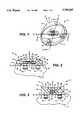
- FIG. 1is a perspective view of an embodiment of an implantable patellar prosthesis for replacing the natural articulation surface of a patella.
- FIG. 2is a cross-sectional view of the prosthesis of FIG. 1, taken along plane 2--2 and viewed in the direction of the arrows.
- FIG. 3is a cross-sectional view of the prosthesis of FIG. 1, taken along plane 3--3 and viewed in the direction of the arrows.
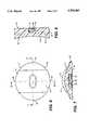
- FIG. 4is a side view of a base component of the prosthesis of FIG. 1.
- FIG. 5is a bottom view of the base component of FIG. 4.
- FIG. 6is a top view of an articulation component of the prosthesis of FIG. 1.
- FIG. 7is a cross-sectional view of the articulation component of FIG. 6 taken along plane 7--7 and viewed in the direction of the arrows.
- FIG. 8is a cross-sectional view of the articulation component of FIG. 6 taken along plane 8--8 and viewed in the direction of the arrows.
- FIGS. 1-3there is illustrated an implantable patellar prosthesis 10 having an articulation component 12 and a base component 14 shown relative to mutually orthogonal reference axes X, Y and Z.
- reference axes X, Y and Zcorrespond, generally, to well known and accepted anatomical directional terms.
- the X axisextends generally in the medial-lateral direction
- the Y axisextends generally in the inferior-superior direction
- the Z axisextends generally in the posterior-anterior direction.
- the ends of each of the X, Y, and Z axes marked with an arrowheadwould point generally in the medial, superior and posterior directions, respectively.
- the patellais resected in a plane generally perpendicular to the anterior-posterior direction to remove a posterior portion of the patellar bone, leaving a resected planar bony surface 15.
- the Z axislies perpendicular to the resected planar bony surface 15 of a patella 13, and the X and Y axes lie parallel to the resected planar bony surface 15.
- Articulation component 12is constructed of a biocompatible material having desirable wear and bearing friction properties, such as ultra-high molecular weight polyethylene. Articulation component 12 includes and is bounded and defined by an articulation surface 16, a planar bearing surface 18 generally perpendicular to the Z axis and spaced from the articulation surface 16, and a perimetrical wall 20 that is generally parallel to the Z axis and that connects the articulation surface 16 and the planar bearing surface 18. In the plane defined by the X and Y axes, perimetrical wall 20 is generally elliptical, with the major axis oriented generally in the medial-lateral direction, along the X axis.
- Articulation surface 16, in the preferred embodiment shown,is a hyperbolic paraboloid, also known as a "saddle" shape, in which the intersection of the surface 16 and perimetrical wall 20 defines an undulating edge 22.
- Points 24 and 26 at opposite ends of the "saddle”designate the locations at which undulating edge 22 is at its maximum spacing from planar bearing surface 18.
- Points 24 and 26are on the minor axis of elliptical perimetric wall 20, and are disposed relative to each other generally in the inferior-superior direction, along the Y axis.
- Points 28 and 30 at opposite sides of the "saddle”designate the locations at which undulating edge 22 is at its minimum spacing from planar bearing surface 18.
- Points 28 and 30are on the major axis of elliptical perimetric wall 20, and are disposed relative to each other generally in the medial-lateral direction, along the X axis.
- Articulation surface 16, so configuredideally provides congruent sliding contact over an extensive range of articulation between articulation component 12 and the patellar articulation surface of a femoral prosthesis component (not shown) at the patellofemoral joint.
- Undulating edge 22 at points 24 and 26 at the high ends of the "saddle"functionally defines a ridge that can track the intercondylar groove of the femoral component during flexion and extension of the knee joint.
- Base component 14is constructed of a biocompatible material having desirable wear, bearing friction, and bone engaging properties. Examples of such a material are titanium, titanium alloys, zirconia ceramics, aluminum oxide ceramics, and cobalt chromium alloys.
- Base component 14includes and is bounded and defined by a fixation surface 32 for engaging patellar bone 15, a planar bearing surface 34 generally perpendicular to the Z axis and spaced from the fixation surface 32, and a perimetrical wall 36 that is generally parallel to the Z axis and that connects the fixation surface 32 and the planar bearing surface 34. In the plane defined by the X and Y axes, perimetrical wall 36 is generally circular.
- Fixation surface 32includes a generally planar surface portion 38 for engaging resected planar bony surface 13 generally parallel thereto, directly or via a mantle of bone cement.
- Planar surface portion 38can include surface texturing to promote osseointegration of fixation component 14.
- Such surface texturingcan be provided by a coating of hydroxyapatite or other ceramics, or porous metal, for example.
- Such coatingscan be applied by plasma spraying of powdered material or, for porous metal coatings, by sintering powdered metal or beads. Suitable metals include titanium and its alloys and cobalt chromium alloys. Other materials and methods for providing a surface that favors osseointegration are well known in the art.
- Fixation surface 32also includes three pins, or pegs, 40, evenly and symmetrically spaced, extending integrally from fixation surface 32 generally in the anterior direction, parallel to the Z axis. Pins 40 are received in correspondingly shaped bores 42 in patella 15. Pins 40 are provided with a waist 44 of a reduced diameter, and alternatively can be straight or provided with other macro-textured surface profiles, to enhance fixation of fixation component 14 to patellar bone 15, either by bone cement or osseointegration.
- Articulation component 12includes an elongate groove 46 that opens to planar bearing surface 18 and oriented longitudinally parallel to a line drawn between points 28 and 30 at the low points of perimetrical wall 20.
- groove 46extends longitudinally generally in the medial-lateral direction, along the X axis.
- Groove 46is of constant and similar width at its base 48 and at its opening 50, but is of reduced width therebetween, presenting a narrowed throat 52 in transverse cross-section.
- Groove 46is arcuate at each end 54 and 56, subtending an angle of about 180 degrees between each side of groove 46.
- Each arcuate end 54 and 56is similar in profile to the sides of groove 46, presenting a like narrowed throat 52 when viewed in cross-section.
- Fixation component 14includes a pin, or peg, 58, centered on and extending integrally from planar bearing surface 34 in the posterior direction, along the Z. axis.
- Pin 58is circular in cross-section, but with a diameter that varies in the profile generally complementarily to the profile of groove 46.
- Articulation component 12 and fixation component 14are configured to engage each other in a snap-retaining relationship, such that the opening of groove 46 deforms elastically under pressure to permit entry of pin 58, and afterwards elastically rebounds to engage and to retain pin 58. When so retained, groove 46 can rotate and translate relative to pin 58. When articulation component 12 and fixation component 14 are so engaged, planar bearing surface 18 of articulation component 12 lies in intimate parallel engagement with planar bearing surface 34 of fixation component 14.
- the width of groove 46, relative to the diameter of pin 58,is such as to preclude substantial movement of articulation component 12 transversely to groove 46 in the plane defined by axes X and Y, whereas articulation component 12 can translate freely in that same plane along the length of groove 46 between the arcuate ends 54 and 56 of groove 46. Because pin 58 is fixed relative to planar bearing surface 34, such movement results in parallel sliding translation of planar bearing surface 18 relative to planar bearing surface 34. It follows that articulation component 12 can rotate about an axis at and defined by pin 58 at any point along the length of groove 46, resulting in rotational sliding of bearing surface 18 relative to bearing surface 34.
- the articulation componentis said to enjoy several degrees of freedom of movement relative to the base component.
- degree of freedomis used in its ordinary engineering sense to mean freedom of a component to rotate about or translate along a line that is parallel to one axis of a three-axis Cartesian coordinate system fixed in orientation relative to the reference component.
- the freedom to rotate about such a linecomprises one degree of rotational freedom
- the freedom to translate along such a linecomprises one translational degree of freedom.
- a componentcan enjoy a maximum of six degrees of freedom, in which case the component can rotate about any axis and can translate along any axis. Essentially, a component with six degrees of freedom is unconstrained by any other component.
- articulation component 12enjoys one, and only one, rotational degree of freedom. Articulation component is constrained from rotating about the X or Y axes by the planar engagement of bearing surface 18 against bearing surface 34. Articulation component 12 may freely rotate about the Z axis, however.
- articulation component 12enjoys only two translational degrees of freedom. Articulation component 12 is constrained against translation in the Z axis by the engagement of bearing surface 18 against bearing surface 34, and by the axially retentive engagement of pin 58 and groove 46. It should be noted that because of the elongate form of groove 46, translation of articulation component 12 in the plane defined by the X and Y axes is limited by the rotational orientation of articulation component 12 relative to fixation component 14. Thus, for any given rotational orientation, only one translational degree of freedom is afforded. Conversely, rotation is not limited by the translational position, because articulation component 12 can rotate about the axis of pin 58 regardless of the translational position of groove 46 relative to pin 58.
- the articulation component 12is free to translate and rotate to its correct and optimum location and orientation relative to the femoral component, despite misplacement of the fixation component relative to the patella, with respect to both rotational orientation and medial-lateral position.
Landscapes
- Health & Medical Sciences (AREA)
- Orthopedic Medicine & Surgery (AREA)
- Physical Education & Sports Medicine (AREA)
- Cardiology (AREA)
- Oral & Maxillofacial Surgery (AREA)
- Transplantation (AREA)
- Engineering & Computer Science (AREA)
- Biomedical Technology (AREA)
- Heart & Thoracic Surgery (AREA)
- Vascular Medicine (AREA)
- Life Sciences & Earth Sciences (AREA)
- Animal Behavior & Ethology (AREA)
- General Health & Medical Sciences (AREA)
- Public Health (AREA)
- Veterinary Medicine (AREA)
- Prostheses (AREA)
Abstract
Description
Claims (10)
Priority Applications (3)
| Application Number | Priority Date | Filing Date | Title |
|---|---|---|---|
| US08/648,222US5702465A (en) | 1996-05-13 | 1996-05-13 | Patella prosthesis having rotational and translational freedom |
| EP97927618AEP0861057A1 (en) | 1996-05-13 | 1997-05-13 | Patella prosthesis having rotational and translational freedom |
| PCT/US1997/007986WO1997042914A1 (en) | 1996-05-13 | 1997-05-13 | Patella prosthesis having rotational and translational freedom |
Applications Claiming Priority (1)
| Application Number | Priority Date | Filing Date | Title |
|---|---|---|---|
| US08/648,222US5702465A (en) | 1996-05-13 | 1996-05-13 | Patella prosthesis having rotational and translational freedom |
Publications (1)
| Publication Number | Publication Date |
|---|---|
| US5702465Atrue US5702465A (en) | 1997-12-30 |
Family
ID=24599905
Family Applications (1)
| Application Number | Title | Priority Date | Filing Date |
|---|---|---|---|
| US08/648,222Expired - LifetimeUS5702465A (en) | 1996-05-13 | 1996-05-13 | Patella prosthesis having rotational and translational freedom |
Country Status (3)
| Country | Link |
|---|---|
| US (1) | US5702465A (en) |
| EP (1) | EP0861057A1 (en) |
| WO (1) | WO1997042914A1 (en) |
Cited By (60)
| Publication number | Priority date | Publication date | Assignee | Title |
|---|---|---|---|---|
| US6146423A (en)* | 1999-01-28 | 2000-11-14 | Implex Corporation | Patella replacement apparatus |
| US6602292B2 (en)* | 2001-03-06 | 2003-08-05 | Centerpulse Orthopedic Inc. | Mobile bearing patella prosthesis |
| US20030225456A1 (en)* | 2000-05-01 | 2003-12-04 | Ek Steven W. | System and method for joint resurface repair |
| US20040143337A1 (en)* | 2003-01-21 | 2004-07-22 | Brian Burkinshaw | Mobile bearing patellar prosthesis with orbital translation |
| US20040143336A1 (en)* | 2003-01-22 | 2004-07-22 | Brian Burkinshaw | Two-piece modular patellar prosthetic system |
| US20040143338A1 (en)* | 2003-01-21 | 2004-07-22 | Brian Burkinshaw | Multi-piece modular patellar prosthetic system |
| US20050008990A1 (en)* | 2003-02-26 | 2005-01-13 | Therics, Inc. | Method and system for repairing endosseous implants, such as with a bone graft implant |
| US6855150B1 (en)* | 2001-07-13 | 2005-02-15 | Timothy R. Linehan | Patellar trial and drill guide for use in knee replacement surgery |
| US20050165492A1 (en)* | 2004-01-23 | 2005-07-28 | Wolfgang Fitz | Bone protector, kit and method |
| EP1582184A1 (en)* | 2004-03-31 | 2005-10-05 | Depuy Products, Inc. | Sliding patellar prosthesis |
| EP1611871A1 (en)* | 2004-07-02 | 2006-01-04 | Zimmer Technology, Inc. | Multiple piece modular patellar prosthetic system |
| US20060229726A1 (en)* | 2000-05-01 | 2006-10-12 | Ek Steven W | Articular surface implant |
| WO2007128991A1 (en)* | 2006-04-07 | 2007-11-15 | Depuy International Limited | Patella tracking |
| US7510558B2 (en) | 2000-05-01 | 2009-03-31 | Arthrosurface, Inc. | System and method for joint resurface repair |
| US20090204217A1 (en)* | 2002-09-18 | 2009-08-13 | Daniel Baumgartner | Implant comprising a two-piece joint |
| US7604641B2 (en) | 2000-05-01 | 2009-10-20 | Arthrosurface Incorporated | System and method for joint resurface repair |
| US7618462B2 (en) | 2000-05-01 | 2009-11-17 | Arthrosurface Incorporated | System and method for joint resurface repair |
| US20100057211A1 (en)* | 2008-09-03 | 2010-03-04 | Biomet Manufacturing Corp. | Revision patella prosthesis |
| US20100131068A1 (en)* | 2006-05-15 | 2010-05-27 | Biomet Manufacturing Corp. | Porous Titanium Modular Revision Patella System |
| US20100185294A1 (en)* | 2002-06-04 | 2010-07-22 | Arthrosurface Incorporated | Nanorough Alloy Substrate |
| US20100198354A1 (en)* | 2007-08-01 | 2010-08-05 | Jeffrey Halbrecht | Method and system for patella tendon realignment |
| US7828853B2 (en) | 2004-11-22 | 2010-11-09 | Arthrosurface, Inc. | Articular surface implant and delivery system |
| US7896885B2 (en) | 2002-12-03 | 2011-03-01 | Arthrosurface Inc. | Retrograde delivery of resurfacing devices |
| US7896883B2 (en) | 2000-05-01 | 2011-03-01 | Arthrosurface, Inc. | Bone resurfacing system and method |
| US7901408B2 (en) | 2002-12-03 | 2011-03-08 | Arthrosurface, Inc. | System and method for retrograde procedure |
| US7914545B2 (en) | 2002-12-03 | 2011-03-29 | Arthrosurface, Inc | System and method for retrograde procedure |
| US7951163B2 (en) | 2003-11-20 | 2011-05-31 | Arthrosurface, Inc. | Retrograde excision system and apparatus |
| US8177841B2 (en) | 2000-05-01 | 2012-05-15 | Arthrosurface Inc. | System and method for joint resurface repair |
| US8361159B2 (en) | 2002-12-03 | 2013-01-29 | Arthrosurface, Inc. | System for articular surface replacement |
| US8388624B2 (en) | 2003-02-24 | 2013-03-05 | Arthrosurface Incorporated | Trochlear resurfacing system and method |
| US8523872B2 (en) | 2002-12-03 | 2013-09-03 | Arthrosurface Incorporated | Tibial resurfacing system |
| US8834574B2 (en) | 2010-12-07 | 2014-09-16 | Zimmer, Inc. | Prosthetic patella |
| US9066716B2 (en) | 2011-03-30 | 2015-06-30 | Arthrosurface Incorporated | Suture coil and suture sheath for tissue repair |
| US9278004B2 (en) | 2009-08-27 | 2016-03-08 | Cotera, Inc. | Method and apparatus for altering biomechanics of the articular joints |
| US9283076B2 (en) | 2009-04-17 | 2016-03-15 | Arthrosurface Incorporated | Glenoid resurfacing system and method |
| US9358029B2 (en) | 2006-12-11 | 2016-06-07 | Arthrosurface Incorporated | Retrograde resection apparatus and method |
| US9468466B1 (en) | 2012-08-24 | 2016-10-18 | Cotera, Inc. | Method and apparatus for altering biomechanics of the spine |
| US9468448B2 (en) | 2012-07-03 | 2016-10-18 | Arthrosurface Incorporated | System and method for joint resurfacing and repair |
| US9492200B2 (en) | 2013-04-16 | 2016-11-15 | Arthrosurface Incorporated | Suture system and method |
| US9662126B2 (en) | 2009-04-17 | 2017-05-30 | Arthrosurface Incorporated | Glenoid resurfacing system and method |
| US9668868B2 (en) | 2009-08-27 | 2017-06-06 | Cotera, Inc. | Apparatus and methods for treatment of patellofemoral conditions |
| US9795410B2 (en) | 2009-08-27 | 2017-10-24 | Cotera, Inc. | Method and apparatus for force redistribution in articular joints |
| US9861492B2 (en) | 2014-03-07 | 2018-01-09 | Arthrosurface Incorporated | Anchor for an implant assembly |
| US9861408B2 (en) | 2009-08-27 | 2018-01-09 | The Foundry, Llc | Method and apparatus for treating canine cruciate ligament disease |
| US10349980B2 (en) | 2009-08-27 | 2019-07-16 | The Foundry, Llc | Method and apparatus for altering biomechanics of the shoulder |
| WO2020028091A1 (en)* | 2018-08-01 | 2020-02-06 | b-ONE Ortho, Corp. | Patellar implant |
| US10624748B2 (en) | 2014-03-07 | 2020-04-21 | Arthrosurface Incorporated | System and method for repairing articular surfaces |
| US10624752B2 (en) | 2006-07-17 | 2020-04-21 | Arthrosurface Incorporated | Tibial resurfacing system and method |
| US10893948B2 (en) | 2017-11-02 | 2021-01-19 | Howmedica Osteonics Corp. | Rotary arc patella articulating geometry |
| US10945743B2 (en) | 2009-04-17 | 2021-03-16 | Arthrosurface Incorporated | Glenoid repair system and methods of use thereof |
| US11160663B2 (en) | 2017-08-04 | 2021-11-02 | Arthrosurface Incorporated | Multicomponent articular surface implant |
| US11357635B2 (en)* | 2019-12-17 | 2022-06-14 | Depuy Ireland Unlimited Company | Metal-backed patella component of an orthopaedic knee prosthesis and associated method of making the same |
| WO2022173072A1 (en)* | 2021-02-10 | 2022-08-18 | 주식회사 도이프 | Artificial trochlear groove prosthesis |
| US11478358B2 (en) | 2019-03-12 | 2022-10-25 | Arthrosurface Incorporated | Humeral and glenoid articular surface implant systems and methods |
| US11607319B2 (en) | 2014-03-07 | 2023-03-21 | Arthrosurface Incorporated | System and method for repairing articular surfaces |
| CN115944435A (en)* | 2023-03-14 | 2023-04-11 | 北京爱康宜诚医疗器材有限公司 | Patella prosthesis |
| US11712276B2 (en) | 2011-12-22 | 2023-08-01 | Arthrosurface Incorporated | System and method for bone fixation |
| US11896476B2 (en) | 2020-01-02 | 2024-02-13 | Zkr Orthopedics, Inc. | Patella tendon realignment implant with changeable shape |
| US12226317B2 (en) | 2019-12-17 | 2025-02-18 | Depuy Ireland Unlimited Company | Metal-backed tibial component of an orthopaedic knee prosthesis and associated method of making the same |
| US12303396B2 (en) | 2020-05-11 | 2025-05-20 | Zkr Orthopedics, Inc. | Adjustable patellar tendon realignment implant |
Families Citing this family (1)
| Publication number | Priority date | Publication date | Assignee | Title |
|---|---|---|---|---|
| EP4197497A1 (en)* | 2021-12-15 | 2023-06-21 | Aesculap AG | Patella trial implant |
Citations (6)
| Publication number | Priority date | Publication date | Assignee | Title |
|---|---|---|---|---|
| US4085466A (en)* | 1974-11-18 | 1978-04-25 | National Research Development Corporation | Prosthetic joint device |
| US4219893A (en)* | 1977-09-01 | 1980-09-02 | United States Surgical Corporation | Prosthetic knee joint |
| US4470158A (en)* | 1978-03-10 | 1984-09-11 | Biomedical Engineering Corp. | Joint endoprosthesis |
| US4950297A (en)* | 1984-12-20 | 1990-08-21 | Chas F Thackray Limited | Knee prosthesis |
| US4979957A (en)* | 1989-09-11 | 1990-12-25 | Zimmer, Inc. | Textured prosthetic implant |
| US5330533A (en)* | 1991-02-04 | 1994-07-19 | Walker Peter S | Prosthesis for knee replacement |
Family Cites Families (2)
| Publication number | Priority date | Publication date | Assignee | Title |
|---|---|---|---|---|
| US5395401A (en)* | 1991-06-17 | 1995-03-07 | Bahler; Andre | Prosthetic device for a complex joint |
| EP0582514A1 (en)* | 1992-08-03 | 1994-02-09 | IMPLANTS ORTHOPEDIQUES TOUTES APPLICATIONS, S.A.R.L. dite: | Knee prosthesis |
- 1996
- 1996-05-13USUS08/648,222patent/US5702465A/ennot_activeExpired - Lifetime
- 1997
- 1997-05-13EPEP97927618Apatent/EP0861057A1/ennot_activeWithdrawn
- 1997-05-13WOPCT/US1997/007986patent/WO1997042914A1/ennot_activeApplication Discontinuation
Patent Citations (6)
| Publication number | Priority date | Publication date | Assignee | Title |
|---|---|---|---|---|
| US4085466A (en)* | 1974-11-18 | 1978-04-25 | National Research Development Corporation | Prosthetic joint device |
| US4219893A (en)* | 1977-09-01 | 1980-09-02 | United States Surgical Corporation | Prosthetic knee joint |
| US4470158A (en)* | 1978-03-10 | 1984-09-11 | Biomedical Engineering Corp. | Joint endoprosthesis |
| US4950297A (en)* | 1984-12-20 | 1990-08-21 | Chas F Thackray Limited | Knee prosthesis |
| US4979957A (en)* | 1989-09-11 | 1990-12-25 | Zimmer, Inc. | Textured prosthetic implant |
| US5330533A (en)* | 1991-02-04 | 1994-07-19 | Walker Peter S | Prosthesis for knee replacement |
Cited By (121)
| Publication number | Priority date | Publication date | Assignee | Title |
|---|---|---|---|---|
| US6146423A (en)* | 1999-01-28 | 2000-11-14 | Implex Corporation | Patella replacement apparatus |
| US8864827B2 (en) | 2000-05-01 | 2014-10-21 | Arthrosurface Inc. | System and method for joint resurface repair |
| US20030225456A1 (en)* | 2000-05-01 | 2003-12-04 | Ek Steven W. | System and method for joint resurface repair |
| US8540717B2 (en) | 2000-05-01 | 2013-09-24 | Arthrosurface Incorporated | System and method for joint resurface repair |
| US8177841B2 (en) | 2000-05-01 | 2012-05-15 | Arthrosurface Inc. | System and method for joint resurface repair |
| US8147559B2 (en) | 2000-05-01 | 2012-04-03 | Arthrosurface Incorporated | System and method for joint resurface repair |
| US9204873B2 (en) | 2000-05-01 | 2015-12-08 | Arthrosurface Incorporated | System and method for joint resurface repair |
| US7896883B2 (en) | 2000-05-01 | 2011-03-01 | Arthrosurface, Inc. | Bone resurfacing system and method |
| US7857817B2 (en) | 2000-05-01 | 2010-12-28 | Arthrosurface Inc. | System and method for joint resurface repair |
| US7510558B2 (en) | 2000-05-01 | 2009-03-31 | Arthrosurface, Inc. | System and method for joint resurface repair |
| US9357989B2 (en) | 2000-05-01 | 2016-06-07 | Arthrosurface Incorporated | System and method for joint resurface repair |
| US9055955B2 (en) | 2000-05-01 | 2015-06-16 | Arthrosurface Inc. | Bone resurfacing system and method |
| US20060229726A1 (en)* | 2000-05-01 | 2006-10-12 | Ek Steven W | Articular surface implant |
| WO2004075777A3 (en)* | 2000-05-01 | 2005-03-10 | Arthrosurface Inc | System and method for joint resurface repair |
| US7713305B2 (en)* | 2000-05-01 | 2010-05-11 | Arthrosurface, Inc. | Articular surface implant |
| US7678151B2 (en)* | 2000-05-01 | 2010-03-16 | Ek Steven W | System and method for joint resurface repair |
| US7618462B2 (en) | 2000-05-01 | 2009-11-17 | Arthrosurface Incorporated | System and method for joint resurface repair |
| US7604641B2 (en) | 2000-05-01 | 2009-10-20 | Arthrosurface Incorporated | System and method for joint resurface repair |
| US6602292B2 (en)* | 2001-03-06 | 2003-08-05 | Centerpulse Orthopedic Inc. | Mobile bearing patella prosthesis |
| US6855150B1 (en)* | 2001-07-13 | 2005-02-15 | Timothy R. Linehan | Patellar trial and drill guide for use in knee replacement surgery |
| US20100185294A1 (en)* | 2002-06-04 | 2010-07-22 | Arthrosurface Incorporated | Nanorough Alloy Substrate |
| US20090204217A1 (en)* | 2002-09-18 | 2009-08-13 | Daniel Baumgartner | Implant comprising a two-piece joint |
| US10076343B2 (en) | 2002-12-03 | 2018-09-18 | Arthrosurface Incorporated | System for articular surface replacement |
| US7896885B2 (en) | 2002-12-03 | 2011-03-01 | Arthrosurface Inc. | Retrograde delivery of resurfacing devices |
| US8523872B2 (en) | 2002-12-03 | 2013-09-03 | Arthrosurface Incorporated | Tibial resurfacing system |
| US8361159B2 (en) | 2002-12-03 | 2013-01-29 | Arthrosurface, Inc. | System for articular surface replacement |
| US8556902B2 (en) | 2002-12-03 | 2013-10-15 | Arthrosurface Incorporated | System and method for retrograde procedure |
| US8663230B2 (en) | 2002-12-03 | 2014-03-04 | Arthrosurface Incorporated | Retrograde delivery of resurfacing devices |
| US7914545B2 (en) | 2002-12-03 | 2011-03-29 | Arthrosurface, Inc | System and method for retrograde procedure |
| US9044343B2 (en) | 2002-12-03 | 2015-06-02 | Arthrosurface Incorporated | System for articular surface replacement |
| US7901408B2 (en) | 2002-12-03 | 2011-03-08 | Arthrosurface, Inc. | System and method for retrograde procedure |
| US8926615B2 (en) | 2002-12-03 | 2015-01-06 | Arthrosurface, Inc. | System and method for retrograde procedure |
| US20040143338A1 (en)* | 2003-01-21 | 2004-07-22 | Brian Burkinshaw | Multi-piece modular patellar prosthetic system |
| US20040143337A1 (en)* | 2003-01-21 | 2004-07-22 | Brian Burkinshaw | Mobile bearing patellar prosthesis with orbital translation |
| US6800094B2 (en) | 2003-01-21 | 2004-10-05 | Zimmer Technology, Inc. | Mobile bearing patellar prosthesis with orbital translation |
| WO2004064674A3 (en)* | 2003-01-21 | 2004-11-25 | Ct Pulse Orthopedics Inc | Mobile bearing patellar prosthesis with orbital translation |
| US20040236428A1 (en)* | 2003-01-21 | 2004-11-25 | Zimmer Technology, Inc. | Multi-piece modular patellar prosthetic system |
| WO2004064674A2 (en) | 2003-01-21 | 2004-08-05 | Centerpulse Orthopedics Inc. | Mobile bearing patellar prosthesis with orbital translation |
| WO2004064675A2 (en) | 2003-01-22 | 2004-08-05 | Centerpulse Orthopedics Inc. | Two-piece modular patellar prosthetic system |
| US20040143336A1 (en)* | 2003-01-22 | 2004-07-22 | Brian Burkinshaw | Two-piece modular patellar prosthetic system |
| US9931211B2 (en) | 2003-02-24 | 2018-04-03 | Arthrosurface Incorporated | Trochlear resurfacing system and method |
| US11337819B2 (en) | 2003-02-24 | 2022-05-24 | Arthrosurface Incorporated | Trochlear resurfacing system and method |
| US10624749B2 (en) | 2003-02-24 | 2020-04-21 | Arthrosurface Incorporated | Trochlear resurfacing system and method |
| US8388624B2 (en) | 2003-02-24 | 2013-03-05 | Arthrosurface Incorporated | Trochlear resurfacing system and method |
| US9351745B2 (en) | 2003-02-24 | 2016-05-31 | Arthrosurface Incorporated | Trochlear resurfacing system and method |
| US20050008990A1 (en)* | 2003-02-26 | 2005-01-13 | Therics, Inc. | Method and system for repairing endosseous implants, such as with a bone graft implant |
| US7951163B2 (en) | 2003-11-20 | 2011-05-31 | Arthrosurface, Inc. | Retrograde excision system and apparatus |
| US7749276B2 (en)* | 2004-01-23 | 2010-07-06 | Depuy Products, Inc. | Bone protector, kit and method |
| US20100125338A1 (en)* | 2004-01-23 | 2010-05-20 | Depuy Products, Inc. | Bone protector, kit and method |
| US8133233B2 (en) | 2004-01-23 | 2012-03-13 | Depuy Products, Inc. | Bone protector, kit and method |
| US20050165492A1 (en)* | 2004-01-23 | 2005-07-28 | Wolfgang Fitz | Bone protector, kit and method |
| US20050222685A1 (en)* | 2004-03-31 | 2005-10-06 | Hayden Adam I | Sliding patellar prosthesis |
| US8506639B2 (en)* | 2004-03-31 | 2013-08-13 | DePuy Synthes Products, LLC | Sliding patellar prosthesis |
| EP1582184A1 (en)* | 2004-03-31 | 2005-10-05 | Depuy Products, Inc. | Sliding patellar prosthesis |
| EP1611871A1 (en)* | 2004-07-02 | 2006-01-04 | Zimmer Technology, Inc. | Multiple piece modular patellar prosthetic system |
| US7828853B2 (en) | 2004-11-22 | 2010-11-09 | Arthrosurface, Inc. | Articular surface implant and delivery system |
| US8961614B2 (en) | 2004-11-22 | 2015-02-24 | Arthrosurface, Inc. | Articular surface implant and delivery system |
| US8361160B2 (en) | 2006-04-07 | 2013-01-29 | Depuy Orthopadie Gmbh | Patella tracking |
| AU2007246925B2 (en)* | 2006-04-07 | 2012-08-02 | Depuy International Limited | Patella tracking |
| US20090264737A1 (en)* | 2006-04-07 | 2009-10-22 | Joerg Haechler | Patella tracking |
| WO2007128991A1 (en)* | 2006-04-07 | 2007-11-15 | Depuy International Limited | Patella tracking |
| US20100131068A1 (en)* | 2006-05-15 | 2010-05-27 | Biomet Manufacturing Corp. | Porous Titanium Modular Revision Patella System |
| US8268005B2 (en)* | 2006-05-15 | 2012-09-18 | Biomet Manufacturing Corp. | Porous titanium modular revision patella system |
| US10624752B2 (en) | 2006-07-17 | 2020-04-21 | Arthrosurface Incorporated | Tibial resurfacing system and method |
| US11471289B2 (en) | 2006-07-17 | 2022-10-18 | Arthrosurface Incorporated | Tibial resurfacing system and method |
| US10045788B2 (en) | 2006-12-11 | 2018-08-14 | Arthrosurface Incorporated | Retrograde resection apparatus and method |
| US9358029B2 (en) | 2006-12-11 | 2016-06-07 | Arthrosurface Incorporated | Retrograde resection apparatus and method |
| US10959740B2 (en) | 2006-12-11 | 2021-03-30 | Arthrosurface Incorporated | Retrograde resection apparatus and method |
| US10918415B2 (en) | 2007-08-01 | 2021-02-16 | Zkr Orthopedics, Inc. | Method and system for patella tendon realignment |
| US10918416B2 (en) | 2007-08-01 | 2021-02-16 | Zkr Orthopedics, Inc. | Method and system for patella tendon realignment |
| US20100198354A1 (en)* | 2007-08-01 | 2010-08-05 | Jeffrey Halbrecht | Method and system for patella tendon realignment |
| US9808287B2 (en) | 2007-08-01 | 2017-11-07 | Jeffrey Halbrecht | Method and system for patella tendon realignment |
| US8696754B2 (en) | 2008-09-03 | 2014-04-15 | Biomet Manufacturing, Llc | Revision patella prosthesis |
| US20100057211A1 (en)* | 2008-09-03 | 2010-03-04 | Biomet Manufacturing Corp. | Revision patella prosthesis |
| US9662126B2 (en) | 2009-04-17 | 2017-05-30 | Arthrosurface Incorporated | Glenoid resurfacing system and method |
| US10945743B2 (en) | 2009-04-17 | 2021-03-16 | Arthrosurface Incorporated | Glenoid repair system and methods of use thereof |
| US10478200B2 (en) | 2009-04-17 | 2019-11-19 | Arthrosurface Incorporated | Glenoid resurfacing system and method |
| US9283076B2 (en) | 2009-04-17 | 2016-03-15 | Arthrosurface Incorporated | Glenoid resurfacing system and method |
| US11478259B2 (en) | 2009-04-17 | 2022-10-25 | Arthrosurface, Incorporated | Glenoid resurfacing system and method |
| US10349980B2 (en) | 2009-08-27 | 2019-07-16 | The Foundry, Llc | Method and apparatus for altering biomechanics of the shoulder |
| US9795410B2 (en) | 2009-08-27 | 2017-10-24 | Cotera, Inc. | Method and apparatus for force redistribution in articular joints |
| US11730519B2 (en) | 2009-08-27 | 2023-08-22 | The Foundry, Llc | Method and apparatus for force redistribution in articular joints |
| US11517360B2 (en) | 2009-08-27 | 2022-12-06 | The Foundry, Llc | Method and apparatus for treating canine cruciate ligament disease |
| US9931136B2 (en) | 2009-08-27 | 2018-04-03 | The Foundry, Llc | Method and apparatus for altering biomechanics of articular joints |
| US9861408B2 (en) | 2009-08-27 | 2018-01-09 | The Foundry, Llc | Method and apparatus for treating canine cruciate ligament disease |
| US9278004B2 (en) | 2009-08-27 | 2016-03-08 | Cotera, Inc. | Method and apparatus for altering biomechanics of the articular joints |
| US9668868B2 (en) | 2009-08-27 | 2017-06-06 | Cotera, Inc. | Apparatus and methods for treatment of patellofemoral conditions |
| US10695094B2 (en) | 2009-08-27 | 2020-06-30 | The Foundry, Llc | Method and apparatus for altering biomechanics of articular joints |
| US8834574B2 (en) | 2010-12-07 | 2014-09-16 | Zimmer, Inc. | Prosthetic patella |
| US9066716B2 (en) | 2011-03-30 | 2015-06-30 | Arthrosurface Incorporated | Suture coil and suture sheath for tissue repair |
| US11712276B2 (en) | 2011-12-22 | 2023-08-01 | Arthrosurface Incorporated | System and method for bone fixation |
| US9468448B2 (en) | 2012-07-03 | 2016-10-18 | Arthrosurface Incorporated | System and method for joint resurfacing and repair |
| US10307172B2 (en) | 2012-07-03 | 2019-06-04 | Arthrosurface Incorporated | System and method for joint resurfacing and repair |
| US11191552B2 (en) | 2012-07-03 | 2021-12-07 | Arthrosurface, Incorporated | System and method for joint resurfacing and repair |
| US10898237B2 (en) | 2012-08-24 | 2021-01-26 | The Foundry, Llc | Method and apparatus for altering biomechanics of the spine |
| US9468466B1 (en) | 2012-08-24 | 2016-10-18 | Cotera, Inc. | Method and apparatus for altering biomechanics of the spine |
| US11648036B2 (en) | 2013-04-16 | 2023-05-16 | Arthrosurface Incorporated | Suture system and method |
| US10695096B2 (en) | 2013-04-16 | 2020-06-30 | Arthrosurface Incorporated | Suture system and method |
| US9492200B2 (en) | 2013-04-16 | 2016-11-15 | Arthrosurface Incorporated | Suture system and method |
| US9931219B2 (en) | 2014-03-07 | 2018-04-03 | Arthrosurface Incorporated | Implant and anchor assembly |
| US10575957B2 (en) | 2014-03-07 | 2020-03-03 | Arthrosurface Incoporated | Anchor for an implant assembly |
| US11083587B2 (en) | 2014-03-07 | 2021-08-10 | Arthrosurface Incorporated | Implant and anchor assembly |
| US9861492B2 (en) | 2014-03-07 | 2018-01-09 | Arthrosurface Incorporated | Anchor for an implant assembly |
| US11766334B2 (en) | 2014-03-07 | 2023-09-26 | Arthrosurface Incorporated | System and method for repairing articular surfaces |
| US10624748B2 (en) | 2014-03-07 | 2020-04-21 | Arthrosurface Incorporated | System and method for repairing articular surfaces |
| US10624754B2 (en) | 2014-03-07 | 2020-04-21 | Arthrosurface Incorporated | System and method for repairing articular surfaces |
| US11607319B2 (en) | 2014-03-07 | 2023-03-21 | Arthrosurface Incorporated | System and method for repairing articular surfaces |
| US9962265B2 (en) | 2014-03-07 | 2018-05-08 | Arthrosurface Incorporated | System and method for repairing articular surfaces |
| US11241256B2 (en) | 2015-10-15 | 2022-02-08 | The Foundry, Llc | Method and apparatus for altering biomechanics of the shoulder |
| US11160663B2 (en) | 2017-08-04 | 2021-11-02 | Arthrosurface Incorporated | Multicomponent articular surface implant |
| US10893948B2 (en) | 2017-11-02 | 2021-01-19 | Howmedica Osteonics Corp. | Rotary arc patella articulating geometry |
| WO2020028091A1 (en)* | 2018-08-01 | 2020-02-06 | b-ONE Ortho, Corp. | Patellar implant |
| CN112135584A (en)* | 2018-08-01 | 2020-12-25 | 宽岳骨科公司 | patella implant |
| US10842637B2 (en) | 2018-08-01 | 2020-11-24 | b-ONE Ortho, Corp. | Patellar implant |
| US11478358B2 (en) | 2019-03-12 | 2022-10-25 | Arthrosurface Incorporated | Humeral and glenoid articular surface implant systems and methods |
| US11357635B2 (en)* | 2019-12-17 | 2022-06-14 | Depuy Ireland Unlimited Company | Metal-backed patella component of an orthopaedic knee prosthesis and associated method of making the same |
| US12226317B2 (en) | 2019-12-17 | 2025-02-18 | Depuy Ireland Unlimited Company | Metal-backed tibial component of an orthopaedic knee prosthesis and associated method of making the same |
| US11896476B2 (en) | 2020-01-02 | 2024-02-13 | Zkr Orthopedics, Inc. | Patella tendon realignment implant with changeable shape |
| US12303396B2 (en) | 2020-05-11 | 2025-05-20 | Zkr Orthopedics, Inc. | Adjustable patellar tendon realignment implant |
| WO2022173072A1 (en)* | 2021-02-10 | 2022-08-18 | 주식회사 도이프 | Artificial trochlear groove prosthesis |
| CN115944435A (en)* | 2023-03-14 | 2023-04-11 | 北京爱康宜诚医疗器材有限公司 | Patella prosthesis |
Also Published As
| Publication number | Publication date |
|---|---|
| EP0861057A1 (en) | 1998-09-02 |
| WO1997042914A1 (en) | 1997-11-20 |
Similar Documents
| Publication | Publication Date | Title |
|---|---|---|
| US5702465A (en) | Patella prosthesis having rotational and translational freedom | |
| US6800094B2 (en) | Mobile bearing patellar prosthesis with orbital translation | |
| US6602292B2 (en) | Mobile bearing patella prosthesis | |
| US7578850B2 (en) | Unicondylar knee implant | |
| AU2022211895B2 (en) | Tibial tray with fixation features | |
| US12115080B2 (en) | Total knee implant prosthesis assembly and method | |
| US7387644B2 (en) | Knee joint prosthesis with a femoral component which links the tibiofemoral axis of rotation with the patellofemoral axis of rotation | |
| US6770099B2 (en) | Femoral prosthesis | |
| EP0498586B1 (en) | Prosthesis for knee replacement | |
| US5326361A (en) | Total knee endoprosthesis with fixed flexion-extension axis of rotation | |
| US20040143336A1 (en) | Two-piece modular patellar prosthetic system | |
| EP1433444A1 (en) | Mobile talar component for total ankle replacement implant | |
| US10568742B2 (en) | Tibial insert | |
| US20130035765A1 (en) | Total knee arthroplasty with symmetric femoral implant having double q-angle trochlear groove | |
| WO2023081493A1 (en) | Knee arthroplasty system for balance in full range of flexion | |
| EP3821853B1 (en) | Concentric keel total knee arthroplasty |
Legal Events
| Date | Code | Title | Description |
|---|---|---|---|
| AS | Assignment | Owner name:INTERMEDICS ORTHOPEDICS, INC., TEXAS Free format text:ASSIGNMENT OF ASSIGNORS INTEREST;ASSIGNOR:BURKINSHAW, BRIAN D.;REEL/FRAME:008079/0847 Effective date:19960517 | |
| AS | Assignment | Owner name:SULZER ORTHOPEDICS INC., TEXAS Free format text:CHANGE OF NAME;ASSIGNOR:INTERMEDICS ORTHOPEDICS, INC.;REEL/FRAME:008361/0225 Effective date:19961204 | |
| STCF | Information on status: patent grant | Free format text:PATENTED CASE | |
| FEPP | Fee payment procedure | Free format text:PAYOR NUMBER ASSIGNED (ORIGINAL EVENT CODE: ASPN); ENTITY STATUS OF PATENT OWNER: LARGE ENTITY | |
| FPAY | Fee payment | Year of fee payment:4 | |
| AS | Assignment | Owner name:UBS AG, STAMFORD BRANCH AS SECURITY AGENT FOR THE Free format text:SECURITY INTEREST;ASSIGNORS:CENTERPULSE ORTHOPEDICS INC.;CENTERPULSE USA HOLDING CO., CORPORATION, DELAWARE;CENTERPULSE USA INC., CORPORATION, DELAWARE;AND OTHERS;REEL/FRAME:013467/0328 Effective date:20021029 | |
| AS | Assignment | Owner name:CENTERPULSE ORTHOPEDICS INC., TEXAS Free format text:CHANGE OF NAME;ASSIGNOR:SULZER ORTHOPEDICS INC.;REEL/FRAME:013516/0549 Effective date:20020930 | |
| AS | Assignment | Owner name:CENTERPULSE USA INC., TEXAS Free format text:PATENT RELEASE AGREEMENT;ASSIGNOR:UBS AG, STAMFORD BRANCH;REEL/FRAME:014699/0404 Effective date:20031002 | |
| AS | Assignment | Owner name:ZIMMER AUSTIN, INC., TEXAS Free format text:CHANGE OF NAME;ASSIGNOR:CENTERPULSE ORTHOPEDICS INC.;REEL/FRAME:016263/0264 Effective date:20040602 | |
| FPAY | Fee payment | Year of fee payment:8 | |
| AS | Assignment | Owner name:CENTERPULSE ORTHOPEDICS INC., TEXAS Free format text:CHANGE OF NAME;ASSIGNOR:SULZER ORTHOPEDICS INC.;REEL/FRAME:016761/0136 Effective date:20020930 | |
| AS | Assignment | Owner name:ZIMMER, INC., INDIANA Free format text:CHANGE OF NAME;ASSIGNOR:ZIMMER AUSTIN, INC.;REEL/FRAME:017435/0714 Effective date:20060208 | |
| FPAY | Fee payment | Year of fee payment:12 | |
| REMI | Maintenance fee reminder mailed |