US5702441A - Method for rapid implantation of shape transformable optical lenses - Google Patents
Method for rapid implantation of shape transformable optical lensesDownload PDFInfo
- Publication number
- US5702441A US5702441AUS08/607,417US60741796AUS5702441AUS 5702441 AUS5702441 AUS 5702441AUS 60741796 AUS60741796 AUS 60741796AUS 5702441 AUS5702441 AUS 5702441A
- Authority
- US
- United States
- Prior art keywords
- optical lens
- elongate
- generally tubular
- tubular outlet
- lens
- Prior art date
- Legal status (The legal status is an assumption and is not a legal conclusion. Google has not performed a legal analysis and makes no representation as to the accuracy of the status listed.)
- Expired - Lifetime
Links
- 230000003287optical effectEffects0.000titleclaimsabstractdescription74
- 238000000034methodMethods0.000titleclaimsdescription69
- 238000002513implantationMethods0.000titledescription53
- 238000007789sealingMethods0.000claimsdescription7
- 239000012780transparent materialSubstances0.000claimsdescription4
- 238000011144upstream manufacturingMethods0.000claimsdescription4
- 239000003190viscoelastic substanceSubstances0.000claimsdescription4
- 239000011248coating agentSubstances0.000claimsdescription3
- 238000000576coating methodMethods0.000claimsdescription3
- 238000004891communicationMethods0.000claimsdescription3
- 230000001050lubricating effectEffects0.000claimsdescription3
- 239000007943implantSubstances0.000abstractdescription170
- 239000000463materialSubstances0.000abstractdescription49
- 238000006073displacement reactionMethods0.000abstract1
- 230000006870functionEffects0.000description20
- 229920001296polysiloxanePolymers0.000description15
- 239000000499gelSubstances0.000description14
- 229920001971elastomerPolymers0.000description11
- 239000000806elastomerSubstances0.000description10
- 239000000017hydrogelSubstances0.000description10
- 208000002847Surgical WoundDiseases0.000description9
- 238000004519manufacturing processMethods0.000description8
- 238000001356surgical procedureMethods0.000description8
- 238000003780insertionMethods0.000description7
- 230000037431insertionEffects0.000description7
- -1oligomersSubstances0.000description6
- 229920000642polymerPolymers0.000description6
- 210000002159anterior chamberAnatomy0.000description5
- 230000008901benefitEffects0.000description5
- 239000002775capsuleSubstances0.000description5
- 239000007788liquidSubstances0.000description5
- 230000005499meniscusEffects0.000description5
- 239000004215Carbon black (E152)Substances0.000description4
- 210000004087corneaAnatomy0.000description4
- 229930195733hydrocarbonNatural products0.000description4
- 150000002430hydrocarbonsChemical class0.000description4
- 239000000203mixtureSubstances0.000description4
- 239000004014plasticizerSubstances0.000description4
- 239000007787solidSubstances0.000description4
- 238000011161developmentMethods0.000description3
- 239000000314lubricantSubstances0.000description3
- 230000014759maintenance of locationEffects0.000description3
- 230000013011matingEffects0.000description3
- 238000012986modificationMethods0.000description3
- 230000004048modificationEffects0.000description3
- 239000003921oilSubstances0.000description3
- 230000001179pupillary effectEffects0.000description3
- XLYOFNOQVPJJNP-UHFFFAOYSA-NwaterSubstancesOXLYOFNOQVPJJNP-UHFFFAOYSA-N0.000description3
- 239000002033PVDF binderSubstances0.000description2
- 239000004952PolyamideSubstances0.000description2
- 229920002385Sodium hyaluronatePolymers0.000description2
- 230000003416augmentationEffects0.000description2
- 230000009286beneficial effectEffects0.000description2
- 238000005266castingMethods0.000description2
- 229920001577copolymerPolymers0.000description2
- 239000002537cosmeticSubstances0.000description2
- 238000004132cross linkingMethods0.000description2
- 238000005520cutting processMethods0.000description2
- 230000035876healingEffects0.000description2
- 230000036571hydrationEffects0.000description2
- 238000006703hydration reactionMethods0.000description2
- 208000014674injuryDiseases0.000description2
- 230000015654memoryEffects0.000description2
- 229920002647polyamidePolymers0.000description2
- 239000004810polytetrafluoroethyleneSubstances0.000description2
- 229920001343polytetrafluoroethylenePolymers0.000description2
- 229920000915polyvinyl chloridePolymers0.000description2
- 239000004800polyvinyl chlorideSubstances0.000description2
- 229920002981polyvinylidene fluoridePolymers0.000description2
- 108090000765processed proteins & peptidesProteins0.000description2
- 229940010747sodium hyaluronateDrugs0.000description2
- YWIVKILSMZOHHF-QJZPQSOGSA-Nsodium;(2s,3s,4s,5r,6r)-6-[(2s,3r,4r,5s,6r)-3-acetamido-2-[(2s,3s,4r,5r,6r)-6-[(2r,3r,4r,5s,6r)-3-acetamido-2,5-dihydroxy-6-(hydroxymethyl)oxan-4-yl]oxy-2-carboxy-4,5-dihydroxyoxan-3-yl]oxy-5-hydroxy-6-(hydroxymethyl)oxan-4-yl]oxy-3,4,5-trihydroxyoxane-2-Chemical compound[Na+].CC(=O)N[C@H]1[C@H](O)O[C@H](CO)[C@@H](O)[C@@H]1O[C@H]1[C@H](O)[C@@H](O)[C@H](O[C@H]2[C@@H]([C@@H](O[C@H]3[C@@H]([C@@H](O)[C@H](O)[C@H](O3)C(O)=O)O)[C@H](O)[C@@H](CO)O2)NC(C)=O)[C@@H](C(O)=O)O1YWIVKILSMZOHHF-QJZPQSOGSA-N0.000description2
- 210000001519tissueAnatomy0.000description2
- 238000012546transferMethods0.000description2
- 230000008733traumaEffects0.000description2
- 102000008186CollagenHuman genes0.000description1
- 108010035532CollagenProteins0.000description1
- WOBHKFSMXKNTIM-UHFFFAOYSA-NHydroxyethyl methacrylateChemical compoundCC(=C)C(=O)OCCOWOBHKFSMXKNTIM-UHFFFAOYSA-N0.000description1
- WHNWPMSKXPGLAX-UHFFFAOYSA-NN-Vinyl-2-pyrrolidoneChemical compoundC=CN1CCCC1=OWHNWPMSKXPGLAX-UHFFFAOYSA-N0.000description1
- 239000005062PolybutadieneSubstances0.000description1
- 239000004698PolyethyleneSubstances0.000description1
- 239000004743PolypropyleneSubstances0.000description1
- 239000004793PolystyreneSubstances0.000description1
- DBMJMQXJHONAFJ-UHFFFAOYSA-MSodium laurylsulphateChemical compound[Na+].CCCCCCCCCCCCOS([O-])(=O)=ODBMJMQXJHONAFJ-UHFFFAOYSA-M0.000description1
- 230000004308accommodationEffects0.000description1
- 230000006978adaptationEffects0.000description1
- 230000004075alterationEffects0.000description1
- 239000007864aqueous solutionSubstances0.000description1
- 201000009310astigmatismDiseases0.000description1
- 230000015572biosynthetic processEffects0.000description1
- 210000000481breastAnatomy0.000description1
- 230000008859changeEffects0.000description1
- 229920001436collagenPolymers0.000description1
- 244000221110common milletSpecies0.000description1
- 230000000052comparative effectEffects0.000description1
- 150000001875compoundsChemical class0.000description1
- 238000000748compression mouldingMethods0.000description1
- 238000010276constructionMethods0.000description1
- 238000007796conventional methodMethods0.000description1
- 210000005069earsAnatomy0.000description1
- 239000013536elastomeric materialSubstances0.000description1
- 238000005516engineering processMethods0.000description1
- 238000005530etchingMethods0.000description1
- 238000001125extrusionMethods0.000description1
- 239000012530fluidSubstances0.000description1
- 210000003709heart valveAnatomy0.000description1
- 150000004677hydratesChemical class0.000description1
- 229920001477hydrophilic polymerPolymers0.000description1
- 230000001939inductive effectEffects0.000description1
- 238000001746injection mouldingMethods0.000description1
- 230000002045lasting effectEffects0.000description1
- 239000012528membraneSubstances0.000description1
- 238000002406microsurgeryMethods0.000description1
- 230000005012migrationEffects0.000description1
- 238000013508migrationMethods0.000description1
- 238000000465mouldingMethods0.000description1
- BSCJIBOZTKGXQP-UHFFFAOYSA-Nn-(2-hydroxyethyl)-2-methylprop-2-enamideChemical compoundCC(=C)C(=O)NCCOBSCJIBOZTKGXQP-UHFFFAOYSA-N0.000description1
- 210000001331noseAnatomy0.000description1
- 230000037361pathwayEffects0.000description1
- 230000002093peripheral effectEffects0.000description1
- 229920003229poly(methyl methacrylate)Polymers0.000description1
- 229920002857polybutadienePolymers0.000description1
- 229920001748polybutylenePolymers0.000description1
- 229920000573polyethylenePolymers0.000description1
- 229920001195polyisoprenePolymers0.000description1
- 239000004926polymethyl methacrylateSubstances0.000description1
- 229920001155polypropylenePolymers0.000description1
- 229920002223polystyrenePolymers0.000description1
- 230000002980postoperative effectEffects0.000description1
- 230000008569processEffects0.000description1
- 102000004196processed proteins & peptidesHuman genes0.000description1
- 238000011084recoveryMethods0.000description1
- 230000009467reductionEffects0.000description1
- 238000009877renderingMethods0.000description1
- 238000005096rolling processMethods0.000description1
- 239000005060rubberSubstances0.000description1
- 239000000523sampleSubstances0.000description1
- 229920002379silicone rubberPolymers0.000description1
- 235000019333sodium laurylsulphateNutrition0.000description1
- 238000001228spectrumMethods0.000description1
- 239000010935stainless steelSubstances0.000description1
- 229910001220stainless steelInorganic materials0.000description1
- 210000001585trabecular meshworkAnatomy0.000description1
- 238000001721transfer mouldingMethods0.000description1
- 230000009466transformationEffects0.000description1
- 230000000472traumatic effectEffects0.000description1
- 229920000428triblock copolymerPolymers0.000description1
- 230000037303wrinklesEffects0.000description1
- 210000000216zygomaAnatomy0.000description1
Images


Classifications
- A—HUMAN NECESSITIES
- A61—MEDICAL OR VETERINARY SCIENCE; HYGIENE
- A61F—FILTERS IMPLANTABLE INTO BLOOD VESSELS; PROSTHESES; DEVICES PROVIDING PATENCY TO, OR PREVENTING COLLAPSING OF, TUBULAR STRUCTURES OF THE BODY, e.g. STENTS; ORTHOPAEDIC, NURSING OR CONTRACEPTIVE DEVICES; FOMENTATION; TREATMENT OR PROTECTION OF EYES OR EARS; BANDAGES, DRESSINGS OR ABSORBENT PADS; FIRST-AID KITS
- A61F2/00—Filters implantable into blood vessels; Prostheses, i.e. artificial substitutes or replacements for parts of the body; Appliances for connecting them with the body; Devices providing patency to, or preventing collapsing of, tubular structures of the body, e.g. stents
- A61F2/02—Prostheses implantable into the body
- A61F2/14—Eye parts, e.g. lenses or corneal implants; Artificial eyes
- A61F2/16—Intraocular lenses
- A61F2/1662—Instruments for inserting intraocular lenses into the eye
- A61F2/167—Instruments for inserting intraocular lenses into the eye with pushable plungers
- A—HUMAN NECESSITIES
- A61—MEDICAL OR VETERINARY SCIENCE; HYGIENE
- A61F—FILTERS IMPLANTABLE INTO BLOOD VESSELS; PROSTHESES; DEVICES PROVIDING PATENCY TO, OR PREVENTING COLLAPSING OF, TUBULAR STRUCTURES OF THE BODY, e.g. STENTS; ORTHOPAEDIC, NURSING OR CONTRACEPTIVE DEVICES; FOMENTATION; TREATMENT OR PROTECTION OF EYES OR EARS; BANDAGES, DRESSINGS OR ABSORBENT PADS; FIRST-AID KITS
- A61F2/00—Filters implantable into blood vessels; Prostheses, i.e. artificial substitutes or replacements for parts of the body; Appliances for connecting them with the body; Devices providing patency to, or preventing collapsing of, tubular structures of the body, e.g. stents
- A61F2/02—Prostheses implantable into the body
- A61F2/14—Eye parts, e.g. lenses or corneal implants; Artificial eyes
- A61F2/16—Intraocular lenses
- A61F2/1613—Intraocular lenses having special lens configurations, e.g. multipart lenses; having particular optical properties, e.g. pseudo-accommodative lenses, lenses having aberration corrections, diffractive lenses, lenses for variably absorbing electromagnetic radiation, lenses having variable focus
- A61F2/1616—Pseudo-accommodative, e.g. multifocal or enabling monovision
- A—HUMAN NECESSITIES
- A61—MEDICAL OR VETERINARY SCIENCE; HYGIENE
- A61F—FILTERS IMPLANTABLE INTO BLOOD VESSELS; PROSTHESES; DEVICES PROVIDING PATENCY TO, OR PREVENTING COLLAPSING OF, TUBULAR STRUCTURES OF THE BODY, e.g. STENTS; ORTHOPAEDIC, NURSING OR CONTRACEPTIVE DEVICES; FOMENTATION; TREATMENT OR PROTECTION OF EYES OR EARS; BANDAGES, DRESSINGS OR ABSORBENT PADS; FIRST-AID KITS
- A61F2/00—Filters implantable into blood vessels; Prostheses, i.e. artificial substitutes or replacements for parts of the body; Appliances for connecting them with the body; Devices providing patency to, or preventing collapsing of, tubular structures of the body, e.g. stents
- A61F2/02—Prostheses implantable into the body
- A61F2/14—Eye parts, e.g. lenses or corneal implants; Artificial eyes
- A61F2/16—Intraocular lenses
- A61F2/1662—Instruments for inserting intraocular lenses into the eye
- A61F2/1664—Instruments for inserting intraocular lenses into the eye for manual insertion during surgery, e.g. forceps-like instruments
- A—HUMAN NECESSITIES
- A61—MEDICAL OR VETERINARY SCIENCE; HYGIENE
- A61F—FILTERS IMPLANTABLE INTO BLOOD VESSELS; PROSTHESES; DEVICES PROVIDING PATENCY TO, OR PREVENTING COLLAPSING OF, TUBULAR STRUCTURES OF THE BODY, e.g. STENTS; ORTHOPAEDIC, NURSING OR CONTRACEPTIVE DEVICES; FOMENTATION; TREATMENT OR PROTECTION OF EYES OR EARS; BANDAGES, DRESSINGS OR ABSORBENT PADS; FIRST-AID KITS
- A61F2/00—Filters implantable into blood vessels; Prostheses, i.e. artificial substitutes or replacements for parts of the body; Appliances for connecting them with the body; Devices providing patency to, or preventing collapsing of, tubular structures of the body, e.g. stents
- A61F2/02—Prostheses implantable into the body
- A61F2/14—Eye parts, e.g. lenses or corneal implants; Artificial eyes
- A61F2/16—Intraocular lenses
- A61F2/1613—Intraocular lenses having special lens configurations, e.g. multipart lenses; having particular optical properties, e.g. pseudo-accommodative lenses, lenses having aberration corrections, diffractive lenses, lenses for variably absorbing electromagnetic radiation, lenses having variable focus
- A61F2/1648—Multipart lenses
Definitions
- the present inventiongenerally relates to methods and associated apparatus for the insertion and placement of medical implants, particularly intraocular lenses. More particularly, the present invention is directed to methods for the surgical implantation of rapidly shape transformable implants, through an ejector apparatus having a very small diameter, elongate, tubular outlet suitable for very small incision implantation techniques.
- the elastomeric or gelatinous, highly extensible implantspossess lasting memories enabling them to recover their original conformational shapes immediately upon passage through the ejection apparatus allowing for their rapid implantation and positioning.
- the replacement or augmentation of natural body parts with medical implantsis a mature technology having a wide variety of well-developed applications and techniques.
- Many surgically implanted medical devicesperform useful and often essential functions based upon a variety of mechanical properties, including strength and flexibility.
- Common examples of such widely known medical implantsinclude replacement heart valves and artificial joints.
- another class of medical implantsperforms useful and desirable functions by virtue of the physical shape of the implant rather than its structural or mechanical properties.
- Representative examples of this class of medical implantsinclude cosmetic devices designed to augment or replace missing tissue or, more importantly, artificial optical lenses designed to replace or augment the natural lens of the eye. With respect to optical implants, it is the shape of the lens itself that, in conjunction with the refractive index of the lens material, provides the useful light-focussing function. Other minor structural features may be present to assist in the placement or retention of these devices following implantation.
- Recent trends in implantation surgeryhave been directed toward the reduction of patient trauma, discomfort, healing time, and the associated complications that may occur through the utilization of reduced size or small incision surgical implantation techniques.
- the relatively rapid development of arthroscopic and microsurgery techniques and instrumentshas greatly facilitated the ability of the implanting surgeon to confine the physical impact of the surgical procedure to the desired target location which is accessed through a small, often remote incision. In this manner, the implanting surgeon is able to avoid trauma and damage to intervening tissues that would normally be cut and moved aside to provide surgical access using conventional large incision surgical techniques.
- the development of small incision techniqueshas not been particularly successful in conjunction with the implantation of medical devices.
- the principal impediments to the development of small incision techniques for use in conjunction with medical implantsare the volume, the size and rigidity of the implants themselves.
- the typical intraocular lens implantincludes an optical lens portion having a minimum diameter on the order of 6 mm.
- Current trends in the posterior chamber implantation of intraocular lensutilize what are known as "full-sized" optics having lens diameters of 9 mm or more.
- the intraocular lens implantation proceduremust utilize a surgical incision at least as large as the minimum dimension of the optical implant.
- Balloon lenseshave their own problems in that it is difficult to inflate the balloon with any degree of accuracy or control following implantation. Thus, the actual refractive characteristics of the lens is difficult to control. Moreover, complete removal of air bubbles from the balloon remains a significant problem. Similarly, injectable lenses cannot produce predictable optical power and resolution because the natural capsular bag will not consistently produce the necessary or desired lens shape.
- one of the primary objects of the present inventionis to provide a method for the rapid implantation of an optical lens into an eye through a minimally traumatic surgical procedure.
- the shape transformable medical implantsare formed of elastomeric or gelatinous materials capable of substantial recoverable deformation in all dimensions. It was unexpectedly discovered by the present inventor that medical implants formed of these materials can be drawn into and ejected through very small diameter, elongate, generally tubular ejectors which require only very small surgical openings to provide access to the target site within the patient's body. Following implantation, the implants immediately reassume their pre-implant shapes and contours, allowing the implanting surgeon to immediately confirm proper placement and completion of the implantation procedure.
- the implants of the present inventionare capable of recoverable deformation in all dimensions.
- the three-dimensional shapecan be significantly altered into a very small diameter elongate form that, surprisingly, will readily and easily pass through a very small bore implantation ejector with minimal effort.
- the method of the present inventionsimply involves loading the shape transformable implant into an ejector having a small diameter, elongate, generally tubular outlet, inserting and positioning the outlet into a target site within the patient's body and ejecting the implant through the elongate tubular outlet into the target site.
- the diameter of the elongate tubular outletis sufficiently small to enable the outlet to function as a puncturing cannula analogous to a hypodermic needle capable of forming its own access pathway.
- a small surgical incisioncan be made utilizing conventional surgical techniques and the tubular outlet can be inserted therethrough.
- the medical implantmay be loaded into the ejector apparatus of the present invention by either aspirating or drawing the implant into the tubular outlet, or by positioning the implant within the ejector upstream of the tubular outlet and then forcing the implant through.
- the implantpreferably is passed through the ejector outlet during the implantation procedure by pressurizing the ejector in a controlled manner. Precise pressure control enables the implanting surgeon to avoid inadvertent pressurization of the target site.
- the internal recovery properties of the gelatinous materialactually assist in pulling the implant through the ejector into the target site. As a result, only minimal pressure is required to eject the implant during the implantation procedure.
- the shape transformable medical implants of the present inventionmay be placed within a detachable elongate tubular outlet having sufficient internal volume to retain the entire medical implant in its substantially distorted state.
- the implantcan be conveniently sterilized, stored, or transported within the detachable tubular outlet.
- the implant-containing tubular outletsimply is attached to the pressurizable ejector prior to insertion and implantation.
- the present inventionis particularly well-suited for the implantation of optical lenses into the eye for corrective lens replacement (pseudophakic) purposes.
- the optical lensescan be formed from a wide variety of physiologically acceptable materials having an elongation at break of greater than 400% and an elastic modulus of less than 3,000 MPa.
- Exemplary materials for forming the medical implants of the present inventioninclude hydrogels, silicone gels and elastomers, hydrocarbon gels and elastomers, peptide gels, and collagenous gels. When utilized as optical lenses, these gelatinous materials should be formulated to be optically transparent with a suitable final refractive index for light-focussing purposes.
- the optical lens implantsmay be configured as full-sized lenses, having diameters on the order of 8-13 mm or as conventionally-sized 5-7 mm optics which may include one or more radially extending haptic support structures.
- the cross-sectional shape of the optic lensmay be any shape including plano-convex, biconvex, converging meniscus, diverging meniscus, plano-concave, and biconcave.
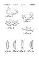
- FIG. 1is a three-dimensional perspective view of an exemplary shape transformable implant illustrating the principles of the present invention and configured to function as an intraocular lens or ejectable lens implant;
- FIG. 2is a three-dimensional perspective view of an exemplary shape transformable implant analogous to that of FIG. 1 and provided with an alternative configuration;
- FIG. 3is a three-dimensional perspective view of an exemplary shape transformable implant analogous to that of FIG. 1 and provided with an additional alternative configuration;
- FIG. 4is a three-dimensional perspective view of an exemplary shape transformable implant analogous to that of FIG. 1 and provided with an alternative multipiece configuration;
- FIG. 5ais a cross-sectional view of an exemplary shape transformable intraocular lens implant having a biconvex configuration
- FIG. 5bis a cross-sectional view of an exemplary shape transformable intraocular lens implant having a plano-convex configuration
- FIG. 5cis a cross-sectional view of an exemplary shape transformable intraocular lens implant having a plano-concave configuration
- FIG. 5dis a cross-sectional view of an exemplary shape transformable intraocular lens implant having a concavo-convex or meniscus configuration
- FIG. 6is a fragmentary cross-sectional view of an exemplary multipiece ejector apparatus of the present invention shown provided with a removable loading funnel prior to implant loading;
- FIG. 7is a fragmentary cross-sectional view of the exemplary multipiece ejector apparatus of FIG. 6 illustrating the loading of a shape transformable implant
- FIG. 8is a fragmentary cross-sectional view of the exemplary multipiece ejector apparatus of FIG. 6 following loading of the shape transformable implant and further illustrating an exemplary detachable implant containing tubular outlet;
- FIG. 9is a fragmentary cross-sectional view of an alternative exemplary ejector apparatus of the present invention shown prior to implant loading;
- FIG. 10is a fragmentary cross-sectional view of the alternative exemplary ejector apparatus of FIG. 9 shown following implant loading;
- FIG. 11is a diagrammatic fragmentary cross-sectional view of an eye and an exemplary shape transformable implant containing ejector apparatus illustrating an implantation procedure in accordance with the teachings of the present invention
- FIG. 12is a diagrammatic fragmentary cross-sectional view of the eye and ejector apparatus of FIG. 11 during the implantation procedure;
- FIG. 13is a diagrammatic fragmentary cross-sectional view of the eye and ejector apparatus of FIG. 11 following implantation;
- FIG. 14is a diagrammatic fragmentary cross-sectional view of an eye and an alternative shape transformable implant containing ejector apparatus illustrating an alternative implantation procedure in accordance with the teachings of the present invention
- FIG. 15is a diagrammatic fragmentary cross-sectional view of the eye and ejector apparatus of FIG. 14 during the implantation procedure.
- FIG. 16is a diagrammatic fragmentary cross-sectional view of the eye and ejector apparatus of FIG. 14 following the implantation procedure.
- the present inventionprovides methods and apparatus for the rapid and simple implantation of novel, shape transformable medical implants into a patient utilizing very small surgical access incisions.
- optical lens implantsare intended for use as corrective optics to assist the functioning of the natural lens or as pseudophakic or replacement optics where the natural lens has been damaged or removed from the eye.
- Optical lens implantsare particularly well-suited for illustrating the principles of the present invention in that their beneficial light-focussing properties are directly determined by their physical shapes. Similarly, their placement, positioning, and retention within the patient's eye are also directly related to the functional shapes of the optical lens implants.
- FIG. 1illustrates an exemplary shape transformable intraocular lens implant generally indicated by reference 10.
- Lens 10is formed of a transparent material and is configured to function as a full-sized posterior chamber lens implant having a diameter on the order of 9 mm and a central thickness on the order of 4.5 mm.
- the material forming lens 10possesses a range of mechanical properties closer to those of a liquid rather than a solid. Nevertheless, in its non-stressed state, the material will retain its intended shape so that lens 10 can be designed and produced to function as a corrective or pseudophakic replacement lens having known, precisely controlled dioptric powers and closely controlled dimensions.
- the material forming lens 10is capable of substantial recoverable deformation in all dimensions so that lens 10 is shape transformable and can be implanted in accordance with the teachings of the present invention.
- FIG. 2illustrates an alternative intraocular lens implant generally indicated by reference 12.
- Alternative intraocular lens 12is also formed of a gelatinous or elastomeric material providing a rapidly recoverable, shape transformable capability.
- alternative lens implant 12is configured to include a generally centrally disposed light-focussing lens element 14 provided with a radially extending, generally planar, circular flange support haptic 16.
- lens element 14 and support haptic 16are formed of the same transparent gelatinous material.
- lens implant 12is also configured to function as a posterior chamber pseudophakic implant.
- the overall diameter of lens implant 12is also on the order of 9 to 13 mm while the diameter of lens element 14 is on the order of 5-7 mm.
- radially extending flange support haptic 16will function to engage internal structures within the posterior chamber of the eye to position lens element 14 along the optical axis of the eye.
- lens implant 18is configured to include a centrally disposed, light-focussing lens element 20 having a diameter on the order of 5-7 mm. Projecting from the circumferential periphery of lens element 20 is a plurality of generally planar blade haptics 22, 24, 26 and 28. These projecting blade haptic structures also function to support lens element 20 in position along the optical axis of the eye following implantation.
- the open configuration provided by blade haptics 22, 24, 26 and 28is suitable for use within the anterior chamber of the eye as well as in the posterior chamber because the spaced apart blade haptics will not obstruct the trabecular meshwork about the periphery of the anterior chamber.
- blade haptics 22, 24, 26 and 28may be formed of the same material as that forming lens element 20.
- lens element 20 of lens implant 18may be formed of an optically transparent, appropriately light refractive shape transformable material
- blade haptics 22, 24, 26 and 28may be formed of a shape transformable material that is more suitable for maintaining the position of implant 18 in the eye.
- the haptics of these exemplary lenses of FIGS. 2 and 3may be formed of materials having greater stiffness and resiliency than those of their associated lens elements.
- the hapticsare not functioning in a light-focussing manner, they may be formed of colored or even opaque materials to assist the implanting surgeon in verifying their placement within the eye.
- four blade hapticsare shown in this exemplary embodiment of lens 18, lens implants in accordance with the teachings of the present invention can be configured with alternative numbers of haptics, preferably two or more.
- Multipiece lens implant 30includes a central light-focussing lens element 32 formed of a transparent, relatively high refractive index shape transformable material such as that of lens implants 10, 12 and 18.
- Lens element 32has a diameter on the order of 5-7 mm and a central thickness of 1-3 mm, like that of exemplary lens element 20 in implant 18.
- Loop haptics 34 and 36extend from the periphery of lens element 32.
- haptics 34 and 36are formed as separate structural elements and are subsequently incorporated into the overall structure of lens implant 30.
- loop haptics 34 and 36are preferably formed of materials such as polyamide, PTFE, or PVDF, or of other suitable materials through conventional techniques known in the art. These techniques include extrusion, etching, and stamping or die cutting the haptics prior to their being cast, glued or stapled into place in lens element 32. As those skilled in the art will also appreciate, the configuration of multipiece lens implant 30 is well-suited for use in either the anterior or posterior chamber of the eye. To assist in the implantation methodology of the present invention, it is preferred that loop haptics 34 and 36 be generally diametrically opposed as this facilitates their ejection and implantation through a very small surgical incision.
- exemplary alternative cross-sectional lens shapes or configurationsmay include biconvex, as shown in FIG. 5a, plano-convex, as shown in FIG. 5b, plano-concave, as shown in FIG. 5c, and concavo-convex or meniscus, as shown in FIG. 5d.
- FIGS. 5b and 5care the simplest to manufacture as it is necessary to produce only one curved optical surface on each lens.
- the biconvex lens of FIG. 5a and the concavo-convex lens of FIG. 5dcan be made thinner yet they require that the opposing curved lens surfaces of each lens have their respective optical centers aligned along the optical axes of each lens in order to avoid light distortion and aberration.
- the symmetrical shape of FIG. 5aprovides a lens that may "accommodate" within the posterior chamber of the eye to provide the implant patient with a variable focus ability like that of the natural lens. This is one of the ultimate objectives of the lens implantation art. Additionally, the projecting rear concave surface of the lens may function to stretch the posterior capsule following implantation to prevent distorting wrinkles and, possibly, to prevent subsequent opacification of the capsule. Alternatively, the meniscus configuration of FIG.
- 5dmay also be distorted by the natural structures within the posterior chamber of the eye to provide a change in focal length and subsequent accommodation, while providing a space between the concave rear surface of the lens and the posterior capsule.
- This spacemay be preferred by some practitioners skilled in the art as it simplifies subsequent procedures such as a laser posterior capsulotomy should opacification of the posterior capsule occur following implantation surgery.
- the major portion of the implants of the present inventionshould be formed of elastomeric or gelatinous, highly extensible materials having elastic memories which provide shape transformable implants capable of substantial recoverable deformation in all dimensions.
- Exemplary materials suitable for practicing the present inventioninclude hydrogels, silicone gels and elastomers, hydrocarbon gels, elastomers, polymers, oligomers, and oils, as well as gels and elastomers from natural sources, including peptides and collagens.
- gelatinous materialsgenerally consist of polymeric elastomers incorporating low molecular weight plasticizers or lightly crosslinked, elastomeric networks.
- Hydrophilic polymerssuch as the hydrogels, are particularly suitable for practicing the present invention because water is the plasticizer accounting for the elasticity of these gelatinous materials. Additionally, extensive experience with hydrogel contact lenses has established the biocompatibility of these materials, making them excellent candidates for ejectable medical implants.
- Exemplary hydrogels suitable for practicing the present inventioninclude polymers and copolymers of 2-hydroxyethyl methacrylate, vinylpyrrolidone, N-(2-hydroxyethyl) methacrylamide, and 2-3-dihydroxypropyl methacrylate. These materials can be compounded to incorporate sufficient cross-linking and water content for shape transformable resilient deformation, as desired.
- Silicone gels and elastomersalso provide ideal candidate materials for the ejectable shape transformable medical implants of the present invention. Like the hydrogels, silicone gels have an extensive history of biocompatible use. Moreover, the lightly crosslinked silicone gel network may be further polymerized, crosslinked or chemically bound within the material to enhance its biocompatibility and to prevent migration or leeching of the plasticizers.
- plasticizers incorporated into hydrocarbon polymers, oligomers, elastomers and oilsare suitable for practicing the present invention.
- triblock copolymers of poly(styrene-ethylene-butylene-styrene) including plasticizing oils, preferably chemically bound, in sufficient quantity to provide the appropriate propertiesare suitable for practicing the present invention.
- suitable hydrocarbon polymersinclude polybutadiene, polyisoprene, polypropylene, polyethylene, polyvinylidene fluoride, polyvinyl chloride, polybutylene, polystyrene, polycyclopentene, and their copolymers and blends.
- the materials forming the implants of the present inventionpossess mechanical properties closer to those of liquids rather than those of solids.
- mechanical propertiesfor materials ranging from solids to liquids. The following table is illustrative of these comparative property ranges.
- exemplary shape transformable materials appropriate for practicing the present inventionwill have a tensile strength of less than 70 MPa, an elastic modulus of less than 3,000 MPa, a shear modulus of less than 1700 MPa, an elongation at break of greater than 100%, and a Durometer Shore A hardness of less than 100.
- the materialswill have an elastic modulus of less than 100 MPa, a shear modulus of less than 50 MPa, an elongation at break of greater than 400%, and a Durometer Shore A hardness of less than 20.
- An even more preferable range of shape transformable material properties appropriate for the present inventionincludes an elongation at break of greater than 900% and a Durometer Shore A hardness of less than 1.
- the materialsbe compounded to exhibit a refractive index on the order of 1.4 or greater as this reduces the size and thickness of the lens element necessary to achieve the desired optical properties. It should also be noted that where strength and stability are required, it is possible to compound the materials to exhibit the appropriate degree of mechanical stiffness as long as they possess sufficient multidimensional shape transformable elasticity to allow for their implantation utilizing the methods of the present invention.
- the implantsthemselves may be manufactured utilizing any suitable technique known in the art, such as casting, compression molding, injection molding, die cutting and the like. Additionally, it is contemplated as being within the scope of the present invention to coat the implants with a deformable skin that may be formed of a material having additional beneficial properties such as shape retention, biocompatibility, impermeability, and the like. Alternatively, an appropriately configured membrane may be filled with the shape transformable material to form the implant.
- An exemplary shape transformable lenswas prepared from silicone gel as follows. Commercially available silicone gel material was purchased from Huls America, Inc. of Piscataway, N.J., and identified as Catalog No. PEG 015, supplied as Parts A and B. 5 grams of Part A were combined with 0.5 gram of Part B and mixed well in a beaker. The mixture was pre-cured at 110° C. for approximately fifteen minutes until the mixture became sufficiently viscous for transfer molding purposes. A transfer mold dimensioned to produce a full-sized intraocular lens, such as that illustrated in FIG.
- FIGS. 6, 7, and 8sequentially illustrate the loading of an exemplary shape transformable lens implant 10 into an ejector apparatus generally indicated by reference 38.
- Lens implant 10is shown in cross-section to emphasize its largest cross-sectional dimension, a diameter of up to 13 mm.
- lens implantis formed of a material having substantial recoverable deformation in all dimensions and, because it is intended to function as an optical device in this exemplary embodiment, lens 10 is formed of an optically transparent material having a refractive index on the order of 1.4 or greater.
- Ejector 38includes an elongate, tubular member 40 formed of relatively thin wall tubing and provided with an outlet end 42. Slidably disposed in sealing engagement within tubular member 40 is piston 44. Piston 44 is attached to extending pushrod 46 provided with an enlarged plunger handle 48 and slidably mounted within plunger bore 50 of plunger housing 52. As shown in FIGS. 6 and 7, elongate tubular member 40 is detachably coupled within a receiving bore 54 provided in plunger housing 52. Preferably, for ease of manufacture, elongate tubular member 40 is provided with a circular cross-sectional shape having a relatively small diameter and a length sufficient to produce a total internal volume greater than the volume of shape transformable lens implant 10.
- lens implant 10is a full-sized, fully functional optic, biconcave intraocular lens having a diameter of 10 mm and a total volume on the order of 250 mm 3
- the volume of the cylindrically shaped internal bore of tubular member 40will be greater than 250 mm 3 , preferably on the order of 5% to 10% greater.
- tubular member 40functions as an elongate, generally tubular outlet of ejector apparatus 38. Accordingly, in order to provide an ejector apparatus capable of delivering a shape transformable implant through a minimal surgical incision on the order of 4.5 mm or less in length, the overall outer diameter of tubular member 40 is preferably on the order of 3.5 mm or less. Assuming that tubular member 40 is formed of a surgically compatible material such as stainless steel, polyamide, PVC, PTFE or the like, and allowing for a sufficient wall thickness to provide adequate strength, this leaves room for an internal diameter of approximately 3 mm or less.
- a surgically compatible materialsuch as stainless steel, polyamide, PVC, PTFE or the like
- tubular member 40will have a length of approximately 88 to 100 mm.
- the corresponding dimensions of piston 44 and pushrod 46should be sufficient to allow ejector 38 to function in a manner analogous to a hypodermic syringe having a barrel defined by tubular member 40 that can be positively or negatively pressurized by advancing or retracting the plunger defined by piston 44, pushrod 46 and plunger handle 48.
- a detachable converging loading funnel 56is provided to facilitate the loading of shape transformable lens implant 10 into tubular member 40 of ejector apparatus 38. As shown most clearly in FIG. 8, detachable converging loading funnel 56 is provided with an enlarged implant receiving opening 58 and a conical bore 60 converging to a mating orifice 62.
- mating orifice 62has a generally circular cross-sectional configuration and a diameter substantially equal to that of the internal diameter of outlet end 42 on tubular member 40 when tubular member 40 is positioned within funnel receiving bore 64 as shown in FIGS. 6 and 7.
- conical bore 60should converge from implant receiving opening 58 to mating orifice 62 at the relatively shallow angle of approximately 15°.
- loading funnel 56should be of sufficient length to provide implant receiving opening 58 with a diameter ranging from approximately 4 mm to 15 mm.
- positioning shape transformable lens implant 10 in sealing engagement with implant receiving opening 58 of converging loading funnel 56 and withdrawing the plunger defined by piston 44, pushrod 46 and plunger handle 48 from apparatus 38 in the direction of arrow 66precisely reduces the pressure within tubular member 40 drawing shape transformable lens implant 10 into ejector apparatus 38.
- the substantial recoverable deformation property of shape transformable lens implant 10allows it to assume a rod-like shape within tubular member 40 as shown in FIG. 8.
- converging loading funnel 56is removed from outlet end 42 of elongate tubular member 40 to define an ejector having a small diameter, elongate, generally tubular outlet with a gelatinous lens implant loaded therein.
- detachable tubular member 40 containing lens 10provides a number of desirable benefits.
- the lens-containing tubular membercan be conveniently sterilized, stored, or transported.
- the implanting surgeoncan load a sterilized implant directly into the tubular member at the site of operation.
- a surgically acceptable lubricant or viscoelastic materialsuch as sodium hyaluronate.
- the viscoelastic materialalso aids in sealing the lens implant into the implant receiving opening 58 of loading funnel 56 so that the implant may be easily drawn into tubular member 40.
- a rapid and strong negative pressureis more effective at loading the implant into tubular member 40 than is a slow, smooth negative pressure.
- the previously discussed full-sized exemplary silicone intraocular lenses having an 11 mm and a 5 mm central thicknesswere shape transformed into small diameter elongate rods having an overall length of approximately 23 mm and a diameter of 4 mm by coating the lenses with sodium hyaluronate and sucking each lens into the apparatus of FIG. 6. Following ejection from the tubular outlet of the apparatus, each lens assumed its pre-transformation shape.
- conical bore 60 of converging loading funnel 56is illustrated with a generally circular cross-sectional shape, it is also contemplated as being within the scope of the present invention to provide bore 60 with an elliptical cross-sectional shape, having its long axis aligned with the larger dimension or diameter of shape transformable lens implant 10. In this manner, it may be possible to control the planar orientation of lens implant 10 as it is drawn into tubular member 40. This will allow the implanting surgeon to control the planar orientation of the implant during the ejection and implantation procedure.
- This alignment orientation plane aspect of converging loading funnel 56is less important with symmetrical implants, such as that illustrated in FIG. 5a. However, it may provide significant implantation advantages with asymmetrical implants, such as those illustrated in FIGS. 5b, 5c and 5d, as the alignment orientation plane will enable the implanting surgeon to control which face of the implant is positioned where within the eye.
- an alternative ejector apparatus 68is provided with an internal converging loading funnel 70 upstream of and in fluid conducting communication with a small diameter, elongate, generally tubular outlet 72 having an outlet end 74.
- a pressurizable lens-receiving chamber 78At the implant-receiving end 76 of internal converging loading funnel 70 is a pressurizable lens-receiving chamber 78.
- tubular outlet 72 and lens-receiving chamber 78may be detachable elements, if desired.
- implant 10is simply positioned within lens-receiving chamber 78 through large diameter opening 80, followed by insertion of a pressure controlling plunger defined by piston 82 mounted upon pushrod 84.
- piston 82is configured to sealingly engage the internal surfaces of pressurizable lens-receiving chamber 78. Accordingly, piston 82 is provided with the appropriate cross-sectional shape and dimensions to provide an effective sliding seal analogous to that of a hypodermic syringe.
- pressurizable lens-receiving chamber 78may be closer to that of the undeformed implant as the internal converging loading funnel 70 is located at the opposite end of pressurizable lens-receiving chamber 78.
- the diameter of elongate tubular outlet 72be as small as possible, the length of tubular outlet 72 is more appropriately determined by the needs of the implanting surgeon, rather than by the internal volume constraints of tubular member 40 which necessarily must contain the entire implant 10. As a result, elongate tubular outlet 72 may be considerably shorter than tubular member 40 of ejector apparatus 38.
- shape transformable implant 10is shown positioned within pressurizable lens-receiving chamber 78 and surrounded by viscoelastic lubricant 86.
- Viscoelastic 86functions to lubricate shape transformable implant 10 and to provide a uniform hydraulic pressure within lens-receiving chamber 78 so that the pressure within chamber 78 can be precisely controlled through the movement of piston 82.
- Advancing piston 82 in the direction of arrow 88positions implant 10 within internal converging loading funnel 70 prior to ejection through tubular outlet 72. In this manner, ejector apparatus 68 is loaded as the first or preliminary step to implantation of implant 10.
- the implantation methodology of the present inventioncomprises the basic steps of inserting and positioning the small diameter, elongate, generally tubular outlet of an implant loaded ejector into a surgical target site and ejecting the shape transformable implant through the tubular outlet.
- An example of this procedural methodologyis illustrated sequentially in FIGS. 11, 12 and 13. Though illustrated in the context of an intraocular lens insertion procedure, those skilled in the art will appreciate that the implantation methodology of the present invention is widely suitable for inserting and positioning a variety of implants within various target sites.
- the target siteis the posterior chamber 90 of an eye, itself generally indicated by reference 92.
- a small scale surgical incision 94is made in cornea 96, preferably at the corneal scleral junction at the peripheral edge of cornea 96 to provide access to the interior of eye 92.
- An elongate tubular member 40 loaded with a shape transformable, gelatinous intraocular lens implant 10is advanced through surgical incision 92 so that the outlet end 42 of tubular member 40 is positioned within the vicinity of posterior chamber 90 behind pupillary iris 98.
- piston 44 of ejector apparatus 38is advanced in the direction of arrow 100 by the movement of pushrod 46 to increase the pressure within tubular member 40.
- Viscoelastic lubricant 86is provided within tubular member 40 to facilitate the precise control of this pressurization. As a result, shape transformable lens implant 10 is advanced through tubular member 40 and out through outlet end 42.
- the pressure provided by piston 44can be reduced and the implant will continue to extrude or pass through the outlet end of the ejector.
- the internal recoverable elastic properties of the shape transformable material forming the implantfunction to draw the remaining portions of the implant out of the tubular member.
- a very small amount of pressuremay be utilized to assist the advancement and ejection of the implant into the target site. Accordingly, it is preferred that the ejector apparatus be provided with some means for precisely controlling the pressure within the lens-containing or lens-receiving chamber.
- the pressure controlling meansis a manually advanced plunger, as defined.
- implant 10immediately recovers its initial pre-implantation shape and configuration as soon as it is ejected through tubular outlet 40. This allows the implanting surgeon to withdraw the ejector apparatus 38 from eye 92 and to verify the proper placement and positioning of implant 10. If necessary, implant 10 can be manipulated once in place using conventional surgical techniques and tools. However, unlike conventional prior art intraocular lenses, which rely upon notches and holes for the placement of manipulating instruments, the gelatinous implants of the present invention can be reliably engaged and manipulated with existing surgical probes and the like simply by pushing the instrument to deform the lens into engagement. Removal of the instrument allows the implant to immediately resume its intended shape and configuration.
- implant 10 illustrated in FIG. 13is a biconvex, posterior chamber implant that essentially completely fills the posterior chamber of eye 92 in order to replace a missing or removed natural lens.
- An alternative implantation procedureis illustrated in FIGS. 14, 15 and 16 where the natural lens of the eye remains intact.
- a normal eye 92 including natural lens 102is provided with an anterior chamber lens implant functioning as an injectable or implantable corrective contact lens in the following manner.
- an ejector apparatus 68analogous to that discussed with respect to FIGS.
- a self-piercing, hypodermic needle-like outlet end 104which enables the small diameter, elongate, generally tubular outlet 72 to be directly inserted through cornea 96 into the anterior chamber 106 of eye 92.
- Gelatinous, shape transformable lens implant 18as discussed with respect to FIG. 3, having been previously loaded into ejector 68, is advanced through tubular outlet 72 by ejecting implant 18 through outlet end 104 and into anterior chamber 106 in front of pupillary iris 98.
- shape transformable implant 18immediately recovers its original configuration wherein projecting blade haptics 22 and 26 position lens element 20 in front of pupillary iris 98 to function as a corrective lens in conjunction with natural lens 102.
- tubular outlet 72is removed through cornea 96 while the implanting surgeon verifies the positioning and orientation of implant 18 prior to closing puncture incision 108.
- the shape transformable implants of the present inventionmay be configured to function as cosmetic implants for reconstructive or augmentation purposes. Such implants would include artificial chins, cheekbones, noses, ears and other body parts including breasts and penile implants.
- alternative ejector apparatusmay be configured to function with such implants utilizing the principles and teachings of the present invention. Such alternative ejector apparatus would be configured to accommodate the overall volume and minimum distorted dimensions achievable with the gelatinous implants. In this manner, a wide variety of implants may be surgically inserted and positioned through minimal, relatively atraumatic surgical incisions. Accordingly, the present invention is not limited to that precisely as shown and described in the present invention.
Landscapes
- Health & Medical Sciences (AREA)
- Ophthalmology & Optometry (AREA)
- Cardiology (AREA)
- Oral & Maxillofacial Surgery (AREA)
- Transplantation (AREA)
- Engineering & Computer Science (AREA)
- Biomedical Technology (AREA)
- Heart & Thoracic Surgery (AREA)
- Vascular Medicine (AREA)
- Life Sciences & Earth Sciences (AREA)
- Animal Behavior & Ethology (AREA)
- General Health & Medical Sciences (AREA)
- Public Health (AREA)
- Veterinary Medicine (AREA)
- Prostheses (AREA)
Abstract
Description
TABLE 1 ______________________________________ Water Gelatinous Natural Silicone PMMA Property (Liquid) Elastomer Rubber Elastomer (Solid) ______________________________________ Tensile 0 0.1-10 20 1.5-20 70 strength (MPa) Elastic 0 0.001-0.1 1 100 3000 modulus (MPa) Shear 0 0.001-0.1 0.4 50 1700 modulus (MPa) Ultimate N/A 400-3000 800 100-900 5 elongation (%) Durometer 0 <1 20-80 5-80 >100 Shore A ______________________________________
Claims (26)
Priority Applications (1)
| Application Number | Priority Date | Filing Date | Title |
|---|---|---|---|
| US08/607,417US5702441A (en) | 1994-02-09 | 1996-02-28 | Method for rapid implantation of shape transformable optical lenses |
Applications Claiming Priority (2)
| Application Number | Priority Date | Filing Date | Title |
|---|---|---|---|
| US19407994A | 1994-02-09 | 1994-02-09 | |
| US08/607,417US5702441A (en) | 1994-02-09 | 1996-02-28 | Method for rapid implantation of shape transformable optical lenses |
Related Parent Applications (1)
| Application Number | Title | Priority Date | Filing Date |
|---|---|---|---|
| US19407994AContinuation | 1994-02-09 | 1994-02-09 |
Publications (1)
| Publication Number | Publication Date |
|---|---|
| US5702441Atrue US5702441A (en) | 1997-12-30 |
Family
ID=22716225
Family Applications (1)
| Application Number | Title | Priority Date | Filing Date |
|---|---|---|---|
| US08/607,417Expired - LifetimeUS5702441A (en) | 1994-02-09 | 1996-02-28 | Method for rapid implantation of shape transformable optical lenses |
Country Status (3)
| Country | Link |
|---|---|
| US (1) | US5702441A (en) |
| AU (1) | AU1915595A (en) |
| WO (1) | WO1995021594A1 (en) |
Cited By (109)
| Publication number | Priority date | Publication date | Assignee | Title |
|---|---|---|---|---|
| WO1999040877A1 (en)* | 1998-02-13 | 1999-08-19 | Pharmacia And Upjohn Ab | Medical implants of stretch-crystallizable elastomers and methods of implantation |
| EP0962202A1 (en)* | 1998-06-04 | 1999-12-08 | Ioltechnologie-Production | Device for administration of viscoelastic fluids for intraocular surgery |
| EP0974320A1 (en)* | 1998-05-26 | 2000-01-26 | Novartis AG | Medical device for dispensing viscoelastic compositions |
| US6066172A (en)* | 1998-10-13 | 2000-05-23 | Pharmacia & Upjohn Ab | Injectable intraocular lens |
| WO2001008607A1 (en)* | 1999-07-29 | 2001-02-08 | Bausch & Lomb Surgical, Inc. | Intraocular lenses |
| US6361561B1 (en) | 1998-10-13 | 2002-03-26 | Pharmacia & Upjohn Ab | Injectable intraocular lens |
| US6371960B2 (en) | 1998-05-19 | 2002-04-16 | Bausch & Lomb Surgical, Inc. | Device for inserting a flexible intraocular lens |
| US20030216747A1 (en)* | 2002-02-14 | 2003-11-20 | Kaplan Henry J. | Subretinal implantation device and surgical cannulas for use therewith |
| US20050043796A1 (en)* | 2003-07-01 | 2005-02-24 | Grant Richard L. | Spinal disc nucleus implant |
| US20050107873A1 (en)* | 2003-11-18 | 2005-05-19 | Medennium, Inc. | Accommodative intraocular lens and method of implantation |
| US20050192667A1 (en)* | 2004-02-05 | 2005-09-01 | Schachar Elise N. | Near vision enhancing intraocular lens |
| US7049380B1 (en)* | 1999-01-19 | 2006-05-23 | Gore Enterprise Holdings, Inc. | Thermoplastic copolymer of tetrafluoroethylene and perfluoromethyl vinyl ether and medical devices employing the copolymer |
| US20060173539A1 (en)* | 2005-01-31 | 2006-08-03 | Yichieh Shiuey | Corneal implants and methods and systems for placement |
| US20060229721A1 (en)* | 2003-01-17 | 2006-10-12 | Ku David N | Solid implant |
| US7137994B2 (en)* | 2000-07-11 | 2006-11-21 | John Hopkins University | Injectable bag intraocular lens system, inserting device for use therewith, method for inserting an injectable bag intraocular lens within a human eye, methods for treating aphakia and system kits |
| US20070244559A1 (en)* | 2005-01-31 | 2007-10-18 | Yichieh Shiuey | Corneal Implants and Methods and Systems for Placement |
| US20080119928A1 (en)* | 2006-11-20 | 2008-05-22 | Bell Rupert C | Prosthetic eye |
| EP1947173A2 (en) | 2003-09-02 | 2008-07-23 | Regenetech, Inc. | Method of preparing expanded primate mammalian blood cells |
| WO2008112294A1 (en)* | 2007-03-13 | 2008-09-18 | Optimedica Corporation | Apparatus for creating incisions to improve intraocular lens placement |
| US20080231801A1 (en)* | 2007-03-22 | 2008-09-25 | In Technology Holding Llc | Manufacturing Techniques for the Production of Hydrodynamic Multifocal Contact Lenses |
| US7438723B2 (en) | 2002-12-12 | 2008-10-21 | Powervision, Inc. | Lens system and method for power adjustment using externally actuated micropumps |
| US7485144B2 (en) | 2002-12-12 | 2009-02-03 | Powervision, Inc. | Methods of adjusting the power of an intraocular lens |
| US20090234449A1 (en)* | 2007-12-27 | 2009-09-17 | De Juan Jr Eugene | Intraocular, accommodating lens and methods of use |
| US7637947B2 (en) | 2002-12-12 | 2009-12-29 | Powervision, Inc. | Accommodating intraocular lens system having spherical aberration compensation and method |
| US20100069915A1 (en)* | 2005-01-31 | 2010-03-18 | Yichieh Shiuey | Corneal implants and methods and systems for placement |
| US20100100194A1 (en)* | 2008-10-20 | 2010-04-22 | Kleinman David M | Apparatus and Method For The Treatment of Cataract |
| US20100191226A1 (en)* | 2005-01-10 | 2010-07-29 | Optimedica Corporation | Method Of Patterned Plasma-Mediated Laser Trephination Of The Lens Capsule And Three Dimensional Phaco-Segmentation |
| US7776088B2 (en) | 2001-08-31 | 2010-08-17 | Powervision, Inc. | Intraocular lens system and method for power adjustment |
| JP2010534521A (en)* | 2007-07-23 | 2010-11-11 | パワーヴィジョン・インコーポレーテッド | Lens delivery system |
| US8048440B2 (en) | 2002-08-05 | 2011-11-01 | Gore Enterprise Holdings, Inc. | Thermoplastic fluoropolymer-coated medical devices |
| US8048155B2 (en) | 2002-02-02 | 2011-11-01 | Powervision, Inc. | Intraocular implant devices |
| US8158712B2 (en) | 2007-02-21 | 2012-04-17 | Powervision, Inc. | Polymeric materials suitable for ophthalmic devices and methods of manufacture |
| US8303656B2 (en) | 2003-03-06 | 2012-11-06 | Powervision, Inc. | Adaptive optic lens and method of making |
| US8314927B2 (en) | 2007-07-23 | 2012-11-20 | Powervision, Inc. | Systems and methods for testing intraocular lenses |
| US8328869B2 (en) | 2002-12-12 | 2012-12-11 | Powervision, Inc. | Accommodating intraocular lenses and methods of use |
| US8361145B2 (en) | 2002-12-12 | 2013-01-29 | Powervision, Inc. | Accommodating intraocular lens system having circumferential haptic support and method |
| US8382769B2 (en) | 2008-06-17 | 2013-02-26 | Hoya Corporation | Intraocular lens insertion device |
| US8447086B2 (en) | 2009-08-31 | 2013-05-21 | Powervision, Inc. | Lens capsule size estimation |
| US8454688B2 (en) | 2002-12-12 | 2013-06-04 | Powervision, Inc. | Accommodating intraocular lens having peripherally actuated deflectable surface and method |
| US8460311B2 (en) | 2004-12-27 | 2013-06-11 | Hoya Corporation | Intraocular lens implanting device |
| US8470032B2 (en) | 2008-09-04 | 2013-06-25 | Hoya Corporation | Intraocular lens insertion device |
| US8475528B2 (en) | 2007-05-30 | 2013-07-02 | Hoya Corporation | Intraocular lens insertion device |
| US8523941B2 (en) | 2005-12-08 | 2013-09-03 | Hoya Corporation | Instrument for inserting intraocular lens |
| US8523877B2 (en) | 2005-02-24 | 2013-09-03 | Hoya Corporation | Intraocular lens inserting instrument |
| US8545512B2 (en) | 2005-01-26 | 2013-10-01 | Hoya Corporation | Intraocular lens insertion device |
| US8574239B2 (en) | 2005-09-28 | 2013-11-05 | Hoya Corporation | Intraocular lens insertion device |
| US8603103B2 (en) | 2009-01-07 | 2013-12-10 | Hoya Corporation | Intraocular lens insertion device |
| US20140005781A1 (en)* | 2012-06-29 | 2014-01-02 | Abbott Medical Optics Inc. | Reduced glare intraocular lens |
| US8647382B2 (en) | 2010-06-10 | 2014-02-11 | Hoya Corporation | Ocular implant insertion apparatus and methods |
| US8668734B2 (en) | 2010-07-09 | 2014-03-11 | Powervision, Inc. | Intraocular lens delivery devices and methods of use |
| US8702795B2 (en) | 2008-08-21 | 2014-04-22 | Hoya Corporation | Intraocular lens inserting device |
| US8747465B2 (en) | 2007-05-30 | 2014-06-10 | Hoya Corporation | Intraocular lens insertion device |
| US8900298B2 (en) | 2010-02-23 | 2014-12-02 | Powervision, Inc. | Fluid for accommodating intraocular lenses |
| US8968396B2 (en) | 2007-07-23 | 2015-03-03 | Powervision, Inc. | Intraocular lens delivery systems and methods of use |
| US9050765B2 (en) | 2008-01-03 | 2015-06-09 | Forsight Labs, Llc | Intraocular, accommodating lens and methods of use |
| US9114006B2 (en) | 2007-07-11 | 2015-08-25 | Hoya Corporation | Intraocular lens insertion device and method for controlling movement of the intraocular lens |
| US9220590B2 (en) | 2010-06-10 | 2015-12-29 | Z Lens, Llc | Accommodative intraocular lens and method of improving accommodation |
| US9326847B2 (en) | 2010-04-08 | 2016-05-03 | Hoya Corporation | Ocular implant insertion apparatus and methods |
| US9364318B2 (en) | 2012-05-10 | 2016-06-14 | Z Lens, Llc | Accommodative-disaccommodative intraocular lens |
| WO2016172113A1 (en)* | 2015-04-19 | 2016-10-27 | Atrion Corporation | Spring-powered, hydraulically-operate intraocular lens inserter |
| AU2016202527B2 (en)* | 2007-03-13 | 2016-10-27 | Amo Development, Llc | Apparatus for creating incisions to improve intraocular lens placement |
| US9554894B2 (en) | 2008-06-05 | 2017-01-31 | Hoya Corporation | Intraocular lens insertion device and cartridge |
| US9592157B2 (en) | 2012-11-09 | 2017-03-14 | Bausch & Lomb Incorporated | System and method for femto-fragmentation of a crystalline lens |
| US9610155B2 (en) | 2008-07-23 | 2017-04-04 | Powervision, Inc. | Intraocular lens loading systems and methods of use |
| US9744029B1 (en)* | 2014-05-12 | 2017-08-29 | Gholam A. Peyman | Method of preventing capsular opacification and fibrosis utilizing an accommodative intraocular lens implant |
| US9872763B2 (en) | 2004-10-22 | 2018-01-23 | Powervision, Inc. | Accommodating intraocular lenses |
| US10045844B2 (en) | 2002-02-02 | 2018-08-14 | Powervision, Inc. | Post-implant accommodating lens modification |
| US10076445B2 (en) | 2012-07-13 | 2018-09-18 | Bausch & Lomb Incorporated | Posterio capsulotomy using laser techniques |
| US10195020B2 (en) | 2013-03-15 | 2019-02-05 | Powervision, Inc. | Intraocular lens storage and loading devices and methods of use |
| US10195081B1 (en) | 2014-05-12 | 2019-02-05 | Gholam A. Peyman | Method of prevention of capsular opacification and fibrosis after cataract extraction and/or prevention of fibrosis around a shunt or stent after glaucoma surgery |
| US10206569B1 (en) | 2014-05-12 | 2019-02-19 | Gholam A. Peyman | Corneal intraocular pressure sensor and a surgical method using the same |
| US10278920B1 (en) | 2014-05-12 | 2019-05-07 | Gholam A. Peyman | Drug delivery implant and a method using the same |
| US10299913B2 (en) | 2009-01-09 | 2019-05-28 | Powervision, Inc. | Accommodating intraocular lenses and methods of use |
| US10314690B1 (en) | 2014-05-12 | 2019-06-11 | Gholam A. Peyman | Method of corneal transplantation or corneal inlay implantation with cross-linking |
| US10390937B2 (en) | 2007-07-23 | 2019-08-27 | Powervision, Inc. | Accommodating intraocular lenses |
| US10433949B2 (en) | 2011-11-08 | 2019-10-08 | Powervision, Inc. | Accommodating intraocular lenses |
| US10512535B2 (en) | 2016-08-24 | 2019-12-24 | Z Lens, Llc | Dual mode accommodative-disaccomodative intraocular lens |
| US10583221B2 (en) | 2014-05-12 | 2020-03-10 | Gholam A. Peyman | Method of corneal transplantation or corneal inlay implantation with cross-linking |
| US10675145B2 (en) | 2010-09-30 | 2020-06-09 | KeraMed, Inc. | Corneal implants |
| US10709546B2 (en) | 2014-05-12 | 2020-07-14 | Gholam A. Peyman | Intracorneal lens implantation with a cross-linked cornea |
| US10716706B2 (en) | 2011-04-07 | 2020-07-21 | Bausch & Lomb Incorporated | System and method for performing lens fragmentation |
| US10751183B2 (en)* | 2014-09-28 | 2020-08-25 | Edwards Lifesciences Corporation | Apparatuses for treating cardiac dysfunction |
| US10799339B2 (en) | 2015-09-16 | 2020-10-13 | Hoya Corporation | Intraocular lens injector |
| US10835373B2 (en) | 2002-12-12 | 2020-11-17 | Alcon Inc. | Accommodating intraocular lenses and methods of use |
| US10849738B2 (en) | 2015-09-16 | 2020-12-01 | Hoya Corporation | Intraocular lens injector |
| US10881503B2 (en) | 2014-05-12 | 2021-01-05 | Gholam A. Peyman | Method of corneal transplantation or corneal inlay implantation with cross-linking |
| US10898330B2 (en) | 2017-03-28 | 2021-01-26 | Edwards Lifesciences Corporation | Positioning, deploying, and retrieving implantable devices |
| US10925889B2 (en) | 2014-05-12 | 2021-02-23 | Gholam A. Peyman | Method of treating, reducing, or alleviating a medical condition in a patient |
| US11033382B2 (en) | 2016-06-28 | 2021-06-15 | Hoya Corporation | Intraocular lens injector |
| US11045352B2 (en) | 2014-05-12 | 2021-06-29 | Gholam A. Peyman | Methods for treatment of dry eye and other acute or chronic inflammatory processes |
| US11259914B2 (en) | 2014-05-12 | 2022-03-01 | Gholam A. Peyman | Molding or 3-D printing of a synthetic refractive corneal lenslet |
| US11338059B2 (en) | 2014-05-12 | 2022-05-24 | Gholam A. Peyman | Method of corneal and scleral inlay crosslinking and preservation |
| US11426270B2 (en) | 2015-11-06 | 2022-08-30 | Alcon Inc. | Accommodating intraocular lenses and methods of manufacturing |
| US11471272B2 (en) | 2019-10-04 | 2022-10-18 | Alcon Inc. | Adjustable intraocular lenses and methods of post-operatively adjusting intraocular lenses |
| US11504226B2 (en) | 2018-10-24 | 2022-11-22 | Amo Groningen B.V. | Intraocular lenses for reducing the risk of posterior capsule opacification |
| US11565023B2 (en) | 2014-05-12 | 2023-01-31 | Gholam A. Peyman | Method of corneal transplantation or corneal inlay implantation with cross-linking |
| US11648261B2 (en) | 2014-05-12 | 2023-05-16 | Gholam A. Peyman | Method of treating, reducing, or alleviating a medical condition in a patient |
| US11666777B2 (en) | 2014-05-12 | 2023-06-06 | Gholam A. Peyman | Photodynamic therapy technique for preventing damage to the fovea of the eye or another body portion of a patient |
| US11707518B2 (en) | 2019-04-28 | 2023-07-25 | Gholam A. Peyman | Method of treating, reducing, or alleviating a medical condition in a patient |
| WO2024112747A1 (en)* | 2022-11-23 | 2024-05-30 | Iantrek, Inc. | Devices and systems for cutting, loading, and delivering biologic intraocular implants for increased aqueous outflow and lowering of intraocular pressure |
| US12076231B2 (en) | 2018-05-25 | 2024-09-03 | Hoya Corporation | Intraocular lens injector |
| US12226478B2 (en) | 2019-04-28 | 2025-02-18 | Gholam A. Peyman | Method of treating, reducing, or alleviating a medical condition in a patient |
| US12257145B2 (en) | 2018-05-16 | 2025-03-25 | HOYA Medical Singapore Pte. Ltd. | Intraocular lens injector with container |
| US12257188B2 (en) | 2019-06-14 | 2025-03-25 | Iantrek, Inc. | Implantable biologic stent and system for biologic material shaping, preparation, and intraocular stenting for increased aqueous outflow and lowering of intraocular pressure |
| US12318328B2 (en) | 2020-05-20 | 2025-06-03 | Iantrek, Inc. | System for shaping and implanting biologic intraocular stent for increased aqueous outflow and lowering of intraocular pressure |
| US12383393B2 (en) | 2014-05-12 | 2025-08-12 | Gholam A. Peyman | Ablatable corneal inlay for correction of refractive errors and/or presbyopia |
| US12396889B2 (en) | 2014-05-12 | 2025-08-26 | Gholam A. Peyman | Lamellar corneal autologous or homologous graft in refractive surgery |
| US12414852B2 (en) | 2016-06-28 | 2025-09-16 | HOYA Medical Singapore Pte. Ltd. | Intraocular lens injector |
| US12440378B1 (en) | 2025-02-13 | 2025-10-14 | Iantrek, Inc. | Devices and systems for cutting, loading, and delivering biologic intraocular implants for increased aqueous outflow and lowering of intraocular pressure |
Families Citing this family (9)
| Publication number | Priority date | Publication date | Assignee | Title |
|---|---|---|---|---|
| US5803925A (en)* | 1995-01-17 | 1998-09-08 | Allergan | IOL insertion apparatus with covalently bonded lubricant |
| US5776138A (en) | 1996-01-26 | 1998-07-07 | Allergan | Apparatus and methods for IOL insertion |
| US5735858A (en)* | 1996-01-26 | 1998-04-07 | Allergan | IOL insertion apparatus and method for using same |
| ATE530144T1 (en) | 2002-03-15 | 2011-11-15 | Ophtec Bv | INTRAOCULAR LENS |
| US7179292B2 (en) | 2002-03-15 | 2007-02-20 | Ophtec B.V. | Intraocular lens for implantation in an eye and instrument and methods for insertion of such a lens |
| US6923815B2 (en) | 2002-05-14 | 2005-08-02 | Advanced Medical Optics, Inc. | Intraocular lens insertion apparatus |
| NL2004269C2 (en)* | 2010-02-19 | 2011-08-23 | Medical Technology Transfer Holding B V | An ophthalmic surgical device and a method of performing ophthalmic surgery. |
| EP3595583A2 (en)* | 2017-03-13 | 2020-01-22 | Kejako Sa | Accommodative lens device |
| EP3375410A1 (en)* | 2017-03-13 | 2018-09-19 | Kejako Sa | Accommodative lens device |
Citations (31)
| Publication number | Priority date | Publication date | Assignee | Title |
|---|---|---|---|---|
| US4214585A (en)* | 1978-05-15 | 1980-07-29 | Bailey Paul F Jr | Tool for surgical implantation of an intraocular lens |
| US4369284A (en)* | 1977-03-17 | 1983-01-18 | Applied Elastomerics, Incorporated | Thermoplastic elastomer gelatinous compositions |
| US4573998A (en)* | 1982-02-05 | 1986-03-04 | Staar Surgical Co. | Methods for implantation of deformable intraocular lenses |
| US4618213A (en)* | 1977-03-17 | 1986-10-21 | Applied Elastomerics, Incorporated | Gelatinous elastomeric optical lens, light pipe, comprising a specific block copolymer and an oil plasticizer |
| US4681102A (en)* | 1985-09-11 | 1987-07-21 | Bartell Michael T | Apparatus and method for insertion of an intra-ocular lens |
| US4702244A (en)* | 1982-02-05 | 1987-10-27 | Staar Surgical Company | Surgical device for implantation of a deformable intraocular lens |
| US4747404A (en)* | 1986-11-10 | 1988-05-31 | Kresge Eye Institute Of Wayne State University | Foldable intraocular lens inserter |
| US4763650A (en)* | 1987-01-20 | 1988-08-16 | Hauser Stephen G | Instrument for inserting a deformable lens into the eye |
| US4765329A (en)* | 1987-10-19 | 1988-08-23 | Cumming, Redwitz & Wilson, Inc. | Intraocular lens insertion instrument |
| US4813954A (en)* | 1987-10-09 | 1989-03-21 | Siepser Steven B | Compression, deformation, dehydration method of fabrication and implantation of an expansile, hydrogel intraocular lens |
| US4833890A (en)* | 1988-04-04 | 1989-05-30 | Kelman Charles D | Bipartite intraocular lens |
| US4834750A (en)* | 1987-09-17 | 1989-05-30 | Ioptex Research, Inc. | Deformable-elastic intraocular lens |
| US4834094A (en)* | 1987-10-07 | 1989-05-30 | Patton Medical Technologies, Inc. | "Canoe" apparatus for inserting intra-ocular lens into the eye |
| US4836201A (en)* | 1988-03-24 | 1989-06-06 | Patton Medical Technologies, Inc. | "Envelope" apparatus for inserting intra-ocular lens into the eye |
| US4852566A (en)* | 1986-11-07 | 1989-08-01 | Callahan Wayne B | Device for implantation of intraocular lens |
| US4862885A (en)* | 1988-05-25 | 1989-09-05 | Cumming J Stuart | Instrument for inserting a deformable intraocular lens into the eye |
| US4919130A (en)* | 1986-11-07 | 1990-04-24 | Nestle S.A. | Tool for inserting compressible intraocular lenses into the eye and method |
| US4934363A (en)* | 1987-12-15 | 1990-06-19 | Iolab Corporation | Lens insertion instrument |
| US4936850A (en)* | 1983-08-30 | 1990-06-26 | Ezekiel Nominees Pty. Ltd. | Intraocular lens implant |
| US4957505A (en)* | 1989-11-03 | 1990-09-18 | Mcdonald Henry H | Cannulated spring forceps for intra-ocular lens implantation method |
| US4993936A (en)* | 1989-04-17 | 1991-02-19 | Siepser Steven B | Apparatus for compressing, deforming and dehydrating expansile, hydrogel intraocular lens |
| US5066297A (en)* | 1989-01-23 | 1991-11-19 | Cumming J Stuart | Intraocular lens insertion device |
| US5098439A (en)* | 1989-04-12 | 1992-03-24 | Allergan, Inc. | Small incision intraocular lens insertion apparatus |
| US5100410A (en)* | 1991-01-28 | 1992-03-31 | Andrew Tool Co., Inc. | Means and method for facilitating folding of an intraocular lens |
| US5123905A (en)* | 1991-06-07 | 1992-06-23 | Kelman Charles D | Intraocular lens injector |
| US5190553A (en)* | 1991-03-14 | 1993-03-02 | Adatomed Pharmazeutisch Und Medizintechnische Gesellschaft Mbh | Method and apparatus for folding a resilient intraocular lens |
| US5190552A (en)* | 1992-02-04 | 1993-03-02 | Kelman Charles D | Slotted tube injector for an intraocular lens |
| US5201763A (en)* | 1992-02-28 | 1993-04-13 | Allergan, Inc. | Thin intraocular lens |
| US5269813A (en)* | 1990-06-12 | 1993-12-14 | Menicon Co., Ltd. | Material for one-piece intraocular lenses |
| US5275604A (en)* | 1992-12-03 | 1994-01-04 | Kabi Pharmacia Ophthalmics, Inc. | Contoured duct apparatus and method for insertion of flexible intraocular lens |
| US5444106A (en)* | 1992-04-21 | 1995-08-22 | Kabi Pharmacia Ophthalmics, Inc. | High refractive index silicone compositions |
- 1995
- 1995-02-08AUAU19155/95Apatent/AU1915595A/ennot_activeAbandoned
- 1995-02-08WOPCT/US1995/001700patent/WO1995021594A1/enactiveApplication Filing
- 1996
- 1996-02-28USUS08/607,417patent/US5702441A/ennot_activeExpired - Lifetime
Patent Citations (31)
| Publication number | Priority date | Publication date | Assignee | Title |
|---|---|---|---|---|
| US4369284A (en)* | 1977-03-17 | 1983-01-18 | Applied Elastomerics, Incorporated | Thermoplastic elastomer gelatinous compositions |
| US4618213A (en)* | 1977-03-17 | 1986-10-21 | Applied Elastomerics, Incorporated | Gelatinous elastomeric optical lens, light pipe, comprising a specific block copolymer and an oil plasticizer |
| US4214585A (en)* | 1978-05-15 | 1980-07-29 | Bailey Paul F Jr | Tool for surgical implantation of an intraocular lens |
| US4573998A (en)* | 1982-02-05 | 1986-03-04 | Staar Surgical Co. | Methods for implantation of deformable intraocular lenses |
| US4702244A (en)* | 1982-02-05 | 1987-10-27 | Staar Surgical Company | Surgical device for implantation of a deformable intraocular lens |
| US4936850A (en)* | 1983-08-30 | 1990-06-26 | Ezekiel Nominees Pty. Ltd. | Intraocular lens implant |
| US4681102A (en)* | 1985-09-11 | 1987-07-21 | Bartell Michael T | Apparatus and method for insertion of an intra-ocular lens |
| US4852566A (en)* | 1986-11-07 | 1989-08-01 | Callahan Wayne B | Device for implantation of intraocular lens |
| US4919130A (en)* | 1986-11-07 | 1990-04-24 | Nestle S.A. | Tool for inserting compressible intraocular lenses into the eye and method |
| US4747404A (en)* | 1986-11-10 | 1988-05-31 | Kresge Eye Institute Of Wayne State University | Foldable intraocular lens inserter |
| US4763650A (en)* | 1987-01-20 | 1988-08-16 | Hauser Stephen G | Instrument for inserting a deformable lens into the eye |
| US4834750A (en)* | 1987-09-17 | 1989-05-30 | Ioptex Research, Inc. | Deformable-elastic intraocular lens |
| US4834094A (en)* | 1987-10-07 | 1989-05-30 | Patton Medical Technologies, Inc. | "Canoe" apparatus for inserting intra-ocular lens into the eye |
| US4813954A (en)* | 1987-10-09 | 1989-03-21 | Siepser Steven B | Compression, deformation, dehydration method of fabrication and implantation of an expansile, hydrogel intraocular lens |
| US4765329A (en)* | 1987-10-19 | 1988-08-23 | Cumming, Redwitz & Wilson, Inc. | Intraocular lens insertion instrument |
| US4934363A (en)* | 1987-12-15 | 1990-06-19 | Iolab Corporation | Lens insertion instrument |
| US4836201A (en)* | 1988-03-24 | 1989-06-06 | Patton Medical Technologies, Inc. | "Envelope" apparatus for inserting intra-ocular lens into the eye |
| US4833890A (en)* | 1988-04-04 | 1989-05-30 | Kelman Charles D | Bipartite intraocular lens |
| US4862885A (en)* | 1988-05-25 | 1989-09-05 | Cumming J Stuart | Instrument for inserting a deformable intraocular lens into the eye |
| US5066297A (en)* | 1989-01-23 | 1991-11-19 | Cumming J Stuart | Intraocular lens insertion device |
| US5098439A (en)* | 1989-04-12 | 1992-03-24 | Allergan, Inc. | Small incision intraocular lens insertion apparatus |
| US4993936A (en)* | 1989-04-17 | 1991-02-19 | Siepser Steven B | Apparatus for compressing, deforming and dehydrating expansile, hydrogel intraocular lens |
| US4957505A (en)* | 1989-11-03 | 1990-09-18 | Mcdonald Henry H | Cannulated spring forceps for intra-ocular lens implantation method |
| US5269813A (en)* | 1990-06-12 | 1993-12-14 | Menicon Co., Ltd. | Material for one-piece intraocular lenses |
| US5100410A (en)* | 1991-01-28 | 1992-03-31 | Andrew Tool Co., Inc. | Means and method for facilitating folding of an intraocular lens |
| US5190553A (en)* | 1991-03-14 | 1993-03-02 | Adatomed Pharmazeutisch Und Medizintechnische Gesellschaft Mbh | Method and apparatus for folding a resilient intraocular lens |
| US5123905A (en)* | 1991-06-07 | 1992-06-23 | Kelman Charles D | Intraocular lens injector |
| US5190552A (en)* | 1992-02-04 | 1993-03-02 | Kelman Charles D | Slotted tube injector for an intraocular lens |
| US5201763A (en)* | 1992-02-28 | 1993-04-13 | Allergan, Inc. | Thin intraocular lens |
| US5444106A (en)* | 1992-04-21 | 1995-08-22 | Kabi Pharmacia Ophthalmics, Inc. | High refractive index silicone compositions |
| US5275604A (en)* | 1992-12-03 | 1994-01-04 | Kabi Pharmacia Ophthalmics, Inc. | Contoured duct apparatus and method for insertion of flexible intraocular lens |
Non-Patent Citations (2)
| Title |
|---|
| Samuel Masket, M.D., "Consultation Section," Cataract Refract Surg, vol. 18, Mar. 1992, pp. 206-214. |
| Samuel Masket, M.D., Consultation Section, Cataract Refract Surg , vol. 18, Mar. 1992, pp. 206 214.* |
Cited By (259)
| Publication number | Priority date | Publication date | Assignee | Title |
|---|---|---|---|---|
| WO1999040877A1 (en)* | 1998-02-13 | 1999-08-19 | Pharmacia And Upjohn Ab | Medical implants of stretch-crystallizable elastomers and methods of implantation |
| US6030416A (en)* | 1998-02-13 | 2000-02-29 | Pharmacia & Upjohn Ab | Medical implants of stretch-crystallizable elastomers and methods of implantation |
| US6371960B2 (en) | 1998-05-19 | 2002-04-16 | Bausch & Lomb Surgical, Inc. | Device for inserting a flexible intraocular lens |
| EP0974320A1 (en)* | 1998-05-26 | 2000-01-26 | Novartis AG | Medical device for dispensing viscoelastic compositions |
| FR2779351A1 (en)* | 1998-06-04 | 1999-12-10 | Ioltechnologie Production | DEVICE FOR ADMINISTERING VISCOELASTIC FLUIDS FOR INTRAOCULAR SURGERY |
| EP0962202A1 (en)* | 1998-06-04 | 1999-12-08 | Ioltechnologie-Production | Device for administration of viscoelastic fluids for intraocular surgery |
| US6066172A (en)* | 1998-10-13 | 2000-05-23 | Pharmacia & Upjohn Ab | Injectable intraocular lens |
| US6361561B1 (en) | 1998-10-13 | 2002-03-26 | Pharmacia & Upjohn Ab | Injectable intraocular lens |
| US7049380B1 (en)* | 1999-01-19 | 2006-05-23 | Gore Enterprise Holdings, Inc. | Thermoplastic copolymer of tetrafluoroethylene and perfluoromethyl vinyl ether and medical devices employing the copolymer |
| US7462675B2 (en) | 1999-01-19 | 2008-12-09 | Gore Enterprise Holdings, Inc. | Thermoplastic copolymer of tetrafluoroethylene and perfluoromethyl vinyl ether and medical devices employing the copolymer |
| US6685741B2 (en) | 1999-07-29 | 2004-02-03 | Bausch & Lomb Incorporated | Intraocular lenses |
| AU776819B2 (en)* | 1999-07-29 | 2004-09-23 | Bausch & Lomb Incorporated | Intraocular lenses |
| WO2001008607A1 (en)* | 1999-07-29 | 2001-02-08 | Bausch & Lomb Surgical, Inc. | Intraocular lenses |
| US7137994B2 (en)* | 2000-07-11 | 2006-11-21 | John Hopkins University | Injectable bag intraocular lens system, inserting device for use therewith, method for inserting an injectable bag intraocular lens within a human eye, methods for treating aphakia and system kits |
| US7776088B2 (en) | 2001-08-31 | 2010-08-17 | Powervision, Inc. | Intraocular lens system and method for power adjustment |
| US8992609B2 (en) | 2001-08-31 | 2015-03-31 | Powervision, Inc. | Intraocular lens system and method for power adjustment |
| US10045844B2 (en) | 2002-02-02 | 2018-08-14 | Powervision, Inc. | Post-implant accommodating lens modification |
| US10433950B2 (en) | 2002-02-02 | 2019-10-08 | Powervision, Inc. | Accommodating intraocular lenses |
| US8048155B2 (en) | 2002-02-02 | 2011-11-01 | Powervision, Inc. | Intraocular implant devices |
| US8425599B2 (en) | 2002-02-02 | 2013-04-23 | Powervision, Inc. | Accommodating intraocular lenses and methods of use |
| US9456895B2 (en) | 2002-02-02 | 2016-10-04 | Powervision, Inc. | Accommodating intraocular lens |
| US7189245B2 (en)* | 2002-02-14 | 2007-03-13 | Photogenesis, Inc. | Subretinal implantation device and surgical cannulas for use therewith |
| US20030216747A1 (en)* | 2002-02-14 | 2003-11-20 | Kaplan Henry J. | Subretinal implantation device and surgical cannulas for use therewith |
| US8048440B2 (en) | 2002-08-05 | 2011-11-01 | Gore Enterprise Holdings, Inc. | Thermoplastic fluoropolymer-coated medical devices |
| US8609125B2 (en) | 2002-08-05 | 2013-12-17 | W. L. Gore & Associates, Inc. | Thermoplastic fluoropolymer-coated medical devices |
| US8328869B2 (en) | 2002-12-12 | 2012-12-11 | Powervision, Inc. | Accommodating intraocular lenses and methods of use |
| US11751991B2 (en) | 2002-12-12 | 2023-09-12 | Alcon Inc. | Accommodating intraocular lenses and methods of use |
| US9855137B2 (en) | 2002-12-12 | 2018-01-02 | Powervision, Inc. | Accommodating intraocular lenses and methods of use |
| US10835373B2 (en) | 2002-12-12 | 2020-11-17 | Alcon Inc. | Accommodating intraocular lenses and methods of use |
| US9872762B2 (en) | 2002-12-12 | 2018-01-23 | Powervision, Inc. | Accommodating intraocular lenses |
| US7438723B2 (en) | 2002-12-12 | 2008-10-21 | Powervision, Inc. | Lens system and method for power adjustment using externally actuated micropumps |
| US8454688B2 (en) | 2002-12-12 | 2013-06-04 | Powervision, Inc. | Accommodating intraocular lens having peripherally actuated deflectable surface and method |
| US7485144B2 (en) | 2002-12-12 | 2009-02-03 | Powervision, Inc. | Methods of adjusting the power of an intraocular lens |
| US9795473B2 (en) | 2002-12-12 | 2017-10-24 | Powervision, Inc. | Accommodating intraocular lenses |
| US9277987B2 (en) | 2002-12-12 | 2016-03-08 | Powervision, Inc. | Accommodating intraocular lenses |
| US7637947B2 (en) | 2002-12-12 | 2009-12-29 | Powervision, Inc. | Accommodating intraocular lens system having spherical aberration compensation and method |
| US8361145B2 (en) | 2002-12-12 | 2013-01-29 | Powervision, Inc. | Accommodating intraocular lens system having circumferential haptic support and method |
| US20060229721A1 (en)* | 2003-01-17 | 2006-10-12 | Ku David N | Solid implant |
| US8303656B2 (en) | 2003-03-06 | 2012-11-06 | Powervision, Inc. | Adaptive optic lens and method of making |
| US10534113B2 (en) | 2003-03-06 | 2020-01-14 | Powervision, Inc. | Adaptive optic lens and method of making |
| US20050043796A1 (en)* | 2003-07-01 | 2005-02-24 | Grant Richard L. | Spinal disc nucleus implant |
| EP1947173A2 (en) | 2003-09-02 | 2008-07-23 | Regenetech, Inc. | Method of preparing expanded primate mammalian blood cells |
| US20050107873A1 (en)* | 2003-11-18 | 2005-05-19 | Medennium, Inc. | Accommodative intraocular lens and method of implantation |
| WO2005048882A1 (en) | 2003-11-18 | 2005-06-02 | Medennium, Inc. | Accommodative intraocular lens and method of implantation |
| US20050192667A1 (en)* | 2004-02-05 | 2005-09-01 | Schachar Elise N. | Near vision enhancing intraocular lens |
| US9872763B2 (en) | 2004-10-22 | 2018-01-23 | Powervision, Inc. | Accommodating intraocular lenses |
| US8460311B2 (en) | 2004-12-27 | 2013-06-11 | Hoya Corporation | Intraocular lens implanting device |
| US9474648B2 (en) | 2005-01-10 | 2016-10-25 | Optimedica Corporation | Apparatus for patterned plasma-mediated laser ophthalmic surgery |
| US11998486B2 (en) | 2005-01-10 | 2024-06-04 | Amo Development, Llc | Apparatus for patterned plasma-mediated laser ophthalmic surgery |
| US9095415B2 (en) | 2005-01-10 | 2015-08-04 | Optimedica Corporation | Method and apparatus for patterned plasma-mediated laser trephination of the lens capsule and three dimensional phaco-segmentation |
| US9101448B2 (en) | 2005-01-10 | 2015-08-11 | Optimedica Corporation | Method and apparatus for patterned plasma-mediated laser trephination of the lens capsule and three dimensional phaco-segmentation |
| US20100191226A1 (en)* | 2005-01-10 | 2010-07-29 | Optimedica Corporation | Method Of Patterned Plasma-Mediated Laser Trephination Of The Lens Capsule And Three Dimensional Phaco-Segmentation |
| US9693904B2 (en) | 2005-01-10 | 2017-07-04 | Optimedica Corporation | Apparatus for patterned plasma-mediated laser ophthalmic surgery |
| US9107732B2 (en) | 2005-01-10 | 2015-08-18 | Optimedica Corporation | Method and apparatus for patterned plasma-mediated laser trephination of the lens capsule and three dimensional phaco-segmentation |
| US9693905B2 (en) | 2005-01-10 | 2017-07-04 | Optimedica Corporation | Apparatus for patterned plasma-mediated laser ophthalmic surgery |
| US8394084B2 (en) | 2005-01-10 | 2013-03-12 | Optimedica Corporation | Apparatus for patterned plasma-mediated laser trephination of the lens capsule and three dimensional phaco-segmentation |
| US8403921B2 (en) | 2005-01-10 | 2013-03-26 | Optimedica Corporation | Method and apparatus for patterned plasma-mediated laser trephination of the lens capsule and three dimensional phaco-segmentation |
| US9693903B2 (en) | 2005-01-10 | 2017-07-04 | Optimedica Corporation | Apparatus for patterned plasma-mediated laser ophthalmic surgery |
| US8425497B2 (en) | 2005-01-10 | 2013-04-23 | Optimedica Corporation | Method and apparatus for patterned plasma-mediated laser trephination of the lens capsule and three dimensional phaco-segmentation |
| US9119704B2 (en) | 2005-01-10 | 2015-09-01 | Optimedica Corporation | Method and apparatus for patterned plasma-mediated laser trephination of the lens capsule and three dimensional phaco-segmentation |
| US11364147B2 (en) | 2005-01-10 | 2022-06-21 | Amo Development, Llc | Apparatus for patterned plasma-mediated laser ophthalmic surgery |
| US10130510B2 (en) | 2005-01-10 | 2018-11-20 | Optimedica Corporation | Apparatus for patterned plasma-mediated laser ophthalmic surgery |
| US10874553B2 (en) | 2005-01-10 | 2020-12-29 | Amo Development, Llc | Apparatus for patterned plasma-mediated laser ophthalmic surgery |
| US9480601B2 (en) | 2005-01-10 | 2016-11-01 | Optimedica Corporation | Apparatus for patterned plasma-mediated laser ophthalmic surgery |
| US9474649B2 (en) | 2005-01-10 | 2016-10-25 | Optimedica Corporation | Apparatus for patterned plasma-mediated laser ophthalmic surgery |
| US8500724B2 (en) | 2005-01-10 | 2013-08-06 | Optimedica Corporation | Method and apparatus for patterned plasma-mediated laser trephination of the lens capsule and three dimensional phaco-segmentation |
| US8709001B2 (en) | 2005-01-10 | 2014-04-29 | Optimedica Corporation | Method and apparatus for patterned plasma-mediated laser trephination of the lens capsule and three dimensional phaco-segmentation |
| US9119703B2 (en) | 2005-01-10 | 2015-09-01 | Optimedica Corporation | Method and apparatus for patterned plasma-mediated laser trephination of the lens capsule and three dimensional phaco-segmentation |
| US8690862B2 (en) | 2005-01-10 | 2014-04-08 | Optimedica Corporation | Apparatus for patterned plasma-mediated laser trephination of the lens capsule and three dimensional phaco-segmentation |
| US9125725B2 (en) | 2005-01-10 | 2015-09-08 | Optimedica Corporation | Method and apparatus for patterned plasma-mediated laser trephination of the lens capsule and three dimensional phaco-segmentation |
| US9750640B2 (en) | 2005-01-10 | 2017-09-05 | Optimedica Corporation | Apparatus for patterned plasma-mediated laser ophthalmic surgery |
| US12102565B2 (en) | 2005-01-10 | 2024-10-01 | Amo Development, Llc | Apparatus for patterned plasma-mediated laser ophthalmic surgery |
| US9271870B2 (en) | 2005-01-10 | 2016-03-01 | Optimedica Corporation | Apparatus for patterned plasma-mediated laser ophthalmic surgery |
| US8545512B2 (en) | 2005-01-26 | 2013-10-01 | Hoya Corporation | Intraocular lens insertion device |
| US9220593B2 (en) | 2005-01-26 | 2015-12-29 | Hoya Corporation | Intraocular lens insertion device |
| US9999497B2 (en) | 2005-01-31 | 2018-06-19 | Yichieh Shiuey | Corneal implants and methods and systems for placement |
| US8029515B2 (en) | 2005-01-31 | 2011-10-04 | Yichieh Shiuey | Corneal implants and methods and systems for placement |
| US20070244559A1 (en)* | 2005-01-31 | 2007-10-18 | Yichieh Shiuey | Corneal Implants and Methods and Systems for Placement |
| US20060173539A1 (en)* | 2005-01-31 | 2006-08-03 | Yichieh Shiuey | Corneal implants and methods and systems for placement |
| US20100069915A1 (en)* | 2005-01-31 | 2010-03-18 | Yichieh Shiuey | Corneal implants and methods and systems for placement |
| US9364320B2 (en) | 2005-02-24 | 2016-06-14 | Hoya Corporation | Intraocular lens inserting instrument |
| US8523877B2 (en) | 2005-02-24 | 2013-09-03 | Hoya Corporation | Intraocular lens inserting instrument |
| US9114007B2 (en) | 2005-09-28 | 2015-08-25 | Hoya Corporation | Intraocular lens insertion device |
| US8574239B2 (en) | 2005-09-28 | 2013-11-05 | Hoya Corporation | Intraocular lens insertion device |
| US8523941B2 (en) | 2005-12-08 | 2013-09-03 | Hoya Corporation | Instrument for inserting intraocular lens |
| US8968328B2 (en) | 2005-12-08 | 2015-03-03 | Hoya Corporation | Instrument for inserting intraocular lens |
| US20080119928A1 (en)* | 2006-11-20 | 2008-05-22 | Bell Rupert C | Prosthetic eye |
| US7967859B2 (en)* | 2006-11-20 | 2011-06-28 | Bell Rupert C | Prosthetic eye |
| US10368979B2 (en) | 2006-12-19 | 2019-08-06 | Powervision, Inc. | Accommodating intraocular lenses |
| US8158712B2 (en) | 2007-02-21 | 2012-04-17 | Powervision, Inc. | Polymeric materials suitable for ophthalmic devices and methods of manufacture |
| US10034795B2 (en) | 2007-03-13 | 2018-07-31 | Optimedica Corporation | Intraocular lens |
| US9233024B2 (en) | 2007-03-13 | 2016-01-12 | Optimedica Corporation | Method and apparatus for creating ocular surgical and relaxing incisions |
| WO2008112294A1 (en)* | 2007-03-13 | 2008-09-18 | Optimedica Corporation | Apparatus for creating incisions to improve intraocular lens placement |
| US9820848B2 (en) | 2007-03-13 | 2017-11-21 | Optimedica Corporation | Method for creating incision to improve intraocular lens placement |
| US9795472B2 (en) | 2007-03-13 | 2017-10-24 | Optimedica Corporation | Method for creating incision to improve intraocular lens placement |
| US10548716B2 (en) | 2007-03-13 | 2020-02-04 | Optimedica Corporation | Method for creating incision to improve intraocular lens placement |
| US10639140B2 (en) | 2007-03-13 | 2020-05-05 | Amo Development, Llc | Method for patterned plasma-mediated modification of the crystalline lens |
| US10548715B2 (en) | 2007-03-13 | 2020-02-04 | Optimedica Corporation | Apparatus for creating incisions to improve intraocular lens placement |
| US10729538B2 (en) | 2007-03-13 | 2020-08-04 | Amo Development, Llc | Method for patterned plasma-mediated modification of the crystalline lens |
| US10736733B2 (en) | 2007-03-13 | 2020-08-11 | Amo Development, Llc | Intraocular lens |
| US9782253B2 (en) | 2007-03-13 | 2017-10-10 | Optimedica Corporation | Method for patterned plasma-mediated modification of the crystalline lens |
| US11701221B2 (en) | 2007-03-13 | 2023-07-18 | Amo Development, Llc | Intraocular lens |
| JP2012091053A (en)* | 2007-03-13 | 2012-05-17 | Optimedica Corp | Apparatus for creating incision to improve intraocular lens placement |
| US20110184392A1 (en)* | 2007-03-13 | 2011-07-28 | William Culbertson | Method for patterned plasma-mediated modification of the crystalline lens |
| US10405970B2 (en) | 2007-03-13 | 2019-09-10 | Optimedica Corporation | Method and apparatus for creating ocular surgical and relaxing incisions |
| US11654015B2 (en) | 2007-03-13 | 2023-05-23 | Amo Development, Llc | Intraocular lens |
| US8657810B2 (en) | 2007-03-13 | 2014-02-25 | Optimedica Corporation | Method for creating incisions to improve intraocular lens placement |
| US11931243B2 (en) | 2007-03-13 | 2024-03-19 | Amo Development, Llc | Method and apparatus for creating ocular surgical and relaxing incisions |
| US9233023B2 (en) | 2007-03-13 | 2016-01-12 | Optimedica Corporation | Method and apparatus for creating ocular surgical and relaxing incisions |
| US20080281303A1 (en)* | 2007-03-13 | 2008-11-13 | William Culbertson | Method and apparatus for creating ocular surgical and relaxing incisions |
| US10376356B2 (en) | 2007-03-13 | 2019-08-13 | Optimedica Corporation | Method and apparatus for creating ocular surgical and relaxing incisions |
| US20080281413A1 (en)* | 2007-03-13 | 2008-11-13 | William Culbertson | Method and apparatus for creating incisions to improve intraocular lens placement |
| US11759310B2 (en) | 2007-03-13 | 2023-09-19 | Amo Development, Llc | Method for creating incision to improve intraocular lens placement |
| US11839536B2 (en) | 2007-03-13 | 2023-12-12 | Amo Development, Llc | Method for patterned plasma-mediated modification of the crystalline lens |
| US10828149B2 (en) | 2007-03-13 | 2020-11-10 | Amo Development, Llc | Method for patterned plasma-mediated modification of the crystalline lens |
| US9364317B2 (en) | 2007-03-13 | 2016-06-14 | Optimedica Corporation | Method for creating incisions to improve intraocular lens placement |
| US8968375B2 (en) | 2007-03-13 | 2015-03-03 | Optimedica Corporation | Method for patterned plasma-mediated modification of the crystalline lens |
| US9968439B2 (en) | 2007-03-13 | 2018-05-15 | Optimedica Corporation | Method for patterned plasma-mediated modification of the crystalline lens |
| US10709548B2 (en) | 2007-03-13 | 2020-07-14 | Amo Development, Llc | Method and apparatus for creating ocular surgical and relaxing incisions |
| US9402715B2 (en) | 2007-03-13 | 2016-08-02 | Optimedica Corporation | Method for patterned plasma-mediated modification of the crystalline lens |
| US9662198B2 (en) | 2007-03-13 | 2017-05-30 | Optimedica Corporation | Method for creating incisions to improve intraocular lens placement |
| US8518026B2 (en) | 2007-03-13 | 2013-08-27 | Optimedica Corporation | Apparatus for creating incisions to improve intraocular lens placement |
| US11612478B2 (en) | 2007-03-13 | 2023-03-28 | Amo Development, Llc | Apparatus for creating incisions to improve intraocular lens placement |
| US11826245B2 (en) | 2007-03-13 | 2023-11-28 | Amo Development, Llc | Method for patterned plasma-mediated modification of the crystalline lens |
| AU2016202527B2 (en)* | 2007-03-13 | 2016-10-27 | Amo Development, Llc | Apparatus for creating incisions to improve intraocular lens placement |
| US10925720B2 (en) | 2007-03-13 | 2021-02-23 | Amo Development, Llc | Method and apparatus for creating ocular surgical and relaxing incisions |
| US9526608B2 (en) | 2007-03-13 | 2016-12-27 | Optimedica Corporation | Apparatus for creating incisions to improve intraocular lens placement |
| US10195017B2 (en) | 2007-03-13 | 2019-02-05 | Optimedica Corporation | Method for creating incision to improve intraocular lens placement |
| US20090012507A1 (en)* | 2007-03-13 | 2009-01-08 | William Culbertson | Method for patterned plasma-mediated modification of the crystalline lens |
| US7559650B2 (en)* | 2007-03-22 | 2009-07-14 | In Technology Holdings Llc | Manufacturing techniques for the production of hydrodynamic multifocal contact lenses |
| US20080231801A1 (en)* | 2007-03-22 | 2008-09-25 | In Technology Holding Llc | Manufacturing Techniques for the Production of Hydrodynamic Multifocal Contact Lenses |
| WO2008134573A1 (en)* | 2007-04-27 | 2008-11-06 | Yichieh Shiuey | Corneal implants and methods and systems for placement |
| CN102397116A (en)* | 2007-04-27 | 2012-04-04 | 伊齐耶·舒埃 | Corneal implant and method and system for placement |
| CN101715334B (en)* | 2007-04-27 | 2015-04-22 | 伊齐耶·舒埃 | corneal implant |
| CN102397116B (en)* | 2007-04-27 | 2016-06-22 | 伊齐耶·舒埃 | Corneal implant and method and system for placement |
| US10405971B2 (en) | 2007-05-30 | 2019-09-10 | Hoya Corporation | Intraocular lens insertion device |
| US9289288B2 (en) | 2007-05-30 | 2016-03-22 | Hoya Corporation | Intraocular lens insertion device |
| US10390940B2 (en) | 2007-05-30 | 2019-08-27 | Hoya Corporation | Intraocular lens insertion device |
| US8535375B2 (en) | 2007-05-30 | 2013-09-17 | Hoya Corporation | Intraocular lens insertion device |
| US8475528B2 (en) | 2007-05-30 | 2013-07-02 | Hoya Corporation | Intraocular lens insertion device |
| US8747465B2 (en) | 2007-05-30 | 2014-06-10 | Hoya Corporation | Intraocular lens insertion device |
| US11617643B2 (en) | 2007-05-30 | 2023-04-04 | Hoya Corporation | Intraocular lens insertion device |
| US11938019B2 (en) | 2007-05-30 | 2024-03-26 | Hoya Corporation | Intraocular lens insertion device |
| US9114006B2 (en) | 2007-07-11 | 2015-08-25 | Hoya Corporation | Intraocular lens insertion device and method for controlling movement of the intraocular lens |
| US9907647B2 (en) | 2007-07-11 | 2018-03-06 | Hoya Corporation | Intraocular lens insertion device and method for controlling movement of the intraocular lens |
| US8314927B2 (en) | 2007-07-23 | 2012-11-20 | Powervision, Inc. | Systems and methods for testing intraocular lenses |
| US11759313B2 (en) | 2007-07-23 | 2023-09-19 | Alcon Inc. | Lens delivery system |
| US8956408B2 (en) | 2007-07-23 | 2015-02-17 | Powervision, Inc. | Lens delivery system |
| JP2010534521A (en)* | 2007-07-23 | 2010-11-11 | パワーヴィジョン・インコーポレーテッド | Lens delivery system |
| US12318279B2 (en)* | 2007-07-23 | 2025-06-03 | Alcon Inc. | Lens delivery system |
| US8968396B2 (en) | 2007-07-23 | 2015-03-03 | Powervision, Inc. | Intraocular lens delivery systems and methods of use |
| US20230380961A1 (en)* | 2007-07-23 | 2023-11-30 | Alcon Inc. | Lens delivery system |
| AU2008279173B2 (en)* | 2007-07-23 | 2014-07-31 | Alcon Inc. | Lens delivery system |
| CN101754728B (en)* | 2007-07-23 | 2013-09-18 | 力景公司 | Lens delivery system |
| US9855139B2 (en) | 2007-07-23 | 2018-01-02 | Powervision, Inc. | Intraocular lens delivery systems and methods of use |
| US10390937B2 (en) | 2007-07-23 | 2019-08-27 | Powervision, Inc. | Accommodating intraocular lenses |
| US10350060B2 (en) | 2007-07-23 | 2019-07-16 | Powervision, Inc. | Lens delivery system |
| US8715346B2 (en) | 2007-12-27 | 2014-05-06 | Forsight Labs, Llc | Intraocular, accommodating lens and methods of use |
| US20090234449A1 (en)* | 2007-12-27 | 2009-09-17 | De Juan Jr Eugene | Intraocular, accommodating lens and methods of use |
| US9107748B2 (en) | 2007-12-27 | 2015-08-18 | Forsight Labs, Llc | Intraocular, accommodating lens and methods of use |
| US8414646B2 (en) | 2007-12-27 | 2013-04-09 | Forsight Labs, Llc | Intraocular, accommodating lens and methods of use |
| US9050765B2 (en) | 2008-01-03 | 2015-06-09 | Forsight Labs, Llc | Intraocular, accommodating lens and methods of use |
| US9554894B2 (en) | 2008-06-05 | 2017-01-31 | Hoya Corporation | Intraocular lens insertion device and cartridge |
| US10517717B2 (en) | 2008-06-05 | 2019-12-31 | Hoya Corporation | Intraocular lens insertion device and cartridge |
| US9186246B2 (en) | 2008-06-17 | 2015-11-17 | Hoya Corporation | Intraocular lens insertion devices and methods |
| US8382769B2 (en) | 2008-06-17 | 2013-02-26 | Hoya Corporation | Intraocular lens insertion device |
| US9610155B2 (en) | 2008-07-23 | 2017-04-04 | Powervision, Inc. | Intraocular lens loading systems and methods of use |
| US8702795B2 (en) | 2008-08-21 | 2014-04-22 | Hoya Corporation | Intraocular lens inserting device |
| US8470032B2 (en) | 2008-09-04 | 2013-06-25 | Hoya Corporation | Intraocular lens insertion device |
| US8690940B2 (en) | 2008-10-20 | 2014-04-08 | David Maxwell Kleinman | Method for the treatment of cataract |
| US20100100194A1 (en)* | 2008-10-20 | 2010-04-22 | Kleinman David M | Apparatus and Method For The Treatment of Cataract |
| US20140163675A1 (en)* | 2008-10-20 | 2014-06-12 | Cataract Innovations Llc | Apparatus And Method For The Treatment of Cataract |
| US8343214B2 (en)* | 2008-10-20 | 2013-01-01 | Cateract Innovations LLC | Apparatus for the treatment of cataract |
| US9901442B2 (en) | 2009-01-07 | 2018-02-27 | Hoya Corporation | Intraocular lens insertion device |
| US8603103B2 (en) | 2009-01-07 | 2013-12-10 | Hoya Corporation | Intraocular lens insertion device |
| US9877826B2 (en) | 2009-01-07 | 2018-01-30 | Hoya Corporation | Intraocular lens insertion device |
| US9655718B2 (en) | 2009-01-07 | 2017-05-23 | Hoya Corporation | Intraocular lens insertion device |
| US10357356B2 (en) | 2009-01-09 | 2019-07-23 | Powervision, Inc. | Accommodating intraocular lenses and methods of use |
| US10299913B2 (en) | 2009-01-09 | 2019-05-28 | Powervision, Inc. | Accommodating intraocular lenses and methods of use |
| US11166808B2 (en) | 2009-01-09 | 2021-11-09 | Alcon Inc. | Accommodating intraocular lenses and methods of use |
| US8447086B2 (en) | 2009-08-31 | 2013-05-21 | Powervision, Inc. | Lens capsule size estimation |
| US10980629B2 (en) | 2010-02-23 | 2021-04-20 | Alcon Inc. | Fluid for accommodating intraocular lenses |
| US8900298B2 (en) | 2010-02-23 | 2014-12-02 | Powervision, Inc. | Fluid for accommodating intraocular lenses |
| US11737862B2 (en) | 2010-02-23 | 2023-08-29 | Alcon Inc. | Fluid for accommodating intraocular lenses |
| US9326847B2 (en) | 2010-04-08 | 2016-05-03 | Hoya Corporation | Ocular implant insertion apparatus and methods |
| US9572710B1 (en) | 2010-06-10 | 2017-02-21 | Hoya Corporation | Ocular implant insertion apparatus and methods |
| US9220590B2 (en) | 2010-06-10 | 2015-12-29 | Z Lens, Llc | Accommodative intraocular lens and method of improving accommodation |
| US10039668B2 (en) | 2010-06-10 | 2018-08-07 | Hoya Corporation | Ocular implant insertion apparatus and methods |
| US9314373B2 (en) | 2010-06-10 | 2016-04-19 | Hoya Corporation | Ocular implant insertion apparatus and methods |
| US10524900B2 (en) | 2010-06-10 | 2020-01-07 | Z Lens, Llc | Accommodative intraocular lens and method of improving accommodation |
| US8647382B2 (en) | 2010-06-10 | 2014-02-11 | Hoya Corporation | Ocular implant insertion apparatus and methods |
| US9980811B2 (en) | 2010-06-10 | 2018-05-29 | Hoya Corporation | Ocular implant insertion apparatus and methods |
| US10595989B2 (en) | 2010-07-09 | 2020-03-24 | Powervision, Inc. | Intraocular lens delivery devices and methods of use |
| US9044317B2 (en) | 2010-07-09 | 2015-06-02 | Powervision, Inc. | Intraocular lens delivery devices and methods of use |
| US8668734B2 (en) | 2010-07-09 | 2014-03-11 | Powervision, Inc. | Intraocular lens delivery devices and methods of use |
| US11779456B2 (en) | 2010-07-09 | 2023-10-10 | Alcon Inc. | Intraocular lens delivery devices and methods of use |
| US9693858B2 (en) | 2010-07-09 | 2017-07-04 | Powervision, Inc. | Intraocular lens delivery devices and methods of use |
| US10675145B2 (en) | 2010-09-30 | 2020-06-09 | KeraMed, Inc. | Corneal implants |
| US10716706B2 (en) | 2011-04-07 | 2020-07-21 | Bausch & Lomb Incorporated | System and method for performing lens fragmentation |
| US10433949B2 (en) | 2011-11-08 | 2019-10-08 | Powervision, Inc. | Accommodating intraocular lenses |
| US11484402B2 (en) | 2011-11-08 | 2022-11-01 | Alcon Inc. | Accommodating intraocular lenses |
| US9364318B2 (en) | 2012-05-10 | 2016-06-14 | Z Lens, Llc | Accommodative-disaccommodative intraocular lens |
| US10898317B2 (en) | 2012-05-10 | 2021-01-26 | Carl Zeiss Meditec Ag | Accommodative-disaccommodative intraocular lens |
| US9713525B2 (en)* | 2012-06-29 | 2017-07-25 | Abbott Medical Optics Inc. | Reduced glare intraocular lens |
| US9770325B2 (en) | 2012-06-29 | 2017-09-26 | Abbott Medical Optics Inc. | Reduced glare intraocular lens |
| US20140005781A1 (en)* | 2012-06-29 | 2014-01-02 | Abbott Medical Optics Inc. | Reduced glare intraocular lens |
| US10561491B2 (en) | 2012-06-29 | 2020-02-18 | Johnson & Johnson Surgical Vision, Inc. | Reduced glare intraocular lens |
| US10076445B2 (en) | 2012-07-13 | 2018-09-18 | Bausch & Lomb Incorporated | Posterio capsulotomy using laser techniques |
| US10434012B2 (en) | 2012-07-13 | 2019-10-08 | Bausch & Lomb Incorporated | Posterior capsulotomy using laser techniques |
| US10434011B2 (en) | 2012-07-13 | 2019-10-08 | Bausch & Lomb Incorporated | Posterior capsulotomy using laser techniques |
| US9592157B2 (en) | 2012-11-09 | 2017-03-14 | Bausch & Lomb Incorporated | System and method for femto-fragmentation of a crystalline lens |
| US11793627B2 (en) | 2013-03-15 | 2023-10-24 | Alcon Inc. | Intraocular lens storage and loading devices and methods of use |
| US10195020B2 (en) | 2013-03-15 | 2019-02-05 | Powervision, Inc. | Intraocular lens storage and loading devices and methods of use |
| US11071622B2 (en) | 2013-03-15 | 2021-07-27 | Alcon Inc. | Intraocular lens storage and loading devices and methods of use |
| US10881503B2 (en) | 2014-05-12 | 2021-01-05 | Gholam A. Peyman | Method of corneal transplantation or corneal inlay implantation with cross-linking |
| US10195081B1 (en) | 2014-05-12 | 2019-02-05 | Gholam A. Peyman | Method of prevention of capsular opacification and fibrosis after cataract extraction and/or prevention of fibrosis around a shunt or stent after glaucoma surgery |
| US11338059B2 (en) | 2014-05-12 | 2022-05-24 | Gholam A. Peyman | Method of corneal and scleral inlay crosslinking and preservation |
| US11045352B2 (en) | 2014-05-12 | 2021-06-29 | Gholam A. Peyman | Methods for treatment of dry eye and other acute or chronic inflammatory processes |
| US12396889B2 (en) | 2014-05-12 | 2025-08-26 | Gholam A. Peyman | Lamellar corneal autologous or homologous graft in refractive surgery |
| US12383393B2 (en) | 2014-05-12 | 2025-08-12 | Gholam A. Peyman | Ablatable corneal inlay for correction of refractive errors and/or presbyopia |
| US10583221B2 (en) | 2014-05-12 | 2020-03-10 | Gholam A. Peyman | Method of corneal transplantation or corneal inlay implantation with cross-linking |
| US10278920B1 (en) | 2014-05-12 | 2019-05-07 | Gholam A. Peyman | Drug delivery implant and a method using the same |
| US11565023B2 (en) | 2014-05-12 | 2023-01-31 | Gholam A. Peyman | Method of corneal transplantation or corneal inlay implantation with cross-linking |
| US10206569B1 (en) | 2014-05-12 | 2019-02-19 | Gholam A. Peyman | Corneal intraocular pressure sensor and a surgical method using the same |
| US10709546B2 (en) | 2014-05-12 | 2020-07-14 | Gholam A. Peyman | Intracorneal lens implantation with a cross-linked cornea |
| US11648261B2 (en) | 2014-05-12 | 2023-05-16 | Gholam A. Peyman | Method of treating, reducing, or alleviating a medical condition in a patient |
| US11259914B2 (en) | 2014-05-12 | 2022-03-01 | Gholam A. Peyman | Molding or 3-D printing of a synthetic refractive corneal lenslet |
| US9744029B1 (en)* | 2014-05-12 | 2017-08-29 | Gholam A. Peyman | Method of preventing capsular opacification and fibrosis utilizing an accommodative intraocular lens implant |
| US11666777B2 (en) | 2014-05-12 | 2023-06-06 | Gholam A. Peyman | Photodynamic therapy technique for preventing damage to the fovea of the eye or another body portion of a patient |
| US10314690B1 (en) | 2014-05-12 | 2019-06-11 | Gholam A. Peyman | Method of corneal transplantation or corneal inlay implantation with cross-linking |
| US10925889B2 (en) | 2014-05-12 | 2021-02-23 | Gholam A. Peyman | Method of treating, reducing, or alleviating a medical condition in a patient |
| US11690720B2 (en) | 2014-09-28 | 2023-07-04 | Edwards Lifesciences Corporation | Systems and methods for treating cardiac dysfunction |
| US10751183B2 (en)* | 2014-09-28 | 2020-08-25 | Edwards Lifesciences Corporation | Apparatuses for treating cardiac dysfunction |
| US12310853B2 (en) | 2014-09-28 | 2025-05-27 | Edwards Lifesciences Corporation | Systems and methods for treating cardiac dysfunction |
| KR20180011101A (en)* | 2015-04-19 | 2018-01-31 | 아트리온 코포레이션 | Spring Powered Type Hydraulic Action IOL Implanted Device |
| CN108024853A (en)* | 2015-04-19 | 2018-05-11 | Atrion公司 | Spring powered, hydraulic operation intraocular lens inserter |
| US10610350B2 (en) | 2015-04-19 | 2020-04-07 | Halkey-Roberts Corporation | Spring-powered, hydraulically-operated intraocular lens inserter |
| CN108024853B (en)* | 2015-04-19 | 2020-05-12 | Atrion公司 | Spring powered, hydraulically operated intraocular lens inserter |
| WO2016172113A1 (en)* | 2015-04-19 | 2016-10-27 | Atrion Corporation | Spring-powered, hydraulically-operate intraocular lens inserter |
| US10849738B2 (en) | 2015-09-16 | 2020-12-01 | Hoya Corporation | Intraocular lens injector |
| US10799339B2 (en) | 2015-09-16 | 2020-10-13 | Hoya Corporation | Intraocular lens injector |
| US11426270B2 (en) | 2015-11-06 | 2022-08-30 | Alcon Inc. | Accommodating intraocular lenses and methods of manufacturing |
| US12414852B2 (en) | 2016-06-28 | 2025-09-16 | HOYA Medical Singapore Pte. Ltd. | Intraocular lens injector |
| US11033382B2 (en) | 2016-06-28 | 2021-06-15 | Hoya Corporation | Intraocular lens injector |
| US10512535B2 (en) | 2016-08-24 | 2019-12-24 | Z Lens, Llc | Dual mode accommodative-disaccomodative intraocular lens |
| US10898330B2 (en) | 2017-03-28 | 2021-01-26 | Edwards Lifesciences Corporation | Positioning, deploying, and retrieving implantable devices |
| US12257145B2 (en) | 2018-05-16 | 2025-03-25 | HOYA Medical Singapore Pte. Ltd. | Intraocular lens injector with container |
| US12076231B2 (en) | 2018-05-25 | 2024-09-03 | Hoya Corporation | Intraocular lens injector |
| US11504226B2 (en) | 2018-10-24 | 2022-11-22 | Amo Groningen B.V. | Intraocular lenses for reducing the risk of posterior capsule opacification |
| US11707518B2 (en) | 2019-04-28 | 2023-07-25 | Gholam A. Peyman | Method of treating, reducing, or alleviating a medical condition in a patient |
| US12226478B2 (en) | 2019-04-28 | 2025-02-18 | Gholam A. Peyman | Method of treating, reducing, or alleviating a medical condition in a patient |
| US12257188B2 (en) | 2019-06-14 | 2025-03-25 | Iantrek, Inc. | Implantable biologic stent and system for biologic material shaping, preparation, and intraocular stenting for increased aqueous outflow and lowering of intraocular pressure |
| US12167959B2 (en) | 2019-10-04 | 2024-12-17 | Alcon Inc. | Adjustable intraocular lenses and methods of post-operatively adjusting intraocular lenses |
| US12370040B2 (en) | 2019-10-04 | 2025-07-29 | Alcon Inc. | Adjustable intraocular lenses and methods of post-operatively adjusting intraocular lenses |
| US11471272B2 (en) | 2019-10-04 | 2022-10-18 | Alcon Inc. | Adjustable intraocular lenses and methods of post-operatively adjusting intraocular lenses |
| US11660182B2 (en) | 2019-10-04 | 2023-05-30 | Alcon Inc. | Adjustable intraocular lenses and methods of post-operatively adjusting intraocular lenses |
| US12318328B2 (en) | 2020-05-20 | 2025-06-03 | Iantrek, Inc. | System for shaping and implanting biologic intraocular stent for increased aqueous outflow and lowering of intraocular pressure |
| WO2024112747A1 (en)* | 2022-11-23 | 2024-05-30 | Iantrek, Inc. | Devices and systems for cutting, loading, and delivering biologic intraocular implants for increased aqueous outflow and lowering of intraocular pressure |
| US12440378B1 (en) | 2025-02-13 | 2025-10-14 | Iantrek, Inc. | Devices and systems for cutting, loading, and delivering biologic intraocular implants for increased aqueous outflow and lowering of intraocular pressure |
Also Published As
| Publication number | Publication date |
|---|---|
| WO1995021594A1 (en) | 1995-08-17 |
| AU1915595A (en) | 1995-08-29 |
Similar Documents
| Publication | Publication Date | Title |
|---|---|---|
| US5702441A (en) | Method for rapid implantation of shape transformable optical lenses | |
| AU748650B2 (en) | Medical implants of stretch-crystallizable elastomers and methods of implantation | |
| US20190374332A1 (en) | Corneal implants and methods and systems for placement | |
| EP2404573B1 (en) | Corneal implants | |
| US8556967B2 (en) | Interior bag for a capsular bag and injector | |
| RU2242956C1 (en) | Refraction eye surgery method and device for implanting intraocular refraction lens | |
| US20050137703A1 (en) | Accommodative intraocular lens | |
| EP0308130A2 (en) | Deformable-elastic intraocular lens | |
| JPH04212350A (en) | Deformable intraocular implant grafting apparatus | |
| WO1988003393A1 (en) | Small incision intraocular lens with adjustable power | |
| CA2738837C (en) | Manufacturing method of foldable artificial vitreous body and mould thereof | |
| CA2068446C (en) | Deformable-elastic intraocular lens | |
| JPH04132547A (en) | Balloon type internal lens | |
| US20030114928A1 (en) | Intraocular lens implant | |
| Giordano et al. | Biomaterials in ophthalmology | |
| MXPA00007905A (en) | Medical implants of stretch-crystallizable elastomers and methods of implantation | |
| HK1039269A (en) | Medical implants of stretch-crystallizable elastomers and methods of implantation | |
| AU2001258050A1 (en) | Intraocular lens implants |
Legal Events
| Date | Code | Title | Description |
|---|---|---|---|
| STCF | Information on status: patent grant | Free format text:PATENTED CASE | |
| CC | Certificate of correction | ||
| FPAY | Fee payment | Year of fee payment:4 | |
| AS | Assignment | Owner name:BANK OF AMERICA, N.A., AS ADMINISTRATIVE AGENT, CA Free format text:SECURITY AGREEMENT;ASSIGNOR:ADVANCED MEDICAL OPTICS, INC.;REEL/FRAME:014913/0655 Effective date:20040625 | |
| FEPP | Fee payment procedure | Free format text:PAYOR NUMBER ASSIGNED (ORIGINAL EVENT CODE: ASPN); ENTITY STATUS OF PATENT OWNER: LARGE ENTITY | |
| FPAY | Fee payment | Year of fee payment:8 | |
| AS | Assignment | Owner name:ADVANCED MEDICAL OPTICS, INC., CALIFORNIA Free format text:ASSIGNMENT OF ASSIGNORS INTEREST;ASSIGNOR:PFIZER, INC.;REEL/FRAME:016610/0470 Effective date:20040626 | |
| AS | Assignment | Owner name:ADVANCED MEDICAL OPTICS, INC., CALIFORNIA Free format text:ASSIGNMENT OF ASSIGNORS INTEREST;ASSIGNOR:KABI PHARMACIA OPHTHALMICS, INC.;REEL/FRAME:018239/0621 Effective date:20040626 | |
| AS | Assignment | Owner name:KABI PHARMACIA OPHTHALMICS, INC., CALIFORNIA Free format text:ASSIGNMENT OF ASSIGNORS INTEREST;ASSIGNOR:ZHOU, STEPHEN Q.;REEL/FRAME:018597/0137 Effective date:19940209 | |
| AS | Assignment | Owner name:ADVANCED MEDICAL OPTICS, INC., CALIFORNIA Free format text:RELEASE OF SECURITY INTEREST AT REEL/FRAME NO. 14913/0655;ASSIGNOR:BANK OF AMERICA, N.A.;REEL/FRAME:019111/0753 Effective date:20070402 | |
| AS | Assignment | Owner name:BANK OF AMERICA, N.A., AS ADMINISTRATIVE AGENT,NOR Free format text:INTELLECTUAL PROPERTY SECURITY AGREEMENT;ASSIGNOR:ADVANCED MEDICAL OPTICS, INC.;REEL/FRAME:019501/0069 Effective date:20070402 Owner name:BANK OF AMERICA, N.A., AS ADMINISTRATIVE AGENT, NORTH CAROLINA Free format text:INTELLECTUAL PROPERTY SECURITY AGREEMENT;ASSIGNOR:ADVANCED MEDICAL OPTICS, INC.;REEL/FRAME:019501/0069 Effective date:20070402 Owner name:BANK OF AMERICA, N.A., AS ADMINISTRATIVE AGENT, NO Free format text:INTELLECTUAL PROPERTY SECURITY AGREEMENT;ASSIGNOR:ADVANCED MEDICAL OPTICS, INC.;REEL/FRAME:019501/0069 Effective date:20070402 | |
| AS | Assignment | Owner name:ADVANCED MEDICAL OPTICS, INC., CALIFORNIA Free format text:RELEASE BY SECURED PARTY;ASSIGNOR:BANK OF AMERICA, N.A. AS ADMINISTRATIVE AGENT;REEL/FRAME:022320/0427 Effective date:20090225 Owner name:ADVANCED MEDICAL OPTICS, INC.,CALIFORNIA Free format text:RELEASE BY SECURED PARTY;ASSIGNOR:BANK OF AMERICA, N.A. AS ADMINISTRATIVE AGENT;REEL/FRAME:022320/0427 Effective date:20090225 | |
| FPAY | Fee payment | Year of fee payment:12 | |
| REMI | Maintenance fee reminder mailed | ||
| AS | Assignment | Owner name:ABBOTT MEDICAL OPTICS INC., CALIFORNIA Free format text:MERGER;ASSIGNOR:ADVANCED MEDICAL OPTICS, INC.;REEL/FRAME:023234/0277 Effective date:20090226 Owner name:ABBOTT MEDICAL OPTICS INC.,CALIFORNIA Free format text:MERGER;ASSIGNOR:ADVANCED MEDICAL OPTICS, INC.;REEL/FRAME:023234/0277 Effective date:20090226 |